

Page 1
GS108T Smart Switch
Software Administration
Manual
NETGEAR, Inc.
4500 Great America Parkway
Santa Clara, CA 95054 USA
202-10337-01
December 2007
Page 2

© 2007, 2008 by NETGEAR Inc. All Rights reserved
Trademarks
NETGEAR and the NETGEAR logo are registered trademarks of NETGEAR, Inc. in the United States and/or other
countries. Microsoft, Windows, and Windows NT are registered trademarks and Vista is a trademark of Microsoft
Corporation. Other brand and product names are trademarks or registered trademarks of their respective holders.
Statement of Conditions
In the interest of improving internal design, operational function, and/or reliability, NETGEAR reserves the right to
make changes to the products described in this document without notice.
NETGEAR does not assume any liability that may occur due to the use or application of the product(s) or circuit
layout(s) described herein. Information is subject to change without notice.
Certificate of the Manufacturer/Importer
It is hereby certified that the GS108T Gigabit Smart Switch has been suppressed in accordance with the conditions set
out in the BMPT-AmtsblVfg 243/1991 and Vfg 46/1992. The operation of some equipment (for example, test
transmitters) in accordance with the regulations may, however, be subject to certain restrictions. Please refer to the notes
in the operating instructions.
The Federal Office for Telecommunications Approvals has been notified of the placing of this equipment on the market
has been granted the right to test the series for compliance with the regulations.
and
Voluntary Control Council for Interference (VCCI) Statement
This equipment is in the first category (information equipment to be used in commercial and/or industrial areas) and
conforms to the standards set by the Voluntary Control Council for Interference by Data Processing Equipment and
Electronic Office Machines that are aimed at preventing radio interference in commercial and/or industrial areas.
Consequently, when this equipment is used in a residential area or in an adjacent area thereto, radio interference may be
caused to equipment such as radios and TV receivers.
Federal Communications Commission (FCC) Compliance Notice: Radio Frequency
Notice
This device complies with part 15 of the FCC Rules. Operation is subject to the following two conditions:
This device may not cause harmful interference.
This device must accept any interference received, including interference that may cause undesired operation.
NOTE: This equipment has been tested and found to comply with the limits for a Class A digital device, pursuant to
part 15 of the FCC Rules. These limits are designed to provide reasonable protection against harmful
interference in a residential installation. This equipment generates, uses, and can radiate radio frequency
energy and, if not installed and used in accordance with the instructions, may cause harmful interference to
radio communications. However, there is no guarantee that interference will not occur in a particular
installation. If this equipment does cause harmful interference to radio or television reception, which can be
determined by turning the equipment off and on, the user is encouraged to try to correct the int erference by one
or more of the following measures:
• Reorient or relocate the receiving antenna.
• Increase the separation between the equipment and receiver.
ii
v1.0, December 2007
Page 3
• Connect the equipment into an outlet on a circuit different from that which the receiver is connected.
• Consult the dealer or an experienced radio/TV technician for help.
EU Statement of Compliance
The NETGEAR GS108T Gigabit Smart Switch is compliant with the following EU Council Directives: 89/336/EEC and
LVD 73/23/EEC. Compliance is verified by testing to the following standards: EN55022 Class A, EN55024 and
EN60950-1.
Warning: This is a Class A product. In a domestic environment, this produ ct may cause radio interference,
in which case the user may be required to take appropriate measures.
Canadian Department of Communications Radio Interference Regulations
This digital apparatus (NETGEAR GS108T Gigabit Smart Switch) does not exceed the Class A limits for radio-noise
emissions from digital apparatus as set out in the Radio Interference Regulations of the Canadian Department of
Communications.
Règlement sur le brouillage radioélectrique du ministère des Communications
Cet appareil numérique (NETGEAR GS108T Gigabit Smart Switch) respecte les limites de bruits radioélectriques visant
les appareils numériques de classe A prescrites dans le Règlement sur le brouillage radioélectrique du ministère des
Communications du Canada.
Customer Support
For assistance with installing and configuring your NETGEAR system or for questions or problems following
installation:
• Check the NETGEAR Web page at http://www.NETGEAR.com/support.
• Call Technical Support in North America at 1-888-NETGEAR. If you are outside North America, please refer to
the phone numbers listed on the Support Information Card that was included with your switch.
• Email Technical Support at support@NETGEAR.com.
• Defective or damaged merchandise can be returned to your point-of-purchase representative.
Internet/World Wide Web
NETGEAR maintains a World Wide Web home page that you can access at the uniform resource locator (URL) http://
www.NETGEAR.com. A direct connection to the Internet and a Web browser such as Internet Explorer or Netscape are
required.
FCC Requirements for Operation in the United States
FCC Information to User: This product does not contain any user-serviceable components and is to be used with
approved antennas only. Any product changes or modifications will invalidate all applicable regulatory certifications and
approvals
FCC Guidelines for Human Exposur e: This equipment complies with FCC radiation exposure limits set forth for
an uncontrolled environment. This equipment should be installed and operated with a minimum distance of 20 cm
v1.0, December 2007
iii
Page 4

between the radiator and your body. This transmitter must not be co-located or operating in conjunction with any other
antenna or transmitter.
FCC Declaration Of Conformity: We, NETGEAR, Inc., 4500 Great America Parkway, Santa Clara, CA 95054,
declare under our sole responsibility that the model GS108T: ProSafe™ 8 Port 10/100/1000 smart switch complies with
Part 15 of FCC Rules. Operation is subject to the following two conditions: a) This device may not cause harmful
interference and b) This device must accept any interference received, including interference that may cause undesired
operation.”
Product and Publication Details
Model Number: GS108T
Publication Date: December 2007
Product Family: Smart Switch
Product Name: GS108T Gigabit Smart Switch
Home or Business Product: Business
Language: English
Publication Part Number: 202-10337-01
Publication Version Number: 1.0
iv
v1.0, December 2007
Page 5

Contents
GS108T Smart Switch Software Administration Manual
About This Manual
Who Should Use This Book ...............................................................................................x
How to Use This Book .......................................................................................................x
Conventions, Formats, and Scope ................................................................................... xi
How to Use This Manual ..................................................................................................xii
How to Print This Manual .................................................................................................xii
Revision History ..................... ... ... .... ... ... ... .......................................................................xiii
Chapter 1
Getting Started with Switch Management
System Requirements ....................................................................................................1-1
Switch Management Interface ................................................................... ... ... ... .... ... ... ..1-2
Network with a DHCP Server .........................................................................................1-3
Network without a DHCP Server ....................................................................................1-4
Manually Assigning Network Settings ......................................................................1-5
NIC Setting on the Host That Accesses the GS108T Gigabit Smart Switch ............1-5
Web Access ........................................................ ... ... .... ... ... ... .... .....................................1-6
Additional Utilities ..................................... .... ... ... ... ... .... ... ... .......................................... ..1-7
Password Change ....................................................................................................1-8
Firmware Upgrade ...................................................................................................1-8
Exit ...........................................................................................................................1-9
Chapter 2
Introduction to the Web Browser Interface
Logging In to the NETGEAR Home Page ......................................................................2-1
Navigation Tabs ..............................................................................................................2-2
Chapter 3
Managing System Settings
Using the System Tab .....................................................................................................3-1
Management ....................................... ................ ................ ................ ................ ............3-1
v1.0, December 2007
v
Page 6

GS108T Smart Switch Software Administration Manual
System Information ......................................... ... .... ... ... ... .........................................3-2
IP Configuration .................... .... ... ............................................................................3-3
Time .........................................................................................................................3-4
SNMP .............................................................................................................................3-6
SNMP V1/V2 ............................................................................................................3-6
LLDP ...................................... ................ ................ ................ ................. ................ ........3-7
Basic—LLDP Configuration ............... .... ... ... ............................................................3-7
Advanced—LLDP Configuration ..............................................................................3-9
Advanced—LLDP Port Settings ...............................................................................3-9
Advanced—Local Information ......... ... .......................................... .... ... ... ... ... .... ... ...3-11
Advanced—Neighbors Information ........................................................................3-15
Chapter 4
Configuring Switching
Using the Switching Tab .................................................................................................4-1
Ports ...............................................................................................................................4-2
Port Configuration .................................................. ... ... ... .... ... ... ... .... ... ... ... ...............4-2
LAG ................................................................................................................................4-4
Basic—LAG Configuration .......................................................................................4-4
Basic—LAG Membership .........................................................................................4-5
Advanced—LAG Configuration ................................................................................4-6
Advanced—LAG Membership ..................................................................................4-6
Advanced—LACP Configuration ..... ... .... ... ... ... ... .... ... ... ... .... ... ..................................4-7
Advanced—LACP Port Configuration ....................................................... ... .... ... ... ..4-7
VLAN ..............................................................................................................................4-9
Basic—VLAN Configuration .....................................................................................4-9
IEEE 802.1Q VLAN Configuration .....................................................................4-9
Port-Based VLAN Configuration ......................................................................4-11
Advanced—VLAN Configuration ..... ... .... ... ... ... .......................................... ... .... ... ...4-12
Advanced—VLAN Membership ................... ..........................................................4-12
IEEE 802.1Q VLAN Membership ....................................................................4-12
Port-Based VLAN Membership .......................................................................4-14
Advanced—Port PVID Configuration .....................................................................4-15
STP ..................................... ............. ............. ............ ............. ............. ............. .............4-17
Basic—RSTP Configuration ...................................................................................4-17
Advanced—RSTP Configuration ............................................................................4-17
vi Contents
v1.0, December 2007
Page 7

GS108T Smart Switch Software Administration Manual
Advanced—Port Configuration ...............................................................................4-18
Multicast .......................................................................................................................4-20
IGMP Snooping ......................................................................................................4-20
Static Multicasting ..................................................................................................4-22
Multicast Group Membership .................................................................................4-23
Switch Configuration ................. ... .... ... ... .......................................... .............................4-24
Jumbo Frame Configuration ...................................................................................4-24
Address Table ...............................................................................................................4-25
Static Address ........................................................................................................4-25
Dynamic Address ...................................................................................................4-26
Chapter 5
Configuring QoS and Security
Using the QoS Tab .........................................................................................................5-1
CoS ..................................... ............. ............. ............ ............. ............. ............. ...............5-1
Basic—QoS Global Configuration ............................................................................5-1
Basic—Rate Limit .....................................................................................................5-2
Advanced—801.1p to Queue Mapping ....................................................................5-4
Advanced—DSCP Priority Mapping .........................................................................5-4
Using the Security Tab . ... .... ... ... ... .... ... ... ... .... ... .......................................... ... ... ... ............5-6
Management Security .....................................................................................................5-6
User Configuration—Change Password .......................................... ... .....................5-6
RADIUS ................................. .... ... ....................................... ... ... ... .... ... ... ... ...............5-7
Authentication Type ................................................................... ... .... ... ... ... ...............5-9
Port Authentication ................................... .... ... ... ... ... .......................................... ..........5-10
Basic—802.1x Configuration ..................................................................................5-10
Advanced—802.1x Configuration ................... ... .... ... ... ... .... ... ... ... .... ... ... ... ... .... ... ...5-13
Advanced—Port Authentication .............................................................................5-13
Traffic Control .................................................................. ... ... .... ...................................5-16
Storm Control .........................................................................................................5-16
Port Security .............................. ... ... ... ....................................... ... .... ... ... ... ... .... ...... 5-18
Access ................................... .......................................................................................5-19
IP Access List .................................. ... ....................................... ... .... ... ... ... ... .... ......5-19
Trusted MAC ...... ... ... .... ... ... ... .... ...................................... .... ... ... ... .... ... ... ... .............5-21
Contents vii
v1.0, December 2007
Page 8

GS108T Smart Switch Software Administration Manual
Chapter 6
Monitoring, Maintenance, and Help
Using the Monitoring Tab ............. .... ... ... ... .... .......................................... ... ... ... ...............6-1
Ports ...............................................................................................................................6-2
Port Statistics ......................................... ... ... ... ... .... ... ....................................... ... ... ..6-2
EAP Statistics ...........................................................................................................6-5
802.1x Accounting Statistics ....................................................................................6-7
Mirroring .........................................................................................................................6-8
Port Mirroring ..................... ... .... ... ... .......................................... ... .... ... .....................6-8
Log ...................................... ............. ............. ............ ............. ............. ............. ...............6-9
Configuration ................................... .................................... ..................................... 6-9
Memory Logs ..................... ... .... .............................................................................6-11
Flash Logs ..............................................................................................................6-12
Server Logs ........ ... ................................................................................. ................6-13
LLDP ...................................... ................ ................ ................ ................. ................ ......6-15
Statistics ................................................................. ................................................ 6-15
Using the Maintenance Tab ..........................................................................................6-16
Reset ............................................................................................................................6-17
Device Reboot ........................................................................................................6-17
Factory Default ... ....................................... ... ... ... .... ... ... ... .......................................6-18
Upload ..........................................................................................................................6-19
File Upload .............................................................................................................6-19
Download ..................................... ................. ................ ................ ................ ................6-20
File Download ........................................................................................................6-20
Using the Help Tab ...................... .... ... ... ... .... ... ... ... ... .... ... ... ..........................................6-22
Online Help ............................... ... .... ... ... ... .... ... ... ....................................... ... ... ... .... ... ...6-23
Support ...................................... ... ... ....................................... ... ... .... ... ... ... ... ..........6-23
User Guide ............ ... .... ... ... ... .... ...................................... .... ... ... ... .... ... ... ... .............6-23
Appendix A
Specifications and Default Values
GS108T Gigabit Smart Switch Specifications ................................................................ A-1
GS108T Gigabit Smart Switch Features and Defaults .................................................. A-2
Appendix B
Virtual Local Area Networks (VLANs)
IEEE 802.1Q VLANs ................................................ ..................................................... B-2
viii Contents
v1.0, December 2007
Page 9

GS108T Smart Switch Software Administration Manual
IEEE 802.1Q VLAN Example Configuration ................................ ........................... B-2
Port-Based VLANs ........................................................................................................ B-3
Port-Based VLAN Example Configuration .............................................................. B-4
Appendix C
Network Cabling
Fast Ethernet Cable Guidelines .................... ................... ................... .................... ....... C-1
Category 5 Cable ...........................................................................................................C-1
Category 5 Cable Specifications ............................................................................. C-2
Twisted Pair Cables ................................................................................................ C-2
Patch Panels and Cables .......... ... ... ... .... ... .............................................................. C-3
Using 1000BASE-T Gigabit Ethernet over Category 5 Cable .......................................C-4
Cabling ...................................... ................................................................ .............. C-4
Length .................................... ...................... ....................... ....................... ....... C-5
Return Loss ......................................................................................................C-5
Near End Cross Talk ...............................................................................................C-5
Patch Cables ........................................................................................................... C-6
RJ-45 Plug and RJ-45 Connectors ......................................................................... C-6
Conclusion .............................................................................................................. C-7
Index
Contents ix
v1.0, December 2007
Page 10

About This Manual
The NETGEAR® GS108T Smart Switch Software Administration Manual describes how to install,
configure, operate, and troubleshoot the GS108T Gigabit Smart Switch using its includ ed
software. This book describes the software configuration procedures and explains the options
available within those procedures.
Who Should Use This Book
The information in this manual is intended for readers with intermediate to advanced system
management skills.
This document was created primarily for the system administrator who wishes to install and
configure the GS108T Smart Switch in a network. It assumes that the reader has a general
understanding of switch platforms and a basic knowledge of Ethernet and networking concepts. To
install this switch, it is not necessary to understand and use all of its capabilities. Once basic
configuration is performed, it will function in a network using its remaining factory default
settings. However, a greater level of configuration—anywhere from the basic up to the maximum
possible—will allow your network the full benefit of the switch’s features. The Web interface
simplifies this configuration at all levels.
How to Use This Book
This document describes configuration menu commands for the GS108T Smart Switch software.
The commands can all be accessed from the Web interface.
• Chapter 1, “Getting Started with Switch Management,” describes how to use the Smart W izard
Discovery utility to set up your switch so that you can communicate with it.
• Chapter 2, “Introduction to the W eb Browser Interface,” introduces the Web browser interface.
• Chapter 3, “Managing System Settings,” describes how to configure the system functions.
• Chapter 4, “Configuring Switching,” describes how to configure the switching functions.
• Chapter 5, “Configuring QoS and Security,” describes how to configure QoS and security
functions.
v1.0, December 2007
x
Page 11
GS108T Smart Switch Software Administration Manual
• Chapter 6, “Monitoring, Maintenance, and Help,” describes the logs, the reset functions, the
firmware upgrade procedure, and the help options.
• Appendix A, “Specifications and Default Values,” gives GS108T Smart Switch specifications
and lists default feature values.
• Appendix B, “Virtual Local Area Networks (VLANs),” describes some concepts of VLANs.
• Appendix C, “Network Cabling,” gives cabling requirements and describes some details of
port cabling connections.
Note: See the product release notes for the GS108T Smart Switch Software application
level code. The release notes detail the platform-specific functionality of the
Switching, SNMP, Config, and Management packages.
Conventions, Formats, and Scope
The conventions, formats, and scope of this manual are described in the following paragraphs:
• Typographical conventions. This manual uses the following typographical conventions:
Italics Emphasis, books
Bold User input, IP addresses, GUI screen text
Fixed Command prompt, CLI text, code
Italics URL links
• Formats. This manual uses the following formats to highlight special messages:
Note: This format is used to highlight information of importance or special interest.
Tip: This format is used to highlight a procedure that will save time or resources.
Warning: Ignoring this type of note might result in a malfunction or damage to the
equipment.
About This Manual xi
v1.0, December 2007
Page 12
GS108T Smart Switch Software Administration Manual
Danger: This is a safety warning. Failure to take heed of this notice might result in
personal injury or death.
• Scope. This manual is written for the GS108T Smart Switch according to these specifications:
Product Version GS108T Gigabit Smart Switch
Manual Publication Date December 2007
.
Note: Product updates are available on the NETGEAR, Inc. website at
http://www.netgear.com/support.
How to Use This Manual
The HTML version of this manual includes the following:
• Buttons and for browsing forward or backward through the manual one page at
a time.
•A button that displays the table of contents and a button that displays an index.
Double-click a link in the table of contents or index to navigate directly to where the topic is
described in the manual.
•A button to access the full NETGEAR, Inc. online knowledge base for the product
model.
• Links to PDF versions of the full manual and individual chapters.
How to Print This Manual
To print this manual, choose one of the following options:
• Printing a page from HTML. Each page in the HTML version of the manual is dedicated to
a major topic. Select File > Print from the browser menu to print the page contents.
• Printing from PDF. Your c omputer must have the free Adobe Acrobat Read er installed in
order for you to view and print PDF files. The Acrobat Reader is available on the Adobe
website at
xii About This Manual
http://www.adobe.com.
v1.0, December 2007
Page 13

GS108T Smart Switch Software Administration Manual
– Printing a PDF chapter.
• Click the PDF of This Chapter link at the top left of any page in the chapter you want
to print. The PDF version of the chapter you were viewing opens in a browser
window.
• Click the print icon in the upper left of your browser window.
– Printing a PDF version of the Complete Manual.
• Click the Complete PDF Manual link at the top left of any page in the manual. The
PDF version of the complete manual opens in a browser window.
• Click the print icon in the upper left of your browser window.
Tip: If your printer supports printing two pages on a single sheet of paper, you can
save paper and printer ink by selecting this feature.
Revision History
Part Number
202-10248-01 1.0 May 2007 Product created
202-10337-01 2.0 December 2007 Feature update and book reorganization
About This Manual xiii
Version
Number
Date Description
v1.0, December 2007
Page 14

GS108T Smart Switch Software Administration Manual
xiv About This Ma nual
v1.0, December 2007
Page 15
Chapter 1
Getting Started with Switch Management
This chapter provides an overview of switch management, including the methods you can choose
to start managing your NETGEAR GS108T Gigabit Smart Switch. It also leads you through the
steps necessary to get started, using the Smart Wizard Discovery utility. The information is
discussed in the following sections:
• “System Requirements”
• “Switch Management Interface”
• “Network with a DHCP Server”
• “Network without a DHCP Server”
• “Web Access”
• “Additional Utilities”
System Requirements
The following hardware and software facilities are required to run the applications described in
this manual:
• Network facilities:
– Ethernet network with or without DHCP server as appropriate
– Ethernet cable to connect the switch to a PC
• For running the Smart Wizard Discovery utility and local or remote Web management:
– IBM-type PC with CD drive. RAM size and disk specification are not critical.
– OS software. Microsoft Windows Vista, Windows XP, or Windows 2000.
– Desktop computer running Microsoft Internet Explorer 5.0 or later or Netscape Navigator
6.0 or later, or equivalent.
Note: For complete hardware installation instructions, see the GS108T Smart Switch
Hardware Installation Guide included on your Resource CD, or go to
http://www.netgear.com/support.
v1.0, December 2007
1-1
Page 16

GS108T Smart Switch Software Administration Manual
Switch Management Interface
Your NETGEAR GS108T Gigabit Smart Switch contains an embedded Web server and
management software for managing and monitoring switch functions. This switch functions as a
simple switch without the management software. However, you can use the management software
to configure more advanced features and consequently improve switch efficiency and the overall
performance of your network.
Web-ba sed management lets you monitor, configure, and control your switch remotely using a
common W eb browser, instead using expensive and complicated SNMP software products. Simply
by using your Web browser, you can monitor the performance of your switch and optimize its
configuration for your network. Using your browser, for example, you can set up VLANs and
traffic priority and configure port trunking.
In addition, NETGEAR provides the Smart Wizard Discovery utility with this product. This
program runs under Microsoft Windows XP or Windows 2000 and provides a “front end” that
discovers the switches on your network segment. When you power up your switch for the first
time, the Smart Wizard Discovery utility lets you configure its basic network settings without prior
knowledge of IP address or subnet mask. Following such configuration, this program leads you
into the Web Management Interface.
Table 1-1 shows some features of the Smart Wizard Discovery utility and Web Management
Interface.
Table 1-1. Switch Management Methods
Management Method Features
Smart Wizard Discovery utility No IP address or subnet mask setup needed.
Discover all switches on the network.
User-friendly interface under Microsoft Windows.
Firmware upgrade capability.
Password change feature.
Provides entry to Web configuration of switch.
Web browser Password protection.
Ideal for configuring the switch remotely.
Compatible with Internet Explorer and Netscape Navigator on any
platform.
Extensive switch configuration possible.
Configuration backup and restore.
1-2 Getting Started with Switch Management
v1.0, December 2007
Page 17
GS108T Smart Switch Software Administration Manual
For a more detailed discussion of the Smart Wizard Discovery utility, continue with the following
section,
“Network with a DHCP Server,” or “Network without a DHCP Server” on page 1-4. For a
detailed discussion of the W eb browser interface, see Chapter 2, “Intro duction to the Web Browser
Interface.”
Network with a DHCP Server
To install the switch in a network with a DHCP server:
1. Connect the GS108T Smart Switch to a DHCP network.
2. Power on the switch by connecting its AC-DC power adapter.
3. Install the Smart Wizard Discovery utility on your computer.
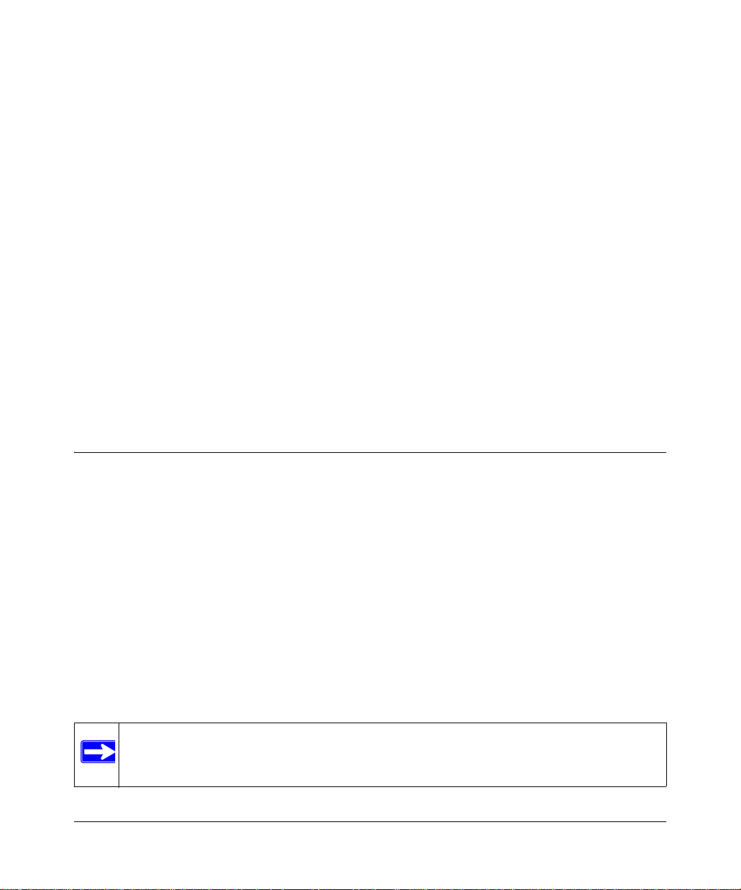
4. Start the Smart Wizard Discovery utility.
5. Click Discover for the Smart Wizard Discovery utility to find your GS108T Gigabit Smart
Switch. You should see a screen similar to the following one.
.
Figure 1-1
Getting Started with Switch Management 1-3
v1.0, December 2007
Page 18
GS108T Smart Switch Software Administration Manual
6. Make a note of the displayed IP address assigned by the DHCP server. You will need this
value to access the switch directly from a Web browser (without using the Smart Wizard
Discovery utility).
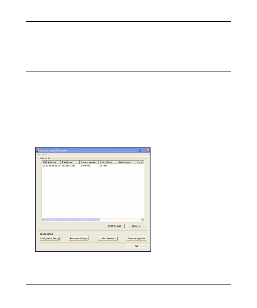
7. Select your switch by clicking the line that shows it. Then click the Web Access button. The
discovery utility displays a login window similar to the following:
.
Figure 1-2
Use your Web browser to manage your switch. The default password is password. Then use this
screen to proceed to management of the switch, as covered in
Chapter 2, “Introduction to the Web
Browser Interface.”
Network without a DHCP Server
This section describes how to set up your switch in a network without a DHCP server, and is
divided into the following tasks:
• Manually assign network settings for your switch.
• Configure the NIC settings on the host PC.
• Log in to the Web-based switch management utility.
1-4 Getting Started with Switch Management
v1.0, December 2007
Page 19
GS108T Smart Switch Software Administration Manual
Manually Assigning Network Settings
If your network has no DHCP service, you must assign a static IP address to your switch. If yo u
choose, you can assign it a static IP address even if your network has DHCP service. Proceed as
follows:
1. Connect the GS108T Gigabit Smart Switch to your existing network.
2. Power on the switch by plugging in the AC-DC power adapter (the default IP is
192.168.0.239).
3. Install the Smart Wizard Discovery utility on your computer.
4. Start the Smart Wizard Discovery utility.
5. Click Discover for the Smart Wizard Discovery utility to find your GS108T Gigabit Smart
Switch. You should see a screen similar to that shown in
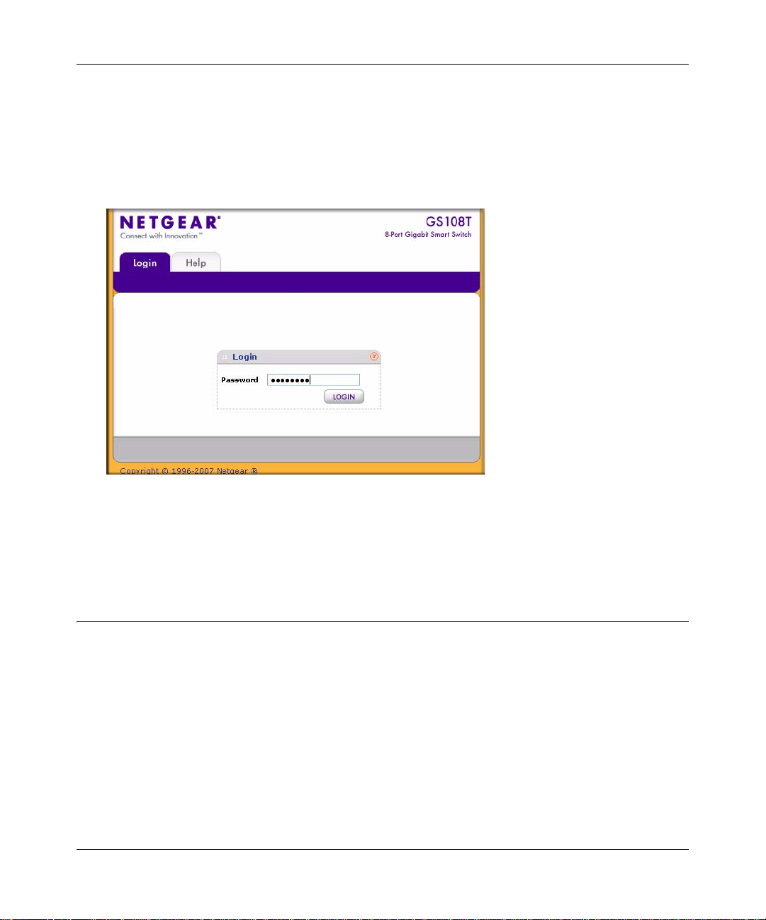
6. Click Configuration Setting. A screen similar to the following one displays.
.
Figure 1-1 on page 1-3.
Figure 1-3
7. Select the Disable radio button to disable DHCP.
8. Enter your chosen switch IP address, gateway IP address, and subnet mask, and then type your
password, and click Set. Ensure that your PC and the GS108T Gigabit Smart Switch are in the
same subnet. Make a note of these settings for later use.
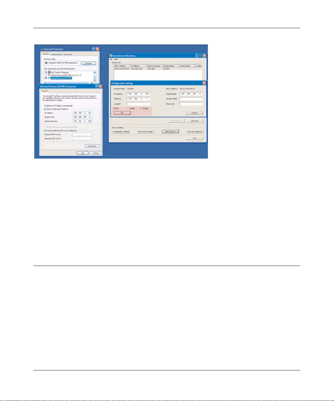
NIC Setting on the Host That Accesses the GS108T Gigabit Smart Switch
You enter the settings of your network interface card (NIC) under the MS Windows OS in
Windows screens similar to the following one. For comparison, the settings screens of the switch
are also shown, although they do not appear in the Windows view.
Getting Started with Switch Management 1-5
v1.0, December 2007
Page 20
GS108T Smart Switch Software Administration Manual
Figure 1-4
You need Windows administrator privileges to change these settings.
1. On your PC, access the MS Windows operating system TCP/IP Properties.
2. Set the IP address and subnet mask appropriately. The subnet mask value should be identical
to that set in the switch. The PC IP address must be different from that of the switch but must
be in the same subnet.
3. Click W eb Access in the Smart Wizard Discovery utility to enable the management screens
described in the following section.
Web Access
For Web access, you do either of the following:
• Using the Smart Wizard Discovery utility, click Web Access (see “Network with a DHCP
Server” or “Network without a DHCP Server”).
• Access the switch directly, without using the Smart Wizard Discovery utility.
You must work from the same network segment that contains the switch (that is, the subnet mask
values of switch and PC host must be the same), and you must point your browser using the switch
IP address. If you used the Smart Wizard Discovery utility to set up IP address and subnet mask,
either with or without DHCP server, use that IP address in your browser window.
1-6 Getting Started with Switch Management
v1.0, December 2007
Page 21
GS108T Smart Switch Software Administration Manual
If you are starting with an “out-of-the-box” switch and are not using the Smart Wizard Discovery
utility, you must initially configure your host PC to be on a network segment to match the default
settings of the switch, which are as follows:
• IP address: 192.168.0.239
• Subnet mask: 255.255.255.0
Later, you might want to change the network settings to match those of your network (this
procedure is described in
“IP Configuration” on page 3-3). Your host PC network settings must
then also be set back to match your network.
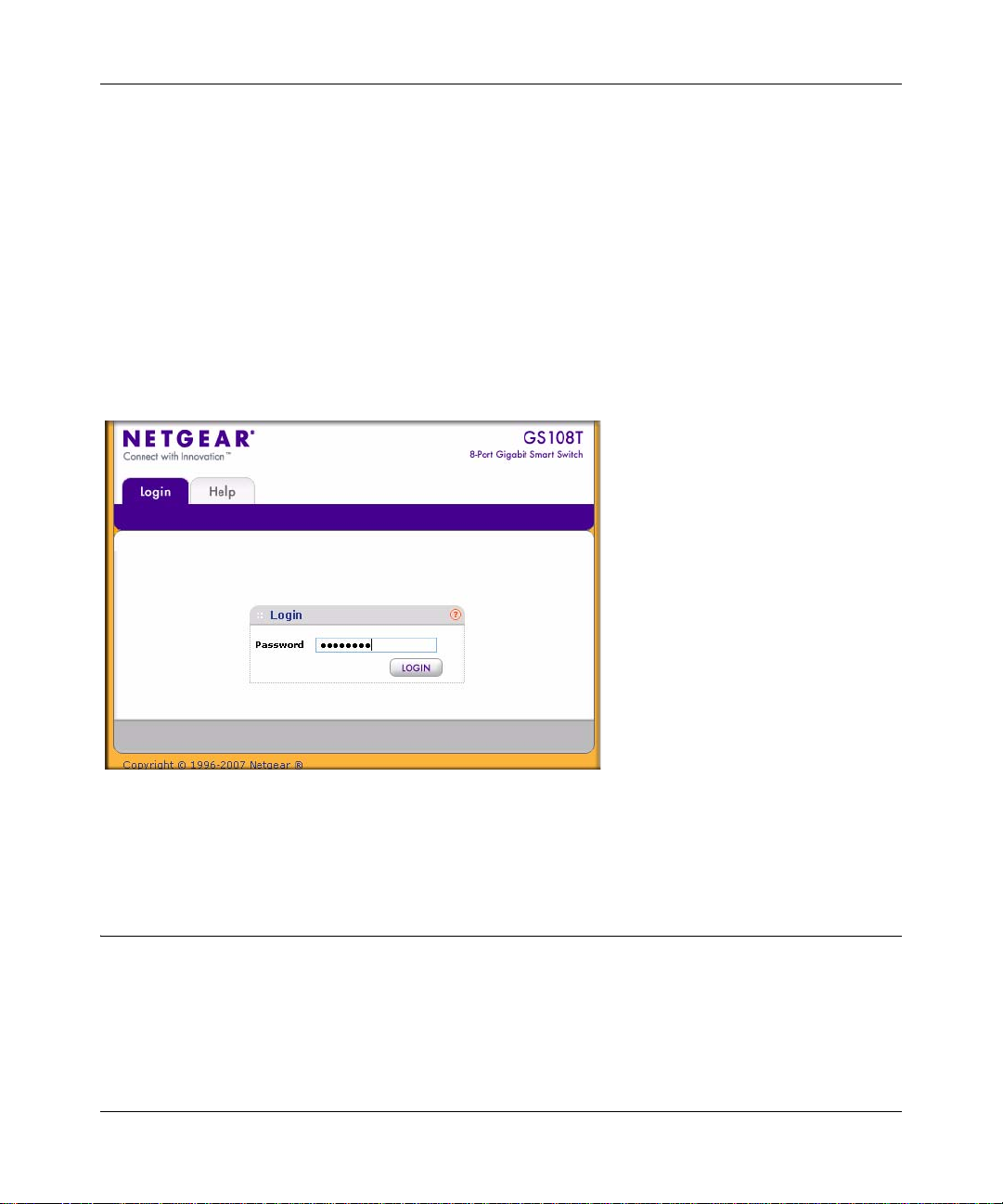
Clicking Web Access on the Smart Wizard Discovery utility or accessing the switch directly
displays the following screen.
.
Figure 1-5
Use this screen to proceed to management of the switch, as covered in Chapter 2, “Introduction to
the Web Browser Interface.”
Additional Utilities
Alternatively, from the main screen shown in Figure 1-1 on page 1-3 you can access additional
functions as described in the following sections:
• “Password Change”
• “Firmware Upgrade”
Getting Started with Switch Management 1-7
v1.0, December 2007
Page 22
GS108T Smart Switch Software Administration Manual
Password Change
You can set a new password of up to 20 ASCII characters.
1. Click Password Change in the Switch Setting section. The Password Change screen displays.
You can set a new password.
2. Enter the old password.
3. Enter the new password, and enter is again to confirm it.
4. Click Set to enable the new password.
Firmware Upgrade
.
Note: You can also upgrade the firmware using the File Download screen of the switch
(see
“File Download” on page 6-20).
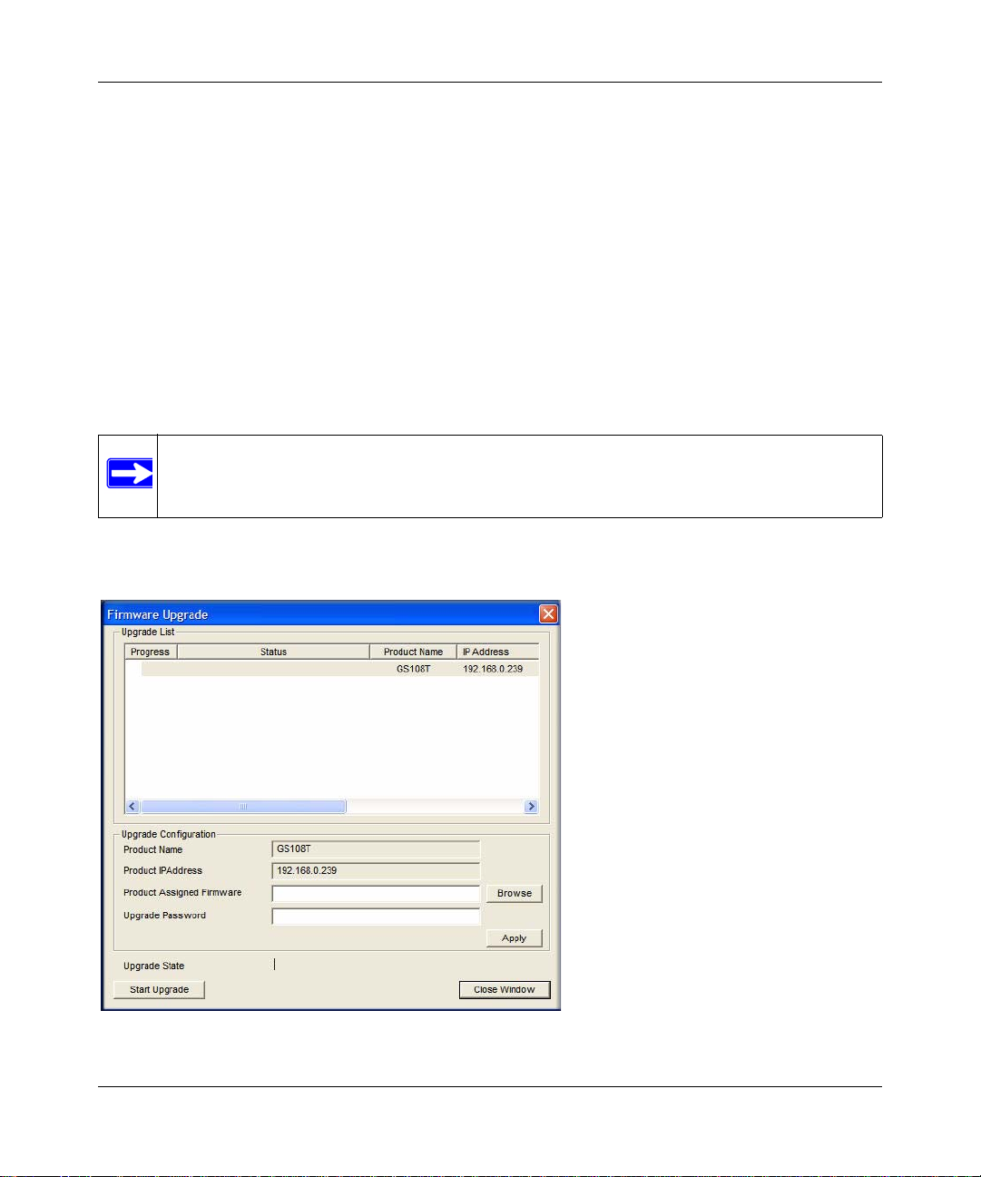
If you click Firmware Upgrade in the main screen (see Figure 1-1 on page 1-3), after you have
selected the switch to upgrade, the following screen displays:
.
Figure 1-6
1-8 Getting Started with Switch Management
v1.0, December 2007
Page 23

GS108T Smart Switch Software Administration Manual
The application software for the GS108T Smart Switch is upgradeable, so you can take advantage
of improvements to your switch and additional features as they become available. The upgrade
procedure and the required equipment are described as follows. This procedure assumes that you
have downloaded or otherwise obtained the firmware upgrade and that you have it available as a
binary file on your computer. For information about downloading firmware, see
“File Download”
on page 6-20.” This procedure uses the TFTP protocol to implement the transfer from computer to
switch.
1. Enter the following values into the appropriate places in the form:
• Firmware Path. The location of the new firmware. If you do not know the location, you
can click Browse to locate the file.
• Password. Enter your password; the default password is password.
• Upgrade State. Shows upgrading in progress.
2. Click Apply.
3. Click Start Upgrade to begin loading the upgrade. The system software is automatically
loaded to all members of a switch stack. When the process is complete, the switch
automatically reboots.
Exit
Click Exit in the Switch Setting section to close the Smart Wizard Discovery utility.
Getting Started with Switch Management 1-9
v1.0, December 2007
Page 24

GS108T Smart Switch Software Administration Manual
1-10 Getting Started with Switch Management
v1.0, December 2007
Page 25
Chapter 2
Introduction to the Web Browser Interface
This section introduces the browser interface that lets you configure and manage your NETGEAR
GS108T Gigabit Smart Switch. Your GS108T Smart Switch provides a built-in browser interface
that lets you configure and manage it remotely using a standard Web browser such as Microsoft
Internet Explorer or Netscape Navigator. Online help is also provided for many of the basic
functions and features of the switch.
Note: When a screen displays, click the help icon for additional information about
the screen settings.
This section introduces the areas of the browser interface and includes the following topics:
• “Logging In to the NETGEAR Home Page”
• “Navigation Tabs”
Logging In to the NETGEAR Home Page
Begin your overview of the GS108T Smart Switch browser interface by logging in:
1. Start the application, either through the Smart W izard Discovery utility or directly by enteri ng
the switch’s IP address, as described in
2. Press Enter. The Login screen displays.
Chapter 1, “Getting Started with Switch Management.”
2-1
v1.0, December 2007
Page 26
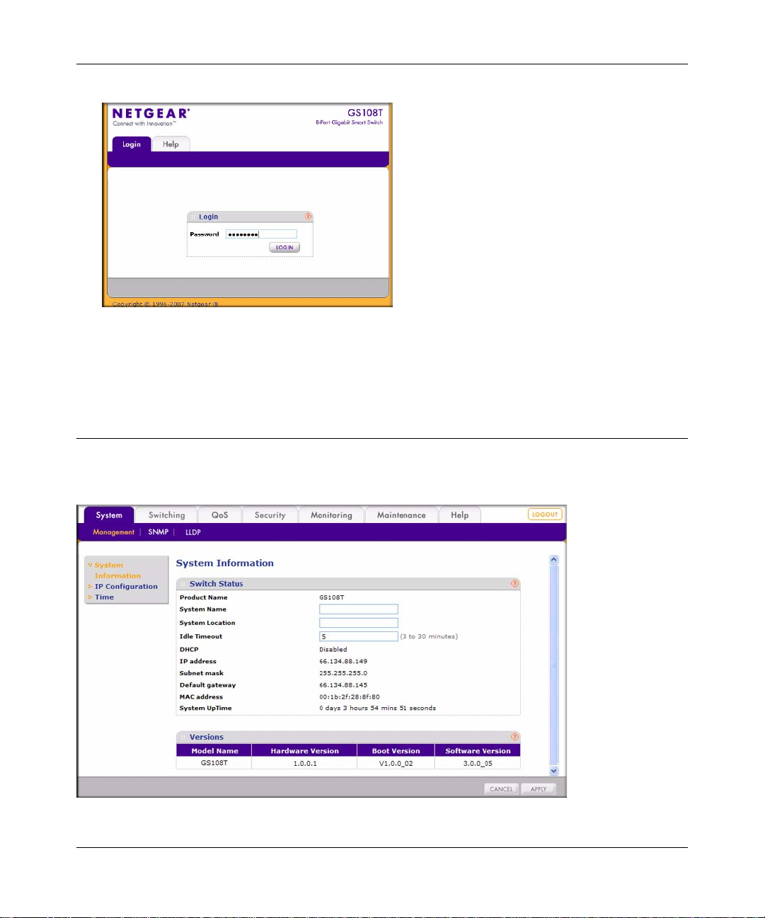
GS108T Smart Switch Software Administration Manual
Figure 2-1
3. Enter the password (the factory default is password), and click Login. The first screen of the
GS108T Smart Switch browser interface is displayed.
Navigation Tabs
Logging in displays the browser interface.
.
Figure 2-2
2-2 Introduction to the Web Browser Interface
v1.0, December 2007
Page 27

GS108T Smart Switch Software Administration Manual
The navigation tabs across the top provide access to all the configuration functions of the switch,
and remain constant. The menu items in the blue bar change according to the navigation tab that is
selected.
For further description of the functions, see the appropriate section of this manual:
• Chapter 3, “Managing System Settings,” describes how to configure the system functions.
• Chapter 4, “Configuring Switching,” describes how to configure the switching functions.
• Chapter 5, “Configuring QoS and Security,” describes how to configure the QoS and security
functions.
• Chapter 6, “Monitoring, Maintenance, and Help,” describes how to display statistics, how to
reset the switch, how to upload and download files such as firmware, and how to obtain further
help.
Click the Logout button to log out of the browser interface.
Introduction to the Web Browser Interface 2-3
v1.0, December 2007
Page 28

GS108T Smart Switch Software Administration Manual
2-4 Introduction to the Web Browser Interface
v1.0, December 2007
Page 29

Chapter 3
Managing System Settings
Using the System Tab
The navigation tabs on the top of the home page include a System tab that lets you manage your
GS108T Gigabit Smart Switch using features under the following main menu commands and
subcommnands:
• “Management”
• “System Information”
• “IP Configuration”
• “Time”
• “SNMP”
• “SNMP V1/V2”
• “LLDP”
• “Basic—LLDP Configuration”
• “Advanced—LLDP Configuration”
• “Advanced—LLDP Port Settings”
• “Advanced—Local Information”
• “Advanced—Neighbors Information”
The sections that follow in this chapter cover these features and tell you how to set them in the
GS108T Smart Switch.
Management
This section describes how to display the switch status and specify some basic switch information,
how to configure the system IP address source, and how to configure the system clock source.
3-1
v1.0, December 2007
Page 30
GS108T Smart Switch Software Administration Manual
System Information
The System Information screen displays the system settings and lets you to change some of the
configurable settings of the switch:
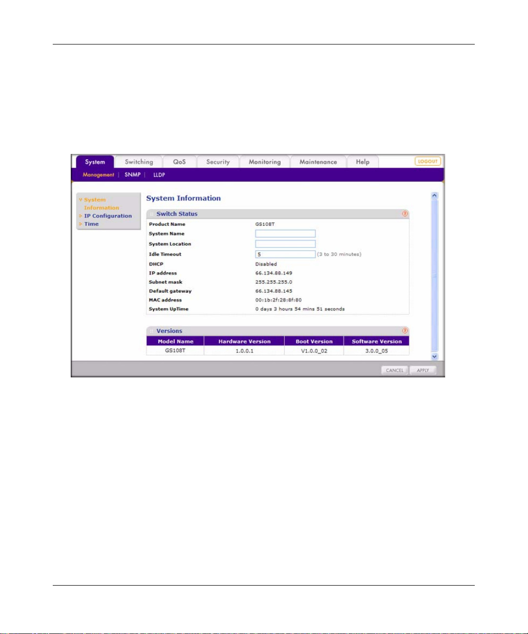
1. Select System > Management > System Information. A screen similar to the following
displays.
.
Figure 3-1
2. View the basic system information under Switch Status. You can also change some of the
configurable fields of the switch:
• Product Name. Shows the switch model name.
• System Name. This is a configurable field. You can assign a system na me for the switch.
This name lets you track your switch.
• System Location. This is a configurable field. You can assign a location name for the
switch. This field assists you in keeping track of which switch you are connected to when
you are connected to your switch remotely.
• Idle Timeout. This is a configurable field. You can assign a duration for login time-out.
Users are automatically logged out when the login session remains idle after the specified
duration. This allows other users to access the switch if one forgets to log out.
• DHCP. Shows the enabled or disabled state of DHCP client functionality.
3-2 Managing System Settings
v1.0, December 2007
Page 31

GS108T Smart Switch Software Administration Manual
• IP Address. Shows the IP address of the switch.
• Subnet mask. Shows the subnet mask of the IP address.
• Default gateway . Shows the IP address of the gateway for the remote manager.
• MAC address. Shows the MAC address of the switch.
• System UpTime. Shows the switch up time after bootup.
3. Click Apply if you have made any change to the System Name, System Location, or Idle
Timeout setting.
4. View the system hardware and software version information under the Versions heading:
• Model Name. Shows the switch model name.
• Hardware Version. Shows the switch hardware version.
• Boot Version. Shows the boot code versio n of the switch.
• Software Version. Shows the software version of the switch.
IP Configuration
The IP Configuration screen lets you set the system IP address source and optional management
VLAN:
1. Select System > Management > IP Configuration. A screen similar to the following displays.
Figure 3-2
Managing System Settings 3-3
v1.0, December 2007
Page 32

GS108T Smart Switch Software Administration Manual
2. Select the appropriate radio button for your IP configuration:
• Get Dynamic IP from DHCP Server. Specifies that the switch must obtain the IP address
through a DHCP server.
• Get Dynamic IP from BootP Server. Specifies that the switch must obtain the IP address
through a BootP server.
• Static IP Address. Specifies that the IP address, subnet mask, and default gateway must
be manually configured. Enter this information in the fields below this radio button.
3. Select the management VLAN ID (the default is 0 for all VLANs).
The management VLAN is used to establish an IP connection to the switch from a workstation
that is connected to a port in the VLAN. If not specified, the active management VLAN ID is
0 (default), which allows an IP connection to be established through any port.
When the management VLAN is configured, an IP connection can be made only through a
port that is part of the management VLAN. It is also mandatory that the port VLAN ID (PVID)
of the port to be connected in that management VLAN be the same as the management
VLAN
ID.
• Only one management VLAN can be active at a time.
• When a new management VLAN is configured, connectivity through the existing
management VLAN is lost.
• The management station should be reconnected to the po rt in the new management
VLAN.
Note: Make sure that the VLAN to be configured as the management VLAN exists.
And make sure that the PVID of at least one port that is a port of the VLAN is
the same as the management VLAN ID.
4. Click Apply to confirm any settings changes.
Time
Simple Network Time Protocol (SNTP) synchronizes time across the network.
• The time interval at which the switch polls for time is called the polling time and is set to
30
minutes. As long as the NTP/SNTP server is reachable, the switch polls for time every
minutes and updates the system time.
30
3-4 Managing System Settings
v1.0, December 2007
Page 33

GS108T Smart Switch Software Administration Manual
• The time-out period is the time duration for which the switch waits for a reply from the server.
Time-out is set to 15 seconds. If two NTP/SNTP servers are specified and neither one is
available, then the total time-out is 30 seconds.
You can specify whether to set the system time manually or with an SNTP server:
1. Select System > Management > Time. A screen similar to the following displays.
.
Figure 3-3
2. Select a Clock Source:
• Local. Date and time are calculated through a local clock source that is based on CPU
cycles. Go to
step 3.
• SNTP. Date and time are selected through an SNTP server. Go to step 5
3. When setting the date and time through a local clock source, enter the following:
a. Date. Specify the date to which the switch is set in the DD/MM/YYYY format.
b. Local Time. Specify the switch time in the HH:MM:SS format.
4. Time Zone. Select the local time zone in which the switch is operating.
5. When setting the date and time through an SNTP server, enter the following settings:
a. In the NTP Server IP - 1 field, specify the IP address of the primary NTP/SNTP server
for the switch to use when synchronizing time.
b. In the NTP Server IP - 2 field, specify the IP address of alternate NTP/SNTP server for
the switch to use when synchronizing time.
6. Click Apply to confirm any settings changes.
Managing System Settings 3-5
v1.0, December 2007
Page 34

GS108T Smart Switch Software Administration Manual
SNMP
The SNMP screen lets you specify a Simple Network Management Protocol (SNMP) management
station and related SNMP settings, and set an authentication fail trap.
SNMP V1/V2
The SNMP V1/V2 screen lets you limit the IP addresses that can access the management
information base (MIB) of the switch and to which the switch sends the traps. The switch responds
only to requests from management stations that have their IP address in the management station
list. You can also select the traps that the switch sends to the management station after a trap event.
The setting of a management station is not active until you set the Status field to Enable. To
configure management stations:
1. Select System > SNMP > SNMP V1/V2. A screen similar to the following displays.
.
Figure 3-4
2. Under Community Configuration & Trap Flags, view or specify the SNMP settings for up to
four management stations:
• Management Station. Sets the community's management station IP address.
• Community String. Sets the community string. The community string provides an
authentication mechanism to the SNMP protocol. The switch processes requests from the
management station only if the community string in the request packet matches the
community string that is specified in the Community String field.
• Access Mode. Sets the access privilege (Read Only or Read Write) state of the
management station.
• Trap (T2). Enables the switch to generate an SNMP trap when it reboots.
3-6 Managing System Settings
v1.0, December 2007
Page 35

GS108T Smart Switch Software Administration Manual
• Trap (T3). Enables the switch to generate an SNMP trap when one of its ports changes its
link status.
• Status. Enables or disa bles the management station.
3. If you have added a management station, click Add. If you have selected one or more
management stations for removal, click Remove. If you have made any changes to an existing
management station, click Apply.
4. Under Authentication Fail Trap, select the Enable Authentication Fail Trap check box to
enable the switch to generate an SNMP trap for all management stations when a computer
attempts to gain access to the switch through SNMP but the computer’s IP address is not in the
SNMP management station table.
5. If you have made changes to the Enable Authentication Fail Trap check box, click Apply.
LLDP
Link Layer Discovery Protocol (LLDP) is a one-way protocol that provides the following
capabilities:
• An LLDP agent can transmit information about the capabilities and current status of the switch
associated with its MAC Service Access Point (MSAP) identifier.
• An LLDP agent can also receive information about the capabilities and current status of the
switch associated with a remote MSAP identifier.
LLDP agents do not solicit information from other LLDP agents using LLDP.
Basic—LLDP Configuration
The Basic LLDP Configuration screen lets you to enable or disable LLDP and configure the basic
LLDP settings:
1. Select System > LLDP > Basic > LLDP Configuration. A screen similar to the following
displays.
Managing System Settings 3-7
v1.0, December 2007
Page 36

GS108T Smart Switch Software Administration Manual
.
Figure 3-5
2. Select a radio button to enable or disable LLDP:
• Disable. LLDP is disabled (default).
• Enable. LLDP is enabled.
3. When LLDP is disabled, select how LLDP packets are processed from the LLDPDU
Handling drop-down list:
• Flooding. LLDPDU packet flooding is enabled. LLDP packets that are received from
another LLDP device are flooded, that is, the packets are forwarded to all devices that are
attached to the switch.
• Filtering. LLDPDU packet filtering is enabled. LLDP packets that are received from
another LLDP device are dropped.
4. When LLDP is enabled, the following configurable LLDP settings are displayed:
• TLV Advertised Interval (5–32768 sec). The interval at which LLDP frames are
transmitted on behalf of this LLDP agent. The default is value is 30 seconds.
• Hold Multiplier (2–10). A multiplier to the advertised interval. The result is the time-to-
live (TTL) value for the information that is advertised. The default value is 4.
• Reinitializing Delay (1–10 sec). The minimum delay period from the time a port becomes
disabled until its reinitialization. The default value is 2 seconds.
• Transmit Delay (1–8192 sec). The delay between successive LLDP frame transmissions
that are initiated by a value or status changes in the local system. The default value is 2
seconds.
3-8 Managing System Settings
v1.0, December 2007
Page 37

GS108T Smart Switch Software Administration Manual
• Notification Interval (5–3600 sec). The interval at which notifications are generated
when remote MSAP information changes. The default value is 5 seconds.
• Fast Start Count (2–10). The number of successive LLDP frame transmissions for one
complete fast-start interval. The default value is 4.
5. Click Apply to confirm any settings changes.
Advanced—LLDP Configuration
The Advanced LLDP Configuration screen is identical to the Basic LLDP Configuration screen.
See the previous section.
Advanced—LLDP Port Settings
When LDDP is enabled, you can view the LLDP port settings in the LDDP Port Settings screen:
1. Select System > LLDP > Advanced > LLDP Port Settings. A screen similar to the following
displays.
.
Figure 3-6
2. You can make changes to the LLDP settings for an individual port, for a group of ports, or for
all ports simultaneously:
• To change the LLDP settings for an individual port, select the check box to the left of its
port number, and then select the LLDP port settings.
Managing System Settings 3-9
v1.0, December 2007
Page 38

GS108T Smart Switch Software Administration Manual
• T o change the LLDP settings for a group of ports, select the check boxes to the left of their
port numbers, and then select the LLDP port settings.
• T o change the LLDP settings for all ports simultaneously, select the check box at the top of
the column of check boxes, and then select the LLDP port settings.
The following information about the LLDP configuration for a port is displayed:
• Ports. Shows the port number.
• Admin Status. The administratively assigned status of the local LLDP agent. The possible
field values are:
– TX Only. Specifies that transmission of local LLDP information only is enabled.
– RX Only. Specifies that reception of remote LLDP information only is enabled.
– TX and RX. Specifies that both transmission and reception of LLDP information are
enabled.
– Disable. Specifies that both transmission and reception of LLDP information are
disabled.
• Notification. Specifies whether or not transmission notifications are enabled.
• MED Notification. Specifies whether or not Media Endpoint Discovery (MED)
transmission notifications are enabled.
• Optional TLVs. Specifies whether or not the transmission of threshold limit values
(TLVs) is enabled.
3. Click Apply to confirm any settings changes.
3-10 Managing System Settings
v1.0, December 2007
Page 39

GS108T Smart Switch Software Administration Manual
Advanced—Local Information
When LDDP is enabled, you can view the LLDP local information in the Local Information
screen, which is also referred to as the LLDP Local Device Information screen:
Select System > LLDP > Advanced > LLDP Port Settings. A screen similar to the following
displays.
Figure 3-7
Managing System Settings 3-11
v1.0, December 2007
Page 40

GS108T Smart Switch Software Administration Manual
Under Device Information, the following LLDP local information is displayed:
Note: When LLDP is disabled, all local information fields display N/A.
• Chassis ID SubType. Shows the basis for the chassis ID entity.
• Chassis ID. Shows the identifier for the particular chassis in the system.
• System Name. Shows the administratively assigned system name.
• System Description. Shows a textual description of the network entity, including the full
name and version identification of the system’s hardware type.
• System Capabilities. Shows the primary functions of the system.
• Enabled Capabilities. Shows which of the primary functions are enabled.
• MED Device Type. Shows whether the device is a MED device.
• Management Address. Shows the address that is associated with the LLDP agent that can be
used to reach higher-layer entities to assist discovery by network management.
Table 3-1. Management Address
Item Description
Address
Sub-type
Address Shows the management IP address.
Interface
Sub-type
Interface
Number
OID Shows the type of hardware component or protocol entity that is associated with
Shows the type of address that is listed in the management address field.
Shows the numbering method used for defining the interface number.
Shows the specific address associated with the management address.
the management address.
Under Port Information, the following LLDP port information is displayed:
• Port. Shows the local port number.
• Port ID SubType. Shows the basis for the identifier that is listed in the Port ID field.
• Port ID. Shows the identifier for the port from which the LLDPDU was transmitted.
• Port Description. Shows the port’s description.
3-12 Managing System Settings
v1.0, December 2007
Page 41

GS108T Smart Switch Software Administration Manual
Under Port Information, click a port number in the Port column. A screen similar to the following
displays.
Figure 3-8
The following LLDP local port information is displayed:
Table 3-2. MSAP Details
Item Description
Port ID SubType The basis for the identifier that is listed in the Port ID field.
Port ID Identifier for the port from which LLDPDU was transmitted.
Table 3-3. 802.1 Set Details
Item Description
PVID The Port VLAN ID.
Managing System Settings 3-13
v1.0, December 2007
Page 42

GS108T Smart Switch Software Administration Manual
Table 3-4. 802.3 Set Details
Item Description
Auto-Negotiation If autonegotiation supported and enabled in both the systems, there should be no
speed difference.
Aggregator Status Whether the port through which LLDPDU is transmitted is aggregated or not.
Aggregator Id Port ID information for the aggregated port.
Maximum Frame
Size
Maximum size of a frame that can be transmitted.
Table 3-5. MED Set Details
Item Description
Capabilities LLDP-MED capabilities are specific to LLDP-MED devices. Advertisement of this TLV by
endpoints enables LLDP-MED-capable network connectivity devices to determine
support of LLDP-MED by endpoints that they are connecting to.
Device Type A specific type of LLDP-MED device, which can be either a network connectivity device
or a specific class of endpoint device.
Location
Format
Location ID Three Location ID data formats are defined:
Power Type Shows whether LLDP-MED device transmitting the LLDPDU is a Power Sourcing Entity
Power
Source
Power
Priority
Shows the specific Location ID data format being delivered in the Location ID field.
• Coordinate-based LCI data format
• Civic Address LCI data format
• ECS ELIN data format
(PSE) or Power Device (PD).
The power source being utilized by a PSE or PD device.
The priority of the PD type device to the power being supplied by the PSE type device, or
the power priority associated with the PSE type device's port that is sourcing the power
through MDI.
3-14 Managing System Settings
v1.0, December 2007
Page 43

GS108T Smart Switch Software Administration Manual
Table 3-5. MED Set Details (continued)
Item Description
Power Value Shows the total power in watts required by a PD device from a PSE device, or the total
power a PSE device is capable of sourcing over a maximum-length cable based on its
current configuration.
Network
Policies
Network policy is associated with multiple sets of application types supported on a given
port.
• Application Type. Integer value indicating the primary function of the applications
defined for this network policy, advertised by an endpoint or network connectivity
device.
• Unknown Policy. Shows that an endpoint device wants to explicitly advertise that this
policy is required by the device but is currently unknown.
• Tagged. Shows whether the specified application type is using a tagged or an
untagged VLAN.
• VLAN ID. Contains the VLAN identifier (VID) for the port.
• L2 Priority. Shows the Layer 2 priority to be used for the specified application type.
• DSCP. Contains the DSCP value to be used to provide Diffserv node behavior for the
specified application type.
Advanced—Neighbors Information
When there are local LLDP neighbors, you can view the remote information in the Neighbors
Information screen:
Select System > LLDP > Advanced > Neighbors Information. A screen similar to the following
displays.
.
Figure 3-9
Under Neighbors Information, the following information is displayed:
• MSAP Entry. Shows the MSAP identifier from which the LLDPPU was transmitted.
• Local Port. Shows the local port on which the LLDPDU was received.
Managing System Settings 3-15
v1.0, December 2007
Page 44

GS108T Smart Switch Software Administration Manual
• Chassis ID SubType. Shows the basis for the chassis ID that is listed in the Chassis ID field.
• Chassis ID. Shows the chassis ID of the system from which the LLDPPU was transmitted.
• Port ID SubType. Shows the basis for the identifier that is listed in the Port ID field.
• Port ID. Shows the port from which the LLDPDU was transmitted.
3-16 Managing System Settings
v1.0, December 2007
Page 45

Chapter 4
Configuring Switching
Using the Switching Tab
The navigation tabs on the top of the home page include a Switching tab that lets you manage your
GS108T Gigabit Smart Switch using features under the following main menu commands and
subcommnands:
• “Ports”
• “Port Configuration”
• “LAG”
• “Basic—LAG Configuration”
• “Basic—LAG Membership”
• “Advanced—LAG Configuration”
• “Advanced—LAG Membership”
• “Advanced—LACP Configuration”
• “Advanced—LACP Port Configuration”
• “VLAN”
• “Basic—VLAN Configuration”
• “Advanced—VLAN Configuration”
• “Advanced—VLAN Membership”
• “Advanced—Port PVID Configuration”
• “STP”
• “Basic—RSTP Configuration”
• “Advanced—RSTP Configuration”
• “Advanced—Port Configuration”
• “Multicast”
• “IGMP Snooping”
• “Static Multicasting”
• “Multicast Group Membership”
v1.0, December 2007
4-1
Page 46

GS108T Smart Switch Software Administration Manual
• “Switch Configuration”
• “Jumbo Frame Configuration”
• “Address Table”
• “Static Address”
• “Dynamic Address”
The sections that follow in this chapter cover these features and tell you how to configure them in
the GS108T Smart Switch.
Ports
You can define speed, duplexing, and flow control operation for a port when autonegotiation is off.
When autonegotiation is on, those data are negotiated from the link partner. Otherwise, you can
enable or disable ports to control packet forwarding.
Port Configuration
The Port Configuration screen lets you to define the port switching settings:
1. Select Switching > Ports > Port Configuration. A screen similar to the following displays.
.
Figure 4-1
4-2 Configuring Switching
v1.0, December 2007
Page 47

GS108T Smart Switch Software Administration Manual
2. You can make changes to the port switching settings for an individual port, for a group of
ports, or for all ports simultaneously:
• T o change the port switching settings for an individual port, select the check box to the left
of its port number, and then select the port switching settings.
Note: You can also enter the interface number (that is, the port number) in the GO
TO INTERFACE field, and then click GO.
• T o change the port switching settings for a group of ports, select the check boxes to the left
of their port numbers, and then select the port switching settings.
• To change the port switching settings for all ports simultaneously, select the check box at
the top of the column of check boxes, and then select the port switching settings.
The following port switching settings are displayed for all ports. Except for the Interface and
Link Status fields, all fields are configurable.
• Interface. Shows the port number.
• Port Description. Specifies the optional port description.
• Link Status. Shows whether the link is up or down.
• Port Speed. Specifies the speed for the port. The possible fields values are:
– 100M. Specifies that the port speed is 100 Mbps.
– 10M. Specifies that the port speed is 10 Mbps.
– Auto. Specifies that autonegotiation mode is enabled. Select this mode when you
want the port speed to function at 1000
Mbps.
– Disable. Specifies that the port speed is disabled.
• Duplex Mode. Specifies the duplex mode. The possible fields values are:
– Full. Specifies that full-duplex mode is enabled.
– Half. Specifies that half-duplex mode is enabled. This mode can be enabled only
when the port speed is 10 Mbps or 100 Mbps.
• Flow Control. Specifies whether flow control support is enabled or disabled:
– Enable. Specifies that flow control is enabled. If the port is oversubscribed, it sends a
pause frame or a jam packet. If the port receives a pause frame, it halts for a certain
period before sending out a frame.
– Disable. Specifies that flow control is disabled.
Configuring Switching 4-3
v1.0, December 2007
Page 48

GS108T Smart Switch Software Administration Manual
• Default Priority . Specifies the packet priority for packets arriving at the port without
tagging. The possible fields values are: 0–7. If packet arrives with a tag or priority tag, the
priority is retrieved from the priority field of the tag.
3. Click Apply to confirm any settings changes.
LAG
Two types of link aggregation groups (LAGs) are supported:
• Static Trunking. Ports are grouped manually.
• Link Aggregation Control Protocol (LACP). Part of IEEE specification (802.3ad) that
allows several physical ports to be bundled together to form a single logical channel. Link
aggregation allows one or more links to be aggregated together to form a LAG, such that a
MAC client can treat the LAG as if it were a single link. Link aggregation can be used on
10-Mbps, 100-Mbps, or 1000-Mbps Ethernet full-duplex ports.
Example: A network administrator could combine a group of five 100-Mbps ports into a logical
link that will function as a single 500-Mbps port (the actual throughput, however , will be less than
the total sum of the links).
Basic—LAG Configuration
The Basic LAG Configuration screen lets you define the status and administration settings for up
to two available LAGs. However, you first have to define the members of the LAGs. See
LAG Membership” on page 4-5. To configure LAG:
1. Select Switching > LAG > Basic > LAG Configuration. A screen similar to the following
displays.
Figure 4-2
4-4 Configuring Switching
v1.0, December 2007
“Basic—
Page 49

GS108T Smart Switch Software Administration Manual
2. You can make changes to the LAG settings for an individual LAG or for both LAGs
simultaneously:
• To change the LAG settings for an individual LAG, select the check box to the left of its
LAG ID, and then select the LAG settings.
• T o change the LAG settings for both LAGs simultaneousl y, select the check box at the top
of the column of check boxes, and then select the LAG settings.
The following LAG settings are displayed for both LAGs. Except for the LAG ID and LAG
State fields, all fields are configurable.
• LAG ID. Shows the LAG ID.
• Admin Mode. Specifies the LAG administrative mode. The possible fields values are:
– Enable. The LAG administrative mode is enabled.
– Disable. The LAG administrative mode is disabled.
• LAG Description: Specifies the optional LAG description.
• LAG State. Shows whether the LAG is enabled or disabled.
• LACP. Specifies whether LACP enabled or disabled for the LAG. The possible fields
values are:
– Up. LACP is enabled. (If the administrative mode is disabled, LACP cannot be up.)
This implies that static trunking is disabled.
– Down. LACP is disabled. This implies that static trunking is enabled.
3. Click Apply to confirm any settings changes.
Note: In order for you to successfully apply a LAG configuration, all members of the
trunk must be selected before you enable the LAG configuration, must have the
same speed and duplex modem, and must be either linked or unlinked.
Basic—LAG Membership
The Basic LAG Membership screen lets you define the ports that are aggregated together to form a
single LAG. There are certain requirements for a LAG:
• Each port can belong to only one LAG.
• Each LAG can have up to four ports.
• Ports in a LAG must have the same speed and be in the same VLAN group.
To configure LAG membership:
1. Select Switching > LAG > Basic > LAG Membership. A screen similar to the following
displays.
Configuring Switching 4-5
v1.0, December 2007
Page 50

GS108T Smart Switch Software Administration Manual
.
Figure 4-3
2. From the LAG ID drop-down list, select 1 or 2.
3. Click Unit 1. A screen similar to the following displays.
Figure 4-4
4. Select up to four ports for membership in the LAG by selecting the check boxes below the port
numbers.
5. Click Apply to confirm any settings changes.
Advanced—LAG Configuration
The Advanced LAG Configuration screen is identical to the Basic LAG Configuration screen. See
“Basic—LAG Configuration” on page 4-4.
Advanced—LAG Membership
The Advanced LAG Membership screen is identical to the Basic LAG Membership screen. See
“Basic—LAG Membership” on page 4-5.
4-6 Configuring Switching
v1.0, December 2007
Page 51

GS108T Smart Switch Software Administration Manual
Advanced—LACP Configuration
The LACP Configuration screen lets you set the LACP system priority, which specifies the
device’s link aggregation priority relative to the de vices at the other ends of the links on which link
aggregation is enabled. To configure LACP:
1. Select Switching > LAG > Advanced > LACP Configuration. A screen similar to the
following displays.
Figure 4-5
The LACP System Setting field is the only configurable field in this screen:
• LACP System Setting. LACP Port priority ranges from 0 to 65536. A higher value
indicates a lower priority. The default value is randomly selected.
2. Click Apply to confirm any settings changes.
Advanced—LACP Port Configuration
The LACP Port Configuration screen, which is also referred to as the LACP Port Priority screen,
lets you set the LACP port priority and time-out value:
1. Select Switching > LAG > Advanced > LACP Port Configuration. A screen similar to the
following displays.
Configuring Switching 4-7
v1.0, December 2007
Page 52

GS108T Smart Switch Software Administration Manual
Figure 4-6
2. You can make changes to the LACP port priority settings for an individual port, for a group of
ports, or for all ports simultaneously:
• To change the LACP port priority settings for an individual port, select the check box to
the left of its port number, and then select the LACP port priority settings.
Note: You can also enter the interface number (that is, the port number) in the GO
TO INTERFACE field, and then click GO.
• To change the LACP port priority settings for a group of ports, select the check boxes to
the left of their port numbers, and then select the LACP port priority settings.
• To change the LACP port priority settings for all ports simultaneously, select the check
box at the top of the column of check boxes, and then select the LACP port priority
settings.
The following information about the LACP priority for a port is displayed. Both the LACP
Priority and Timeout fields are configurable.
• Port. Shows the port number.
• LACP Priority. Specifies the port priority value in a range from 1 to 65335.
4-8 Configuring Switching
v1.0, December 2007
Page 53

GS108T Smart Switch Software Administration Manual
• Timeout. Specifies the administrative LACP time-out. The possible field values are:
– Long. Specifies a long time-out value.
– Short. Specifies a short time-out value.
3. Click Apply to confirm any settings changes.
VLAN
A virtual local area network (VLAN) is a way to electronically separate ports on the same switch
(from a single broadcast domain) into separate broadcast domains so that broadcast packets are not
sent to all the ports on a single switch. When you use a VLAN, users can be grouped by logical
function instead of physical location. The GS108T Smart Switch supports IEEE
and port-based VLANs, but not combination of both:
• IEEE 802.1Q VLANs
The settings on the IEEE 802.1Q VLAN screen control the VLAN membership of each port
for transmitting packets. Also, these settings determine if transmitted packets from each port
are tagged with the VLAN ID and other information. The switch supports 64 tag-based
VLANs.
802.1Q VLANs
By default, every port is a member of VLAN 1, and so they have a port VLAN ID (PVID)
of
1.
• Port-based VLANs
Single or multiple ports are grouped into a smaller virtual network, which is independent of
the other ports. The switch supports 8 port-based VLANs. Any user-assigned VLAN cannot
have member ports that belong to different port groups.
Basic—VLAN Configuration
The Basic VLAN Configuration screen lets you select the VLAN type and create VLANs. Y ou can
select to create either IEEE
differently for IEEE 802.1Q VLANs than it does for port-based VLANs.
IEEE 802.1Q VLAN Configuration
To configure the IEEE 802.1Q VLAN type:
1. Select Switching > VLAN > Basic > VLAN Configuration. A screen similar to the following
displays.
Configuring Switching 4-9
802.1Q VLANs or port-based VLANs. The screen functions
v1.0, December 2007
Page 54

GS108T Smart Switch Software Administration Manual
.
Figure 4-7
2. Select the IEEE 802.1Q radio button to specify the IEEE 802.1Q VLAN type.
Warning: Changing the VLAN type erases all existing VLAN settings, static
multicast groups, and trusted MAC addresses.
3. The Warning screen displays. Click OK.
The following information about the VLAN configuration is displayed. Both the VLAN ID
and VLAN Name fields are configurable:
• VLAN ID. Specifies a VLAN ID from 1 to 4094.
• VLAN Name. Specifies the optional VLAN description.
4. Perform one of the following actions:
To add a VLAN:
a. Enter a number in the VLAN ID field.
b. Enter a name in the VLAN Name field.
c. Click Add.
To delete a VLAN:
a. Select the check box to the left of the VLAN ID that you want to remove.
b. Click Delete.
4-10 Configuring Switching
v1.0, December 2007
Page 55

GS108T Smart Switch Software Administration Manual
To change a VLAN name:
a. Select the check box to the left of the VLAN ID that you want to change.
b. Enter a new name in the VLAN Name field.
c. Click Apply.
Port-Based VLAN Configuration
To configure the port-based VLAN type:
1. Select Switching > VLAN > Basic > VLAN Configuration. A screen similar to the following
displays.
Figure 4-8
2. Select the Port-Based radio button to specify the port-based VLAN type.
Warning: Changing the VLAN type erases all existing VLAN settings, static
multicast groups, and trusted MAC addresses.
3. The Warning screen displays. Click OK.
4. In the VLAN Name field, enter an optional VLAN name.
Configuring Switching 4-11
v1.0, December 2007
Page 56

GS108T Smart Switch Software Administration Manual
5. Perform one of the following actions:
• To add a VLAN:
– Select the check box to the left of one of the VLAN IDs.
– Enter a VLAN name in the VLAN Name field.
– Click Add.
• To delete a VLAN:
– Select the check box to the left of the VLAN ID that you want to remove.
– Click Delete.
• To change a VLAN name:
– Select the check box to the left of the VLAN ID that you want to change.
– Enter a new name in the VLAN Name field.
– Click Apply.
Advanced—VLAN Configuration
The Advanced VLAN Configuration screen is identical to the Basic VLAN Configuration screen.
See the previous section.
Advanced—VLAN Membership
The VLAN Membership screen lets you set the VLAN membership of each port. The screen
functions differently for port-based VLANs than it does for IEEE 802.1Q VLANs.
IEEE 802.1Q VLAN Membership
Note: By default, every port is a member of VLAN 1, which has a port VLAN ID
(PVID)
To configure VLAN membership for IEEE 802.1Q VLANs:
1. Select Switching > VLAN > Basic > VLAN Membership. A screen similar to the following
displays.
4-12 Configuring Switching
of 1.
v1.0, December 2007
Page 57

GS108T Smart Switch Software Administration Manual
Figure 4-9
2. From the VLAN Identifier drop-down list, select the number that represents the VLAN you
want to view or modify.
You can either assign the same tag setting to or remove it from all ports in the VLAN in step 3,
or assign a tag setting to or remove it from each individual port in the VLAN in step 4. These
steps are mutually exclusive.
3. T o assign the same tag setting to or remove it from all ports in the VLAN, toggle the check box
to the left of Unit
1. The tag setting determines if packets that are transmitted from each port
are tagged with the VLAN ID and other information. The possible tag settings are:
– T. Specifies that the egress (outgoing) packet is tagged for all ports.
– U. Specifies that the egress packet is untagged for all ports.
– Empty. Specifies that none of the ports are part of the VLAN.
4. To assign a tag setting to or remove it from an individual port in the VLAN:
a. Click Unit 1. A screen similar to the following displays.
Figure 4-10
Configuring Switching 4-13
v1.0, December 2007
Page 58

GS108T Smart Switch Software Administration Manual
b. Assign a tag setting to or remove it from a port by toggling the check box under an
individual port number. The tag settings determine if packets that are transmitted from the
port are tagged with the VLAN ID and other information. The possible tag settings are:
– T. Specifies that the egress packet is tagged for the port.
– U. Specifies that the egress packet is untagged for the port.
– Empty. Specifies that the port is not part of the VLAN.
5. Click Apply to confirm any settings changes.
Port-Based VLAN Membership
To configure VLAN membership for port-based VLANs:
1. Select Switching > VLAN > Advanced > VLAN Membership. A screen similar to the
following displays.
.
Figure 4-11
2. From the VLAN Identifier drop-down list, select the number that represents the VLAN you
want to view or modify.
You can either assign all ports to or remove them from the VLAN in step 3, or assign
individual ports to or remove them from the VLAN in step 4. These steps are mutually
exclusive.
3. To assign all ports to or remove them from the VLAN, select the check box to the left of
Unit
1.
4. To assign individual ports to or remove them from the VLAN:
a. Click Unit 1. A screen similar to the following displays.
4-14 Configuring Switching
v1.0, December 2007
Page 59

GS108T Smart Switch Software Administration Manual
Figure 4-12
b. To assign a port to or remove it from the VLAN, select the check box under an individual
port number.
5. Click Apply to confirm any settings changes.
Note: When the port-based VLAN type is configured, an ingress (incoming) packet with
an IEEE 802.1Q tag is ignored and preserved.
Advanced—Port PVID Configuration
The Port PVID Configuration screen lets you assign a port VLAN ID (PVID) to an interface.
There are certain requirements for a PVID:
• All ports must have a defined PVID.
• If no other value is specified, the default VLAN PVID is used.
• If you want to change the port’s default PVID, you must first create a VLAN group that
includes the port.
Configuring Switching 4-15
v1.0, December 2007
Page 60

GS108T Smart Switch Software Administration Manual
To configure PVIDs:
1. Select Switching > VLAN > Advanced > Port PVID Configuration. A screen similar to the
following displays.
Figure 4-13
2. You can make changes to the port PVID settings for an individual port or for a group of ports:
• To change the port PVID setting for an individual port, select the check box to the left of
its port number, and then enter an existing VLAN ID in the PVID field.
Note: You can also enter the interface number (that is, the port number) in the GO
TO INTERFACE field, and then click GO.
• T o change the port PVID settings for a group of ports, select the check boxes to the left of
their port numbers, and then enter an existing VLAN ID in the PVID fields.
The following information about the port PVID settings is displayed:
• PVID. Specifies the ID of an existing VLAN.
3. Click Apply to confirm any settings changes.
4-16 Configuring Switching
v1.0, December 2007
Page 61

GS108T Smart Switch Software Administration Manual
STP
The Rapid Spanning Tree Protocol (RSTP) provides rapid convergence of the spanning tree by
assigning port roles and by determining the active topology. The RSTP builds upon the
802.1D STP protocol to select the switch with the highest switch priority as the root switch.
IEEE
Reconfiguration of the spanning tree can occur in less than 1 second.
Basic—RSTP Configuration
The Basic RSTP Configuration screen lets you enable RSTP:
1. Select Switching > STP > Basic > RSTP Configuration. A screen similar to the following
displays.
Figure 4-14
2. Select a radio button to enable or disable RSTP:
• Disable. RSTP is disabled. This is the default setting.
• Enable. RSTP is enabled.
3. Click Apply to confirm any settings changes.
Advanced—RSTP Configuration
In addition to the function of the Basic RSTP Configuration screen, The Advanced RSTP
Configuration screen lets you view and modify the bridge settings:
1. Select Switching > STP > Advanced > RSTP Configuration. A screen similar to the following
displays.
Configuring Switching 4-17
v1.0, December 2007
Page 62

GS108T Smart Switch Software Administration Manual
Figure 4-15
2. Under Bridge Settings, view or modify the bridge settings. The following configurable fields
are displayed with their possible ranges and default values:
• Bridge Priority. Specifies the priority of the current bridge. After exchanging bridge
protocol data units (BPDUs) with other STP-enabled devices, the device with the lowest
priority value becomes the root bridge.
• Bridge Max Age. Specifies the maximum age of the current bridge in seconds. This is the
maximum age of the STP information that is learned from the network before it is
discarded.
• Bridge Hello Time. Specifies the period in seconds that the switch waits before sending
configuration PDUs when it is the root of the spanning tree or trying to become the root.
• Bridge Forward Delay. Indicates the period in seconds that the port stays in each of the
listening and learning states that precedes the forward state. This period is also used to age
all dynamic entries in the forwarding databases when a topology change has been detected
and is underway.
3. Click Apply to confirm any settings changes.
Advanced—Port Configuration
The Port Configuration screen, also referred to as the Rapid Spanning Tree Port Configuration
screen, lets you view and modify the RSTP settings:
1. Select Switching > STP > Advanced > Port Configuration. A screen similar to the following
displays.
4-18 Configuring Switching
v1.0, December 2007
Page 63

GS108T Smart Switch Software Administration Manual
Figure 4-16
2. You can make changes to the RSTP port settings for an individual port, for a group of ports, or
for all ports simultaneously:
• To change the RSTP port settings for an individual port, select the check box to the left of
its port number, and then select the RSTP port settings.
Note: You can also enter the interface number (that is, the port number) in the GO
TO INTERFACE field, and then click GO.
• To change the RSTP port settings for a group of ports, select the check boxes to the left of
their port numbers, and then select the RSTP port settings.
• To change the RSTP port settings for all ports simultaneously, select the check box at the
top of the column of check boxes, and then select the RSTP port settings.
Configuring Switching 4-19
v1.0, December 2007
Page 64

GS108T Smart Switch Software Administration Manual
The following RSTP port information is displayed. Except for the Interface and St ate fields, all
fields are configurable:
• Interface. Shows the port number.
• Path Cost. Specifies the cost of the port. Cost means the contribution of this port to the
cost of paths toward the spanning tree root that include this port. The switch uses this
value to determine which port is the forwarding port. If all other factors are equal, the path
with the lowest cost to the root bridge is the active path. The possible values are between 1
and 65535.
• Priority. Specifies the priority of the port. This is the value of the priority field contained
in the first octet of the port ID. The port with the lowest number has the highest priority.
The possible values are 0, 16, 32, 48, 64, 80, 96, 112, 128, 144, 160, 176, 192, 208, 224,
and 240.
• Edge. Specifies whether the port is the edge port. Once configured as an edge port, the
port immediately transitions to the forwarding state. The possible values are:
– Yes. Specifies that the port is the edge port.
– No. Specifies that the port is not the edge port.
• P2P Force. Specifies whether the port is a point-to-point link. If you connect a port to
another port though a point-to-point link and the local port becomes a designated port, it
negotiates a rapid transition with the other port to ensure a loop-free topology. The
possible values are:
– Yes. Specifies that the port is a point-to-point link.
– No. Specifies that the port is not a point-to-point link.
• State. Shows the RSTP port status.
3. Click Apply to confirm any settings changes.
Multicast
You can configure IGMP snooping, static multicasting, and multicast group membership.
IGMP Snooping
IGMP specifies how a host can register to a router to receive specific multicast traffic. Configure
the switch to use IGMP snooping in subnets that receive IGMP queries from either IGMP or the
IGMP snooping querier. IGMP snooping constrains multicast traffic at Layer 2 by configuring
Layer 2 LAN ports dynamically to forward multicast traffic only to those ports that want to receive
it. IGMP is a standard defined in RFC1112 for IGMPv1 and in RFC2236 for IGMPv2.
4-20 Configuring Switching
v1.0, December 2007
Page 65

GS108T Smart Switch Software Administration Manual
To configure IGMP snooping:
1. Select Switching > Multicast > IGMP Snooping. A screen similar to the following displays.
.
Figure 4-17
2. Select a radio button to enable or disable IGMP snooping:
• Disable. IGMP snooping is disabled. This is the default setting.
• Enable. IGMP snooping is enabled.
When you enable IGMP snooping, the screen expands to display fields in which you can
specify how IGMP leave packets are processed. See
step 4.
3. Select a radio button to enable or disable blocking of unknown multicast addresses:
• Disable. Blocking of unknown multicast addresses is disabled. This is the default setting.
• Enable. Blocking of unknown multicast addresses is enabled.
4. When you enable IGMP snooping, the screen expands to display fields in which you can
specify how IGMP leave packets are processed. In addition, dynamic multicast information is
displayed. Select a radio button to specify how IGMP leave packets are processed:
• Disable. Specifies that an incoming IGMP leave packet is forwarded to the multicast
router, that is, the incoming IGMP leave packet is not blocked. When the multicast router
receives the packet, it closes the channel.
• Enable. Specifies that an incoming IGMP leave packet is filtered (also referred to as
blocked) and, therefore, not forwarded to the multicast router .This is the default setting.
Under Dynamic Multicast, the following information is displayed:
• ID. Shows the dynamic multicast entry ID.
• VID. Shows the VLAN ID.
Configuring Switching 4-21
v1.0, December 2007
Page 66

GS108T Smart Switch Software Administration Manual
• Multicast Entry. Shows the Layer 2 group multicast address.
• Port Members. Shows the membership that is associated with the group.
5. Click Apply to confirm any settings changes.
Static Multicasting
Static multicast addressing provides a way to add or delete static multicast addresses that are
related to a VLAN. To configure static multicasting:
1. Select Switching > Multicast > Static Multicasting. A screen similar to the following displays.
Figure 4-18
2. The following information about static multicasting is displayed. Both the VID and Multicast
Entry fields are configurable:
• ID. Shows the static multicast ID.
• VID. Specifies the VLAN ID (VID). Select an existing VID from the drop-down list.
• Multicast Entry. Specifies the Layer 2 multicast address. Enter a multicast address in the
01:00:5E:XX:XX:XX format.
3. Perform one of the following actions:
To add a multicast entry:
a. Select a VID.
b. Enter the Layer 2 multicast address.
c. Click Add.
4-22 Configuring Switching
v1.0, December 2007
Page 67

GS108T Smart Switch Software Administration Manual
To delete a static multicast ID:
a. Select the check box to the left of the static multicast ID that you want to remove.
b. Click Delete.
To change a Layer 2 multicast address:
a. Select the VID of the static multicast ID that you want to change.
b. Enter the new Layer 2 multicast address.
c. Click Apply.
Multicast Group Membership
To configure members for a multicast group:
1. Select Switching > Multicast > Multicast Group Membership. A screen similar to the
following displays.
Figure 4-19
2. From the ID drop-down list, select the static multicast ID that represents the multicast group
that you want to view or modify. When you make your selection, the VID field and Multicast
Entry fields change automatically.
You can either assign all ports to or remove them from the static group in step 3, or assign
individual ports to or remove them from the static multicast group in step 4. These steps are
mutually exclusive.
3. To assign all ports to or remove them from the static multicast group, select the check box to
the left of Unit
1.
4. To assign individual ports to or remove them from the static multicast group:
a. Click Unit 1. A screen similar to the following displays.
Configuring Switching 4-23
v1.0, December 2007
Page 68

GS108T Smart Switch Software Administration Manual
Figure 4-20
b. To assign a port to or remove it from the static multicast group, select the check box under
an individual port number.
5. Click Apply to confirm any settings changes.
Switch Configuration
The Switch Configuration menu lets you to enable or disable the Jumbo Frame support. The
default frame size is 1518 bytes. When jumbo frame support is enabled, the frame size can vary
from 64 to 9,728 bytes.
Jumbo Frame Configuration
To configure jumbo frame support:
1. Select Switching > Switch Configuration > Jumbo Frame Configuration. A screen similar to
the following displays.
Figure 4-21
4-24 Configuring Switching
v1.0, December 2007
Page 69

GS108T Smart Switch Software Administration Manual
2. Select a radio button to enable or disable jumbo frames:
• Disable. Jumbo frames are disabled. This is the default setting.
• Enable. Jumbo frames are enabled.
3. Click Apply to confirm any settings changes.
Address Table
The Static Address table lists all the MAC addresses that you can specify. These addresses enable
the switch to forward traffic from these MAC addresses. The maximum number of trusted MAC
addresses is 256 per system. All source MAC addresses are trusted when the Trusted MAC list is
empty. For information about the Trusted MAC list, see
includes MAC addresses, any incoming traffic with a source MAC address that is not included in
the trusted MAC table is dropped.
Static Address
To configure a static MAC address:
1. Select Switching > Address Table > Static Address. A screen similar to the following one
displays.
.
“Trusted MAC” on page 5-21. If the list
Figure 4-22
2. The following static MAC address information is displayed. All fields are configurable:
• Interface. Specifies the interface (port) number to which the entry refers.
• MAC Address. Specifies the MAC address to which the entry refers.
• VLAN ID. Specifies the VLAN ID to which the entry refers.
Configuring Switching 4-25
v1.0, December 2007
Page 70

GS108T Smart Switch Software Administration Manual
3. Perform one of the following actions:
To add a static entry:
a. Select an interface from the drop-down list.
b. Enter a MAC address.
c. Select a VLAN ID from the drop-down list.
d. Click Add.
To delete a static entry:
a. Select the check box to the left of the static address that you want to remove.
b. Click Delete.
Dynamic Address
The Dynamic Address screen lets you to query the dynamically assigned MAC addresses by port,
VLAN ID, and MAC address. Static MAC addresses might also be shown in the table entries that
are returned by the query. To query the table:
1. Select Switching > Address Table > Dynamic Address. A screen similar to the following one
displays.
.
Figure 4-23
4-26 Configuring Switching
v1.0, December 2007
Page 71

GS108T Smart Switch Software Administration Manual
2. Select a check box to specify how the table is to be queried. The possible field types are:
• Port. Specifies the interface for which the table is queried. Select an interface from the
drop-down list.
• VLAN ID. Specifies the VLAN ID for which the table is queried. Enter an existing VLAN
ID.
• MAC Address. Specifies the MAC address for which the table is queried. Enter an
existing MAC address.
3. Click Apply to query the table entries. The information that is returned from the query is
displayed as follows:
•ID. Shows the table entry ID.
• Port. Shows the interface to which the address is assigned.
• MAC Address. Shows the MAC address to which the address is assigned.
• VLAN ID. Shows the VLAN ID to which the address is assigned.
• Dynamic/Static. Shows whether the entry is dynamic or static.
Configuring Switching 4-27
v1.0, December 2007
Page 72

GS108T Smart Switch Software Administration Manual
4-28 Configuring Switching
v1.0, December 2007
Page 73

Chapter 5
Configuring QoS and Security
This chapter describes how to use the QoS tab and the Security tab:
• “Using the QoS Tab”
• “Using the Security Tab”
Using the QoS Tab
The navigation tabs on the top of the home page include a QoS tab that lets you manage your
GS108T Gigabit Smart Switch using features under the following main menu commands and
subcommnands:
• “CoS”
• “Basic—QoS Global Configuration”
• “Basic—Rate Limit”
• “Advanced—801.1p to Queue Mapping”
• “Advanced—DSCP Priority Mapping”
The sections that follow in this chapter cover these features and tell you how to configure them in
the GS108T Smart Switch.
CoS
The class of service (CoS) menu lets you classify specific traffic at the Layer 2 level by
manipulating the CoS bits, thereby allowing you to configure quality of service (QoS).
Basic—QoS Global Configuration
There are two possible priority tag settings for the QoS; that is, there are two QoS modes:
• 802.1p-based. The eight priority tags that are specified in IEEE 802.1p are p0 to p7. The QoS
setting lets you map each of the eight priority levels to one of four internal hardware priority
queues: High, Normal, Low, and Lowest.
5-1
v1.0, December 2007
Page 74

GS108T Smart Switch Software Administration Manual
• DSCP-based. The six most significant bits of the DiffServ field are called the Differentiated
Services Code Point (DSCP) bits. You can map the DSCP value to one of the eight priority
levels (p0 to P7) of IEEE 802.1p. Then, you can assign the IEEE 802.1p priority level to one
of the four internal hardware queues.
The switch empties the four hardware priority queues in order, beginning with the highest priority
queue to the lowest priority queue. Each hardware queue transmits all of the packets in its buffer
before permitting the next lower priority to transmit its packets.
To configure the QoS mode:
1. Select QoS > CoS > Basic > QoS Global Configuration. A screen similar to the following
displays.
Figure 5-1
2. Select the 802.1p Based or the DSCP Based radio button to determine the QoS mode.
3. Click Apply to confirm any settings changes.
Basic—Rate Limit
The Rate Limit screen, which is also referred to as the Rate Control Setting screen, lets you control
the bandwidth of ingress (incoming) and egress (outgoing) traffic for a specific port. To assign
bandwidth limits:
1. Select QoS > CoS > Basic > Rate Limit. A screen similar to the following displays.
5-2 Configuring QoS and Security
v1.0, December 2007
Page 75

GS108T Smart Switch Software Administration Manual
.
Figure 5-2
2. You can make changes to the ban dwid t h limits for an individual port, for a group of ports, or
for all ports simultaneously:
• T o change the bandwidth limits for an individual port, select the check box to the left of its
port number, and then select bandwidth limits.
Note: You can also enter the interface number (that is, the port number) in the GO
TO INTERFACE field, and then click GO.
• To change the bandwidth limits for a group of ports, select the check boxes to the left of
their port numbers, and then select the bandwidth limits.
• T o change the bandwidth limits for all ports simultan eously, select the check box at the top
of the column of check boxes, and then select the bandwidth limits.
The following port configuration information is displayed. All fields are configurable:
• Port. Specifies the port number.
• Ingress Rate. Specifies the rate limitation of incoming traffic in this port. The possible
values in bits per second (bps) are:
– 512K bps, 2M bps, 4M bbps, 10M bps, 20M bps, 40M bps, 60M bps, 100M bps,
bps, 400M bps, and 1000M bps.
200M
Configuring QoS and Security 5-3
v1.0, December 2007
Page 76

GS108T Smart Switch Software Administration Manual
• Egress Rate. Specifies the rate limitation of outgoing traffic in this port. The possible
values in bps are:
– 512K bps, 2M bps, 4M bbps, 10M bps, 20M bps, 40M bps, 60M bps, 100M bps,
200M
bps, 400M bps, and 1000M bps.
3. Click Apply to confirm any settings changes.
Advanced—801.1p to Queue Mapping
The 802.1p to Queue Mapping screen lets you map priority values to the four hardware traffic
queues:
1. Select QoS > CoS > Advanced > 801.1p to Queue Mapping. A screen similar to the following
displays.
Figure 5-3
2. Assign a hardware priority queue to each 802.1p priority tag (p0 to p7). The possible values
are for the Queue field are Lowest, Low, Normal, and High.
3. Click Apply to confirm any settings changes.
Advanced—DSCP Priority Mapping
The DSCP Priority Mapping screen lets you assign priorities to DSCP values:
1. Select QoS > CoS > Advanced > DSCP Priority Mapping. A screen similar to the following
displays.
5-4 Configuring QoS and Security
v1.0, December 2007
Page 77

GS108T Smart Switch Software Administration Manual
.
Figure 5-4
2. Assign a priority from 0 to 7 to a DSCP value by using the Priority drop-down lists. The
following DSCP values are configurable:
• CS. Class Selector (CS) Per-Hop Behavior (PHB) values.
• AF. Assured Forwarding (AF) PHB values.
• EF. Expedited Forwarding PHB value.
• Other DCSP Values. DSCP values for local or experimental use.
3. Click Apply to confirm any settings changes.
Configuring QoS and Security 5-5
v1.0, December 2007
Page 78

GS108T Smart Switch Software Administration Manual
Using the Security Tab
The navigation tabs on the top of the home page include a Security tab that lets you manage your
GS108T Gigabit Smart Switch using features under the following main menu commands and
subcommnands:
• “Management Security”
• “User Configuration—Change Password”
• “RADIUS”
• “Authentication Type”
• “Port Authentication”
• “Basic—802.1x Configuration”
• “Advanced—802.1x Configuration”
• “Advanced—Port Authentication”
• “Traffic Control”
• “Storm Control”
• “Port Security”
• “Access”
• “IP Access List”
• “Trusted MAC”
The sections that follow in this chapter cover these features and tell you how to configure them in
the GS108T Smart Switch.
Management Security
The Management Security menu lets you to manage your user configuration, RADIUS servers,
and authentication type.
User Configuration—Change Password
The User Configuration setting lets you to change the password for the switch.
To change the password:
1. Select Security > Management Security > User Configuration > Change Password. A screen
similar to the following displays.
5-6 Configuring QoS and Security
v1.0, December 2007
Page 79

GS108T Smart Switch Software Administration Manual
.
Figure 5-5
2. Specify the new password:
a. Old Password. Enter the current password to access the switch.
b. New Password. Enter the new password to access the switch. The maximum length of
password is 15 characters. All printable characters are allowed.
Note: It is good practice to select a password that is more than eight characters
long and is a combination of numbers and letters. Names and simple words
can be easy to guess. If you forget your password, you can always press the
Factory Reset button on the switch, and the password will return to the
default value of password.
c. Confirm New Password. Re-enter the new password.
3. Click Apply to update the password.
RADIUS
The RADIUS server refers to Remote Authentication Dial-In User Service (RADIUS), defined in
RFC2865. The server is used by ISPs to authenticate a user name and password before authorizing
use of the network. You can configure both a primary server and a backup server:
1. Select Security > Management Security > RADIUS. A screen similar to the following
displays.
Configuring QoS and Security 5-7
v1.0, December 2007
Page 80

GS108T Smart Switch Software Administration Manual
Figure 5-6
2. The following fields are displayed, all of which are configurable:
• Host IP Address. Specifies the IP address of the RADIUS server.
• Authentication Port. Specifies the User Datagram Protocol (UDP) port number of the
Extensible Authentication Protocol (EAP) over LANs (EAPOL) control frame. The
default UDP port number is 1812, but other numbers can be used if the RADIUS server
can recognize them.
• Number of Retries. Specifies the number of times the switch sends the RADIUS request
to the server before giving up.
• Timeout for Reply. Specifies the number of seconds the switch waits for the RADIUS
server to respond before resending the request.
• Dead Time. Specifies the number of minutes a RADIUS server; that is not responding to
authentication requests is to be skipped, thus avoiding the wait for the request to time out
before trying the configured backup server.
• Key String. Specifies the string used by the RADIUS server as a password to identify
EAPOL control frames.
• Usage T ype. Specifies the usage of the RADIUS server. The possible field values are:
– Login. The RADIUS server is used for logging in to the switch.
– 802.1x. The RADIUS server is used for dot1x authentication.
– All. The RADIUS server is used for both logging in and dot1x authentication.
• Active Server. Specifies the RADIUS server (Primary or Backup) to which these settings
apply.
5-8 Configuring QoS and Security
v1.0, December 2007
Page 81

GS108T Smart Switch Software Administration Manual
3. Perform one of the following actions:
To add a RADIUS server:
a. Define all fields that are listed in step 2.
b. Click Add.
To delete a RADIUS server:
a. Select the check box to the left of the host IP address of the RADIUS server that you want
to remove.
b. Click Delete.
To change the authentication fields of a RADIUS server:
a. Select the check box to the left of the host IP address of the RADIUS server for which you
want to make changes.
b. Make changes to the authentication fields.
c. Click Apply.
Authentication Type
The Authentication Type screen lets you specify the order in which authentication is performed:
1. Select Security > Management Security > Authentication Type. A screen similar to the
following displays.
Figure 5-7
Configuring QoS and Security 5-9
v1.0, December 2007
Page 82

GS108T Smart Switch Software Administration Manual
2. Select the authentication type from the drop-down list. The possible field values are:
• Local. Specifies that authentication occurs locally.
• RADIUS. Specifies that authentication occurs at the RADIUS server.
• RADIUS. None. Specifies that no authentication type is applied. A user is allowed to log
in without any authentication.
• RADIUS. Local. Specifies that authentication occurs only on a local RADIUS server.
The authentication procedure shows the order in which authentication is performed. If the first
authentication type is not available, the second authentication type is used.
Example: If RADIUS, Local is selected, the RADIUS server is used to authenticate a user . If
the RADIUS server is unavailable, or there is no RADIUS server on the network, then
authentication is done locally.
3. Click Apply to confirm any settings changes.
Port Authentication
The Port Authentication menu lets you configure various levels of port authentication to control
network access.
Basic—802.1x Configuration
The 802.1x Configuration screen lets you configure port authentication settings and guest VLANs,
and lets you specify whether port authentication is applied to a port:
1. Select Security > Port Authentication > Basic > 802.1x Configuration. A screen similar to the
following displays.
5-10 Configuring QoS and Security
v1.0, December 2007
Page 83

GS108T Smart Switch Software Administration Manual
.
Figure 5-8
2. Under 802.1x Configuration, the following fields are displayed, all of which are configurable:
• Port Based Authentication State. Specifies whether port authentication is enabled on the
device. Select one of the following radio buttons:
– Disable. Specifies that port-based authentication is disabled.
– Enable. Specifies that port-based authentication is enabled.
• Authentication Method. Specifies the authentication method that is used for port
authentication. Port authentication must be enabled to select an authentication method
from the drop-down list. The possible field values are:
– RADIUS, None. Specifies that port authentication occurs through the RADIUS
server. However, if the port is not authenticated, then no authentication method is
used, and the session is permitted.
Configuring QoS and Security 5-11
v1.0, December 2007
Page 84

GS108T Smart Switch Software Administration Manual
– RADIUS. Specifies that port authentication occurs through the RADIUS server.
– None. Specifies that no authentication method is used to authenticate the port.
• Guest VLAN: Specifies whether a guest VLAN is enabled on the device. At least one
VLAN must exist to select one of the following radio buttons:
– Disable. Specifies that a guest VLAN cannot be used for unauthorized ports. This is
the default value.
– Enable. Specifies that a guest VLAN can be used for unauthorized ports. If a guest
VLAN is enabled, the unauthorized port automatically joins the VLAN selected in the
VLAN List field.
• VLAN List. Specifies a VLAN. Select an existing VLAN for the guest VLAN from the
drop-down list.
• Forward DOT1x EAPOL. When the port-based authentication state is disabled, you can
enable or disable flooding EAPOL. Select one of the following radio button s:
– Disable. Specifies that EAPOL flooding is disabled. This is the default value.
– Enable. Specifies that EAPOL flooding is enabled.
3. Click Apply to confirm any settings changes to the 802.1x configuration.
4. Under Port Settings, you can make changes to the port authentication setting for an individual
port, for a group of ports, or for all ports simultaneously:
• T o change the port authentication setting for an individual port, select the check box to the
left of its port number, and then select the authentication status.
Note: You can also enter the interface number (that is, the port number) in the GO
TO INTERFACE field, and then click GO.
• T o change the port authentication setting for a group of ports, select the check boxes to the
left of their port numbers, and then select the authentication status.
• T o change the port authentication setting for all ports simultaneously, select the check box
at the top of the column of check boxes, and then select the authentication status.
The following port authentication settings are displayed. Only the Status field is configurable:
• Port. Shows the port number.
• Status. Specifies whether port authentication is enabled or disabled for the port. The
possible field values are:
5-12 Configuring QoS and Security
v1.0, December 2007
Page 85

GS108T Smart Switch Software Administration Manual
– Disable. Specifies that port authentication is disabled for the port. No authentication
process is required for the port; traffic can be forwarded normally. This is the default
value.
– Enable. Specifies that port authentication is enabled for the port. The port must be
authorized by a RADIUS server to forward traffic. No traffic is forwarded if the port is
unauthorized.
5. Click Apply to confirm any settings changes to the port authentication settings.
Advanced—802.1x Configuration
The Advanced 802.1x Configuration screen is identical to the Basic 802.1x Configuration screen.
See the previous section.
Advanced—Port Authentication
The Advanced Port Authentication screen lets you configure global settings for port-based
authentication:
1. Select Security > Port Authentication > Advanced > Port Authentication. A screen similar to
the following displays. (Because the online screen is very wide, it is divided in a left screen
and right screen in this manual.)
The following figure displays the left side of the Advanced Port Authentication screen:
Figure 5-9
Configuring QoS and Security 5-13
v1.0, December 2007
Page 86

GS108T Smart Switch Software Administration Manual
The following figure displays the right side of the Advanced Port Authentication screen:
Figure 5-10
2. You can make changes to the port authentication setting for an individual port, for a group of
ports, or for all ports simultaneously:
• To change the port authentication settings for an individual port, select the check box to
the left of its port number, and then select the global settings.
Note: You can also enter the interface number (that is, the port number) in the GO
TO INTERFACE field, and then click GO.
• To change the port authentication settings for a group of ports, select the check boxes to
the left of their port numbers, and then select the global settings.
• To change the port authentication settings for all ports simultaneously, select the check
box at the top of the column of check boxes, and then select the global settings.
The following fields are displayed. Except for the Port, User Name, Authentication State, and
Termination Cause, all fields are configurable:
• Port. Shows an interface on which port-based authentication is enabled.
• User Name. Shows the supplicant user name.
5-14 Configuring QoS and Security
v1.0, December 2007
Page 87

GS108T Smart Switch Software Administration Manual
• Current Port Control. Specifies the current port authorization state. The possible field
values are:
– Auto. Specifies that the port control is automatic and that a single client with the
proper credentials has been authenticated through the port.
– Unauthorized. Specifies that either the port control is forced unauthorized control, or
that the port control is automatic but that a client has not (yet) been authenticated
through the port. When the port control is forced unauthorized control, even a client
with proper credentials cannot be authorized.
– Authorized. Specifies that the port control is forced authorized control, and that
clients with the proper credentials have full port access.
• Periodic Reauthentication. Permits immediate port reauthentication. The possible field
values are:
– Disable. Specifies that port reauthentication is disabled.
– Enable. Specifies that port reauthentication is enabled. This is the default value.
• Reauthentication Period. Specifies the time span (in seconds) in which the selected port
is reauthenticated. The default is 3600 seconds.
• Authenticator State. Shows the current authenticator state.
• Quiet Period. Specifies the number of seconds that the device remains in the quiet state
following a failed authentication exchange. The possible field range is 0–65,535. The
default is 60 seconds.
• Resending EAP. Specifies the amount of time (in seconds) that elapses before EAP
requests are resent. The default is 30 seconds.
• Max EAP Requests. Specifies the total number of EAP requests sent. If a response is not
received after the defined period, the authentication process is restarted. The default is
retries.
2
• Supplicant Timeout. Specifies the amount of time (in seconds) that elapses before EAP
requests are resent to the supplicant. The default is 30 seconds.
• Server Timeout. Specifies the amount of time (in seconds) that elapses before the device
resends a request to the authentication server. The default is 30 seconds.
• Termination Cause. Shows the reason for which the port authentication was terminated.
3. Click Apply to confirm any settings changes.
Configuring QoS and Security 5-15
v1.0, December 2007
Page 88

GS108T Smart Switch Software Administration Manual
Traffic Control
The Traffic Control menu lets you to configure storm control and port learning settings. When
storm control is enabled, ports are not disrupted by a flood of traffic (a storm) that otherwise might
degrade network performance.
Storm Control
The Storm Control screen lets you assign storm rate limitations to the entire system:
1. Select Security > Traffic Control > Storm Control. A screen similar to the following displays.
Figure 5-11
5-16 Configuring QoS and Security
v1.0, December 2007
Page 89

GS108T Smart Switch Software Administration Manual
2. Under Storm Control Settings, the following fields are displayed, both of which are
configurable:
• Ingress Control Mode. Specifies the type of the packet storm. The possible field values
are:
– Disable. Specifies that storm control is disabled. This is the default value.
– Unknown Unicast, Multicast, and Broadcast. Specifies that storm control is
enabled for unknown unicast, multicast, and broadcast packets.
– Multicast and Broadcast. Specifies that storm control is enabled for multicast and
broadcast packets.
– Broadcast Only. Specifies that storm control is enabled for broadcast packets only.
• Threshold. Specifies the threshold rate limit in Kbps for storm control. The valid range is
from 64 to 1048576 Kbps.
3. Click Apply to confirm any changes to the storm control configuration.
4. You can make changes to the storm control port setting for an individual port, for a group of
ports, or for all ports simultaneously:
• To change the storm control port setting for an individual port, select the check box to the
left of its port number, and then select the setting.
Note: You can also enter the interface number (that is, the port number) in the GO
TO INTERFACE field, and then click GO.
• To change the storm control port setting for a group of ports, select the check boxes to the
left of their port numbers, and then select the setting.
• To change the storm control port setting for all ports simultaneously, select the check box
at the top of the column of check boxes, and then select the setting.
The following fields are displayed. Only the Status field is configurable:
• Port. Shows the port number.
• Status. Specifies whether storm control is enabled on the port. The possible field values
are:
– Disable. Specifies that storm control is disabled on the port. This is the default value.
– Enable. Specifies that storm control is enabled on the port.
5. Click Apply to confirm any settings changes to the storm control port settings.
Configuring QoS and Security 5-17
v1.0, December 2007
Page 90

GS108T Smart Switch Software Administration Manual
Port Security
The Port Security screen lets you to configure port learning for unknown source MAC address
packets. If the learning mode is disabled, you can specify an action that must be taken for unknown
source MAC address packets. To configure port security:
1. Select Security > Traffic Control > Port Security. A screen similar to the following displays.
.
Figure 5-12
2. You can make changes to the port security setting for an individual port, for a group of ports,
or for all ports simultaneously:
• T o change the port security setting for an individual port, select the check box to the left of
its port number, and then select the learning mode and action.
Note: You can also enter the interface number (that is, the port number) in the GO
TO INTERFACE field, and then click GO.
• T o change the port security setting for a group of ports, select the check boxes to the left of
their port numbers, and then select the learning mode and action.
• To change the port security setting for all ports simultaneously, select the check box at the
top of the column of check boxes, and then select the learning mode and action.
5-18 Configuring QoS and Security
v1.0, December 2007
Page 91

GS108T Smart Switch Software Administration Manual
The following fields are displayed. Except for the Port field, all fields are configurable:
• Port. Shows the port number.
• Learning Mode. Specifies whether the learning mode is enabled on the port. The possible
field values are:
– Lock Disable. Specifies that the learning mode is enabled on the port, allowing
unknown source MAC address packets to be learned. This is the default value.
– Lock Enable. Specifies that the learning mode is disabled on the port.
• Action. Specifies the action that must be taken for unknown source MAC address packets.
This field is available only when port learning is disabled. The possible field values are:
– Forward. Specifies that unknown source MAC address packets must be forwarded.
– Discard. Specifies that unknown source MAC address packets must be discarded.
– Limited Learning. Specifies that unknown source MAC address packets must be
dynamically learned, but with a limit of 16 MAC addresses. After 16 MAC addresses,
learning stops.
3. Click Apply to confirm any settings changes.
Access
The Access menu lets you set up IP access lists and trusted source MAC addresses.
IP Access List
The IP Access List screen lets you limit the IP addresses that can access the management portion
of the switch. The switch responds only to requests from computers with an IP address in the list,
so include your IP address and corresponding subnet mask to set this feature.
To configure your IP Access list:
1. Select Security > Access > IP Access List. A screen similar to the following one displays.
Configuring QoS and Security 5-19
v1.0, December 2007
Page 92

GS108T Smart Switch Software Administration Manual
Figure 5-13
2. The following fields are displayed. Except for the ID field, all fields are configurable:
• ID. Shows the identifier for the IP access list.
• IP Address. Specifies the IP address for the IP access list.
• Subnet Mask. Specifies the subnet mask for the IP access list.
3. Perform one of the following actions:
To add an IP access list:
a. Enter an IP address.
b. Enter a subnet mask.
c. Click Add.
To delete an IP access list:
a. Select the check box to the left of the ID for the IP access list that you want to remove.
b. Click Delete.
To change the subnet mask for an IP access list:
a. Select the check box to the left of the ID for the IP access list that you want to change.
b. Change the subnet mask.
c. Click Apply.
5-20 Configuring QoS and Security
v1.0, December 2007
Page 93

GS108T Smart Switch Software Administration Manual
Trusted MAC
A trusted MAC address protects the switch from an untrusted intruder that attempts to invade the
system. Only the source address (SA) of the packet in the trusted MAC table can be switched to
the destination port. You can add a total of 100 trusted MAC addresses. MAC addresses are port
based. All source MAC addresses are trusted when the Trusted MAC list is empty.
The filter settings that determine whether a source MAC address is trusted depend on the VLAN
configuration:
• When the VLAN is in IEEE 802.1Q mode (see “IEEE 802.1Q VLANs” on page 4-9), the filter
settings are the port, VLAN ID, and source MAC address.
• When the VLAN is in port-based mode (see “Port-based VLANs” on pa ge 4-9), the filter
settings are the port and source MAC address.
To configure trusted MAC addresses:
1. Select Security > Access > Trusted MAC. A screen similar to the following one displays.
Figure 5-14
2. The following fields are displayed. Except for the ID fields, all fields are configurable:
• ID. Shows the identifier for the MAC address.
• Interface. Specifies the interface to which the MAC address is assigned. Select an
interface from the drop-down list.
• MAC Address. Specifies the trusted MAC address. Enter a MAC address in the
XX:XX:XX:XX:XX:XX format.
• VLAN ID. Specifies the VLAN ID to which the MAC address is assigned. Select a VLAN
ID from the drop-down list. This field is configurable only when the VLAN is in
802.1Q mode.
IEEE
Configuring QoS and Security 5-21
v1.0, December 2007
Page 94

GS108T Smart Switch Software Administration Manual
3. Perform one of the following actions:
To add a trusted MAC address:
a. Select an interface from the drop-down list.
b. Enter a MAC address.
c. When the VLAN is in IEEE 802.1Q mode, select a VLAN ID from the drop-down list.
d. Click Add.
To delete a trusted MAC address:
a. Select the check box to the left of the ID for the trusted MAC address that you want to
remove.
b. Click Delete.
To change a trusted MAC address:
a. Select the check box to the left of the ID for the trusted MAC address that you want to
change.
b. Change the interface or VLAN ID.
c. Click Apply.
5-22 Configuring QoS and Security
v1.0, December 2007
Page 95

Chapter 6
Monitoring, Maintenance, and Help
This chapter describes how to use the Monitoring tab, the Maintenance tab, and the Help tab.
• “Using the Monitoring Tab”
• “Using the Maintenance Tab”
• “Using the Help Tab”
Using the Monitoring Tab
The navigation tabs on the top of the home page include a Monitoring tab that lets you manage
your GS108T Gigabit Smart Switch using features under the following main menu commands and
subcommands:
• “Ports”
• “Port Statistics”
• “EAP Statistics”
• “802.1x Accounting Statistics”
• “Mirroring”
• “Port Mirroring”
• “Log”
• “Configuration”
• “Memory Logs”
• “Flash Logs”
• “Server Logs”
• “LLDP”
• “Statistics”
The sections that follow in this chapter cover these features and tell you how to configure them in
the GS108T Smart Switch.
6-1
v1.0, December 2007
Page 96

GS108T Smart Switch Software Administration Manual
Ports
The Ports menu lets you display the statistics for individual ports and for all ports. You can display
the internal traffic counters, information about processed EAP packets, and information about
processed IEEE 802.1x packets.
Port Statistics
The Port Statistics screen displays information from each port’s internal counters:
1. Select Monitoring > Ports > Port Statistics. A screen similar to the following displays.
(Because the online screen is very tall, it is divided in a top screen and bottom screen in this
manual.)
The following figure displays the top of the Port Statistics screen:
Figure 6-1
6-2 Monitoring, Maintenance, and Help
v1.0, December 2007
Page 97

GS108T Smart Switch Software Administration Manual
2. Under Port Selection, select a port from the Port drop-down list.
3. Click Apply.
Under Statistics, the following information is shown for the selected po rt:
• TX statistics for packets transmitted from the port:
– Bytes. Shows the number of transmitted bytes.
– UnicastPkts. Shows the number of transmitted unicast packets.
– MulticastPkts. Shows the number of transmitted multicast packets.
– BroadcastPkts. Shows the number of transmitted broadcast packets.
– Discards. Shows the number of discarded packets.
– Errors. Shows the number of excessive collision packets.
– Collision. Shows the number of collision packets.
– RX statistics for packets received on the port:
– Bytes. Shows the number of received bytes.
– UnicastPkts. Shows the number of received unicast packets.
– MulticastPkts. Shows the number of received multicast packets.
– BroadcastPkts. Shows the number of received broadcast packets.
– Discards. Shows the number of discarded packets.
– Errors. Shows the number of undersized packets, fragmented packets, packets with
an invalid frame check sequence (FCS), and oversized packets with a proper FCS.
– UndersizePkts. Shows the number of received packets with a length less than the
minimum packet size.
– OversizePkts. Shows the number of received packets with a length more than the
maximum packet size.
– Fragments. Shows the number of received packets (length 10–63 bytes) with an
invalid FCS or alignment error.
– Jabbers. Shows the number of received packets with an invali d FCS or code error that
exceed the maximum counter size up to the maximum received frame length.
– CRCAlignErr. Shows the number of received packets with an invalid FCS for which
the lengths are between 64 bytes and the maximum counter size.
– 64 BytePkts. Shows the number of transmitted packets with a packet length less than
or equal to 64
bytes.
– 65 to 127 BytePkts. Shows the number of transmitted packets with a packet length
between (and including) 65 and 127 bytes.
Monitoring, Maintenance, and Help 6-3
v1.0, December 2007
Page 98

GS108T Smart Switch Software Administration Manual
– 128 to 255 BytePkts. Shows the number of transmitted packets with a packet length
between (and including) 128 and 255 bytes.
– 256 to 511 BytePkts. Shows the number of transmitted packets with a packet length
between (and including) 256 and 511 bytes.
– 512 to 1023 BytePkts. Shows the number of transmitted packets with a packet length
between (and including) 512 and 1023 bytes.
– 1024 to 1518 BytePkts. Shows the number of transmitted packets with a packet
length between (and including) 1024 and 1518 bytes.
The following figure displays the bottom of the Port Statistics screen:
Figure 6-2
Under Summary Statistics, the following information is shown for all ports (1–8):
• TX statistics for packets transmitted from the ports:
– Bytes. Shows the number of transmitted bytes.
– Unicast Packets. Shows the number of transmitted unicast packets.
– Drop Packets. Shows the number of transmitted packets that were dropped by the
global memory buffer pool (GBP) or by a backpressure discard condition. (In this
situation, a backpressure discard condition occurs when the switch does not transmit
packets to a congested port.)
6-4 Monitoring, Maintenance, and Help
v1.0, December 2007
Page 99

GS108T Smart Switch Software Administration Manual
• RX statistics for packets received on the ports:
– Bytes. Shows the number of received bytes.
– Unicast Packets. Shows the number of received unicast packets.
– Dr op Packets. Shows the number of received packets that were dropped by the global
memory buffer pool (GBP) or by a backpressure discard condition. (In this situation, a
backpressure discard condition occurs when packets are not forwarded to a congested
port of the switch.)
4. Perform one of the following optional actions:
• To reset all counters to zero, click Clear Counters.
• To retrieve the current count from the switch and update the screen, click Refresh.
EAP Statistics
The EAP Statistics screen displays information about Extensible Authentication Protocol (EAP)
packets that were processed on a specific port:
1. Select Monitoring > Ports > EAP Statistics. A screen similar to the following displays.
Figure 6-3
Monitoring, Maintenance, and Help 6-5
v1.0, December 2007
Page 100

GS108T Smart Switch Software Administration Manual
2. Under Port Selection, the following fields are displayed, both of which are configurable:
• Port. Specifies the port for which the EAP statistics are to be shown. Select a port from
the drop-down list.
• Refresh Rate. Specifies the period that passes before the EAP statistics are refreshed. The
possible field values are:
– 15 Sec. Specifies that the EAP statistics are refreshed every 15 seconds.
– 30 Sec. Specifies that the EAP statistics are refreshed every 30 seconds.
– 60 Sec. Specifies that the EAP statistics are refreshed every 60 seconds.
– No Refresh. Specifies that the EAP statistics are not refreshed.
3. Click Apply.
Under EAP Statistics, the following information is shown for the selected port:
• Frames Receive. Specifies the number of received valid EAP over LANs (EAPOL)
frames.
• Frames Transmit. Specifies the number of transmitted EAPOL frames.
• Start Frames Receive. Specifies the number of received EAPOL start frames.
• Log off Frames Receive. Specifies the number of received EAPOL logoff frames.
• Respond ID Frames Receive. Specifies the number of received EAP respond ID frames.
• Respond Frames Receive. Specifies the number of received valid EAP response frames.
• Request ID Frames Transmit. Specifies the number of transmitted EAP request ID
frames.
• Request Frames Transmit. Specifies the number of transmitted EAP request frames.
• Invalid Frames Receive. Specifies the number of received unrecognized EAPOL frames.
• Length Error Frames Receive. Specifies the number of received EAPOL frames with an
invalid packet body length.
• Last Frame Version. Specifies the protocol version number attached to the most recently
received EAPOL frame.
• Last Frame Source. Specifies the source MAC address attached to the most recently
received EAPOL frame.
4. To retrieve the current count from the switch and update the screen, click Refresh (optional).
6-6 Monitoring, Maintenance, and Help
v1.0, December 2007
 Loading...