

Page 1

Installation Guide
for the Model EN516
Ethernet Hub
NETGEAR
NETGEAR Inc.
4500 Great America Parkway
Santa Clara, CA 95054
USA
Phone: 1-888-NETGEAR
E-mail: support@NETGEAR.com
www.NETGEAR.com
M-EN516NA-1
September 2000
Page 2

© 2000 by NETGEAR, Inc. All rights reserved.
Trademarks
NETGEAR™ is a trademark of NETGEAR, Inc. Windows® is a registered trademark of Microsoft Corporation. Other
brand and product names are trademarks or registered trademarks of their respective holders. Information is subject to
change without notice. All rights reserved.
Statement of Conditions
In the interest of improving internal design, operational function, and/or reliability, NETGEAR reserves the right to
make changes to the products described in this document without notice.
NETGEAR does not assume any liability that may occur due to the use or application of the product(s) or circuit
layout(s) described herein.
Federal Communications Commission (FCC) Statement
Note: This equipment has been tested and found to comply with the limits for a Class A digital device, pursuant to
Part 15 of the FCC rules. These limits are designed to provide reasonable protection against harmful interference when
the equipment is operated in a commercial environment. This equipment generates, uses, and can radiate radio frequency
energy. If it is not installed and used in accordance with the instruction manual, it may cause harmful interference to
radio communications. Operation of this equipment in a residential area is likely to cause harmful interference, in which
case users will be required to take whatever measures may be necessary to correct the interference at their own expense.
EN 55 022 Declaration of Conformance
This is to certify that the Bay Networks NETGEAR Model EN516 Ethernet Hub is shielded against the generation of
radio interference in accordance with the application of Council Directive 89/336/EEC, Article 4a. Conformity is
declared by the application of EN 55 022 Class B (CISPR 22).
Compliance is dependent upon the use of shielded data cables.
Bestätigung des Herstellers/Importeurs
Es wird hiermit bestätigt, daß das NETGEAR Model EN516 Ethernet Hub gemäß der im BMPT-AmtsblVfg 243/1991
und Vfg 46/1992 aufgeführten Bestimmungen entstört ist. Das vorschriftsmäßige Betreiben einiger Geräte (z.B.
Testsender) kann jedoch gewissen Beschränkungen unterliegen. Lesen Sie dazu bitte die Anmerkungen in der
Betriebsanleitung.
Das Bundesamt für Zulassungen in der Telekommunikation wurde davon unterrichtet, daß dieses Gerät auf den Markt
gebracht wurde und es ist berechtigt, die Serie auf die Erfüllung der Vorschriften hin zu überprüfen.
Die Erfüllung der zutreffenden Vorschriften hängt von der Benutzung geschirmter Kabel ab. Der Benutzer ist für den
Erwerb der entsprechenden Kabel verantwortlich.
ii
Page 3

Certificate of the Manufacturer/Importer
It is hereby certified that the NETGEAR Model EN516 Ethernet Hub has been suppressed in accordance with the
conditions set out in the BMPT-AmtsblVfg 243/1991 and Vfg 46/1992. The operation of some equipment (for example,
test transmitters) in accordance with the regulations may, however, be subject to certain restrictions. Please refer to the
notes in the operating instructions.
Federal Office for Telecommunications Approvals has been notified of the placing of this equipment on the market and
has been granted the right to test the series for compliance with the regulations.
Compliance with the applicable regulations is dependent upon the use of shielded cables. It is the responsibility of the
user to procure the appropriate cables.
Voluntary Control Council for Interference (VCCI) Statement
This equipment is in the first category (information equipment to be used in commercial and/or industrial areas) and
conforms to the standards set by the Voluntary Control Council for Interference by Data Processing Equipment and
Electronic Office Machines that are aimed at preventing radio interference in commercial and/or industrial areas.
Consequently, when this equipment is used in a residential area or in an adjacent area thereto, radio interference may be
caused to equipment such as radios and TV receivers.
Customer Support
For assistance with installing and configuring your NETGEAR system or with post-installation questions or problems,
contact your point of purchase representative.
To contact customer support or to purchase additional copies of this document and publications for other NETGEAR
products, you can contact NETGEAR at the following numbers:
Phone
Australia: 1800-787-638
Austria: 00800-06384327
(00800-0-NETGEAR)
Denmark: 808-82179
Canada: 1-888-NETGEAR
Finland: 0800-111-036
France: 0800-77-17-53
Germany: 00800-06384327
(00800-0-NETGEAR)
Hong Kong: 001-800-1233-4566
Japan: 0120-66-5402
Korea: 00308-11-0319
Netherlands: 0800-023-0981
New Zealand: 00800-1233-4566
Norway: 800-12041
Singapore: 001-800-1233-4566
Sweden: 0200-298-298
Switzerland: 00800-0638-4327
(00800-0-NETGEAR)
United Kingdom: 020-7216-0014
United States: 1-888-NETGEAR
All Other Countries: +1 801-236-8499
World Wide W eb
NETGEAR maintains a World Wide Web Home Page that you can access at the universal resource locator (URL) http://
www.NETGEAR.com. A direct connection to the Internet and a Web browser such as Mosaic or Netscape
are required.
iii
Page 4

iv
Page 5

Contents
Chapter 1
Introduction
Features .........................................................................................................................1-1
Chapter 2
Physical Description
Front Panel .....................................................................................................................2-1
LED Indicators ..........................................................................................................2-2
RJ-45 Ports ..............................................................................................................2-3
Normal/Uplink Push Button ......................................................................................2-3
Rear Panel ......................................................................................................................2-4
Chapter 3
Installation
Preparing the Site ...........................................................................................................3-1
Package Contents ..........................................................................................................3-1
Required Tools ................................................................................................................3-2
Installing the Hub ............................................................................................................3-2
Installing the Hub on a Flat Surface .........................................................................3-3
Installing the Hub in a Rack .....................................................................................3-3
Connecting the Hub ........................................................................................................3-4
Connecting to the RJ-45 Ports .................................................................................3-4
Connecting to the BNC Port .....................................................................................3-7
Connecting to the AUI Port .......................................................................................3-9
Connecting to Other NETGEAR Products .............................................................3-10
Completing and Verifying the Installation ......................................................................3-11
Contents v
Page 6

Chapter 4
Troubleshooting
Front Panel LEDs ...........................................................................................................4-1
Collision LED ............................................................................................................4-1
Link/Rx LED for the RJ-45 Ports ..............................................................................4-2
AUI Rx LED and BNC Rx LED for the AUI and BNC Ports ......................................4-2
Partition LED for the RJ-45 Ports .............................................................................4-2
Partition LED for the BNC Port .................................................................................4-2
Partition LED for the AUI Port ..................................................................................4-3
Installation ......................................................................................................................4-3
Cabling ...........................................................................................................................4-3
Network Interface Cards .................................................................................................4-4
Configuration ..................................................................................................................4-4
Hub Integrity ...................................................................................................................4-4
Appendix A
Technical Specifications
General Specifications ................................................................................................... A-1
Appendix B
Cabling Specifications
Cable Specifications ...................................................................................................... B-1
Twisted Pair Cables ....................................................................................................... B-2
50 Ω Coaxial Cable ........................................................................................................ B-3
AUI Cable ...................................................................................................................... B-3
Appendix C Connector Pin Assignments
RJ-45 Connector ........................................................................................................... C-1
AUI Connector ............................................................................................................... C-2
BNC Connector ............................................................................................................. C-3
BNC T-Connector and 50 Ω Terminator ......................................................................... C-4
Index
vi Contents
Page 7

Figures
Figure 2-1. Front panel of the Model EN516 hub .......................................................2-1
Figure 2-2. Rear panel of the Model EN516 hub ........................................................2-4
Figure 3-1. Installing mounting brackets to the hub and to a rack ..............................3-4
Figure 3-2. Connecting a workstation to an RJ-45 port on the Model EN516 hub .....3-5
Figure 3-3. Cascading multiple hubs in a hierarchical star through the RJ-45 ports ..3-6
Figure 3-4. Cascading multiple hubs daisy-chain style through the RJ-45 ports .......3-7
Figure 3-5. Cascading hubs through the BNC port ....................................................3-8
Figure 3-6. Cascading hubs through the AUI port ......................................................3-9
Figure 3-7. Connecting multiple NETGEAR products ..............................................3-10
Figure B-1. Straight-through twisted pair cable ......................................................... B-2
Figure B-2. Crossover twisted pair cable ................................................................... B-2
Figure C-1. RJ-45 connector ......................................................................................C-1
Figure C-2. AUI connector pin assignments .............................................................. C-2
Figure C-3. BNC connector ........................................................................................C-3
Figure C-4. 50 Ω terminator and BNC T-connector .................................................... C-4
Figures vii
Page 8

viii Figures
Page 9

Tables
Table 2-1. LED descriptions ......................................................................................2-2
Table B-1. Electrical requirements of Category 3, 4, and 5 cables .......................... B-1
Table B-2. Specifications of 10BASE2 (ThinNet) RG 58 A/U or RG 58 C/U
coaxial cable ........................................................................................... B-3
Table B-3. Specifications of AUI cable ..................................................................... B-3
Table C-1. RJ-45 connector pin assignments ...........................................................C-2
Table C-2. AUI connector pin assignments .............................................................. C-3
Tables ix
Page 10

Page 11

Chapter 1
Introduction
Congratulations on your purchase of the NETGEAR™ Model EN516 Ethernet Hub. The Model
EN516 hub is part of the NETGEAR 500 Series product family, which delivers standards-based,
plug-and-play networking solutions for small businesses, home offices, and low-density
workgroups of larger companies.
This guide describes how to install and use the hub and includes physical configuration guidelines
for stacking hubs, connecting Ethernet stations, and making network connections.
This guide is intended for individuals who have the following background and experience:
• Working knowledge of Ethernet
• Familiarity with 10BASE-T specifications
Features
Featuring a compact design, the Model EN516 hub offers all the features of a standard equipment
rack-mount hub at a significantly lower cost.
These features include:
• Sixteen IEEE 802.3-compliant 10BASE-T ports, providing effective information exchange,
resource sharing, and a client/server or peer-to-peer applications solution with simple
unshielded twisted pair (UTP) wiring
• Attachment unit interface (AUI) or coaxial BNC backbone support for connecting to an
existing Ethernet segment or external transceiver, or for network expansion
• Normal/Uplink push button for simplifying network extension and connecting with other hubs
Introduction 1-1
Page 12

Installation Guide for the Model EN516 Ethernet Hub
• Built-in 100-240 V switching power supply, eliminating the need for bulky wall transformers
• Thirty-eight front panel light emitting diode (LED) indicators, providing real-time status of
the individual ports and overall hub status
• Plug-and-play with no software to configure
• Hub functions such as packet retiming, collision detection, preamble regeneration, and
fragment extension
• Automatic partitioning and reconnection of a port that has excessive collisions or is jabbering
• Automatic polarity detection for recognizing and correcting incorrect polarity on the receive
pair
• Ability to expand the network size by connecting multiple hubs together using twisted pair or
coaxial cabling
• Compact design, enabling easy tabletop or rack-mounting installation
• Limited five-year warranty on the unit and one-year warranty on the power supply
1-2 Introduction
Page 13
Chapter 2
Physical Description
This chapter describes the hardware features of the Model EN516 hub. The discussion of the
physical components of the hub is divided into two sections, “Front Panel” and “Rear Panel.” Use
the key at the bottom of each illustration to identify the associated component.
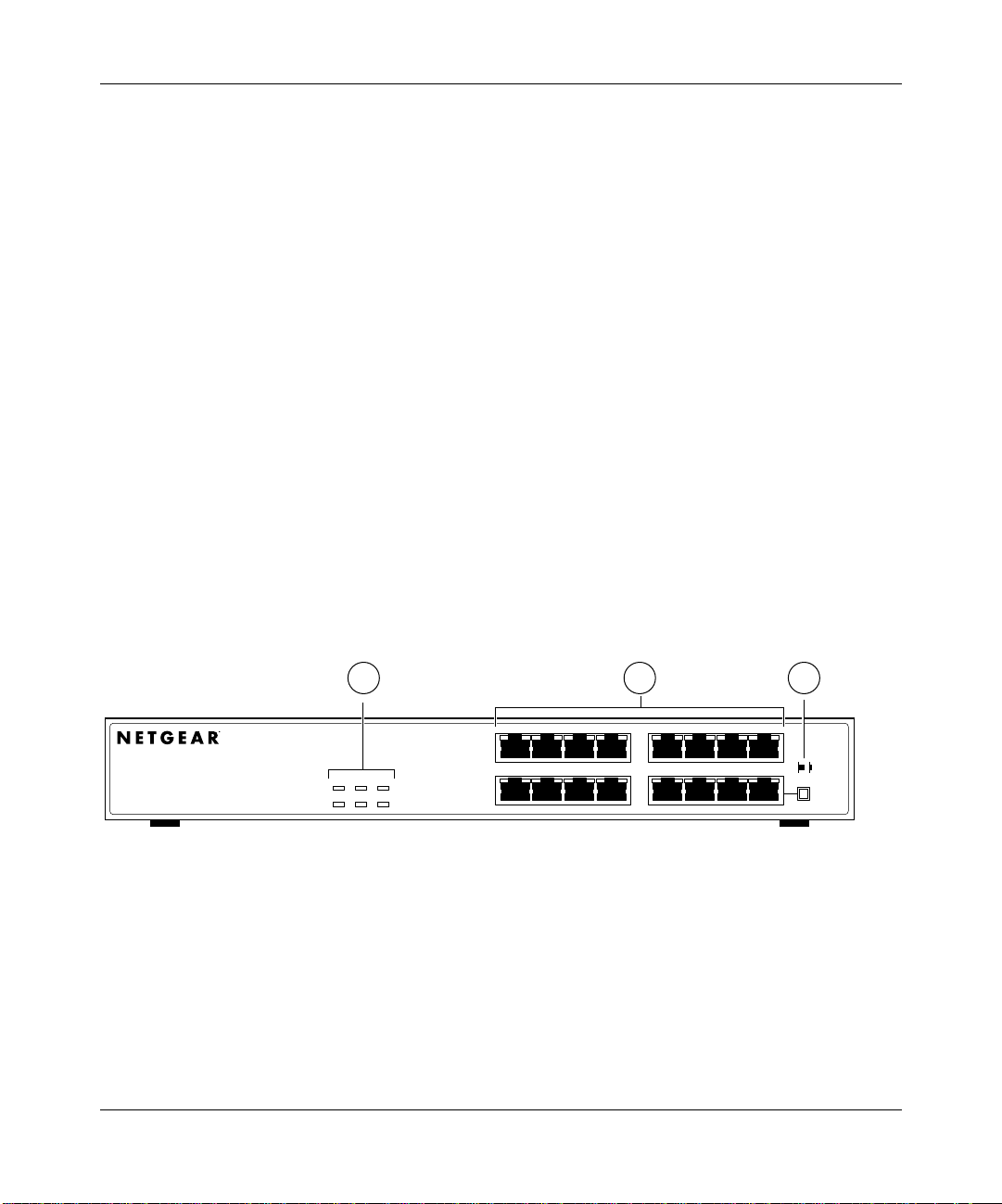
Front Panel
The front panel contains LEDs, 16 RJ-45 10BASE-T port connectors, and a Normal/Uplink push
button (Figure 2-1).
1 2 3
MODEL
PORT
16
10BASE-T
Ethernet Hub
BNCRxAUI
Power
Collision Partition Partition
Rx
1
Link/Rx Partition Link/Rx Partition
9
EN516
8
Normal/Uplink
16
7432
Key:
1 = LEDs (Power, BNC Rx, AUI Rx, Collision, BNC Partition, and AUI Partition)
2 = RJ-45 ports with Link/Rx and Partition LEDs on each port
3 = Normal/Uplink push button
Figure 2-1. Front panel of the Model EN516 hub
Physical Description 2-1
Page 14

Installation Guide for the Model EN516 Ethernet Hub
LED Indicators
There are six LEDs on the front panel of the hub and two on each port connector that allow you to
identify:
• Status of the hub AC power supply
• Operational status of the hub
• Collision occurrence on an Ethernet segment indicating activity level
• Partitioning of a port as a result of excessive collision occurrence
• Data utilization of the Ethernet segment in a standalone hub or a stack of hubs
• Link and receive activity status for all ports in the hub
Table 2-1 describes each LED on the front panel of the hub.
Table 2-1. LED descriptions
Label Color Activity Description
Power Green On Power is supplied to the hub.
BNC Rx Green Blinking There is incoming data on the BNC port.
AUI Rx Green Blinking There is incoming data on the AUI port.
Collision Yellow Blinking There is data collision on the network.
Note that occasional collisions are normal.
BNC Partition Yellow On The BNC port is being partitioned because
of excessive collisions, or when the BNC
port is not connected.
AUI Partition Yellow On The AUI port is being partitioned because of
excessive collisions.
Link/Rx (located on
top left corner of each
RJ-45 port)
Partition (located on
top right corner of each
RJ-45 port)
Green On
Blinking
Yellow On The port is being partitioned because of
The link between this port and the other
connecting port is good.
There is incoming data on the port.
excessive collisions.
2-2 Physical Description
Page 15

Installation Guide for the Model EN516 Ethernet Hub
RJ-45 Ports
The front panel of the Model EN516 hub provides 16 RJ-45 10BASE-T ports. Two LEDs, the
Link/Rx LED and the Partition LED, are positioned at the top corners of each RJ-45 connector.
Both LEDs are described in Table 2-1.
Normal/Uplink Push Button
The Normal/Uplink push button on the Model EN516 hub allows you to select Normal (MDI-X)
or Uplink (MDI) wiring for port 16, eliminating the need to use a crossover cable to connect
similarly wired devices. Port 16 is configured for Normal wiring when the push button is in the out
position. When the push button is pressed in, Port 16 is configured for Uplink wiring.
Ports 1 to 15 on the hub cannot be configured for Uplink wiring. If you are using one of these ports
to connect to a Normal port in another hub, you must use an RJ-45 crossover cable to connect the
two ports. See Figure B-2 for crossover cable information.
Physical Description 2-3
Page 16

Installation Guide for the Model EN516 Ethernet Hub
Rear Panel
The rear panel of the Model EN516 hub (refer to Figure 2-2) provides two ports, the AUI port and
the BNC port. You can use the AUI port with the appropriate transceiver to connect the hub to a
backbone network using thin coaxial cable, thick coaxial cable, fiber optic cable, or 10BASE-T
wiring. You can use the BNC port to connect to a backbone network or other PCs using thin
coaxial cable. The rear panel also includes an AC power receptacle. The hub accepts between 100
and 240 V AC, 50/60 Hz.
1 2 3
AUI
Key:
1 = AUI port
2 = BNC port
3 = AC power receptacle
BNC
Figure 2-2. Rear panel of the Model EN516 hub
100-240 VAC 50-60 Hz 0.15A
7147
2-4 Physical Description
Page 17

This chapter provides information on:
• Preparing the site
• Package contents
• Required tools
• Installing the hub
• Connecting the hub
• Completing and verifying the installation
Preparing the Site
Chapter 3
Installation
Before you begin installing the Model EN516 hub, prepare the installation site. Make sure the
operating environment meets the physical requirements of the hub. The ambient temperature must
be between 0°C and 40°C. The maximum relative humidity must not exceed 90%.
You can install the hub on a flat surface, such as a tabletop or shelf, or within a standard 19-inch
rack. You should ensure that the front and rear panel of all units to be connected are easily
accessible for connecting cables and power and for monitoring the LED indicators.
Package Contents
The package should contain the following items:
• Model EN516 hub
• This manual
Installation 3-1
Page 18

Installation Guide for the Model EN516 Ethernet Hub
• AC power cord
• Rack mount kit
• Four rubber pads for installation on a flat surface
• One BNC T-connector
• One BNC terminator
• Warranty and Owner Registration Card
Caution:
and ordinances.
Call your dealer if there are any wrong, missing, or damaged parts. Keep the carton, including the
original packing materials. Use them to repack the hub if there is a need to return it for repair.
Be sure to complete the Owner Registration Card and return it to NETGEAR to qualify for product
updates and product warranty registration.
Use the appropriate power cord as required by your national electrical codes
Required T ools
T o install the hub on a flat surf ace, you do not need any special tools. Ho we ver, to install the hub in
a rack, you need the following tools:
• #1 Phillips screwdriver to attach mounting brackets
• #2 Phillips screwdriver to tighten mounting screws
Installing the Hub
To install the Model EN516 hub, follow these steps:
1.
Unpack the hub.
Choose a location near the devices to be connected and close to an electrical outlet.
2.
Follow the instructions for installing the hub on a flat surface or in a rack.
3.
3-2 Installation
Page 19

Installation Guide for the Model EN516 Ethernet Hub
Installing the Hub on a Flat Surface
To install the hub on a flat surface such as a tabletop or shelf, follow these steps:
1.
Install self-adhesive pads on the bottom of the hub.
Peel off the protectiv e backing from the rubber pads and apply one at each marked location on
the bottom of the hub.
Set the hub on a tabletop or shelf so that it has at least 2 inches (5 cm) of space on all
2.
sides.
Restricted air flow could cause overheating.
Install any PCs, additional hubs, or other devices in your stack.
3.
For information on connecting the hub, refer to “Connecting the Hub” on page 3-4.
Installing the Hub in a Rack
To install the hub in a rack, follow these steps:
1.
Attach the mounting brackets (supplied in the rack mounting kit) to the sides of the hub
using the screws provided.
Hold a mounting bracket against each side of the hub, as shown in Figure 3-1, and align the
countersunk screw holes in the bracket with the bracket mounting holes in the hub. Use a #1
Phillips screwdriver to tighten the screws to secure each bracket.
2.
Attach the hub (with the mounting bracket) to the rack using two pan-head screws with
nylon washers.
Use a #2 Phillips screwdriver and tighten the screws to secure the hub to the rack.
Install any PCs, additional hubs, or other devices in your stack.
3.
For information on connecting the hub, refer to “Connecting the Hub” on page 3-4.
Installation 3-3
Page 20

Installation Guide for the Model EN516 Ethernet Hub
.
1
P
ower
D
ata
Collision
L
ink
RX
9
8
Link
RX
Normal/U
plin
k
16
7171
Figure 3-1. Installing mounting brackets to the hub and to a rack
Connecting the Hub
This section discusses connecting to the hub, cascading to multiple hubs, and connecting to other
NETGEAR products. For instructions on connecting to the ports or connecting to other
NETGEAR products, refer to the following sections:
•“Connecting to the RJ-45 Ports” on this page
•“Connecting to the BNC Port” on page 3-7
•“Connecting to the AUI Port” on page 3-9
•“Connecting to Other NETGEAR Products” on page 3-10
Connecting to the RJ-45 Ports
You can connect PCs, Apple Macintosh computers, UNIX workstations, and any device equipped
with a 10BASE-T Ethernet interface to the RJ-45 ports on the Model EN516 hub using twisted
pair Ethernet cables.
The twisted pair cable extended from an RJ-45 port (or UTP port) is called a twisted pair segment
and can be up to 100 m in length. The UTP ports, with the exception of port 16, are MDI-X (or
Normal) ports. To connect any of the Normal ports to a PC, a server, or another device with an
MDI (or Uplink) port, you can simply use a regular UTP cable. To connect any of the Uplink ports
to another Uplink port, use an RJ-45 crossover cable.
3-4 Installation
Page 21

Installation Guide for the Model EN516 Ethernet Hub
Port 16 is switchable between Normal (MDI-X) and Uplink (MDI) positions and should be
configured according to the following guidelines:
• Set the Normal/Uplink push button to the Normal position and use a straight-through cable if
the remote end of the cable is connected to an MDI-wired device such as a PC.
• Set the Normal/Uplink push button to the Uplink position and use a straight-through cable if
the remote end of the cable is connected to an MDI-X device such as a 10 Mbps or 100 Mbps
hub or repeater.
For further cabling guidelines, refer to Appendix B, “Cabling Specifications.”
Refer to the following illustrations for connecting to the RJ-45 ports and proceed to “Completing
and Verifying the Installation” on page 3-11.
Figure 3-2 illustrates a workstation connected to an RJ-45 port on the Model EN516 hub.
21
1
Power
Data Collision
Link RX
9
8
Link
RX
Normal/Uplink
16
34FA
Key:
1 = Network adapter card with RJ-45 connector
2 = UTP cable to Model EN516 hub
Figure 3-2. Connecting a workstation to an RJ-45 port on the Model EN516 hub
Ethernet specifications limit segments to 328 feet (100 m) in length.
Note:
Installation 3-5
Page 22

Installation Guide for the Model EN516 Ethernet Hub
Cascading refers to connecting hubs together to increase the number of ports, or the number of
users supported on the network. The RJ-45, BNC, or AUI ports can be used to cascade hubs
together. Figure 3-3 illustrates multiple hubs cascaded in a hierarchical star.
1
Model EN516 hub
432
Model EN516 hub Model EN516 hub Model EN516 hub
765
Model EN516 hub
A
Key:
1 = Model EN516 hub with the Normal/Uplink push button set to Normal position
2 through 7 = Model EN516 hub with the Normal/Uplink push button set to Uplink position
Model EN516 hub Model EN516 hub
B
30EA
Figure 3-3. Cascading multiple hubs in a hierarchical star through the RJ-45 ports
Ethernet specifications limit the number of hubs in any communication path to five
Note:
hubs, as shown in Figure 3-3. For example, when PC “A” communicates with PC “B,” the
communication path goes from hub 5 to hub 7, passing through hubs 2, 1, and 4.
3-6 Installation
Page 23

Installation Guide for the Model EN516 Ethernet Hub
Figure 3-4 illustrates multiple hubs cascaded in a daisy-chain style.
1
Model EN516 hub
2
Model EN516 hub
3
Model EN516 hub
000029EA
Key:
1 = Model EN516 hub with Normal/Uplink push button set to Normal position
2 and 3 = Model EN516 hub with Normal/Uplink push button set to Uplink position
Figure 3-4. Cascading multiple hubs daisy-chain style through the RJ-45 ports
Each twisted pair cable between two hubs is counted as one network segment.
Note:
When cascading hubs daisy-chain style through the twisted pair cable, stay within
Ethernet specifications and make sure the total hub count does not exceed five hubs.
Connecting to the BNC Port
The BNC port at the rear panel of the Model EN516 hub is used for connecting to a thin coaxial
segment. Y ou can connect servers, w orkstations, or other devices to the BNC port or se v eral Model
EN516 hubs as shown in Figure 3-5. By using the BNC port for cascading, you treat each
connected hub as just another node on the coaxial segment.
When using the BNC interface, follow these steps:
1.
Insert the BNC T-connector on the BNC port of the Model EN516 hub.
Connect the coaxial cable that leads from a device on the network to one of the
2.
self-locking ends of the BNC T-connector.
Installation 3-7
Page 24

Installation Guide for the Model EN516 Ethernet Hub
3.
Connect the coaxial cable from another device to the remaining end of the self-locking
BNC T-connector . If ther e ar e no mor e de vices to be connected, terminate the connection
with the 50 Ω terminator that is provided with the product.
4.
Proceed to “Completing and Verifying the Installation” on page 3-11.
Figure 3-5 illustrates three hubs cascaded through the BNC connector. The separation marks in the
coaxial cable between the two top hubs illustrate the incorporation of other devices and show that
interconnection is not limited to hubs.
1
2
1
7217
Key:
1 = 50 Ω terminators
2 = BNC T-connector
Figure 3-5. Cascading hubs through the BNC port
Ethernet specifications limit a BNC segment to 30 stations, specify a minimum of
Note:
0.5 m between any two stations, and limit segments to 600 feet (185 m) in length.
For further information about using coaxial cables, refer to Appendix B, “Cabling Specifications.”
3-8 Installation
Page 25

Installation Guide for the Model EN516 Ethernet Hub
Connecting to the AUI Port
The AUI port at the rear panel of the Model EN516 hub is normally used for connecting a thick
coaxial segment.
When using the AUI port, refer to Figure 3-6 and follow these steps:
Connect the AUI port on the hub to an external coaxial transceiver through an AUI
1.
transceiver cable.
With the right type of transceiver, you could use the AUI port to connect to most types of
network media, including 10BASE-T twisted pair , thin coaxial, thick coaxial, and 10B ASE-FL
fiber optic cables.
Disable the signal quality error (SQE) test function for each external transceiver
2.
connected to the AUI port.
Refer to your transceiver documentation for information about disabling the SQE test
function.
If the SQE test function is not disabled, the port is automatically partitioned.
Note:
3.
Proceed to “Completing and Verifying the Installation” on page 3-11.
1
2
3
4
Key:
1 = Cable termination device 3 = Thick coaxial cable
2 = 10BASE-5 transceiver 4 = Transceiver cable (AUI cable)
31EA
Figure 3-6. Cascading hubs through the AUI port
Installation 3-9
Page 26

Installation Guide for the Model EN516 Ethernet Hub
Ethernet specifications limit segments to 100 stations and 1,640 feet (500 m) in
Note:
length, and specify that the AUI cable between the hub and the transceiver is limited to
164 feet (50 m).
Connecting to Other NETGEAR Products
You can extend your network by connecting to an Ethernet switch, such as the NETGEAR Model
SW507 Ethernet Switch. Figure 3-7 illustrates power users on a 100 Mbps network using the
NETGEAR Model FE516 Fast Ethernet Hub and connecting to the 10 Mbps network through a
Model SW507 switch.
65421 3
Model FE516 hub
Model SW507 switch
Model EN516 hub Model EN516 hub Model EN516 hub
7228
Key:
1 = Workstations 4 = Server
2 = 100 Mbps connection 5 = NETGEAR Model SW507 Ethernet switch
3 = NETGEAR Model FE516 Fast 6 = 10 Mbps connection Ethernet hub
Figure 3-7. Connecting multiple NETGEAR products
3-10 Installation
Page 27

Installation Guide for the Model EN516 Ethernet Hub
Completing and Verifying the Installation
To complete the installation, connect the power cord first to the power entry receptacle on the hub
rear panel and then to the power outlet on the wall. When power has been applied to the hub, the
following conditions should exist:
• Green Power LED on the front panel is on.
• Yellow BNC Partition LED is on if the BNC port is not connected.
• Green Link/Rx LED on each connected port is on.
If there are any problems, refer to Chapter 4, “Troubleshooting.”
Installation 3-11
Page 28

Page 29

Chapter 4
Troubleshooting
This chapter provides information about troubleshooting the Model EN516 hub.
Front Panel LEDs
The Model EN516 hub provides 38 front panel LEDs for monitoring individual ports and hub
status. The power LED indicates when power is supplied to the hub.
The following sections describe the LEDs that are used for monitoring the Model EN516 hub.
Collision LED
The yellow Collision LED indicator blinks when there is data collision on the network. Data
collision is normal on Ethernet networks and occurs when two or more devices transmit data on
the network simultaneously. The devices that caused the collision automatically back off and then
retry transmission at different intervals until the transmission succeeds.
Excessive collisions can result for several reasons. Some factors that can contribute to excessive
collisions are:
• The network is extremely busy.
• Defective devices are connected on the network that cannot detect network traffic or collisions.
• Wrong cables are being used.
Many home telephone cables can cause a collision condition because the cable is not
constructed with twisted pair wires and cannot be used in place of UTP cables.
• Wrong cables are being used for connecting MDI (or Uplink) and MDI-X (or Normal) wired
devices.
Troubleshooting 4-1
Page 30

Installation Guide for the Model EN516 Ethernet Hub
• Defective connectors are being used.
For further information on pin assignment and cable specifications, refer to Appendix B, “Cabling
Specifications,” and Appendix C, “Connector Pin Assignments.”
Link/Rx LED for the RJ-45 Ports
The green Link/Rx LED on each RJ-45 port turns on when a link is established successfully
between the hub and a PC or other device. It is off when there is no data link and/or the cable is not
connected. If the Link/Rx LED is not on after cabling has been installed, check for a bad cable,
cable pairs that are not correctly wired, or loose connectors. Also check to see whether or not there
is power for both the hub and the Ethernet transceiver on the connected PC or other device.
The green Link/Rx LED indicator blinks when there is data reception on the port.
AUI Rx LED and BNC Rx LED for the AUI and BNC Ports
The green AUI Rx LED and BNC Rx LED blink when there is data reception on the AUI or BNC
port.
Partition LED for the RJ-45 Ports
The yellow Partition LED on each of the RJ-45 ports turns on when the port is being partitioned
after 32 continuous collisions are detected on the connected segment. After the first good packet
without a collision is received, the yello w Partition LED on the RJ-45 port turns of f, and the port is
reconnected.
Partition LED for the BNC Port
The yellow Partition LED indicator turns on when the BNC port has been partitioned after 32
continuous collisions are detected on the BNC port. After the first good packet without a collision
is received, the yellow Partition LED on the BNC port turns off, and the port is reconnected.
The BNC port is partitioned when there are one or more of the following conditions:
• No coaxial cable connected to the BNC port
• Faulty cable or connectors
• Excessive collisions on the connected segment
4-2 Troubleshooting
Page 31

Installation Guide for the Model EN516 Ethernet Hub
• Disconnected point somewhere along the coaxial cable length
• Segment that is not terminated with a 50 Ω terminator on both ends
Check all connectors along the cable length. If the segment is not terminated, terminate both ends
with 50 Ω terminators.
Partition LED for the AUI Port
When the AUI port is connected with a 10BASE-T twisted pair or 10BASE-FL fiber optic
transceiver , the P artition LED turns on after 32 continuous collisions are detected on the connected
segment. After the first good packet without a collision is received, the Partition LED on the AUI
port turns off, and the port is reconnected.
If the port is connected with coaxial media type AUI transceivers, the LED functions the same way
as described in the previous section, “Partition LED for the BNC Port.” Be sure that the coaxial
transceiver is functioning properly and that the signal quality error (SQE) test has been disabled.
Installation
Verify that all system components have been properly installed. If one or more components are
malfunctioning, isolate the defective component(s) by testing them in a different environment
where all other components are functioning properly.
Cabling
Be sure all cable connectors are securely positioned in the required ports. Straight-through cables
should be used for all standard twisted pair connections.
Make sure all devices are still connected to the network. The equipment might have been
accidentally disconnected.
To verify that the cabling is correct, refer to Appendix B, “Cabling Specifications.”
Troubleshooting 4-3
Page 32

Installation Guide for the Model EN516 Ethernet Hub
Network Interface Cards
Make sure the network interface cards installed in the workstations are in working condition.
Configuration
If problems occur after altering the network configuration, restore the original connections and
determine the problem by implementing the new changes, one procedure at a time. Ensure that
cable distances, repeater limits, and other physical aspects of the installation do not exceed the
recommendations.
Hub Integrity
If required, verify the integrity of the hub by resetting it. Turn off the power to the switch and then
turn the power to the switch back on. If the problem continues and you have completed all the
preceding diagnoses, contact Customer Support. See page iii for the phone number of Customer
Support in your area.
4-4 Troubleshooting
Page 33

Appendix A
Technical Specifications
This appendix provides technical specifications for the NETGEAR Model EN516 Ethernet Hub.
General Specifications
Network Protocol and Standards Compatibility
IEEE 802.3 10BASE-T, 10BASE-2, 10BASE5 Ethernet
IEEE 802.3 CSMA/CD
Data Rate
10 Mbps, Manchester encoded
Interface
16 10BASE-T ports (RJ-45)
1 BNC 10BASE-2 port
1 AUI port (15 pin D-type)
Power Adapter
100-240V, 50/60 Hz (auto selection)
Electrical Specifications
Power Consumption: 0.15 A maximum
Physical Specifications
Width: 13.0 inches (33 cm)
Height: 1.7 inches (4.3 cm)
Depth: 8.0 inches (20.3 cm)
Weight: 4.8 lb (2.2 kg)
Technical Specifications A-1
Page 34

Installation Guide for the Model EN516 Ethernet Hub
Environmental Specifications
Operating temperature: 0° C to 40° C (32° F to 104° F)
Operating humidity: 90% maximum relative humidity, noncondensing
Electromagnetic Emissions
CE mark, commercial
FCC Part 15 Class A
EN 55 022 (CISPR 22), Class B
VCCI Class 1 ITE
Electromagnetic Susceptibility
CE mark, commercial
Electrostatic discharge (ESD): IEC 801-2, Level 2/3/4
Radiated electromagnetic field: IEC 801-3, Level 2
Electrical fast transient/burst: IEC 801-4, Level 2
Electrical surge: IEC 801-5, Level 2
Safety Agency Approvals
CE mark, commercial
UL listed (UL 1950)
CSA certified (CSA 22.2 #950)
TUV licensed (EN 60 950)
A-2 Technical Specifications
Page 35

Appendix B
Cabling Specifications
This appendix provides specifications for cables used with the NETGEAR Model EN516 Ethernet
Hub.
Cable Specifications
For 10 Mbps connections, Category 3, 4, or 5 cables can be used. NETGEAR highly recommends
using Category 5 cable to avoid unnecessary e xpense or confusion if you upgrade to F ast Ethernet.
Table B-1 lists the electrical requirements of Category 3, 4, and 5 cables.
Table B-1. Electrical requirements of Category 3, 4, and 5 cables
Specification Category 3 Category 4 Category 5
Number of pairs Four Four Four
Impedance 100 Ω ± 15% 100 Ω ± 15% 100 Ω ± 15%
Mutual capacitance
at 1 KHz
Maximum attenuation
(dB per 100 m, at 20° C)
NEXT loss
(dB minimum)
≤6.6 nF per 100 m ≤5.6 nF per 100 m ≤5.6 nF per 100 m
at 4 MHz: 5.6
at 10 MHz: 9.8
at 16 MHz: 13.1
at 4 MHz: 32
at 10 MHz: 26
at 16 MHz: 23
at 4 MHz: 4.3
at 10 MHz: 7.2
at 16 MHz: 8.9
at 4 MHz: 47
at 10 MHz: 41
at 16 MHz: 38
at 16 MHz: 8.2
at 31 MHz: 11.7
at 100 MHz: 22
at 16 MHz: 44
at 31 MHz: 39
at 100 MHz: 32
Cabling Specifications B-1
Page 36

Installation Guide for the Model EN516 Ethernet Hub
Twisted Pair Cables
For two devices to communicate, the transmitter of each device must be connected to the receiver
of the other device. The crossover function is usually implemented internally as part of the
circuitry in the device. Most repeaters and switch ports are media-dependent interfaces with
crossover ports, referred to as MDI-X or Normal ports. Computers and workstation adapter cards
are usually media-dependent interface ports, referred to as MDI or Uplink ports. Refer to the
installation instructions in Chapter 3, “Installation,” for appropriate cable use and connection.
Figure B-1 and Figure B-2 illustrate the use of straight-through and crossover twisted pair cables.
1
Tx
2
1
3
Rx
6
Key:
1 = Uplink or MDI port
2 = Normal or MDI-X port
Figure B-1. Straight-through twisted pair cable
1
Rx
2
1
3
Tx
6
1
Rx
2
2
3
Tx
6
7181
1
Rx
2
2
3
Tx
6
7182
Key:
1 = Normal or MDI-X port
2 = Normal or MDI-X port
Figure B-2. Crossover twisted pair cable
B-2 Cabling Specifications
Page 37

Installation Guide for the Model EN516 Ethernet Hub
50 Ω Coaxial Cable
The 50 Ω coaxial cable, the BNC T-connector, and the 50 Ω terminator, allo w a user to construct a
10BASE-2 network. Table B-2 lists the specifications of 10BASE2 (ThinNet) RG 58 A/U or RG
58 C/U coaxial cable.
Table B-2. Specifications of 10BASE2 (ThinNet) RG 58 A/U or RG 58 C/U
coaxial cable
Characteristic
impedance
50 +/-2 Ω <8.5 db @ 10 MHz
Attenuation
(185 m cable)
<6.0 db @ 5 MHz
Transfer
impedance
20 mΩ @ 1 MHz
100 mΩ @ 10 MHz
500 mΩ @ 100 MHz
DC loop
resistance
50 mΩ /meter
The Ethernet specifications limit segments to 30 stations, specify a minimum of 0.5 m between
any two stations, and limit segments to 600 feet (185 m) in length.
AUI Cable
The AUI cable connects the AUI port on the Model EN516 hub to a transceiver. The Ethernet
specifications limit the cable length to 164 ft (50 m). Table B-3 lists the specifications of AUI
cable.
Table B-3. Specifications of AUI cable
Electrical characteristic AUI cable specifications
Nominal dc resistance <1.75 Ω per conductor
Pair-to-pair balanced crosstalk Minimum 40 dB attenuation from 5 MHz to 10 MHz
Differential characteristic impedance 78 +/- 5 Ω at 10 MHz
<3 Ω difference between pairs
Transfer impedance <10 mΩ @ 500 KHz
<3 mΩ @ 2 MHz
<3 mΩ @ 10 MHz
<30 mΩ @ 100 MHz
Attenuation <3 dB from 5 MHz to 10 MHz
Timing jitter <1.0 ns introduced by the cable system
Total signal delay <257 ns
Cabling Specifications B-3
Page 38

Page 39

Appendix C
Connector Pin Assignments
This appendix provides information on the RJ-45, AUI, and BNC connectors that are used for the
NETGEAR Model EN516 Ethernet Hub.
RJ-45 Connector
The RJ-45 connector is used to connect workstations, hubs, and switches through unshielded
twisted pair cable. The RJ-45 connector accepts four-pair Category 3 or Category 5 UTP cable.
Only two pairs are used for 10BASE-T wiring. Figure C-1 illustrates the RJ-45 connector.
18
7177
Figure C-1. RJ-45 connector
Connector Pin Assignments C-1
Page 40

Installation Guide for the Model EN516 Ethernet Hub
Table C-1 lists the pin assignments for the RJ-45 connector.
Table C-1. RJ-45 connector pin assignments
Pin
1 Input Receive Data + Output Transmit Data +
2 Input Receive Data - Output Transmit Data 3 Output Transmit Data + Input Receive Data +
6 Output Transmit Data - Input Receive Data 4, 5, 7, 8 Not used Not used
Normal assignment
on ports 1 to 15
Uplink assignment
on port 16
AUI Connector
The AUI connector for the Model EN516 hub connects the hub through an external
transceiver to other devices. An inter-repeater fiber link for 10BASE-F or FOIRL are
examples of such applications. Figure C-2 illustrates the AUI connector pin assignments.
8
15
1
9
7176
Figure C-2. AUI connector pin assignments
C-2 Connector Pin Assignments
Page 41

Installation Guide for the Model EN516 Ethernet Hub
Table C-2 lists the AUI connector pin assignments.
Table C-2. AUI connector pin assignments
Pin Signal
1, 4, 11, 14, 15 Ground
2 CI-A
3 DO-A
5 DI-A
6 + 12V DC return
7, 8 Not used
9 CI-B
10 DO-B
12 DI-B
13 + 12V DC (500 mA
maximum)
BNC Connector
The BNC connector for the Model EN516 hub supports 10 Mbps data transmission and connects
the hub to other devices. Figure C-3 illustrates the parts of the BNC connector.
1
Key:
1 = Center conductor
2 = Ground shield
Figure C-3. BNC connector
Connector Pin Assignments C-3
2
7201
Page 42

Installation Guide for the Model EN516 Ethernet Hub
BNC T-Connector and 50 Ω T erminator
The BNC port on the Model EN516 hub, with the BNC T-connector and the 50 Ω terminator, is
used for connecting to a thin coaxial segment. Figure C-4 illustrates the BNC T-connector and
50 Ω terminator . F or information on connecting to the BNC port, refer to Chapter 3, “Installation,”
and Appendix B, “Cabling Specifications.”
50
OHM
7178
Figure C-4. 50 Ω terminator and BNC T-connector
C-4 Connector Pin Assignments
Page 43

Numerics
10BASE2 coaxial cable specifications (table)
B-3
A
attachment unit interface. See AUI
AUI cable specifications (table) B-3
AUI connector pin assignments (table) C-2
AUI Partition LED 2-2, 4-3
AUI port
cascading hubs through 3-9
connecting to 3-9
description 2-4
AUI Rx LED 2-2, 4-2
B
BNC
50 ohm terminator C-4
connector C-3
T-connector C-4
BNC Partition LED 2-2, 3-11, 4-2
BNC port
cascading hubs through 3-7
connecting to 3-7
description 2-4
BNC Rx LED 2-2, 4-2
Index
C
cable
10BASE-2 coaxial cable specifications (table)
B-3
50-ohm coaxial B-3
AUI B-3
Category 3 B-1
Category 4 B-1
Category 5 B-1
crossover twisted pair 3-4, B-2
RG 58 A/U specifications (table) B-3
RG 58 C/U coaxial B-3
specifications B-1
straight-through twisted pair 3-5, B-2
troubleshooting 4-3
cascading
daisy-chain style 3-7
hierarchical star style 3-6
ports 3-4 to 3-9
Certificate of the Manufacturer iii
coaxial cable specifications (table) B-3
Collision LED 2-2, 4-1
configuration, troubleshooting 4-4
connecting
ports 3-4 to 3-9
to MDI (or Uplink) device B-2
to MDI (or Uplink) port 3-4, B-2
to MDI-X (or Normal) port 3-4
Index 1
Page 44

Installation Guide for the Model EN516 Ethernet Hub
connector
AUI pin assignments (table) C-2
BNC C-3
BNC-T C-4
RJ-45 pin assignments (table) C-1
crossover twisted pair cable B-2
customer support iii
D
daisy-chain cascade 3-7
F
FCC statement ii
features 1-1
front panel 2-1
H
hierarchical star cascade 3-6
I
installation
cascading ports 3-4 to 3-9
completing 3-11
connecting ports 3-4 to 3-9
connecting to NETGEAR products 3-10
daisy-chain style 3-7
in a rack 3-3
network interface cards 4-4
on a flat surface 3-3
package contents 3-1
tools required 3-2
troubleshooting 4-3
verifying 3-11, 4-4
L
LEDs
AUI Partition 2-2, 4-3
AUI Rx 2-2, 4-2
BNC Partition 2-2, 3-11, 4-2
BNC Rx 2-2, 4-2
Collision 2-2, 4-1
description (table) 2-2
Power 2-2, 3-11, 4-1
RJ-45 Link/Rx 2-2, 3-11, 4-2
RJ-45 Partition 2-2
troubleshooting 4-1
M
MDI device, setting Normal/Uplink push button
2-3
MDI port, connecting to B-2
MDI-X device, setting Normal/Uplink push
button 2-3
MDI-X port, connecting to B-2
N
network interface cards, troubleshooting 4-4
Normal/Uplink push button
setting for MDI 2-3
setting for MDI-X 2-3
2 Index
Page 45

Installation Guide for the Model EN516 Ethernet Hub
P
package contents 3-1
ports
See also AUI
See also BNC
See also RJ-45
AUI 2-4
BNC 2-4
cascading 3-4 to 3-9
connecting 3-4 to 3-9
RJ-45 2-3
using transceivers to connect AUI 3-9
Power LED 2-2, 3-11, 4-1
R
rear panel 2-4
RG 58 A/U coaxial cable specifications (table)
B-3
RG 58 C/U coaxial cable B-3
RJ-45 connector
pin assignments (table) C-1
RJ-45 Link/Rx LED 2-2, 3-11, 4-2
RJ-45 Partition LED 2-2
RJ-45 ports
cascading hubs through 3-4
configuring port 16 3-5
connecting Apple Macintosh computers 3-4
connecting PCs 3-4
connecting UNIX workstations 3-4
description 2-3
using crossover cable 3-4
using straight-through cable 3-5
T
technical specifications A-1
technical support iii
troubleshooting
cable 4-3
configuration 4-4
installation 4-3, 4-4
LEDs 4-1
network interface cards 4-4
U
unshielded twisted pair cable. See RJ-45
W
warranty 1-2
W orld W ide Web iii
S
site preparation 3-1
straight-through twisted pair cable B-2
Index 3
Page 46

 Loading...