

Page 1
Page 2
Start Here
Congratulations on your purchase of the NETGEAR™ Model EN104, Model EN108, or Model
EN116 Ethernet hub. The hubs deliver standards-based, plug-and-play networking solutions for
small businesses, home offices, and low-density workgroups of larger companies
.
In this installation guide, all three hubs are referred to collectively as the Model EN104/EN108/
EN116 hub. Each hub is listed individually when information is provided that refers to a specific
model.
Features
The Model EN104/EN 108/EN116 hub has the following features:
• Four (on t he Mod el EN104 h ub), e igh t (on t he Mod el EN1 08 hu b) , and si xt een (on the Model
EN116 hub) vi sta 10BASE-T network ports (RJ-45) that provide 10 megabit per second
(Mbps) networking using simple unshielded tw isted pair (UTP) wiring
• Built-in LED indicators for at-a-glance status checks by vista networks ports
• AUI (not on the Model EN104 hub) or coaxial BNC backbone support for connecting to an
existi ng Ethernet se gment or external transceiv er, or for network expansion by connecting
multiple hubs together using twisted pair or coaxial cabling
• Uplink port for connecting to other hubs using simple straight-through cables
• Clear front-panel light-emitting diode (LED) indicato rs to monitor overall hub status
• Plug-and-play installation with no software to configure
• Complete hub functions including pack et retimin g , collision detection, preamble
regener ation, and fragment extension
• Automatic partitioning and r econnection of a port that has excessi ve colli sions or is jabbering
• Automatic polarity detectio n for recognizing and corr ecting incor rect polarity on the rec eive
pair
• Compact design, enabling easy tabletop or rack-mounting installation
• External power adapter
• Limited five -year warranty on the uni t and one-year warranty on the power supply
Package Con te nt s
Model EN104 hub
Pwr
Col
Pwr
Col
1234 5678
Mounting kit
Installation guide,
Warranty & Owner
Registration Card,
Support Information
Card
Model EN104/EN108/EN11 6 Ethernet Hub Installation Gui de
or
10 BASE-T HUB
EN104
LINK Rx
or
Model EN116 hub
10 BASE-T HUB
EN116
1234 5678
Model EN108 hub
10 BASE-T HUB
EN108
Pwr
Col
1234 5678
LINK Rx
LINK Rx
Power
adapter
and cord
8731FA
Page 3
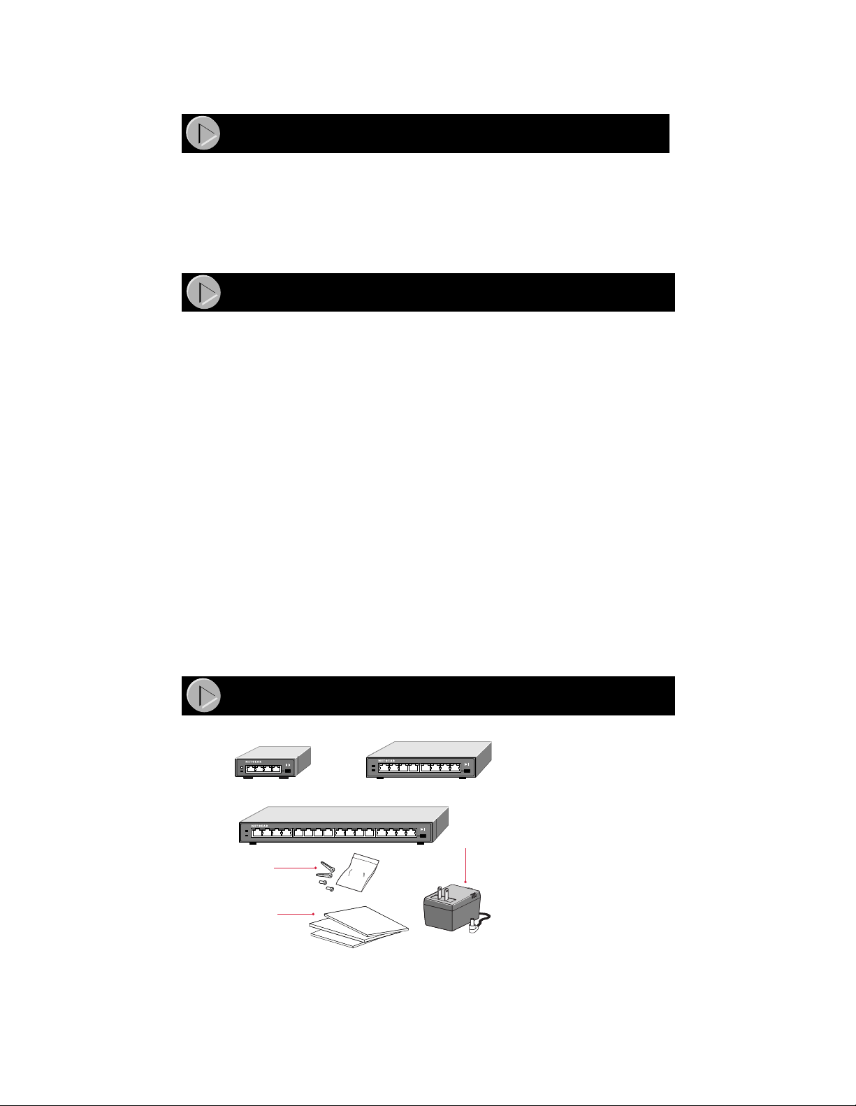
Verify that your package contains the following:
• Model EN104 hub, Model EN108 hub, or Model EN116 hub
• Mounting kit (for wall installation)
• BNC T-connector and BNC 50 Ω terminator (only if you have purchased the Model EN108
hub or the Model EN116 hub)
• This insta llation guide
• Warranty & Owner Registration Card
• Support Inf ormation Card
• Power adapter and cord
Product Illustration
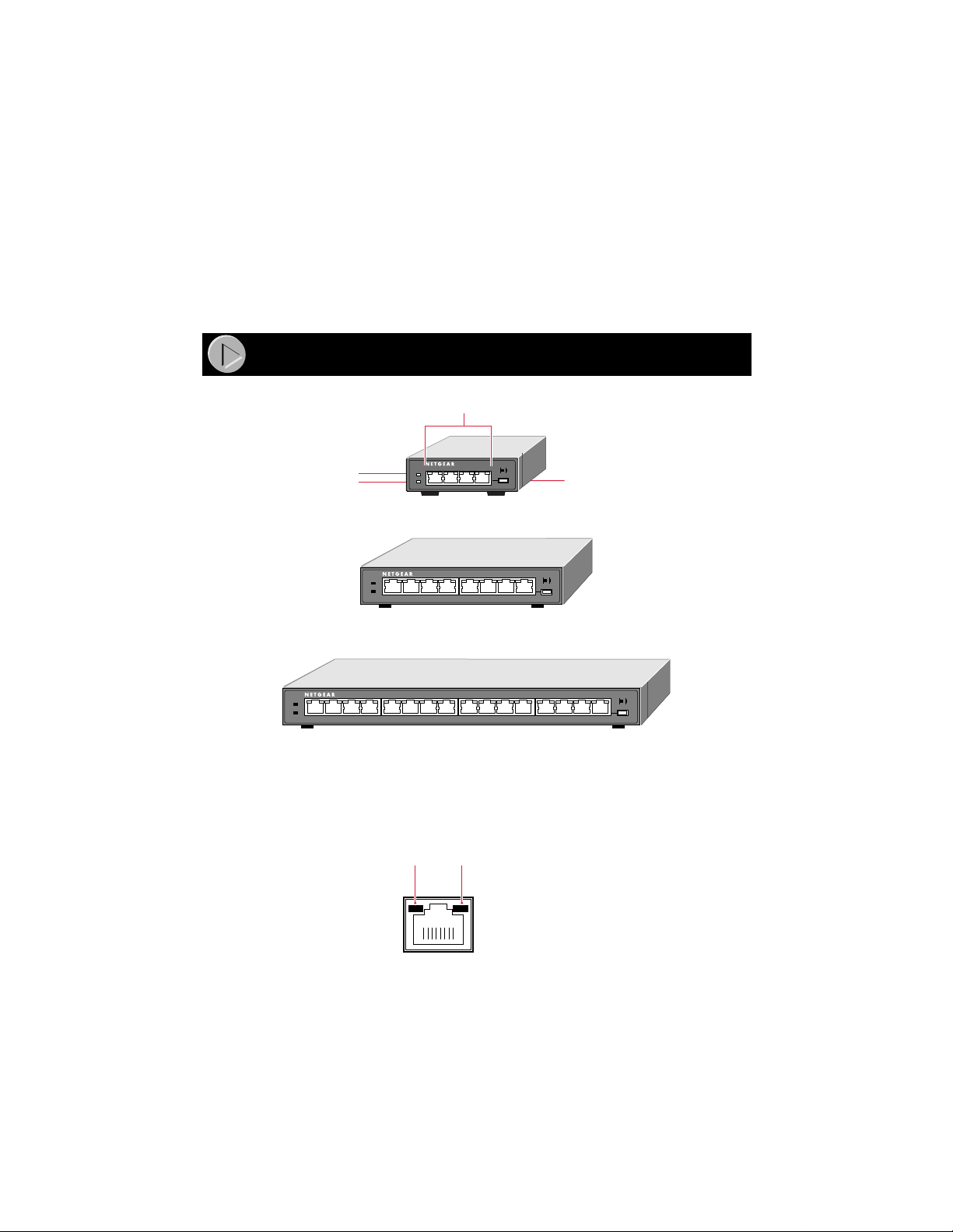
Front Panel of the Model EN104 hub
10BASE-T ports
10 BASE-T HUB
EN104
Pwr (Power)
Col (Collision)
Pwr
Col
Front Panel of the Model EN108 hub
LINK Rx
Normal/Uplink
push button
10 BASE-T HUB
Pwr
Col
EN108
1234 5678
LINK Rx
Front Panel of the Model EN116 hub
10 BASE-T HUB
Pwr
Col
EN116
1234 5678
1234 5678
LINK Rx
8732FA
Vista 10BASE-T Network Ports with Built-in LEDs
The front panel of the Model EN104 hub has four RJ-45 10BASE-T ports, the Model EN108 hub
has eight RJ-45 10BASE-T ports, and the Model EN116 hub has sixteen RJ-45 10BASE-T ports.
Two LEDs—the Link LED and the Rx LED—are built into each 10BASE-T port.
Link
LEDRxLED
8724EA
Model EN104/EN108/EN11 6 Ethernet Hub Installation Gui de
Page 4
LEDs
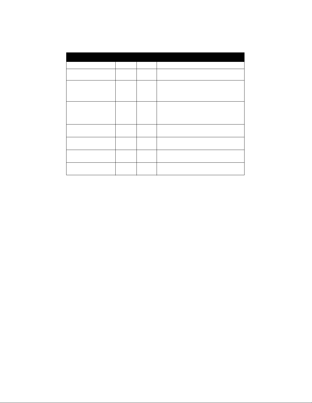
The table below describes the activity of the LED s.
Label Color Activity Description
Pwr (Power) Green On Power is supplied to the hub.
Col (Colli si on ) Amber Blinki ng Data c ol li si on i s occ ur rin g o n t he ne tw ork. No te
Link
(located on the top left
corn er of ea ch vista
10BASE-T por t )
Rx
(located on the top right
corn er of ea ch vista
10BASE-T por t )
Active
(for BNC)
Rx
(for BNC)
Active
(for AUI)
Rx
(for AUI)
Green On T he link between this port and the connect ed
Green Blinking There is incoming data on the port.
Green On The link between the BNC port and the
Green Blinking There is incoming data on the BNC port.
Green On The link between the AUI port and the
Green Blinking There is incoming data on the AUI port.
that oc casional collisions are normal.
device is good.
connected device is good.
connected device is good.
Normal/Uplink Push Button
The Normal/Uplink push button allows you to select Normal (MDI-X) wiring for direct PC
connection. The push button also allows you to select Uplink (MDI) wiring for connection to a
hub or a switch through port 4 on the Model EN104 hub, port 8 on the Model EN108 hub, or
port 16 on the Model EN116 hub. This uplink configuration eli minates the need to use a crossover
cable. The other 10BASE-T ports are pe rm anently configured for normal wiring for connection to
a PC.
Rear Panel
The rear panel of the hub has a BNC port that you can use to connect to a backbone network or
other PCs using thin coaxial cable.
The rear panel of the Model EN108 hub and the Model EN116 hub also has an AUI port in
addition to the BNC port. You can use the AUI port w ith the appropriate transceiver to connect the
hub to a backbone network using thin coaxial cable, thick coaxial cable, fiber optic cable, or
10BASE-T wiring.
Model EN104/EN108/EN11 6 Ethernet Hub Installation Gui de
Page 5
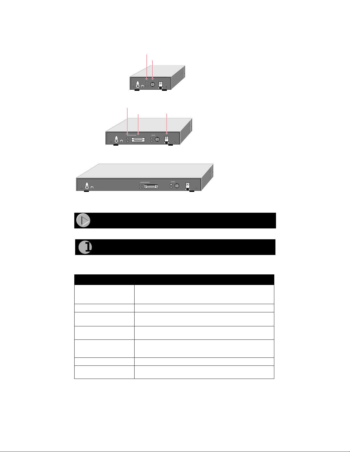
The rear panel also includes a DC power receptacle.
The rear panel also includes a DC power receptacle.
BNC port LEDs
BNC port LEDs
BNC port
BNC port
12Vdc 1.2A
12Vdc 1.2A
Active
Active
BNC
BNC
Rx
Rx
– +
– +
Rear Panel of the Model EN104 hub
Rear Panel of the Model EN104 hub
AUI port LEDs
AUI port LEDs
AUI port
AUI port
AUI
AUI
Active
Active
Active
Rx
Rx
Rear Panel of the Model EN108 hub
Rear Panel of the Model EN108 hub
Rear Panel of the Model EN116 hub
Rear Panel of the Model EN116 hub
Active
Rx
Rx
AUI
AUI
Active
Active
Rx
Rx
12Vdc 1.2A
12Vdc 1.2A
BNC
BNC
– +
– +
Power receptacle
Power receptacle
BNC
BNC
Active
Active
Rx
Rx
12Vdc 1.2A
12Vdc 1.2A
– +
– +
8738FA
8738FA
Installation Pr ocedures
Installation Pr ocedures
Prepare the Site
Prepare the Site
Before you begin installing your hub, prepare the installation site. Make sure your operating
Before you begin installing your hub, prepare the installation site. Make sure your operating
envi ronment meets the operating environment requirements of the equipment.
envi ronment meets the operating environment requirements of the equipment.
Characteristic Requirement
Characteristic Requirement
Temperature Ambien t temperature between 0° and 40° C (32° and 104° F).
Temperature Ambien t temperature between 0° and 40° C (32° and 104° F).
No nearby heat sources such as direct sunlight, warm air exhausts,
No nearby heat sources such as direct sunlight, warm air exhausts,
or heaters.
or heaters.
Opera ting humidity Maximum relative humidity of 90%, noncondensing.
Opera ting humidity Maximum relative humidity of 90%, noncondensing.
Ventilation Minimu m 2 inches (5.08 cm) on all sides for cooling.
Ventilation Minimu m 2 inches (5.08 cm) on all sides for cooling.
Adequate airflow in roo m or wiring cl oset.
Adequate airflow in roo m or wiring cl oset.
Opera ting conditions At least 6 feet (1.83 m) to nearest source of electromagnet ic noise
Opera ting conditions At least 6 feet (1.83 m) to nearest source of electromagnet ic noise
Service access Minimum 12 inches (19.68 cm) front and back for service access
Service access Minimum 12 inches (19.68 cm) front and back for service access
Power Adequate power source within 6 feet (1.83 m).
Power Adequate power source within 6 feet (1.83 m).
Wiring hardware Wiring hardware, such as punchdown blocks or patch panels,
Wiring hardware Wiring hardware, such as punchdown blocks or patch panels,
(such a s photocopy machine or arc welder).
(such a s photocopy machine or arc welder).
and maintenance. Front and back clearance for cables and wiring
and maintenance. Front and back clearance for cables and wiring
hardware such as punchdown blocks.
hardware such as punchdown blocks.
should be complete bef ore installing the hub.
should be complete bef ore installing the hub.
Model EN104/EN108/EN11 6 Ethernet Hub Installation Gui de
Page 6

Install the Hub
To install your hub on a flat surface, you do not need any special tools. Be sure the hub is
positio ned with at least 2 inches of space on all sides for ventilation.
To install the hub on a wall, measure the distance between the mounting hole on the back of the
hub and mark the wall to match the location of the mounting holes on the hub. At the marked
location, screw into the wall the two screws that you received with the mounting kit included in
your package contents. Be sure to choose a location that is near the devices to be connected, is
close to an electrical outlet, and provides at least 2 inches of space all around the hub for
ventilation.
Connect a PC to the Hub
You can connect PCs, Apple Macintosh computers, UNIX workstations, or any device equipped
with a 10BASE-T Ether net interf ace to the RJ-45 ports on your hub by using twisted pair Ether n et
cables.
To connect any of the RJ-45 ports on your hub to a PC, use a regular straight-through UTP cable.
If you are connecting using port 4 on the Model EN104 hub, port 8 on the Model EN108 hub, or
port 16 on the Model EN116 hub, set the Normal/U plink push button to Normal .
(The Model EN108 hub is
shown in the illustration.)
Pwr
Col
1
2
3
4
5
Normal/Uplink
6
7
8
8734FA
Note:
Ethernet specifications limit the cable le ngth between your PC or server and
the hub to 328 feet (100 meters) in length.
Connect the Hub to a NetworkConnect the Hub to a Network
Cascading refers to connecting hubs together to increase the number of ports or the number of
users supported on the network. The 10BASE-T ports can be used to cascade hubs together.
The twisted pair cable extended from a 10BASE-T port (or UTP port) is called a twisted pair
segment and can be up to 100 meters (m) in length. The 10BASE-T ports, with the exception of
port 4 on the Model EN104 hub, port 8 on the Model EN108 hub, or port 16 on the Model EN116
hub, are MDI-X (or Norm al) ports . Use the following table as a guide for selecting the appropriate
network ca ble.
Model EN104/EN108/EN11 6 Ethernet Hub Installation Gui de
Page 7

Connecting Port
on the Hub
Connecting Device Cable Used
Model EN104 hub:
Ports 1–3 PC, server, or router Straight-through cable
Ports 1– 3 Hub or swit c h Crossover ca ble
Model EN108 hub:
Ports 1–7 PC, server, or router Straight-through cable
Ports 1– 7 Hub or switch Crossover ca ble
Model EN116 hub:
Ports 1–15 PC, server, or router Straight-through cable
Ports 1– 15 Hub or switch Crossover ca ble
Set the Normal/Uplink Push Button
If you are connecting to port 4 on the Model EN104 hub, port 8 on the Model EN108 hub, or port
16 on the Model EN116 hub, use the following table. Determine the type of cable to use and how
to set the Normal/Uplink push button.
Connecting Port Conne cti ng D evice Cable Used
Port 4, port 8, or port 16
set to Norma l
Port 4, port 8, or port 16
set to Uplink
PC, server, or router Straight-through cable
Hub or switch Straight-through cable
Cascade the Hub
The following illustration shows cascading hubs together in a hierarchical star through
the 10BASE-T ports and indicates the setting of the Normal/Uplink push button on each hub.
Model EN116 hub
10 BASE-T HUB
Model EN108 hub
TP
10 BASE-T HUB
EN108
Pwr
Col
1234 5678
EN116
Pwr
Col
1234 5678
1234 5678
Uplink
LINK Rx
Model EN108 hub
TP
10 BASE-T HUB
EN108
Pwr
Col
1234 5678
Normal
Uplink
Model EN104 hub Model EN104 hub
UplinkUplink
AB
Note:
Ethernet specifications limit the number of hubs with twisted pair links in any
8735FA
communic ation path to five, as shown in the example. When PC “A” com m unicates
with PC “B,” th e com m unication path goes from hub 4 to hub 2, to hub 1, to hub3,
and then to hu b 5 (or fiv e paths).
Model EN104/EN108/EN11 6 Ethernet Hub Installation Gui de
Page 8

The following illustration shows cascading hubs together daisy-chain style and indicates the
setting of the Normal/Uplink push button on each hub.
Model EN104 hub
10 BASE-T HUB
EN104
Pwr
Col
LINK Rx
Normal
Model EN108 hub
10 BASE-T HUB
Pwr
Col
EN108
1234 5678
LINK Rx
Uplink
Model EN116 hub
10 BASE-T HUB
Pwr
Col
EN116
1234 5678
1234 5678
LINK Rx
Uplink
8733FA
Connect to a Network Using the BNC Port
The BNC port on the rear panel of the hub is used for connecting to a thin coaxial segment. You
can connect other Model EN104/EN108/EN116 hubs, servers, workstations, or other devices to
the BNC port. A BNC-T connector is inserted in the port, and the 50 Ω te rm inator terminat es the
connecti on at each end device. By usi ng the BNC port for cascading, you treat each connected hub
as just another node on the coaxial segm ent.
The separation marks in the coaxial cable between the hubs in this illustration represent the
incorpor ation of other devices and show that interconnection is not limited to hubs.
BNC T- connector
BNC 50 terminator
Model EN104 hub
Model EN108 hub
Model EN116 hub
BNC 50 terminator
8736FA
Note:
Ethernet specifications limit a BNC segment to 30 BNC connections, specify a
minimum of 1.64 feet (0.5m) between any two stations, and limit segments to 607 feet
(185 m) in length.
Model EN104/EN108/EN11 6 Ethernet Hub Installation Gui de
Page 9

Connect to a Network Using the AUI Port
The AUI port on the rear panel (found only on the Model EN108 hub and the Model EN116 hub)
is normally used for con n ecting a thic k coaxial segment.
With the right type of transceiver, you can use the AUI port to connect to most types of network
media, including 10BASE-T twisted pair cable or thin coaxial, thick coaxial, and 10BASE-FL
fiber optic cables.
Note:
All transceivers connected to the AUI port must have the signal quality error
(SQE) test function disabled. Ref er to your transceiver documentation for information
about disabling the SQE test function.
Cable terminator device
AUI cable
Thick
coaxial
cable
10BASE-5
transceiver
Model EN108 hub and Model EN116 hubs
8737FA
Note:
Ethernet specifications limit thick coaxial segments to 100 stations and
1,640 feet (500 m) in length, and they specify that the AUI cable between the hub
and the tr ansceiver is limited to 164 feet (50 m).
Verify Installation
To complete the installation, connect the power cord first to the power receptacle on the hub
rear panel and then to the power outle t on the wall. When power has been applied to the hub:
• The green Pwr (Power) LED on the front panel is on.
• The green Link LED on each connected port is on.
• The green Active LED on ea ch connected AUI port is on.
• The green Active LED on each connected BNC port is on.
If there are any problems, refer t o “Troubleshooting Informati on.”
Model EN104/EN108/EN11 6 Ethernet Hub Installation Gui de
Page 10

Troubleshooting Information
Refer to this table and the information th at follow s the table to troubleshoot your hub.
Symptom Cause Solution
Amber Col LED
blinks.
Amber Col LE D blin ks
excess ivel y .
Green Link LED is
off when a cable is
attached.
Green Li nk LED is not
bli nki ng w he n th er e is
data transmission.
Green Active LED on
the BNC port is not
on when the port is
connected.
Green Rx LED on
the BNC port is not
bli nki ng w he n th er e is
data transmission.
Green Active LED on
the AUI port is not
on when the port is
connected.
Green Rx L ED on th e
AUI port is not
bli nki ng w he n th er e is
data transmission.
There is data collision on
the netw or k .
There is data collision on
the network because the
networ k is extr emely
busy
or defective devices are
connect ed on the
networ k that cann ot
detect network traffic or
collision.
Wrong or miswired
cables are used.
The port is not detecting
a suc ce s sful link.
The port is not detecting
data transmission.
The port is not detecting
a suc ce s sful link.
The port is not detecting
data transmission.
The port is not detecting
a suc ce s sful link.
The port is not detecting
data transmission.
Data collisio n is normal on Ethernet networks.
No action is required.
Make sure connected devices are operating in
half-duplex mode. The hub is not compatible
with devices that operate in full-duplex mode.
If y ou suspect that there might be a defective
device on the network, disconnect devices one
at a time to isolate the defective unit on the
network.
If the network is extremely busy, you may have
to segment the network with an Ethernet switch
such as a NETGEAR Ethernet switch or to
upgrade your network to Fast Ethernet
operation.
Make sure the correct UTP cables are used.
See the table in the installation section of this
guide for cable use and Normal/Uplink push
button information. Note that home telephone
cables can cause a collision condition and
cannot be used in place of UTP cables.
Check for a bad cable, cable pairs that are not
correctly wired, or loose connectors. Make sure
that there is power to both the hub and the
Ethernet transceiver on the connected device.
Check for a bad cable, cable pairs that are not
correctly wired, or loose connectors. Make sure
that there is power to both the hub and the
Ethernet transceiver on the connected device.
Make sure that each segment is terminated
with a B NC 50 terminator at both ends. Check
for a bad cable.
Check for a bad cable or loose connectors.
Make sure that there is power to both the hub
and the connec ted device.
Make sure t ha t t he AUI trans ceiver is
functioning properly, the coaxial segment is
terminated correctly, the segment is not
disconnected along the cable length, and the
signal quality error (SQE) test on the
transceiver is disabled. Refer to your
transceiver documentation for instructions on
setting the SQE.
Check for a bad cable or loose connectors.
Make sure that there is power to both the hub
and the connec ted device.
Model EN104/EN108/EN11 6 Ethernet Hub Installation Gui de
Page 11

Network Interface Cards
Make sure the network interface cards installed in the workstations are in working condition and
the software driver has been installed.
Hub Integrity
If re quire d, veri fy the integr ity of the hub b y rese tting it. Turn p ower to t he s witch o ff and then
back on. If the problem continues and you have completed all the preceding diagnoses, contact
NETGEAR Customer Support. For the phone number of the representative in your area, see
“Customer Support.”
Cable and Connector Information
Twisted Pair Cables
For two devices t o communicate, the transm itter of ea ch device must be connected to the rece iver
of the other device. The crossover function is usually implemented intern ally as part of the
circuitry in the dev ic e. Most ports on s wit che s and r epe aters ha v e medi a-dep ende nt inter f ac es wit h
crosso ver ports. These ports are referred to as MDI-X or Normal ports. Computer and workstation
adapter cards are usu ally media- dependent interface ports referred to as MDI or Uplink ports.
The figures illustrate the use of straight-through and cros sover twisted pair cables.
1
Tx
2
3
6
1
2
3
6
Straight-through
twisted pair cable
Crossover
twisted pair cable
Normal or
MDI-X port
1
Rx
2
3
Tx
6
Normal or
MDI-X port
1
Rx
2
3
Tx
6
8146EC
Uplink or
MDI port
Rx
Normal or
MDI-X port
Rx
Tx
RJ-45 Connector
The RJ-45 connector (shown in the illustration with an RJ-45 plug) is used to connect
workstations, hubs, and switches through unshielded twisted pair cable. The RJ-45 connector
accepts four-pair Category 3 or Category 5 UTP cable. Only two pairs are used for 10BASE-T
wiring.
12345678
18
711EA
Model EN104/EN108/EN11 6 Ethernet Hub Installation Gui de
Page 12

RJ-45 Connector
Pin Assignment
Normal Assignment:
Ports 1–3 on the
Model EN104 hub
Ports 1–7 on the
Model EN108 hub
Ports 1–15 on the
Model EN116 hub
Uplink Assignment:
Port 4 on the
Model EN104 hub
Port 8 on the
Model EN108 hub
Port 16 on the
Model EN116 hub
1 Input Receive Data + Output Transmit Data +
2 Input Receive Data - Output Transmit Data 3 Output Transmit Data + Input Receive Data +
6 Output Transmit Data - Input Receiv e Data 4, 5, 7, 8 Not used Not used
AUI Connector
The AUI connector for the hub connects the hub through an external transceiver to other devices.
An inter-repeater fiber link using a 10BASE-F transceiver is an example of such an application.
AUI connector
1 8
15 9
8148EA
AUI Connector Pin Assignment Signal
1, 4, 11, 14, 15 Ground
2CI-A
3DO-A
5DI-A
6 + 12 V DC return
7, 8 Not used
9CI-B
10 DO-B
12 DI-B
13 + 12 V DC (500 mA maximum)
BNC Connector
The BNC connector for the hub support s 10 Mbps data transmiss ion and connects the hu b to other
device s.
BNC connector
Center conductor
1
Ground shield
2
8149EA
Model EN104/EN108/EN11 6 Ethernet Hub Installation Gui de
Page 13

The BNC port on the hub, with the BNC T-connector and the 50 Ω terminator, is used for
conne ct i n g to a th in co ax ia l seg m e nt.
BNC T-connector
50 Ω terminator
50
OHM
8150FA
Technical Specifications
General Specifications
Network Protocol and Standards Compatibility
IEEE 802.3i, 10BASE-T, 10BASE-2, 10BASE-5 Ethernet
Data Rate
Interface
Power Consumption
Model EN104 hub 11.0 W
Model EN108 hub 16.5 W
Model EN116 hub 20.5 W
DC Output Voltage (Power Adapter):
Model EN104 hub 1.2 V DC@ 1200 mA max., 47 to 63 Hz
Model EN108 hub 12 V DC @ 1200 mA max., 47 to 63 Hz
Model EN116 hub 12 V DC @ 1200 mA max., 47 to 63 Hz
Physical Specifications
Dimensions:
Model EN104 hub 3.37 by 4.0 by 1.1 in.
Model EN108 hub 6.2 by 4.0 by 1.1 in.
Model EN116 hub 11.3 by 4.0 by 1.1 in.
Weight:
Model EN104 hub 0.74 lb (0.34 kg)
Model EN108 hub 1.17 lb (0.53 kg)
Model EN116 hub 1.97 lb (0.89 kg)
Environmental Specifications
Operating temperature: 0° to 40° C (32° to 104° F)
Operating humidity: 90% maximum relative humidity, noncondensing
Electromagnetic Emissions
CE mark, commercial
FCC Part 15 Class A
EN 55 022 (CISPR 22), Class A
VCCI Class 1 ITE
Electromagnetic Susceptibility
CE mark, commercial
Electrostatic discharge (ESD): IEC 801-2, Level 2/3/4
Radiated electromagnetic field: IEC 801-3, Level 2
Electrical fast transient/burst: IEC 801-4, Level 2
Electrical surge: IEC 801-5, Level 2
Safety Agency Approvals for Power Adapter
CE mark, commercial
UL listed (UL 1950)
CSA certified (CSA 22.2 #950)
TUV licensed (EN 60 950)
T-Mark
10 Mbps, Manchester encoded
10BASE-T ports (RJ-45), BNC port,
AUI port (Model EN108 hub and Model EN116 hub only)
94 by 101 by 28 mm
158 by 101 by 28 mm
286 by 101 by 28 mm
Model EN104/EN108/EN11 6 Ethernet Hub Installation Gui de
Page 14

© 1999 by NETGEAR, Inc. All rights reserved.
Trademarks
Bay Networks is a registered trademark of Bay Networks, Inc.
NETGEAR is a trademark of Bay Networks, Inc.
All other trademarks and registered trademarks are the property of their respectiv e owners.
Statement of Conditions
In the interest of improving internal design, operational function, and /or reliability, NETGEAR reserves the right to make
changes to the products described in this document without notice.
NETGEAR does not assume any liability that may occur due to the use or application of the product(s) or circuit layout(s)
described herein.
Certificate of the Manufacturer/Importer
It is hereby certif ied that the NE T G EAR Model E N 104 hub, Model E N108 hub, and Model EN116 hub have be en suppressed
in accordance with the conditions set out in the BMPT-AmtsblVfg 243/1991 and Vfg 46/1992. The operation of some
equipment (for example, test transmitters) in accordance with the regulations may, however, be subject to certain restrictions.
Please refer to the notes in the operating instructions.
Federal Office for Telecommunications Approvals has been notified of the placing of this equipment on the market and has
been granted the right to test the series for compliance with the regulations.
Voluntary Control Council for Interference (VCCI) Statement
This equipment is in the first category (information equipment to be used in commercial and/or industrial areas) and conforms
to the standards set by the Voluntary Control Council for Interference by Data Processing Equipment and Electronic Office
Machines that are aimed at preventing radio interference in commercial and/or in dustrial areas.
Consequently , when t his equipment is used in a residential area or in an adjacent area thereto, radi o interference may be caused
to equipment such as radios and TV receivers.
Federal Communi cations Commission (FCC) Compliance Notice: Radio Frequency Notice
Note: This equipment has been tested and fou nd to comply with the limits for a Class A digi tal device, pursuant to Part 15 of
the FCC rules. These limits are designed to provide reasonable protection against harmful interference when the equipment is
operated in a commercial environment. This equipment generates, uses, and can radiate radio frequency energy. If it is not
installed and used in accordance with the instruction manual, it may cause harmful interference to radio communications.
Operation of this equipment in a residential area is likely to cause harmful interference, in which case users will be required to
take whatever measures may be necessary to correct the interference at their o wn expense.
EN 55 022 Statement
This is to certify that the NETGEAR Model EN104 hub, Model EN108 hub, and Model EN116 hub are shielded against the
generation of radio interference in accordance with the application of Council Directive 89/336/EEC, Article 4a. Conformity
is declared by the application of EN 55 022 Class A (CISPR 22).
This is a Clas s A product. In a dome stic environment, this product may
cause radio interference, in which case the user may be required to take
appropriate measures.
Canadian Department of Communications Radio Interference Regulations
This digital apparatus (NETGEAR Model EN104 hub, Model EN108 hub, and Model EN116 hub) does not exceed the Class
A limits for radio -noise emissions fr om digital apparatus a s set out in th e Radio Interference Regulations of the Ca nadian
Departme nt of Communications.
Règlement sur le brouillage radioélectrique du ministère des Communications
Cet appareil numérique (NETGEAR Model EN104 hub, Model EN108 hub, et Model EN116 hub) respecte les limites de
bruits radioélectriques visant les appareils numériques de classe A prescrites dans le Règlement sur le brouillage
radioélectrique du ministère des Communications du Canada.
Model EN104/EN108/EN11 6 Ethernet Hub Installation Gui de
Page 15

NETGEAR, Inc.
A Bay Networks Company
4401 Great America Parkway
Santa Clara, CA 95054 USA
Phone: 888-NETGEAR
http://WWW.NETGEARinc.com
*M-EN100NA-2
 Loading...