

Page 1

Xen IPK
Features & Specifications
Manual
NEC Business Solutions Ltd
Document No.: 8201
Release 1.0
July 2003
Page 2

July 2003 NEC Business Solutions Ltd
THIS PAGE INTENTIONALLY LEFT BLANK
ii Features & Specifications Manual
A6-324000-642-01 - Release 1.0
July 2003
Page 3

Preface & Disclaimer
GENERAL
INFORMATION
The Xen IPK System is a feature-rich key system that provides over 200
features including Computer Telephony Integration, Least Cost Routing,
Automatic Call Distribution, ISDN Trunks and many others.
The Xen IPK system meets customer needs today and as business
expands the system can be expanded to grow as well.
The Xen IPK system has a set of manuals that provide all the information
necessary to install and support the system. The manuals are described in
this preface.
THIS MANUAL This manual provides specific detailed information and specifications for all
features provided with the Xen IPK system for Australia.
SUPPORTING
DOCUMENTS
Xen IPK General Description Manual
This Manual provides general information about the system, its features,
system configuration and standards. This manual provides an overview of
the Xen IPK System and can be used to present information to potential
customers.
Xen IPK System Hardware Manual
The System Hardware Manual is provided for the system installer. This
manual has detailed instructions for installing the Xen IPK system KSUs,
ETUs, Multiline Terminals, and optional equipment.
Xen IPK System Programming Manual
This manual provides instructions for programming the Xen IPK and Axis
system via a Multiline Terminal or PC.
Xen IPK Least Cost Routing Manual
This manual provides instructions to the service technician for programming
the customer site for least cost routing.
Xen IPK Automatic Call Distribution Manual
This manual provides the service technician with instructions for
programming the ACD. This manual can also be used by the ACD
supervisor, at the customer site, to use to become familiar with the ACD/
MIS feature.
Doc. No. 8201 - Release 1.0
July 2003
Features and Specifications Manual iii
Page 4

July 2003 NEC Business Solutions Ltd
NEC shall not be liable for any direct, indirect, consequential or incidental
damages about the use of this equipment, manual or any related materials.
The information in this technical manual is advisory in nature and is subject
to change. NEC may make improvements and changes in the products
described in this manual without notice. Changes will be periodically made
to the information in the new editions.
Efforts have been made to ensure that the contents of this manual are
correct. Should you find any error, NEC welcomes your comments to
improve our communications, please contact NEC on 1800 036 136.
Contents of this manual are subject to change without prior notice at the
discretion of NEC Business Solutions Ltd.
This document has been prepared for the use of employees and customers
of NEC Business Solutions Ltd and may not be reproduced without the prior,
written approval of NEC Business Solutions Ltd.
Copyright 2003
NEC Business Solutions Ltd
635 Ferntree Gully Road
Glen Waverley Vic 3150
iv Preface & Disclaimer
Doc. No. 8201 - Release 1.0
July 2003
Page 5

Table of Contents
Chapter 1 Regulatory Information . . . . . . . . . . . . . . . . . . . . . . . . . . . . . . .1
SECTION 1 Electromagnetic Interference (EMI) . . . . . . . . . . . . . . . . . . . . . . . . . . . . 1
SECTION 2 Incidence of Harm . . . . . . . . . . . . . . . . . . . . . . . . . . . . . . . . . . . . . . . . . . 1
SECTION 3 Hearing Aid Compatibility . . . . . . . . . . . . . . . . . . . . . . . . . . . . . . . . . . . . 1
SECTION 4 Service Requirements . . . . . . . . . . . . . . . . . . . . . . . . . . . . . . . . . . . . . . . 1
SECTION 5 Compliance Information. . . . . . . . . . . . . . . . . . . . . . . . . . . . . . . . . . . . . . 2
SECTION 6 Voice Announcement/Monitoring. . . . . . . . . . . . . . . . . . . . . . . . . . . . . . . 2
SECTION 7 Music on Hold . . . . . . . . . . . . . . . . . . . . . . . . . . . . . . . . . . . . . . . . . . . . . 2
SECTION 8 UL Regulatory Information. . . . . . . . . . . . . . . . . . . . . . . . . . . . . . . . . . . . 2
SECTION 9 Battery Disposal . . . . . . . . . . . . . . . . . . . . . . . . . . . . . . . . . . . . . . . . . . . 3
Chapter 2 Introduction . . . . . . . . . . . . . . . . . . . . . . . . . . . . . . . . . . . . . . . . .5
SECTION 1 General Information. . . . . . . . . . . . . . . . . . . . . . . . . . . . . . . . . . . . . . . . . 5
SECTION 2 Multiline Terminals Used With The System. . . . . . . . . . . . . . . . . . . . . . . 5
Chapter 3 Features . . . . . . . . . . . . . . . . . . . . . . . . . . . . . . . . . . . . . . . . . . . .9
SECTION 1 General Information. . . . . . . . . . . . . . . . . . . . . . . . . . . . . . . . . . . . . . . . . 9
SECTION 2 Operating Procedures . . . . . . . . . . . . . . . . . . . . . . . . . . . . . . . . . . . . . . 10
SECTION 3 Features . . . . . . . . . . . . . . . . . . . . . . . . . . . . . . . . . . . . . . . . . . . . . . . . 10
A-1 Account Code Entry . . . . . . . . . . . . . . . . . . . . . . . . . . . . . . . . . 11
A-2 Account Code - Forced/Unverified . . . . . . . . . . . . . . . . . . . . . . 15
A-3 Account Code - Forced/Verified . . . . . . . . . . . . . . . . . . . . . . . . 19
A-4 Add-On Conference . . . . . . . . . . . . . . . . . . . . . . . . . . . . . . . . . 23
A-5 All Call Page . . . . . . . . . . . . . . . . . . . . . . . . . . . . . . . . . . . . . . . 25
A-6 Alphanumeric Display . . . . . . . . . . . . . . . . . . . . . . . . . . . . . . . . 29
A-7 Ancillary Device Connection . . . . . . . . . . . . . . . . . . . . . . . . . . . 33
A-8 Answer Hold . . . . . . . . . . . . . . . . . . . . . . . . . . . . . . . . . . . . . . . 35
A-9 Answer Key . . . . . . . . . . . . . . . . . . . . . . . . . . . . . . . . . . . . . . . 37
A-10 Assigned Night Answer (ANA) . . . . . . . . . . . . . . . . . . . . . . . . . 39
A-11 Attendant Add-On Console . . . . . . . . . . . . . . . . . . . . . . . . . . . . 43
Doc. No. 8201 - Release 1.0
July 2003
Features and Specifications Manual v
Page 6

July 2003 NEC Business Solutions Ltd
A-12 Attendant Camp-On . . . . . . . . . . . . . . . . . . . . . . . . . . . . . . . . . 49
A-13 Attendant Positions . . . . . . . . . . . . . . . . . . . . . . . . . . . . . . . . . 53
A-14 Attendant Station Outgoing Lockout . . . . . . . . . . . . . . . . . . . . 55
A-15 Attendant Transfer . . . . . . . . . . . . . . . . . . . . . . . . . . . . . . . . . . 59
A-16 Authorisation Code . . . . . . . . . . . . . . . . . . . . . . . . . . . . . . . . . 61
A-17 Automatic Answer with Delay Message . . . . . . . . . . . . . . . . . . 65
A-18 Automated Attendant . . . . . . . . . . . . . . . . . . . . . . . . . . . . . . . . 71
A-19 Automatic Callback . . . . . . . . . . . . . . . . . . . . . . . . . . . . . . . . . 79
A-20 Automatic Call Distribution (ACD) . . . . . . . . . . . . . . . . . . . . . . 81
A-21 Automatic Call Distribution (ACD Plus) . . . . . . . . . . . . . . . . . . 87
A-22 Automatic Carrier Routing . . . . . . . . . . . . . . . . . . . . . . . . . . . . 95
A-23 Automatic Day/Night Mode Switching . . . . . . . . . . . . . . . . . . . 99
A-24 Automatic Hold . . . . . . . . . . . . . . . . . . . . . . . . . . . . . . . . . . . 101
A-25 Automatic Redial . . . . . . . . . . . . . . . . . . . . . . . . . . . . . . . . . . 103
A-26 Automatic Release . . . . . . . . . . . . . . . . . . . . . . . . . . . . . . . . . 107
A-27 Automatic Trunk-to-Trunk Transfer . . . . . . . . . . . . . . . . . . . . 109
B-1 Background Music - Multiline Speaker . . . . . . . . . . . . . . . . . 113
B-2 Background Music Over External Speakers . . . . . . . . . . . . . 115
B-3 Barge-In . . . . . . . . . . . . . . . . . . . . . . . . . . . . . . . . . . . . . . . . . 117
B-4 Battery Backup - System Memory . . . . . . . . . . . . . . . . . . . . . 121
B-5 Battery Backup - System Power . . . . . . . . . . . . . . . . . . . . . . 123
B-6 Busy Lamp Field on Multiline Terminals . . . . . . . . . . . . . . . . 125
C-1 Call Alert Notification . . . . . . . . . . . . . . . . . . . . . . . . . . . . . . . 129
C-2 Call Appearance Keys (CAP) . . . . . . . . . . . . . . . . . . . . . . . . 133
C-3 Call Arrival Keys (CAR) . . . . . . . . . . . . . . . . . . . . . . . . . . . . . 137
C-4 Callback Request . . . . . . . . . . . . . . . . . . . . . . . . . . . . . . . . . . 141
C-5 Caller ID Call Return . . . . . . . . . . . . . . . . . . . . . . . . . . . . . . . 145
C-6 Caller ID - Incoming . . . . . . . . . . . . . . . . . . . . . . . . . . . . . . . . 151
C-7 Caller ID - Outgoing . . . . . . . . . . . . . . . . . . . . . . . . . . . . . . . . 157
C-8 Call Forward - All Calls . . . . . . . . . . . . . . . . . . . . . . . . . . . . . 161
C-9 Call Forward - Busy/No Answer . . . . . . . . . . . . . . . . . . . . . . . 167
C-10 Call Forward - Display . . . . . . . . . . . . . . . . . . . . . . . . . . . . . . 171
C-11 Call Forward - Off-Premise . . . . . . . . . . . . . . . . . . . . . . . . . . 173
C-12 Call Forward - Split . . . . . . . . . . . . . . . . . . . . . . . . . . . . . . . . 179
C-13 Call Park - System . . . . . . . . . . . . . . . . . . . . . . . . . . . . . . . . . 183
C-14 Call Pickup Direct . . . . . . . . . . . . . . . . . . . . . . . . . . . . . . . . . 187
C-15 Call Pickup Group . . . . . . . . . . . . . . . . . . . . . . . . . . . . . . . . . 191
C-16 Centralised Voice Mail . . . . . . . . . . . . . . . . . . . . . . . . . . . . . . 195
C-17 Class of Service . . . . . . . . . . . . . . . . . . . . . . . . . . . . . . . . . . . 201
C-18 Clock/Calendar Display . . . . . . . . . . . . . . . . . . . . . . . . . . . . . 207
C-19 Code Restriction . . . . . . . . . . . . . . . . . . . . . . . . . . . . . . . . . . 209
vi Table of Contents
Doc. No. 8201 - Release 1.0
July 2003
Page 7

Xen IPK Features and Specifications Manual
C-20 Code Restriction Password Override . . . . . . . . . . . . . . . . . . . 213
C-21 CO/PBX, Tie Line Digit Restriction . . . . . . . . . . . . . . . . . . . . . 217
C-22 Computer Telephony Integration (CTI) . . . . . . . . . . . . . . . . . . 219
C-23 Consecutive Speed Dial . . . . . . . . . . . . . . . . . . . . . . . . . . . . . 221
C-24 Cordless Telephone Connection . . . . . . . . . . . . . . . . . . . . . . 223
C-25 Customised Message . . . . . . . . . . . . . . . . . . . . . . . . . . . . . . . 227
D-1 Data Line Security . . . . . . . . . . . . . . . . . . . . . . . . . . . . . . . . . 231
D-2 Delay Announcement . . . . . . . . . . . . . . . . . . . . . . . . . . . . . . . 233
D-3 Delayed Ringing . . . . . . . . . . . . . . . . . . . . . . . . . . . . . . . . . . . 237
D-4 Dial 9 For Attendant . . . . . . . . . . . . . . . . . . . . . . . . . . . . . . . . 239
D-5 Dialled Number Identification Service (DNIS) . . . . . . . . . . . . . 241
D-6 Digit Insertion . . . . . . . . . . . . . . . . . . . . . . . . . . . . . . . . . . . . . 245
D-7 Digital Voice Mail . . . . . . . . . . . . . . . . . . . . . . . . . . . . . . . . . . 247
D-8 Direct Inward Dialling (DID) . . . . . . . . . . . . . . . . . . . . . . . . . . 257
D-9 Direct Inward System Access (DISA) . . . . . . . . . . . . . . . . . . . 263
D-10 Direct Inward Termination (DIT) . . . . . . . . . . . . . . . . . . . . . . . 269
D-11 Direct Paging Access . . . . . . . . . . . . . . . . . . . . . . . . . . . . . . . 271
D-12 Direct Station Selection . . . . . . . . . . . . . . . . . . . . . . . . . . . . . 273
D-13 Distinctive Ringing . . . . . . . . . . . . . . . . . . . . . . . . . . . . . . . . . 275
D-14 Do Not Disturb (DND) . . . . . . . . . . . . . . . . . . . . . . . . . . . . . . . 279
D-15 Door Lock Release Relays . . . . . . . . . . . . . . . . . . . . . . . . . . . 283
D-16 Door/Monitor Telephone . . . . . . . . . . . . . . . . . . . . . . . . . . . . . 285
D-17 DP to DTMF Switching . . . . . . . . . . . . . . . . . . . . . . . . . . . . . . 287
D-18 Drop Key . . . . . . . . . . . . . . . . . . . . . . . . . . . . . . . . . . . . . . . . . 289
D-19 Dterm Series i Multiline Terminals . . . . . . . . . . . . . . . . . . . . . 291
D-20 DTU-type Multiline Terminal Migration . . . . . . . . . . . . . . . . . . 297
E-1 Elapsed Call Timer . . . . . . . . . . . . . . . . . . . . . . . . . . . . . . . . . 299
E-2 Electronic Volume Control . . . . . . . . . . . . . . . . . . . . . . . . . . . 301
E-3 E&M Tie Lines (4-Wire) . . . . . . . . . . . . . . . . . . . . . . . . . . . . . 305
E-4 Equal Access Accommodation . . . . . . . . . . . . . . . . . . . . . . . . 309
E-5 External Tone Ringer . . . . . . . . . . . . . . . . . . . . . . . . . . . . . . . 311
E-6 External Zone Paging (Meet-Me) . . . . . . . . . . . . . . . . . . . . . . 313
F-1 Feature Access – User Programmable . . . . . . . . . . . . . . . . . 317
F-2 Flexible Line Assignment . . . . . . . . . . . . . . . . . . . . . . . . . . . . 321
F-3 Flexible Numbering Plan . . . . . . . . . . . . . . . . . . . . . . . . . . . . 323
F-4 Flexible Ringing Assignment . . . . . . . . . . . . . . . . . . . . . . . . . . 325
F-5 Flexible Timeouts . . . . . . . . . . . . . . . . . . . . . . . . . . . . . . . . . . 327
F-6 Full Duplex Handsfree . . . . . . . . . . . . . . . . . . . . . . . . . . . . . . 331
F-7 Full Handsfree Operation . . . . . . . . . . . . . . . . . . . . . . . . . . . . 333
G-1 General Purpose Relays . . . . . . . . . . . . . . . . . . . . . . . . . . . . 335
Doc. No. 8201 - Release 1.0
July 2003
Features and Specifications Manual vii
Page 8

July 2003 NEC Business Solutions Ltd
G-2 Group Listening . . . . . . . . . . . . . . . . . . . . . . . . . . . . . . . . . . . 337
H-1 Handset Mute . . . . . . . . . . . . . . . . . . . . . . . . . . . . . . . . . . . . 339
H-2 Handsfree Answerback . . . . . . . . . . . . . . . . . . . . . . . . . . . . . 341
H-3 Handsfree Dialling and Monitoring . . . . . . . . . . . . . . . . . . . . . 343
H-4 Headset Connection (Built In) . . . . . . . . . . . . . . . . . . . . . . . . 345
H-5 Hold With Recall (Exclusive & Non-Exclusive) . . . . . . . . . . . 347
H-6 Hot Line . . . . . . . . . . . . . . . . . . . . . . . . . . . . . . . . . . . . . . . . . 351
H-7 Howler Tone Service . . . . . . . . . . . . . . . . . . . . . . . . . . . . . . . 353
I-1 I-Hold Indication . . . . . . . . . . . . . . . . . . . . . . . . . . . . . . . . . . . 355
I-2 Incoming Call Identification . . . . . . . . . . . . . . . . . . . . . . . . . . 357
I-3 Intercom By-Pass CO Call . . . . . . . . . . . . . . . . . . . . . . . . . . . 359
I-4 Internal Voice/Tone Signalling . . . . . . . . . . . . . . . . . . . . . . . . 361
I-5 Intercom Function . . . . . . . . . . . . . . . . . . . . . . . . . . . . . . . . . 363
I-6 Internal Zone Paging (Meet Me) . . . . . . . . . . . . . . . . . . . . . . 367
I-7 ISDN-BRI Trunk Connections . . . . . . . . . . . . . . . . . . . . . . . . 371
I-8 ISDN-PRI Trunk Connections . . . . . . . . . . . . . . . . . . . . . . . . 377
I-9 ISDN Supplementary Services . . . . . . . . . . . . . . . . . . . . . . . 385
I-10 I-Use Indication . . . . . . . . . . . . . . . . . . . . . . . . . . . . . . . . . . . 387
K-1 Key Function/Multifunction Registration . . . . . . . . . . . . . . . . 389
L-1 Large LED Indication . . . . . . . . . . . . . . . . . . . . . . . . . . . . . . . 391
L-2 Last Number Redial . . . . . . . . . . . . . . . . . . . . . . . . . . . . . . . . 393
L-3 Least Cost Routing (LCR) . . . . . . . . . . . . . . . . . . . . . . . . . . . 395
L-4 Live Monitoring . . . . . . . . . . . . . . . . . . . . . . . . . . . . . . . . . . . 399
L-5 Loop Start Trunks . . . . . . . . . . . . . . . . . . . . . . . . . . . . . . . . . 403
M-1 Message Waiting . . . . . . . . . . . . . . . . . . . . . . . . . . . . . . . . . . 405
M-2 Microphone Control . . . . . . . . . . . . . . . . . . . . . . . . . . . . . . . . 407
M-3 Multiline Conference Bridge . . . . . . . . . . . . . . . . . . . . . . . . . . 411
M-4 Multilingual LCD Indication . . . . . . . . . . . . . . . . . . . . . . . . . . 415
M-5 Multiple Trunk Groups . . . . . . . . . . . . . . . . . . . . . . . . . . . . . . 417
M-6 Multi-Zone Digital Cordless . . . . . . . . . . . . . . . . . . . . . . . . . . 419
M-7 Music on Hold . . . . . . . . . . . . . . . . . . . . . . . . . . . . . . . . . . . . 427
N-1 Nesting Dial . . . . . . . . . . . . . . . . . . . . . . . . . . . . . . . . . . . . . . 431
N-2 Night Call Pickup . . . . . . . . . . . . . . . . . . . . . . . . . . . . . . . . . . 435
N-3 Night Chime . . . . . . . . . . . . . . . . . . . . . . . . . . . . . . . . . . . . . . 437
N-4 Night Transfer . . . . . . . . . . . . . . . . . . . . . . . . . . . . . . . . . . . . 439
O-1 Off-Hook Ringing . . . . . . . . . . . . . . . . . . . . . . . . . . . . . . . . . . 443
O-2 Off-Premise Extension . . . . . . . . . . . . . . . . . . . . . . . . . . . . . . 445
O-3 One-Touch/Feature Access Key . . . . . . . . . . . . . . . . . . . . . . 447
P-1 PC Attendant Console . . . . . . . . . . . . . . . . . . . . . . . . . . . . . . 449
P-2 PC Programming . . . . . . . . . . . . . . . . . . . . . . . . . . . . . . . . . . 453
P-3 Pooled Line (Outgoing) . . . . . . . . . . . . . . . . . . . . . . . . . . . . . 455
viii Table of Contents
Doc. No. 8201 - Release 1.0
July 2003
Page 9

Xen IPK Features and Specifications Manual
P-4 Power Failure Transfer . . . . . . . . . . . . . . . . . . . . . . . . . . . . . . 457
P-5 Preset Dialling . . . . . . . . . . . . . . . . . . . . . . . . . . . . . . . . . . . . 459
P-6 Prime Line Assignment . . . . . . . . . . . . . . . . . . . . . . . . . . . . . . 461
P-7 Privacy on All Calls . . . . . . . . . . . . . . . . . . . . . . . . . . . . . . . . . 463
P-8 Privacy Release . . . . . . . . . . . . . . . . . . . . . . . . . . . . . . . . . . . 465
P-9 Private Lines . . . . . . . . . . . . . . . . . . . . . . . . . . . . . . . . . . . . . . 469
P-10 Programming from Multiline Terminal . . . . . . . . . . . . . . . . . . . 471
P-11 Push Button Dial - DTMF or DP . . . . . . . . . . . . . . . . . . . . . . . 473
Q-1 Quick Transfer to Voice Mail . . . . . . . . . . . . . . . . . . . . . . . . . 475
R-1 Recall Key . . . . . . . . . . . . . . . . . . . . . . . . . . . . . . . . . . . . . . . 479
R-2 Recall With Station Identification . . . . . . . . . . . . . . . . . . . . . . 483
R-3 Redial Key . . . . . . . . . . . . . . . . . . . . . . . . . . . . . . . . . . . . . . . 485
R-4 Remote Programming . . . . . . . . . . . . . . . . . . . . . . . . . . . . . . 487
R-5 Resident System Program . . . . . . . . . . . . . . . . . . . . . . . . . . . 489
R-6 Restriction (Outgoing) . . . . . . . . . . . . . . . . . . . . . . . . . . . . . . . 491
R-7 Ringing Line Preference . . . . . . . . . . . . . . . . . . . . . . . . . . . . . 493
R-8 Ring Tone Variation . . . . . . . . . . . . . . . . . . . . . . . . . . . . . . . . 495
R-9 Route Advance Block . . . . . . . . . . . . . . . . . . . . . . . . . . . . . . . 497
S-1 Save and Repeat . . . . . . . . . . . . . . . . . . . . . . . . . . . . . . . . . . 499
S-2 Scrolling Directories . . . . . . . . . . . . . . . . . . . . . . . . . . . . . . . . 501
S-3 Secondary Incoming Extension . . . . . . . . . . . . . . . . . . . . . . . 505
S-4 Seized Trunk Name/Number Display . . . . . . . . . . . . . . . . . . . 507
S-5 Simplified Call Distribution . . . . . . . . . . . . . . . . . . . . . . . . . . . 509
S-6 Single Line Telephone Access . . . . . . . . . . . . . . . . . . . . . . . . 511
S-7 SLT Adapter . . . . . . . . . . . . . . . . . . . . . . . . . . . . . . . . . . . . . . 515
S-8 SLT Timed Alarm . . . . . . . . . . . . . . . . . . . . . . . . . . . . . . . . . . 517
S-9 Softkeys . . . . . . . . . . . . . . . . . . . . . . . . . . . . . . . . . . . . . . . . . 519
S-10 Speed Dial – Station . . . . . . . . . . . . . . . . . . . . . . . . . . . . . . . . 521
S-11 Speed Dial Stored Characters . . . . . . . . . . . . . . . . . . . . . . . . 525
S-12 Speed Dial – System . . . . . . . . . . . . . . . . . . . . . . . . . . . . . . . 529
S-13 Station Camp-On . . . . . . . . . . . . . . . . . . . . . . . . . . . . . . . . . . 533
S-14 Station Hunting . . . . . . . . . . . . . . . . . . . . . . . . . . . . . . . . . . . . 535
S-15 Station Message Detail Recording (SMDR) . . . . . . . . . . . . . . 539
S-16 Station Name/Number Display . . . . . . . . . . . . . . . . . . . . . . . . 545
S-17 Station Outgoing Lockout . . . . . . . . . . . . . . . . . . . . . . . . . . . . 547
S-18 Station Relocation . . . . . . . . . . . . . . . . . . . . . . . . . . . . . . . . . 551
S-19 Station Transfer . . . . . . . . . . . . . . . . . . . . . . . . . . . . . . . . . . . 555
S-20 Step Call . . . . . . . . . . . . . . . . . . . . . . . . . . . . . . . . . . . . . . . . . 557
S-21 Store and Repeat . . . . . . . . . . . . . . . . . . . . . . . . . . . . . . . . . . 559
S-22 Stored Hookflash . . . . . . . . . . . . . . . . . . . . . . . . . . . . . . . . . . 561
Doc. No. 8201 - Release 1.0
July 2003
Features and Specifications Manual ix
Page 10

July 2003 NEC Business Solutions Ltd
S-23 Synchronous Ringing . . . . . . . . . . . . . . . . . . . . . . . . . . . . . . . 565
S-24 System Data Up/Down Load . . . . . . . . . . . . . . . . . . . . . . . . . 567
T-1 Tandem Switching of 4-Wire E&M Tie Lines . . . . . . . . . . . . . 569
T-2 Tenant Service . . . . . . . . . . . . . . . . . . . . . . . . . . . . . . . . . . . . 573
T-3 Three-Minute Reminder . . . . . . . . . . . . . . . . . . . . . . . . . . . . . 575
T-4 Tone Override . . . . . . . . . . . . . . . . . . . . . . . . . . . . . . . . . . . . 577
T-5 Trunk Queuing . . . . . . . . . . . . . . . . . . . . . . . . . . . . . . . . . . . . 579
T-6 Trunk-to-Trunk Transfer . . . . . . . . . . . . . . . . . . . . . . . . . . . . . 583
T-7 Two-Colour LEDs . . . . . . . . . . . . . . . . . . . . . . . . . . . . . . . . . 585
U-1 Uniform Call Distribution (UCD) . . . . . . . . . . . . . . . . . . . . . . . 587
U-2 Uniform Numbering Network . . . . . . . . . . . . . . . . . . . . . . . . . 593
U-3 Universal Slots . . . . . . . . . . . . . . . . . . . . . . . . . . . . . . . . . . . . 597
U-4 Unsupervised Conference . . . . . . . . . . . . . . . . . . . . . . . . . . . 603
U-5 User Programming Ability . . . . . . . . . . . . . . . . . . . . . . . . . . . 605
V-1 Voice Mail Integration (Analogue) . . . . . . . . . . . . . . . . . . . . . 607
V-2 Voice Mail Message Key . . . . . . . . . . . . . . . . . . . . . . . . . . . . 611
V-3 Voice Over Internet Protocol (VoIP) . . . . . . . . . . . . . . . . . . . 615
V-4 Voice Over Split . . . . . . . . . . . . . . . . . . . . . . . . . . . . . . . . . . . 619
V-5 Voice Prompt . . . . . . . . . . . . . . . . . . . . . . . . . . . . . . . . . . . . . 623
Chapter 4 Feature Access Codes. . . . . . . . . . . . . . . . . . . . . . . . . . . . . . . 627
SECTION 1 General Information . . . . . . . . . . . . . . . . . . . . . . . . . . . . . . . . . . . . . . 627
x Table of Contents
Doc. No. 8201 - Release 1.0
July 2003
Page 11

Regulatory Information Chapter 1
S
ECTION
E
LECTROMAGNETIC
I
NTERFERENCE (EMI)
S
ECTION
I
NCIDENCE OF HARM
1
2
This is a Class A product. In a domestic environment this product may
cause radio interference in which case the user may be required to take
adequate measures.
If the System is malfunctioning, it may also be causing harm to the
telephone network. The Telephone system should be disconnected until
the source of the problem can be determined and until repair has been
made. If this is not done, the Network Provider may temporarily disconnect
the service.
WARNING
S
ECTION
H
EARING AID
C
OMPATIBILITY
S
ECTION
S
ERVICE
R
EQUIREMENTS
3
4
The NEC Multiline Terminals that are provided for this system are hearing
aid compatible. The manufacturer of Single Line Telephones for use with
the system must provide notice of hearing aid compatibility to comply with
ACA Technical Standards.
WARNING
This equipment must only be installed and maintained by service personnel.
In the event of equipment malfunction, all repairs must be performed by an
authorised dealer of NEC Business Solutions Ltd or by NEC Business
Solutions Ltd. It is the responsibility of users requiring service to report the
need for service to one of NEC Business Solutions Ltd authorised agents or
to NEC Business Solutions Ltd.
Doc. No. 8201 - Release 1.0
July 2003
Features and Specifications Manual Chapter 1 - 1
Page 12

July 2003 NEC Business Solutions Ltd
S
ECTION
C
OMPLIANCE
I
NFORMATION
S
ECTION
V
OICE
NNOUNCEMENT/
A
M
ONITORING
5
6
This equipment has been tested to comply with all relevant ACA Technical
Standards.
The D
Standards, but be aware that small metal objects such as staples and pins
may become caught and held in the earpiece, and users should be aware
and careful to prevent any accident from such an event.
The Xen IPK KSU must be permanently connected to protective earth.
term
Series i telephones are compliant with all relevant ACA
CAUTION
The use of monitoring, recording or listening devices to eavesdrop, monitor,
retrieve or record telephone conversations or other sounds activities,
whether or not contemporaneous with its transmission may be illegal in
certain circumstances under federal or state laws. Legal advise should be
sought prior to implementing any practice that monitors or records any
telephone conversation. Some federal and state laws require some form of
notification to all parties to the telephone conversation, such as using a
beep tone or other notification methods, or require the consent of all parties
to the telephone conversation, prior to monitoring or recording a telephone
conversation. Some of these laws incorporate strict penalties.
S
ECTION
M
USIC ON HOLD
S
ECTION
UL R
EGULATORY
NFORMATION
I
7
8
In accordance with Australian Copyright Law, a license may be required
from The Australian Performing Right Association Limited (APRA), or other
similar organisation, when radio or TV broadcasts are transmitted through
the Music On Hold feature of this telecommunication system. NEC Business
Solutions Ltd hereby disclaims any liability arising out of the failure to obtain
such a license.
This equipment has been listed by Underwriters Laboratories and
complies with all applicable requirements of the standard for telephone
equipment UL 1459.
IMPORTANT NOTE
Doc. No. 8201 - Release 1.0
July 2003
2 - Chapter 1 Regulatory Information
Page 13

Xen IPK Features and Specifications Manual
S
ECTION
B
ATTERY DISPOSAL
9
The Xen IPK system includes the batteries listed below. When disposing of
these batteries, KSUs and/or ETUs, you must comply with applicable
Federal and State regulations regarding proper disposal procedures.
The Xen IPK CPUI( )-U( ) ETU provides memory backup for approximately
21 days. The Ni-Cd battery should be replaced about every two years.
IMPORTANT SAFEGUARDS FOR BATTERY DISPOSAL
DO NOT PLACE USED BATTERIES IN YOUR REGULAR TRASH! THE
PRODUCT YOU PURCHASED CONTAINS A NICKEL-CADMIUM OR
SEALED LEAD BATTERY. NICKEL-CADMIUM OR SEALED LEAD
BATTERIES MUST BE COLLECTED, RECYCLED OR DISPOSED OF IN
AN ENVIRONMENTALLY SOUND MANNER.
The incineration. landfilling or mixing of nickel-cadmium or sealed lead
batteries with the municipal solid waste stream is PROHIBITED BY LAW in
most areas. Contact your local solid waste management officials for other
information regarding the environmentally sound collection, recycling and
disposal of the battery.
Nickel-Cadmium (or sealed lead) batteries must be returned to a Federal or
State approved nickel-cadmium (or sealed lead) battery recycler. This may
be where the batteries were originally sold or a local seller of automotive
batteries. Contact your local waste management officials for other
information regarding the environmentally sound collection, recycling and
disposal of the battery contained in this product.
Table 1-1: Battery Types and Quantities for KSUs and ETUs
Unit Name Type of Battery Quantity
B64-U( ) KSU Lead Acid 2
CPUI( )-U( ) ETU Nickel-Cadmium 1
DTR-1HM-1A TEL Lithium 1
MIFA-U( ) ETU Nickel-Cadmium 1
MIFM-U( ) ETU Nickel-Cadmium 1
VMS(2)/(4)/(8)-U33 ETU Lithium 1
FMS(2)/(4)-U33 ETU Lithium 1
Doc. No. 8201 - Release 1.0
July 2003
Features and Specifications Manual Chapter 1 - 3
Page 14

July 2003 NEC Business Solutions Ltd
THIS PAGE INTENTIONALLY LEFT BLANK
4 - Chapter 1 Regulatory Information
Doc. No. 8201 - Release 1.0
July 2003
Page 15

Introduction Chapter 2
S
ECTION
1
GENERAL
I
NFORMATION
S
ECTION
2
MULTILINE TERMINALS
U
SED WITH THE
YSTEM
S
term
D
Series i (DTR telephones) and DTU-type multiline telephones can be
used with the Xen IPK system.
Dterm Series i Multiline Terminals
The D
non-display and line sizes.
Two colours are generally available: black and white.
Two display types: with LCD and without LCD. The large Liquid Crystal
Four line sizes: 2-line, 8-line, 16-line and 32-line.
Speakerphones with full handsfree operation and headset jacks are
All but the DTR-2DT-1A are compatible with the AD(A)-R( ), AP(A)-
term
Series i Multiline Terminals offer a variety of colours, display and
Display (LCD) on the display terminals provides call status data and
programming information.
standard (headset jack not available on the DTR-2DT-1A).
R( ), AP(R)-R( ), CT(A)-R( ) Unit and CT(U)-R( ) Unit adapters. The
AP(R)-R( ) Unit requires an ACA-U( ) Unit to supply AC power. The
DTR-2DT-1A has an internal Analogue Port without ringer.
An Attendant Add-On DCR-60-1A CONSOLE is available with 60
station and/or outside line assignments and 12 function keys.
Two-line terminal with two Flexible Line keys (each with 2-colour LED),
nine function keys, built-in speakerphone, a large LED to indicate
incoming calls or messages, and an outgoing only Analogue Port for
connecting a modem.
Doc. No. 8201 - Release 1.0
July 2003
Features and Specifications Manual Chapter 2 – 5
Page 16

July 2003 NEC Business Solutions Ltd
The Single Line Terminals are offered in two variations (DTR-1-1A and
DTR-1HM-1A). Both have DTMF and Pulse Dialling compatibility, and
offer Flash and Redial key functionality. These Single Line Terminals
come standard with a Message Waiting Indicator that also functions as
an Incoming Call Indication. During a call, the receive audio level can
be increased three levels and decreased two levels from the default
setting (six volume level settings in all). The terminals offer four ring
volume settings (Off, Soft, Medium, and Loud), and three ring patterns
(Slow, Medium, and Fast). The Single Line Terminals also have a Data
Port for connecting a modem, and have a built-in wall mount adapter.
The DTR-1HM-1A terminal has eight programmable speed dial
buttons (maximum 21 digits each). The DTR-1HM-1A also has Hold
and Monitor Function keys.
Dterm Series i Terminal Feature Access Single On/Off, or OneTouch Keys
Keys are designated Feature Access, Single On/Off, or One-Touch
throughout this manual. The keys operate much the same, but various
limitations imposed on each type are described below.
Feature Access Keys
Depending on the type, a Multiline Terminal can have 2, 8, 16, or 24 line
keys. These highly-flexible keys can be used for station DSS/BLF and
Speed Dial.
Single On/Off Keys
Line keys may also be assigned as Single On/Off keys in System
Programming to toggle a feature on/off. This assignment has no impact on
the Feature Access keys, but the assigned features are very specific. Call
Forward All Call, Call Forward Busy/No Answer, Scrolling (CID), headset,
and DND are examples of features available for Single On/Off keys.
6 – Chapter 2 Introduction
Doc. No. 8201 - Release 1.0
July 2003
Page 17
Xen IPK Features and Specifications Manual
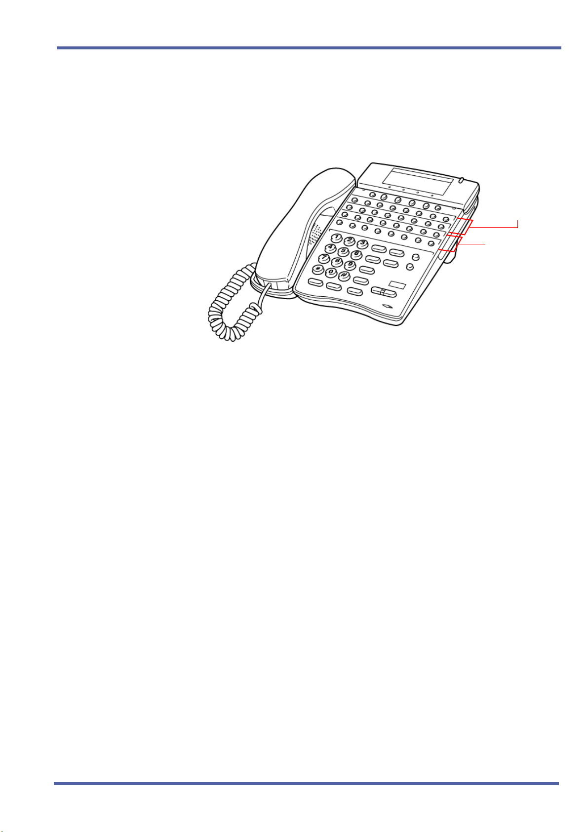
One-Touch Keys
One-Touch keys can perform the same function as Feature Access keys.
A Multiline Terminal has a fixed number of these keys. No system
assignment is necessary, and the number of keys ranges from none to 16
depending on the terminal type.
Line/Feature
Access Keys
One-Touch Keys
Figure 2-1: Key Assignment Example
DTU-type Multiline Terminals
The DTU-type multiline telephones are available in a variety of
colours, display and non-display types and line sizes.
Two colours are generally available: black and white.
Two display types: with LCD and without LCD. The large Liquid Crystal
Display (LCD) on the display terminals provides call status data and
programming information.
Three lines sizes: 8-line, 16-line and 32-line.
Speakerphones with full handsfree operation and headset jacks
are standard.
term
The D
(display only).
An Attendant Add-On DCU-60-1A(BK)/(WH) CONSOLE is available
for 60 station and/or outside line assignments and 12 function keys.
Series i Handset Cordless terminal is a 16-button phone
An SLT Adapter can be used in place of a digital terminal for
connecting Single Line Telephones, or similar devices.
Doc. No. 8201 - Release 1.0
July 2003
Features and Specifications Manual Chapter 2 – 7
Page 18

July 2003 NEC Business Solutions Ltd
THIS PAGE INTENTIONALLY LEFT BLANK
8 – Chapter 2 Introduction
Doc. No. 8201 - Release 1.0
July 2003
Page 19

Features Chapter 3
S
ECTION
GENERAL
I
NFORMATION
1
All features available with the Xen IPK system are listed alphabetically by
name and described in this document. The following information is
provided, when applicable, for each feature:
Feature Description — briefly describes the feature and, when applicable,
tells how the feature is used by the end-user.
System Availability — describes Multiline Terminals that can be used with
this feature and lists any additional equipment, such as adapters or ETUs,
that must be installed for this feature to operate.
Operating Procedures – When applicable, detailed procedures for using
the feature are provided.
Quick Access Code Reference – provides a table that lists any Access
Codes that are used with the operation of the feature. This table is
only included for those features that have associated Access Codes.
This table has three columns: Default, Access Code Name, and
Alphabetic Designation.
Default – indicates the default values for the Access Codes (i.e., the
values as they are set when the system is first installed). All Access
Codes can be changed in System Programming with the exception of
the System and Fixed codes.
Access Code Name – indicates the name associated with the Access
Code. At the end of each code name, in parenthesis, is the code type.
There are four types of Access Codes: System, Feature, Intercom,
and Fixed.
z System Codes are usually 1-digit codes that apply to the
operation of the system. These codes can be changed in System
Programming.
z Feature Codes are typically 3-digit codes and indicate Access
Codes that apply to the associated feature, these codes can be
changed in System Programming.
z Intercom Codes are 2-digit codes that apply to the
associated feature and indicate Access Codes that can be
changed in System Programming.
z Fixed Codes cannot be changed, they are set in the system.
Alphabetic Designation – helps you to easily remember the Access
Code. It is the alphabetic equivalent of the Access Code. These
designations are only available for Feature and Intercom codes.
Doc. No. 8201 - Release 1.0
July 2003
Features and Specifications Manual Chapter 3 – 9
Page 20

July 2003 NEC Business Solutions Ltd
Service Conditions – provides specific conditions that apply to the
operation of this feature.
Related Features Lists – lists any associated features.
S
ECTION
OPERATING
P
ROCEDURES
2
The operating procedures are the same for the D
and ETW-Type Multiline Terminals. The D
additional keys; MIC, Directory and Message. Minor differences in the keys
are listed below. These differences are important when performing the
operations listed in the remainder of this manual.
Table 3-2: Comparison of Keys for D
Multiline Terminals
Dterm Series i
Terminals
A
B
A ~ K
J
L
C
D
term
term
Series i and DTU-Type
Series i terminals have three
term
Series i and DTU-type
DTP or DTU
Terminals
T
Q
A ~ 0
J
L
S
R
S
ECTION
F
EATURES
3
E
F
G
H
UV
Directory
Message
I
Features that are available with the Xen IPK system are listed in the
remainder of this chapter in alphabetical order by feature name.
P
O
N
U
M
N/A
N/A
N/A
Doc. No. 8201 - Release 1.0
July 2003
10 – Chapter 3
Page 21

Account Code Entry A-1
FEATURE
DESCRIPTION
SYSTEM
AVAILABILITY
OPERATING
PROCEDURES
The Account Code Entry feature allows assignment of Account Codes up to
16 digits. Account Codes are incorporated in the call records generated by
the Station Message Detail Recording (SMDR) option and provide a
reference for billing.
Terminal Type
All terminals.
Required Components
MIFM-U( ) ETU
From a Multiline Terminal with an outside call in progress:
1. Press T.
2. Dial Access Code
3. Enter the Account Code using the dial pad while talking with the
outside party.
FF (fixed Access Code).
4. Press
From a Multiline Terminal with an outside call on hold:
1. While receiving internal dial tone, dial Account Code Entry Access
Code
2. Enter the Account Code using the dial pad.
3. Retrieve the held call.
4. While receiving internal dial tone, press the Feature Access or
One-Touch key programmed for Account Code Entry.
5. Enter the Account Code using the dial pad.
6. Retrieve the held call.
T.
________ (not assigned at default).
- OR -
Doc. No. 8201 - Release 1.0
July 2003
Features and Specifications Manual A1 – 11
Page 22

July 2003 NEC Business Solutions Ltd
From a Single Line Telephone with an outside call in progress:
1. Press the hookswitch, and receive a new internal dial tone; the outside
party is put on hold.
QUICK ACCESS
CODE
REFERENCE
SERVICE
CONDITIONS
2. Dial Account Code Entry Access Code
________ (not assigned at
default).
3. Enter the Account Code using the dial pad.
4. Provide a hookflash to return to the held call.
Default Access Code Name
66 Account Code Entry
Alphabetic
Designation
N/A
(Feature Access - Fixed)
Data Assignment
The Account Code Entry Access Code, used after a call has been put
on hold (no default is provided), can be changed in System
Programming.
The ability to enter an Account Code is determined by System
Programming.
Restrictions
No Account Code can be entered when a station is a member of a
conference supported by the system.
A hookflash results in a conference when a Single Line Telephone has
a call on hold and another call is in progress. In this case, an Account
Code cannot be entered.
An Account Code Entry does not print with SMDR unless the account
code is entered after the Call Start Time elapses.
General
SMDR Reports on incoming calls is dependent on System
Programming. When an Account Code is entered during an outgoing
call, a call report is generated regardless of system assignment.
Multiline Terminal users can enter an Account Code while talking with
the outside party (no tones are sent to the CO line and the outside
party is not put on hold).
If multiple Account Codes are entered during one call, the last entry is
output from SMDR.
Account Code length can be up to 16 digits.
Account Codes can be programmed to a Feature Access or
One-Touch key on any Multiline Terminal.
During Account Code Entry, Call Alert Notification is not provided.
SMDR card must be present and enclosed in system programming for
account codes to work.
12 – A1 Account Code Entry
Doc. No. 8201 - Release 1.0
July 2003
Page 23

Xen IPK Features and Specifications Manual
RELATED
FEATURES LIST
GUIDE TO
FEATURE
PROGRAMMING
Order
and
Shortcut
¶+BTS
¶+BTT
Class of Service (Station) Feature Selection 2
Station to Class of Service Feature Assignment
Feature
Number
A-2 Account Code - Forced/Unverified
A-3 Account Code - Forced/Verified
S-15 Station Message Detail Recording (SMDR)
System Data Name
Feature Name
1-8-07
Memory
Block
1-8-08 3-6
4-17
Function
Attendant
Page-Line
Key
1-8-08
Station
Page-Line
Key
¶+BA
¶+BS
¶+BS
¶+BS
¶+AS
¶+AS
¶+AS
¶+AS
¶+AS
¶+AS
¶+CSS
¶+BM
Access Code (1-, 2-, or 3-Digit) Assignment 1-1-46/47/48 041
Card Interface Slot Assignment 7-1
MIF (SMDR) Assignment 7-3-02
MIF (LCR) Assignment 7-3-01
Printer Connected Selection
Printer Line Feed Control Selection 1-5-14
SMDR Incoming/Outgoing Print Selection 1-5-26
SMDR Valid Call Time Assignment 1-5-25
SMDR Print Format 1-5-02
SMDR Telephone Print Selection 4-56
COM Port Baud Rate Setting Assignment 1-8-35
Start Time Selection 1-1-05
1-5-13
When the system is at default this Memory Block must be programmed for the feature to be used.
Doc. No. 8201 - Release 1.0
July 2003
Features and Specifications Manual A1 – 13
Page 24

July 2003 NEC Business Solutions Ltd
THIS PAGE INTENTIONALLY LEFT BLANK
14 – A1 Account Code Entry
Doc. No. 8201 - Release 1.0
July 2003
Page 25

Account Code Forced/Unverified
FEATURE
DESCRIPTION
SYSTEM
AVAILABILITY
The Forced/Unverified Account Code feature forces the user to dial an
access code and an Account Code before being able to select an outside
line, but the account code entered is not verified against a list of stored
numbers (as it is in the Forced/Verified Account Code feature). This in effect
means that any number (of a specified length) can be entered without being
restricted to a certain selection only. The Account Code entered is then
presented in the SMDR report at the end of the call for account keeping or
identification purposes.
Terminal Type
All Terminals
Required Components
MIFM-U( ) ETU
A-2
OPERATING
PROCEDURE
To enter a Forced/Unverified Account Code from any station:
1. Lift the handset and wait for internal dial tone.
2. Dial the Forced Account Access Code. A second dial tone is received.
3. Dial the Forced/Unverified Account Code. Wait for internal dial tone.
4. Dial the Trunk Access code and the outside number.
To use this feature with Scrolling Directories:
1. Press the
speed dialling.
2. Press the
listed in the directory.
Press a dial pad key (to select the first letter of the name or number of
the desired speed dial buffer) and dial
V (SYS. or STA softkey) to designate system or station
V (UP or DOWN softkey) to view the names/numbers
- OR -
J.
3. To dial the number press
Doc. No. 8201 - Release 1.0
July 2003
Features and Specifications Manual A2 – 15
4. Enter the Account Code.
P or lift the handset.
Page 26

July 2003 NEC Business Solutions Ltd
SERVICE
CONDITIONS
Data Assignment
Use Memory Block 1-8-08 [Class of Service (Station) Feature
Selection 2], Page 6 LK3 to Allow (LED On) or Deny (default: LED Off)
Forced Account Code Unverified.
Use Memory Blocks 1-1-46~48 [Access Code (1-, 2-, or 3-Digit)
Assignment] to assign the Forced Account Code Access (Function
No. 147).
Use Memory Block 1-8-27 (Forced Account Code Length Assignment)
to assign the number of digits for Account Codes system-wide. One to
13 digits can be assigned; default is 10 digits.
Use Memory Block 7-1 (Card Interface Slot Assignment) to specify the
necessary MIFM-U( ) ETU.
Restrictions
Existing Code restrictions, Automatic Carrier Routing (ACR) and Least
Cost Routing (LCR) assignments are applied after Forced Account
Codes are entered.
Emergency 000 (111 NZ) calls cannot be made unless a valid Forced
Account Code is entered.
A one-touch key must be programmed on these handsets allowing
emergency number access.
Verified and Unverified Forced Account Codes cannot be used in the
same Class of Service.
General
Only outgoing calls from Intercom require a Forced Account Code.
Direct access to trunks bypasses this feature, that is, by pressing a line
key, or dialling trunk access code.
The Forced Account Code without verification feature allows the user
to place an outgoing call without Account Code verification only the
length is verified.
Reorder tone is provided if an outgoing call is dialled without entering
the Forced Account Code access code and a valid Forced
Account Code.
Call Alert Notification is not provided during Account Code Entry.
PBR Timer values apply when using a Single Line Telephone to enter
a Forced/Unverified Account Code.
Verified and Unverified Forced Account Codes will be printed on the
SMDR report if both features are used.
An ’A’ is placed in front of the Forced/Unverified Account Codes on the
SMDR reports to distinguish them from other Account Code entries.
The Interdigit Timer (10sec) is applicable when a user inputs an
Account Code. Busy Tone is received if the timer expires.
16 – A2 Account Code - Forced/Unverified
Doc. No. 8201 - Release 1.0
July 2003
Page 27

Xen IPK Features and Specifications Manual
RELATED
FEATURES LIST
GUIDE TO
FEATURE
PROGRAMMING
Order
and
Shortcut
¶+BA
¶+BTS
Access Code (1-, 2-, or 3-Digit) Assignment
Class of Service (Attendant) Feature
Selection 1
Feature
Number
A-1 Account Code Entry
A-3 Account Code - Forced/Verified
S-15 Station Message Detail Recording (SMDR)
System Data Name
Feature Name
Memory
Block
1-1-46/47/48 146,147
1-8-07 2-8
Function
1-8-07
Attendant
Page-Line
Key
1-8-08
Station
Page-Line
Key
¶+BTS
¶+AC
¶+AC
¶+BTT
¶+AC
¶+AC
¶+BF
¶+BS
¶+BS
¶+BS
¶+AS
Class of Service (Station) Feature Selection 2
Code Restriction Class Assignment (Day Mode) 4-07
Code Restriction Class Assignment (Night Mode) 4-08
Station to Class of Service Feature Assignment
Code Restriction Class (Without Authorisation
Code) Day Mode Assignment
Code Restriction Class (Without Authorisation
Code) Night Mode Assignment
Forced Account Code Length Assignment 1-8-27
Card interface Slot Assignment 7-1
MIF (SMDR) Assignment 7-3-02
MIF (LCR) Assignment 7-3-01
Printer Connected Selection
1-8-08 5-1, 6-3
4-17
4-64
4-65
1-5-13
¶+ AS
¶+ AS
¶+ AS
Doc. No. 8201 - Release 1.0
July 2003
Features and Specifications Manual A2 – 17
Printer Line Feed Control Selection 1-5-14
SMDR Incoming/Outgoing Print selection 1-5-26
SMDR Valid Call Time Assignment 1-5-25
Page 28

July 2003 NEC Business Solutions Ltd
Order
and
Shortcut
¶+ AS
¶+AS
¶+CSS
¶+BM
When the system is at default this Memory Block must be programmed for the feature to be used.
SMDR Print Format 1-5-02
SMDR Telephone Print Selection 4-56
COM Port Baud Rate Setting Assignment 1-8-35
Start Time Selection 1-1-05
System Data Name
Memory
Block
Function
Attendant
Page-Line
1-8-07
Key
1-8-08
Station
Page-Line
Key
18 – A2 Account Code - Forced/Unverified
Doc. No. 8201 - Release 1.0
July 2003
Page 29

Account Code Forced/Verified
FEATURE
DESCRIPTION
SYSTEM
AVAILABILITY
OPERATING
PROCEDURE
The Account Code - Forced/Verified feature forces selected station users to
dial an Access Code and a verified Account Code before making an
outgoing call. The outgoing call is processed only after the Dialled Account
Code is verified. This feature allows a system administrator to control
unauthorised outgoing calls. The Forced/Verified Account Code is part of
the Station Message Detail Recording (SMDR) call record. The maximum
number of digits for an Account Code is 13.
Terminal Type
All Terminals.
Required Components
MIFM-U( ) ETU
To enter a Forced/Verified Account Code from any station:
A-3
1. Lift the handset; receive internal dial tone.
2. Dial the Forced Account Access Code _______. (not assigned at
default). A second dial tone is received.
3. Dial the Forced Account Code _______. Internal dial tone is received.
4. Dial the Trunk Access code and the outside number.
To program Forced/Verified Account Code from Attendant Position:
1. Lift the handset; receive internal dial tone.
2. Dial the Forced Account Access Code (not assigned at default). A
second dial tone is received.
3. Dial the Forced Account Number (
4. Dial the Forced Account Code (default: 4 digits). Confirmation tone is
received.
5. Press
displayed. (Repeat steps 4 ~ 5 until all desired Account Codes
are entered.)
N to enter the information. The next Account Number is
00A ~ E00).
Doc. No. 8201 - Release 1.0
July 2003
Features and Specifications Manual A3 – 19
6. Press
P to finish entering Account Codes.
Page 30

July 2003 NEC Business Solutions Ltd
To use this feature with Scrolling Directories:
1. Press the V (SYS. or STA softkey) to designate system or station
speed dialling.
SERVICE
CONDITIONS
2. Press the
listed in the directory.
Press a dial pad key (to select the first letter of the name or number of
the desired speed dial buffer) and dial
3. To dial the number press
4. Enter the Account Code.
Data Assignment
Use Memory Block 1-8-07 [Class of Service (Attendant) Feature
Selection 1] Page 2 LK8 to Allow (default LED On) or Deny (LED off)
Attendant Positions to program Forced Account Codes.
Use Memory Block 1-8-08 [Class of Service (Station) Feature
Selection 2] Page 5 LK1 to Allow (LED On) or Deny (default: LED Off)
Account Code Forced/Verified.
Use Memory Block 1-8-27 (Forced Account Code Length Assignment)
to assign the number of digits for Account Codes system-wide. One to
13 digits can be assigned; default is 4 digits.
V (UP or DOWN softkey) to view the names/numbers
- OR -
J.
P or lift the handset.
Use Memory Block 7-1 (Card Interface Slot Assignment) to specify the
necessary MIFM-U( ) ETU.
20 – A3 Account Code - Forced/Verified
Doc. No. 8201 - Release 1.0
July 2003
Page 31

Xen IPK Features and Specifications Manual
Error Displace
and T one
NO
NO
Account Code Access
Enter trunk Access Code
Check against 4-07, 4-08
Figure A3-1: Account Code Forced/Verified
Speaker or Off Hook
(ICM DT)
YES
Correct F/V
YES
Correct F/V
Account Code
YES
ICM (DT)
(Second DT)
Dial Digits
Dial destination if number allowed.
MB 1-1-46/47/48
MB 1-1-46/47/48
Press Off Line Key
(Network DT)
Dial Digits
Check against 4-07, 4-08
Trunk Access Code
(Trunk Group
Route Advance)
or CO/PBX
Dial Digits
Check Agent
4-64, 4-65
Restrictions
Existing restrictions and Least Cost Routing (LCR) assignments are
applied after Forced Account Codes are entered.
Emergency 000 (111 NZ) calls cannot be made unless a valid Forced
Account Code is entered. In such cases, provide access to emergency
numbers by programming them into One-Touch or Feature Access
keys.
Verified and Unverified Forced Account Codes cannot be used in the
same class of service.
General
Only outgoing calls from an intercom require a Forced Account Access
Code. Direct access to trunks bypasses this feature.
Reorder tone is provided if an outgoing call is Dialled without entering
the Forced Account Access Code and a valid Forced Account Code.
Call Alert Notification is not provided during Account Code Entry
verification and programming.
PBR Timer values apply when using a Single Line Telephone to enter
a Forced/Verified Account Code.
Forced Account Codes can be uploaded, downloaded, or modified
using PC based System Programming.
Forced Account Code and Account Code entries print on the SMDR
Doc. No. 8201 - Release 1.0
July 2003
Features and Specifications Manual A3 – 21
report if both are used.
Page 32

July 2003 NEC Business Solutions Ltd
A is placed in front of the Forced Account Codes on the SMDR reports
to distinguish them from other Account Code entries.
Attendant Positions can be used to program Forced Account Codes
only if allow is assigned in Attendant Class of Service.
The maximum number of Forced Account Codes that can be entered
system-wide is 500.
When the Interdigit time (default 10s) expires after the user inputs a
Forced Account Code, busy tone is generated.
RELATED
FEATURES LIST
Feature
Number
Feature Name
A-1 Account Code Entry
A-2 Account Code - Forced/Unverified
S-15 Station Message Detail Recording (SMDR)
22 – A3 Account Code - Forced/Verified
Doc. No. 8201 - Release 1.0
July 2003
Page 33

Add-On Conference A-4
FEATURE
DESCRIPTION
SYSTEM
AVAILABILITY
OPERATING
PROCEDURES
The Add-On Conference feature allows a conference call with a maximum
of four parties with various combinations of outside lines and stations. This
increases efficiency by allowing multiple parties to enter into a conversation.
Up to sixteen 4-party conferences are allowed with no more than two
outside lines per conference.
Terminal Type
All stations.
Required Components
None.
To initiate an Add-On Conference using a Multiline Terminal with a
call in progress:
1. Press R.
2. Dial a station number or outside party, and inform the answering party
of the conference.
Doc. No. 8201 - Release 1.0
July 2003
3. Press
4. Repeat steps 1~3 to add an additional party to the conference.
To initiate an Add-On Conference using a Single Line Telephone
with a call in progress:
1. Press the hookswitch to place the first call on hold.
2. Dial an internal station and announce conference.
3. Press the hookswitch again. Talk with both parties.
Ragain. TheRLED lights solid. Talk with both parties.
Note: Refer to Privacy Release, on Page 465 for a different method of
entering conference.
Features and Specifications Manual A4 – 23
Page 34

July 2003 NEC Business Solutions Ltd
SERVICE
CONDITIONS
Restrictions
A Single Line Telephone cannot be used to originate a 2-party CO
conference.
A Multiline Terminal user that is put on hold cannot enter into another
conference.
General
The elapsed time of the call (from the originating terminal) is shown on
all the Multiline Terminals with a display.
When all sixteen conference circuits are in use, the Conference key
lights solid red on all Multiline Terminals.
Allowed conference configurations are:
z 4 terminals - no outside party
z 3 terminals - 1 outside party
z 3 terminals - no outside party
z 2 terminals - 1 outside party
z 1 terminal - 2 outside parties
Only one member of a conference can place a conference on hold at
atime.
RELATED
FEATURES LIST
When the conference is placed on hold, the Conference LED flashes
on all phones in the conference.
No recall is provided at the Multiline Terminal when a conference is
on hold.
The CO to CO db loss of conference is 6 db (3 db per CO). This value
does not include the loss already occurring on each CO circuit. A
telephone for conference connection incurs a 10 db loss in volume.
Features which can use conference circuits are: Voice Over Split (V-2), Live
Recording (D-6), Barge-In (B-3), Unsupervised Conference (U-4) and Addon Conference.
Feature
Number
Feature Name
A-26 Automatic Release
P-8 Privacy Release
24 – A4 Add-On Conference
Doc. No. 8201 - Release 1.0
July 2003
Page 35

All Call Page A-5
FEATURE
DESCRIPTION
SYSTEM
AVAILABILITY
OPERATING
PROCEDURES
The All Call Page feature allows simultaneous paging (internal and
external) of all idle Multiline Terminals in a zone over their built-in speakers
and over all external paging speakers. This enables a person, away from
their desk but within hearing distance of a Multiline Terminal or external
speaker, to respond to the paging call.
Terminal Type
All Terminals.
Required Components
None.
To originate a page on a Multiline Terminal:
1. Lift the handset, and receive internal dial tone (or press U, if the
user is already engaged on a call).
2. Dial Access Code
3. Page.
EI (set as default) for All Call Page.
Doc. No. 8201 - Release 1.0
July 2003
To answer a page on a Multiline Terminal:
1. Go off-hook.
2. Receive internal dial tone.
3. Dial Meet-Me Access Code
changes to show the originator station number.
4. Talk with All Call Page originator.
EJ (set as default); the display
Features and Specifications Manual A5 – 25
Page 36

July 2003 NEC Business Solutions Ltd
To originate a page on a Single Line Telephone:
1. Lift the handset, and receive internal dial tone or press the hookswitch
if the user is already engaged in a call.
QUICK ACCESS
CODE
REFERENCE
2. Dial Access Code
EI (set as default) for All Call Page.
3. Page.
To answer a page on a Single Line Telephone:
1. Lift the handset or press the hookswitch if the user is already engaged
in a call.
2. Receive dial tone.
3. Dial Meet-Me Access Code
EJ (set as default).
4. Talk with All Call Page originator.
Default Access Code Name
Alphabetic
Designation
59 All Internal/External Zone Paging N/A
5* Internal/External Meet-Me N/A
SERVICE
CONDITIONS
Data Assignment
Stations can be allowed or denied receiving paging through System
Programming. This includes All Call Page, Internal Zone Paging, and
External Zone Paging. This does not include Internal Emergency All
Call Page.
In System Programming, paging alert tone (Internal and/or External)
can be allowed or denied system-wide. The default assignment is
Receive Paging Alert Tone.
Restrictions
Multiline Terminal users engaged in a handsfree call do not receive All
Call Page or Internal Zone Pages.
Multiline Terminals provided with Off-Hook Voice Announcement
cannot receive All Call Page when already engaged in a call.
Only one All Call Page or Internal Zone Page can be established at a
time. Another page can be originated as soon as the first is abandoned
or answered (by Meet-Me Answer).
Doc. No. 8201 - Release 1.0
July 2003
26 – A5 All Call Page
Page 37

Xen IPK Features and Specifications Manual
Simultaneous zone paging (Internal Zones A, B, and C) can be
established at one time; however, All Internal Zone Paging and
Internal Emergency All Call Page cannot be performed if any other
internal page is in use.
General
All Call Page can be originated or answered (by Meet-Me Answer)
from internal dial tone.
All Call Page times out using the External Paging Time Out with a
default time of five minutes.
An outside line can be conferenced with External Page to allow a
conversation to be monitored.
The default Access Code for All Call Page is 59. The default Access
Code for All Call Page Meet-Me code is 5
Meet Me).
* (Internal/External
RELATED
FEATURES LIST
GUIDE TO
FEATURE
PROGRAMMING
Order
and
Shortcut
¶+BA
¶+BTM
¶+BTT
Access Code (1-, 2-, or 3-Digit) Assignment 1-1-46/47/48
Internal Zone Paging Selection 4-93
Receiving Internal/All Call Page Selection 4-31
Feature
Number
E-1 Elapsed Call Timer
I-6 Internal Zone Paging (Meet Me)
System Data Name
Memory
Block
Feature Name
Function
070~079,
081
1-8-07
Attendant
Page-Line
Key
1-8-08
Station
Page-Line
Key
¶+BP
¶+BP
¶+BP
¶+BP
¶+BP
Doc. No. 8201 - Release 1.0
July 2003
Features and Specifications Manual A5 – 27
Internal Paging Alert Tone Selection 1-2-25
Internal Paging Timeout Selection 1-2-00
External Speaker Connection Selection 1-7-02
External Paging Alert Tone Selection 1-7-03
External Speaker Pre-Tone/Chime Selection 1-7-08
Page 38

July 2003 NEC Business Solutions Ltd
Order
and
Shortcut
¶+BP
¶+BP
System Data Name
External Speaker Chime Start time Selection 1-7-09
External Paging Timeout Selection 1-7-06
Memory
Block
Function
1-8-07
Attendant
Page-Line
Key
1-8-08
Station
Page-Line
Key
28 – A5 All Call Page
Doc. No. 8201 - Release 1.0
July 2003
Page 39

Alphanumeric Display A-6
FEATURE
DESCRIPTION
Each Display Multiline Terminal is equipped with a 24-character by 3-line
Liquid Crystal Display (LCD). These displays provide information such as:
date/time, elapsed call time on outside calls, digits Dialled, internal calling
party number, Customised Message, and Speed Dial entries.
SYSTEM
AVAILABILITY
Terminal Type
All Multiline Terminals with a Display.
Required Components
None.
LCD DISPLAYS
Display Location Definition
12:24 AM WED 10
FWD 100 - > [ ] Set Call Forward - All Calls
ALL FWD CANCLD Cancel DND/Call Forward - All Calls System-Wide
FWD/DND CANCLD
All Stations
with LCD
Originator
Clock/Calendar
Cancel DND/Call Forward - All Calls At Individual Stations
FWD SET [ ]
FWD RESET [ ] Reset Call Forward - All Calls From Forward To Extension
BUSY 100 -- > [ _ ] Set Call Forward - Busy
FWD BUSY CANCLD Cancel Call Forward - Busy
NOANS 100 - > [ ] Set Call Forward - No Answer
FWD NA CANCLD Cancel Call Forward - No Answer
FWD BNA - > [ ] Set Call Forward Busy - No Answer
FWD BNA CNCL Cancel Call Forward Busy - No Answer
BACK MM/DD HH:MM Set Customised Message
MESSAGE CLEAR Cancel Customised Message System-Wide or From Individual
NIGHT MODE SET Night Mode Switch
NIGHT MODE RESET Reset Night Mode
NT TENANT Set Night Mode For Tenant
CALLBACK CANCLD Cancel Callback System-Wide
Doc. No. 8201 - Release 1.0
July 2003
Originator
Set Call Forward - All Calls From Forward To Extension
Station
Features and Specifications Manual A6 – 29
Page 40

July 2003 NEC Business Solutions Ltd
Display Location Definition
FNC LAMP OFF Reset FNC LED
CURRENT PASSWORD ?
NEW PASSWORD ?
ENTER PASSWORD
RESTRICT SET
CALL DENIED
RESTRICT CANCLD
Originator
Originator
Originator
Originator
Originator
Originator
Telephone Password (1)
Telephone Password (2)
Set Password (CO/PBX Restriction)
After Setting Password
Display on Station Outgoing Restricted Telephone
After Cancelling Outgoing Call Restriction
CANCEL TEL Cancel Restriction on Another Telephone
RLY 0 ON Relay On
RLY 0 OFF Relay Off
ALARM AM 00 : 00 Set Alarm For A.M.
ALARM PM 00 : 00 Set Alarm For P.M.
ALL ALARM CANCLD Cancel Alarm System-Wide
SET TIME REMINDR Set Timed Alarm for SLT
DND SET
*<– – XXXXXXXXXX
ALL PAGE
Originator
Originator
Originator
Set Do Not Disturb
Save and Repeat Number Is Stored
Internal All Zone Paging
GROUP [ A ] Group Paging
SPKR [ A ]
Originator
External Speaker
TRF SET CO = Set Automatic Tandem Trunk Transfer IN/OUT Trunk
TRF CNCL CO = Reset Automatic Tandem Trunk Transfer
TRF TO CO = Set or Confirm Transferred Trunk of Automatic Tandem Trunk
Transfer
TRNS TO N / A Transferred Trunk Not Assigned
00 : EMPTY No Speed Dial Number Entered
00 : 0 1 2 3 4 5 6 7 8 9 Speed Dial Number Confirmation
NO SMDR Station Message Detail Recording Not Available
ERROR Error Message
BUSY Busy Message
PRINTER TROUBLE Printer Problems
SPKR [ A , B , C ]
LINE IDLE
TRUNK QUE SET
Originator
Originator
Originator
External All Paging
Trunk Queuing; CO/PBX Trunk Idle
Trunk Queuing Set
LNR [ # ] / SPD [ ] Press LNR/SPD Key
TRUNK QUE CANCLD
Originator
Trunk Queue cancelled
30 – A6 Alphanumeric Display
Doc. No. 8201 - Release 1.0
July 2003
Page 41

Xen IPK Features and Specifications Manual
Display Location Definition
RCL : 0 1 , 0 2 , 0 3 , 0 4
120 < - [ 1 1 0 ] TRANSF
120 = = [ 1 1 0 ] TRANSF Automatic Ring Transfer
OVD > [ ] Barge-In On CO/PBX Line (1)
OVD - > CO [ ] Barge-In On CO/PBX Line (2)
100 < - TIE LN — Tie Line Answer
100 < - DID LN — DID Answer
DATA ENTRY Enter Data Via System Programming
STA NUMBER? Call Pickup Direct Originate
100 _ _ [101]URGENT Voice Over Split Originate/Receive
01/12147517627 Caller ID Indication
MUSIC SET/RESET Background Music is On/Off
100 Extension number only to be displayed at idle
NAME Extension name only to be displayed at idle
10 NAME Extension No.2 digits with number and name display
100 NAME Extension No.3 digits with number and name display
Originator
Destination
Hold Recall
Ring Transfer
1000 NAME Extension No.4 digits with number and name display
SERVICE
CONDITIONS
French, Spanish and Japanese characters are also available for some
displayed test.
Doc. No. 8201 - Release 1.0
July 2003
Features and Specifications Manual A6 – 31
Page 42

July 2003 NEC Business Solutions Ltd
GUIDE TO
FEATURE
PROGRAMMING
Order
and
Shortcut
¶+BCT
¶+BTT
¶+BE
¶+BI
¶+BTM
When the system is at default this Memory Block must be programmed for the feature to be used.
Trunk Name/Number Assignment
Station Name Assignment
Speed Dial Number/Name Display Selection 1-1-33
Customised Message 1~10 Assignment 1-2-09~18
Multilingual LCD Indication Selection 4-28
System Data Name
Memory
Block
3-00
4-18
Function
Attendant
Page-Line
1-8-07
Key
1-8-08
Station
Page-Line
Key
32 – A6 Alphanumeric Display
Doc. No. 8201 - Release 1.0
July 2003
Page 43

Ancillary Device Connection
FEATURE
DESCRIPTION
SYSTEM
AVAILABILITY
The Ancillary Device Connection feature allows installation of selected
peripheral (ancillary) devices such as an amplified handset, headset,
Analogue telephone devices, or external speakerphone for use on any
Multiline Terminal. This feature enhances operation for which the peripheral
devices are designed.
term
A D
Unit (Analogue Port Adapter with Ringer) or AP(A)-R( ) Unit (Analogue Port
Adapter without Ringer) for analogue telephone devices, or installing the
AD(A)-R( ) Unit to connect devices such as tape recorders.
The AP(A)-R( )/AP(R)-R( ) Unit is the interface for installing a Single LIne
Telephone, Modem, Credit Card Reader, Wireless Headset, Conferences
unit or other compatible analogue devices.
Terminal Type
D
Series i Terminal user can accomplish this by using the AP(R)-R( )
term
Series i Multiline Terminals, except DTR-2DT-1A.
A-7
OPERATING
PROCEDURES
SERVICE
CONDITIONS
Required Components
AD(A)-R( ), AP(A)-R( ), AP(R)-R( )
Vary, depending on the ancillary device connected:
Data Assignment
Use Memory Block 1-1-02 (Hookflash Time Selection) to specify the
loop open time for a hookflash signal sent to the CO/PBX when the
recall key on a Multiline Terminal is pressed.
Use Memory Block 1-3-02 (SLT Hookflash Signal Selection) to specify
whether a line is held internally or, if behind a PBX, a hookflash (HF)
signal is sent to the line when a Single Line Telephone user performs a
hookflash.
Use Memory Block 4-24 (SLT Hookflash Assignment) to either hold or
disconnect the trunk for the Single Line Telephone (SLT) hooking
operation.
Use Memory Block 4-39 (APR Ring Mode Assignment) to assign the
AP(R)-R( ) Unit for NON (No Ring), STA (default: ring Station Number
only) or ALL.
Use Memory Block 4-59 (APR Hookflash Selection) to allow or deny
hookflash on an AP(R)-R( ) unit.
Doc. No. 8201 - Release 1.0
July 2003
Features and Specifications Manual A7 – 33
Page 44

July 2003 NEC Business Solutions Ltd
General
The optional devices fit underneath the appropriate terminal.
An AP(A)-R( ) or AP(R)-R( ) Unit with hookflash enabled follows the
same operating procedures as a Single Line Terminal connected to an
SLI( )-U( ) ETU.
GUIDE TO
FEATURE
PROGRAMMING
Order
and
Shortcut
¶+BTM
¶+AU
¶+BTI
¶+BTI
¶+BCM
¶+BTI
System Data Name
APR Ring Mode Assignment 4-39
APR/APA Hookflash Selection 4-59
DTMF/DP SLT Type Selection 4-95
SLT Hookflash Signal Selection 1-3-02
Hookflash Time Selection 1-1-02
SLT Hookflash Assignment 4-24
Memory
Block
Function
1-8-07
Attendant
Page-Line
Key
1-8-08
Station
Page-Line
Key
34 – A7 Ancillary Device Connection
Doc. No. 8201 - Release 1.0
July 2003
Page 45

Answer Hold A-8
FEATURE
DESCRIPTION
SYSTEM
AVAILABILITY
OPERATING
PROCEDURES
The Answer Hold feature enables a Multiline Terminal user to press the
flashing Answer key to answer an incoming ringing call on a CO line key. If
the Multiline Terminal user is already engaged in a call, the first call is
automatically placed on Non-Exclusive Hold when the second call is
answered. Answer Hold is particularly useful at Attendant Positions or other
central answering positions. Using the Answer key speeds call handling,
while Answer Hold prevents accidental call dropping.
Terminal Type
All Multiline Terminals.
Required Components
None.
To answer calls on a different line key with a call in progress:
1. Receive CO/PBX incoming ring. The O LED flashes.
2. Press
original call is put on Hold.
O, and answer the new call (O LED goes off). The
SERVICE
CONDITIONS
Doc. No. 8201 - Release 1.0
July 2003
a. If the original call was on a Call Appearance Key, the call is placed
on Non-Exclusive Hold on the Call Appearance Key.
b. If the call was on a line key, the call is placed on Non-Exclusive
Hold on the line key.
3. Talk with the CO/PBX incoming caller.
4. If additional calls are received, press
on Hold and connect to the next call. (Refer to a. and b. above.)
Restrictions
The Answer Hold feature does not function for incoming internal calls.
CO/PBX incoming calls not assigned to ring or assigned to other
tenants do not activate the Answer Hold feature.
DID/Tie line and DIT/ANA calls do not activate the Answer
Hold feature.
If all the Call Appearance keys are in use, the next call cannot
be answered.
O to place the current call
Features and Specifications Manual A8 – 35
Page 46

July 2003 NEC Business Solutions Ltd
General
CO/PBX ringing transfer/camp-on calls may be answered.
If multiple incoming calls activate the Answer key LED, the LED
continues to flash until all the calls are answered.
GUIDE TO
FEATURE
PROGRAMMING
Order
and
Shortcut
¶+BTT
¶+BTT
¶+BTM
¶+BTM
¶+BTM
¶+BTP
¶+BTP
¶+BTS
¶+BM
System Data Name
CO/PBX Ring Assignment (Day Mode)
CO/PBX Ring Assignment (Night Mode)
Line Key Selection for Telephone Mode 4-12
Extension Line Key Ring Assignment (Day Mode) 4-37
Extension Line Key Ring Assignment (Night
Mode)
Doorphone Chime Assignment (Day Mode) 4-03
Doorphone Chime Assignment (Night Mode) 4-04
Off-Hook Ringing Selection
Hold Recall Time Selection (Non-Exclusive Hold) 1-1-03
Memory
Block
4-01
4-02
4-38
4-51
Function
1-8-07
Attendant
Page-Line
Key
1-8-08
Station
Page-
Line Key
When the system is at default this Memory Block must be programmed for the feature to be used.
36 – A8 Answer Hold
Doc. No. 8201 - Release 1.0
July 2003
Page 47

Answer Key A-9
FEATURE
DESCRIPTION
SYSTEM
AVAILABILITY
OPERATING
PROCEDURES
Multiline Terminals are equipped with an Answer key and associated LED.
The Answer key LED flashes when the Multiline Terminal user receives an
incoming CO/PBX, Tie/DID transferred, and CO/PBX transferred call
ringing/or not ringing in the same tenant group. When multiple calls are
received, the Answer key is used to pick up calls. The Answer key
continues flashing until the last unanswered call is answered. Press the
Answer key during a call to hold the current call and allow the next call to be
answered.
Terminal Type
All Multiline Terminals.
Required Components
None.
To answer calls using the Answer key:
1. Receive CO/PBX incoming ring or flashing MW lamp without ringing.
O LED flashes.
SERVICE
CONDITIONS
Doc. No. 8201 - Release 1.0
July 2003
2. Press
3. Talk with the CO/PBX incoming calling party.
4. If additional CO incoming calls are received, the
again. Press
and connect the Multiline Terminal user to the next call.
a. If the original call was on a Call Appearance Key, the call is placed
b. If the call was on a line key, the call is placed on Non-Exclusive
Restrictions
Internal calls, internal transfer/camp-on calls, Secondary Incoming
Extension, Automated Attendant, and Tie/DID calls do not activate the
Answer key LED.
O. The O LED goes out.
O LED flashes
O to place the current call on Non-Exclusive Hold
on Non-Exclusive Hold on the Call Appearance Key.
Hold on the line key.
Features and Specifications Manual A9 – 37
Page 48

July 2003 NEC Business Solutions Ltd
General
The Answer key LED functions for incoming CO/PBX calls, CO/PBX
transfer/camp-on calls, and transferred/camped-on Tie/DID calls.
Incoming CO/PBX ringing calls to other tenants, with the CO/PBX line
appearance and with or without ring assignment, activate the Answer
key LED.
Incoming calls answered by the Answer key are handled on a first in-
first out basis.
GUIDE TO
FEATURE
PROGRAMMING
Order
and
Shortcut
¶+BTT
¶+BTT
¶+BTM
¶+BTM
¶+BTM
¶+BTP
¶+BTP
¶+BCT
¶+BCT
System Data Name
CO/PBX Ring Assignment (Day Mode)
CO/PBX Ring Assignment (Night Mode)
Line Key Selection for Telephone Mode 4-12
Extension Line Key Ring Assignment (Day Mode) 4-37
Extension Line Key Ring Assignment (Night
Mode)
Doorphone Chime Assignment (Day Mode) 4-03
Doorphone Chime Assignment (Night Mode) 4-04
DIT Assignment 3-42
ANA Assignment 3-43
Memory
Block
4-01
4-02
4-38
Function
1-8-07
Attendant
Page-Line
Key
1-8-08
Station
Page-Line
Key
¶+BTS
¶+BTT
¶+BTT
When the system is at default this Memory Block must be programmed for the feature to be used.
38 – A9 Answer Key
Off-Hook Ringing Selection
CO/PBX Answer Key Operation Without Ringing
Assignment (Day Mode)
CO/PBX Answer Key Operation Without Ringing
Assignment (Night Mode)
4-51
4-52
4-53
Doc. No. 8201 - Release 1.0
July 2003
Page 49

Assigned Night Answer (ANA)
FEATURE
DESCRIPTION
SYSTEM
AVAILABILITY
OPERATING
PROCEDURES
A-10
The Assigned Night Answer (ANA) feature is a Direct Inward Termination
programmed to ring directly at a selected station when the system or tenant
is in the Night Mode. This assignment operates independently from the DIT
(Day Mode) ringing assignment.
Terminal Type
All terminals.
Required Components
None.
Normal incoming call handling procedures apply.
SERVICE
CONDITIONS
Data Assignment
CO/PBX lines can be assigned to ring a station number, a hunt group
master number, or an ACD/UCD Pilot number.
Multiple CO/PBX lines can be assigned to ring at the same station,
hunt group master number, or ACD/UCD Pilot number.
Incoming ANA calls follow the station Call Forward setting.
Restrictions
When a CO/PBX line is assigned for ANA, the Night Mode CO/PBX
ring assignment is disabled.
General
ANA incoming ringing is assigned for Distinctive Ring or Synchronous
Ring system-wide.
When a busy station, programmed for ANA, receives an incoming
ANA call, the system provides Camp-On tone for the busy station. The
calling party receives ringback tone until the call is answered.
A Call Pickup for the same tenant, Access Code 68 (set at default),
can be used to answer ANA calls.
ANA calls do not activate External Tone Ringer or Night Chime.
Doc. No. 8201 - Release 1.0
July 2003
Features and Specifications Manual A10 – 39
Page 50

July 2003 NEC Business Solutions Ltd
ANA calls can be assigned to ring on voice mail ports. A hunt group
can be assigned by using the internal master hunt number
assignments.
When a station, programmed for ANA, receives an incoming ANA call,
internal ring tone is heard at all stations where a secondary incoming
extension appeACR and is assigned to ring.
Incoming ANA calls cannot be answered directly at the CO line key
appearance. The CO line key indicates Other Use (red LED).
While receiving an incoming ANA call, an internal call cannot be made.
ANA or DIT ringing can be delayed for 0, 5, 10, 20, 30, 40, 50,
60 seconds.
RELATED
FEATURES LIST
GUIDE TO
FEATURE
PROGRAMMING
Order
and
Shortcut
¶+BCT
¶+BCT
¶+BCT
¶+BCT
DIT Assignment 3-42
ANA Assignment
DIT/ANA Delay Answer Time Selection 3-61
DIT Tenant Assignment 3-62
Feature
Number
D-10 Direct Inward Termination (DIT)
System Data Name
Memory
Block
3-43
Feature Name
Function
1-8-07
Attendant
Page-Line
Key
1-8-08
Station
Page-Line
Key
¶+BCT
¶+BCT
¶+BN
¶+BTT
¶+BN
¶+BTM
40 – A10 Assigned Night Answer (ANA)
DIT Weekend Mode Selection 3-63
DIT Night Mode Delay Answer Selection 3-64
Trunk to Tenant Assignment 2-01
Telephone to Tenant Assignment 4-09
Line Key Selection for Tenant Mode 2-06
Line Key Selection for Telephone Mode 4-12
Doc. No. 8201 - Release 1.0
July 2003
Page 51

Xen IPK Features and Specifications Manual
Order
and
Shortcut
¶+BTT
¶+BM
When the system is at default this Memory Block must be programmed for the feature to be used.
Call Forward - Busy Immediately/Delay Selection 4-42
Call Forward - No Answer Time Selection 1-2-22
System Data Name
Memory
Block
Function
Attendant
Page-Line
1-8-07
Key
1-8-08
Station
Page-Line
Key
Doc. No. 8201 - Release 1.0
July 2003
Features and Specifications Manual A10 – 41
Page 52

July 2003 NEC Business Solutions Ltd
THIS PAGE INTENTIONALLY LEFT BLANK
42 – A10 Assigned Night Answer (ANA)
Doc. No. 8201 - Release 1.0
July 2003
Page 53

Attendant Add-On Console A-11
FEATURE
DESCRIPTION
SYSTEM
AVAILABILITY
OPERATING
PROCEDURES
The Attendant Add-On Console functions in conjunction with a Multiline
Terminal programmed as an Attendant. This console provides access to a
maximum of 48 stations and/or outside lines. The Busy Lamp Field status is
shown as a red LED for each station or trunk. Trunks can include CO/PBX,
ISDN, DID and E&M Tie Lines. In addition, the Attendant Add-On Console
also has 12 function keys that can be used for attendant messaging, paging
access, or other undefined functions.
Terminal Type
Any terminal programmed as an Attendant Position.
Required Components
DCR-60-1A( ) or DCU-60-1A( ) Console.
To transfer a call:
1. Attendant answers an incoming CO/PBX call.
2. Press the DSS/BLF key for the desired station. The calling party is put
on Non-Exclusive Hold.
Doc. No. 8201 - Release 1.0
July 2003
3. When the called party answers the Attendant call, the Attendant
announces the call and then presses
Console.
4. Go on-hook.
- OR -
Attendant answers an incoming CO/PBX call.
5. Press the Attendant Add-On Console key for the desired station. The
calling party is put on Non-Exclusive Hold.
6. Press
7. Go on-hook.
N on the Add-On Console.
N on the Attendant Add-On
Features and Specifications Manual A11 – 43
Page 54

July 2003 NEC Business Solutions Ltd
To call a station:
1. Lift the handset and receive internal dial tone.
2. Press the DSS/BLF key for the desired station. Hear ringback tone or
voice announce the station.
3. Called party answers.
To set/cancel Message Waiting or Station Outgoing Lockout
(Outgoing Restrict) to station:
1. Press the Message Wait or Station Lockout key.
2. Press the DSS/BLF key for the desired station.
SERVICE
CONDITIONS
To make an outgoing call using the Attendant Add-On Console from
the Attendant Position:
1. Go off-hook with the handset or just press a CO line key on the
Attendant Add-On Console.
2. Dial the desired number.
To answer an incoming call using the Attendant Add-On Console
from the Attendant Position
Press the incoming CO line key or flashing
Data Assignment
Additional attendant-type features can be allowed or denied in the
Class of Service (Attendant) Feature Selection.
Restrictions
A maximum of four DCR-60-1A( ) or DCU-60-1A( ) Consoles can be
installed per system.
O if ringing is assigned.
A maximum of four Attendant Add-On Consoles can be connected to
one station.
General
The 48 DSS keys and 12 function keys on Attendant Add-On Consoles
are flexible and can be changed.
Both DSS/BLF for stations and CO lines can appear on the same
DCR-60-1A( ) or DCU-60-1A( ) Consoles.
44 – A11 Attendant Add-On Console
Doc. No. 8201 - Release 1.0
July 2003
Page 55

Xen IPK Features and Specifications Manual
Depending on System Programming (DSS Call Voice/Tone Signal
Selection), the called party rings or receives a voice announcement
when an Attendant makes a call using the Attendant Add-On Console.
When the Attendant transfers a call, the transferred outside line
remains on Non-Exclusive Hold until the call is answered.
Each installed Attendant Add-On Console reduces the maximum
number of stations by one.
The keys are assigned at default as follows:
Keys
ICM Call Stations 100-147 (depending on
01~48
system configuration)
49
50~53
54
55
56~59
60
Night Mode
Direct Paging Access Internal Zone and All Zone Page
Vacant
Message
External All Zone Paging External Zone and All Zone Page
Transfer
Busy Lamp Field indications show if Multiline Terminals, outside lines,
or zone paging is in use.
Busy Lamp Field status indications at the Attendant Add-On
Console are:
LED Indications Busy Lamp Field Status
Off Station Idle
Green Not Used
Red Busy
Flashing DND, Call Forward - All Calls, Break Mode (by ACD
Agent)
Winking Function Programming Mode
LED Indications Outside Line Status
Off Outside Line Idle
Green In Use (by Attendant station)
Red Busy
Winking Call On Hold
Flashing Incoming Call
Doc. No. 8201 - Release 1.0
July 2003
Features and Specifications Manual A11 – 45
Page 56

July 2003 NEC Business Solutions Ltd
Message Waiting/Station Outgoing Lockout status indications at the
Attendant Add-On Console are:
LED Indications Station Status
Off No Message/Lockout Not Set
Green Message Waiting/Lockout Set
The Attendant, with an Attendant Add-On Console, can set a message
to a Single Line Telephone if the Single Line Telephone is equipped
with a Message Waiting LED and connected to a SLI(8)-U( ) ETU.
When the Message Waiting indication is set, the Large LED flashes
green on Multiline Terminals and continues to flash until the message
is cancelled by an Attendant.
Attendant Add-On Consoles can be assigned to any Multiline Terminal
programmed as an Attendant Position.
RELATED
FEATURES LIST
When the entire system is switched into the Night Mode, the Night
Transfer (NT) key LED on the Attendant Add-On Console lights red.
An Attendant Add-On Console cannot have a Message Wait key and a
Station Lockout key assigned at the same time.
If multiple CO calls are ringing at an Attendant Station or Attendant
Add-On Console, the calls are answered in first in-first out order.
Feature
Number
Feature Name
A-13 Attendant Positions
A-14 Attendant Station Outgoing Lockout
B-2 Background Music Over External Speakers
M-1 Message Waiting
46 – A11 Attendant Add-On Console
Doc. No. 8201 - Release 1.0
July 2003
Page 57

Xen IPK Features and Specifications Manual
GUIDE TO
FEATURE
PROGRAMMING
Order
and
Shortcut
¶+BS
¶+BTD
¶+BTD
¶+BTD
¶+BTS
¶+BTS
¶+BTT
¶+BTT
¶+BTT
1-8-07
System Data Name
Telephone Type Assignment
Attendant Add-On Console to Telephone Port
Assignment
Attendant Add-On Console Key Selection 1-6-05
DSS Call Voice/Tone Signal Selection 1-6-03
Class of Service (Attendant) Feature Selection 1 1-8-07 All
Class of Service (Station) Feature Selection 2 1-8-08 4-2
Station To Class Of Service Feature Assignment 4-17
CO/PBX Ring Assignment (Day Mode) 4-01
CO/PBX Ring Assignment (Night Mode) 4-02
Memory
Block
7-2
1-6-01
Function
Attendant
Page-Line
Key
1-8-08
Station
Page-Line
Key
¶+BTM
¶+BTM
¶+BTM
¶+BTT
¶+BTD
When the system is at default this Memory Block must be programmed for the feature to be used.
Line Key Selection for Telephone Mode 4-12
Extension Line Key Ring Assignment (Day Mode) 4-37
Extension Line Key Ring Assignment (Night Mode) 4-38
Prime Line/Hot Line Assignment 4-23
Attendant Transfer Selection During Live Record 1-6-08
Doc. No. 8201 - Release 1.0
July 2003
Features and Specifications Manual A11 – 47
Page 58

July 2003 NEC Business Solutions Ltd
THIS PAGE INTENTIONALLY LEFT BLANK
48 – A11 Attendant Add-On Console
Doc. No. 8201 - Release 1.0
July 2003
Page 59

Attendant Camp-On A-12
FEATURE
DESCRIPTION
SYSTEM
AVAILABILITY
OPERATING
PROCEDURES
The Attendant Camp-On feature, used at an Attendant Position with an
Attendant Add-On Console, allows a call to be transferred to a busy station.
Press the Transfer key on the Attendant Add-On Console to send the
Camp-On tone to the busy station. A camped on call that is not answered in
a preprogrammed time recalls to the Attendant Position.
Terminal Type
Any terminal with Display programmed as an Attendant Position.
Required Components
DCR-60-1A( ) or DCU-60-1A( ) Console.
To use this feature at an Attendant Position with a CO/PBX Call in
progress:
1. Press the DSS/BLF key on the Attendant Add-On Console or the
Attendant Position for the desired station.
2. Receive call waiting tone.
Doc. No. 8201 - Release 1.0
July 2003
3. Press
Position. Camp-On is set.
4. Go on hook.
5. After time-out, if the Camp-On is not answered, a recall tone is
received at the Attendant Position, and the LED on the assigned CO/
PBX line key or Call Appearance Key returns to flashing green.
6. Press the CO/PBX line key with the flashing green LED to return to
the call.
To answer a Camp-On Call from a Multiline Terminal:
1. The user is engaged in a call.
2. Receive a camp-on tone. The
flashes green, and CO/PBX line flashes green, if assigned.
3. Press
call is put on hold.
N on the Attendant Add-On Console or on the Attendant
O flashes red, the Large LED
O and talk with the CO/PBX incoming caller. The previous
Features and Specifications Manual A12 – 49
Page 60

July 2003 NEC Business Solutions Ltd
To answer a Camp-On Call from a Single Line Telephone:
1. The user is engaged in a call.
2. Receive a camp-on tone.
3. Hang up or put the call on System Call Park.
4. Go off-hook, and talk with the CO/PBX incoming caller.
SERVICE
CONDITIONS
Data Assignment
This feature is allowed only if the system is programmed for Ring
Transfer.
The Attendant Camp-On Recall Timer can be set for 30 seconds, 1,
1.5, 2, 3, 5, 8, or 10 minutes (default:1 minute).
In Class of Service (station) assignments, stations can be assigned not
to receive an Attendant Camp-On tone.
Restrictions
Camp-On is not allowed to stations that have received Tone Override.
General
The camp-on tone is heard over the handset or from the speaker if the
Multiline Terminal is in the handsfree mode.
Any number of outside calls can be camped on to a station. When the
station goes idle, the Camp-On calls are answered in order from the
lowest numbered lines to the highest numbered lines.
Two types of Camp-On are provided by the system
z Attendant Camp-On
z Station Camp-On.
RELATED
FEATURES LIST
Feature
Number
Feature Name
C-17 Class of Service
D-14 Do Not Disturb (DND)
S-12 Speed Dial – System
50 – A12 Attendant Camp-On
Doc. No. 8201 - Release 1.0
July 2003
Page 61

Xen IPK Features and Specifications Manual
GUIDE TO
FEATURE
PROGRAMMING
Order
and
Shortcut
¶+BTS
¶+BTS
¶+BTT
¶+BTT
¶+BM
1-8-07
System Data Name
System Transfer/Camp-On Selection 1-1-11
Class of Service (Station) Feature Selection 2 1-8-08 4-2, 3-3
Station To Class Of Service Feature Assignment 4-17
SLT Data Line Security Assignment 4-90
Attendant Add-On Console Transfer/Camp-On
Recall Time Selection
Memory
Block
1-1-64
Function
Attendant
Page-Line
Key
1-8-08
Station
Page-Line
Key
Doc. No. 8201 - Release 1.0
July 2003
Features and Specifications Manual A12 – 51
Page 62

July 2003 NEC Business Solutions Ltd
THIS PAGE INTENTIONALLY LEFT BLANK
52 – A12 Attendant Camp-On
Doc. No. 8201 - Release 1.0
July 2003
Page 63

Attendant Positions A-13
FEATURE
DESCRIPTION
SYSTEM
AVAILABILITY
OPERATING
PROCEDURES
SERVICE
CONDITIONS
Any number of stations can be designated an Attendant Position. These
stations have access to distinct Attendant-type features; up to four
attendants can support Attendant Add-On Consoles. Attendant features
such as setting Night Mode and System Speed Dial memory
programming apply.
Terminal Type
Any terminal with Display programmed as an Attendant Position.
Required Components
None.
Provided under specific Attendant feature descriptions:
Data Assignment
The first two station ports, 01 and 02, are assigned as Attendant
Positions by Resident System Programming.
Attendant features can be assigned to any station via station Class
of Service.
Doc. No. 8201 - Release 1.0
July 2003
Restrictions
A maximum of four Attendant Add-On Consoles can be assigned to
one Attendant Position.
A maximum of four Attendant Add-On Consoles can be assigned in
the system.
Up to four Attendant positions can have an Attendant Add-on Console.
Features and Specifications Manual A13 – 53
Page 64

July 2003 NEC Business Solutions Ltd
RELATED
FEATURES LIST
GUIDE TO
RELATED
PROGRAMMING
Order
and
Shortcut
Feature
Number
A-18 Automated Attendant
C-1 Call Alert Notification
C-7 Caller ID - Outgoing
D-14 Do Not Disturb (DND)
N-4 Night TransferNight Transfer
S-8 SLT Timed Alarm
S-12 Speed Dial – System
S-18 Station Relocation
System Data Name
Memory
Block
Feature Name
Function
1-8-07
Attendant
Page-Line
Key
1-8-08
Station
Page-Line
Key
¶+BS
¶+BTD
¶+BTD
¶+BTS
¶+BTS
¶+BTT
Telephone Type Assignment 7-2
Attendant Add-On Console to Telephone Port
Assignment
Attendant Add-On Console Key Selection 1-6-05
Class of Service (Attendant) Feature Selection 1 1-8-07
Class of Service (Station) Feature Selection 2 1-8-08 2-6, 4-2
Station to Class Of Service Feature Assignment 4-17
1-6-01
1-1~1-3,
1-7
54 – A13 Attendant Positions
Doc. No. 8201 - Release 1.0
July 2003
Page 65

Attendant Station Outgoing Lockout
FEATURE
DESCRIPTION
SYSTEM
AVAILABILITY
OPERATING
PROCEDURES
The Attendant Station Outgoing Lockout feature allows an Attendant
Position with an Attendant Add-On Console to set a predetermined Code
Restriction Class Assignment to any station that is assigned on the
Attendant Add-On Console. This allows an Attendant to set/reset
restrictions to disallow outgoing calls.
Terminal Type
Any Display terminal programmed as an Attendant Position.
Required Components
DCR-60-1A( ) or DCU-60-1A( ) Console.
To set the Attendant Station Outgoing Lockout from the Attendant
Position using the Attendant Add-On Console:
A-14
1. Press the key programmed as Lockout key on the Attendant AddOn Console.
2. Press the DSS key on the Attendant Add-On Console that is
associated with the station where Attendant Station Outgoing Lockout
is desired.
3. The green LED lights next to the DSS key to indicate lockout is set.
To cancel the Attendant Station Outgoing Lockout from the
Attendant Position using the Attendant Add-On Console:
1. Press the key programmed as Lockout key on the Attendant AddOn Console.
2. Press the DSS key on the Attendant Add-On Console that is
associated with the station where Attendant Station Outgoing Lockout
is to be cancelled.
3. The green LED next to the DSS key turns off to indicate the lockout
is cancelled.
Doc. No. 8201 - Release 1.0
July 2003
Features and Specifications Manual A14 – 55
Page 66

July 2003 NEC Business Solutions Ltd
SERVICE
CONDITIONS
Data Assignment
At default, when a station with Attendant Station Outgoing Lockout is
set, the station is outgoing restricted. This can be changed
(system-wide) to a different Code Restriction Class in
System Programming.
When up to four Attendant Add-On Consoles are installed, the
Attendant Station Outgoing Lockout is displayed only on the Attendant
Add-On Console from where the Lockout was set.
Restrictions
An Attendant Add-On Console, with an Attendant Station Outgoing
Lockout key assigned on it, cannot be used to set the Message
Waiting feature from an Attendant.
General
All Attendant Add-On Consoles can be used to set Attendant Station
Outgoing Lockout.
Attendant Station Outgoing Lockout is retained by the memory
backup battery.
No indication is provided at a terminal when Attendant Station
Outgoing Lockout is set.
RELATED
FEATURES LIST
To confirm that Attendant Station Outgoing Lockout is set at an
Attendant Add-On Console, ensure that the green LED associated
with the station is lit. Lockout remains set until cancelled at the
Attendant Add-On Console where it was set.
The station with Attendant Station Outgoing Lockout set cannot
manually cancel the lockout.
Feature
Number
Feature Name
M-1 Message Waiting
S-17 Station Outgoing Lockout
56 – A14 Attendant Station Outgoing Lockout
Doc. No. 8201 - Release 1.0
July 2003
Page 67

Xen IPK Features and Specifications Manual
GUIDE TO
FEATURE
PROGRAMMING
Order
and
Shortcut
¶+BTD
¶+AC
¶+AC
¶+AC
When the system is at default this Memory Block must be programmed for the feature to be used.
Attendant Add-On Console Key Selection
Code Restriction Class Assignment When
Lockout is Set
Code Restriction Class Assignment (Day Mode) 4-07
Code Restriction Class Assignment (Night Mode) 4-08
System Data Name
Memory
Block
1-6-05
1-1-70
Function
Attendant
Page-Line
1-8-07
Key
1-8-08
Station
Page-Line
Key
Doc. No. 8201 - Release 1.0
July 2003
Features and Specifications Manual A14 – 57
Page 68

July 2003 NEC Business Solutions Ltd
THIS PAGE INTENTIONALLY LEFT BLANK
58 – A14 Attendant Station Outgoing Lockout
Doc. No. 8201 - Release 1.0
July 2003
Page 69

Attendant Transfer A-15
FEATURE
DESCRIPTION
SYSTEM
AVAILABILITY
OPERATING
PROCEDURES
The Attendant Transfer feature permits efficient call transfers in the system
using an Attendant Multiline Terminal equipped with one to four Attendant
Add-On Console(s). Transferred calls can be voice announced, ring
transferred, or camped on (if the station is busy). All unanswered
transferred calls return to the Attendant with distinct audible and visual
indications, after a programmed time interval.
Terminal Type
Any terminal with Display programmed as an Attendant Position.
Required Components
DCR-60-1A Console or DCU-60-1A Console.
To use this feature at the Attendant Position with a CO/PBX call in
progress:
1. Press the DSS key on the Attendant Add-On Console or the Attendant
Position for the desired station.
SERVICE
CONDITIONS
2. Receive ringback tone or voice announcement.
3. Press
Position. The call is transferred.
4. Hang up.
5. After time-out, if the transferred call is not answered, a recall tone is
received at the Attendant Position; and the LED on the assigned CO/
PBX line key or Call Appearance Key returns to flashing green.
6. Press the CO/PBX line key with the flashing green LED to return to
the call.
Data Assignment
The Attendant Transfer/Camp-On recall time-out is programmable
(default: 60 seconds).
CO Transfer Ring Pattern and Ring Tone can be assigned in System
Programming.
N on the Attendant Add-On Console or on the Attendant
Doc. No. 8201 - Release 1.0
July 2003
Features and Specifications Manual A15 – 59
Page 70

July 2003 NEC Business Solutions Ltd
General
When a Transfer/Camp-On is denied, the call remains on hold at the
Attendant Position Multiline Terminal.
The outside line key LED flashes green on the station receiving the
Transfer/Camp-On, if the line appears on that station. The Large LED
also flashes green and the LED or the ANS key flashes red.
An Attendant trying to Transfer/Camp-On a call to a station may be
denied, if the Multiline Terminal is busy and receiving Tone Override.
RELATED
FEATURES LIST
GUIDE TO
FEATURE
PROGRAMMING
Order
and
Shortcut
¶+BTS
¶+BCS
System Transfer/Camp-On Selection
CO Transfer Ring Pattern Selection 1-1-13
Feature
Number
A-11 Attendant Add-On Console
A-12 Attendant Camp-On
A-26 Automatic Release
System Data Name
Memory
Block
1-1-11
Feature Name
Function
1-8-07
Attendant
Page-Line
Key
1-8-08
Station
Page-Line
Key
¶+BCS
¶+AU
¶+BTD
¶+BM
¶+AU
¶+BTT
When the system is at default this Memory Block must be programmed for the feature to be used.
60 – A15 Attendant Transfer
CO Transfer Ring Tone Selection 1-1-14
Class of Service (Station) Feature Selection 2 1-8-08 4-2
Attendant Add-On Console Key Selection 1-6-05
Attendant Add-On Console Transfer/Camp-On
Recall Time Selection
Automated Attendant Delay Announcement Hold
Tone Selection
MOH or Ring Back Tone Selection 4-66
1-1-64
1-4-17
Doc. No. 8201 - Release 1.0
July 2003
Page 71

Authorisation Code A-16
FEATURE
DESCRIPTION
SYSTEM
AVAILABILITY
OPERATING
PROECEDURES
Authorisation Code permits a station to dial outside numbers that would
otherwise be restricted. When an access code plus Authorisation Code is
dialled, the station code restriction class temporarily changes to allow calls
when permitted by a new code restriction class.
The Authorisation Code can be verified or unverified based on class of
service and is assigned in the Forced/Verified Account Code table (these
share the same table).
The Authorisation/Account Code is part of the Station Message Detail
Recording (SMDR) call record.
Terminal Type
All stations.
Required Components
None.
To enter Forced Account Code/Authorisation Code from any Station:
Doc. No. 8201 - Release 1.0
July 2003
1. Lift the handset or press P.
2. Dial Forced Account Code/Authorisation Code Access Code _______
(not set at default).
3. Dial the Account Code.
4. Dial the trunk access code and the outside number.
To program Forced Account Code/Authorisation Code from
Attendant position:
1. Lift the Handset or press
2. Dial Forced Account Code/Authorisation Code Programming Access
Code _______ (not set at default).
3. Dial the Forced Account Code/Authorisation Code Number
(001~500).
4. Dial the Account Code (default: 10 digits).
P.
Features and Specifications Manual A16 – 61
Page 72

July 2003 NEC Business Solutions Ltd
5. Press N to enter the information. The next Account Number
is displayed. Repeat steps 4~5 until all desired Account Codes
are entered.
SERVICE
CONDITIONS
6. Press
Codes.
Verified or Unverified for the Forced Account Code/Authorisation Code
features.
Memory Block 1-8-08 (Class of Service (Station) Feature Selection 2),
Page 6, LK 3 is used to activate assign Verified or Unverified for the
Forced Account Code/Authorisation Code features.
When a call is made without using an authorisation code, memory
blocks 4-64 and 4-65 are used to assign the code restriction class.
When a call is made using an authorisation code, the code restriction
class is temporarily changed and Memory Blocks 4-07 and 4-08 are
used to assign the code restriction class.
After placing a call using an authorisation code, if the Recall or Drop
keys are used, the temporary code restriction class remains with the
setting assigned in Memory Blocks 4-07 and 4-08 allowing the user to
dial another non-restricted number.
After placing a call using an authorisation code, when the station goes
idle (On-hook), the code restriction class is reset to its previous setting
assigned in Memory Blocks 4-64 and 4-65.
A total of 500 Forced Account Codes/Authorisation Codes can be
entered system-wide.
Forced Account Codes/Authorisation Codes and Account Code entries
Codes are printed on the SMDR report, if both are used.
P to stop entering Forced Account Codes/Authorisation
A is placed in front of the Forced Account Codes/Authorisation
Codes on the SMDR reports to distinguish them from other Account
Code entries.
When the Interdigit time (default is 10 seconds) expires during the user
input of a Forced Account Codes/Authorisation Code, Busy Tone is
generated.
PBR Time values apply when a Single line Telephone is used to enter
a Forced Account Code/Authorisation Code.
Forced Account Codes/Authorisation Codes can be uploaded,
downloaded, or modified using PC-based System Programming.
Restrictions
A Forced Account Code/Authorisation Code has a maximum of
13 digits.
The Authorisation Code feature is only provided from intercom dial
tone. Direct access to trunks is bypassed by pressing CO Line Keys.
Doc. No. 8201 - Release 1.0
July 2003
62 – A16 Authorisation Code
Page 73

Xen IPK Features and Specifications Manual
Existing restrictions (permitted by the temporary change to code
restriction class) and Least Cost Routing (LCR) assignments are
applied after Forced Account Codes/Authorisation Codes are entered.
Verified and Unverified Forced Account Code/Authorisation Code
cannot be used in the same Class of Service.
RELATED
FEATURES LIST
GUIDE TO
FEATURE
PROGRAMMING
Order
and
Shortcut
¶+BA
+BTS
Access Code (1-, 2-, or 3-Digit) Assignment
Class of Service (Attendant) Feature Selection 1 1-8-07 2-8
Feature
Number
A-2 Account Code - Forced/Unverified
A-3 Account Code - Forced/Verified
C-19 Code Restriction
S-15 Station Message Detail Recording (SMDR)
System Data Name
Feature Name
Memory
Block
1-1-46/47/48 146, 147
Function
1-8-07
Attendant
Page-Line
Key
1-8-08
Station
Page-Line
Key
Doc. No. 8201 - Release 1.0
July 2003
+BTS
¶+BTT
¶+BTT
¶+BTT
¶+BTT
¶+BTT
¶+BF
¶+BS
¶+BA
¶+BS
Class of Service (Station) Feature Selection 2
Station to Class of Service Feature Assignment
Code Restriction Class Assignment (Day Mode) 4-07
Code Restriction Class Assignment (Night Mode) 4-08
Code Restriction Class (without Authorisation
Code) Day Mode Assignment
Code Restriction Class (without Authorisation
Code) Night Mode Assignment
Forced Account Code Length Assignment 1-8-27
Card Interface Slot Assignment 7-1
MIF (SMDR) Assignment 7-3-02
MIF (LCR) Assignment 7-3-01
1-8-08 5-1, 6-3
4-17
4-64
4-65
Features and Specifications Manual A16 – 63
Page 74

July 2003 NEC Business Solutions Ltd
Order
and
Shortcut
¶+AS
¶+AS
¶+AS
¶+AS
¶+AS
¶+AS
¶+CSS
¶+BM
When the system is at default this Memory Block must be programmed for the feature to be used.
Printer Connected Selection 1-5-13
Printer Line Feed Control Selection 1-5-14
SMDR Incoming/Outgoing Print Selection 1-5-26
SMDR Valid Call Time Assignment 1-5-25
SMDR Print Format 1-5-02
SMDR Telephone Print Selection 4-56
COM Port Baud Rate Setting Assignment 1-8-35
Start Time Selection 1-1-05
System Data Name
Memory
Block
Function
Attendant
Page-Line
1-8-07
Key
1-8-08
Station
Page-Line
Key
64 – A16 Authorisation Code
Doc. No. 8201 - Release 1.0
July 2003
Page 75

Automatic Answer with Delay Message
FEATURE
DESCRIPTION
SYSTEM
AVAILABILITY
OPERATING
PROCEDURES
The Automatic Answer with Delay Message feature answers incoming CO/
PBX calls and plays a specified message to the outside caller while still
ringing designated stations. Up to two messages can be played to the
outside caller. The message(s) played are the same as the Automated
Attendant message(s).
Terminal Type
Not applicable.
Required Components
VRS(4)-U( ) ETU
To record an Automated Attendant Message:
A-17
1. Go off-hook.
2. Dial the VRS Voice Message Record/Verify/Erase Access Code (e.g.
E0).
3. Dial operation:
A = Recording
B = Confirmation
C = Erasing
4. Dial operation:
A = Automated Attendant
5. Enter Automated Attendant Message (
6. Enter Mode:
A= Day Mode
B = Night Mode
7. Record Message.
A~H).
8. Go on-hook.
Doc. No. 8201 - Release 1.0
July 2003
Features and Specifications Manual A17 – 65
Page 76

July 2003 NEC Business Solutions Ltd
To set the Automated Attendant/Delay Message Mode from the
Attendant Position:
1. Press T.
2. Dial
3. Dial the incoming trunk number (
4. Press T.
To cancel the Automated Attendant/Delay Message Mode from the
Attendant Position:
1. Press
2. Dial
3. Dial the incoming trunk number (
HA.
00~FD). [00 = All CO/
PBX lines].
Note: Dialling 00 sets or cancels the Automated Attendant mode for all
trunks when the trunks are idle. If a trunk is busy when 00 is dialled, it
is not set. To set the Automated Attendant to a busy trunk, dial the
individual trunk number.
T.
HB.
00~FD). [00 = All CO/
PBX lines].
Note: Dialling 00 sets or cancels the Automated Attendant mode for all
trunks when the trunks are idle. If a trunk is busy when 00 is dialled, it
is not set. To set the Automated Attendant to a busy trunk, dial the
individual trunk number.
4. PressT.
To answer by One Level:
1. Receive an incoming CO/PBX call.
2. The Automatic Answer with Delay Message answers the call and
sends a greeting.
3. The outside party hears ringback tone or MOH (System
Programmable).
Doc. No. 8201 - Release 1.0
July 2003
66 – A17 Automatic Answer with Delay Message
Page 77

Xen IPK Features and Specifications Manual
To answer by Two Levels:
1. Receive an incoming CO/PBX call.
2. The Automatic Answer with Delay Message answers the call and
sends a greeting.
3. The outside party hears ringback tone or MOH (System
Programmable).
4. After the time expires, a second message is played.
5. The outside party hears ringback tone or MOH until the call is
answered.
SERVICE
CONDITIONS
Data Assignment
A maximum of eight VRS(4)-U( ) ETU channels, four channels per
VRS(4)-U( ) ETU, can be used for Automated Attendant.
Each channel has 240 recording seconds that can be subdivided into
2, 4, 8 or 16 equal recording times.
A maximum of eight Automated Attendants can be assigned.
Automated Attendant can be assigned per CO/PBX line. Attendant
Positions can set or cancel the Automated Attendant per trunk.
The Day/Night Weekend mode greeting messages can be assigned to
each Automated Attendant position. The number of times a greeting
message is repeated can be assigned in System Programming.
The answering time (duration after the incoming CO/PBX call rings) is
programmable. This time affects the Day/Night/Weekend mode
settings per Automated Attendant.
The station can be used for recording, confirming, or deleting an
Automated Attendant message if it is allowed by Station Class of
Service assignment in System Programming.
Restrictions
Tie/DID lines are not supported by the Automatic Answer with Delay
Message feature.
DTMF digits cannot be dialled by the outside caller while in the
Automatic Answer with Delay Message mode.
CPUI( )-U( ) ETU Unit PBR circuits are not used for this feature.
Automatic Answer with Delay Message or Automated Attendant is
assigned per trunk.
Automatic Trunk-to-Trunk Transfer and the Automated Attendant
features cannot be set for the same trunk at the same time.
Doc. No. 8201 - Release 1.0
July 2003
Features and Specifications Manual A17 – 67
Page 78

July 2003 NEC Business Solutions Ltd
General
The Automatic Answer with Delay Message features uses the
Automated Attendant Message to play to the outside caller.
DIT/ANA assigned to the same trunk has higher priority.
Automated Attendant and system Access Codes can be assigned
individually.
Automated Attendant assignment is assigned to tenants and follows
the tenants Day/Night/Weekend mode switching.
If Automated Attendant answer is assigned for a trunk and a VRS(4)-
U( ) ETU is not installed, a second dial tone is provided for
incoming callers.
RELATED
FEATURES LIST
GUIDE TO
FEATURE
PROGRAMMING
Order
and
Shortcut
¶+BS
¶+BTI
¶+AR
¶+AR
Card Interface Slot Assignment 7-1
SLT or Automated Attendant/DISA to CPU
PBR Selection
VRS Message Recording Time Selection 1-8-12
VRS Message Function Assignment
Feature
Number
D-9 Direct Inward System Access (DISA)
System Data Name
Memory
Block
1-8-01
1-8-13
Feature Name
Function
1-8-07
Attendant
Page-Line
Key
1-8-08
Station
Page-
Line Key
¶+AU
¶+AU
¶+AU
¶+AU
¶+AU
68 – A17 Automatic Answer with Delay Message
Automated Attendant Message Day/Night
Mode Selection
Automated Attendant Message to Tenant
Assignment
Automated Attendant Answer Delay Time
Assignment
Automated Attendant Message Repeat Selection 1-4-16
Automated Attendant Delay Announcement Hold
Tone Selection
1-4-11
1-4-12
1-4-13
1-4-17
Doc. No. 8201 - Release 1.0
July 2003
Page 79

Xen IPK Features and Specifications Manual
Order
and
Shortcut
¶+AU
¶+AU
¶+AU
¶+BCT
¶+AU
¶+AU
¶+BA
¶+BTT
¶+BTT
System Data Name
Automated Attendant Delay Announcement
Assignment
Automated Attendant 1st to 2nd Delay
Announcement Interval Time
Automated Attendant Delay Announcement
Disconnect Time
Trunk Incoming Answer Mode Selection
Automated Attendant Message to Trunk Selection 3-38
Automated Attendant Function Selection
Access Code (1-, 2-, or 3-Digit) Assignment
CO/PBX Ring Assignment (Day Mode) 4-01
CO/PBX Ring Assignment (Night Mode) 4-02
Memory
Block
1-4-18
1-4-19
1-4-20
3-05
3-59
1-1-46/47/48 501
Function
1-8-07
Attendant
Page-Line
Key
1-8-08
Station
Page-
Line Key
¶+BTS
¶+BTS
When the system is at default this Memory Block must be programmed for the feature to be used.
Class of Service (Attendant) Feature Selection 1 1-8-07 1-8
Class of Service (Station) Feature Selection 2 1-8-08 2-6
Doc. No. 8201 - Release 1.0
July 2003
Features and Specifications Manual A17 – 69
Page 80

July 2003 NEC Business Solutions Ltd
THIS PAGE INTENTIONALLY LEFT BLANK
70 – A17 Automatic Answer with Delay Message
Doc. No. 8201 - Release 1.0
July 2003
Page 81

Automated Attendant A-18
FEATURE
DESCRIPTION
SYSTEM
AVAILABILITY
OPERATING
PROCEDURES
The Automated Attendant answers incoming CO/PBX calls and sends a
greeting message for calling parties. When the caller enters a station
number or a 1- or 2-digit number from the dial pad, as instructed in the
greeting message, the Automated Attendant then transfers the call to a
designated station or Station Hunt group. The Automated Attendant can be
set to provide two automated answering levels.
Incoming DID calls can be answered by the Automated Attendant.
Terminal Type
Not applicable.
Required Components
VRS(4)-U( ) ETU
To record an Automated Attendant Message:
1. Go off-hook.
2. Dial the VRS Voice Message Record/Verify/Erase Access Code (e.g.,
E0).
Doc. No. 8201 - Release 1.0
July 2003
3. Dial operation:
A = Recording
B = Confirmation
C = Erasing
4. Dial operation:
A = Automated Attendant
B= Voice Prompt Message
C = Delay Announcement
5. Enter Automated Attendant Message (
6. Enter Mode:
A= Day Mode
B = Night Mode
C= Weekend Mode
7. Record Message.
8. Go on-hook.
A~H).
Features and Specifications Manual A18 – 71
Page 82

July 2003 NEC Business Solutions Ltd
To set the Automated Attendant Mode from the Attendant Position:
1. Press T.
2. Dial
3. Dial the incoming trunk number (
4. Dialling 00 sets or cancels the Automated Attendant mode for all
5. Press
To cancel the Automated Attendant Mode from the Attendant
Position:
1. Press
2. Dial
3. Dial the incoming trunk number (
HA.
00~FD). [00 = All CO/
PBX lines.]
trunks when the trunks are idle. If a trunk is busy when 00 is Dialled, it
is not set. To set the Automated Attendant to a busy trunk, dial the
individual trunk number.
T.
T.
HB.
00~FD). [00 = All CO/
PBX lines.]
Note: Dialling 00 sets or cancels the Automated Attendant mode for all
trunks when the trunks are idle. If a trunk is busy when 00 is Dialled,
it is not set. To set the Automated Attendant to a busy trunk, dial the
individual trunk number.
4. PressT.
To set/cancel the Weekend Mode from the Attendant Position:
1. Press
2. Dial
3. Dial tenant number (
4. PressT.
T.
HF.
00~DG).
Note: Dialling 00 sets or cancels the Automated Attendant mode for all
trunks when the trunks are idle. If a trunk is busy when 00 is Dialled,
it is not set. To set the Automated Attendant to a busy trunk, dial the
individual trunk number.
72 – A18 Automated Attendant
Doc. No. 8201 - Release 1.0
July 2003
Page 83

Xen IPK Features and Specifications Manual
To answer by One Level:
1. Receive an incoming CO/PBX call.
2. The Automated Attendant answers the call and sends a greeting.
3. A DTMF tone is received. (Each tone is assigned to a station number
or a station hunt group.)
4. The call is transferred to a designated station or station hunt group.
5. The called party answers and talks.
To answer by Multiple Levels (up to eight levels are available):
1. Receive an incoming CO/PBX call.
2. The Automated Attendant answers the call and sends a greeting.
3. A 1-digit DTMF tone is received. (Each tone is assigned to another
message on the VRS ETU).
4. The call is answered by the VRS ETU and another message
is played.
5. A 1-, 2-, or 3-digit DTMF signal is received.
6. The call is transferred to a designated station of the second level, or
another VRS ETU message is played.
7. The called party answers and talks.
Timeout - No Answer :
1. An incoming CO/PBX call is received on a line.
2. The Automated Attendant answers the call and sends a greeting.
3. A 1-digit DTMF tone is received.
4. The call is transferred to a designated station or Station Hunt group.
5. If there is no answer, the CO/PBX ringing transfer at the station is
changed to an ordinary CO/PBX ringing call on the CO/PBX line, after
a predetermined time.
6. The calling party on the CO/PBX line is answered.
Doc. No. 8201 - Release 1.0
July 2003
Features and Specifications Manual A18 – 73
Page 84

July 2003 NEC Business Solutions Ltd
SERVICE
CONDITIONS
Data Assignment
A maximum of two VRS(4)-U( ) ETU’s, four channels per card, can be
used for Automated Attendant.
Each channel has 240 recording seconds that can be subdivided into
2, 4, 8, or 16 equal recording times.
A maximum of eight Automated Attendants can be assigned. Multiple
Automated Attendants can be assigned to one VRS(4)-U( )
ETU channel.
Memory Block 1-4-02 (Automated Attendant Transfer Delayed Ringing
Time Selection) is not required to time out before incoming DID calls
can be answered by the Automated Attendant (can be set to No Limit).
Use Memory Block 1-4-08 (Automated Attendant PBR Timeout
Response Selection) to specify how a call is answered by the
Automated Attendant if DTMF tone is not received. If NORMAL Call is
specified (default), the system rings selected stations using Memory
Block 4-01[CO/PBX Ring Assignment (Day Mode)] or 4-02 [CO/PBX
Ring Assignment (Night Mode)]. When RELEAS is specified, the call is
dropped after a fixed time of 30 seconds.
Use Memory Block 1-4-09 (Automated Attendant PBR Start Time
Selection) to specify whether the PBR can receive DTMF signalling
while the Automated Attendant is sending the message (default: FR)
or after the message is finished (AF).
Use Memory Block 1-4-11 (Automated Attendant Message Day/Night
Mode Selection) to assign the Day/Night/Weekend mode greeting
messages to each Automated Attendant position.
Use Memory Block 1-4-13 (Automated Attendant Answer Delay Time
Assignment) to set the answering time (default: 4 seconds) between
when the incoming CO/PBX call rings and when it is answered. This
time affects the Day/Night/Weekend mode settings per Automated
Attendant.
Use Memory Block 1-4-16 (Automated Attendant Message Repeat
Selection) to assign the number of times a greeting message is
repeated (default: 1).
Use Memory Block 1-4-21 (Automated Attendant Extensions Number
Assignment) to specify the message that is played when a DID call is
received.
Use Memory Block 1-4-22 (Automated Attendant Direct Extension
Ring Assignment) to direct an AA Call to an extension or CAR Key
once the AA PBR timer has expired. Calls cannot be directed to a CAR
Key if 2 digit extension numbers are used.
Use Memory Block 1-8-07 [Class 0f Service (Attendant) Feature
Selection 1] Page 1 LK8 to Allow (default: LED On) or Deny (LED Off)
Attendant Positions to set/reset the Automated Attendant per trunk.
74 – A18 Automated Attendant
Doc. No. 8201 - Release 1.0
July 2003
Page 85

Xen IPK Features and Specifications Manual
Use Memory Block 1-8-08 [Class 0f Service (Station) Feature
Selection 2] Page 2 LK6 to Allow (default: LED On) or Deny (LED Off)
a station to record, verify, or erase an Automated Attendant message.
Use Memory Block 1-8-01 to specify whether the PBR circuits in
the CPU(I) are used for Single Line Telephone or Automated
Attendant/DISA.
Use Memory Block 3-05 (Trunk Incoming Answer Mode Selection) to
assign Automated Attendant per CO/PBX line.
Use Memory Block 3-65 (Hold Tone Automated Attendant Selection)
to specify the message to be played to an extension or DID trunk on
an incoming call.
Use Memory Block 4-58 (Automated Attendant Selection for DID) to
specify the message for DID calls.
Use Memory Block 7-1 (Card Interface Slot Assignment) to specify the
VRS(4)-U( ) ETU.
Restrictions
Tie/DID lines are not supported by the Automated Attendant feature.
CPU-based PBR circuits are required and used for this feature. The
CPUI-U( ) ETU of the Xen IPK system has four built-in PBR circuits
that are programmable for use with the Automated Attendant, DISA
feature, or Single Line Telephones. If all four circuits are programmed
for AA/DISA use, then a PBR( )-U( ) ETU must be installed for Single
Line Telephone use.
Automatic Trunk-to-Trunk Transfer and the Automated Attendant
features cannot be set for the same trunk at the same time.
General
If the VRS(4)-U( ) ETU or PBR is busy and there is an incoming CO/
PBX/DID call, the caller hears a ringback tone until a VRS channel and
PBR are available.
If Automated Attendant or PBR is busy, after the call is transferred to
the second level, a ringback tone is sent to the calling party.
DIT/ANA assigned to the same trunk has higher priority.
Automated Attendant and system Access Codes can be assigned
individually.
Automated Attendant assignment is assigned to tenants and follows
the tenants Day/Night/Weekend mode switching.
If Automated Attendant answer is assigned for a trunk and a
VRS(4)-U( ) ETU is not installed, second dial tone is provided for
incoming callers.
Doc. No. 8201 - Release 1.0
July 2003
Features and Specifications Manual A18 – 75
Page 86

July 2003 NEC Business Solutions Ltd
If an incoming caller is transferred to a busy station, the following
options are available to this caller:
Dial Action
RELATED
FEATURES LIST
GUIDE TO
FEATURE
PROGRAMMING
A
J
L
Step Call is performed
Second dial tone is provided
Ringing begins based on the Day/Night ringing assignment
After recording a new Automated Attendant message, verify its
operation by placing a call into the system and ensuring complete and
correct playback. If you find that the message is ending prematurely or
is automatically triggering the digit entry process, re-record the
message using a different person with a lower pitched voice
if possible.
Feature
Number
Feature Name
D-9 Direct Inward System Access (DISA)
Order
and
Shortcut
¶+BS
¶+BCT
¶+BCT
¶+AR
¶+AR
¶+AU
¶+AU
¶+BA
¶+AU
System Data Name
Card Interface Slot Assignment 7-1
Trunk Type Selection 3-91
Trunk-to-Trunk Group Assignment 3-03
VRS Message Recording Time Selection 1-8-12
VRS Message Function Assignment
Automated Attendant Extension Number
Assignment
Automated Attendant Direct Extension Ring
Assignment
Access Code (1-, 2-, or 3-Digit) Assignment
Automated Attendant Message Day/Night
Mode Selection
Memory
Block
1-8-13
1-4-21
1-4-22
1-1-46/47/48 501
1-4-11
Function
1-8-07
Attendant
Page-Line
Key
1-8-08
Station
Page-Line
Key
Doc. No. 8201 - Release 1.0
July 2003
76 – A18 Automated Attendant
Page 87

Xen IPK Features and Specifications Manual
Order
and
Shortcut
¶+BTI
¶+BCT
¶+AU
¶+AU
¶+BM
¶+AU
¶+AU
¶+BTS
¶+BTS
1-8-07
System Data Name
SLT or Automated Attendant/DISA to PBR
Selection
Trunk Incoming Answer Mode Selection
Automated Attendant Function Selection 3-59
Automated Attendant Message to Trunk Selection 3-38
Automatic Day/Night Mode by Day of Week
Selection
Hold Tone Automated Attendant Selection 3-65
Automated Attendant Message to Tenant
Assignment
Class of Service (Attendant) Feature Selection 1 1-8-07
Class of Service (Station) Feature Selection 2 1-8-08 2-6
Memory
Block
1-8-01
3-05
1-1-32
1-4-12
Function
Attendant
Page-Line
Key
1-1, 1-2,
1-8, 2-7
1-8-08
Station
Page-Line
Key
¶+BTT
¶+AU
¶+AU
¶+BA
¶+AU
¶+AU
¶+AU
¶+AU
¶+AU
¶+AU
¶+AU
Station to Class of Service Feature Assignment 4-17
Automated Attendant Message Access Code
(1-Digit) Assignment
Automated Attendant Message Access Code
(2-Digit) Assignment
Specified Station Access Code Assignment 1-2-08
Automated Attendant Answer Delay Time
Assignment
Automated Attendant Message Repeat Selection 1-4-16
Automated Attendant PBR Start Time Selection 1-4-09
Automated Attendant First Digit PBR Release
Time Selection
Automated Attendant Selection for DID 4-58
Automated Attendant PBR Timeout Response
Selection
PBR Receive Level Assignment for Automated
Attendant/DISA
1-4-14
1-4-15
1-4-13
1-4-01
1-4-08
1-8-02
¶+AU
Doc. No. 8201 - Release 1.0
July 2003
Features and Specifications Manual A18 – 77
Automated Attendant Transfer Delayed Ringing
Time Selection
1-4-02
Page 88

July 2003 NEC Business Solutions Ltd
Order
and
Shortcut
¶+AU
¶+AU
¶+AU
¶+ALN
¶+ALN
¶+ALN
¶+ALN
¶+BTM
¶+BTT
System Data Name
Automated Attendant Transfer Ring Pattern 1-1-54
Automated Attendant No Answer Disconnect
Time Selection
Automated Attendant Delay Announcement Hold
Tone Selection
DID Digit Length Selection 1-1-20
DID Digit Conversion Assignment 1-1-21
DID Digit Conversion Table 1-1-22
DID Forward Station Number for Busy Station or
Undefined Digit
Line Key Selection for Telephone Mode 4-12
CO/PBX Ring Assignment (Day Mode) 4-01
Memory
Block
1-4-03
1-4-17
1-1-23
Function
1-8-07
Attendant
Page-Line
Key
1-8-08
Station
Page-Line
Key
¶+BTT
¶+BI
¶+AT
¶+BM
When the system is at default this Memory Block must be programmed for the feature to be used.
CO/PBX Ring Assignment (Night Mode) 4-02
Tone Assignment 1-8-15
Tandem Transfer SMDR Print Extension
Assignment
Automatic Day/Night Mode Switching Time
Assignment
1-4-04
1-1-27
Tone
Table 01
78 – A18 Automated Attendant
Doc. No. 8201 - Release 1.0
July 2003
Page 89

Automatic Callback A-19
FEATURE
DESCRIPTION
SYSTEM
AVAILABILITY
OPERATING
PROCEDURES
After receiving a call waiting tone from a busy station, a user can set an
Automatic Callback. When both stations are idle, the system signals the
Automatic Callback originator first and, after answered, signals the
other station.
Terminal Type
All terminals.
Required Components
None.
To use this feature after calling a busy station and receiving a call
waiting tone:
1. Dial Automatic Callback Access Code 0 (set as default).
2. Hang up.
3. The originating station rings when both stations become idle.
SERVICE
CONDITIONS
Doc. No. 8201 - Release 1.0
July 2003
4. Lift the handset or press
5. Receive tone burst or ringback tone; talk when the called station user
answers.
Data Assignment
The Access Code can be changed to one of the following:
Restrictions
Only one Automatic Callback at a time may be set at a station.
Automatic Callback cannot be set to a station that is in Do Not
Disturb mode.
Call Pickup Group feature does not pickup Automatic Callback ringing
on the originator station.
Automatic Callback setting is automatically cancelled unless both
stations become idle within 30 minutes (set as default).
P.
*, #, or 1~9.
Features and Specifications Manual A19 – 79
Page 90

July 2003 NEC Business Solutions Ltd
General
Any station can be used for setting an Automatic Callback. An
Automatic Callback can be set to multiple stations regardless
of tenants.
If the user that set an Automatic Callback receives the Callback and
does not answer within 30 seconds after the ringing begins, the
Callback is automatically released.
While set, a Callback cannot be manually cancelled.
GUIDE TO
FEATURE
PROGRAMMING
Order
and
Shortcut
¶+BTS
¶+BTT
¶+BA
¶+BM
1-8-07
System Data Name
Class of Service (Station) Feature Selection 2 1-8-08 1-3
Station to Class of Service Feature Assignment 4-17
Intercom Feature Access Code Assignment 1-2-24 004
Automatic Callback Release Time Selection 1-2-02
Memory
Block
Function
Attendant
Page-Line
Key
1-8-08
Station
Page-Line
Key
80 – A19 Automatic Callback
Doc. No. 8201 - Release 1.0
July 2003
Page 91

Automatic Call Distribution (ACD)
FEATURE
DESCRIPTION
SYSTEM
AVAILABILITY
The Automatic Call Distribution (ACD) feature permits any incoming calls
(DIT, ANA, DID, and CO Ring Transfer) to a prearranged ACD Group of
Agents. An incoming call is distributed to the Agent of the ACD Group that
has been idle the longest. The ACD feature has four distinct parts: Call
Distribution, Agents and Supervisor Function, Status screens and
Management Information System (MIS) reports, and Delay Announcement.
Terminal Type
All terminals.
Required Components
MIFA-U( ) ETU
KMA( )-UA for ACD/MIS
VRS(4)-U( ) ETU for Delay Announcement.
A-20
OPERATING
PROCEDURES
GENERAL
DESCRIPTION
Refer to the Automatic Call Distribution Manual:
CALL PROCESSING
This section includes the following features:
Abandoned Call Search
Abandoned incoming calls are not connected to Agent Positions. The
system can recognize abandoned calls and remove them from the queue
on trunks that provide calling party disconnect supervision.
Call Distribution to Agents
Calls are automatically distributed in a uniform manner among Agents in an
ACD Group. Calls are distributed to the longest idle Agent Position. When
incoming calls are holding, the oldest call is connected to the first available
Agent position.
Call Transfer to ACD Group Queue
CO Trunk calls that have terminated to either a normal station, ACD Agent,
or Supervisor Position may be transferred to an ACD group queue.
Doc. No. 8201 - Release 1.0
July 2003
Features and Specifications Manual A20 – 81
Page 92

July 2003 NEC Business Solutions Ltd
Night Service
When the ACD group is placed in Night Mode, the system can route all
incoming ACD calls to one of the following: Internal Station, Night
Announcement, transfer to the Attendant, or Trunk-to-Trunk Transfer.
Overflow
Overflow Service allows calls held in queue for more than a predetermined
time to be directed to an assigned station or Station Hunt group, but not to
overflow to another group.
Queuing
All incoming calls destined for ACD groups are placed in queue when no
Agent in the ACD group is presently available to handle the call. Queue is
used to provide service in order of arrival (first in-first out).
Pilot Numbers
Pilot numbers are the Access Codes to ACD functions. They are
programmed into the System Data according to the numbering plan in effect
for the system. Pilot numbers do not correspond to any line appearances in
the Xen IPK system. No hardware equipment is required to assign a
Pilot number. An ACD Group Pilot number should not be programmed in a
Station Hunt group. The Station Hunt feature takes priority over the
ACD function.
SERVICE
CONDITIONS
Data assignment
Restrictions
No alert tone is provided even if all Agents in the ACD group are busy.
However, Pooled Line (Outgoing) can indicate the status of trunks in
an ACD group as an alternative method.
General
If the Agent (in the ACD group where a call is terminated) does not
answer for a predetermined time, the call is transferred to another
Agent in the ACD group.
If the Agents (in the ACD group where a call is terminated) are all busy,
the call waits in a queue until an Agent is available. The caller receives
a Delay Announcement and Music On Hold. Calls are answered firstin, first-out.
When the overflow destination station is busy, calls continue searching
the ACD group for an available Agent.
When an incoming call to an ACD group encounters all ACD Agents
busy or no answer, the call is queued and the caller receives
a recorded announcement (Delay Announcement) after a
predetermined time.
The ACD group is assigned a Pilot number. Calls directed to the Pilot
number are directed to Agents of that ACD group.
82 – A20 Automatic Call Distribution (ACD)
Doc. No. 8201 - Release 1.0
July 2003
Page 93

Xen IPK Features and Specifications Manual
The following maximum assignments for programming ACD groups
and Agents are:
z Up to 32 Agents can be programmed per system.
z Up to four ACD Groups can be assigned per system.
Up to 32 Agents can be assigned in one ACD group.
All trunks used for ACD incoming calls must provide a receiving
remote disconnect signal to release abandoned calls.
Overflow is performed only once.
When the overflow destination station is set to Call Forward to an ACD
Group, overflow does not occur.
A Voice Mail Hunt group can be assigned as the destination station
for ACD overflow; however, no DTMF digits are sent to the voice
mail system.
AGENT AND SUPERVISOR FUNCTION
GENERAL DESCRIPTION
This section includes the following features:
Assistance
This feature allows an Agent to call a Supervisor, in the ACD group, for
assistance. Activation of this feature, while on an ACD call, automatically
places the active call on hold and places an assistance call to the
Supervisor. This feature uses a Feature Access or One-Touch key.
Break Mode
This feature allows the Agent to take a position out of the ACD mode without
logging off. Break Mode is used for breaks from work (e.g., lunch or coffee
breaks). This feature uses the DND key that is programmed on a Feature
Access or One-Touch key.
Logon/Logoff
This feature allows an Agent to logon/logoff the system. Operating statistics
are collected for the Agent until they logoff. This feature is activated by the
Logon/Logoff key that is programmed on a Feature Access or One-Touch
key on the Agent Position.
Non-ACD Call
This feature allows Agents or Supervisors to receive calls directly from dial
trunks (e.g., Tie line, DID, or DIT) or transferred calls to the agent. The
following ACD calls are counted as non-ACD calls by MIS when they are
picked up by Agents in another group: transferred ACD calls from another
Agent or ACD calls on hold by another Agent.
Doc. No. 8201 - Release 1.0
July 2003
Features and Specifications Manual A20 – 83
Page 94

July 2003 NEC Business Solutions Ltd
Answer/Release-Headset
This feature allows an Agent, that is using a headset, to answer or release
an ACD call. This feature uses the Headset On/Off key that is assigned on a
line key in System Programming.
Volume Control-Headset
This feature allows Agents to control the receiving level at their station,
independent of the level of the incoming calls.
Control of Night Mode
This feature allows the Supervisor to activate Night Mode. This feature can
be activated and deactivated by the NT key that is programmed on a
Feature Access or One-Touch key on the Supervisor terminal.
Monitoring (Barge-In)
This feature allows the Supervisor to monitor calls at an Agent Position. This
feature is activated by key operation on the Supervisor Terminal. During
monitoring, the Conference LED lights at both terminals involved.
SERVICE
CONDITIONS
Restrictions
An alert tone is provided for the Monitoring feature.
Agents can log off or enter Break Mode from their station only when it
is idle.
While an ACD Agent is logged on, Call Forwarding set at this station
does not function.
ACD Agents do not receive another ACD call if an existing ACD call is
on hold or is call parked. When the held or call parked call is
terminated, the ACD Agent can receive ACD calls again.
For correct MIS reporting, agents should exit Break Mode before
logging off.
If an agent logs on with an outside call on hold, the status of the agent
on the MIS terminal will show Available, but the system will not
distribute an ACD call to the agent until the held call is terminated or
transferred to another user.
General
Break Mode Set allow/deny is assigned by Class of Service.
When calls are transferred to an ACD Pilot number using Call
Appearance keys, these keys stay lit until the calls are answered and
released by Agents.
While the Agent is in Break Mode, the Busy Lamp Field (BLF)
flashes red.
84 – A20 Automatic Call Distribution (ACD)
Doc. No. 8201 - Release 1.0
July 2003
Page 95

Xen IPK Features and Specifications Manual
Any Agent in an ACD group can busy their station out by pressing the
Logoff key on the Multiline Terminal. When log off is activated, station
users can receive calls directed to their station number (but not the
ACD group number) and originate calls.
During Break Mode, incoming ACD calls cannot be received.
ACD MIS interfaces with the Xen IPK MIS application software.
RELATED
FEATURES LIST
GUIDE TO
FEATURE
PROGRAMMING
Order
and
Shortcut
¶+BS
¶+BS
¶+BA
¶+AA
Card Interface Slot Assignment 7-1
MIF (ACD) Assignment 7-3-00
Access Code (1-, 2-, or 3-Digit) Assignment
ACD/UCD Group Pilot Number Assignment
Feature
Number
D-2 Delay Announcement
System Data Name
Memory
Block
1-1-46/47/48
1-12-00
Feature Name
Function
031, 032,
040
1-8-07
Attendant
Page-Line
Key
1-8-08
Station
Page-Line
Key
¶+AA
¶+BTS
¶+BTT
¶+AA
¶+AA
¶+BCT
¶+BCT
¶+BTM
¶+BTM
Doc. No. 8201 - Release 1.0
July 2003
Features and Specifications Manual A20 – 85
ACD/UCD Group Agent Assignment
Class of Service (Station) Feature Selection 2 1-8-08
Station to Class of Service Feature Assignment 4-17
ACD/UCD Group Overflow Destination
Assignment
ACD/UCD Overflow Time Selection 1-12-02
DIT Assignment 3-42
ANA Assignment 3-43
Line Key Selection for Telephone Mode 4-12
Extension Line Key Ring Assignment (Day Mode) 4-37
1-8-25
1-1, 1-4,
1-12-01
1-5
Page 96

July 2003 NEC Business Solutions Ltd
Order
and
Shortcut
¶+BTM
¶+AA
When the system is at default this Memory Block must be programmed for the feature to be used.
Extension Line Key Ring Assignment (Night
Mode)
ACD Hunt Time 1-8-40
System Data Name
Memory
Block
4-38
Function
Attendant
Page-Line
1-8-07
Key
1-8-08
Station
Page-Line
Key
86 – A20 Automatic Call Distribution (ACD)
Doc. No. 8201 - Release 1.0
July 2003
Page 97

Automatic Call Distribution (ACD Plus)
FEATURE
DESCRIPTION
SYSTEM
AVAILABILITY
The NEC ACD Plus is an Automatic Call Distribution ETU that supports up
to 40 agents and 12 supervisors. This feature allows any incoming DIT,
ANA, DID, or CO Ring Transfer call to terminate at a prearranged
ACD Group of agents. The incoming call is either distributed to the agent
that has been idle the longest or in accordance with a programmed
preference level. Operation includes Automatic Attendant (AA), ACD only,
or both AA and ACD.
The administration Program uses a Local Area Network (LAN) that allows
one administrator and up to five remote PCs, depending on site license, to
monitor ACD statistics and generate reports.
An agent or supervisor can be an active member in up to four ACD Groups
and can be logged on and receive calls from all four groups.
Terminal Type
Multiline Terminals with display and softkeys.
A-21
OPERATING
PROCEDURES
GENERAL
DESCRIPTION
Doc. No. 8201 - Release 1.0
July 2003
Required Hardware Components
ACD(8)-U( ) ETU
Refer to Automatic Call Distribution Manual.
CALL PROCESSING
Abandoned Call Search
Abandoned incoming calls are not connected to agent positions. The
system removes them from the queue on trunks that provide calling party
disconnect supervision.
Call Distribution Agents
Two methods can be used:
Longest Idle
Calls are automatically and uniformly distributed to the agent in an
ACD Group that has been idle the longest. When incoming calls are
holding the oldest call is connected to the first available agent.
Preferred
Calls are automatically distributed among idle agents according to an
assigned priority level of 1 (first) to 9 (last). If agents have the same
priority, the system connects the call to the longest idle agent in
that priority.
Features and Specifications Manual A21 – 87
Page 98

July 2003 NEC Business Solutions Ltd
Call Transfer to ACD Group Queue
CO Trunk calls that terminate to a normal station, ACD agent, or supervisor
can be transferred to an ACD Group Queue.
Night Service
The administration program assigns ACD Groups to follow or ignore night
mode. When an ACD Group is in night mode, the system routes incoming
ACD calls to an Internal Station, Night Announcement, transfer to Attendant,
or Centrex Transfer.
Overflow
If all agents are busy and, calls have been held in queue for more than a
specified time, overflow allows calls to be directed to an assigned station,
Station Hunt Group, another queue, or Off-site using Centrex Transfer.
Queuing
All incoming calls for ACD Groups are placed in queue if no agent is
available. A queue provides first in-first out sequence for call processing.
SERVICE
CONDITIONS
Pilot Numbers
A system programmed pilot number is the entry point for callers to an ACD
Group. A pilot number corresponds to a Call Arrival key appearance in the
Xen IPK system. Each queue has an individual CAR key. An ACD Group
Pilot Number must not be programmed in a station hunt group because
Station Hunt has priority over ACD.
Data Assignment:
The ACD Plus hardware connects to the Xen IPK through ports the
KSU recognises as Voice Mail ports. Eight ACD ports are supported.
Voice Prompts and firmware are stored in Flash Memory on the
ACD(8)-U( ) ETU. Firmware upgrades are programmed using a serial
port on the ETU.
For correct operation the CF-BNA timer in Memory Block 1-2-22
should be set to at least 6 seconds longer than the agent rings without
answer field in the ACD Administration Application.
Restrictions:
Up to 40 agents and 12 supervisors can be logged in at the same time
to any or all ACD queues, depending on programming
If the agent in the ACD Group where a call terminates does not answer
after a programmed time, the call is put back in the queue and the
agent is logged off. If auto logout is disabled, the call goes to the next
available agent or follows overflow.
One system administrator can be connected to the server at a time.
Up to five remote monitors can be connected to the server at the
same time.
88 – A21 Automatic Call Distribution (ACD Plus)
Doc. No. 8201 - Release 1.0
July 2003
Page 99

Xen IPK Features and Specifications Manual
General:
Calls are answered first in-first out
Calls are distributed to the longest-idle agent or according to the
priority level assigned to an agent.
ACD Plus can be programmed per queue to follow or ignore
night mode.
Maximum programming assignments for ACD Groups and Agents are
listed below:
z 120 Agents per system
z 12 Supervisors per system
z 120 Agents can be assigned to one ACD Group
z 40 Agents and 12 Supervisors can be logged in at the same time.
z Four ACD Groups per system
GENERAL
DESCRIPTION
AGENT AND SUPERVISOR FUNCTION
Assistance
During an ACD call, An agent can press a programmed Feature Access or
One-touch key to automatically place the active call on hold and call the
supervisor for assistance.
Break Mode
The agent can use a softkey to take a position out of ACD Mode for a break
from work without logging off.
Wrap Mode
The agent can use a softkey to take a momentary break to process the
previous call. This allows the agent to finish paper work and discuss the call
with a supervisor.
Logon/Logoff
An agent can logon by dialling the pilot number for the ACD port and
following displayed prompts. Operating statistics are collected until the
agent performs logoff. The agent can press the logoff softkey on the agent
position to logoff.
Non-ACD Call
An agent or supervisors can receive a transferred call or a call directly from
dial trunks (e.g., Tie Line, DID, or DIT). Transferred ACD calls from another
agent or ACD calls on hold by another agent are counted as non-ACD calls
by MIS if they are picked up by agents in another Group.
Headset Answer/Release
An agent using a handset can press a programmed Headset On/Off Line
Key to answer or release an ACD call.
Doc. No. 8201 - Release 1.0
July 2003
Features and Specifications Manual A21 – 89
Page 100

July 2003 NEC Business Solutions Ltd
Headset Volume Control
An agent can control the volume of the headset independently of the volume
of the handset.
Control of Night Mode
The supervisor can activate or deactivate Night Mode using an NT key
programmed on a Feature Access or One-Touch key on the supervisor
terminal. A supervisor can also place an individual queue in night mode
using softkeys once logged on. Each queue can be set to follow or ignore
system night mode. If a queue is set to ignore, it can be placed in night
mode only if the supervisor logs in and manually places it in night mode
using softkeys.
Monitoring (Barge-In)
The supervisor can monitor calls at an agent position using a key operation
on the supervisor terminal. The conference LED is on at each involved
terminal during monitoring.
SERVICE
CONDITIONS
Data Assignment:
A default alert tone is provided for Barge-In Monitoring.
Restrictions:
An agent can logoff or enter Break or Wrap mode only when the
station is idle. The agent can request these conditions by pressing the
applicable softkey during an ACD call. The last entered request is
carried out when the telephone returns to idle.
An agent cannot receive another ACD call while an existing ACD call is
on hold. After the held call is terminated, the agent can then receive
ACD calls.
Agents and supervisors must have a multiline terminal with display
and softkeys.
Agent telephones always follow forwarding including ACD calls. The
forwarding timers must be verified to ensure that they do not conflict
with agent operation or the automatic logout.
Incoming ACD calls cannot be received during Break or Wrap Mode.
General
The LED for a Call Appearance key used to transfer a call to an ACD
pilot number remains on until the call is answered by the ACD card.
While an agent is logged on, call forwarding set at this station functions
and includes calls transferred from ACD.
After the agent dials the ACD(8)-U( ) ETU, all agent functions are
accessed using softkeys.
Any agent in an ACD Group can press their logoff key to busy out the
station. The station user can then originate calls or receive calls
directed to the station number but not to the ACD Group number.
90 – A21 Automatic Call Distribution (ACD Plus)
Doc. No. 8201 - Release 1.0
July 2003
 Loading...