

Page 1

V1
(WL1700-MS)
Installation Guide
NWA-027515-001
ISSUE 1.0
Page 2

LIABILITY DISCLAIMER
NEC Infrontia Corporation reserves the right to change the specifications, functions, or features, at any time, without notice.
NEC Infrontia Corporation has prepared this document for use by its
employees and customers. The information contained herein is the
property of NEC Infrontia Corporation, and shall not be reproduced
without prior written approval from NEC Infrontia Corporation.
All brand names and product names on this document are trademarks or registered trademarks of their respective companies.
For more information about trademarks and service marks, refer to
here.
Copyright 2007
NEC Infrontia Corporation
Page 3

IMPORTANT
Use this product in agreement with the Software License Agreement attached,
included or presented upon purchase of this product.
The correspondence of product name and model type which indicate the same
equipment is listed below.
In this manual, product names will be used to indicate each equipment.
Introduction
Product Name Model Type
WL5100 SN8149 WLCEB-A
WL1500-AP SN8146 WLAPEA-A
WL1700-MS SN8147 WLAPEB-A
i
Page 4

Introduction
Software License Agreement
IMPORTANT Please read the following Software License Agreement before
using this software.
Software License Agreement
Product Name: UNIVERGE WL Controller
Licenser: NEC Infrontia Corporation (hereinafter referred to as NEC-i)
This Software License Agreement (hereinafter referred to as “Agreement”) is a
legal agreement between you (regardless of whether you are individual or entity)
and NEC-i regarding the software defined below (hereinafter referred to as
“Licensed Program”)
The Licensed Program is preinstalled in the UNIVERGE WL Controller
(hereinafter referred to as “Product”). Once you use the Licensed Program, it is
deemed that you have agreed to the terms and conditions of this Agreement. If
you do not agree to the terms and conditions of this Agreement, you will not be
allowed to use the Licensed Program.
ii
Page 5

Introduction
Definition of the Licensed Program:
The Licensed Program is preinstalled on the Product, and any printed material
(including any documents such as manual) and electronic file attached to the
Product, upgrades, bug fix releases, and revised version of the Licensed Program
(“Upgraded Version” as a generic term), and one back-up copy of the Licensed
Program.
Grant of License:
NEC-i hereby grants you, in consideration of and subject to this Agreement, the
following limited, non-exclusive, worldwide perpetual rights:
(1) to use the Licensed Program for the purpose of internal use only; and
(2) to make only one copy of the Licensed Program to elective devices or media
only for its back-up purposes.
Rights and Restrictions:
l No reverse engineering, decompiling and disassembling: You are not
allowed to reverse-engineer, decompile or disassemble the Licensed
Program.
l Prohibition of separating the Licensed Program: Because the Licensed
Program is part of this Product indivisibly, you are not allowed to
separate the Licensed Program from the Product.
l Rental: You are not allowed to rent, lease or loan the Licensed Program
to any third person.
l Prohibition of sharing the Licensed Program: You are not allowed to
share the Licensed Program with multiple users in any manner such as
remote access.
l Sublicense: You are not allowed to sublicense the Licensed Program to
any third person.
iii
Page 6

Introduction
l Handover of the Licensed Program: You are entitled to permanently
assign all rights provided in this Agreement to third person only if (i) you
permanently assign the Licensed Program with the Product you own, and
(ii) such third person entirely agrees to the terms and conditions of this
Agreement. After such assignment of the Licensed Program, you are not
allowed to keep any part of the Licensed Program (including back-up
copy) unless purchasing another Licensed Program.
l Ter mi nation: NEC-i has the right to terminate this Agreement without
any compensation to you at any time, in the event that you commit any
breach of the terms and conditions hereof. Moreover, when this
Agreement has been terminated by any reason, you shall immediately
cease using the Licensed Program and destroy the Licensed Program, its
back-up copy and all of its components.
l Warranty: NEC-i EXPRESSLY MAKES NO WARRANTY TO THE
LICENSED PROGRAM. The support and maintenance of the Product
will be performed by NEC-i in accordance with the support and
maintenance agreement, if NEC-i and you agree to the terms and
conditions thereof separately.
IN NO EVENT SHALL NEC-I AND ITS DISTRIBUTORS BE LIABLE
TO YOU FOR INDIRECT, SPECIAL, INCIDENTAL,
CONSEQUENTIAL OR PUNITIVE DAMAGES (INCLUDING LOSS
OF PROFITS) WHETHER BASED ON CONTRACT, TORT, OR ANY
OTHER LEGAL THEORY, AND EVEN IF ADVISED OF THE
POSSIBILITY OF SUCH DAMAGES. The maximum aggregate liability
of NEC-i and its distributors, whether in tort, contract or otherwise, shall
not exceed one hundred percent (100 %) of the price actually paid for
purchasing the Product by you. UNLESS OTHERWISE EXPRESSLY
SET FORTH IN THIS AGREEMENT, NEC-I AND ITS
DISTRIBUTORS HEREBY DISCLAIMS ANY AND ALL
WARRANTIES WITH RESPECT TO THE LICENSED PROGRAM,
EXPRESS OR IMPLIED, INCLUDING BUT NOT LIMITED TO,
WARRANTIES OF MERCHANBILITY, FITNESS FOR A
PARTICULAR PURPOSE AND NONINFRINGEMENT.
iv
l Intellectual Property: All copyrights and other intellectual property
rights of the Licensed Program and its reproduction are held and reserved
by NEC-i and/or its suppliers. None of the intellectual property rights
shall be transferred to you under this Agreement.
Page 7

Introduction
l Export: You shall not export the Product, Licensed Program or its
reproduction or any part of them to any foreign countries without the
permission of the government of Japan, your country and/or related
countries, as the case may be.
l Prohibition of Weapon Related Use: You shall not use all or any part of
the Licensed Program and technologies associating with design and/or
usage of the Licensed Program for purposes related to arms manufacture.
Moreover, you shall not provide or allow to use any third person
intending to use the Licensed Program for weapon or arms manufacture
with all or any part of the Licensed Program and technologies used in
design and usage of this program in any manner or in any condition.
This Agreement is governed and construed by the laws of Japan.
If there is any question regarding this Agreement, please contact us in writing to
the address below for further assistance.
Data Wireless Networks Division
NEC Infrontia Corporation
Tsutsumidouri 1-19-9, Sumida-ku,
Tokyo, Zip: 131-8533
Japan
v
Page 8

Introduction
Before Using the Products
It is forbidden to reproduce all or any part of this document without permission.
l Ways of Discarding
l Consumables
l U.S. Export Control Laws
l Warnings Regarding Exporting
l Use in Medical Institutions
l Please Understand the Situation Beforehand
l Using the Equipment Safely
l UNIVERGE WL Controller
l UNIVERGE WL Access Point
l Security Precautions Regarding Wireless LAN
l Software License Agreement for This Product
l Registered Trademarks and Service marks
Discarding the Model
When discarding the UNIVERGE WL Wireless Controllers and the UNIVERGE
WL Access Points, follow the procedure in compliance with the regulations of the
local government. For more information, contact the local government.
Consumables
Some parts in our Product, such as cooling fan and internal battery, need to be
exchanged due to life span. We advise you to exchange those parts regularly for
stable operation. For more information on parts exchange and life-span, contact
our distributor or maintenance service company.
vi
Page 9

U.S. Export Control Laws
Some of our Products may be subject to U.S. export control laws, including the
U.S. Export Administration Act and its associated regulations. Depending on the
country to export, permission from the U.S. government may be needed.
Warnings Regarding Exporting
The Product (includes software) may fall under the category of export regulations
when exporting or taking overseas, due to regulations by foreign currency
exchange and export-related laws such as foreign commerce laws. Customer
agrees to comply strictly with all regulations required by Export Trade Control
Ordinance effective at that time and acknowledges that it has the responsibility to
obtain license from the Japanese government to export the Product.
Contact our distributor or our local dealer when taking this Product (includes
software) overseas.
Use in Medical Institutions
Introduction
This device is not intended to affect human life and provide high degree of
reliability. Using medical device, nuclear facility or equipment, aero space
equipment, and transport equipment is not intended.
NEC Infrontia Corporation assumes no responsibility for injury or death, fire
accident or social harm as a result of using the Product for above purposes.
For your facility, device and control system, it is requested that every feasible
precaution be taken in the pursuit of redundancy design, fire safety design,
malfunction prevention design and other safety-related designs.
Please understand the situation beforehand
NEC Infrontia Corporation assumes no responsibility for economic damage
caused by communication lost due to the equipment failure, malfunction, and
other trouble, as well as external factors such as blackout of commercial power.
Moreover, any responsibility cannot be taken in our company about the loss
generated as a result of mistaking the use and the setting method of this product.
vii
Page 10

Introduction
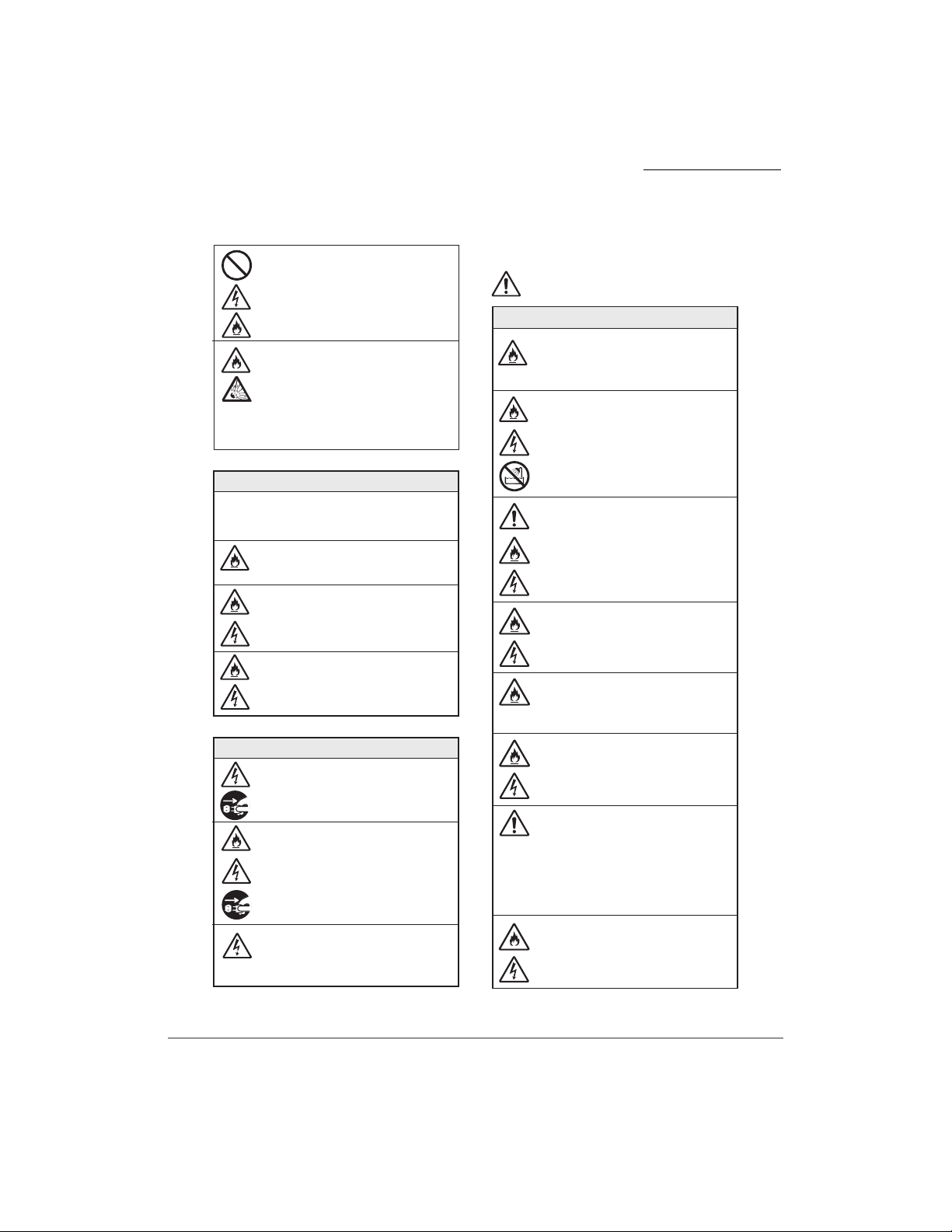
Using the Equipment Safely
ٟ
Precautions for use
The following safety information describes
how to prevent danger and damage to
your properties.
ٟ
Safety Symbol
Learn the meaning of the following symbols
and then read this section carefully before
using the equipment.
DANGER
Incorrect use of the equipment may cause personal injury
or death.
WARNING
Incorrect use of the equipment may cause personal injury
or a serious system fault.
May cause personal injury,
system damage, or loss of data.
Incorrect use of the equipment may cause
electric shock.
Incorrect use of the equipment may cause
ignition.
White-out symbols indicate commands
and directions. (The left symbol indicates
ground connections.)
DANGER
Electricity Source
Use the Product at AC100V-240V.
Never use at other power levels. Fires, electric
shock and system failure may result when used
at incorrect power levels.
Do not plug too many leads into a single
socket using branched plug sockets.
AC socket will overheat and may cause fire
and electric shock.
Insert sockets securely into the AC sockets.
Bad connection causes the electric plug and
socket to heat up. Metallic objects touching
the socket blades may cause fire and electric
shock.
Always hold the plug securely when disconnecting
from socket. Moreover, do not process, bend,
twist or pull the electric cords. Damage to the cords
may cause fire and electric shock.
Equipment
Do not touch the Product or electric plug
with wet hands. It may cause electric shock.
Never disassemble or alter the Project. It is
very dangerous and may result in fire, electric
shock and equipment failure.
viii
Indicates prohibited acts.
(The left symbol prohibits disassembly.)
Do not put other equipment on top of this
Product. Heat retention causes fire and
equipment failure.
Do not block the Product's ventilation duct.
Internal temperature rises, and may cause fire.
Page 11
Do not use option boards and equipment
other than the ones specified. It may result
in fire, electric shock and equipment failure.
Removing lithium batteries
This Product includes lithium battery. Do not
remove the lithium battery. Lithium battery may
explode near fire or when immersed in water.
Furthermore, if the device fails to operate due to
lithium life span, do not disassemble, exchange
or recharge. Contact the distributor or
maintenance service company.
When this happens
In the following cases, immediately disconnect the
electric plug from the AC socket and contact the
distributor for repairs. It is dangerous to attempt
to repair yourself.
Continued use regardless of smoke or
strange smell from the Product may result
in fire.
Continued use regardless of water and
other liquid, metal piece, burnable objects
inside the Product may result in fire,
electric shock and equipment failure.
Continued use after dropping the Product,
damaging the cords or the case may result
in fire, electric shock and equipment failure.
Countermeasure Against Lightning
Connect the attached electric cord to electric
socket where grounded connection is available.
ٟ
Instructions for Use
WARNING
Placement of the Product
Do not place the Product in direct sunlight
or high temperature. Internal temperature
rises, and may cause fire.
Do not place the Product in high humidity
or where temperature varies, such as bathroom
or near a humidifier.
It may result in fire, electric shock and
equipment failure. If condensation occurs,
unplug the cord and dry naturally or use
after letting the equipment adjust to the
temperature.
Do not place the Product where there is
movement, shock or inclination. When placing
at Access Points or ceilings, use the enclosed
tools and check regularly to see if the placement
is secure. Otherwise, the Product will fall and
may result in fire, electric shock and equipment
failure.
Do not place the Product where there is likely
to be oil spill and steam, such as a kitchen.
It may result in fire, electric shock
and equipment failure.
Do not place the Product in areas that
are dusty, filled with vaporized fumes or
have the possibility of touching chemicals.
It may result in fire, electric shock and
equipment failure.
Do not place the Product near heat
device, fire or stove. Product case and
cord coating may melt, resulting in fire,
electric shock and equipment failure.
Introduction
When lightning is anticipated, turn the
power off and discontinue use after
disconnecting the electric plug and line
cable. Lightning may result in fire,
electric shock and equipment failure.
When you hear lightning, do not touch
the electric plug or make connections to
the device. It may result in electric
shock.
Do not place the Product near radio or TV,
microwave oven, high frequency sewing
machine or electric welding machine
where strong magnetic field or high
frequency noise occurs. It may cause
reception error or malfunction.
Place Access Points where radio transmission
is not obstructed by large steel objects
such as a cabinet, or fire wall.
Keeping Pets Away
Keep pets away from this Product. Excretory
substance and fur may enter the Product and
may result in fire, electric shock and equipment
failure.
ix
Page 12
Introduction
About This Device
Electric wiring for this device shall
always be interior circuit. Exterior
wiring may cause electric shock.
Do not insert fingers or metallic object,
such as a clip, into the ports. It may result
in electric shock and equipment failure.
Maintenance Precautions
When electric plug is kept plugged in for
too long, dust and moisture attaches to
the electric plug and AC socket, creating
a conductive path, leading to deterioration
in insulating material, which may result
in fire. Regularly clean out the electric
plug and AC sockets to remove dust. Also
occasionally check to see if the electric
plug is firmly plugged in.
Never remove the product cover. There are
high-voltage parts inside which may cause
electric shock. It may also result in fire,
and equipment failure. Contact the distributor
for cleaning and repairing the Product.
Do not use option boards and equipment
other than the ones specified. It may
result in fire, electric shock and
equipment failure. To prevent those from
occurring, take the following:
-
Use the standard electric codes in the
shipping countries(UL/VDE/Electrical
Safety Regulations).
-
Use insulation of class I for devices
and power codes to adjust them.
When turning on electricity for this Product,
wait at least 10 seconds after the power
lamp is off. Otherwise it may cause equipment
failure.
Warning for High Temperature
Interior parts, such as internal hard
disks are extremely hot immediately after
turning the power OFF. Install or remove
after the Product is adequately cooled off.
x
Page 13

Introduction
UNIVERGE WL Controller
Voluntary Control Council for Interference by Information
Technology
Federal Communications Commission Notice (United States)
This device uses, generates, and radiates radio frequency energy. The radio
frequency energy produced by this device is well below the maximum exposure
allowed by the Federal Communications Commission (FCC).
Operation is subject to the following conditions:
l This device may not cause harmful interference.
l This device must accept any interference received, including interference that
may cause undesired operation.
This equipment has been tested and found to comply with the limits of a Class B
(SCA-WL10) or Class A (WL5100) (as marked) digital device, pursuant to Part
15 of the FCC Rules. These limits are designed to provide reasonable protection
against harmful interference when the equipment is operated in a residential
environment.
This accepted equipment is designed and tested to provide reasonable protection
against harmful interference when the equipment is operated in a commercial
environment. This equipment generates, uses, and can radiate radio frequency
energy and, if not installed in accordance with the instruction manual, may cause
harmful interference.
There is no guarantee that interference will not occur. If this equipment does
cause interference to radio or television reception, which can be determined by
turning the equipment off and on, the user is encouraged to correct the
interference by one of the following measures:
l Reorient or relocate the device to reorient or relocate the receiving antenna.
l Increase separation between the equipment and receiver.
xi
Page 14

Introduction
Caution! Any charges or modifications not expressly approved by the party
responsible for compliance could void the user’s authority to operate this equipment.
For operation within the 5.15 – 5.25 GHz frequency range, use is restricted to an indoor
environment.
Canadian Department of Communications Industry Canada Notice
(Canada)
This digital apparatus meets the requirements of Canadian Interference-Causing
Equipment Regulation RSS-210.
Cet appareil respecte les exigences du Reglement sur le material broilleur du
Canada.
This device complies with the limits of Industry Canada (IC). Operation is subject
to the following conditions:
l This device may not cause harmful interference.
l This device must accept any interference received, including interference that
may cause undesired operation.
European Union information
Notice to the user
The WLAN controllers described in this manual are intended to be used in
combination with the NEC Assured Mobility concept for Wireless Local Area
Networks.
xii
Page 15

Introduction
Declaration of conformity
Hereby, “NEC Philips Unified Solutions”, declares that the WL5050 and
WL5100 are in compliance with the essential requirements and other relevant
provisions of Directive 1999/5/EC.
http://www.nec-philips.com/doc
Electromagnetic Compatibility
For WLAN controller WL5100 the following warning is applicable:
Warning! This is a class A product. In a domestic environment this product may
cause radio interference in which case the user may be required to take adequate
measures.
xiii
Page 16

Introduction
UNIVERGE WL Access Point
Voluntary Control Council for Interference by Information
Technology
Federal Communications Commission Notice (United States)
This device uses, generates, and radiates radio frequency energy. The radio
frequency energy produced by this device is well below the maximum exposure
allowed by the Federal Communications Commission (FCC).
Operation is subject to the following conditions:
l This device may not cause harmful interference.
l This device must accept any interference received, including interference that
may cause undesired operation.
This equipment has been tested and found to comply with the limits of a Class B
digital device, pursuant to Part 15 of the FCC Rules. These limits are designed to
provide reasonable protection against harmful interference when the equipment is
operated in a residential environment.
xiv
This accepted equipment is designed and tested to provide reasonable protection
against harmful interference when the equipment is operated in a commercial
environment. This equipment generates, uses, and can radiate radio frequency
energy and, if not installed in accordance with the instruction manual, may cause
harmful interference.
There is no guarantee that interference will not occur. If this equipment does
cause interference to radio or television reception, which can be determined by
turning the equipment off and on, the user is encouraged to correct the
interference by one of the following measures:
l Reorient or relocate the device to reorient or relocate the receiving antenna.
l Increase separation between the equipment and receiver.
Page 17

Introduction
Caution! Any charges or modifications not expressly approved by the party
responsible for compliance could void the user’s authority to operate this equipment.
For operation within the 5.15 – 5.25 GHz frequency range, use is restricted to an indoor
environment.
Radio Frequency Compliance Information (European Union)
The UNIVERGE WL Access Point has been tested and found to comply with
European Telecommunications Standard (ETS) 300 328 for 2.4-GHz equipment
and ETS 301 893 for 5-GHz equipment. These standards cover wide band data
transmission systems referred to in European Conference of Postal and
Telecommunications Administrations (CEPT) recommendation T/R 10.01.
Warning for electromagnetic waves
Use of wireless LAN (5GHZ) feature is limited to internal use by electromagnetic
wave laws.
This equipment operates in the same frequency bandwidth as industrial, scientific,
and medical devices such as microwave ovens and mobile object identification
(RF-ID) systems (licensed premises radio stations and unlicensed specified
low-power radio stations) used in factory production lines.
1. Before using this equipment, make sure that no premises radio stations or
specified low-power radio stations of RF-ID are used in the vicinity.
2. If this equipment causes RF interference to a premises radio station of
RF-ID, promptly change the frequency or stop using the device; contact
your distributor or NEC and ask for recommendations on avoiding radio
interference, such as setting partitions.
3. If this equipment causes RF interference to a specified low-power radio
station of RF-ID, contact the distributor or a local business center.
4. On 2.4 GHz features, “2.4 GHz frequency band / modulation method /
assumed interference distance / possibility of changing frequency” is
indicated.
xv
Page 18
Introduction
(1)
(2)
(3)
2.4DS/OF4
(4)
(1) 2.4 :Indication of radio equipment using 2.4GHz.
(2) DS
OF
(3) 4 :Indicates assumed interference distance towards
(4)
Security Precautions Regarding Wireless LAN
(Important Section for Protecting Client’s Privacy!)
In wireless LAN, rather than using LAN cables, information is exchanged
between PC and Access Point through radio wave transmission. The benefit is the
freedom to create LAN connection anywhere within radio wave transmission
area.
:Indicates DS-SS method.
:Indicates OFDM method.
premises radio station of RF-ID. "4" indicates the
distance is less than 40m.
:Indicates the use of all frequency bandwidths. Also,
it is possible to avoid the frequency bandwidths
used by premises radio station of RF-ID.
xvi
On the other hand, because radio waves travel through obstacles (such as
ceilings), without security measures, the following problems may arise.
l Transmitted data may be seen
A malicious intruder may purposely intercept the radio waves. E-mails with
personal information such as ID, password or credit card number may be
seen.
l Possibility of intrusion
Page 19

Introduction
A malicious intruder may access a personal or company network to steal
personal or classified information (divulging of information), transmit and
send false data by pretending to be a specific person (spoofing), retransmit
data after falsifying transmitted data (falsification), corrupt data or system by
sending computer virus (corruption).
Under regular circumstances, wireless LAN card and wireless Access Points
have security measures which resolve these problems. Using the security
settings for wireless LAN products will decrease the probability for these
problems.
Initially upon purchasing, security settings may not be administered for the
wireless LAN device.
Thus, to lessen the possibility of security problems to occur, please complete
all security settings for wireless LAN, in accordance to the manual, before
using wireless LAN cards and Access Points.
Please use this product upon understanding that due to the nature of wireless
LAN, it is possible for security settings to be broken by unusual methods.
If you have difficulties setting up security measures, please contact the
distributor or a local business center.
We advise our customers to first understand the problems of not setting up
security. Use this Product after administering security settings, based on the
your judgment and responsibility.
If security problem occurs by not administering security measures or through
circumstances beyond control, NEC will not be held responsible for the
resulting damage.
xvii
Page 20

Introduction
European Union information
Notice to the user
The WLAN access points described in this manual are intended to be used in
combination with the NEC Assured Mobility concept for Wireless Local Area
Networks.
The country specific radio spectrum properties of this equipment are
automatically configured by means of the WLAN management application.
Supported countries are listed in chapter 3 with their respective country code.
Under no circumstances should you specify a country code that does not match
the country of operation. If the software does not support the country of operation,
this might be because the country has not yet approved the use of this equipment.
In this case, contact your local supplier before installing the equipment.
The WL1500 Access Point was not designed for installation and use in an outdoor
environment.
Declaration of conformity
xviii
Hereby, “NEC Philips Unified Solutions”, declares that the WL1500 is in
compliance with the essential requirements and other relevant provisions of
Directive 1999/5/EC.
http://www.nec-philips.com/doc
Page 21

Product disposal information
For countries in the European Union
The symbol depicted here has been affixed to your
product in order to inform you that electrical and
electronic products should not be disposed of as
municipal waste.
Electrical and electronic products including the
cables, plugs and accessories should be disposed of
separately in order to allow proper treatment,
recovery and recycling. These products should be
taken to a designated facility where the best
available treatment, recovery and recycling
techniques are available. Separate disposal has
significant advantages: valuable materials can be
re-used and it prevents the dispersion of unwanted
substances into the municipal waste stream. This
contributes to the protection of human health and
the environment.
Please be informed that a fine may be imposed for
illegal disposal of electrical and electronic products
via the general municipal waste stream.
Introduction
In order to facilitate separate disposal and environmentally sound recycling
arrangements have been made for local collection and recycling. In case your
electrical and electronic products need to be disposed of please refer to your
supplier or the contractual agreements that your company has made upon
acquisition of these products.
At http://www.nec-philips.com/weee you can find information about separate
disposal and environmentally sound recycling.
For countries outside the European Union
Disposal of electrical and electronic products in countries outside the
European Union should be done in line with the local regulations. If no
arrangement has been made with your supplier, please contact the local
authorities for further information.
xix
Page 22

Introduction
Regulatory Notices for Taiwan
低功率電波輻射性電機管理法:
第十四條:經型式認證合格之低功率射頻電機,非經許可,公司、商號或使用者均
不得擅自變更頻率、加大功率或變更原設計之特性及功能。
第十七條:低功率射頻電機之使用不得影響飛航安全及干擾合法通信;
經發現有干擾現象時,應立即停用,並改善至無干擾時方得繼續使用。
前項合法通信,指依電信法規定作業之無線電通信。低功率射頻電機
須忍受合法通信或工業、科學及醫療用電波輻射性電機設備之干擾。
xx
Page 23

Introduction
Software License Agreement for This Product
SSH Source Code Statement
Copyright (c) 1983, 1990, 1992, 1993, 1995 The Regents of the University of California.
All rights reserved.
THIS SOFTWARE IS PROVIDED BY THE REGENTS AND CONTRIBUTORS ``AS
IS'' AND ANY EXPRESS OR IMPLIED WARRANTIES, INCLUDING, BUT NOT
LIMITED TO, THE IMPLIED WARRANTIES OF MERCHANTABILITY AND
FITNESS FOR A PARTICULAR PURPOSE ARE DISCLAIMED. IN NO EVENT
SHALL THE REGENTS OR CONTRIBUTORS BE LIABLE FOR ANY DIRECT,
INDIRECT, INCIDENTAL, SPECIAL, EXEMPLARY, OR CONSEQUENTIAL
DAMAGES (INCLUDING, BUT NOT LIMITED TO, PROCUREMENT OF
SUBSTITUTE GOODS OR SERVICES; LOSS OF USE, DATA, OR PROFITS; OR
BUSINESS INTERRUPTION) HOWEVER CAUSED AND ON ANY THEORY OF
LIABILITY, WHETHER IN CONTRACT, STRICT LIABILITY, OR TORT
(INCLUDING NEGLIGENCE OR OTHERWISE) ARISING IN ANY WAY OUT OF
THE USE OF THIS SOFTWARE, EVEN IF ADVISED OF THE POSSIBILITY OF
SUCH DAMAGE.
Components of the software are provided under a standard 2-term BSD license with the
following names as copyright holders:
l Markus Friedl
l Theo de Raadt
l Niels Provos
l Dug Song
l Aaron Campbell
l Damien Miller
l Kevin Steves
l Daniel Kouril
l Per Allansson
xxi
Page 24

Introduction
Registered Trademarks and Service Marks
UNIVERGETM is trademarks of NEC Infrontia Corporation. All other trademarks,
service marks, and product names used in this document are the property of their
respective owners. In this manual, (R) and
TM
marks are not used.
xxii
Page 25

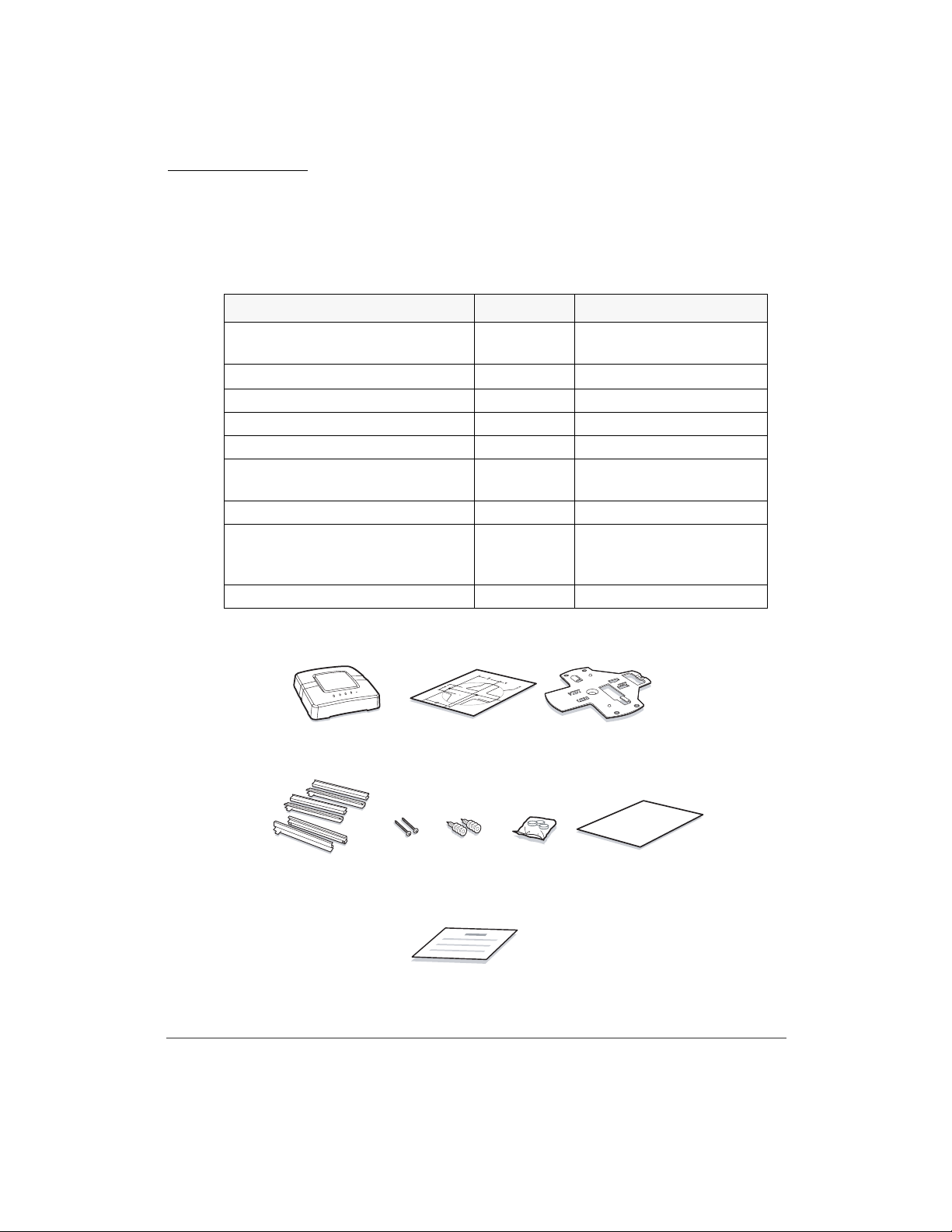
Confirm Contents of The Package
UNIVERGE WL Controller
The package contains the following:
UNIVERGE SCA-WL10
CONTENTS QUANTITY REMARK
UNIVERGE WL Controller 1 This is the main product.
UNIVERGE WL5100
CONTENTS QUANTITY REMARK
UNIVERGE WL Controller 1 This is the main product.
19-inch Rack Mounting Plates 2 Attached on the product.
Screws for 19-inch Rack Mounting
Plate
Screws for 19-inch Rack Mounting 4 (inch standard item)
Spring Washers for Screw 4 (inch standard item)
Plain Washers for Screw 4 (inch standard item)
Screws for 19-inch Rack Mounting 4 (mm standard item)
WL First Step Guide 1 This describes precaution
6 Attached on the product.
with spring and plain washers
statement and attachment of
the package.
Introduction
OPTION REMARKS
UNIVERGE WL5100 Power
Module
Power Module (for redundant or
replacement)
xxiii
Page 26
Introduction
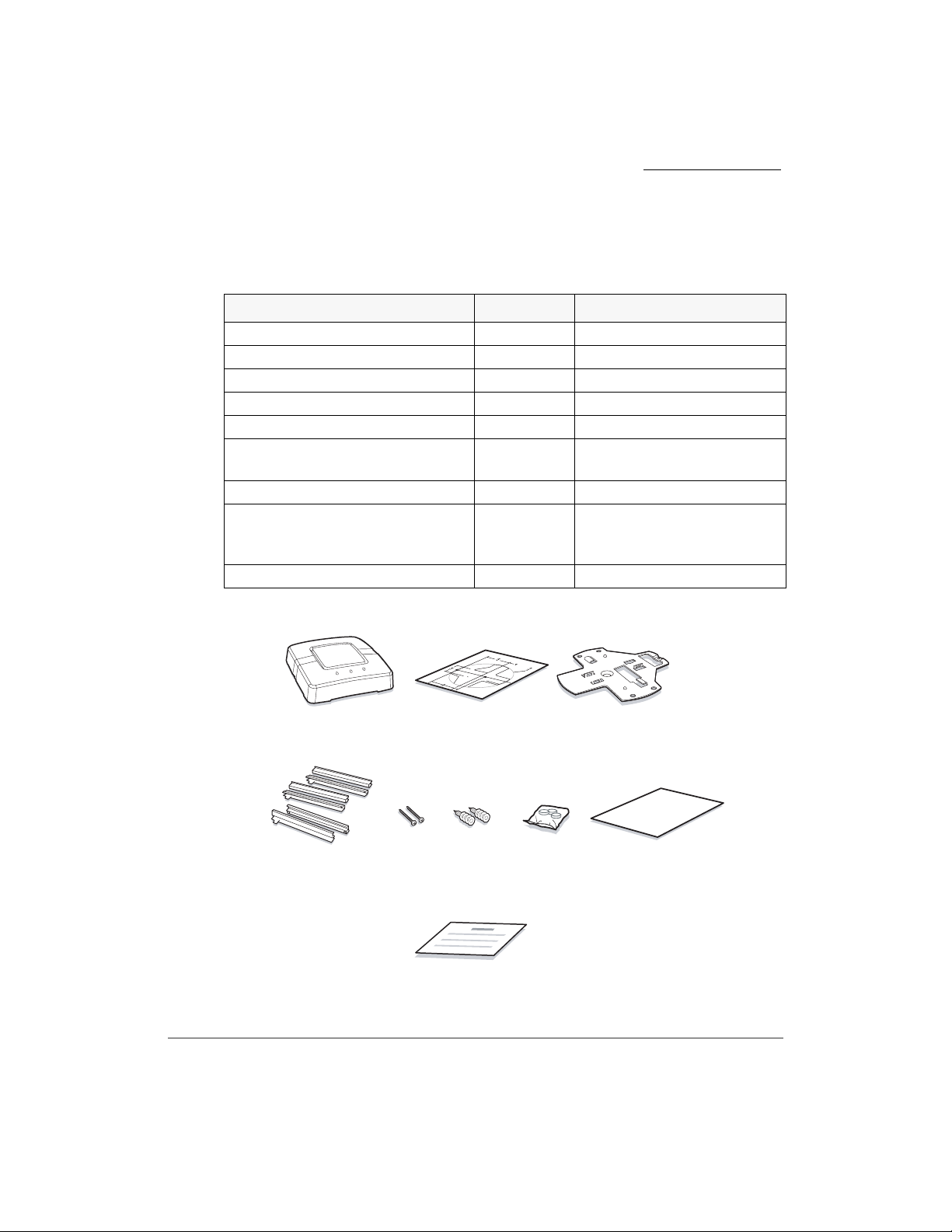
UNIVERGE WL Intelligent Access Point
The package contains the following:
CONTENTS QUANTITY REMARK
UNIVERGE WL
Intelligent Access Point
Mounting Template
Mounting Bracket 1
T-Bar Clamps 6
Mounting Hardware (Screws) 2
Mounting Hardware
(Wall Anchors)
Rubber Feet 3 For tabletop Installation
WL First Step Guide 1 This describes precaution
ARIB Sticker 1
1 This is the main product.
1
2
statement and attachment
of the package.
xxiv
1
UNIVERGE WL
Intelligent Access Point
4
T-Bar Clamps
(Use it with T-bar)
23
Mounting Template
56 7 8
Wall AnchorsMounting Screws
Mounting Hardware
ARIB Sticker
Rubber Feet
Mounting Bracket
WL First Step Guide
Page 27
UNIVERGE WL Access Point
The package contains the following:
CONTENTS QUANTITY REMARK
UNIVERGE WL Access Point 1 This is the main product.
Mounting Template 1
Mounting Bracket 1
T-Bar Clamps 6
Mounting Hardware (Screws) 2
Mounting Hardware
(Wall Anchors)
Rubber Feet 3 For tabletop Installation
WL First Step Guide 1 This describes precaution
ARIB Sticker 1
Introduction
2
statement and attachment of
the package.
1
UNIVERGE WL Access Point
4
T-Bar Clamps
(Use it with T-bar)
23
Mounting Template
56 7 8
Wall AnchorsMounting Screws
Mounting Hardware
ARIB Sticker
Rubber Feet
Mounting Bracket
WL First Step Guide
xxv
Page 28

Introduction
UNIVERGE WL Management System (WLMS)
The package contains the following:
CONTENTS QUANTITY REMARK
UNIVERGE WLMS Software 1 This is a main product
software (CD-R)
License Sheet 1 License Sheet for 50 License
Points
WLMS Manual 1 The PDF format manual
describing this product is
included in CD-R.
Note. Additional License is necessary when more than 50AP licenses are to be used.
xxvi
Page 29

About Manuals
This manual contains information as follows:
Introduction
UNIVERGE WL
Installation Guide
This manual contains specifications and basic
settings of UNIVERGE WL Controller and
UNIVERGE WL Access Point.
xxvii
Page 30

Introduction
xxviii
Page 31

Contents
About WL Controller . . . . . . . . . . . . . . . . . . . . . . . . . . . . . . . . . . . . . . . . . . . 2
UNIVERGE WL5100 . . . . . . . . . . . . . . . . . . . . . . . . . . . . . . . . . . . . . . . 2
SCA-WL10 . . . . . . . . . . . . . . . . . . . . . . . . . . . . . . . . . . . . . . . . . . . . . . . 3
WL Intelligent Access Point . . . . . . . . . . . . . . . . . . . . . . . . . . . . . . . . . . . . . . 4
UNIVERGE WL1700-MS . . . . . . . . . . . . . . . . . . . . . . . . . . . . . . . . . . . . 4
WL Access Point . . . . . . . . . . . . . . . . . . . . . . . . . . . . . . . . . . . . . . . . . . . . . . 5
UNIVERGE WL1500-AP . . . . . . . . . . . . . . . . . . . . . . . . . . . . . . . . . . . . 5
Network Topology with WL Controllers . . . . . . . . . . . . . . . . . . . . . . . . . . . . 6
Data-Processing System . . . . . . . . . . . . . . . . . . . . . . . . . . . . . . . . . . . . . . 7
Centralized Path . . . . . . . . . . . . . . . . . . . . . . . . . . . . . . . . . . . . . . . . . 7
Mobility Domain . . . . . . . . . . . . . . . . . . . . . . . . . . . . . . . . . . . . . . . . . . . 8
Voice Extension . . . . . . . . . . . . . . . . . . . . . . . . . . . . . . . . . . . . . . . . . . . 10
Voice QoS . . . . . . . . . . . . . . . . . . . . . . . . . . . . . . . . . . . . . . . . . . . . 10
Bandwidth Control . . . . . . . . . . . . . . . . . . . . . . . . . . . . . . . . . . . . . 10
Fast Handover . . . . . . . . . . . . . . . . . . . . . . . . . . . . . . . . . . . . . . . . . 10
Voice Terminal Power Saving Control . . . . . . . . . . . . . . . . . . . . . . 10
About WLMS . . . . . . . . . . . . . . . . . . . . . . . . . . . . . . . . . . . . . . . . . . . . . . . . 11
UNIVERGE WL Management System . . . . . . . . . . . . . . . . . . . . . . . . . 11
Specifications . . . . . . . . . . . . . . . . . . . . . . . . . . . . . . . . . . . . . . . . . . . . . . . . 12
Network Specifications . . . . . . . . . . . . . . . . . . . . . . . . . . . . . . . . . . . . . 12
Specifications for WL Controllers . . . . . . . . . . . . . . . . . . . . . . . . . . . . . 18
Specifications for Intelligent Access Points . . . . . . . . . . . . . . . . . . . . . . 19
Specifications for Access Points . . . . . . . . . . . . . . . . . . . . . . . . . . . . . . 20
Specifications for WLMS (Network Management System) . . . . . . . . . 21
Names and Functions of Each Part of WL5100 . . . . . . . . . . . . . . . . . . . . . . 22
External View . . . . . . . . . . . . . . . . . . . . . . . . . . . . . . . . . . . . . . . . . . . . 22
LED Indication . . . . . . . . . . . . . . . . . . . . . . . . . . . . . . . . . . . . . . . . . . . . 23
External Interface . . . . . . . . . . . . . . . . . . . . . . . . . . . . . . . . . . . . . . . . . . 23
Topology . . . . . . . . . . . . . . . . . . . . . . . . . . . . . . . . . . . . . . . . . . . . . . . . 24
Contents
xxix
Page 32

Names and Functions of Each Part of SCA-WL10 . . . . . . . . . . . . . . . . . . . 25
External View . . . . . . . . . . . . . . . . . . . . . . . . . . . . . . . . . . . . . . . . . . . . 25
LED Indication . . . . . . . . . . . . . . . . . . . . . . . . . . . . . . . . . . . . . . . . . . . . 26
External Interface . . . . . . . . . . . . . . . . . . . . . . . . . . . . . . . . . . . . . . . . . . 27
Topology . . . . . . . . . . . . . . . . . . . . . . . . . . . . . . . . . . . . . . . . . . . . . . . . 28
Names and Functions of Each Part of WL1700-MS . . . . . . . . . . . . . . . . . . 29
External View . . . . . . . . . . . . . . . . . . . . . . . . . . . . . . . . . . . . . . . . . . . . 29
LEDs . . . . . . . . . . . . . . . . . . . . . . . . . . . . . . . . . . . . . . . . . . . . . . . . . . . 31
External Interface . . . . . . . . . . . . . . . . . . . . . . . . . . . . . . . . . . . . . . . . . . 32
Topology . . . . . . . . . . . . . . . . . . . . . . . . . . . . . . . . . . . . . . . . . . . . . . . . 32
Names and Functions of Each Part of Access Point . . . . . . . . . . . . . . . . . . . 33
External View . . . . . . . . . . . . . . . . . . . . . . . . . . . . . . . . . . . . . . . . . . . . 33
LEDs . . . . . . . . . . . . . . . . . . . . . . . . . . . . . . . . . . . . . . . . . . . . . . . . . . . 35
External Interface . . . . . . . . . . . . . . . . . . . . . . . . . . . . . . . . . . . . . . . . . . 36
Topology . . . . . . . . . . . . . . . . . . . . . . . . . . . . . . . . . . . . . . . . . . . . . . . . 36
Check Packages . . . . . . . . . . . . . . . . . . . . . . . . . . . . . . . . . . . . . . . . . . . . . . 37
Check Mounting Locations . . . . . . . . . . . . . . . . . . . . . . . . . . . . . . . . . . . . . 37
Location for WL Controller . . . . . . . . . . . . . . . . . . . . . . . . . . . . . . . . . . 37
Location for WL Access Point . . . . . . . . . . . . . . . . . . . . . . . . . . . . . . . . 39
Installation Procedures . . . . . . . . . . . . . . . . . . . . . . . . . . . . . . . . . . . . . . . . . 40
WL5100/SCA-WL10 . . . . . . . . . . . . . . . . . . . . . . . . . . . . . . . . . . . . . . . 40
WL1700-MS . . . . . . . . . . . . . . . . . . . . . . . . . . . . . . . . . . . . . . . . . . . . . 41
Mounting . . . . . . . . . . . . . . . . . . . . . . . . . . . . . . . . . . . . . . . . . . . . . . . . . . . 43
WL5100 Mounting . . . . . . . . . . . . . . . . . . . . . . . . . . . . . . . . . . . . . . . . . 43
SCA-WL10 Inserting . . . . . . . . . . . . . . . . . . . . . . . . . . . . . . . . . . . . . . . 43
Mounting Into 19-Inch Rack . . . . . . . . . . . . . . . . . . . . . . . . . . . . . . . . . 44
Cable Connection . . . . . . . . . . . . . . . . . . . . . . . . . . . . . . . . . . . . . . . . . . . . . 48
Power Cable Connection . . . . . . . . . . . . . . . . . . . . . . . . . . . . . . . . . . . . 49
Connecting PC with WL Controller . . . . . . . . . . . . . . . . . . . . . . . . . . . . 53
Powering On . . . . . . . . . . . . . . . . . . . . . . . . . . . . . . . . . . . . . . . . . . . . . 55
Access Point Installation . . . . . . . . . . . . . . . . . . . . . . . . . . . . . . . . . . . . . . . 58
Connecting PC with WL1700-MS . . . . . . . . . . . . . . . . . . . . . . . . . . . . . 58
Attaching APs to Ceiling (Flush Ceiling Tiles) . . . . . . . . . . . . . . . . . . . 59
xxx
Installation Guide
Page 33

Attaching APs to Ceiling (DrRP Ceiling Tiles) . . . . . . . . . . . . . . . . . . . 62
Attaching APs to Rigid Wall or Ceiling . . . . . . . . . . . . . . . . . . . . . . . . 65
Tabletop Mounting . . . . . . . . . . . . . . . . . . . . . . . . . . . . . . . . . . . . . . . . . 68
Connecting to Access Points . . . . . . . . . . . . . . . . . . . . . . . . . . . . . . . . . 71
DHCP Server Setting . . . . . . . . . . . . . . . . . . . . . . . . . . . . . . . . . . . . 71
Self Diagnosis . . . . . . . . . . . . . . . . . . . . . . . . . . . . . . . . . . . . . . . . . . . . . . . . 73
Data Assignment . . . . . . . . . . . . . . . . . . . . . . . . . . . . . . . . . . . . . . . . . . . . . . 74
Setup Data Assignment Using CLI . . . . . . . . . . . . . . . . . . . . . . . . . . . . 75
Before Doing This Task . . . . . . . . . . . . . . . . . . . . . . . . . . . . . . . . . 75
Text and Syntax Conventions . . . . . . . . . . . . . . . . . . . . . . . . . . . . . 76
About CLI . . . . . . . . . . . . . . . . . . . . . . . . . . . . . . . . . . . . . . . . . . . . 78
Error Messages For Command Input . . . . . . . . . . . . . . . . . . . . . . . 79
Overview for Basic Data Assignment Using CLI . . . . . . . . . . . . . . 80
Procedures for Data Assignment Using CLI . . . . . . . . . . . . . . . . . . 83
Check Configurations/Network Status . . . . . . . . . . . . . . . . . . . . . 106
Setup Data Assignment Using WebView . . . . . . . . . . . . . . . . . . . . . . 109
Before Doing This Task . . . . . . . . . . . . . . . . . . . . . . . . . . . . . . . . 109
About WebView . . . . . . . . . . . . . . . . . . . . . . . . . . . . . . . . . . . . . . 112
Overview for Basic Data Assignment Using WebView . . . . . . . . 114
Text and Syntax Conventions . . . . . . . . . . . . . . . . . . . . . . . . . . . . 117
Procedures for Data Assignment Using WebView . . . . . . . . . . . . 118
Data Assignment For Intelligent AP (Using Initial Setup) . . . . . . . . . 146
Before Doing This Task . . . . . . . . . . . . . . . . . . . . . . . . . . . . . . . . 147
Procedures for Data Assignment Using Initial Setup . . . . . . . . . . 149
Cleaning The Site . . . . . . . . . . . . . . . . . . . . . . . . . . . . . . . . . . . . . . . . . . . . 161
Configuration Management . . . . . . . . . . . . . . . . . . . . . . . . . . . . . . . . . . . . 163
Copy . . . . . . . . . . . . . . . . . . . . . . . . . . . . . . . . . . . . . . . . . . . . . . . . . . . 164
Backup . . . . . . . . . . . . . . . . . . . . . . . . . . . . . . . . . . . . . . . . . . . . . . . . . 168
Backup into Flash Card . . . . . . . . . . . . . . . . . . . . . . . . . . . . . . . . . 168
Backup into TFTP Server . . . . . . . . . . . . . . . . . . . . . . . . . . . . . . . 169
Restore Configuration File . . . . . . . . . . . . . . . . . . . . . . . . . . . . . . 169
Delete Configuration Files . . . . . . . . . . . . . . . . . . . . . . . . . . . . . . 170
Return to factory-set condition . . . . . . . . . . . . . . . . . . . . . . . . . . . . . . 171
Contents
xxxi
Page 34

Using CLI . . . . . . . . . . . . . . . . . . . . . . . . . . . . . . . . . . . . . . . . . . . 171
Using WebView . . . . . . . . . . . . . . . . . . . . . . . . . . . . . . . . . . . . . . 172
Using Switch . . . . . . . . . . . . . . . . . . . . . . . . . . . . . . . . . . . . . . . . . 173
Power Unit Replacement . . . . . . . . . . . . . . . . . . . . . . . . . . . . . . . . . . . . . . 175
Power Unit Replacement for WL5100 . . . . . . . . . . . . . . . . . . . . . . . . . 175
Power Unit Replacement for SCA-WL10 . . . . . . . . . . . . . . . . . . . . . . 180
Examples of System Configurations . . . . . . . . . . . . . . . . . . . . . . . . . . . . . 183
Pattern 1: System Configurations for VLANs (Centralized Path) . . . . 184
Pattern 2: System Configuration for Mobility Group . . . . . . . . . . . . . 188
Pattern 3: System Configuration for Voice Extension . . . . . . . . . . . . . 190
xxxii
Installation Guide
Page 35

OVERVIEW
UNIVERGE WL system is an enterprise-class wireless system that provides a
most strong security and a flexible interpretability.
The system provides an interface that totally controls Access Points (APs) located
in remote offices, which drastically reduces a burden for wireless network design
and operation. Besides, VLAN function enables you to freely change network
configurations without considering the locations of terminals. As for security, it
supports WPA and other encryptions to provide users with secured connections.
The standards for those elements meet enterprise-class demand, and provides you
with best quality and high reliable wireless network solution.
1
DHCP Server
100M LINK100M LINK
PWR ACTALM LOAD
Ether1
Ether2
WL Controller
SW HUB
100M LINK100M LINK
PWR ACTALM LOAD
Ether1
Ether2
Access Point
HUB xxxxxx HUB xxxxxx
GatoNegro
Simulator
OVERVIEW
SW HUB
GatoNegro
Simulator
1
Page 36

About WL Controller
Chapter 1
About WL Controller
UNIVERGE WL Controller (hereinafter “WL Controller”) is equipment that
control UNIVERGE WL Access Points (hereinafter “WL AP” or “WL Access
Point”), and creates an IEEE802.11-standard wireless network.
WL Controller can manage (includes the AP data assignment) Access Points in a
LAN.
UNIVERGE WL5100
UNIVERGE WL5100 (hereinafter “WL5100”) is used for middle or
enterprise-class wireless network. WL5100 can control up to 12 APs in the
network.
Two 10/100/1000 Base-Tx ports are provided on the front panel of WL5100 (One
port is unavailable). The following shows the front view of WL5100.
USB
PWR ACTALM LOAD
2
Ether 1
Ether 2
SPEED
LINK/ACT
OVERVIEW
PWR1
PWR2
Page 37

SCA-WL10
SCA-WL10 (This has the same specifications as those of the UNIVERGE
WL5050) is used for small-class or middle-class voice wireless network.
SCA-WL10 is accommodated in Multi-Purpose Chassis (MPC) and SV7000
MPS, and it can control up to four APs in the network.
Two 10/100 Base-Tx ports are provided on the front panel of SCA-WL10 (One
port is unavailable). The following shows the front of SCA-WL10.
About WL Controller
Chapter 1
PWR ACTALM LOAD
100M LINK 100M LINK
Ether1
Ether2
OVERVIEW
3
Page 38

WL Intelligent Access Point
Chapter 1
WL Intelligent Access Point
WL Intelligent Access Point is an intelligent type of Access Points (APs), which
has an internal Wireless Controller to manage other APs as well as internal Access
Point feature. Therefore, WL Intelligent Access Point can provide data settings
and management for other APs connected to a network.
It can be provided electricity by Power over Ethernet (PoE).
UNIVERGE WL1700-MS
WL1700-MS contains one 802.11a radio, one 802.11b/g radio and four (two
802.11a and two 802.11b/g) high-gain antennas.
WL1700-MS controls up to four APs (including the internal AP functionality in
itself) in the network.
One 10/100 Base-Tx port is provided on the front panel of WL1700-MS. The
following is a figure of the WL1700-MS.
4
OVERVIEW
Page 39

WL Access Point
When associated with a UNIVERGE WL Controllers, the UNIVERGE WL AP
provides advanced 802.11a and/or 802.11b/g Access Point functions
In the UNIVERGE WL System, most of the processing responsibility is removed
from traditional SOHO APs and resides in the UNIVERGE WL Controllers.
WL Access Points can receive electrical power from Power over Ethernet (PoE)
equipment.
UNIVERGE WL1500-AP
UNIVERGE WL1500-AP contains one 802.11a radio, one 802.11b/g radio, four
(two 802.11a and two 802.11b/g) high-gain antennas, one 5GHz external antenna
connector, and one 2.4GHz external antenna connector.
Two 10/100 Base-Tx port is provided on the front panel of WL1500-AP. The
following is a figure of the WL1500-AP.
WL Access Point
Chapter 1
OVERVIEW
5
Page 40

Network Topology with WL Controllers
Chapter 1
Network Topology with WL Controllers
WL Controllers can connect the following number of WL Access Points through
the network, depending on the controller type.
l WL5100 is capable of connecting 12 APs.
l SCA-WL10 is capable of connecting up to four APs.
l WL1700-MS is capable of connecting up to four APs (including an internal
AP functionality in itself).
When operating with Layer 2 (data link) mode, a WL Controller and the
associated WL Access Points must be located in the same segment (subnet).
When operating with Layer 3 (network) mode, a WL Controller and the
associated WL Access Points are not necessary to place in the same segment
(subnet). For more information on those modes, refer to “Connecting to Access
Points” on page 71.
The following is an example of network using a WL Controller and WL Access
Points.
WL Controller
PWR ACTALM LOAD
100M LINK100M LINK
Ether1
Ether2
PWR ACTALM LOAD
100M LINK100M LINK
Ether1
Ether2
GatoNegro
Simulator
6
OVERVIEW
Page 41

Data-Processing System
A
As data-processing system between WL Controller and WL Access Points,
UNIVERGE WL System can be configured to perform by the following:
Centralized Path
When Centralized Path is used, all the packets from terminals to Access Points are
transferred to WL Controller, and then the WL Controller transmits the packets to
those appropriate destinations.
USB
WL Controller
PWR ACTALM LOAD
Ether 1
PWR1
PWR2
Ether 2
SPEED
LINK/ACT
Network Topology with WL Controllers
Chapter 1
Data traffic from wireless terminals or data
traffic to external networks are sent back
to WL Controller, and then the Controller
sends the data to the appropriate paths.
ccess Points
OVERVIEW
7
Page 42

Network Topology with WL Controllers
Chapter 1
Mobility Domain
UNIVERGE WL System can create mobility domains, which contains multiple
WL Controllers. Mobility Domain is a special domain for Mobility terminals.
When the mobility user roams and connects to another Access Point that the
different Controller but assigned to the Mobility Group manages, the user do not
need to acquire a new IP address from the Controller again; the user can retain the
same IP address across the subnets or VLAN.
Mobility Domain consists of two types of UNIVERGE WL Controllers: seed (a
single WL Controller is functioned as Server function per Mobility Domain.) and
member (other WL Controllers are functioned as Client function in the Mobility
Domain.). When a member requires the information for controller belonging to
the Mobility domain, the seed-functioned Controller provides it to the member.
The following figures explains how a seed and members work in a Mobility
Domain:
l Process After data assignment of Mobility Domain
PWR ACTALM LOAD
Mobility Domain
HUB xxxxxx
PWR ACTALM LOAD
100M LINK100M LINK
Ether1
Ether2
member1
PWR ACTALM LOAD
VLAN Info
100M LINK100M LINK
PWR ACTALM LOAD
Ether1
Ether2
A seed adds all of the Controllers' VLAN
information to its management table.
seed
USB
Ether 1
PWR1
PWR2
Ether 2
SPEED
LINK/ACT
VLAN Info
member2
100M LINK100M LINK
Ether1
Ether2
(1) VLAN Infomation is provided
by each member
100M LINK100M LINK
PWR ACTALM LOAD
Ether1
Ether2
VLAN Info
PWR ACTALM LOAD
(2) All the VLAN information in the Mobility Domain
is distributed from the seed.
member3
100M LINK100M LINK
100M LINK100M LINK
PWR ACTALM LOAD
Ether1
Ether2
Ether1
Ether2
HUB xxxxxx
HUB xxxxxx
HUB xxxxxx
VLAN:Virtual Local Area Network
8
OVERVIEW
Page 43

Network Topology with WL Controllers
Chapter 1
l Process When a terminal roamed to another AP controlled by other WL
Controller in a Mobility Domain
When a terminal roams in a Mobility Domain, if the Controller cannot find any
VLAN information regarding to the roaming terminal, the Controller send a
request to the seed in the Mobility Domain to find out an appropriate Controller
containing the terminal information. Upon receiving information from the seed,
the Controller will try to make an IP tunneling to establish a connection with the
appropriate VLAN through the networks.
Mobility Domain
Controller
member1 PC1 10
member1 Phone1 20
member2 PC2 10
member2 Phone2 20
member3 PC3 10
member3 Phone3 20
ID VLAN
100M LINK100M LINK
PWR ACTALM LOAD
Ether1
Ether2
HUB xxxxxx
Terminal belongs to the following:
ID: Phone1
VLAN: 20
Controller
member1 PC1 10
member1 Phone1 20
member2 PC2 10
member2 Phone2 20
member3 PC3 10
seed
member3 Phone3 20
USB
Ether 1
PWR ACTALM LOAD
PWR1
PWR2
Ether 2
SPEED
LINK/ACT
HUB xxxxxx
member2
100M LINK100M LINK
PWR ACTALM LOAD
PWR ACTALM LOAD
Ether1
100M LINK100M LINK
PWR ACTALM LOAD
Ether1
Ether2
Ether2
䋨2䋩㩷㪠㪧㩷㪫㫌㫅㫅㪼㫃㫀㫅㪾
HUB xxxxxx
ID VLAN
Controller
member1 PC1 10
member1 Phone1 20
member2 PC2 10
member2 Phone2 20
member3 PC3 10
member3 Phone3 20
100M LINK100M LINK
Ether1
Ether2
ID VLAN
Controller
member1 PC1 10
member1 Phone1 20
member2 PC2 10
member2 Phone2 20
member3 PC3 10
member3 Phone3 20
member3member1
100M LINK100M LINK
PWR ACTALM LOAD
PWR ACTALM LOAD
Ether1
Ether2
HUB xxxxxx
100M LINK100M LINK
Ether1
Ether2
ID VLAN
䋨1䋩㩷㪚㫆㫅㫅㪼㪺㫋㫀㫆㫅㩷㪩㪼㫈㫌㪼㫊㫋
Roaming
Note. A maximum of the WL Controllers made per Mobility Domain depends on the
seed-functioned Controller in the Mobility Domain. In the case of WL5100 and
SCA-WL10, Mobility Domain constitutes a maximum of 32 WL Controllers. In the case
of WL1700-MS, Mobility Domain constitutes a maximum of six WL Controllers
For example:
Using WL5100 or SCA-WL10 as a seed, up to 32 WL Controllers (31 WL Controllers
OVERVIEW
9
Page 44

Network Topology with WL Controllers
Chapter 1
function as members) can be accommodated per Mobility Domain.
Using WL1700-MS as a seed, up to six WL Controllers (five WL Controllers function as
members) can be accommodated per Mobility Domain.
However, when using WL1700-MS, Mobility Domain configured with only WL1700-MSs
is available.
Voice Extension
To create a high-quality voice speech in a wireless network, UNIVERGE WL
System supports the following functions:
Voice QoS
The UNIVERGE WL system realizes a robust voice communication Quality of
Service (QoS) by dynamically controlling frame-transmitting intervals and
transmitting voice packets for IP terminals in preference to other data.
Bandwidth Control
To ensure the voice quality of IP terminals, the UNIVERGE WL system controls
bandwidth used for voice communications by using Call Admission Control
(CAC) function, which assigns bandwidth for voice communications and
bandwidth for data communications. Thereby, system can give voice
communications the highest priority, maintaining high-quality conversations, and
ensure bandwidth for data communications.
Fast Handover
The UNIVERGE WL system realizes a fast and seamless handover by using the
suitable switchover to another Access Point and tunnelling function even when an
IP terminal moves from one Access Point or subnet to another.
Voice Terminal Power Saving Control
UNIVERGE WL Controller provides a cooperation function with IP terminal and
wireless LAN voice terminal can sleep during call and waiting. Therefore, a
wireless LAN voice terminal can save power and extend duration of waiting and
talk time.
10
OVERVIEW
Page 45

About WLMS
Chapter 1
Note. To perform this function, the Wireless IP terminals must be compatible with
voice extension function.
About WLMS
UNIVERGE WL Management System
UNIVERGE WL Management System (WLMS) is network management
software that assigns data to WL Controllers and WL Access Points in the
network and supervises them.
This dedicated interface supervises WL Controllers in a network, displays a list of
alarms occurred in a network, manages log information, displays RF status of WL
AP, configures the selected Controllers, downloads software, and uploads/
downloads the configuration files.
OVERVIEW
11
Page 46

Specifications
Chapter 1
Specifications
Specifications for UNIVERGE WL System are described below:
Network Specifications
Available* : Available with some restrictions
– : Not Applicable
No. Item Details
1 Data
Processing
System
2 Radio Resource
Management
(RRM)
Centralized Path Available
DCA (Dynamic Channel
Assignment)
DPC (Dynamic Power Control)
Dynamic Load Balancing
Automatic interference management
Automatic coverage hole detection
Display the interference level
RRM Disable
WL5100 SCA-WL10 WL1700-MS
Available
Available
Available*
Available Available*
Available Available*
Available
Available
(disable is set at default.)
12
OVERVIEW
Page 47

Specifications
Chapter 1
No. Item Details
3 Security Broadcast SSID Disable (Stealth
Mode)
Broadcast SSID ON/OFF per SSID
Rogue AP Detection
Rogue AP Containment
Rogue AP Location Detection
Rogue AP Location Discovery
Protocol (RLDP)
Denial of Service Attack Prevention
(Black Listing)
IEEE 802.11 Event Logging
Periodical AP Monitoring
Theftproof (Security Lock
mechanism)
Local User Database (Internal MAC
Filter)
Access Control List (ACL)
Virtual Private Network Path
Through
WL5100 SCA-WL10 WL1700-MS
Available
Available
Available
Available Available*
Available Available*
Available Available*
Available*
Available Available*
Available
Available
Available
Available Available*
Available
OVERVIEW
13
Page 48

Specifications
Chapter 1
No. Item Details
4 Authentication IEEE
802.1X
TLS Available
TTLS
SIM
PEAP (Microsoft)
PEAP (Cisco)
MD5
WPA-PSK Available
WPA2-PSK Available
RADIUS
Server
Configurati
on
Accounting Server Available
Authentication Server
Internal RADIUS
Server
Radius Server
Assignment per SSID
Others Simple WEB
Authentication
MAC Address
Authentication
X. 509 Digital
Certificate
Authentication
AP Authentication Available
5 Encryption
L2 WEP (64/128bits) Available
TKIP (Wi-Fi WPA
Standard)
AES (Wi-Fi WPA2
Standard)
6QoS
QoS Level Available
WMM Available*
WL5100 SCA-WL10 WL1700-MS
Available (Not supported for
Internal RADIUS Server)
Available
Available
Available
Available
Available
Available
Available
Available
Available
Available
Available
Available
(Four levels)
14
OVERVIEW
Page 49

Specifications
Chapter 1
No. Item Details
7 Virtual Access
Point Multiple
(SSIDs
configuration)
A maximum of SSIDs 64
Authentication Policy *Per SSID,
L2/L3 Individual Setting available
Radio Standard IEEE802.11a/b/g
Network Policy Configuration Available
Security Policy Configuration Available
QoS Policy Configuration *Per
SSID
8VLAN
IEEE 802.1Q Tag VLAN Available
Mapping of VLANs and SSIDs Available
Dynamic VLAN Available
9 Power Save
IEEE 802.11 Standard based Available
Proxy ARP Broadcast Disable Mode Available
DHCP Proxy
(Unicast DHCP packet for PS client)
10 Handover
(Roaming)
IEEE 802.11 Standard based Available
Inter-Subnet Seamless Roaming Available (However,
WL5100 SCA-WL10 WL1700-MS
Available
Available
Available
Available*
disconnection in
tunneling is not
supported.)
OVERVIEW
15
Page 50

Specifications
Chapter 1
No. Item Details
11 IEEE802.11b
Extension
Function (by
Wi-Fi Phone)
Voice QoS Downlink QoS
* It depends on the
terminals
Bandwidth
Manageme
nt
Call Admission
Control
Automatic Bandwidth
Release
Bandwidth
Configuration
Sharing Bandwidth
Information between
Controllers
Fast
Handover
Candidate Handover Available
IEEE802.1X Auth +
Dynamic WEP
WPA (IEEE802.1X
Auth) + TKIP
WL Controller Fast
Handover
Power Save Extended Power Save
Mode
(Long Listen Interval
Mode)
Asynchronous Power
Save Mode
Long Inactivity Timer
(configurable)
12 Wireless
Protection
System
Rogue AP Containment Available Available*
3rd Party Monitoring Function Available Available*
IDS (Intrusion Detection System)
13 Supported
Protocols
IPv4
IPv6 Bridge Available
WL5100 SCA-WL10 WL1700-MS
Available
Available
Available
Available
Available*
Available
Available
Available*
Available
Available
Available
Available Available*
Available
16
OVERVIEW
Page 51

Specifications
Chapter 1
No. Item Details
WL5100 SCA-WL10 WL1700-MS
14 Others Layer3 Tunneling Function Available Available*
AP Static-IP Address Configuration
Available
(L3 Mode)
Basic Rate Set (1/2Mbps Disable)
Tunneling Release by DHCP
Available
Available*
Discover
15 Maintenance
and
Administration
Function
Site Survey mode
Network
managemen
t
CLI Available
WEB console
(supported by Internet
Explorer 6.0)
Available*
Available (HTTPS)
Logging Available
Session Available (5)
Session Timeout Available
SNMP
Supported Protocols Available (v1/v2c/
Available*
v3)
MIB Available (Some of
Available*
Standard MIBs are
supported.)
Diagnosis
Function
Radio Link Test Available
QoS Monitoring for
Available
Client
Traffic Statistics Available
Automatic Configuration Function
Available
for AP
AP and Client Information Display
Available
(Report)
16 Network
Management
System
(WLMS)
Simple Network Time Protocol
Supported
Number
APs 1000 1000
Controllers 100 100
GUI Display of Radio Frequency of
Available
Available Available
WL AP
Rogue AP Position Detection (GUI) Available Available
OVERVIEW
17
Page 52

Specifications
Chapter 1
Specifications for WL Controllers
Category/Function
Wired Interface AP Connection
Power Supply AC100-240VAC
Operating
Environment
External View Dimensions
Mode
Fixed 10/100Base-TX
PoE function IEEE802.3af Unavailable Unavailable
Expansion Slot – –
Option Module – –
USB 2.0 One port (Not used) One port (Not used)
Maintenance Port RS232C
(DSUB9, male)
Redundant Power Available –
Current Consumption 1.0 Depends on the
Consumed Power [W] 50 Depends on the
Temperature
Humidity [%] 10 – 90
(W
× D × H)
* It does not
include rubber feet
and rack mounting
brackets.
Weight [Kg] 5.1
Appliance Mode Available Available
Direct Mode Unavailable Unavailable
10/100/
1000Base-T
°C]
[
[
°F]
[mm]
[inch]
WL5100 SCA-WL10
–
Physically two ports;
however, only Port 1 is
available.
––
50/60Hz [A]
0 – 40 0 – 40
32 – 104 32 – 104
(No moisture
condensation)
430
× 297 × 43
16.929
× 11.693 ×
1.693
Physically two ports;
however, only Port 1 is
available.
–
AC100-240VAC
50/60Hz [A]
mounted device
mounted device
10 – 90
(No moisture
condensation)
Depends on the
mounted device.
18
OVERVIEW
Page 53

Specifications for Intelligent Access Points
Specifications
Chapter 1
Category/Function
AP Connection Mode Appliance Mode Available
Direct Mode Unavailable
Wired Interface 10/100Base-TX 1
Antenna Built-in (compliance to diversity) Available
External Terminals –
Physical Layer/MAC Standard. IEEE 802.11a Available
IEEE 802.11b Available
IEEE 802.11g Available
Modulation Method 5GHz OFDM
2.4GHz OFDM, DSSS
Power IEEE802.11a J52 Unavailable
W52 Available
W53 Available
IEEE802.11b Available
IEEE802.11g Available
Power Supply PoE IEEE802.3af
AC Adaptor –
Consumed Power [W] 12.5
Operating
Environment
External View Dimensions
Temperature [°C] 0 – 40
[°F] 32 – 104
Humidity [%] 10 – 90
[mm] 192 × 192 × 47
(W × D × H)
*It include raised
portion.
Weight [Kg] 0.64
[inch] 7.559 × 7.559 × 1.85
WL1700-MS
(No moisture
condensation)
OVERVIEW
19
Page 54

Specifications
Chapter 1
Specifications for Access Points
Category/Function WL1500-AP
Wired Interface 10/100Base-Tx 2
Antenna Embedded
Physical Layer/MAC IEEE802.11a Available
Modulation Method 5GHz OFDM
Wi-Fi IEEE802.11a J52 Unavailable
IEEE802.11b Available
IEEE802.11g Available
Power Feeding System PoE IEEE802.3af
Consumed Power [W] 10.6
Operating
Environment
External View Dimensions
Temperature
Humidity [%] 10 – 90
(W × D × H)
*It include raised
portion.
Weight [Kg] 0.64
(for diversity)
External Terminals R-SMA
IEEE802.11b Available
IEEE802.11g Available
2.4GHz OFDM, DSSS
W52 Available
W53 Available
AC Adaptor –
°C]
[
[
°F]
[mm] 192 × 192 × 47
[inch] 7.559 × 7.559 ×
Available
0 – 40
32 – 104
(No moisture
condensation)
1.85
20
OVERVIEW
Page 55

Specifications
Specifications for WLMS (Network Management System)
Category/Function WLMS
HW Recommended CPU
Recommended Memory
Size
OS
Number of WL Controllers to be
managed by WLMS
Number of WL Access Points to be
managed by WLMS
Intel Pentium 4 – 3.6 GHz or equal
2 GB
Microsoft Windows Server 2003
Microsoft Windows XP with Service Pack 1 or higher
Microsoft Windows 2000 with Service Pack 4 or higher
100
1000 (When managing more than 50 WL Access Points, an
additional license is needed.)
Chapter 1
OVERVIEW
21
Page 56

Names and Functions of Each Part of WL5100
Chapter 1
Names and Functions of Each Part of
WL5100
This section describes LEDs, external interface, and external view of WL5100.
External View
The following is the external views of WL5100.
Front
View
USB Connector㧔Non-use㧕
Four-Position DIP Switch
PC Card
PWR ACTALM LOAD
PC CARD
1 2 3 4
ON
DPS - 4 - B
RESET
LINK/ACT
USB
Ether1 Connector
Ether2 Connector(Non-use)
Ether 1
PWR1
Ether 2
SPEED
PWR2
PWR Lamp
ALM Lamp
ACT Lamp
Reset Switch
Front Cover
LOAD Lamp
Power Unit
Note. Two Power Units can be mounted for the purpose of redundant system.
Rear View
Stopper for AC Power Inlet
12
AC Power Inlet
Cooling FAN
Note. To prevent AC cord from being removed, secure the AC code with the stopper
attached on the WL Controller.
22
OVERVIEW
Page 57

Names and Functions of Each Part of WL5100
LED Indication
The following explains LEDs of WL5100.
LED Indication Status
PWR Lamp Lights green Indicates DC output power is used.
Lights off Indicates DC output power is not used.
ALM Lamp Lights red Indicates critical alarm
Lights off Indicates normal operation.
ACT Lamp Lights green Indicates normal operation
Lights off Indicates the system cannot boot (abnormal state).
LOAD Lamp Flashes red Indicates accessing to PC card.
Ether1 Connector Link/
ACT
Speed Lights orange Indicates a link is operating at 1Gbps.
Lights green Indicates a link is active.
Flashes green Indicates communicating
*It blinks in a certain period of time regardless of its
speed.
Lights off Indicates a link is down.
Lights green Indicates a link is operating at 100Mbps.
Lights off Indicates a link is operating at 10Mbps.
Chapter 1
Note. ALM Lamp lights ON when FAN alarm or power failure occurs.
External Interface
The following explains the external interface of WL5100.
External Interface Remarks
Four-Position DIP Switch This switch is attached on the inside of the front cover, and used to
set the Controller to factory default settings.
For more information, refer to “Return to factory-set condition” on
page 171.
USB Port Locates on the front and is used in USB 2.0 Specification
This port is not available (for future use).
OVERVIEW
23
Page 58

Names and Functions of Each Part of WL5100
Chapter 1
External Interface Remarks
Ether1 Connector RJ45 Port is attached on the front.
Either 10BASE-T, 100BASE-TX, or 1000BASE-T is available.
Ether2 Connector This is for future use.
Reset Switch This is attached on the inside of the front cover.
This switch is used to reset the WL5100.
PC Card This is attached on the inside of the front cover.
This PC card is used to save the settings and system image files in the
WL5100.
Topology
Topology with WL5100 is as follows:
USB
PWR ACTALM LOAD
Ether 1
PWR1
Ether 2
SPEED
LINK/ACT
PWR2
Connect Ether1 Connector
24
10BASE-T/100BASE-TX/1000BASE-TX
OVERVIEW
Page 59

Names and Functions of Each Part of SCA-WL10
Chapter 1
Names and Functions of Each Part of
SCA-WL10
This section describes LEDs, external interface, and external view of SCA-WL10.
External View
The following is the external view of SCA-WL10. SCA-WL10 is a built-in card,
which can be inserted into Multi Purpose Chassis (MPC) module or SV7000
Multi Purpose System (MPS). Up to two SCA-WL10s can be mounted in the
MPS and the MPC.
The external views of mounting SCA-WL10 are as follows:
Front View
Ether2 Connector (Not used)
Ether1 Connector
Four-Position DIP Switch
USB Port㧔Not used㧕
PC Card
PWR Lamp
ALM Lamp
PWR ACTALM LOAD
ACT Lamp
OVERVIEW
PC CARD
LOAD Lamp
USB
1 2 3 4
ON
DPS - 4 - B
Front Cover
100M LINK 100M LINK
Ether1
Ether2
25
Page 60

Names and Functions of Each Part of SCA-WL10
Chapter 1
Rear View
Cooling FAN
Power Switch
PACT Lamp
Power Unit
PACT
Note2
Stopper for AC Power Cable
Note1
Note 1: To prevent AC cord from being removed, secure the AC code with the
stopper attached on the WL Controller.
Note 2: Redundant configuration can be available by installing two power units.
(The figures described in the above are in a single configuration.)
LED Indication
The following explains LEDs of SCA-WL10.
LED Indication Status
PWR Lamp Lights green Indicates DC output power is used.
Lights off Indicates DC output power is not used.
ALM Lamp Lights red Indicates critical alarm
Lights off Indicates normal operation.
ACT Lamp Lights green Indicates normal operation
Lights off Indicates the system cannot boot (abnormal state).
LOAD Lamp Flashes red Indicates accessing to PC card.
Ether1 Connector LINK Lights green Indicates a link is active.
Flashes green Indicates communicating
Lights off Indicates a link is down.
100M
Lights green Indicates a link is active at 100Mbps.
Lights off Indicates a link is active at 10Mbps.
AC Power Inlet
26
OVERVIEW
Page 61

Names and Functions of Each Part of SCA-WL10
Chapter 1
Note. ALM lamp lights ON when FAN alarm or power failure occurs.
Note. LINK lamp lights ON while WL Controller is making connections.When the
Controller established a high-speed connection, the blinking lamp might be difficult to
see; you might see it as light-off. Note that this is not system fault but performance
specifications.
External Interface
The following explains the external interface.
External Interface Remarks
Four-Position DIP Switch This switch is attached on the inside of the front cover, and used to
USB Port This is not used at current version (for future use).
Ether1 Connector RJ45 Port is attached on the front.
PC Card This is attached on the inside of the front cover.
set the Controller to factory default settings.
For more information, refer to “Return to factory-set condition” on
page 171.
Either 10BASE-T or 100BASE-TX is available
This PC card is used to save the settings and system image files in the
SCA-WL10.
Note. Because SCA-WL10 does not use a battery but a super capacitor, if the
Controller remains power-off for 20 hours or more, Time and BIOS information will be
lost. In this case, the following procedures are required:
- If Network Time Protocol (NTP) Service is available in the network, use Automated
Retrieve via NTP.
- If NTP Service is unavailable in the network, assign the current time manually.
OVERVIEW
27
Page 62

Names and Functions of Each Part of SCA-WL10
r
Chapter 1
Topology
Topology with SCA-WL10 is as follows:
PWR ACTALM LOAD
100M LINK 100M LINK
Ether1
PWR ACTALM LOAD
Ether2
100M LINK 100M LINK
Ether1
Ether2
Connect Ether1 Connecto
10BASE-T/100BASE-TX
28
OVERVIEW
Page 63

Names and Functions of Each Part of WL1700-MS
Chapter 1
Names and Functions of Each Part of
WL1700-MS
This section describes LEDs, external interface, and external view of
WL1700-MS.
External View
The following is the external views of WL1700-MS.
Reset Switch
5GHz
AP STATUS
CONT STATUS
Side View
OVERVIEW
2.4GHz
29
Page 64

Names and Functions of Each Part of WL1700-MS
Chapter 1
Back Face View
30
Ether Connector
OVERVIEW
Page 65

Names and Functions of Each Part of WL1700-MS
LEDs
The following explains LEDs of WL1700-MS.
LED Indication Status
Cont Status Lamp
(Indicates status of
the controller part)
AP Status Lamp
(Indicates status of
the access point
part)
5GHz Lamp
2.4GHz Lamp
Lights green In normal operation
Lights red - Hardware is in abnormal state (system start-up is incapable).
Off Indicated the system is upon activation
Lights green Indicates normal operation meets the following conditions:
Lights orange Indicates the Access Point part is not attributed to WL Controller
Flashes green and
orange
alternatively
Lights green Indicates a client is being associated with radio.
Flashes green Indicates a client associated with radio is communicating via the
Lights orange Indicates radio and the active scan (*) both are inactive.
Flashes orange Indicates a client that is not associated with radio is trying to
Flashes green and
orange
alternatively
Lights off Indicates the following:
- System detected an error with its diagnosis function during
power up.
- Access Point part has booted normally
- Access Point part is making connection with a WL Controller
- One of radios is valid, or radios is invalid but the scanning is
active. (sentry mode)
Indicates the Access Point part is attributed to WL Controller but
Radio is in disabled status or Access Point part is booting up
radio.
communicate via radio.
Indicates radio cannot transmits signals.
- AP is not able to transmit beacon.
- Radio is faulty.
- Radio is not active while active scan (*) is enabled (Sensory
mode)
- Radio is active, however, client is not yet associated with it.
Chapter 1
*Active Scan is a function that searches rogue APs through the network.
OVERVIEW
31
Page 66

Names and Functions of Each Part of WL1700-MS
Chapter 1
External Interface
The following explains the external interface.
External Interface Remarks
Ether Connector One RJ45 Ports are attached on the back face.
Either 10BASE-T or 100BASE-TX is available
Reset Switch Used to reboot WL1700-MS. Pressing it for a long time returns
Note. Reset Switch is available to use only when CONT STATUS lamp or AP Status
either lights green.
WL1700-MS to its factory-set condition.
For more information, refer to “In the case of WL1700-MS” on
page 174.
Topology
Topology with WL1700-MS is as follows:
WL1700-MS
WL1500-AP WL1500-AP WL1500-AP
Note. Internal Access Point in WL1700-MS cannot be controlled by other WL
Controllers.
32
OVERVIEW
Page 67

Names and Functions of Each Part of Access Point
z
Chapter 1
Names and Functions of Each Part of
Access Point
This section describes LEDs, external interface, and external view of
WL1500-AP.
External View
The following is an external view of Access Point. WL1500-AP is a built-in card.
STATUS
5GHz
OVERVIEW
2.4GH
33
Page 68

Names and Functions of Each Part of Access Point
r
Chapter 1
Side View
11B/G ޓ11A
2.4GHz External Antenna Connector
5GHz External Antenna Connector
Back Face View
34
Ether1 Connecto
Ether2 Connector
OVERVIEW
Page 69

Names and Functions of Each Part of Access Point
LEDs
The following explains LEDs of WL1500-AP.
LED Indication Status
Status Lamp Lights green Indicates normal operation in the following:
- Access Point has booted normally
- Access Point is making connection with a WL Controller
- One of radios is valid, or multiple radios are invalid but the
scanning is active (sentry mode).
Lights orange Indicates the Access Point is not attributed to WL Controller
5GHz Lamp
2.4GHz Lamp
Flashes green and
orange
alternatively
Lights green Indicates a client is being associated with radio.
Flashes green Indicates a client associated with radio is communicating via the
Lights orange Indicates radio and the active scan (*) both are inactive.
Flashes orange Indicates a client that is not associated with radio is trying to
Flashes green and
orange
alternatively
Lights off Indicates the following:
Indicates the Access Point is attributed to WL Controller but
Radio is in disabled status or Access Point is booting up
radio.
communicate via radio.
Indicates radio cannot transmits signals.
- AP is not able to transmit beacon.
- Radio is faulty.
- Radio is not active while active scan (*) is enabled (Sensory
mode)
- Radio is active, however, client is not yet associated with it.
Chapter 1
*Active Scan is a function that searches rogue APs through the network.
Note. When Access Point is powered on, the Access Point lights on in the following:
1. Status Lamp lights orange.
2. Status Lamp lights green and orange alternatively.
3. When all the settings are completed, the Status Lamp lights green.
OVERVIEW
35
Page 70

Names and Functions of Each Part of Access Point
Chapter 1
External Interface
The following explains the external interface.
External Interface Remarks
Ether1 Connector Two RJ45 Ports are attached on the back face.
Ether2 Connector
5GHz External Antenna
Connector
2.4GHz External Antenna
Connector
Either 10BASE-T or 100BASE-TX is available
R-SMA connector for 5GHz (802.11a) external antenna
R-SMA connector for 2.4GHz (802.11b/g) external antenna
Topology
Topology with WL1500-AP is as follows:
PWR ACTALM LOAD
HUB xxxxxx
100M LINK100M LINK
Ether1
Ether2
PWR ACTALM LOAD
100M LINK100M LINK
Ether1
Ether2
36
OVERVIEW
Page 71

BEFORE INSTALLATION
This chapter explains important instructions before starting to install equipment.
Check Packages
Check to see whether all of the items are included in the package.
For more information, refer to “Confirm Contents of The Package” on page xxiii.
Check Mounting Locations
Location for WL Controller
2
WL Controller can be placed anywhere, however, in the terms of safety and
reliability, it is recommended that it is placed in a machine room or a
telecommunications closet.
When you install WL Controllers, consider the following notice:
l Check to see if WL Controller and all the cables are not damaged or
faulty.
l Locate WL Controller in the appropriate place where it avoids being wet
and is provided the appropriate humidity.
l Check to see ventilation around WL Controller. Leave space (at lease
10cm/4inch or more) between chassis.
l Make sure the temperature around WL Controller is between 0°C and
40°C (between 32°F and 104°F).
BEFORE INSTALLATION
37
Page 72

Check Mounting Locations
Chapter 2
l Make sure that length of cables (10Base-T/100Base-TX/1000Base-T)
between WL Controller and equipment is less than 100 meters/328`1ft.
l When mounting WL Controller into a rack, you need to check the
following:
m When mounting a single WL Controller into a rack, put it in the
lowest level.
m If other equipment are mounted in the rack, put heavier equipment in
the lower level.
m If safety equipment such as rack mount brackets are attached on the
rack, fix the Controller with them, and then mount it into a rack. Or
keep the other equipment in order for safety purposes.
l WL Controller requires ground connection. Do not turn on the power
without connecting earth conductor properly. If you do not know the
proper connection, ask an electric engineer or inspection organization.
l Do not place WL Controller in the following places. If you store WL
Controller in the following places, it might leads to faulty operations.
38
m Do not store it in a place subject to corrosive gas, chemicals or splash
of chemicals (such as source of sulfur vapor)
m Do not store it in a place where carpet without antistatic finish is laid.
m Do not store it in a place which might be affected by drop of a object
m Do not store it in a place where power cables and interface cables
might be affected by tread or pulling.
m Do not store it in a place where power cable must be connected to an
inlet shared with earthing wire of other equipment, specially
equipment requiring high power.
m Do not store it in a place which might causes power noise (such as
contact points spark used to turn on/off at the relay of commercial
power supply). If you will store WL Controller in the place, you have
to contact a distributor to separate the cables and/or mount noise
filter.
BEFORE INSTALLATION
Page 73

Check Mounting Locations
Chapter 2
Note. Connect the Controller’s electric cable to the AC inlet (AC100–240V) with
ground connection.
Location for WL Access Point
Since suitable locations for APs and the required number of APs vary depending
on the environment of the site, to provide the overall coverage, you need to
perform site survey to figure out how many Access Points are necessary and
where they are supposed to be located.
BEFORE INSTALLATION
39
Page 74

Installation Procedures
Chapter 2
Installation Procedures
WL5100/SCA-WL10
The following are installation procedures in the case of WL5100 and SCA-WL10.
START
For WL5100
For SCA-WL10
Insert it to
SV7000MS/MPC module
Mount it into 19-inch rack
Connect AC code
Connect to Setup PC
Data Settings
Access Point Installation
Insert SCA-WL10 into the expansion slot of SV7000 MPS /
MPC (page 43)
Mounting the WL Controller into 19-inch rack (page 44)
Connect an AC Code to the WL Controller (page 49)
Connect a PC with the WL Controller (page 53)
Assign data for WL5100/SCA-WL10 and Access
Points
– When using Command Line Interface (page 75)
– When using WebView (page 109)
Install Access Points in the appropriate positions (page 58)
40
End
BEFORE INSTALLATION
Page 75

WL1700-MS
The following are installation procedures in the case of WL1700-MS.
Start
Data Settings for WL1700-MS
Installation Procedures
Chapter 2
Assign data for the WL1700-MS and Access Points
– When using Command Line Interface (page 75)
– When using WebView (page 109)
– When using Initial Setup (page 147)
Access Point Installation
End
Place Access Points in the appropriate positions
(page 58)
BEFORE INSTALLATION
41
Page 76

Installation Procedures
Chapter 2
42
BEFORE INSTALLATION
Page 77

INSTALLATION
This chapter explains the mounting procedures and cable connection.
Mounting
WL5100 Mounting
WL5100 can be mounted into 19-inch rack. For more information, refer to
“Mounting Into 19-Inch Rack” on page 44.
SCA-WL10 Inserting
SCA-WL10 is inserted into the expansion slot of SV7000 MPS/MPC, then
mounted into 19-inch rack.
3
The following explains the procedures for mounting SCA-WL10 into SV7000
MPC.
1 Insert SCA-WL10 into the expansion slot of SV7000 MPC.
K
IN
L
M
0
0
1
K
IN
L
M
0
0
1
r2
e
th
E
r1
e
th
K
IN
L
M
0
0
1
r1
e
th
D
A
LO
T
C
A
LM
A
R
W
P
E
INSTALLATION
D
A
LO
T
C
A
LM
A
R
W
K
IN
L
M
0
0
1
r2
e
th
E
P
E
43
Page 78

Mounting
r
Chapter 3
2 Screw the right and left sides of SCA-WL10 to fix it.
LINK 100M LINK
100M
Ether2
AD
LO
ACT
LM
A
R
PW
Ether1
Phillips drive
Note. For more information about mounting into 19-inch rack, refer to “Mounting Into
19-Inch Rack” on page 44.
Mounting Into 19-Inch Rack
The following explains the procedures for mounting into 19-inch rack.
l Ask several installers to do this task for safety purposes.
l Of rack mount brackets (attached on the front), the resistance to earthquakes
is 0.5G. It is also necessary to consider it on the rack side.
* To provide recommended racks with 1.1G, use optional mount brackets for rear
module [1U BRANCKET(E)]. The recommended racks are SV70 RACK (35U)
NR-581916-001 and SV70 RACK (39U) NR-581914-001.
44
1 Attach rack mount brackets (attached) to the right and left sides of WL
Controller. Use a Phillips driver to screw them.
INSTALLATION
Page 79

Screwing the rack mounting brackets to the sides (When
recommended rack is used)
P
A
C
T
M5 screw
CVVCEJOGPVQP
VJGTCEM
㶎 㪦㫇㫋㫀㫆㫅
㪩㪸㪺㫂㩷㪤㫆㫌㫅㫋㫀㫅㪾㩷㪙㫉㪸㪺㫂㪼㫋
CVVCEJOGPVQP
VJGOQFWNG
Bracket-B
M4 screw
CVVCEJOGPVQP
VJGOQFWNG
Bracket-A
M5 screw
CVVCEJOGPVQP
VJGTCEM
(407㨪433 mm)
CFCRVKXGYKFVJ
M4 screw
CVVCEJGOGPVQPVJGDTCEMGV
M4 screw
CVVCEJOGPVQP
VJGOQFWNG
M4 screw
CVVCEJGOGPVQPVJGDTCEMGV
M4UETGY
CVVCEJOGPVQP
VJGOQFWNG
Bracket-A
㶎 㪦㫇㫋㫀㫆㫅
M4 screw
CVVCEJGOGPVQPVJGDTCEMGV
Bracket-B
㪩㪸㪺㫂㩷㪤㫆㫌㫅㫋㫀㫅㪾㩷㪙㫉㪸㪺㫂㪼㫋
㩿㪸㫋㫋㪸㪺㪿㫄㪼㫅㫋㩷㫆㫅
㫋㪿㪼㩷㫄㫆㪻㫌㫃㪼㪀
ޓޓޓޓޓM4 screw
CVVCEJGOGPVQPVJGDTCEMGV
M4 screw
CVVCEJOGPVQP
VJGOQFWNG
Mounting
Chapter 3
* When WL Controllers are shipped, rack mount brackets are attached to the
Controllers. If you use both rack mount brackets and optional mount brackets for
the rear module, slide the brackets first, and then attach them. See the following:
2. Move the screw.
1. Move the rack mounting bracket up.
INSTALLATION
Front
(This screw remains
the same position.)
Front
45
Page 80

Mounting
Chapter 3
Screwing the rack mounting brackets to the sides (Using open rack)
M4 Screw
(Attachment on
the module)
Rack Mounting Bracket (Attachment on the module)
Front
Rack Mounting Bracket
㧔Attachment on the module㧕
Rear
PACT
M4 Screw
㧔Attachment on the module㧕
2 Mount WL Controller into 19-inch rack.
For safety purposes, this task must be done by several installers.
When mounting it into standard EIA 19-inch rack, fix two brackets firmly,
using attachment screws.
When mounting it into standard JIS 19-inch rack, screw the middle points of
two brackets using attachment screws.
Caution! Mounting the Controller into a 19-inch rack other than recommended ones
might cause the rear module to hang from the rack. In this case, also use optional mount
brackets for rear module to secure it.
How to Mount into EIA-Standard Rack
*Attachment on 1U BRACKET (E)
PWR
ALM
ACT
LOAD
1
0
0
M
L
IN
K
1
0
0
M
L
IN
K
PWR
ALM
ACT
LOAD
1
0
0
M
L
IN
K
1
0
0
M
L
IN
Ether1
Ether2
K
Ether1
Ether2
46
M5 Screw
19-inch rack (inch type)
INSTALLATION
Page 81

The following is an example when WL Controller is mounted in standard
EIA19-inch rack.
After Mounting
P
W
R
A
L
M
A
C
T
L
O
A
D
19-inch rack (inch type)
1
0
0
M
L
IN
K
1
0
0
M
L
IN
K
P
W
R
A
L
M
A
C
T
LO
A
E
ther1
Ether2
D
1
0
0
M
L
IN
K
1
0
0
M
L
IN
K
E
ther1
E
ther2
Mounting
Chapter 3
In the case of standard JIS 19-inch rack, fix WL Controller with M5 screws.
PW
R
ALM
ACT
LOAD
M5 Screw
100M
LINK
100M
LIN
K
PWR
Ether1
Ether2
ALM
INSTALLATION
ACT
LOAD
100M LIN
K
100M
LINK
E
ther1
E
ther2
㶎䇭Attachment on
1U BRACKET (E)
47
Page 82

Cable Connection
Chapter 3
Cable Connection
This section explains how to connect PC/Network Equipment with WL
Controller.
The following is an example using SCA-WL10.
Front View
PWR ACTALM LOAD
Connect to Ether1 Connector
Network Equipment (such as SW HUB)
100M LINK 100M LINK
Ether1
Ether2
10BASE-T/100BASE-TX
(Straight cable)
10BASE-T/100BASE-TX
(Cross-over cable)
Maintenance Console:
This is used to configure WL Controllers
and WL Access Points.
Note. WL Controller is activated with the default IP address “192.168.100.10/24”. The
following will be usually proceeded to set a WL Controller with initial setting.
1. Connect a PC with a WL Controller directly.
2. Modify an IP address.
For more information, refer to “Connecting PC with WL Controller” on page 53.
Rear View
PACT
48
Stopper
(To fix AC power cable)
Connect to an inlet
INSTALLATION
Page 83

Cable Connection
Chapter 3
Power Cable Connection
1 Insert an AC power cable into AC socket located on the rear side. Before
doing this, make sure the power of the Controller is set to OFF.
Note. For ground connections, Class A grounding is required for SCA-WL10, and Class
D grounding is required for WL5100.
l In the case of installing WL5100
Connect the AC power cable to an AC socket on the right.
Power Switch in
the front cover
remains OFF.
12
AC Power Cable
INSTALLATION
Rear View
49
Page 84

Cable Connection
Chapter 3
l In the case of installing SCA-WL10
Rear
Make sure
the power is set to OFF.
PACT
AC power cable
50
INSTALLATION
Page 85

Cable Connection
Chapter 3
2 Fasten the AC power cable by tightening the stopper.
The following are an example of SCA-WL10.
Tightening Stopper to Prevent AC Power Cable from Being Removed
PACT
Rear
Stopper
AC power cable
*To unplug AC power cable from the Controller, push the hook toward the outside
to remove the fix belt, and slide the belt by pushing lug toward the outside.
INSTALLATION
51
Page 86

Cable Connection
Chapter 3
3 Connect the other side of the AC power cable to an AC Power inlet. This is an
example when connected to power unit in the lower level.
The following is an example of SCA-WL10.
Connect the other side of connector into an appropriate inlet
AC power cable
PWR
ALM
ACT
LOAD
100M LINK
100M LINK
Ether1
Ether2
PW
R
ALM
ACT
LOAD
100M LINK
100M LINK
E
ther1
E
ther2
Power Unit (Example)
52
19-inch rack (mm type)
INSTALLATION
Page 87

Connecting PC with WL Controller
Use a cross-over cable to connect PC with WL Controller.
l In the case of WL5100
Connect to Ether1 connector
P
W
RA
A
L
M
C
T
L
O
A
D
U
S
B
E
th
e
r
1
P
W
R
1
E
th
e
r 2
L
IN
K
/A
C
T
S
P
E
E
D
Cable Connection
Chapter 3
P
W
R
2
Maintenance Console
10BASE-T/100BASE-TX/1000BASE-TX
(Cross-over cable)
INSTALLATION
53
Page 88

Cable Connection
Chapter 3
l In the case of SCA-WL10
Connect to Ether1 connector
P
W
R
A
LM
A
C
T
L
O
A
D
1
0
0
M
L
IN
K
1
0
0
M
L
IN
K
P
W
R
A
LM
A
CT
LO
A
E
ther1
Ethe
r2
D
1
0
0
M
L
IN
K
1
0
0
M
L
I
N
K
Ether1
Eth
er2
54
Maintenance Console
INSTALLATION
10BASE-T/100BASE-TX
(Cross-over cable)
Page 89

Powering On
Turn on the power of WL Controller.
1 Turn on the power of AC power source such as Power Unit.
This is an example of SCA-WL10 mounted in a 19-inch rack.
Cable Connection
Chapter 3
PWR
ALM
ACT
LOAD
1
0
0
M
L
IN
K
1
0
0
M
L
IN
K
PWR
ALM
ACT
Ether1
Ether2
LOAD
1
0
0
M
L
IN
K
1
0
0
M
L
IN
K
Ether1
Ether2
Power Unit
INSTALLATION
55
Page 90

Cable Connection
Chapter 3
2 Turn on the power of WL Controller.
l In the case of WL5100
a Loosen the screw on the front cover, and open it.
PWR ACT
ALM
LOAD
USB
E
th
e
r 1
P
W
R
1
E
th
e
r 2
L
IN
K
/A
C
T
S
P
E
E
D
P
W
R
2
Phillips Driver
56
b Turn on the power.
Power Switch
D
E
S
C
R
I
P
T
I
O
N
I
S
S
U
E
P
Z
P
W
1
3
7
PW
R ACT
ALM
LOAD
B
USB
E
th
e
r 1
E
th
e
r
2
L
IN
K
/A
C
T
S
P
E
E
D
c Put the front cover on and screw it.
INSTALLATION
ON(UP)
Page 91

l In the case of SCA-WL10
a Turn on the power.
Rear View
Cable Connection
Chapter 3
ON(Up)
Power Switch
PACT
3 Check to see the PWR lamp lights green on the front cover.
INSTALLATION
57
Page 92

Access Point Installation
Chapter 3
Access Point Installation
This section describes the procedures for installing Access Points.
Note. Cable with uneven sheath cannot be used for the ETHER connector for Access
Points. These cables cannot be fully inserted into the RJ45 socket of those equipment.
Please use cables without Uneven sheath.
LAN cable with uneven sheath
Note. When pushing the driver slot labled “Lock” or “Unlock” on the backside of the
Access Point, insert a narrow stick into the driver inlet and push parallely to the
mounting face of the equipment. (Hexagonal wrench with a flat end of 2.0~2.7mm (1/
12~1/10 inch) in diameter is recommended)
Note. Before connecting an external antenna to WL1500-AP, unplug the LAN cable.
Note. For redundant configuration in WL1500-AP, use ETHER1 and ETHER2
connectors both. For single configuration in WL1500-AP, use ETHER1 connector or
ETHER2 connector either.
Connecting PC with WL1700-MS
When using WL1700-MS, data must be assigned to the WL1700-MS before you
attach it to the appropriate position. For more information, refer to “Data
Assignment For Intelligent AP (Using Initial Setup)” on page 146.
58
INSTALLATION
Page 93

Access Point Installation
Attaching APs to Ceiling (Flush Ceiling Tiles)
This procedure requires a T bar (23.9mm, 15/16 inch). In the case of T bars
[14mm (9/16 inch)
(DrRP Ceiling Tiles)” on page 62.
× 15.9mm (5/8 inch)], refer to “Attaching APs to Ceiling
Chapter 3
UNIVERGE WL 1500-AP
Mounting Template
Mounting Bracket
Note. The following steps are explained using WL1500-AP. In the case of installing
WL1700-MS, follow the same steps as explained below.
To attach an AP to ceiling, make holes in the appropriate parts of the ceiling
1
by using the mounting template.
2 Insert a Phillips driver into the driver slot labelled Unlock on the back, and
push it until a click is heard. Remove the mounting bracket from the WL
Access Point.
INSTALLATION
59
Page 94

Access Point Installation
Chapter 3
3 Put a T bar on the surface (with no-letters) of mounting bracket, and fit the
mounting bracket to the T bar.
Mounting Bracket
T Bar
Port Connecting
Hole
Port Connecting Hole
Mounting Bracket
4 Put a LAN cable through the port connecting hole of the mounting bracket,
and connect it to WL Access Point.
T Bar
60
INSTALLATION
Page 95

Access Point Installation
Chapter 3
5 Match the positions of WL Access Point and Mounting bracket, and insert a
Phillips driver into the driver slot labelled Unlock. And then push it until a
click is heard.
Fixed
T Bar
Note. Please leave 20cm (7.9 inch) or more between AP and external antenna when
connecting an external antenna to WL1500-AP.
INSTALLATION
61
Page 96

Access Point Installation
Chapter 3
Attaching APs to Ceiling (DrRP Ceiling Tiles)
This attachment requires 23.9mm (15/16 inch)-width T bar. This method also can
be done with 14.2mm (9/16 inch)-width and 15.9mm (5/8 inch)-width T bars.
UNIVERGE WL 1500-AP
Mounting Template
Mounting BracketT-type Mounting Bracket
Note. The following steps are explained using WL1500-AP. In the case of installing
WL1700-MS, follow the same steps as explained below.
To attach an AP to ceiling, make holes in the appropriate parts of the ceiling
1
by using the mounting template.
2 Choose an appropriate T-type mounting bracket, which is suitable for T bar.
And then fit it to the T bar.
T Bar
T-type Mounting
Bracket
23.9mm(15/16inch)-width or
14.2mm(9/16inch)-width T bar
Slide it to match
the position.
T Bar
T-type Mounting
Bracket
15.9mm(5/8inch)-width T bar
(Even if the clamp width is differet, the same
procedure will be taken.)
Slide it to match
the position.
62
INSTALLATION
Page 97

Access Point Installation
Chapter 3
3 Insert a Phillips driver into the driver slot labelled Unlock, and push it until a
click is heard. Remove the mounting brackets from WL Access Point.
4 Put a T bar on the surface (with no letters) of mounting bracket, and fit the
mounting bracket to the T-type mounting bracket.
/QWPVKPI$TCEMGV
T$CT
TV[RG/QWPVKPI
$TCEMGV
2QTV%QPPGEVKPI*QNG
2QTV%QPPGEVKPI*QNG
/QWPVKPI$TCEMGV
T$CT
INSTALLATION
63
Page 98

Access Point Installation
Chapter 3
5 Put a LAN cable through the port connecting hole of the mounting bracket,
and connect it to WL Access Point.
6 Match the positions of WL Access Point and Mounting bracket, and insert a
Phillips driver into the driver slot labelled Lock. And then push it to fix the
AP until a click is heard.
Fixed
T Bar
Note. Please leave 20cm (7.9 inch) or more between AP and external antenna when
connecting an external antenna to WL1500-AP.
64
INSTALLATION
Page 99

Attaching APs to Rigid Wall or Ceiling
Access Point Installation
Chapter 3
UNIVERGE WL 1500-AP
Mounting Template
Mounting Bracket Wall Anchors
Note. The following steps are explained using WL1500-AP. In the case of installing
WL1700-MS, follow the same steps as explained below.
To attach an AP to ceiling, make holes in the appropriate parts of the ceiling
1
by using the mounting template.
2 Insert a Phillips driver into the driver slot labelled Unlock, and push it until a
click is heard. Remove the mounting bracket from WL Access Point.
INSTALLATION
65
Page 100

Access Point Installation
Chapter 3
3 Position the bracket on wall or ceiling, seeing letters on its surface. If the wall
or the ceiling is made from soft material such as gypsum board, position the
mounting template at the appropriate part and make holes (5 mm) by using a
drill, and then hammer wall anchors to the holes and fix it by screwing them.
5mm
32mm
Wall Anchor
66
INSTALLATION
 Loading...