

Page 1

ND-70290 (E)
STOCK # 0233085
®
Wireless System Manual
ISSUE 3
AUGUST, 2000
NEC America, Inc.
Page 2

LIABILI TY DIS C LAIMER
The information contained in this document is specific to D
term
Seri es E only.
Minimum f irmware may be required . Contac t NEC E ngineeri ng for
additional information.
NEC America, Inc. reserves the right to change the specifications,
functions, or features, at any time, without notice.
NEC America, Inc. has prepared this document for use by its
employees and customers. The information contained herein is the
property of NEC America, Inc. and shall not be reproduced without
prior written approval from NEC America, Inc.
NEAX and D
term
are registered trademarks of NEC Corporation.
Copyri ght 1998, 1999, 2 000
NEC America, Inc.
Printed in the U.S.A
Page 3

PAGE No.
i 1 2 3
ii 1 2 3
iii 1 2 3
iv 1 2
v 1 2 3
vi 1 2 3
vii 1 2 3
viii 1 2
ix 1 2 3
x 1 2 3
1123
212
3 1 2 3
4 1 2 3
5123
612
7 1 2 3
8 1 2 3
9123
10 1 2
11 1 2 3
12 1 2 3
13 1 2 3
14 1 2
15 1 2 3
16 1 2 3
17 1 2 3
18 1 2
19 1 2 3
20 1 2 3
21 1 2 3
22 1 2
23 1 2 3
24 1 2 3
25 1 2 3
26 1 2
27 1 2 3
28 1 2 3
DATE NOVEMBER, 1998 DA TE JULY, 1999 DATE AUGUST, 2000 DATE
DATE DATE DATE DATE
1 2345678
ISSUE 1 ISSUE 2 ISSUE 3 ISSUE 4
ISSUE 5 ISSUE 6 ISSUE 7 ISSUE 8
ISSUE No.
3
3
3
3
3
3
3
3
3
PAGE No.
29 1 2 3
30 1 2
31 1 2 3
32 1 2 3
33 1 2 3
34 1 2
35 1 2 3
36 1 2 3
37 1 2 3
38 1 2
39 1 2 3
40 1 2 3
41 1 2 3
42 1 2
43 1 2 3
44 1 2 3
45 1 2 3
46 1 2
47 1 2 3
48 1 2 3
49 1 2 3
50 1 2
51 1 2 3
52 1 2 3
53 1 2 3
54 1 2
55 1 2 3
56 1 2 3
57 1 2 3
58 1 2
59 1 2 3
60 1 2 3
61 1 2 3
62 1 2
63 1 2 3
64 1 2 3
65 1 2 3
66 1 2
1
2345678
ISSUE No.
3
3
3
3
3
3
3
3
3
3
NEAX2400 IMX
Wireless System Manual
Revisi on S heet 1/5
ND-70290 (E)
Page 4

3
3
3
3
3
3
3
3
3
ISSUE No.
PAGE No.
105 1 2 3
106 1 2
107 1 2 3
108 1 2 3
109 1 2 3
110 1 2
111 1 2 3
112 1 2 3
113 1 2 3
114 1 2
115 1 2 3
116 1 2 3
117 1 2 3
118 1 2
119 1 2 3
120 1 2 3
121 1 2 3
122 1 2
123 1 2 3
124 1 2 3
125 1 2 3
126 1 2
127 1 2 3
128 1 2 3
129 1 2 3
130 1 2
131 1 2 3
132 1 2 3
133 1 2 3
134 1 2
135 1 2 3
136 1 2 3
137 1 2 3
138 1 2
139 1 2 3
140 1 2 3
141 1 2 3
142 1 2
1
2345678
PAGE No.
67 1 2 3
68 1 2 3
69 1 2 3
70 1 2
71 1 2 3
72 1 2 3
73 1 2 3
74 1 2
75 1 2 3
76 1 2 3
77 1 2 3
78 1 2
79 1 2 3
80 1 2 3
81 1 2 3
82 1 2
83 1 2 3
84 1 2 3
85 1 2 3
86 1 2
87 1 2 3
88 1 2 3
89 1 2 3
90 1 2
91 1 2 3
92 1 2 3
93 1 2 3
94 1 2
95 1 2 3
96 1 2 3
97 1 2 3
98 1 2
99 1 2 3
100 1 2 3
101 1 2 3
102 1 2
103 1 2 3
104 1 2 3
ISSUE 1 ISSUE 2 ISSUE 3 ISSUE 4
DATE NOVEMBER, 1998 DA TE JULY, 1999 DATE AUGUST, 2000 DATE
ISSUE 5 ISSUE 6 ISSUE 7 ISSUE 8
DATE DATE DATE DATE
2345678
1
ISSUE No.
3
3
3
3
3
3
3
3
3
3
NEAX2400 IMX
Wireless System Manual
Revisi on S heet 2/5
ND-70290 (E)
Page 5

3
3
3
3
3
3
3
3
3
ISSUE No.
PAGE No.
181 1 2 3
182 1 2
183 1 2 3
184 1 2 3
185 1 2 3
186 1 2
187 1 2 3
188 1 2 3
189 1 2 3
190 1 2
191 1 2 3
192 1 2 3
193 1 2 3
194 1 2
195 1 2 3
196 1 2 3
197 1 2 3
198 1 2
199 1 2 3
200 1 2 3
201 1 2 3
202 1 2
203 1 2 3
204 1 2 3
205 1 2 3
206 1 2
207 1 2 3
208 1 2 3
209 1 2 3
210 1 2
211 1 2 3
212 1 2 3
213 1 2 3
214 1 2
215 1 2 3
216 1 2 3
217 1 2 3
218 1 2
1
2345678
PAGE No.
143 1 2 3
144 1 2 3
145 1 2 3
146 1 2
147 1 2 3
148 1 2 3
149 1 2 3
150 1 2
151 1 2 3
152 1 2 3
153 1 2 3
154 1 2
155 1 2 3
156 1 2 3
157 1 2 3
158 1 2
159 1 2 3
160 1 2 3
161 1 2 3
162 1 2
163 1 2 3
164 1 2 3
165 1 2 3
166 1 2
167 1 2 3
168 1 2 3
169 1 2 3
170 1 2
171 1 2 3
172 1 2 3
173 1 2 3
174 1 2
175 1 2 3
176 1 2 3
177 1 2 3
178 1 2
179 1 2 3
180 1 2 3
ISSUE 1 ISSUE 2 ISSUE 3 ISSUE 4
DATE NOVEMBER, 1998 DA TE JULY, 1999 DATE AUGUST, 2000 DATE
ISSUE 5 ISSUE 6 ISSUE 7 ISSUE 8
DATE DATE DATE DATE
2345678
1
ISSUE No.
3
3
3
3
3
3
3
3
3
3
NEAX2400 IMX
Wireless System Manual
Revisi on S heet 3/5
ND-70290 (E)
Page 6

3
3
3
3
3
3
3
3
3
ISSUE No.
PAGE No.
257 2 3
258 2
259 2 3
260 2 3
261 2 3
262 2
263 2 3
264 2 3
265 2 3
266 2
267 3
268 3
269 3
270
271 3
272 3
273 3
274
275 3
276 3
277 3
278
279 3
280 3
281 3
282
283 3
284 3
285 3
286
287 3
288 3
289 3
290
291 3
292 3
293 3
294
1
2345678
PAGE No.
219 1 2 3
220 1 2 3
221 1 2 3
222 1 2
223 1 2 3
224 1 2 3
225 1 2 3
226 1 2
227 1 2 3
228 1 2 3
229 1 2 3
230 1 2
231 2 3
232 2 3
233 2 3
234 2
235 2 3
236 2 3
237 2 3
238 2
239 2 3
240 2 3
241 2 3
242 2
243 2 3
244 2 3
245 2 3
246 2
247 2 3
248 2 3
249 2 3
250 2
251 2 3
252 2 3
253 2 3
254 2
255 2 3
256 2 3
ISSUE 1 ISSUE 2 ISSUE 3 ISSUE 4
DATE NOVEMBER, 1998 DA TE JULY, 1999 DATE AUGUST, 2000 DATE
ISSUE 5 ISSUE 6 ISSUE 7 ISSUE 8
DATE DATE DATE DATE
2345678
1
ISSUE No.
3
3
3
3
3
3
3
3
3
3
NEAX2400 IMX
Wireless System Manual
Revisi on S heet 4/5
ND-70290 (E)
Page 7

PAGE No.
295 3
296 3
297 3
298
299 3
300 3
301 3
302
303 3
304 3
305 3
306
307 3
308 3
309 3
310
311 3
312 3
313 3
314
315 3
316 3
317 3
318
319 3
320 3
321 3
322
323 3
324 3
325 3
326
1
ISSUE No.
2345678
3
3
3
3
3
3
3
3
PAGE No.
ISSUE No.
2345678
1
ISSUE 1 ISSUE 2 ISSUE 3 ISSUE 4
DATE NOVEMBER, 1998 DA TE JULY, 1999 DATE AUGUST, 2000 DATE
ISSUE 5 ISSUE 6 ISSUE 7 ISSUE 8
DATE DATE DATE DATE
NEAX2400 IMX
Wireless System Manual
Revisi on S heet 5/5
ND-70290 (E)
Page 8

ND-70290 (E)
ISSUE 3
AUGUST, 2000
NEAX2400 IMX
Wireless System Manual
TABLE OF CONTENTS
Page
LIST OF FIGURES . . . . . . . . . . . . . . . . . . . . . . . . . . . . . . . . . . . . . . . . . . . . . . . . . . . . . . . . . . . . . . . . . . . . . . . . . v
LIST OF TABLES . . . . . . . . . . . . . . . . . . . . . . . . . . . . . . . . . . . . . . . . . . . . . . . . . . . . . . . . . . . . . . . . . . . . . . . . . vii
CHAPTER 1 GENERAL DESCRIPTION . . . . . . . . . . . . . . . . . . . . . . . . . . . . . . . . . . . . . . . . . . . . . . . . . . . . . 1
1. GENERAL DESCRIPTION OF SYSTEM. . . . . . . . . . . . . . . . . . . . . . . . . . . . . . . . . . . . . . . . . . . . . . . . . 1
2. CONNECTION BETWEEN CSINT AND ZT . . . . . . . . . . . . . . . . . . . . . . . . . . . . . . . . . . . . . . . . . . . . . . 3
3. MOVEMENT OF PS IN NEAX2400 IMX. . . . . . . . . . . . . . . . . . . . . . . . . . . . . . . . . . . . . . . . . . . . . . . . . . 4
4. SYSTEM CAPACITY . . . . . . . . . . . . . . . . . . . . . . . . . . . . . . . . . . . . . . . . . . . . . . . . . . . . . . . . . . . . . . . . 6
5. MOUNTING LOCATION OF CSINT CIRCUIT CARD . . . . . . . . . . . . . . . . . . . . . . . . . . . . . . . . . . . . . . . 6
6. FUNCTIONS/MOUNTING CONDITIONS OF CIRCUIT CARDS . . . . . . . . . . . . . . . . . . . . . . . . . . . . . . . 7
7. SERVICE CONDITIONS. . . . . . . . . . . . . . . . . . . . . . . . . . . . . . . . . . . . . . . . . . . . . . . . . . . . . . . . . . . . . . 9
8. LIST OF SERVICE FEATURES . . . . . . . . . . . . . . . . . . . . . . . . . . . . . . . . . . . . . . . . . . . . . . . . . . . . . . . 10
CHAPTER 2 INSTALLATION DESIGN . . . . . . . . . . . . . . . . . . . . . . . . . . . . . . . . . . . . . . . . . . . . . . . . . . . . . . 23
1. INSTALLATION. . . . . . . . . . . . . . . . . . . . . . . . . . . . . . . . . . . . . . . . . . . . . . . . . . . . . . . . . . . . . . . . . . . . 23
1.1 ZT (ZONE TRANSCEIVER) AND ITS CONNECTION WITH S INTERFACE . . . . . . . . . . . . . . . . 23
1.2 ZT (ZONE TRANSCEIVER) AND ITS CONNECTION WITH U INTERFACE . . . . . . . . . . . . . . . . 28
1.3 BASIC KNOWLEDGE ON ZT INSTALLATION. . . . . . . . . . . . . . . . . . . . . . . . . . . . . . . . . . . . . . . . 30
2. INSTALLATION PROCEDURE OF ZONE TRANSCEIVER (ZT) . . . . . . . . . . . . . . . . . . . . . . . . . . . . . . 35
3. SYSTEM START-UP . . . . . . . . . . . . . . . . . . . . . . . . . . . . . . . . . . . . . . . . . . . . . . . . . . . . . . . . . . . . . . . 42
CHAPTER 3 CIRCUIT CARDS. . . . . . . . . . . . . . . . . . . . . . . . . . . . . . . . . . . . . . . . . . . . . . . . . . . . . . . . . . . . 43
PA-4CSIC (CSINT): ZT (ZONE TRANSCEIVER) INTERFACE . . . . . . . . . . . . . . . . . . . . . . . . . . . . . . . 44
PA-4CSID (CSINT): ZT (ZONE TRANSCEIVER) INTERFACE . . . . . . . . . . . . . . . . . . . . . . . . . . . . . . . 55
PA-4CSIE (CSINT): ZT (ZONE TRANSCEIVER) INTERFACE . . . . . . . . . . . . . . . . . . . . . . . . . . . . . . . 65
PA-4CSIF (CSINT): ZT (ZONE TRANSCEIVER) INTERFACE . . . . . . . . . . . . . . . . . . . . . . . . . . . . . . . 74
PA-CK16 (WCS): SYNCHRONOUS SIGNAL TRANSMISSION CIRCUIT FOR CS/ZT. . . . . . . . . . . . . 84
CHAPTER 4 OFFICE DATA ASSIGNMENT. . . . . . . . . . . . . . . . . . . . . . . . . . . . . . . . . . . . . . . . . . . . . . . . . . 93
1. BASIC OFFICE DATA ASSIGNMENT (STANDALONE). . . . . . . . . . . . . . . . . . . . . . . . . . . . . . . . . . . . . 93
1.1 SYSTEM DATA. . . . . . . . . . . . . . . . . . . . . . . . . . . . . . . . . . . . . . . . . . . . . . . . . . . . . . . . . . . . . . . . 93
1.2 ZT OFFICE DATA ASSIGNMENT . . . . . . . . . . . . . . . . . . . . . . . . . . . . . . . . . . . . . . . . . . . . . . . . . 94
1.3 PS OFFICE DATA ASSIGNMENT . . . . . . . . . . . . . . . . . . . . . . . . . . . . . . . . . . . . . . . . . . . . . . . . . 98
2. BASIC OFFICE DATA ASSIGNMENT (FUSION). . . . . . . . . . . . . . . . . . . . . . . . . . . . . . . . . . . . . . . . . 100
2.1 SYSTEM DATA. . . . . . . . . . . . . . . . . . . . . . . . . . . . . . . . . . . . . . . . . . . . . . . . . . . . . . . . . . . . . . . 100
2.2 ZT OFFICE DATA ASSIGNMENT . . . . . . . . . . . . . . . . . . . . . . . . . . . . . . . . . . . . . . . . . . . . . . . . 101
2.3 PS OFFICE DATA ASSIGNMENT . . . . . . . . . . . . . . . . . . . . . . . . . . . . . . . . . . . . . . . . . . . . . . . . 105
3. ASSIGNMENT OF SERVICE FEATURE DATA. . . . . . . . . . . . . . . . . . . . . . . . . . . . . . . . . . . . . . . . . . 107
ND-70290 (E) TABLE OF CONTENTS
Page i
Revision 3.0
Page 9

TABLE OF CONTENTS (CONTINUED)
Page
AUTOMATIC ANNOUNCEMENT-PS OUT OF ZONE/C.F.-PS INCOMING INCOMPLETE . . . . . . . . 108
AUTOMATIC ANNOUNCEMENT-DISCONNECTED PS OUT OF ZONE . . . . . . . . . . . . . . . . . . . . . . 113
NAME DISPLAY . . . . . . . . . . . . . . . . . . . . . . . . . . . . . . . . . . . . . . . . . . . . . . . . . . . . . . . . . . . . . . . . . . 116
NAME DISPLAY - CCIS . . . . . . . . . . . . . . . . . . . . . . . . . . . . . . . . . . . . . . . . . . . . . . . . . . . . . . . . . . . . 119
NUMBER SHARING . . . . . . . . . . . . . . . . . . . . . . . . . . . . . . . . . . . . . . . . . . . . . . . . . . . . . . . . . . . . . . . 122
PCS ROAMING. . . . . . . . . . . . . . . . . . . . . . . . . . . . . . . . . . . . . . . . . . . . . . . . . . . . . . . . . . . . . . . . . . . 125
TTC Q.931A PROTOCOL TIE LINE WITH PCS ROAMING . . . . . . . . . . . . . . . . . . . . . . . . . . . . . . . . 132
TWO-LINE OPERATION . . . . . . . . . . . . . . . . . . . . . . . . . . . . . . . . . . . . . . . . . . . . . . . . . . . . . . . . . . . 156
VOICE MAIL INDICATION (VMI) . . . . . . . . . . . . . . . . . . . . . . . . . . . . . . . . . . . . . . . . . . . . . . . . . . . . . 158
ZT PROGRAM DOWNLOAD . . . . . . . . . . . . . . . . . . . . . . . . . . . . . . . . . . . . . . . . . . . . . . . . . . . . . . . . 159
CALL FORWARDING - DROPPED CALLS . . . . . . . . . . . . . . . . . . . . . . . . . . . . . . . . . . . . . . . . . . . . . 161
DATA COMMUNICATIONS - 32 KBPS . . . . . . . . . . . . . . . . . . . . . . . . . . . . . . . . . . . . . . . . . . . . . . . . 165
BEARER CAPABILITY . . . . . . . . . . . . . . . . . . . . . . . . . . . . . . . . . . . . . . . . . . . . . . . . . . . . . . . . . . . . . 166
AUTHORIZATION CODE . . . . . . . . . . . . . . . . . . . . . . . . . . . . . . . . . . . . . . . . . . . . . . . . . . . . . . . . . . . 168
CALL PARK . . . . . . . . . . . . . . . . . . . . . . . . . . . . . . . . . . . . . . . . . . . . . . . . . . . . . . . . . . . . . . . . . . . . . 172
GROUP CALL-AUTOMATIC CONFERENCE (20-PARTY) . . . . . . . . . . . . . . . . . . . . . . . . . . . . . . . . . 175
SHORT TEXT MESSAGE SERVICE . . . . . . . . . . . . . . . . . . . . . . . . . . . . . . . . . . . . . . . . . . . . . . . . . . 185
CHAPTER 5 COMMANDS . . . . . . . . . . . . . . . . . . . . . . . . . . . . . . . . . . . . . . . . . . . . . . . . . . . . . . . . . . . . . . 187
1. COMMAND DESCRIPTION AND DATA SHEET FOR ASSIGNMENT . . . . . . . . . . . . . . . . . . . . . . . . 189
ACSDL : ASSIGNMENT OF CS/ZT DATA FOR LOCAL DATA MEMORY . . . . . . . . . . . . . . . . . . 190
ACSDN : ASSIGNMENT OF CS/ZT DATA FOR NETWORK DATA MEMORY. . . . . . . . . . . . . . . 192
ACSEL : ASSIGNMENT OF EXPANSIO N CS/Z T SYSTEM DATA FOR LOCAL DATA
MEMORY . . . . . . . . . . . . . . . . . . . . . . . . . . . . . . . . . . . . . . . . . . . . . . . . . . . . . . . . . . . . 195
ACSEN : ASSIGNMENT OF EXPANSIO N CS/Z T SYSTEM DATA FOR NETWORK DATA
MEMORY . . . . . . . . . . . . . . . . . . . . . . . . . . . . . . . . . . . . . . . . . . . . . . . . . . . . . . . . . . . . 197
ACSPL : ASSIGNMENT OF CS/ZT PEG COUNT DATA FOR LOCAL DATA MEMORY . . . . . . . 199
AHRTL : ASSIGNMENT OF HOME PBX ROUTING NUMBER DATA FOR LOCAL DATA
MEMORY . . . . . . . . . . . . . . . . . . . . . . . . . . . . . . . . . . . . . . . . . . . . . . . . . . . . . . . . . . . . 200
ALVPL : ASSIGNMENT OF LVP CODE FOR LOCAL DATA MEMORY. . . . . . . . . . . . . . . . . . . . 202
ALVPN : ASSIGNMENT OF LVP CODE FOR NETWORK DATA MEMORY . . . . . . . . . . . . . . . . 206
APCNL : ASSIGNMENT OF PHS COMMUNITY NUMBER DATA FOR LOCAL DATA
MEMORY . . . . . . . . . . . . . . . . . . . . . . . . . . . . . . . . . . . . . . . . . . . . . . . . . . . . . . . . . . . . 208
APCNN : ASSIGNMENT OF PHS COMMUNITY NUMBER DATA FOR NETWORK DATA
MEMORY . . . . . . . . . . . . . . . . . . . . . . . . . . . . . . . . . . . . . . . . . . . . . . . . . . . . . . . . . . . . 211
APDLL : DOWNLOAD OF PS OPERATION DATA FOR LOCAL DATA MEMORY . . . . . . . . . . . 216
APDLN : DOWNLOAD OF PS OPERATION DATA FOR NETWORK DATA MEMORY . . . . . . . . 221
APSD : ASSIGNMENT OF PS OPERATION DATA FOR DM. . . . . . . . . . . . . . . . . . . . . . . . . . . 225
ARODL : ASSIGNMENT OF ROAMING SELF PBX NUMBER FOR LOCAL DATA MEMORY. . . 233
AVPD : ASSIGNMENT OF VISITOR PS DATA . . . . . . . . . . . . . . . . . . . . . . . . . . . . . . . . . . . . . . 235
AVPDL : ASSIGNMENT OF TELEPHONE NUMBER FOR VISITOR PS FOR LOCAL DATA
MEMORY . . . . . . . . . . . . . . . . . . . . . . . . . . . . . . . . . . . . . . . . . . . . . . . . . . . . . . . . . . . . 237
AVPDN : ASSIGNMENT OF TELEPHONE NUMBER FOR VISITOR PS FOR NETWORK DATA
MEMORY . . . . . . . . . . . . . . . . . . . . . . . . . . . . . . . . . . . . . . . . . . . . . . . . . . . . . . . . . . . . 239
ASFC : ASSIGNMENT OF SERVICE FEATURE RESTRICTION CLASS . . . . . . . . . . . . . . . . . 241
ASPA : ASSIGNMENT OF SPECIAL ACCESS CODE . . . . . . . . . . . . . . . . . . . . . . . . . . . . . . . . 244
ASYD : ASSIGNMENT OF SYSTEM DATA. . . . . . . . . . . . . . . . . . . . . . . . . . . . . . . . . . . . . . . . . 248
AAED : ASSIGNMENT OF ANNOUNCEMENT EQUIPMENT DATA . . . . . . . . . . . . . . . . . . . . . 253
TABLE OF CONTENTS ND-70290 (E)
Page ii
Revision 3.0
Page 10

TABLE OF CONTENTS (CONTINUED)
Page
ALGNL : ASSIGNMENT OF TELEPHONE NU MBER DATA FOR LOCAL DATA MEMORY . . . . 256
ALGNN : ASSIGNMENT OF TELEPHONE NUMBER DATA FOR NETWORK DATA MEMORY. 258
ALGSL : ASSIGNMENT OF TELEPHONE NUMBER DATA FOR LOCAL DATA MEMORY . . . . 26 0
ALGSN : ASSIGNMENT OF TELEPHONE NUMBER DATA FOR NETWORK DATA MEMORY. 264
ALRTN : ASSIGNMENT OF LOGICAL ROUTE FOR NETWORK DATA MEMORY. . . . . . . . . . . 268
ANSDL : ASSIGNMENT OF NUMBER SHARING DATA FOR LOCAL DATA MEMORY. . . . . . . 270
ANSDN : ASSIGNMENT OF NUMBER SHARING DATA FO R NETWO RK DATA MEMORY. . . . 273
APMD : ASSIGNMENT OF TRUNK LINE APPEARANCE MAXIMUM NECESSARY DIGIT
FOR DM . . . . . . . . . . . . . . . . . . . . . . . . . . . . . . . . . . . . . . . . . . . . . . . . . . . . . . . . . . . . . 276
APMLL : ASSIGNMENT OF PS MULTILINE DATA FOR LOCAL DATA MEMORY . . . . . . . . . . . 278
APMLN : ASSIGNMENT OF PS MULTILINE DATA FOR NETWORK DATA MEMORY. . . . . . . . 280
APSP : ASSIGNMENT OF TRUNK LINE APPEARANCE FOR DM . . . . . . . . . . . . . . . . . . . . . . 282
AZDL : ZT PROGRAM DOWNLOAD. . . . . . . . . . . . . . . . . . . . . . . . . . . . . . . . . . . . . . . . . . . . . . 284
AHLG : ASSIGNMENT OF CFT HOT LINE GROUP . . . . . . . . . . . . . . . . . . . . . . . . . . . . . . . . . . 286
AHLGL : ASSIGNMENT OF CFT HOT LINE GROUP FOR LDM . . . . . . . . . . . . . . . . . . . . . . . . . 288
AHLGN : ASSIGNMENT OF CFT HOT LINE GROUP FOR NDM . . . . . . . . . . . . . . . . . . . . . . . . . 290
2. COMMANDS FOR OPERATION AND MAINTENANCE . . . . . . . . . . . . . . . . . . . . . . . . . . . . . . . . . . . 292
ATRF : ASSIGNMENT OF TRAFFIC MEASUREMENT ORDER . . . . . . . . . . . . . . . . . . . . . . . . 293
AZARL : ASSIGNMENT OF ZT AREA INFORMATION FOR LOCAL DATA MEMORY . . . . . . . . 294
AZARN : ASSIGNMENT OF ZT AREA INFORMATION FOR NETWORK DATA MEMORY . . . . . 295
COCS1L : CONTROL OF CS/ZT STATUS READ FOR LOCAL DATA MEMORY . . . . . . . . . . . . . 296
COCS1N : CONTROL OF CS/ZT STATUS READ FOR NETWORK DATA MEMORY . . . . . . . . . . 297
COCS2L : CHANGE OF CS/ZT OPERATION PARAMETER FOR LOCAL DATA MEMORY. . . . . 298
COCS2N : CHANGE OF CS/ZT OPERATION PARAMETER FOR NETWORK DATA MEMORY. . 299
COCS3L : CHANGE OF CS/ZT RESET FOR LOCAL DATA MEMORY . . . . . . . . . . . . . . . . . . . . . 300
COCS3N : CONTROL OF CS/ZT RESET FOR NETWORK DATA MEMORY. . . . . . . . . . . . . . . . . 301
DLIN : DISPLAY OF A LIST OF ROAMING PS . . . . . . . . . . . . . . . . . . . . . . . . . . . . . . . . . . . . . 302
DPSN : DISPLAY OF PS STATION DATA. . . . . . . . . . . . . . . . . . . . . . . . . . . . . . . . . . . . . . . . . . 303
DRPS : DISPLAY FOR REVERSE DEVELOP PS DATA . . . . . . . . . . . . . . . . . . . . . . . . . . . . . . 305
DTFP : DISPLAY OF CS/ZT PEG COUNT DATA . . . . . . . . . . . . . . . . . . . . . . . . . . . . . . . . . . . . 306
DPSN : DISPLAY OF PS STATION DATA. . . . . . . . . . . . . . . . . . . . . . . . . . . . . . . . . . . . . . . . . . 307
DTFP : DISPLAY OF CS/ZT PEG COUNT DATA . . . . . . . . . . . . . . . . . . . . . . . . . . . . . . . . . . . . 309
MBCSL : MAKE BUSY OF CS/ZT FOR LOCAL DATA MEMORY. . . . . . . . . . . . . . . . . . . . . . . . . 310
MBCSN : MAKE BUSY OF CS/ZT FOR NETWORK DATA MEMORY. . . . . . . . . . . . . . . . . . . . . . 311
CHAPTER 6 SYSTEM OPERATION AND MAINTENANCE. . . . . . . . . . . . . . . . . . . . . . . . . . . . . . . . . . . . . 313
1. CSINT CIRCUIT CARD MAKE-BUSY SET/CANCEL . . . . . . . . . . . . . . . . . . . . . . . . . . . . . . . . . . . . . 313
2. ZT PEG COUNT FOR TRAFFIC CONTROL . . . . . . . . . . . . . . . . . . . . . . . . . . . . . . . . . . . . . . . . . . . . 315
3. DISPLAY OF PS STATION DATA . . . . . . . . . . . . . . . . . . . . . . . . . . . . . . . . . . . . . . . . . . . . . . . . . . . . 318
4. REPLACEMENT PROCEDURE OF CSINT CIRCUIT CARD/ZT . . . . . . . . . . . . . . . . . . . . . . . . . . . . . 319
5. SYSTEM MESSAGE. . . . . . . . . . . . . . . . . . . . . . . . . . . . . . . . . . . . . . . . . . . . . . . . . . . . . . . . . . . . . . . 321
ND-70290 (E) TABLE OF CONTENTS
Page iii
Revision 3.0
Page 11

This page is for your notes.
TABLE OF CONTENTS ND-70290 (E)
Page iv
Revision 3.0
Page 12

LIST OF FIGURES
Figure Title Page
Figure 1-1 Route Connecting Diagram : Built-in PCS System . . . . . . . . . . . . . . . . . . . . . . . . . . . . . . . . . . . . . . . 1
Figure 1-2 Comparison : Standalone Type and Fusion Type . . . . . . . . . . . . . . . . . . . . . . . . . . . . . . . . . . . . . . . 2
Figure 1-3 Power Supply from the Built-in PCS System . . . . . . . . . . . . . . . . . . . . . . . . . . . . . . . . . . . . . . . . . . . 3
Figure 1-4 Local Power Supply . . . . . . . . . . . . . . . . . . . . . . . . . . . . . . . . . . . . . . . . . . . . . . . . . . . . . . . . . . . . . . 3
Figure 1-5 Route Connection Diagram : U Interface (When NT1 is used) . . . . . . . . . . . . . . . . . . . . . . . . . . . . . . 3
Figure 2-1 Related Equipment for Built-in PCS System (When using PA-4CSIC) . . . . . . . . . . . . . . . . . . . . . . 24
Figure 2-2 Related Equipment for Built-in PCS System (When using PA-4CSIE) . . . . . . . . . . . . . . . . . . . . . . . 26
Figure 2-3 Standard Installation Image . . . . . . . . . . . . . . . . . . . . . . . . . . . . . . . . . . . . . . . . . . . . . . . . . . . . . . . 30
Figure 2-4 High Traffic Installation Image . . . . . . . . . . . . . . . . . . . . . . . . . . . . . . . . . . . . . . . . . . . . . . . . . . . . . 30
Figure 2-5 Image of ZT Installation . . . . . . . . . . . . . . . . . . . . . . . . . . . . . . . . . . . . . . . . . . . . . . . . . . . . . . . . . . 31
Figure 2-6 Example of Inappropriate Mounting . . . . . . . . . . . . . . . . . . . . . . . . . . . . . . . . . . . . . . . . . . . . . . . . . 35
Figure 2-7 Dimension Drawing for ZT Installation (1/2) . . . . . . . . . . . . . . . . . . . . . . . . . . . . . . . . . . . . . . . . . . . 36
Figure 2-8 Dimension Drawing for ZT Installation (2/2) . . . . . . . . . . . . . . . . . . . . . . . . . . . . . . . . . . . . . . . . . . . 37
Figure 2-9 Mounting of the ZT . . . . . . . . . . . . . . . . . . . . . . . . . . . . . . . . . . . . . . . . . . . . . . . . . . . . . . . . . . . . . . 38
Figure 2-10 Local Power Feeding . . . . . . . . . . . . . . . . . . . . . . . . . . . . . . . . . . . . . . . . . . . . . . . . . . . . . . . . . . . . 38
Figure 2-11 LEDs on the Zone Transceiver . . . . . . . . . . . . . . . . . . . . . . . . . . . . . . . . . . . . . . . . . . . . . . . . . . . . . 40
Figure 2-12 Adjustment of Antenna . . . . . . . . . . . . . . . . . . . . . . . . . . . . . . . . . . . . . . . . . . . . . . . . . . . . . . . . . . . 41
Figure 3-1 Location of Card in System . . . . . . . . . . . . . . . . . . . . . . . . . . . . . . . . . . . . . . . . . . . . . . . . . . . . . . . 44
Figure 3-2 Lamp, Key and Connectors : PA-4CSIC . . . . . . . . . . . . . . . . . . . . . . . . . . . . . . . . . . . . . . . . . . . . . 45
Figure 3-3 LT Connector Leads Accommodation of PIM : PA-4CSIC . . . . . . . . . . . . . . . . . . . . . . . . . . . . . . . .53
Figure 3-4 Connecting Route Diagram . . . . . . . . . . . . . . . . . . . . . . . . . . . . . . . . . . . . . . . . . . . . . . . . . . . . . . . 54
Figure 3-5 Location of Card in System . . . . . . . . . . . . . . . . . . . . . . . . . . . . . . . . . . . . . . . . . . . . . . . . . . . . . . . 55
Figure 3-6 Lamp, Key and Connectors : PA-4CSID . . . . . . . . . . . . . . . . . . . . . . . . . . . . . . . . . . . . . . . . . . . . . 56
Figure 3-7 LT Connector Leads Accommodation of PIM : PA-4CSID . . . . . . . . . . . . . . . . . . . . . . . . . . . . . . . .63
Figure 3-8 Connecting Route Diagram . . . . . . . . . . . . . . . . . . . . . . . . . . . . . . . . . . . . . . . . . . . . . . . . . . . . . . . 64
Figure 3-9 Location of Card in System . . . . . . . . . . . . . . . . . . . . . . . . . . . . . . . . . . . . . . . . . . . . . . . . . . . . . . . 65
Figure 3-10 Lamp, Key and Connectors : PA-4CSIE . . . . . . . . . . . . . . . . . . . . . . . . . . . . . . . . . . . . . . . . . . . . . . 66
Figure 3-11 LT Connector Leads Accommodation of PIM : PA-4CSIE . . . . . . . . . . . . . . . . . . . . . . . . . . . . . . . .72
Figure 3-12 Connecting Route Diagram . . . . . . . . . . . . . . . . . . . . . . . . . . . . . . . . . . . . . . . . . . . . . . . . . . . . . . . 73
Figure 3-13 Location of Card in System . . . . . . . . . . . . . . . . . . . . . . . . . . . . . . . . . . . . . . . . . . . . . . . . . . . . . . . 74
Figure 3-14 Lamp, Key and Connectors : PA-4CSIF . . . . . . . . . . . . . . . . . . . . . . . . . . . . . . . . . . . . . . . . . . . . . . 75
Figure 3-15 LT Connector Leads Accommodation of PIM : PA-4CSIF . . . . . . . . . . . . . . . . . . . . . . . . . . . . . . . . 82
Figure 3-16 Connecting Route Diagram . . . . . . . . . . . . . . . . . . . . . . . . . . . . . . . . . . . . . . . . . . . . . . . . . . . . . . . 83
Figure 3-17 Location of PA-CK16 [SYNC (WCS)] Card in the System . . . . . . . . . . . . . . . . . . . . . . . . . . . . . . . .84
Figure 3-18 Face Layout of PA-CK16 . . . . . . . . . . . . . . . . . . . . . . . . . . . . . . . . . . . . . . . . . . . . . . . . . . . . . . . . . 85
Figure 3-19 LT Connector Lead Accommodation (1/2) . . . . . . . . . . . . . . . . . . . . . . . . . . . . . . . . . . . . . . . . . . . . 88
Figure 3-19 LT Connector Lead Accommodation (2/2). . . . . . . . . . . . . . . . . . . . . . . . . . . . . . . . . . . . . . . . . . . . 89
Figure 3-20 Connecting Route Diagram . . . . . . . . . . . . . . . . . . . . . . . . . . . . . . . . . . . . . . . . . . . . . . . . . . . . . . . 90
Figure 3-21 Example of Clock Network Using PA-CK16 [SYNC (WCS)] . . . . . . . . . . . . . . . . . . . . . . . . . . . . . . 91
Figure 4-1 PS Roaming in Release 8 Enhancement . . . . . . . . . . . . . . . . . . . . . . . . . . . . . . . . . . . . . . . . . . . . 126
Figure 4-2 ATRK for 24PRT . . . . . . . . . . . . . . . . . . . . . . . . . . . . . . . . . . . . . . . . . . . . . . . . . . . . . . . . . . . . . . . 150
Figure 4-3 ATRK for 24DTI + 2DCH . . . . . . . . . . . . . . . . . . . . . . . . . . . . . . . . . . . . . . . . . . . . . . . . . . . . . . . . 151
Figure 4-4 ATRK for 30PRT . . . . . . . . . . . . . . . . . . . . . . . . . . . . . . . . . . . . . . . . . . . . . . . . . . . . . . . . . . . . . . . 152
Figure 4-5 ATRK for 30DTI + 2DCH . . . . . . . . . . . . . . . . . . . . . . . . . . . . . . . . . . . . . . . . . . . . . . . . . . . . . . . . 153
Figure 4-6 Data Communications via Networking . . . . . . . . . . . . . . . . . . . . . . . . . . . . . . . . . . . . . . . . . . . . . . 165
Figure 4-7 Group Call-Automatic Conference using Station Hunting-Circular . . . . . . . . . . . . . . . . . . . . . . . . . 177
Figure 4-8 Outline of Short Text Message (STM) Service . . . . . . . . . . . . . . . . . . . . . . . . . . . . . . . . . . . . . . . . 185
Figure 5-1 Command Descriptions . . . . . . . . . . . . . . . . . . . . . . . . . . . . . . . . . . . . . . . . . . . . . . . . . . . . . . . . . 189
Figure 6-1 Make-Busy Set of CSINT Circuit Card . . . . . . . . . . . . . . . . . . . . . . . . . . . . . . . . . . . . . . . . . . . . . . 313
Figure 6-2 Make-Busy Cancel of CSINT Circuit Card . . . . . . . . . . . . . . . . . . . . . . . . . . . . . . . . . . . . . . . . . . . 313
ND-70290 (E) LIST OF FIGURES
Page v
Revision 3.0
Page 13

LIST OF FIGURES
Figure Title Page
Figure 6-3 Make-Busy Set of ZT and Each B Channel . . . . . . . . . . . . . . . . . . . . . . . . . . . . . . . . . . . . . . . . . . 314
Figure 6-4 Make-Busy Cancel of ZT and Each B Channel . . . . . . . . . . . . . . . . . . . . . . . . . . . . . . . . . . . . . . . 314
LIST OF FIGURES ND-70290 (E)
Page vi
Revision 3.0
Page 14

LIST OF TABLES
Table Title Page
Table 1-1 System Capacity. . . . . . . . . . . . . . . . . . . . . . . . . . . . . . . . . . . . . . . . . . . . . . . . . . . . . . . . . . . . . . . . . 6
Table 1-2 List of PCS Features . . . . . . . . . . . . . . . . . . . . . . . . . . . . . . . . . . . . . . . . . . . . . . . . . . . . . . . . . . . . 10
Table 1-3 List of OG Call Features. . . . . . . . . . . . . . . . . . . . . . . . . . . . . . . . . . . . . . . . . . . . . . . . . . . . . . . . . . 12
Table 1-4 List of IC Call Features. . . . . . . . . . . . . . . . . . . . . . . . . . . . . . . . . . . . . . . . . . . . . . . . . . . . . . . . . . . 12
Table 1-5 List of Station Service Features . . . . . . . . . . . . . . . . . . . . . . . . . . . . . . . . . . . . . . . . . . . . . . . . . . . . 14
Table 1-6 List of Other Service Features . . . . . . . . . . . . . . . . . . . . . . . . . . . . . . . . . . . . . . . . . . . . . . . . . . . . . 16
Table 1-7 List of Atte ndant Console Service Features. . . . . . . . . . . . . . . . . . . . . . . . . . . . . . . . . . . . . . . . . . . 17
Table 1-8 List of Network Service Features . . . . . . . . . . . . . . . . . . . . . . . . . . . . . . . . . . . . . . . . . . . . . . . . . . . 19
Table 1-9 List of Operation/Maintenance Service Features . . . . . . . . . . . . . . . . . . . . . . . . . . . . . . . . . . . . . . . 19
Table 1-10 List of ISDN Service Features . . . . . . . . . . . . . . . . . . . . . . . . . . . . . . . . . . . . . . . . . . . . . . . . . . . . . 20
Table 1-11 List of CC IS Features. . . . . . . . . . . . . . . . . . . . . . . . . . . . . . . . . . . . . . . . . . . . . . . . . . . . . . . . . . . . 21
Table 2-1 Meaning of LED Indications . . . . . . . . . . . . . . . . . . . . . . . . . . . . . . . . . . . . . . . . . . . . . . . . . . . . . . . 39
Table 3-1 Switch Setting Table. . . . . . . . . . . . . . . . . . . . . . . . . . . . . . . . . . . . . . . . . . . . . . . . . . . . . . . . . . . . . 52
Table 3-2 PA-CK16 Lamp Indications Reference. . . . . . . . . . . . . . . . . . . . . . . . . . . . . . . . . . . . . . . . . . . . . . . 86
Table 3-3 Standard Switch Settings . . . . . . . . . . . . . . . . . . . . . . . . . . . . . . . . . . . . . . . . . . . . . . . . . . . . . . . . . 87
Table 4-1 Roaming Class Data List . . . . . . . . . . . . . . . . . . . . . . . . . . . . . . . . . . . . . . . . . . . . . . . . . . . . . . . . 130
Table 4-1 Roaming Class Data List (Continued) . . . . . . . . . . . . . . . . . . . . . . . . . . . . . . . . . . . . . . . . . . . . . . 131
Table 4-2 List of OG Call Features for Q.931a. . . . . . . . . . . . . . . . . . . . . . . . . . . . . . . . . . . . . . . . . . . . . . . . 134
Table 4-3 List of IC Call Features for Q.931a. . . . . . . . . . . . . . . . . . . . . . . . . . . . . . . . . . . . . . . . . . . . . . . . . 134
Table 4-4 List of Station Service Features for Q.931a . . . . . . . . . . . . . . . . . . . . . . . . . . . . . . . . . . . . . . . . . . 136
Table 4-5 List of Other Service Features for Q.931a . . . . . . . . . . . . . . . . . . . . . . . . . . . . . . . . . . . . . . . . . . . 140
Table 4-6 List of Attendant Console Service Features for Q.931a. . . . . . . . . . . . . . . . . . . . . . . . . . . . . . . . . 141
Table 4-7 List of Network Service Features for Q.931a . . . . . . . . . . . . . . . . . . . . . . . . . . . . . . . . . . . . . . . . . 143
Table 4-8 List of Operation/Maintenance Service Features for Q.931a. . . . . . . . . . . . . . . . . . . . . . . . . . . . . 143
Table 4-9 List of I SDN Service Features for Q.931a . . . . . . . . . . . . . . . . . . . . . . . . . . . . . . . . . . . . . . . . . . . 144
Table 4-10 List of CCIS Service Features for Q.931a . . . . . . . . . . . . . . . . . . . . . . . . . . . . . . . . . . . . . . . . . . . 145
Table 4-11 Route Class Data Assignment Table for Q.931a . . . . . . . . . . . . . . . . . . . . . . . . . . . . . . . . . . . . . . 149
Table 5-1 List of Commands. . . . . . . . . . . . . . . . . . . . . . . . . . . . . . . . . . . . . . . . . . . . . . . . . . . . . . . . . . . . . . 187
Table 5-2 SFI . . . . . . . . . . . . . . . . . . . . . . . . . . . . . . . . . . . . . . . . . . . . . . . . . . . . . . . . . . . . . . . . . . . . . . . . . 242
ND-70290 (E) LIST OF TABLES
Page vii
Revision 3.0
Page 15

This page is for your notes.
LIST OF TABLES ND-70290 (E)
Page viii
Revision 3.0
Page 16

PREFACE
This manual explains the necessary hardware (such as circuit cards, terminal), the data programming, service
features, etc. for the B uilt-in PCS (Personal Communication System) System. Since this manual describes the only
specific information for the Built-in PCS System, see the existing manuals for the installation, functions, service
features and the system operation/maintenance job of the PBX itself.
ND-70290 (E) PREFACE
Page ix
Revision 3.0
Page 17

This page is for your notes.
PREFACE ND-70290 (E)
Page x
Revision 3.0
Page 18
CHAPTER 1 GENERAL DESCRIPTION
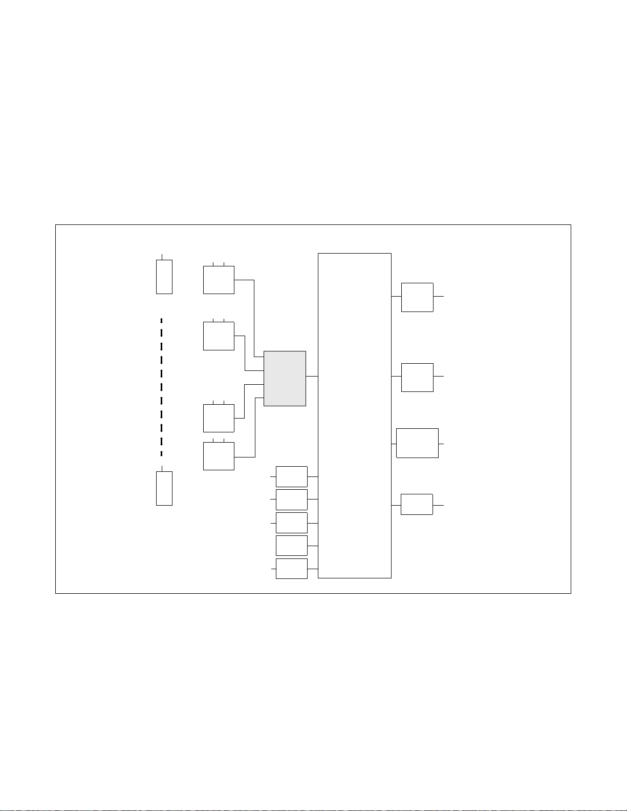
1. GENERAL DESCRIPTION OF SYSTEM
The Built-in PCS Syste m has its CSINT, which interf aces th e ZT with the syste m, mounted in the P ort Interfa ce
Module (PIM). The Control Processor Rack (CPR) exclusively designed for the PCS is necessary in the PBX.
Figure 1-1 shows the entire route connecting diagram of this system.
Module structures of the Built-in PCS System are identical to that of the PBX. For more details, see the
“Installation Design Manual”.
PBX
ZT
CCT
PS
ZT
CCIS
Note 1:
Note 2:
PS
ZT
ZT
term
D
Analog
TEL
MAT
CSINT
Note 1
(
ELC
ELC
LC
CFT
IOC
PRT
)
COT/DTI
Note 2
(
ODT
ISDN
PSTN
)
ACIS
Figure 1-1 Route Conne cting Diagram : Buil t-in PCS System
A maximum of four (4) ZTs can be connected to one CSINT circuit card.
If the receive tone l evel of t he P S i s low, please select -5 dB (GAIN) in the PAD data of the COT Route by
the command ARTD.
ND-70290 (E) CHAPTER 1
Page 1
Revision 3.0
Page 19
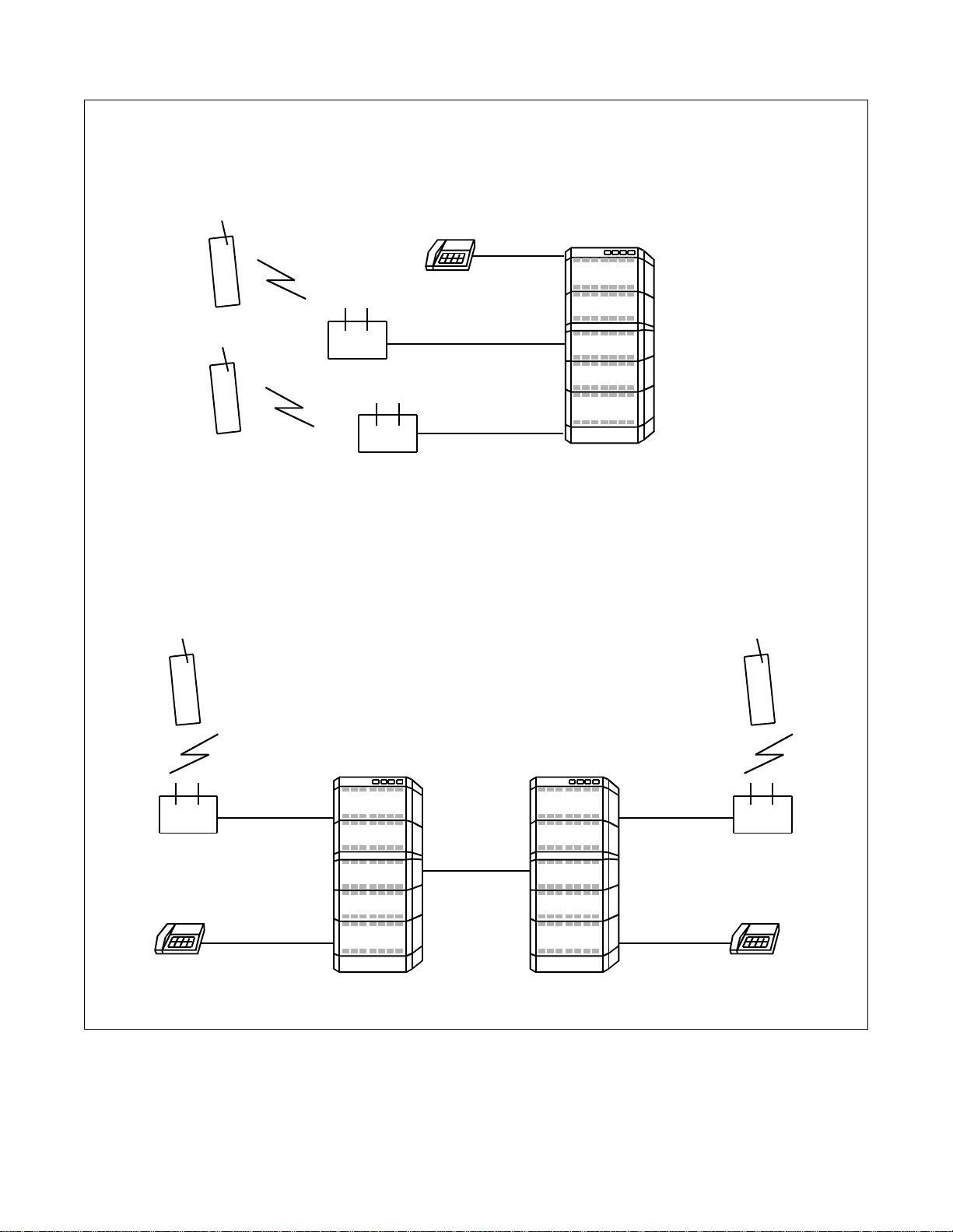
GENERAL DESCRIPTION
Standalone Type
PS
PS
Wireless Term inal
Wired Terminal
ZT
ZT
Built-in PCS System
Fusion Type
Wireless Terminal
PS
ZT
Wired Terminal
NEAX2400
IMX
FCCS
(Fusio n Link)
NEAX2400
IMX
Figure 1-2 Comparison : Standalone Type and Fusion Type
Wireless Terminal
PS
ZT
Wired Terminal
CHAPTER 1 ND-70290 (E)
Page 2
Revision 3.0
Page 20
GENERAL DESCRIPTION
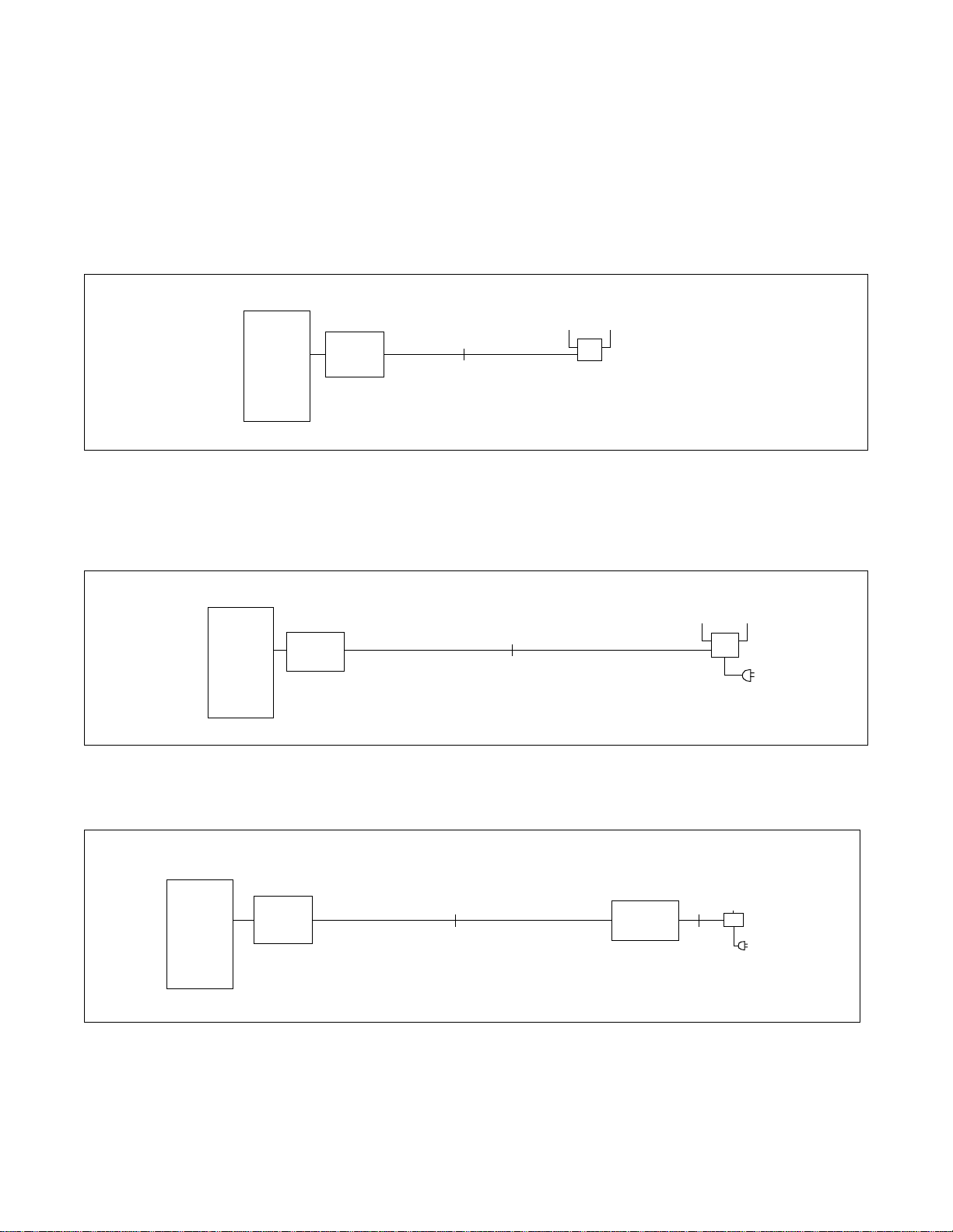
2. CONNECTION B E T WEEN CSINT AND ZT
Figures 1-3 through 1-5 illustrate conne ction methods between the CSINT and the ZT. The CSINT and the ZTs
can be connec ted wit h two pairs of twisted cable using the foll owing two conne ction method s - on e, line voltage
from the Built-in PCS System and the other, the local power supply.
1. PBX line power from Built-in PCS System.
Line Power from the PCS System is powe r to the ZT suppli ed from the PBX.
PBX
CSINT
(PA-4CSIC
/PA-4CSIE)
S interface
Figure 1-3 Power Supply from the Built-in PCS System
2. Local Power Supply
Local power for th e ZT is supplied via AC-DC adapter from the AC.
PBX
CSINT
(PA-4CSIC
/PA-4CSIE)
Figure 1-4 Local Power Supply
S interface
ZT
ZT
3. U Interface (NT1 is used)
PBX
CSINT
(PA-4CSID
/PA-4CSIF)
Figure 1-5 Route Connection Diagram : U Interface (When NT1 is used)
U Interface
NT1
S Interface
ZT
ND-70290 (E) CHAPTER 1
Page 3
Revision 3.0
Page 21

GENERAL DESCRIPTION
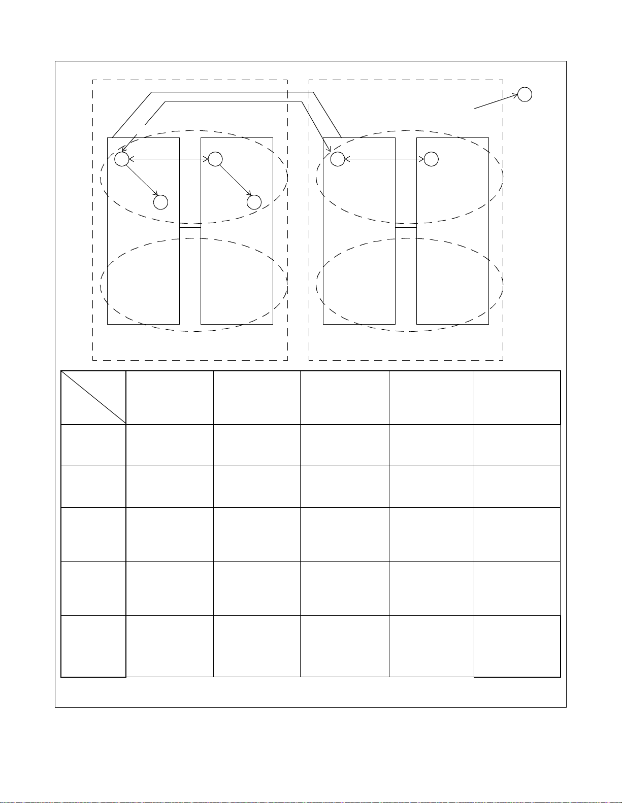
3. MOVEM ENT OF PS IN NEAX2400 IMX
PCS COMMUNITY
The SYS-ID is a unique ID which was given to manage the PCS system. The area where the SYS-ID is effective
is called PCS Community. Every PCS Community in a Fusion network is given a unique PHS Community
Number (PCN). Each PCN has its own SYS-ID. The PCN is used in stead of the SYS-ID for MAT command,
and this can reduce the effect upon changing the SYS-ID to some measure. The habitual operation of the
SYS-ID, w hich re aches to nine dig its for t he man agem ent purpos e, is not nee ded; therefore easy maintenance
can be provided. A single PCS Community can be assigned in multiple nodes, and a single node can belong to
multiple PCS Communities by using the Tenant service.
PS movement in the system is classified into three kinds as described below:
1. Stand-by condition movement
Movement of an idle PS within the home PCN area in the home Fusion network (in the Fusion network
accommodating the home node). The event of PS Location Registration occurs only when the PS moves
over t he Calling area . Eve n if a PS is in Roaming st atus, mov ement of the PS within the cur rent vi sitor node
is also stand-by condition move ment. In the syste m, the home PCN can be assigned over the node, however
the Calling Area cannot. Because of this, the event of PS Loc ation Registration occurs whenever an idle PS
moves over the node.
2. Hand-Over
Movement of a PS engaged in communication within the home PCN area in the home Fusion network. The
event of Hand-Over occurs regardless of the Calling Area.
Even if a PS is in the Roaming status, movement of the PS engaged in communication within the current
visitor node is also Hand-Over. In the system, the call engaged in communication is supported even in th e
case of Hand-Over over the node.
3. Roaming
PS Location Registra tion to the ZT in another PCN than the home PCN is called Roaming. The cal l engaged
in communication is not supported.
CHAPTER 1 ND-70290 (E)
Page 4
Revision 3.0
Page 22
GENERAL DESCRIPTION
Home
A
Node-W
Fusion-I
Home PCN-a
B
FCCS
Q. 931a or IS-11572 Note
C
D
PCN-b
Node-X
Fusion-II
Visit PCN-c
Visit
E F
FCCS
Node-Y
PCN-d
G
Node-Z
Move to
Move from
A, B
Home Node
Home PCN
C, D
Visit Node
Home PCN
E
Visit Fusion
Visit Node
Visit PCN
F
Visit Fusion
Other Node
Visit PCN
G
Yet Other
Fusion
A, B
Home Node
Home PCN
Stand-by condition
Movement
H-O
Stand-by condition
Movement
H-O
C, D
Visit Node
Home PCN
Stand-by condition
Movement
H-O
Stand-by condition
Movement
H-O
Roaming Cannot move Cannot move
Cannot move Cannot move Cannot move
E
Visit Fusion
Visit Node
Visit PCN
Roaming Cannot move Stand-by condition
Movement
H-O
Cannot move Cannot move Stand-by condition
Movement
H-O
Stand-by condition
Movement
H-O
Stand-by condition
Movement
H-O
F
Visit Fusion
Other Node
Visit PCN
G
Yet Other
Fusion
Cannot move
Cannot move
Cannot move Cannot move Cannot move Cannot move Roaming or Stand-
by condition
Movement
(depending on the
case)
Note:
Node-W and Node-Y are connected with Q. 931a or IS-11572.
ND-70290 (E) CHAPTER 1
Page 5
Revision 3.0
Page 23

GENERAL DESCRIPTION
4. SYSTEM CAPACITY
The following explains the capacity of the System.
Table 1-1 System Capacity
ITEMS 1-IMG System 4-IMG System
IMX-U System
Max. number of PSs/Node 1500 terminals
or
4000
terminals (optional)
Note 1
4000
terminals
Note 1
16000
terminals
Max. number of ZTs 192 768 3072
Max. number of CSINTs 48
Max. number of PHS Community Number
(PCN)/system
Note 2
192
Note 2
1024
768
Note 2
Spe e ch C H/ZT 3 ch/ZT
Max. number of ZTs/CSINT 4
Max. number of calling areas/PCN 32 areas
Area
Max. number of ZTs/calling area 192 ZTs/area 256 ZTs/area
Max. number of groups/calling area 8 groups/area (Not used)
Note 1:
Depending on capacity of NDM/LDM.
When upgrading from ICS and re-using Data Memory, Maximum 2000 terminals/Node.
Note 1
Note 2:
A maximum of 12 circuit cards can be mounted in a PIM.
5. MO UNTING LOCATION OF CSINT CIRCUIT CARD
CSINT circuit card can be mounted in any universal slot in the PIM.
CHAPTER 1 ND-70290 (E)
Page 6
Revision 3.0
Page 24

6. FUNCTIONS/MOUNTING CONDITIONS OF CIRCUIT CARDS
The following circuit cards are necessary when using the system.
1. Universal LC/TRK circuit cards
GENERAL DESCRIPTION
ABBREVIATION
CIRCUIT
CARD NAME
RST PA -8RSTJ/
PA-8RST M
DA T PA-4DATA/
PA-4DATB
TSW PH-SW10
(1-IMG
System)
OSC PA-CK14
(1-IMG
System)
PLO PH-CK16/
PH-CK16-A
(Other than
1-IMG
System)
PH-CK17/
PH-CK16-A
(Other than
1-IMG
System)
FUNCTIONS AND MOUNTING CONDITIONS
Register-Sender
As is the case with the R ST functi ons i n the nor mal sta tions, t he RST is use d
virtuall y, and estimati n g h ow many li n es are needed is as im portant as
considering the number of terminals.
Refer to the “Circuit Card Manual” for SW setting.
Announcement Trunk
Used for ANNOUNCEMENT-PS OUT OF ZONE.
Refer to the “Circuit Card Manual” for SW setting.
Synchronized with the digital circuit cards such as PRT/DTI in a variety of
combinations. (Standard precision clock oscillator) This card is
synchronized with clocks generated from the PRT/DTI, thus supplying the
necessary clock signal to the system.
Number of clock input route: DTI: 4, DCS: 2
Functions: Burst Cyclic Generator of 5ms which suppl ies clock signal ing
to ZT.
Refer to the “Circuit Card Manual” for SW setting and wiring.
Synchronized with the digital circuit cards such as PRT/DTI in a variety of
combinations. (High precision clock oscillator) This is synchronized with
clocks generated from the PRT/DTI, thus supplying the necessary clock
signal to the system.
Number of clock input route: DTI: 4, DCS: 2
Functions: Burst Cyclic Generator of 5ms which suppl ies clock signal ing
to ZT.
Refer to the “Circuit Card Manual” for SW setting.
ND-70290 (E) CHAPTER 1
Page 7
Revision 3.0
Page 25

GENERAL DESCRIPTION
ABBREVIATION
CIRCUIT
CARD NAME
CLK PH-CK18
(IMX-U
System)
This card is used for the Local Node of the IMX-U system. This card receives
clock signals from the Phase Lock Oscillator (PLO) accommodated in
TSWM0 of IMG1, distributing the following signals to Time Division
FUNCTIONS AND MOUNTING CONDITIONS
Switch (TSW) accommodated in TSWM1 of IMG2.
• 32.768 MHz CLK
• 8 KHz FH
•5 msec × “n” FH
CSINT P A-4CSIC This is an LC circuit card which provides inter face with the Zone Transc eive r
(ZT). A maximum of four ZTs can be connec ted to one ci rcuit card. Interface
of the ZT corresponds to ISDN standards, but multi-point connection with
the ZTs is not available.
• I.430, Q. 921 in terface
• B channel is used for two channels of 32 kbps each with a t otal speed of
64 kbps in the 2B+D.
P A-4CSID This is an LC circuit card which provides interface with the Zone Transcei ver
(ZT). A maximum of four ZTs can be accommodated to one circuit card.
NT1 is used in connecting the ZTs. Interface with NT1 corresponds to U
Reference point of ISDN standards of the Echo canceller method.
• ANSI T1.601 interface is used
• B channel is used for two channels, each with a transmissio n speed of 32
kbps, with a total of 64 kbps. (2B+D)
• Functions as a Sealing Currency supplier to the NT1
(Maximum 15 mA to protect cables from rusting)
P A-4CSIE This is an LC circuit car d which provides interf ace with the Zone Transcei ver
(ZT). A maximum of four ZTs can be connec ted to one ci rcuit card. Interface
of the ZT corresponds to ISDN standards, but multi-point connection with
the ZTs is not available.
• I.430, Q. 921 in terface
• B channel is used for two channels of 32 kbps each with a t otal speed of
64 kbps in the 2B+D.
P A-4CSIF This is an LC circuit card which provides inter face with the Zone Transc eive r
(ZT). A maximum of four ZTs can be connec ted to one ci rcuit card. Interface
with NT1 corresponds to U Reference point of ISDN standards of the Echo
canceller method.
• ANSI T1.601 interface is used
• B channel is used for two c hannels of 32 kbps each with a total of 64 kbps
in the 2B+D.
• Functions as a Sealing Currency supplier to the NT1
(Maximum 15 mA to protect cables from rusting)
CFT PA-CFTB 8-Party Conference Trunk
Used SP388 (firmware) for G ROUP CALL- AUTOMATIC CONFERENCE
Used SP1141 (firmware) for GROUP CALL-AUTOMATIC
CONFERENCE (20-party).
Refer to the “Circuit Card Manual” for SW setting.
CHAPTER 1 ND-70290 (E)
Page 8
Revision 3.0
Page 26

7. SERVICE CONDITIONS
Below are some of the conditi ons for usin g the System.
1. The system is available in the Business/Hotel System.
2. ACD/OAI services are incompatible with the system.
3. The following software is necessary for system operation.
Basic software: Series 7300 or later
GENERAL DESCRIPTION
Optional software: Service (Application) software including PCS service.
Note:
When using P CS in F us ion Network , th i s software must be installed i n all nodes. Even i f no PSs are accommodated in a node, this software must be installed in the node.
4. SMDR equipment can be used for billing.
5. The following billing services are available in the system.
FEATURE NAME REMARKS
SMDR for outgoing C.O. line
SMDR for incoming C.O. line
SMDR for outgoing Tie line
SMDR for incoming Tie line
SMDR for incoming DID
SMDR for DIT
SMDR for IC via ATT-CON
6. PS is not connected to the data terminal equipment.
7. PS station number cannot be programmed on the feature key of D
Note
term
(as a Multi-Line).
8. SID TO TERMINATING USER-DISPLAY/ANALOG CALLER ID service features are not available for
PS.
9. Service conditions for CCIS features are as follows:
(a) When a call is originated from or terminated to a PS via CCIS, the calling number sent to the called
station varie s dep en d i n g on t h e num b eri n g p lan as shown below.
Closed numbering network: Station number (PS number)
Open numbering network: Office code + Station number (PS number)
(b) When a PS user has a call placed on hold, link re-connect ion i s no t performe d .
ND-70290 (E) CHAPTER 1
Page 9
Revision 3.0
Page 27

GENERAL DESCRIPTION
8. LIST OF SERVICE FEATURES
1. PCS Feature
Table 1-2 List of PCS Features
SERVICE FUNCTIONS REMARKS
UNUSED NUMBER
PS LOCATION
REGISTRATION
OG CALL TO OUTSIDE Least Cost Routing (LCR) is the only dialing method valid in OG call to
outside.
Note 1:
For Fusion Network, this feature is available for Release 3 or
later software.
INDIVIDUAL PS CALLING Incoming calls can be terminated to a PS only in the area where the
corresponding PS is registered.
CALL WAITIN G
CALL HOLD
CALL TRANSFER
CALLING ZT ZONE
A maximum of 32 areas can be assigned in each PCN.
REGISTRATION
Note 2:
One Fusion Link Network can have PCN 1 ~ 1024.
DISTINCTIVE RINGING
PB (DTMF) SIGNAL SENDER
PS-TO-STATION CALL
PS AUTHENTICATION
HANDOVER
Note 3
PRESET DIALING A maximum of 24 digits can be used when dialing. The buttons that can
be used are: 0-9, # and *.
OVERLAP DIALING A maximum of 24 digits can be used when dialing. The buttons that can
be used are: 0-9, # and *.
PS SERV ICE CLASS RSC and SFC for a PS i s the sa me as t hose for a single line tele phone and
term
.
D
AUT OMATIC ANNOUNCEMENT-
DISCONNECTED PS OUT OF
ZONE
C.F.-PS INCOMING
INCOMPLETE
AUT OMA TIC ANNOUNCEMENT PS OUT OF ZONE
CHAPTER 1 ND-70290 (E)
Page 10
Revision 3.0
Page 28

GENERAL DESCRIPTION
Note 3:
Handover
1) If a PS user moves to another zone that has all speech channels busy, the PS remains connected to the
original ZT.
2) Speech i s t em p o rar ily inte rru p t ed d u r ing handover.
3) PS is unable to hand over in the following ca ses:
• When digits are being sent (BT is heard.)
• When a PS user attempts to hand over while connected to an operator (Attendant Con s ole). BT is
heard.
• When user C who has set Call Waiting to user A attempts to hand over while users A and B are
talking. For deta il s , se e th e follo wing ta ble.
STATUS
PS TERMINAL A PS TERMINAL B PS TERMINAL C
HANDOVER TERMINAL
PS terminal A Call Waiting Tone
Released (BT) Ring Back Tone (RBT)
(CWT)
PS terminal B Talking with PS C Released (BT) Talking with PS A
PS terminal C Talking with PS B Talking with PS A Released (BT)
• When a PS user is calling.
4) When using Fusion Link Network, PS can hand-over to another node as long as the destination node
uses the same PCN.
2. PBX functions are available in the Built-in PCS System.
Tables 1-3 through 1-11 show functions available in the Built-in PCS System. Some of the following
functions not available in this system are:
term
•D
function
• OAI-ACD functions
• OAI functions
• Data functions
ND-70290 (E) CHAPTER 1
Page 11
Revision 3.0
Page 29

GENERAL DESCRIPTION
NAME OF SERVICE FEATUR ES
Table 1-3 List of OG Call Features
×: Available : Conditionally available –: Not available/Not used
Standalone Fusion
REMARKS
From PS To PS From PS To PS
ALTERNATE ROUTING/ROUTE
ADVANCE
SPEED CALLING-STATION/
GROUP
× –––
––––
T o be substitut ed for the memory
dial of PS
SPEED CALLING-SYSTEM – – – –
TOLL CALL RE S T RI CT ION × –––
PUSH-BUTTON TO ROTARY
CONVERSION
––––
PRIMARY CODE RESTRICTION × –––
OG TRUNK QUEUING – – – –
OFF HOOK QUEUING – – – –
MISCELLANEOUS TRUNK
RESTRICTION/ RESTRICTION
× –––
FROM OG CALL
Table 1-4 List of IC Call Features
×: Available : Conditionally available –: Not available/Not used
Standalone Fusion
NAME OF SERVICE FEATURES
From PS To PS From PS To PS
REMARKS
EXTERNAL MUSIC-ON-HOLD ––––
ATTENDANT CONSOLE ××××
DIT – × – ×
SLUMBER TIME - DO NOT
DISTURB
POW ER FAILURE TRANSFE R
DISTINCTIVE RINGING
REMOTE ACCESS TO SYSTEM/
AUTOMATED ATTENDANT
––––
––––
– × – ×
– × – ×
TENANT SERVICE ××––
MUSIC-ON-HOLD ××××
CHAPTER 1 ND-70290 (E)
Page 12
Revision 3.0
Note 1
PS cannot be used for the Night
station
term
Avail able in the D
term
D
Note 3
PSII
Note 2
PS or
Page 30

GENERAL DESCRIPTION
Note 1:
Note 2:
When a PS is assigned as the target station of DIRECT IN TERMINATION (DIT).
1) When the PS is Out of Zone (Out of Zone or in a state of POWER OFF), RBT is heard by the calling
party.
If AUTOMATIC ANNOUNCEMENT-PS OUT OF ZONE is assigned by the PS, the calling party does
not hear the Out of Zone Announcement, and instead hears RBT.
2) If a PS user moves Out of Zone w hile co nnected to an outside party, AUTOM AT IC ANNOUNCEMENTDISCONNECTED PS OUT OF ZONE cannot be heard by the outside party, but instead BT is heard.
3) When a PS is engaged and an outside call attempts CALL WAITING, the caller will hear RBT.
4) When a DIT call is transferred to a PS or a station that has set C.F.-PS INCOMING INCOMPLETE,
the calling party hears RBT if the target PS or station is Out of Zone or in the state of lock-out.
5) PS is unable to hand over when it is ringing. When the PS hands over, the called PS stops ringing, and
the calling party hears RBT.
6) In Fusion Network, PS must be called with Physical Station Number.
A call from an incoming Tie Line gives the same ringing as a station call.
Note 3:
Remote Access to System/Automated Attendant: Terminating side is PS.
1) When the PS is Out of Z one (Out of Ar e a or in a state of PO WER OFF), the callin g party w will hear BT.
If the AUTOMATIC ANNOUNCEMENT-PS OUT OF ZONE is set by the PS, the calling party does not
hear Out of Zone Announcement. The calling party hears BT.
2) If a PS user moves Out of Zone while connected to an outside line, AUTOMATIC ANNOUNCEMENTDISCONNECTED PS OUT OF ZONE cannot be heard by the subscriber outside. BT is heard.
3) When a REMOTE ACCESS TO SYSTEM/AUTOMATED ATTENDANT call is transferred to a PS or a
station with C.F.-INCOMING INCOMPLETE set and when the transferred party is Out of Zone or in
the state of lock-out, the calling pa rty hears RBT.
4) PS is not allowed to hand over while ringing. Whe n the called PS is ringing fr om the REMO TE ACCESS
TO SYSTEM/AUTOMATED ATTENDANT and the PS hands over, the PS stops ringing and the calling
party hears RBT.
ND-70290 (E) CHAPTER 1
Page 13
Revision 3.0
Page 31

GENERAL DESCRIPTION
Table 1-5 List of Station Service Features
×: Available : Conditionally available –: Not available/Not used
Standalone Fusion
NAME OF SERVICE FEATURES
From PS To PS From PS To PS
OFF HOOK ALARM ––––
8-PARTY CONFERENCE ––––
REMARKS
C.F.-A-OUTSIDE ××××
Note 1
C.F.-D-OUTSIDE ××××
C.F.-B-OUTSIDE ××××
C.F.-A ××××
C.F.-A CANCEL BY A ROUTINE
DIAGNOSIS
––––
CALL TRANSFER - ALL CALLS ××××
Note 6
Note 2
EMERGENCY CALL ––––
DAY/NIGHT CLASS OF SERVICE––––
CALL WAITIN G ××××
CALL PICK UP - GROUP
××––
Note 3
Not available to do “Pick Up”
from another node
CALL HOLD ––––
THREE-WAY CALLING ××××
TIMED REMINDER ––––
CALL PICK UP - DIRECT
× –––
Not available to do “Pick Up”
from another node
STEP CALL ××××
Note 4
SPLIT C.F. ––––
HOT LINE ××––
PERIODICAL INDICATI ON TONE × –––
AUT OMATIC CALL BACK
CANCEL
––––
CLASS OF SERVICE - INDIVIDUAL ××××
STATION-TO-STATION CALLING ××××
STATION-TO-STATION CALL
RESTRICTION
××××
EXECUTIVE RIGHT OF WAY ––––
STATION HUNTING ––––
CALL BACK ––––
CHAPTER 1 ND-70290 (E)
Page 14
Revision 3.0
Page 32

Table 1-5 List of Station Service F e a t ures (Continued)
NAME OF SERVICE FEATURES
GENERAL DESCRIPTION
×: Available : Conditionally available –: Not available/Not used
Standalone Fusion
REMARKS
From PS To PS From PS To PS
FLEXIBLE NUMBERING OF
STATION
AUT OMATIC HOWLER TONE
SENDING
××××
––––
STATION 5 DB PAD ××××
BOSS/SECRETARY ––––
C.F.-D ××××
Note 6
PUSH-BUTTON CALLING ––––
PRIORITY CALL × – × –
Note 5
LINE LOCK-OUT ––––
RECALL × – × –
C.F.-B ××××
Note 6
PRIVACY ––––
ONE DIGIT HOOKING ––––
Note 1:
Note 2:
C.F.-D-Outside is not applicable by way of CALL TRANSFER-ALL CALLS.
Recall service can be activated to the transferred station when the PS, with C.F.-PS INCOMING CALL
INCOMPLETE in service, moves Out of Zone, after placing a call on hold.
Note 3:
Note 4:
Note 5:
Note 6:
Call Waiting
1) This service is valid in the two party call when a call is terminated – from station-to-station, to PS, to
Central Office line, or to Tie line call – but invalid when other services using switch hook flash are
executed to the PS or when the PS is connect ed t o t he A tte ndant Console.
2) To set CALL WAITING, it is necessary that the Service Restriction Class data (ASFC) be assigned in
the office data assignment.
Call Waiting service is provided according to each service feature restrict i on cl a ss.
3) There is no limitation of the number of CALL WAITING services such as the number of simultaneous
settings/the number of occurrence of answers.
4) This service cannot be used if the Central Office line (DIRECT IN TERMINATION) or a call via the
Attendant Console.
Tie line STEP CALL is not available from PS.
PS can activate this feature only for Attendant Console.
In the Fusion network, the destination of call forwarding from PS must have a Telephone Number.
ND-70290 (E) CHAPTER 1
Page 15
Revision 3.0
Page 33

GENERAL DESCRIPTION
Table 1-6 List of Other Service Features
×: Available : Conditionally available –: Not available/Not used
Standalone Fusion
NAME OF SERVICE FEATUR ES
From PS To PS From PS To PS
AUTHORIZATION CODE ––––
ACCOUNT CODE ––––
REMARKS
C.F.-INTERCEPT/
ANNOUNCEMENT
× –––
CALL PARK ––––
DISTRIBUTION ACCESS UNIT
(DAU)
––––
DSS CONSOLE ––––
ANNOUNCEMENT SERVICE × –––
OG CALL RESTRICTION
ANNOUNCEMENT
× –––
PAGING ––––
PAGING TRANSFER ––––
RADIO PAGING ––––
UNIFORM CALL DISTRIBUTION
(UCD)
––––
UCD-DELAY ANNOUNCEMENT ––––
LAST NUMBER CALL
––––
Substituted for the LAST
NUMBER CALL function of PS
CHAPTER 1 ND-70290 (E)
Page 16
Revision 3.0
Page 34

Table 1-7 List of Attendant Console Service Features
×: Available : Conditionally available –: Not available/Not used
Standalone Fusion
NAME OF SERVICE FEATUR ES
From PS To PS From PS To PS
AU TOMATIC RECALL – × – ×
ATTENDANT LOOP RELEASE – – – –
GENERAL DESCRIPTION
REMARKS
CALL TRANSFER-ATTENDANT – × – ×
Note 1
SUPERVISORY CALL – × – ×
DIGITAL DISPLAY-TRUNK – – – –
CALL PROCESSING INDICATION ××××
SERIAL CALL ––––
CALL WAITING LAMP DISPLAY × – × –
ATTENDANT CAMP-ON – – – –
NON-DELAY OPERATION × – × –
Note 3
INTER-POSITION TRANSFER – – – –
DELAY OPERATION × – × –
Note 3
DIAL MONITOR – × – ×
SPLIT CALL FORWARDING – – – –
TRUNK GROUP BUSY LAMP – – – –
SPEED CALLING-STATION/
GROUP
––––
SPEED CALLING-SYSTEM – – – –
INDIVIDUAL ATTENDANT
ACCESS
× – × –
ATTENDANT OVERRIDE – – – –
STEP CALL – × – ×
ATTENDANT MONITOR
SERVICE
––––
ATTENDANT NIGHT TRANSFER × –––
BUSY VERIFICATION – – – –
IND IV IDUAL TRUNK ACCE SS – – – –
DIAL ACCESS TO ATTENDANT ××××
DIGITAL DISPLAY-STATION ××××
Note 2, Note 3
Note 3
BUSY LAMP FIELD-FLEXIBLE ××––
RECALL × – × –
ND-70290 (E) CHAPTER 1
Page 17
Revision 3.0
Page 35

GENERAL DESCRIPTION
Note 1:
Note 2:
Note 3:
Upon receiving an incoming call, the Attendant C on s ole transfers the call to a PS, then it ends up with the
PS connected to the outside.
If, in this situation, the PS user moves to a place Out of Zone, the caller from the outside line will hear BT.
While the Attendant Console is calling a PS, the services associated with Out of Zone such as C.F.-PS
INCOMING INCOMPLETE, AUTOMATIC ANNOUNCEMENT-PS OUT OF ZONE and AUTOMATIC
ANNOUNCEMENT-DISCONNECTED PS OUT OF ZONE are not available.
When an Attendant calls a PS, the individual attendant number can be displayed on the LCD of the PS.
However “OPR ” cannot be displayed on the LCD of the PS.
This service Feature has the limitation of Fusion Link Network. Refer to the Fusion Network System
Manual/Feature Programming Manual.
CHAPTER 1 ND-70290 (E)
Page 18
Revision 3.0
Page 36

Table 1-8 List of Network Service Features
NAME OF SERVICE FEATURES
GENERAL DESCRIPTION
×: Available : Conditionally available –: Not available/Not used
Standalone Fusion
From
PS
To PS From PS To PS
REMARKS
AU TOMATIC CIRCUIT
ASSURANCE
× – × –
CENTREX COMPATIBILITY – × – ×
DELUXE TRAVEL CLASS MARK – – – –
LCR - AUTOMATIC OVERFLOW × – × –
LCR-3/6-DIGIT × – × –
Note 1
TANDEM CONNECTION – – – –
TANDEM TRUNK QUEUING – – – –
TANDEM PAD CONTROL – – – –
TIE LINE ACCESS ××××
OUTGOING TRUNK BUSY -
ANNOUNCEMENT
× –––
HOT LINE - OUTSIDE × –––
DIGITAL TRUNK INTERFACE ××× ×
LCR - SPECIAL LINE WARNING × –––
UNIFORM NUMBERING PLAN ××× ×
LCR - TIME OF DAY ROUTING – – – –
LCR - CLOCKED MANUAL
OVERRIDE
ATTENDANT MANUAL
OVERRIDE
––– –
––– –
Table 1-9 List of Operation/Maintenance Service Features
×: Available : Conditionally available –: Not available/Not used
Standalone Fusion
NAME OF SERVICE FEATURES
From PS To PS From PS T o PS
SERVICE PEG COUNT × –––
TRAFFIC MEASUREMENT ××––
INDIVIDUAL TRUNK ACCESS – – – –
LINE LOAD CONTROL – – – –
Note 1:
This service feature has the limitation for the Fusion Link Network. Refer to the Fusion Network System
Manual.
ND-70290 (E) CHAPTER 1
REMARKS
Page 19
Revision 3.0
Page 37

NAME OF SERVICE FEATUR ES
Table 1-10 List of ISDN Service Features
×: Available : Conditionally available –: Not available/Not used
Standalone Fusion
From PS To PS
From
PS
To PS
REMARKS
DIRECT INWARD DIALING – × – ×
SUB ADDRESS - PRESENT × –––
SUB ADDRESS - ADDRESSING – × – ×
CALLING PARTY NUMBER -
PRESENT
CALLING PARTY NUMBER -
DISPLAY
Note 1:
Automatic Announcement - PS Out of Zone/C.F. PS Incoming Incomplete may not be available. It depends
× –––
– × – ×
on Public ISDN Network.
Note 2:
The ISDN terminal cannot transfer the call to a PS or provide the 3-party conference feature including a
PS.
Note 3:
A PS can transfer the call to ISDN terminal and p r ov ide the 3-party confe renc e featu r e including the ISDN
terminal.
Note 1
Note 1
CHAPTER 1 ND-70290 (E)
Page 20
Revision 3.0
Page 38

GENERAL DESCRIPTION
Table 1-11 List of CCIS Features
×: Available : Conditionally available –: Not available/Not used
NAME OF SERVICE FEATURES
Attendant Controlled Conference CCIS
ORIGINATED
FROM P S
– ×
TERMINATED
TO PS
Automatic Recall - CCIS × –
Brok erage Ho tline - CCIS – ×
Call Forwarding - All Calls - CCIS ××
Call Forwarding - Busy Line - CCIS ××
Call Forw ard i n g - Do n’t A n s w er -
CCIS
××
Call Transfer - All Calls - CCIS ××
Calling/Called Number Display -
CCIS
××
Consultation Hold - All Calls - CCIS ××
Deluxe Traveling Class Mark - CCIS ××
Dial Access to Attendant - CCIS × –
Digital Display - Station - CCIS × –
REMARKS
Direct In Terminati o n - CC IS – ×
Distinctive Ringing - CCIS – ×
Do not Disturb - CCIS – ×
Dial Number Display - Recall - CCIS ××
Flexible Numbering of Statio n - CCIS × –
House Phone - CCIS – ×
Hot Line - CCIS ××
Incoming Call Identification - CCIS × –
Indiv idua l A t tenda nt Access - CC I S × –
LDN Night Connection - CCIS – ×
Miscellaneous Trunk Access - CCIS × –
Miscellaneous Trunk Restriction -
CCIS
Multiple Call Forwarding - All Calls -
CCIS
Multiple Call Forwarding - Busy Line
- CCIS
× –
××
××
ND-70290 (E) CHAPTER 1
Page 21
Revision 3.0
Page 39

GENERAL DESCRIPTION
Table 1-11 List of CCIS Features (Continue d)
×: Available : Conditionally available –: Not available/Not used
NAME OF SERVICE FEATURES
Multiple Call Forwarding - Don’t
Answer - CCIS
ORIGINATED
FROM P S
××
TERMINATED
TO PS
Night Connection - Fixed - CCIS – ×
Night Connection - Flexible - CCIS – ×
Off-Hook Queuing - CCIS × –
Single Digit Station Calling - CCIS × –
Station Controlled Conference - CCIS – ×
Step C al l - CC IS – ×
Supervisory Call - CCIS – ×
REMARKS
CHAPTER 1 ND-70290 (E)
Page 22
Revision 3.0
Page 40

CHAPTER 2 INSTALLATION DESIGN
This chapter describes the installation for the Built-in PCS system.
1. INSTALLATION
This section explains how to connect the Built-in PCS system and its related equipment. Refer to the
“Installati on Manual” to learn the insta llation method of the PBX and its related equipment that is included here.
• ZT (Zone Transceiver) : Connection with S interface
• ZT (Zone Transceiver) : Connection with U interface
1.1 ZT (ZONE TRANSCEIVER) AND ITS CONNECTION WITH S INTERFACE
1. General
This part explains how to connect the Zone Transceiver (ZT).
2. Circuit Card
NAME OF CIRCUIT CARD 2W/4W REMARKS
PA-4CSIC 4W
PA-4CSIE 4W
ND-70290 (E) CHAPTER 2
Page 23
Revision 3.0
Page 41

INSTALLATION DESIGN
3. Cable Connection
a. When using PA-4CSIC
ATTENTION
Contents
Static Sensitive
Handling
Precautio ns Requ ir ed
PIM
Back-
LT
board
RB0
26
TB0
27
No.0
No.1
No.2
No.3
RB1
28
TB1
29
RB2
30
TB2
31
RB3
32
33
TB3
34
35
36
37
38
39
40
41
42
43
44
45
46
47
48
49
50
CSINT (LT cable) Champ connector lead
10
11
12
13
14
15
16
17
18
19
20
21
22
23
24
25
P
RA0
1
2
TA0
RA1
3
4
TA1
5
RA2
TA2
6
7
RA3
8
TA3
9
Installa tio n ca bl e
(SWVP50 lead)
MDF
Note 1
(
TB
RB
RA
TA
No.0
No.1
No.3
)
MDF
TB
RB
Note:
Confirm that the electric potential be-
ZT
TA
RA
Modular
rosette
(eg. RJ-45)
Modular plug
ZT
tween TA/TB and RA/RB (feed polarity) is normal before connecting ZT to
modular rosette.
TA/TB minus
RA/RB plus
Figure 2-1 Related Equipment for Built-in PCS System (When using PA-4CSIC)
CHAPTER 2 ND-70290 (E)
Page 24
Revision 3.0
Page 42

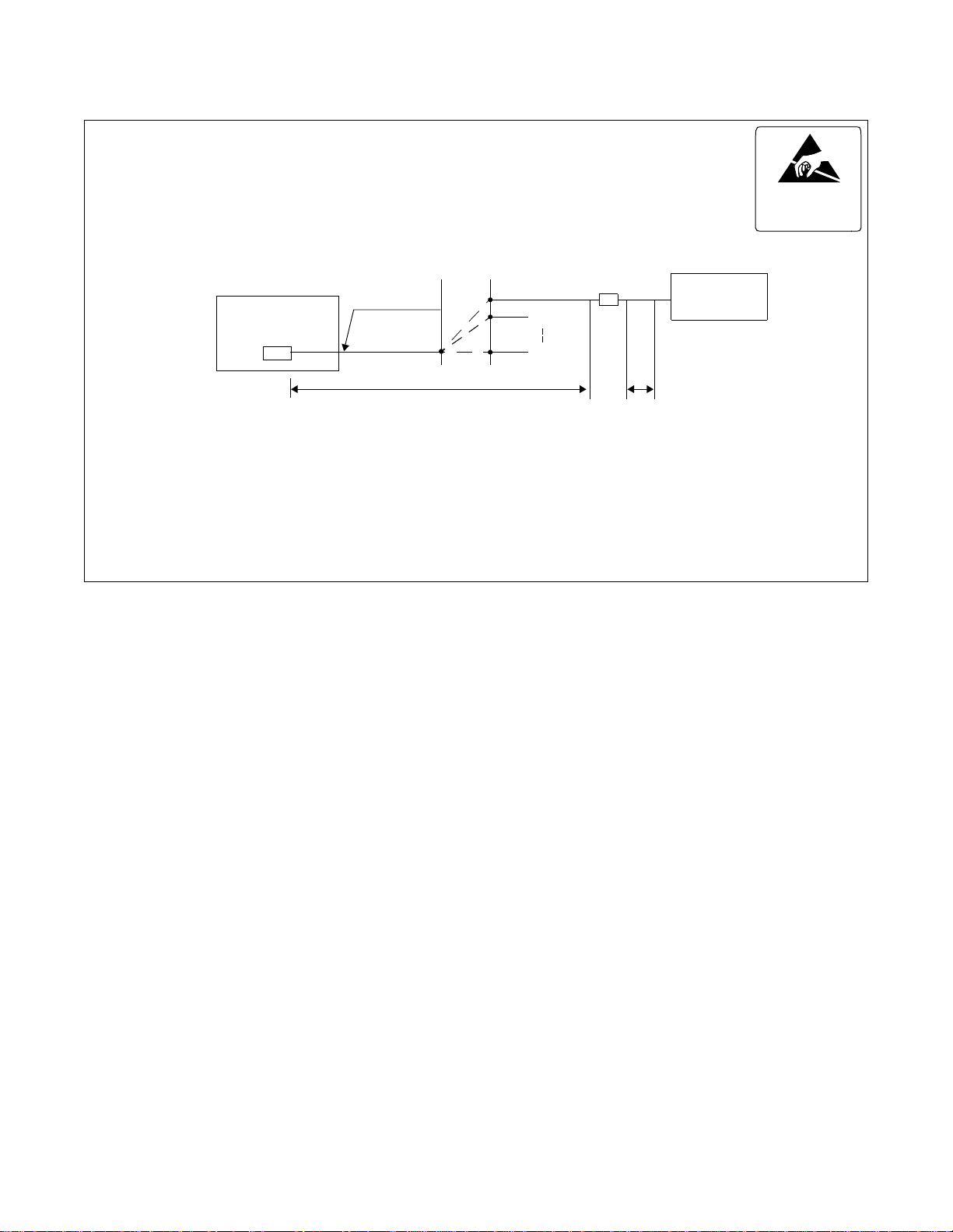
INSTALLATION DESIGN
Note 1:
Maximum length of the cable to each ZT depends on the kind of cable (diameter) and the way of power
supply (Power supply from Built-in PCS system/Local power supply).
Power supply from Built-in PCS system (Without arrestor, when feed output is 48V)
Diameter
Distance
(No arrestor)
26 AWG 24 AW G 22 AWG 19 AWG
762 m 1219 m 1676 m 2438 m
2500 ft 4000 ft 5500 ft 8000 ft
Local power supply
26 AWG 24 AW G 22 AWG 19 AWG
1189 m 1341 m 1676 m 2438 m
3900 ft 4400 ft 5500 ft 8000 ft
(No arrestor)
Note 2:
Diameter
Distance
Connection of the connector lead depen ds on the mounting location of CSINT circ uit card . For mor e detail ,
refer to Chapter 3, "Circuit Cards".
Note 3:
Below is the specification of modular plug that is used for the connection to ZT.
• RJ-45 modular plug
TERMINAL
NUMBER
1
2
3
4
5
6
7
8
Terminal
number
TERMINAL
NUMBER
a
b
c
d
e
f
g
h
(8) (1)
TERMINAL
EQUIPMENT
Not used
Not used
Transmission
Reception
Reception
Transmission
Not used
Not used
Side viewFront view
FUNCTION POLARITY
CSINT
CSINT SIGNAL FEED
TERMINAL
Not used
Not used
Reception
Transmission
Transmission
Reception
+
+
-
-
+
+
-
RA
TA
TB
RB
Not used
Not used
ND-70290 (E) CHAPTER 2
Page 25
Revision 3.0
Page 43

INSTALLATION DESIGN
a. When using PA-4CSIE
ATTENTION
Contents
Static Sensitive
Handling
Precautio ns Requ ire d
PIM
LT
No.0
No.1
No.2
No.3
Backboard
RB0
26
TB0
27
RB1
28
29
TB1
RB2
30
TB2
31
32
RB3
33
TB3
34
35
36
37
38
39
40
41
42
43
44
45
46
47
48
49
50
P
1
RA0
2
TA0
3
RA1
4
TA1
5
RA2
6
TA2
7
RA3
8
TA3
9
10
11
12
13
14
15
16
17
18
19
20
21
22
23
24
25
CSINT (LT cable) Champ connector lead
Installation cable
Note 1
(
Note 2
MDF
)
TB
RB
RA
TA
No.0
No.1
No.3
MDF
Note:
ZT
TB
RB
TA
RA
Modular
rosette
(eg. RJ-45)
Modular plug
ZT
Confirm that the electric potential
between TA/TB and RA/RB (feed
polarity) is normal befor e conn ectin g ZT
to modular rosette.
TA/TB minus
RA/RB plus
Figure 2-2 Relat e d Equipment for Bui lt - in PCS System (When usi ng PA-4CSIE)
CHAPTER 2 ND-70290 (E)
Page 26
Revision 3.0
Page 44

INSTALLATION DESIGN
Note 1:
Maximum length of the cable to each ZT depends on the kind of cable (diameter) and the way of power
supply (Power supply from Built-in PCS system/Local power supply).
Power supply from Built-In PCS system (Without arrestor)
Diameter
26 AWG
(0.4
Φ
)
24 AWG
(0.5Φ)
22 AWG
(0.65Φ)
19 AWG
(0.9Φ)
762 m 1219 m 1676 m 2438 m
Distance
2500 ft 4000 ft 5500 ft 8000 ft
Local power supply (Without arrestor)
Diameter
26 AWG
(0.4
Φ
)
24 AWG
(0.5Φ)
22 AWG
(0.65Φ)
19 AWG
(0.9Φ)
1189 m 1341 m 1676 m 2438 m
Distance
3900 ft 4400 ft 5500 ft 8000 ft
Power supply (With arrestor)
Diameter
26 AWG
(0.4
Φ
)
24 AWG
(0.5Φ)
22 AWG
(0.65Φ)
19 AWG
(0.9Φ)
Note 2:
Distance
300 m 500 m 800 m 1300 m
984 ft 1640 ft 2624 ft 4265 ft
Local power supply (With arrestor)
Diameter
26 AWG
(0.4
Φ
)
24 AWG
(0.5Φ)
22 AWG
(0.65Φ)
19 AWG
(0.9Φ)
350 m 600 m 800 m 1300 m
Distance
1148 ft 1968 ft 2624 ft 4265 ft
Connection of the connector lead depen ds on the mounting location of CSINT circ uit card . For mor e detail ,
refer to Chapter 3, "Circuit Cards".
ND-70290 (E) CHAPTER 2
Page 27
Revision 3.0
Page 45

INSTALLATION DESIGN
1.2 ZT (ZONE TRANSCEIVER) AND ITS CONNECTION WITH U INTERFACE
1. General
This part explains how to connect the Zone Transceiver (ZT) when using the NT1.
2. Circuit Card
NAME OF CIRCUIT CARD 2W/4W REMARKS
PA-4CSID 2W
PA-4CSIF 2W
CHAPTER 2 ND-70290 (E)
Page 28
Revision 3.0
Page 46
3. Cable Connection
INSTALLATION DESIGN
ATTENTION
Contents
Static Sensitive
Handling
Precautio ns Requ ir ed
Note 1:
Note 2:
Note 3:
Backboard
PIM
LT
P
Installation cable
(SWVP50 le ad)
MDF
Note 1
(
No.0
No.1
No.3
)
DSU
(
Note 3
ZT
)
Maximum length of the cable to the DSU depends on the kind of cable (diameter) .
Connection of the connector lead depends on the mounting location of CSINT circuit card. For
more detail, refer to Chapter 3, "Circuit Cards".
Maximum length of the cable to each ZT depends on the kind (diameter) of cable.
ND-70290 (E) CHAPTER 2
Page 29
Revision 3.0
Page 47

INSTALLATION DESIGN
1.3 BASIC KNOWLEDGE ON ZT INSTALLATION
1. Hypothetical Range of Radio Zone
When designing the image of a radi o zone pro vided b y a ZT, the radio zone can be dr a wn by u sing a specific
prefixed distance characteristics value. Provided that a ZT is installed on a wall, the hypothetical distance
characteristics range of the radio zone are as follows:
Indoor (General) : Radius of 49 ft (15 m) approximately
Indoor (floor and corridor with unobstructed view):Radius of 65 ft (20 m) approximately
Outdoor: Radius of 164 to 196 ft (50 t o 60 m) app roximate ly
The range sho wn represe nt model v al ues. Adjus tment of the radio zone shoul d be neede d to design th e f inal
drawings as the radio wave fluctuates unpredictably. It is fundamental that each radio zone be assigned to
ensure sufficient overlap as shown below.
Figure 2-3 Standard Installation Image
Figure 2-4 High Traffic Installation Image
CHAPTER 2 ND-70290 (E)
Page 30
Revision 3.0
Page 48

INSTALLATION DESIGN
2. Image of ZT installation
Assuming a ZT is installed in a general office environment, one ZT can rarely cover the entire service area.
So, a general service area is composed of multiple ZTs. The diagrams below show the image of ZT
installation.
a. Single Floor Installation
ZTs are id eally instal le d at right angles or zigzag l i ke spots o n a di ce.
2ZTs 3ZTs 4ZTs 5ZTs
b. Vertical Successive Floor Installation
It would be ideal to insta ll ZTs at zig zag position a lter nately by e v en-number and odd-number floor s so
that transparent radio waves penetrating floors or ceilings are sufficient enough to receive electric field
to be a radio zone and transparent radio wave between floors is sensed.
Figure 2-5 Image of ZT Installation
ND-70290 (E) CHAPTER 2
Page 31
Revision 3.0
Page 49

INSTALLATION DESIGN
3. Radio Wave Propagation
Although radio waves used by the Built-in PCS System employ a digital signal of service frequency of
approximately 1.9 GHz ba nd, type s of radio w a ve s and typ es of propaga tio n in v ol ved wit h basic radio wa ve
propagation are considered to be t he same as other analog radio waves.
• Types of radio waves
a. Direct waves: Radio waves that are propagated
directly and linearly.
FLOOR
b. Reflected waves/
diffracted waves
(indirect w aves):
Radio waves that are propagated
by being reflec ted or diffracted
from an obstacle, such as a wall
and ceiling.
c. Transm i tted waves: Radio waves that trave l th rough a
wall, floor, partition, etc.
d. Propagating corridor
waves:
Radio waves that trave l along a
corridor. (One type of reflected
waves.)
CEILING
CEILING
WALL
WALL
CORRIDOR
WALL
e. Re-entering building
waves:
Rad io waves t hat g o out of a
building through a window, etc.
and enter the buildin g ag ai n .
CHAPTER 2 ND-70290 (E)
Page 32
Revision 3.0
ANOTHER BUILDING
WINDOW, ETC.
Page 50

INSTALLATION DESIGN
• Types of propagation
There are two major types of radio wave propagation: the line-of-sight propagation and the propagation
beyond the horizon. As opposed to a cellular phone, consideration must be given to the line-of-sight
propagation c haracteris tic s, where a ZT can be se en dir ectly; a s well as the propag ation be yond t he hori zon,
where radio waves travel through walls, ceilings, partition on the same floor, or another floor for a wireless
system used o n p rivate premi s es w i t h a very small service are a.
Line-of-sight propagation
a. Free space propagat i on: • When a distance doubles,
propagation loss increases by
6 dB.
• When a wavelength is halved,
propagation loss increases by
6 dB.
Plane earth propagation: When a distance doubles,
propagation loss i ncreases by 12 d B.
(It is wavelength-independent.)
b. Propagation beyond the horizon
Multiple wave propagation: Propagation where numerous
reflected an d d iffracted waves are
received. (The original mobile
communications use this type of
propagation.)
ND-70290 (E) CHAPTER 2
Page 33
Revision 3.0
Page 51

INSTALLATION DESIGN
4. Installa tio n of th e ZT (Z one Transceiver)
Explained below is how to install the ZT and precautions to be made when mounting it.
a. The ZT is a communication device that sends a weak signal as radio waves, it should not be installed
near and around equipment or an environment listed below to ensure the speech quality and various
kinds of control operations – care must be taken.
[Indoor Installation]
Do not install around equipment capable of emitting noise (high frequency electric waves) such as
wireless apparatus, televisio n set, radio set, fluorescent lightening, and microwave oven.
[Outdoor Install ation]
Avoid places easi l y affected by radio dist u r bances from cars, etc. (e.g., near a pr i nc i pa l road).
When installing by the sea, protect the ZT from salt using the outdoor mounting box and other
protection if necessary.
Avoid places where there is a possibility to cause malfunction by radio waves.
When installing by the sea, protect the ZT from salt using the outdoor mounting box and other
protection if necessary.
Besides, abnormal pl aces with a fear of an explosi on, subject ed to malf unction b y radio w a ve s or to
a strong electromagnetic field.
b. Avoid installing on a clay wall or plasterboard.
c. Ensure the wall or pillar to be used is strong enough to support the wei ght of the ZT, so that it d oes not
shake, and has very little vibration.
d. If a possible installation wall contains reinforcing steel, etc., keep the antenna away from the wall by
slightly tilting it.
e. When raising the antenna of the ZT, make sure that it does not touch the wall, etc.
CHAPTER 2 ND-70290 (E)
Page 34
Revision 3.0
Page 52

2. INST ALLATION PROCEDURE OF ZONE TRANSCEIVER (ZT)
STEP 1: When mounting a ZT on a wall/ceiling, observe the following instructions.
i Do not mount a ZT on a wall/ceiling which cannot sustain the weight of ZT (e.g. a plaster wall,
plywood wall).
ii Make a sufficient space so that the antenna can be placed at any angle.
iii When mounting a ZT on a wall which contains a reinforcing bar near the mounting location, place
the antenna at an angle with the wal l so as to make a space between the antenna and the reinforcing
bar.
(i) (ii) (iii)
INSTALLATION DESIGN
Reinforcing Bar
plaster wall
Figure 2-6 Example of Inappropriate Mounting
ND-70290 (E) CHAPTER 2
Page 35
Revision 3.0
Page 53

INSTALLATION DESIGN
STEP 2: Post the attached dimension drawing on the mounting location s o as to mark the locations of screw
holes. As shown Figur e 2-7, two screw holes are provided as the lower mounting position. Depending
on the mounting location, select either of the two mounting position.
Leav e a spa ce [more than 4.3 in (110 (mm)] for the antenna.
3.2 (80)
4.0 (100)
)
0
6
1
(
3
.
6
ZT
1
.
6
(
4
0
)
Mountin g tag
5.4 (138)
Screw of the mounting tag
Figure 2-7 Dimension Drawing for ZT Installation (1/2)
4
.
4
2
1
(
9
.
4
Screw of ZT
4.2 (107)
)
inches ( mm)
STEP 3: Secure the furnished sc re ws to the marke d location s. In thi s inst ance, for the lower mounting scre w hol e
select either of mounting options depending on the mounting location.
CHAPTER 2 ND-70290 (E)
Page 36
Revision 3.0
Page 54

INSTALLATION DESIGN
0.3 (8)
Front
0.2 (5)
3.1 (78.75)0.8 (21)
2.2 (54)
0.08 (2)
2.4 (60)
0.5 (12)
0.2 (5)
0.08 (2)
0.3 (8)
0.5 (13.5)
0.4 (10)
0.9 (22.5)
4.9 (124.4)
inches (mm)
Figure 2-8 Dimension Drawing for ZT Installation (2/2)
ND-70290 (E) CHAPTER 2
Page 37
Revision 3.0
Page 55

INSTALLATION DESIGN
STEP 4: Mount the ZT on the wall and slide it so that the heads of screws may fix the ZT tightly.
Use either of two screws
WALL
Figure 2-9 Mounting of the ZT
STEP 5: If power feeding from the PCS is impossible, use the “AC adapter” for local power feeding. The “AC
adapter” is connected t o t h e ZT as shown below.
Rear
Modular jack
DC in jack
Screw
Connector cover
Figure 2-10 Local Power Feeding
CHAPTER 2 ND-70290 (E)
Page 38
Revision 3.0
Page 56

INSTALLATION DESIGN
STEP 6: Turn ON the power to the ZT to confirm the lamp indications are normal. Refer to Table 2-1 and Figure
2-11.
Table 2-1 Meaning of LED Indications
LAMP LIGHT STAGE MEANING
POWER LIT Light when the power is supplied
STATUS OFF Line is not open
LIT The flicker cycle
is 0.1 seconds.
LIT The light cycle is
1.8 seconds.
LIT The flicker cycle
is 0.2 seconds b y
standard.
ZT does not stand by
Lamp
Time (0.2s)
All ZT lines are busy.
Lamp
Time (0.2s)
The number of ZT line used. (The number of flicker indicates t he
number of ZT line used.)
1 line used.
Lamp
Time (0.2s)
2 line s used.
Lamp
Time (0.2s)
3 lines used. (All ZT lines are busy.)
Lamp
Time (0.2s)
* One cycle is 2 second
ND-70290 (E) CHAPTER 2
Page 39
Revision 3.0
Page 57

INSTALLATION DESIGN
POWER STATUS
Status lamp
Power lamp
Figure 2-11 LEDs on the Zone Transceiver
CHAPTER 2 ND-70290 (E)
Page 40
Revision 3.0
Page 58

INSTALLATION DESIGN
STEP 7: The angle of the antenna is variable between 0º and 180º as shown below. In a wall-mount installation,
normally the antenna is set at an angle of 0º so that the antenna may be vertical with the radio zone.
Note:
Since the antenna is easily broken, handle it with care.
90 90
90
Figure 2-12 Adjustment of Antenna
ND-70290 (E) CHAPTER 2
Page 41
Revision 3.0
Page 59

INSTALLATION DESIGN
3. SYSTEM START-U P
After finishing the installation of the PBX (installation of the PBX, confirmation of the switch-setting of every
circuit card and cable connection), start up the system. This diagram outlines the procedure to start up the
system. For m ore det ails, refer to t he “Ins tallation Manual.”
START
Insulati on te s t
Heat-run
Power on
Program Inst al l
Program load
Assignment of
Office Da ta
Office Da ta
Back-up
Confirmation of Lamp,
display and
System message
Initialization
END
CHAPTER 2 ND-70290 (E)
Page 42
Revision 3.0
Page 60

CHAPTER 3 CIRCUIT CARDS
This chapter des cri b es the circuit car d s related to t he Bu ilt-in PCS system.
Refer to the “Circu i t Card Manual ” to check other circ u it card s that are introduced here.
• PA-4CSIC (CSINT ) : ZT (Z o n e Transceiver) Interfa ce
• PA-4CSID (CSINT) : Z T (Z o n e Transceiver) Interfa ce
• PA-4CSIE (CSINT) : ZT (Z o n e Transceiver) Interfa ce
• PA-4CSIF (CSINT) : ZT (Zon e Transceiver) Interfa ce
Note 1
Note 2
Note 1
Note 2
• PA-CK16 (WCS) : Synchronous Signal Transmission Circuit for CS/ZT
Note 1:
Note 2:
For provision of ISDN S interface to ZT.
For provision of ISDN U interface to ZT.
ND-70290 (E) CHAPTER 3
Page 43
Revision 3.0
Page 61
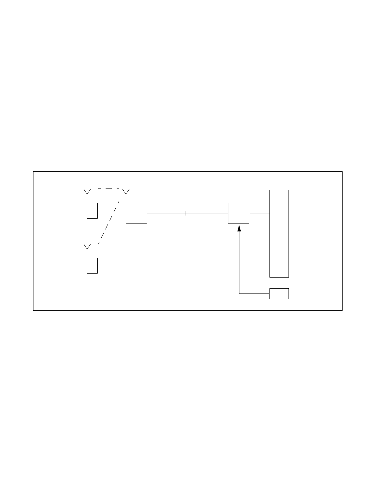
PA-4CSIC (CSINT)
PA-4CSIC (CSINT) : ZT (Zone Transceiver) Interface
1. General Functions
This circuit card is designed to provide the ISDN S interface to the Zone Transceiver (ZT).
Specifications and functions of this circuit card are shown below.
• A maximum of four ZTs can be accommodated in one 4CSIC circuit card.
• Interface with ZTs is based on the ISDN standard interface, though the multi-point connection of the
ZTs is not available.
• I.430, Q.921 Interface
[Each B Channel of 32 kbps in the 2B+D (B=64 kbps) can be used as two channels.]
• Feed functions to ZT: 48 Vtyp, maximum of 250 mA, feed polarity: reverse
• Equipped with 32k ADPCM (TSW: 64 kbps, ZT: 32 kbps)
• Burst syn ch ro n ization function of 5 m s (m u l t i-frame) to ZT
• Provided with 16 channels of PB (DTMF) sender
TSW
PS
ZT
Equiva lent to I . 43 0
PS
Figure 3-1 Location of Card in System
2. Mount ing Lo c a tion of Circui t Car d and Its Conditi ons
• Mounting location of circuit card: Universal slot of the PIM
Conditions: 12 CSINT circuit cards can be mounted in one PIM.
PA-4CSIC
5ms
PLO
CHAPTER 3 ND-70290 (E)
Page 44
Revision 3.0
Page 62

3. Lamp, Key, Connector and Their Location
The following diagram shows the location of Lamp, Key and Connectors.
SW12SW11
SW10
PA-4CSIC (CSINT)
OPE
NOPE
MB
BL34
BL33
BL32
BL31
LYR3
PWR3
BL24
BL23
BL22
BL21
LYR2
PWR2
BL14
BL13
BL12
BL11
LYR1
PWR1
BL04
BL03
BL02
BL01
LYR0
PWR0
SYNC
L3
L2
L1
L0
MODE
SWL3
SWL2
SWL1
SWL0
Figure 3-2 Lamp, Key and Connectors : PA-4CSIC
ND-70290 (E) CHAPTER 3
Page 45
Revision 3.0
Page 63

PA-4CSIC (CSINT)
4. Lamp Indication
Shown below are the contents of lamp indication on this circuit card.
LAMP NAME COLOR MEANING
OPE Green Remains lit when this card is operating normally.
NOPE Red R emains lit when this card is in make-busy state.
BLn4 Green Remains lit when B4 channel of the line #n is communicating
Flashing Flashes while the corresponding circuit is in make-busy state (60 IPM).
OFF Remains off when the corresponding circuit is idle.
BLn3 Green Remains lit when B3 channel of the line #n is communicating
Flashing Flashes while the corresponding circuit is in make-busy state (60 IPM).
OFF Remains off when the corresponding circuit is idle.
BLn2 Green Remains lit when B2 channel of line #n is communicating
Note 1
Flashing Flashes while the corresponding circuit is in make-busy state (60 IPM).
OFF Remains off when the corresponding circuit is idle.
BLn1 Green Remains lit when B1 channel of the line #n is communicating
Flashing Flashes while the corresponding circuit is in make-busy state (60 IPM).
OFF Remains off when the corresponding circuit is idle.
LYRn Green Remains lit when the layer 2 link of line #n is established
Flashing Flashes when layer 1 of the line #n is synchronized (120 IPM).
OFF Layer 1 and Layer 2 have not been established.
PWRn Red Lights when the power supply of the line #n fails.
SYNC Red Flashes when the synchronous timing of 5 ms is disconnected.
Note 1
Note 1
Note 1
n=0~3
Note 1:
CHAPTER 3 ND-70290 (E)
Page 46
Revision 3.0
B1 through B4 channels represent channel names of 32k ADPCM.
Page 64

5. Switch Settings
Standard settings of switches on this circuit card are shown in the table below.
PA-4CSIC (CSINT)
SWITCH NAME
MB
(Toggle Switch)
MBR
OFF
No. 3
No. 2
No. 1
No. 0
(Piano-Key Switch)
MODE
(Rotary Switch)
ON (MB)
OFF
ON
SWITCH
NUMBER
0
1
2
3
SWITCH
SETTING
STANDARD
SETTING
MEANING
Up Circuit card make-busy set
Circuit card make-busy cancel
Down
ON Line 0 make-busy request
OFF × Line 0 make-busy request cancel
ON Line 1 make-busy request
OFF × Line 1 make-busy request cancel
ON Line 2 make-busy request
OFF × Line 2 make-busy request cancel
ON Line 3 make-busy request
OFF × Line 3 make-busy request cancel
0
1
2
3~F
Echo Canceller is not effective
Not used
Echo Canceller is effective
Not used
SW10
ON
234
1
(DIP Switch)
1OFF ×
2ON ×
3ON ×
4ON ×
Fixed
Fixed
Fixed
Fixed
ND-70290 (E) CHAPTER 3
Page 47
Revision 3.0
Page 65

PA-4CSIC (CSINT)
SWITCH NAME
SW11
ON
1234
(DIP Switch)
567
8
SWITCH
NUMBER
1
2
3
4
SWITCH
SETTING
STANDARD
SETTING
PAD on TSW side
SWITCH 1 SWITCH 2 PAD
OFF OFF Not used
ON OFF A- L aw
OFF ON µ (P S) -A (T S W ) Conversio n
ON ON µ-Law (Standard Setting)
PAD on LINE side
SWITCH 3 SWITCH 4 PAD
OFF OFF Not used
ON OFF A- L aw
OFF ON µ (P S) -A (T S W ) Conversio n
ON ON µ-Law (Standard Setting)
PB Sender Mode (Law/Level) Selection
MEANING
SWITCH 5 SWITCH 6 LAW/LEVEL
5
Note:
6
OFF OFF
ON OFF
OFF ON
ON ON
µ/A-law can be selected on the TSW side PAD.
µ-law Standard =High: -7.0 dBm
Low: -9.0 dBm
A-law Standard =High: -8.0 dBm
Low: -10.0 dBm
7ON × Fixed
8ON × Fixed
Not used
µ-law Standard
A-law Standard
Note
CHAPTER 3 ND-70290 (E)
Page 48
Revision 3.0
Page 66

[Firmware: SW-329]
PA-4CSIC (CSINT)
SWITCH NAME
SW12
ON
1234
(DIP Switch)
567
SWITCH
NUMBER
8
1~3
4~6
SWITCH
SETTING
PAD control (PAD value of the TSW side)
SWITCH 1 SWITCH 2 SWITCH 3 PAD VALUE OF THE TSW SIDE
OFF OFF OFF Not used
ON OFF OFF PAD 2=0 dB, PAD 1=–5 dB
OFF ON OFF PAD 2=0 dB, PAD 1=–3 dB
ON ON OFF PAD 2=0 dB, PAD 1=0 dB
OFF OFF ON No t used
ON OFF ON
OFF ON ON PAD 2=0 dB, PAD 1=3 dB
ON ON ON PAD 2=0 dB, PAD 1=0 dB
PAD control (PAD value of the line side)
SWITCH 4 SWITCH 5 SWITCH 6 PAD VALUE OF THE LINE SIDE
OFF OFF OFF
ON OFF OFF
OFF ON OFF
ON ON OFF
OFF OFF ON
ON OFF ON PAD 4=0 dB, PAD 3=5 dB
OFF ON ON
ON ON ON
STANDARD
SETTING
MEANING
Note 1
PAD 2=0 dB, PAD 1=5 dB
(Standard setting)
Note 1
Not used
PAD 4=0 dB, PAD 3=–5 dB
PAD 4=0 dB, PAD 3=–3 dB
PAD 4=0 dB, PAD 3=0 dB
Not used
PAD 4=0 dB, PAD 3=3 dB
PAD 4=0 dB, PAD 3=0 dB
(Standard setting)
Note 1:
Note:
7OFF × Fixed
8OFF × Fixed
The following diagram shows the PAD control method.
(If MODE=0)
Echo Canceller
PAD 1
TSW Side
PAD 2 PAD 4
(In the case of MODE=0)
PAD 3
Line Side
The Echo Canceller, PAD 3 and PAD 4 are bypassed when the mode switch is set to “0.”
ND-70290 (E) CHAPTER 3
Page 49
Revision 3.0
Page 67

PA-4CSIC (CSINT)
[Firmware: SW-359]
SWITCH NAME
SW12
ON
1234
(DIP Switch)
567
SWITCH
NUMBER
1~8
8
SWITCH
SETTING
Connection with C.O. if Echo Canceller is not effective. Note 1 Connection with C.O. if Echo Canceller is effective. Note 2
SWITCH 1 SWITCH 2 SWITCH 3 PAD VALUE SWITCH 1 SWITCH 2 SWITCH 3 PAD VALUE
OFF OFF OFF Not used OFF OFF OFF Not used
ON OFF OFF Not used ON OFF OFF Not used
OFF ON OFF PAD 1=3 dB OFF ON OFF PAD 3=3 dB
ON ON OFF PAD 1=0 dB ON ON OFF PAD 3=0 dB
OFF OFF ON PAD 1=–3 dB OFF OFF ON PAD 3=–3 dB
ON OFF ON
OFF ON ON PAD 1=–7 dB OFF ON ON PAD 3=–7 dB
ON ON ON PAD 1=–10 dB ON ON ON PAD 3=–10 dB
SWITCH 4 PAD VALUE SWITCH 4 PAD VALUE
ON PAD 2=3 dB (Standard setting) ON PAD 4=3 dB (Standard setting)
OFF PAD 2=0 dB OFF PAD 4=0 dB
Connection with a station if Echo Canceller is not effective. Note 1 Connection with a station if Echo Canceller is effective. Note 2
SWITCH 5 SWITCH 6 SWITCH 7 PAD VALUE SWITCH 5 SWITCH 6 SWITCH 7 PAD VALUE
OFF OFF OFF Not used OFF OFF OFF Not used
ON OFF OFF PAD 1=5 dB ON OFF OFF PAD 3=5 dB
OFF ON OFF PAD 1=3 dB OFF ON OFF PAD 3=3 dB
ON ON OFF
OFF OFF ON PAD 1=–3 dB OFF OFF ON PAD 3=–3 dB
ON OFF ON PAD 1=–5 dB ON OFF ON PAD 3=–5 dB
OFF ON ON PAD 1=–7 dB OFF ON ON PAD 3=–7 dB
ON ON ON PAD 1=–10 dB ON ON ON PAD 3=–10 dB
STANDARD
SETTING
PAD 1=–5 dB
(Standard setting)
PAD 1=0 dB
(Standard setting)
MEANING
ON OFF ON
ON ON OFF
PAD 3=–5 dB
(Standard setting)
PAD 3=0 dB
(Standard setting)
Note 1:
Note:
SWITCH 8 PAD VALUE SWITCH 8 PAD VALUE
ON PAD 2=3 dB ON PAD 4=3 dB
OFF PAD 2=0 dB (Standard setting) OFF PAD 4=0 dB (Standard setting)
The following diagram shows the PAD control method.
(If MODE=0)
Echo Cancelle r
PAD1
TSW Side
PAD3
Line Side
PAD2 PAD4
(If MODE=0)
The Echo Can ce ll er, PAD 3 and PAD 4 are bypassed when the mode switch is set to “0.”
Note 2:
Pad value of both PAD 1 and PAD 2 is 0 dB.
CHAPTER 3 ND-70290 (E)
Page 50
Revision 3.0
Page 68

PA-4CSIC (CSINT)
SWITCH NAME
SWL0
SWL1
SWL2
SWL3
(Rotary Switch)
SWITCH
NUMBER
SWITCH
SETTING
STANDARD
SETTING
MEANING
Setting of the cable length to the
corresponding ZT
Note 1
SWL0: Channel 0
SWL1: Channel 1
SWL2: Channel 2
SWL3: Channel 3
0 0 ~ 262 ft (0~80 m)
1 262 ~ 524 ft (80 ~ 160 m)
2 524 ~ 787 ft (160 ~ 240 m)
3 787 ~ 1049 ft (240 ~ 320 m)
4 1049 ~ 1312 ft (320 ~ 400 m)
5 1312 ~ 1574 ft (400 ~ 480 m)
6 1574 ~ 1837 ft (480 ~ 560 m)
7 1837 ~ 2099 ft (560 ~ 640 m)
8 2099 ~ 2362 ft (640 ~ 720 m)
9 2362 ~ 2624 ft (720 ~ 800 m)
A 2624 ~ 2887 ft (800 ~ 880 m)
B 2887 ~ 3149 ft (880 ~ 960 m)
C 3149 ~ 3412 ft (960 ~ 1040 m)
D 3412 ~ 3674 ft (1040 ~ 1120 m)
E 3674 ~ 3937 ft (1120 ~ 1200 m)
F 3937 ft (1200 m) or more
Note 1:
SWL0~SW L3 det ermin es the ca ble l ength from CSINT to ZT, however the maximum leng th of each cable
varies according to the diameter of the cable.
Power supply from Built-in PCS system (Without arrestor, when feed output is 48V)
Diameter
Distance
(No arrestor)
26 AWG (0.4 φ) 24 AWG ( 0.5 φ) 22 AWG (0 .65 φ) 19 AWG (0.9 φ)
762 m 1219 m 1676 m 2438 m
2500 ft 4000 ft 5500 ft 8000 ft
Local power supply (With arrestor)
Diameter
Distance
(No arrestor)
26 AWG (0.4 φ) 24 AWG ( 0.5 φ) 22 AWG (0 .65 φ) 19 AWG (0.9 φ)
1189 m 1341 m 1676 m 2438 m
3900 ft 4400 ft 5500 ft 8000 ft
ND-70290 (E) CHAPTER 3
Page 51
Revision 3.0
Page 69

PA-4CSIC (CSINT)
PA-4CSIC (CSINT) : ZT (Zone Transceiver) Interface
Table 3-1 Switch Setting Table
MODULE
NAME
SLOT
SWITCH
NAME
SWITCH SHAPE REMARKS
PIM MB ON : Make-busy set of circuit
ON (MB)
OFF
OFF : Make-busy cancel of
card
circuit car d
MBR
No. 3
No. 2
No. 1
No. 0
OFF
ON
MODE
SW10
SW11
ON
ON
1234
1
234
567
8
SW12
ON
1234
SWL0
SWL1
SWL2
SWL3
CHAPTER 3 ND-70290 (E)
Page 52
Revision 3.0
567
8
Page 70

PA-4CSIC (CSINT)
6. External i n terface
Below are accommodation of the LT connector leads of this circuit card and connecting route diagram.
a. LT Connector Lead Accommodation when this circuit card is mounted in PIM.
LT Connector Accommodation
Accommodated in *1
Accommodated in *2
Accommodated in *3
LT0, 2, 4, 6, 8, 10 Conn e ct o r
26
27
28
29
30
31
32
33
34
RB0
TB0
35
36
RB1
TB1
37
RB2
38
TB2
39
RB3
40
TB3
41
42
43
44
45
46
47
48
49
50
LT Connector Name
Slot No.
10
11
12
13
14
15
16
17
18
19
20
21
22
23
24
25
LT1, 3, 5, 7, 9,11 C o nn ec t o r
1
2
3
4
5
6
7
8
9
RA0
TA0
RA1
TA1
RA2
TA2
RA3
TA3
26
27
28
29
30
31
32
33
34
35
36
37
38
39
40
41
42
43
44
45
46
47
48
49
50
RB0
TB0
RB1
TB1
RB2
TB2
RB3
TB3
10
11
12
13
14
15
16
17
18
19
20
21
22
23
24
25
1
RA0
TA0
2
3
RA1
TA1
4
RA2
5
TA2
6
RA3
7
TA3
8
9
LT1, 3, 5, 7, 9, 11 Connector
26
27
28
29
30
31
32
33
34
35
36
37
38
39
40
41
42
RB0
43
TB0
44
RB1
45
TB1
46
RB2
47
TB2
48
RB3
49
TB3
50
LT6 LT7 LT8 LT9 LT10 LT11LT0 LT1 LT2 LT3 LT4 LT5
10
11
12
13
14
15
16
17
18
19
20
21
22
23
24
25
1
2
3
4
5
6
7
8
9
RA0
TA0
RA1
TA1
RA2
TA2
RA3
TA3
232221201918171615141312111009080706050403020100
Group No.
Highway Block
PIM
*
*
2
1
0 1 32
*
*
1
3
110907050301
100806040200
**
*
32
2
1*2*3
4 5
231915
221814
211713
201612
*
*
1
*
3
6 7 98
Figure 3-3 LT Connector Leads Accommodation of PIM : PA-4CSIC
ND-70290 (E) CHAPTER 3
110907050301
100806040200
*
1
*
*
3
2
231915
221814
211713
201612
*
1
10
*
*
3
2
11
Page 53
Revision 3.0
Page 71

PA-4CSIC (CSINT)
PBX
CSINT
MDF
TA
TB
RA
RB
RA
RB
TA
TB
Figure 3-4 Connecting Route Diagram
IN
ZT
OUT
CHAPTER 3 ND-70290 (E)
Page 54
Revision 3.0
Page 72

PA-4CSID (CSINT) : ZT (Zone Transceiver) Interface
1. General Functions
This card is a line circuit card which accommodates Zone Transceivers (ZTs) via the ISDN U interface. ZTs
are to be connected using NT1.
The main specifications and functions of this circuit card are shown below.
• A maximum number of four ZTs can be accommodated in one circuit card.
• Interface with the NT1 is based on the standard ISDN interface. (U reference-point Echo Canceller
method.
ANSI TI.601, Q.921 interface)
• Two B channels of each 32 kbps can be used in 2B+D with the total speed of 64 kbps.
• Sealing current (Maximum 15mA) can be supplied to protect cables from rusting.
• Equipped with ADPCM which enables the B-channel bit rate to change. (TSW-side: 64 kbps, ZT side:
32 kbps)
PS
ZT
I.430
NT1
PA-4CSID (CSINT)
TSW
PA-4CSID
ANSI TI.601
PS
Figure 3-5 Location of Card in System
2. Mount ing Lo c a tion of Circui t Car d and Its Conditi ons
• Mounting location of circuit card: Universal slot of the PIM
Conditions: 12 CSINT circuit cards can be mounted in one PIM
PLO
ND-70290 (E) CHAPTER 3
Page 55
Revision 3.0
Page 73

PA-4CSID (CSINT)
3. Lamps, Switches, Connectors and Their Location
The following diagram shows the location of Lamp, Key and Connectors.
SW12
SW11
SW20
SW10
MBR
LPB
OPE
NOPE
MB
BL34
BL33
BL32
BL31
LYR3
BER3
BL14
BL13
BL12
BL11
LYR1
BER1
L3
L2
L1
L0
L3
L2
L1
L0
MODE
BL24
BL23
BL22
BL21
LYR2
BER2
BL04
BL03
BL02
BL01
LYR0
BER0
SW21
Figure 3-6 Lamp, Key and Connectors : PA-4CSID
MONITOR (Not used)
CHAPTER 3 ND-70290 (E)
Page 56
Revision 3.0
Page 74

4. Lamp Indication
Shown below are the contents of lamp indication on this circuit card.
LAMP NAME COLOR MEANING
OPE Green R emains lit when the card is operating normal ly.
NOPE Red Remains lit when the card is in make-busy state.
PA-4CSID (CSINT)
BLn4
BLn3
BLn2
BLn1
LYRn
Green Remains lit when B4 channel of the line #n is communicating (
Note
).
Flashing Flashes while the corresponding circuit is in make-busy state (60 IPM).
Off Remains off while the corresponding circuit is idle.
Green Rem ai n s l it wh en B3 channe l o f th e line #n is communicating (
Note
).
Flashing Flashes while the corresponding circuit is in make-busy state (60 IPM).
Off Remains off while the corresponding circuit is idle.
Green Rem ai n s l it wh en B2 channe l o f li n e #n is communicatin g (
Note
).
Flashing Flashes while the corresponding circuit is in make-busy state (60 IPM).
Off Remains off while the corresponding circuit is idle.
Green Rem ai n s l it wh en B1 channe l o f th e line #n is communicating (
Note
).
Flashing Flashes while the corresponding circuit is in make-busy state (60 IPM).
Off Remains off while the corresponding circuit is idle.
Green Remains lit when the layer 2 link of line #n is established.
Flashes when synchronization is established on Layer 1 of S Reference Point
(60 IPM).
Flashing
Flashes when synchronizat ion is establi she d on Layer 1 of U Reference Point
(120 IPM).
n=0~3
Note 1:
Note 2:
Off Synchronization is not established on both Layer 1 and Layer 2.
BERn
Red
Two or more CRC errors occ ur per second and the condition lasts for 10
seconds.
Off One or no CRC error occurs per second.
B1 through B4 channels represent channel names of 32K ADPCM.
Establishment of synchronization on U Reference Point may take 30 seconds or more.
ND-70290 (E) CHAPTER 3
Page 57
Revision 3.0
Page 75
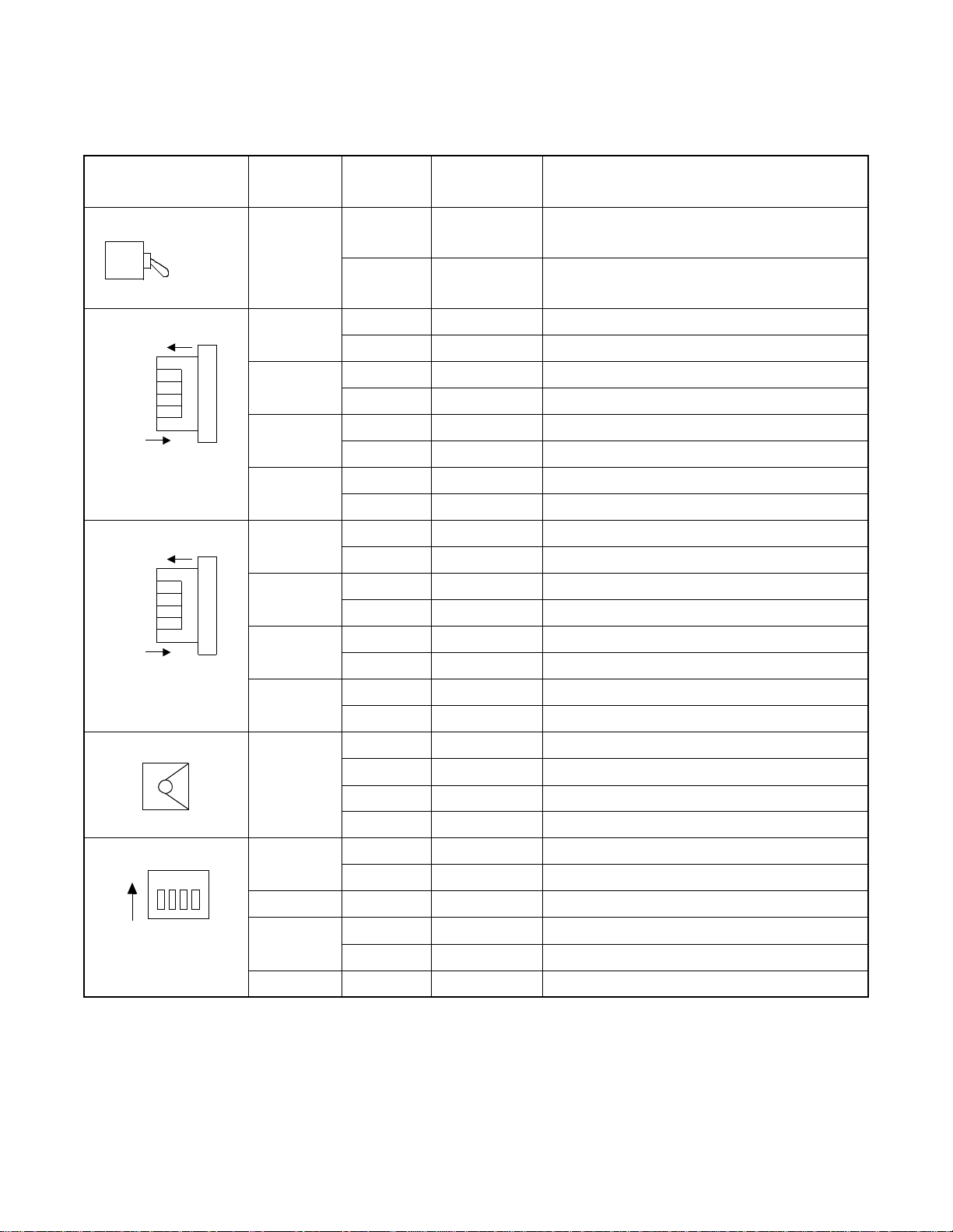
PA-4CSID (CSINT)
5. Switch Settings
Switches on this card have the following meanings.
SWITCH NAME
MB
(Toggle Switch)
MBR
OFF
No. 3
No. 2
No. 1
No. 0
(Piano Switch)
LPB
OFF
No. 3
No. 2
No. 1
No. 0
(Piano Switch)
ON (MB)
OFF
ON
ON
SWITCH
NUMBER
0
1
2
3
0
1
2
3
SWITCH
SETTING
UP
DOWN ×
STANDARD
SETTING
MEANING
Circuit card make-busy
Circuit card make-busy cancel
ON Line 0 make-busy request
OFF × Line 0 make-busy request cancel
ON Line 1 make-busy request
OFF × Line 1 make-busy request cancel
ON Line 2 make-busy request
OFF × Line 2 make-busy request cancel
ON Line 3 make-busy request
OFF × Line 3 make-busy request cancel
ON Loop back is set on NT1 for line 0.
OFF × Loop back is canceled on NT1 for line 0.
ON Loop back is set on NT1 for line 1.
OFF × Loop back is canceled on NT1 for line 1.
ON Loop back is set on NT1 for line 2.
OFF × Loop back is canceled on NT1 for line 2.
ON Loop back is set on NT1 for line 3.
OFF × Loop back is canceled on NT1 for line 3.
MODE
0 Ec ho Canceller is not effective
1Not used
2 E cho Can cel l er is effective
(Rotary Switch)
SW10
ON
1
1
234
3~F Not used
ON Mounted in WCS
OFF × Mounted in PCS
2ON × Fixed
(DIP Switch)
3
ON µ-law
OFF A-law
4ON × Fixed
CHAPTER 3 ND-70290 (E)
Page 58
Revision 3.0
Page 76

PA-4CSID (CSINT)
SWITCH NAME
SW11
ON
1234
(DIP Switch)
567
8
SWITCH
NUMBER
1
2
3
4
5
SWITCH
SETTING
STANDARD
SETTING
PAD on TSW side
SW1 SW2 PAD
OFF OFF Not used
ON OFF A-law
OFF ON µ (PS)-A(TSW) Conver sion
ON ON µ-law
PAD on LINE side
SW3 SW4 PAD
OFF OFF Not used
ON OFF A-law
OFF ON µ (PS)-A(TSW) Conversion
ON ON µ-law
PB Sender Mode (Law/Level)
ON
OFF
×
SW5 SW6 LAW/LEVEL
OFF OFF Not used
ON OFF
OFF ON
ON ON
MEANING
µ-law standard
A-law standard
Note
ON
6
OFF
7ON
8
ON Sealing Current is not supplied.
OFF
ND-70290 (E) CHAPTER 3
Note:
×
µ/A-law can be selected on the TSW side
PAD.
µ-law standard =High: –7.0 dBm
Low: –9.0 dBm
A-law standard = High: –8.0 dBm
Low: –10.0 dBm
×
×
Not used
Sealing Current is supplied.
Page 59
Revision 3.0
Page 77

PA-4CSID (CSINT)
[Firmware: SW-330]
SWITCH NAME
SW12
ON
1234
(DIP Switch)
567
SWITCH
NUMBER
8
1~3
4~6
SWITCH
SETTING
PAD control (TSW Side PAD Value)
SW1 SW2 SW3 TSW Side PAD Value
OFF OFF OFF Not used
ON OFF OFF PAD 2=0 dB, PAD 1=–5 dB
OFF ON OFF PAD 2=0 dB, PAD 1=–3 dB
ON ON OFF PAD 2=0 dB, PAD 1=0 dB
OFF OFF ON Not used
ON OFF ON
OFF ON ON PAD 2=0 dB, PAD 1= 3 dB
ON ON ON PAD 2=0 dB, PAD 1=0 dB
PAD control (Line Side PAD Value)
SW4 SW5 SW6 Line Sid e PAD Va lu e
OFF OFF OFF
ON OFF OFF
OFF ON OFF
ON ON OFF
OFF OFF ON
ON OFF ON
OFF ON ON
ON ON ON
STANDARD
SETTING
MEANING
Note 1
PAD 2=0 dB, PAD 1=5 dB
(Standard setting)
Note 1
Not used
PAD 4=0 dB, PAD 3=–5 dB
PAD 4=0 dB, PAD 3=–3 dB
PAD 4=0 dB, PAD 3=0 dB
Not used
PAD 4=0 dB, PAD 3=5 dB
(Standard Setting)
PAD 4=0 dB, PAD 3=3 dB
PAD 4=0 dB, PAD 3=0 dB
Note 1:
Note 2:
7OFF × Fixed
8OFF × Fixed
PAD control is shown below. Note that Echo Canceller, PAD 3 and PAD 4 are bypassed when the MODE
switch is set to “0”.
(If MODE=0)
Echo Canceller
PAD 1
TSW Side
PAD 2 PAD 4
(If MODE=0)
PAD 3
Line Si de
Regarding speech communication, PAD values set on SW12-1 through SW12-6 are applied. In the other
cases (ex. data communication), PAD values are set according to the order of CPU.
CHAPTER 3 ND-70290 (E)
Page 60
Revision 3.0
Page 78

[Firmware: SW-360]
SWITCH NAME
SW12
ON
1234
(DIP Switch)
567
8
SWITCH
NUMBER
1~8
PA-4CSID (CSINT)
SWITCH
SETTING
Connection with C.O. if Echo Canceller is not effective.
SWITCH 1 SWITCH 2 SWITCH 3 PAD VALUE SWITCH 1 SWITCH 2 SWITCH 3 PAD VALUE
OFF OFF OFF Not used OFF OFF OFF Not used
ON OFF OFF Not used ON OFF OFF Not used
OFF ON OFF PAD 1=3 dB OFF ON OFF PAD 3=3 dB
ON ON OFF PAD 1=0 dB ON ON OFF PAD 3=0 dB
OFF OFF ON PAD 1=–3 dB OFF OFF ON PAD 3=–3 dB
ON OFF ON
OFF ON ON PAD 1=–7 dB OFF ON ON PAD 3=–7 dB
ON ON ON PAD 1=–10 dB ON ON ON PAD 3=–10 dB
SWITCH 4 PAD VALUE SWITCH 4 PAD VALUE
ON PAD 2=3 dB (Standard setting) ON PAD 4=3 dB (Standard setting)
OFF PAD 2=0 dB OFF PAD 4=0 dB
Connection with station if Echo Canceller is not effective.
SWITCH 5 SWITCH 6 SWITCH 7 PAD VALUE SWITCH 5 SWITCH 6 SWITCH 7 PAD VALUE
OFF OFF OFF Not used OFF OFF OFF Not used
ON OFF OFF PAD 1=5 dB ON OFF OFF PAD 3=5 dB
OFF ON OFF PAD 1=3 dB OFF ON OFF PAD 3=3 dB
ON ON OFF
OFF OFF ON PAD 1=–3 dB OFF OFF ON PAD 3=–3 dB
ON OFF ON PAD 1=–5 dB ON OFF ON PAD 3=–5 dB
OFF ON ON PAD 1=–7 dB OFF ON ON PAD 3=–7 dB
ON ON ON PAD 1=–10 dB ON ON ON PAD 3=–10 dB
STANDARD
SETTING
Note
PAD 1=–5 dB
(Standard setting)
Note
PAD 1=0 dB
(Standard setting)
MEANING
Connectio n wi th C.O. if Echo Ca nc eller is effec t i ve.
ON OFF ON
Connection with station if Echo Canceller is effective.
ON ON OFF
PAD 3=–5 dB
(Standard setting)
PAD 3=0 dB
(Standard setting)
Note
Note
Note 1:
Note 2:
SWITCH 8 PAD VALUE SWITCH 8 PAD VALUE
ON PAD 2=3 dB ON PAD 4=3 dB
OFF PAD 2=0 dB (Standard setting) OFF PAD 4=0 dB (Standard setting)
PAD control is shown below. Note that Echo Canceller, PAD 3 and PAD 4 are bypassed when the MODE
switch is set to “0”.
(If MODE=0)
Echo Canceller
PAD 1
TSW Side
PAD 2 PAD 4
(If MODE=0)
PAD 3
Line Side
Pad value of both PAD 1 and PAD 2 is 0 dB.
ND-70290 (E) CHAPTER 3
Page 61
Revision 3.0
Page 79

PA-4CSID (CSINT)
SWITCH NAME
SWITCH
NUMBER
SWITCH
SETTING
STANDARD
SETTING
SW20 1 OFF × Fixed
ON
123
4
2OFF × Fixed
3OFF × Fixed
(DIP Switch)
4OFF ×
Fixed
SW21 1 ON × Not used
ON
1234
567
8
2ON × Not used
3ON × Not used
(DIP Switch)
4ON × Not used
5ON × Not used
6ON × Not used
7ON × Not used
8ON × Fixed
MEANING
CHAPTER 3 ND-70290 (E)
Page 62
Revision 3.0
Page 80

PA-4CSID (CSINT)
6. External i n terface
Shown below are accommodation of the LT connector leads of this circuit card and connecting route
diagram.
a. When this circuit card is mounted in PIM.
LT Connecto r Accomm odation
Accommodated in *1
Accomm odated in *2
Accommodated in *3
LT0, 2, 4, 6, 8, 10 Connector
26
27
28
29
30
31
32
33
34
B0
B1
35
36
B2
B3
37
38
39
40
41
42
43
44
45
46
47
48
49
50
LT Connector Name
Slot No.
Group No.
10
11
12
13
14
15
16
17
18
19
20
21
22
23
24
25
LT1, 3, 5, 7, 9,11 Connector
1
2
3
4
5
6
7
8
9
A0
A1
A2
A3
26
27
28
29
30
31
32
33
34
35
36
37
38
39
40
41
42
43
44
45
46
47
48
49
50
B0
B1
B2
B3
1
A0
A1
2
A2
3
A3
4
5
6
7
8
9
10
11
12
13
14
15
16
17
18
19
20
21
22
23
24
25
110907050301
100806040200
231915
221814
211713
201612
LT1, 3, 5, 7, 9, 11 Connector
26
27
28
29
30
31
32
33
34
35
36
37
38
39
40
41
B0
42
B1
43
B2
44
B3
45
46
47
48
49
50
LT6 LT7 LT8 LT9 LT10 LT11LT0 LT1 LT2 LT3 LT4 LT5
10
11
12
13
14
15
16
17
18
19
20
21
22
23
24
25
1
2
3
4
5
6
7
8
9
A0
A1
A2
A3
232221201918171615141312111009080706050403020100
110907050301
100806040200
231915
221814
211713
201612
PWR
PIM
Highway Block
PWR
*
*
2
1
0 1 32
*
*
1
3
**
*
32
2
1*2*3
4 5
*
*
1
6 7 98
Figure 3-7 LT Connector Leads Accommodation of PIM : PA-4CSID
ND-70290 (E) CHAPTER 3
*
*
*
1
3
*
*
3
2
*
10
*
2
3
11
1
Page 63
Revision 3.0
Page 81

PA-4CSID (CSINT)
MDF
PIM
CSINT
A
B
A
B
Figure 3-8 Connecting Route Diagram
NT1
CHAPTER 3 ND-70290 (E)
Page 64
Revision 3.0
Page 82

PA-4CSIE (CSINT) : ZT (Zone Tra nscei ver) Inte rf ace
1. General Functions
This circuit card is designed to provide the ISDN S interface to the Zone Transceiver (ZT).
Specifications and functions of this circuit card are shown below.
• A maximum of four ZTs can be accommodated in one 4CSIE circuit card.
• Interface with ZTs is based on the ISDN standard interface, though the multi-point connection of the
ZTs is not available.
• I.430, Q.921 Interface
• (Each B Channel of 32 kbps in the 2B+D (B=64 kbps) can be used as two channels.)
• Feed functions to ZT: 48 Vtyp, maximum of 250 mA, feed polarity: reverse
• Equipped with 32k ADPCM (TSW: 64 kbps, ZT: 32 kbps)
• Burst syn ch ro n ization function of 5 m s (m u l t i-frame) to ZT
• Provided with 16 channels of PB (DTMF) sender
PA-4CSIE (CSINT)
TSW
PS
ZT
Equiva lent to I . 43 0
PS
Figure 3-9 Location of Card in System
2. Mount ing Lo c a tion of Circui t Car d and Its Conditi ons
• Mounting location of circuit card: Universal slot of the PIM
Conditions: 12 CSINT circuit cards can be mounted in one PIM.
PA-4CSIE
5ms
PLO
ND-70290 (E) CHAPTER 3
Page 65
Revision 3.0
Page 83

PA-4CSIE (CSINT)
3. Lamp, Key, Connector and Their Location
The following diagram shows the location of Lamp, Key and Connectors.
MBR
OPE
NOPE
MB
BL34
BL33
BL32
LYR3
PWR3
BL14
BL13
BL12
LYR1
PWR1
SYNC
L3
L2
L1
L0
MODE
BL24
BL23
BL22
LYR2
PWR2
BL04
BL03
BL02
LYR0
PWR0
SW12SW11
SW10
Figure 3-10 Lamp, Key and Connectors : PA-4CSIE
CHAPTER 3 ND-70290 (E)
Page 66
Revision 3.0
Page 84

4. Lamp Indication
Shown below are the contents of lamp indication on this circuit card.
LAMP NAME COLOR MEANING
OPE Green Remains lit when this card is operating normally.
NOPE Red R emains lit when this card is in make-busy state.
PA-4CSIE (CSINT)
BLn4 Green Remains lit when B4 channel of the line #n is communicating
Flashing Flashes while the corresponding circuit is in make-busy state (60 IPM).
OFF Remains off when the corresponding circuit is idle.
BLn3 Green Remains lit when B3 channel of the line #n is communicating
Flashing Flashes while the corresponding circuit is in make-busy state (60 IPM).
OFF Remains off when the corresponding circuit is idle.
BLn2 Green Remains lit when B2 channel of line #n is communicating
Note
Flashing Flashes while the corresponding circuit is in make-busy state (60 IPM).
OFF Remains off when the corresponding circuit is idle.
LYRn Green Remains lit when the layer 2 link of line #n is established
Flashing Flashes when layer 1 of the line #n is synchronized (120 IPM).
OFF Layer 1 and Layer 2 have not been established.
PWRn Red Lights when the power supply of the line #n fails.
SYNC Red Flashes when the synchronous timing of 5 ms is disconnected.
n=0~3
Note 1:
B2 through B4 channels represent channel names of 32k ADPCM.
Note
Note
ND-70290 (E) CHAPTER 3
Page 67
Revision 3.0
Page 85

PA-4CSIE (CSINT)
5. Switch Settings
Standard settings of switches on this circuit card are shown in the table below.
SWITCH NAME
MB
(Toggle Switch)
MBR
OFF
No. 3
No. 2
No. 1
No. 0
(Piano-Key Switch)
MODE
(Rotary Switch)
ON (MB)
OFF
ON
SWITCH
NUMBER
0
1
2
3
SWITCH
SETTING
STANDARD
SETTING
MEANING
Up Circuit card make-busy set
Circuit card make-busy cancel
Down
ON Line 0 make-busy request
OFF × Line 0 make-busy request cancel
ON Line 1 make-busy request
OFF × Line 1 make-busy request cancel
ON Line 2 make-busy request
OFF × Line 2 make-busy request cancel
ON Line 3 make-busy request
OFF × Line 3 make-busy request cancel
Fixed
0 ×
Not used
1~F
SW10
ON
234
1
(DIP Switch)
1
ON
OFF ×
2ON ×
3ON ×
4ON ×
Mounted in WCS
Mounted in PCS
Fixed
Fixed
Fixed
CHAPTER 3 ND-70290 (E)
Page 68
Revision 3.0
Page 86

PA-4CSIE (CSINT)
SWITCH NAME
SW11
ON
1234
(DIP Switch)
567
8
SWITCH
NUMBER
SWITCH
SETTING
STANDARD
SETTING
PAD on TSW side
1
2
SWITCH 1 SWITCH 2 PAD
OFF OFF Not used
ON OFF A- L aw
OFF ON µ (P S) -A (T S W ) Conversio n
ON ON µ-Law (Standard Setting)
3ON × Not used
4ON × Not used
PB Sender Mode (Law/Level) Selection
SWITCH 5 SWITCH 6 LAW/LEVEL
5
OFF OFF
ON OFF
OFF ON
ON ON
MEANING
Not used
µ-law Standard
A-law Standard
Note
Note:
6
µ/A-law can be selected on the TSW si de PA D .
µ-law Standar d =High : -7.0 dBm
Low : -9.0 dBm
A-law Standar d =High : -8.0 dBm
Low : -10.0 dBm
7ON × Fixed
8ON × Fixed
ND-70290 (E) CHAPTER 3
Page 69
Revision 3.0
Page 87

PA-4CSIE (CSINT)
SWITCH NAME
SW12
ON
1234
(DIP Switch)
SWITCH
NUMBER
1~8
8
67
5
SWITCH
SETTING
Connection with C.O. Note
SWITCH 1 SWITCH 2 SWITCH 3 PAD VALUE
SWITCH 4 PAD VALUE
Connection with a station. Note
SWITCH 5 SWITCH 6 SWITCH 7 PAD VALUE
STANDARD
SETTING
MEANING
OFF OFF OFF Not used
ON OFF OFF Not used
OFF ON OFF PAD 1=3 dB
ON ON OFF PAD 1=0 dB
OFF OFF ON PAD 1=–3 dB
ON OFF ON PAD 1=–5 dB
(Standard setting)
OFF ON ON PAD 1=–7 dB
ON ON ON PAD 1=–10 dB
ON PAD 2=3 dB (Standard setting)
OFF PAD 2=0 dB
OFF OFF OFF Not used
ON OFF OFF PAD 1=5 dB
OFF ON OFF PAD 1=3 dB
ON ON OFF PAD 1=0 dB
(Standard setting)
OFF OFF ON PAD 1=–3 dB
ON OFF ON PAD 1=–5 dB
OFF ON ON PAD 1=–7 dB
ON ON ON PAD 1=–10 dB
SWITCH 8 PAD VALUE
ON PAD 2=3 dB
OFF PAD 2=0 dB (Standard setting)
Note:
The following diagram shows the PAD control method.
PAD 1
TSW Side
PAD 2
CHAPTER 3 ND-70290 (E)
Page 70
Revision 3.0
Line Si de
Page 88

PA-4CSIE (CSINT) : ZT (Zone Transceiver) Interface
PA-4CSIE (CSINT)
MODULE
NAME
SLOT
SWITCH
NAME
SWITCH SHAPE REMARKS
PIM MB ON : Make-busy set of circuit
ON (MB)
OFF
OFF : M ake-busy cancel of
card
circuit c ard
MBR
OFF
No. 3
No. 2
No. 1
No. 0
ON
MODE
SW10
SW11
ON
ON
1234
4
23
1
8
567
SW12
ON
123
4
567
8
ND-70290 (E) CHAPTER 3
Page 71
Revision 3.0
Page 89

PA-4CSIE (CSINT)
6. External i n terface
Below are accommodation of the LT connector leads of this circuit card and connecting route diagram.
a. LT Connector Lead Accommodation when this circuit card is mounted in PIM.
LT Connector Accommodation
Accommodated in *1
Accommodated in *2
Accommodated in *3
LT0, 2, 4, 6, 8, 10 Conn e ct o r
26
27
28
29
30
31
32
33
34
RB0
TB0
35
36
RB1
TB1
37
RB2
38
TB2
39
RB3
40
TB3
41
42
43
44
45
46
47
48
49
50
LT Connector Name
Slot No.
10
11
12
13
14
15
16
17
18
19
20
21
22
23
24
25
LT1, 3, 5, 7, 9,11 C o nn ec t o r
1
2
3
4
5
6
7
8
9
RA0
TA0
RA1
TA1
RA2
TA2
RA3
TA3
26
27
28
29
30
31
32
33
34
35
36
37
38
39
40
41
42
43
44
45
46
47
48
49
50
RB0
TB0
RB1
TB1
RB2
TB2
RB3
TB3
10
11
12
13
14
15
16
17
18
19
20
21
22
23
24
25
1
RA0
TA0
2
3
RA1
TA1
4
RA2
5
TA2
6
RA3
7
TA3
8
9
LT1, 3, 5, 7, 9, 11 Connector
26
27
28
29
30
31
32
33
34
35
36
37
38
39
40
41
42
RB0
43
TB0
44
RB1
45
TB1
46
RB2
47
TB2
48
RB3
49
TB3
50
LT6 LT7 LT8 LT9 LT10 LT11LT0 LT1 LT2 LT3 LT4 LT5
10
11
12
13
14
15
16
17
18
19
20
21
22
23
24
25
1
2
3
4
5
6
7
8
9
RA0
TA0
RA1
TA1
RA2
TA2
RA3
TA3
232221201918171615141312111009080706050403020100
110907050301
Group No.
100806040200
*
PIM
Highway Block
*
2
1
0 1 32
*
*
1
3
**
*
32
2
1*2*3
Figure 3-11 LT Connector Leads Accommodation of PIM : PA-4CSIE
CHAPTER 3 ND-70290 (E)
Page 72
Revision 3.0
4 5
231915
221814
211713
201612
*
*
1
*
3
6 7 98
110907050301
100806040200
*
1
*
*
3
2
231915
221814
211713
201612
*
1
10
*
*
3
2
11
Page 90

PBX
CSINT
MDF
TA
TB
RA
RB
RA
RB
TA
TB
Figure 3-12 Connecting Route Diagram
PA-4CSIE (CSINT)
IN
ZT
OUT
ND-70290 (E) CHAPTER 3
Page 73
Revision 3.0
Page 91

PA-4CSIF (CSINT)
PA-4CSIF (CSINT) : ZT (Zone Transceiver) Interface
1. General Functions
This card is a line circuit card which accommodates Zone Transceivers (ZTs) via the ISDN U interface. ZTs
are to be connected using NT1.
The main specifications and functions of this circuit card are shown below.
• A maximum of four ZTs can be accommodated in one circuit card.
• Interface with the NT1 is based on the standard ISDN interface. (U reference-point Echo Canceller
method. ANSI TI.601, Q.921 interface)
• Two B channels of each 32 kbps can be used in 2B+D with the total speed of 64 kbps.
• Sealing current (Maximum 15 mA) can be supplied to protect cables from rusting.
• Equipped with ADPCM which enables the B-channel bit rate to change. (TSW-side: 64 kbps, ZT side:
32 kbps)
PS
ZT
I.430
NT1
TSW
PA-4CSIF
ANSI TI.601
PS
Figure 3-13 Location of Card in System
2. Mount ing Lo c a tion of Circui t Car d and Its Conditi ons
• Mounting location of circuit card: Universal slot of the PIM
Conditions: 12 CSINT circuit cards can be mounted in one PIM
PLO
CHAPTER 3 ND-70290 (E)
Page 74
Revision 3.0
Page 92
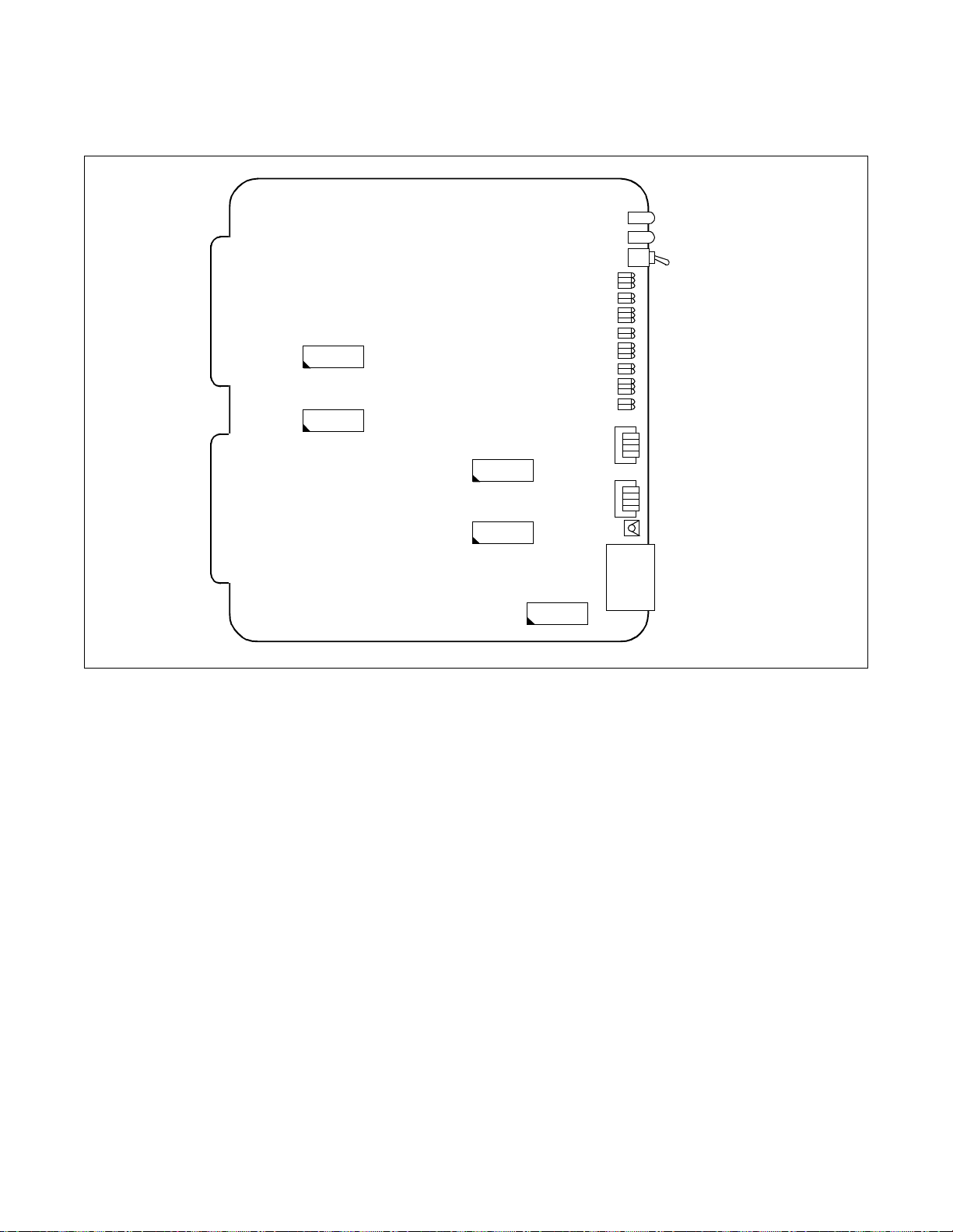
3. Lamps, Switches, Connectors and Their Location
The following diagram shows the location of Lamp, Key and Connectors.
SW12
SW11
SW20
SW10
MBR
LPB
OPE
NOPE
MB
BL34
BL33
BL32
LYR3
BER3
BL24
BL23
BL22
LYR2
BER2
BL14
BL13
BL12
LYR1
BER1
BL04
BL03
BL02
LYR0
BER0
L3
L2
L1
L0
L3
L2
L1
L0
MODE
PA-4CSIF (CSINT)
SW21
Figure 3-14 Lamp, Key and Connectors : PA-4CSIF
MONITOR (Not used)
ND-70290 (E) CHAPTER 3
Page 75
Revision 3.0
Page 93

PA-4CSIF (CSINT)
4. Lamp Indication
Shown below are the contents of lamp indication on this circuit card.
LAMP NAME COLOR MEANING
OPE Green R emains lit when the card is operating normal ly.
NOPE Red Remains lit when the card is in make-busy state.
BLn4
BLn3
BLn2
LYRn
BERn
Green Remains lit when B4 channel of the line #n is communicating (
Note
).
Flashing Flashes while the corresponding circuit is in make-busy state (60 IPM).
Off Remains off while the corresponding circuit is idle.
Green Rem ai n s l it wh en B3 channe l o f th e line #n is communicating (
Note
).
Flashing Flashes while the corresponding circuit is in make-busy state (60 IPM).
Off Remains off while the corresponding circuit is idle.
Green Rem ai n s l it wh en B2 channe l o f li n e #n is communicatin g (
Note
).
Flashing Flashes while the corresponding circuit is in make-busy state (60 IPM).
Off Remains off while the corresponding circuit is idle.
Green Remains lit when the layer 2 link of line #n is established.
Flashes when synchronization is established on Layer 1 of S Reference Point
(60 IPM).
Flashing
Flashes when synchronizat ion is establi she d on Layer 1 of U Reference Point
(120 IPM).
Off Synchronization is not established on both Layer 1 and Layer 2.
Red
Two or more CRC errors occ ur per second and the condition lasts for 10
seconds.
Off One or no CRC error occurs per second.
n=0~3
Note 1:
Note 2:
CHAPTER 3 ND-70290 (E)
Page 76
Revision 3.0
B2 through B4 channels represent channel names of 32K ADPCM.
Establishment of synchronization on U Reference Point may take 30 seconds or more.
Page 94

5. Switch Settings
Switches on this card have the following meanings.
PA-4CSIF (CSINT)
SWITCH NAME
MB
(Toggle Switch)
MBR
OFF
No. 3
No. 2
No. 1
No. 0
(Piano Switch)
LPB
OFF
No. 3
No. 2
No. 1
No. 0
(Piano Switch)
ON (MB)
OFF
ON
ON
SWITCH
NUMBER
0
1
2
3
0
1
2
3
SWITCH
SETTING
UP
DOWN ×
STANDARD
SETTING
MEANING
Circuit card make-busy
Circuit card make-busy cancel
ON Line 0 make-busy request
OFF × Line 0 make-busy request cancel
ON Line 1 make-busy request
OFF × Line 1 make-busy request cancel
ON Line 2 make-busy request
OFF × Line 2 make-busy request cancel
ON Line 3 make-busy request
OFF × Line 3 make-busy request cancel
ON Loop back is set on NT1 for Line 0.
OFF × Loop back is canceled on NT1 for Line 0.
ON Loop back is set on NT1 for Line 1.
OFF × Loop back is canceled on NT1 for Line 1.
ON Loop back is set on NT1 for Line 2.
OFF × Loop back is canceled on NT1 for Line 2.
ON Loop back is set on NT1 for Line 3.
OFF × Loop back is canceled on NT1 for Line 3.
MODE
(Rotary Switch)
SW10
ON
(DIP Switch)
1
234
0 ×
1~F
1
ON Mounted in WCS
Fixed
Not used
OFF × Mounted in PCS
2ON × Fixed
ON ×µ-law
3
OFF A-law
4ON × Fixed
ND-70290 (E) CHAPTER 3
Page 77
Revision 3.0
Page 95

PA-4CSIF (CSINT)
SWITCH NAME
SWITCH
NUMBER
SWITCH
SETTING
SW11 1 ON
ON
1234
567
8
2ON
3ON
4ON
(DIP Switch)
ON
5
OFF
ON
6
OFF
STANDARD
SETTING
×
×
×
×
×
×
MEANING
Fixed
Fixed
Fixed
Fixed
PB Sender Mode (Law/Level)
SW5 SW6 LAW/LEVEL
OFF OFF Not used
ON OFF
OFF ON
µ-law standard
A-law standard
Note:
ON ON
µ/A-law can be selected on the TSW side
PAD.
µ-law standard =High: –7.0 dBm
Low: –9.0 dBm
A-law standard = High: –8.0 dBm
Low: –10.0 dBm
Note
7ON
8
ON Sealing Current is not supplied.
OFF
×
×
Not used
Sealing Current is supplied.
CHAPTER 3 ND-70290 (E)
Page 78
Revision 3.0
Page 96

[Firmware: SW-360]
N
PA-4CSIF (CSINT)
SWITCH NAME
SW12
ON
1234
(DIP Switch)
567
8
SWITCH
NUMBER
1~8
SWITCH
SETTING
Connection wit h C. O.
SWITCH 1 SWITCH 2 SWITCH 3 PAD VALUE
SWITCH 4 PAD VALUE
STANDARD
SETTING
MEANING
ote
OFF OFF OFF Not used
ON OFF OFF Not used
OFF ON OFF PAD 1=3 dB
ON ON OFF PAD 1=0 dB
OFF OFF ON PAD 1=–3 dB
ON OFF ON PAD 1=–5 dB
(Standa rd settin g)
OFF ON ON PAD 1=–7 dB
ON ON ON PAD 1=–10 dB
ON PAD 2=3 dB (Standard setting)
OFF PAD 2=0 dB
Connection wit h a statio n Note
SWITCH 5 S WITCH 6 SWITCH 7 PAD VALUE
OFF OFF OFF Not used
ON OFF OFF PAD 1=5 dB
OFF ON OFF PAD 1=3 dB
ON ON OFF PAD 1=0 dB
(Standard setting)
OFF OFF ON PAD 1=–3 dB
ON OFF ON PAD 1=–5 dB
OFF ON ON PAD 1=–7 dB
ON ON ON PAD 1=–10 dB
Note 1:
PAD control is shown below.
TSW Side
SWITCH 8 PAD VALUE
ON PAD 2=3 dB
OFF PAD 2=0 dB (Standard setting)
PAD 1
Line Si de
PAD 2
ND-70290 (E) CHAPTER 3
Page 79
Revision 3.0
Page 97

PA-4CSIF (CSINT)
SWITCH NAME
SWITCH
NUMBER
SWITCH
SETTING
STANDARD
SETTING
SW20 1 OFF × Fixed
ON
123
4
2OFF × Fixed
3OFF × Fixed
(DIP Switch)
4OFF ×
Fixed
SW21 1 ON × Not used
ON
1234
567
8
2ON × Not used
3ON × Not used
(DIP Switch)
4ON × Not used
5ON × Not used
6ON × Not used
7ON × Not used
8ON × Fixed
MEANING
CHAPTER 3 ND-70290 (E)
Page 80
Revision 3.0
Page 98

PA-4CSIF (CSINT) : ZT (Zone Transceiver) Interface
Switch Setting Table
PA-4CSIF (CSINT)
MODULE
NAME
SLOT
SWITCH
NAME
SWITCH SHAPE REMARKS
PIM MB ON : Make-busy set of circuit
ON
card
OFF : Make-busy cancel of
circuit car d
MBR
LPB
No. 3
No. 2
No. 1
No. 0
No. 3
No. 2
No. 1
No. 0
OFF
ON
OFF
ON
MODE
0
SW10
SW11
SW12
SW20
SW21
ON
ON
ON
ON
1234
123
ON
123
1
4
1
23
567
567
234
567
4
4
8
8
8
ND-70290 (E) CHAPTER 3
Page 81
Revision 3.0
Page 99

PA-4CSIF (CSINT)
6. External i n terface
Shown in Figure 3-15 are accommodation of the LT connector leads of this circuit card and connec ting route
diagram.
a. When this circuit card is mounted in PIM.
LT Connecto r Accomm odation
Accommodated in *1
Accomm odated in *2
Accommodated in *3
LT0, 2, 4, 6, 8, 10 Connector
26
27
28
29
30
31
32
33
34
B0
35
B1
36
B2
37
B3
38
39
40
41
42
43
44
45
46
47
48
49
50
LT Connector Name
Slot No.
Group No.
10
11
12
13
14
15
16
17
18
19
20
21
22
23
24
25
LT1, 3, 5, 7, 9,11 Connector
1
2
3
4
5
6
7
8
9
A0
A1
A2
A3
26
27
28
29
30
31
32
33
34
35
36
37
38
39
40
41
42
43
44
45
46
47
48
49
50
B0
B1
B2
B3
1
A0
A1
2
3
A2
A3
4
5
6
7
8
9
10
11
12
13
14
15
16
17
18
19
20
21
22
23
24
25
110907050301
100806040200
231915
221814
211713
201612
LT1, 3, 5, 7, 9, 11 Connector
26
27
28
29
30
31
32
33
34
35
36
37
38
39
40
41
B0
42
B1
43
B2
44
B3
45
46
47
48
49
50
LT6 LT7 LT8 LT9 LT10 LT11LT0 LT1 LT2 LT3 LT4 LT5
10
11
12
13
14
15
16
17
18
19
20
21
22
23
24
25
1
2
3
4
5
6
7
8
9
A0
A1
A2
A3
232221201918171615141312111009080706050403020100
110907050301
100806040200
231915
221814
211713
201612
PWR
PIM
Highway Block
PWR
*
*
2
1
0 1 32
*
*
1
3
**
*
32
2
1*2*3
Figure 3-15 LT Connector Leads Accommodation of PIM : PA-4CSIF
CHAPTER 3 ND-70290 (E)
Page 82
Revision 3.0
4 5
*
*
1
6 7 98
*
*
3
*
1
2
*
*
1
3
10
*
*
3
2
11
Page 100

PIM
PA-4CSIF (CSINT)
MDF
CSINT
A
B
A
B
Figure 3-16 Connecting Route Diagram
NT1
ND-70290 (E) CHAPTER 3
Page 83
Revision 3.0
 Loading...