

Page 1

®
ND-46248 (E)
ISSUE 2
STOCK # 151937
WCS System Manual
JULY, 1998
NEC America, Inc.
Page 2

Page 3

LIABILITY DISCLAIMER
NEC America, Inc. reserves the right to change the specifications,
functions, or features, at any time, without notice.
NEC America, Inc . has prepared this doc ume nt for u se by its employees and cus tomers. The information contained herein is the
property of NEC America, Inc. and shall not be reproduced without
prior written approval from NEC America, Inc.
NEAX and D
term
are registered trademarks of NEC Corporation.
Copyright 1998
NEC America, Inc.
Printed in USA
Page 4

Page 5

PAGE No.
i 2.1
ii 2.1
iii
iv
v
vi
vii
viii
1
2
3
4
5
6
7
8
9
10
11
12 2.1
13 2.1
14 2.1
15 2.1
15-1
15-2 2.1
16 2.1
17
18
19
20
21
22
23
24
25
26
27
28
ADDENDUM-001 ADDENDUM-002 ADDENDUM-003 ADDENDUM-004
DATE MARCH, 1999 DATE DATE DATE
ADDENDUM-005 ADDENDUM-006 ADDENDUM-007 ADDENDUM-008
DA TE DATE DA TE DATE
001 002 003 004 005 006 007 008
2.1
ADD. No.
PAGE No.
001 002 003 004 005 006 007 008
29
30
31
32
33
34
35
36
37
38
39
40
41
42
43
44
45
46
47
48
49
50
51
52
53
54
55
56
57
58
59
60
61
62
63
64
65
66
ADD. No.
NEAX2000 IVS
WCS System Manual
Addendum Revision Sheet 1/3
ND-46248 (E) ISSUE 2
Page 6

PAGE No.
001 002 003 004 005 006 007 008
67
68
69
70
71
72
73
74
75
76
77
78
79
80
81
82
83
84
85
86
87 2.1
88
89
90
91
92
93
94
95
96
97
98
99
100
101
102
103
104
ADDENDUM-001 ADDENDUM-002 ADDENDUM-003 ADDENDUM-004
DATE MARCH, 1999 DATE DATE DATE
ADDENDUM-005 ADDENDUM-006 ADDENDUM-007 ADDENDUM-008
DA TE DATE DA TE DATE
ADD. No.
PAGE No.
105
106
107
108
109
110
111
112
113
114
115 2.1
115-1 2.1
115-2 2.1
116
117 2.1
118 2.1
119
120
121
122 2.1
123 2.1
124
125
126
127
128
129
130
131
132
133
134
135
136 2.1
137 2.1
138
139
140
001 002 003 004 005 006 007 008
2.1
ADD. No.
NEAX2000 IVS
WCS System Manual
Addendum Revision Sheet 2/3
ND-46248 (E) ISSUE 2
Page 7

PAGE No.
141
142
143
143-1 2.1
143-2 2.1
144 2.1
145
146
147
148
149 2.1
150
151
152
153
154 2.1
155
156
157 2.1
158
159
160
161 2.1
162
163
164
165
166
167
168
169
170
171
172
173
174
175 2.1
176
ADDENDUM-001 ADDENDUM-002 ADDENDUM-003 ADDENDUM-004
DATE MARCH, 1999 DATE DATE DATE
ADDENDUM-005 ADDENDUM-006 ADDENDUM-007 ADDENDUM-008
DA TE DATE DA TE DATE
001 002 003 004 005 006 007 008
2.1
ADD. No.
PAGE No.
001 002 003 004 005 006 007 008
177
178 2.1
179
180 2.1
181
182
183
184
185
186
187
188
189
190
191
192
193
194
195
196
197
198
198-1 2.1
198-2 2.1
199 2.1
200
201
202
203
204
205
206
ADD. No.
NEAX2000 IVS
WCS System Manual
Addendum Revision Sheet 3/3
ND-46248 (E) ISSUE 2
Page 8

Page 9

NEAX2000 IVS ND-46248 (E)
WCS System Manual ISSUE 2
Addendum-001
MARCH, 1999
GENERAL
This addendum supplements the “NEAX2000 IVS WCS System Manual [ND-46248 (E)].”
REASON FOR ISSUE
This addendum is issued in order to add the 1900 Series Release 2 enhancements and to correct errors.
PAGE REPLACEMENT INSTRUCTION
Replace pages: i, ii, 12 ~ 16, 87, 115, 116 ~118, 122, 123, 136, 137, 144, 149, 154, 157, 158, 161, 175, 178, 180,
199.
Add pages: 15-1, 15-2, 115-1, 115-2, 143-1, 143-2, 198-1, 198-2.
Page 10

Page 11

ND-46248 (E)
ISSUE 2
JULY, 1998
NEAX2000 IVS
WCS System Manual
TABLE OF CONTENTS
Page
LIST OF FIGURES . . . . . . . . . . . . . . . . . . . . . . . . . . . . . . . . . . . . . . . . . . . . . . . . . . . . . . . . . . . . . . . . . . . . . . . . . v
LIST OF TABLES . . . . . . . . . . . . . . . . . . . . . . . . . . . . . . . . . . . . . . . . . . . . . . . . . . . . . . . . . . . . . . . . . . . . . . . . . vii
CHAPTER 1 INTRODUCTION. . . . . . . . . . . . . . . . . . . . . . . . . . . . . . . . . . . . . . . . . . . . . . . . . . . . . . . . . . . . . 1
1. PURPOSE . . . . . . . . . . . . . . . . . . . . . . . . . . . . . . . . . . . . . . . . . . . . . . . . . . . . . . . . . . . . . . . . . . . . . . . . 1
2. OUTLINE OF THE MANUAL . . . . . . . . . . . . . . . . . . . . . . . . . . . . . . . . . . . . . . . . . . . . . . . . . . . . . . . . . . 1
3. REFERENCE MANUALS. . . . . . . . . . . . . . . . . . . . . . . . . . . . . . . . . . . . . . . . . . . . . . . . . . . . . . . . . . . . . 1
CHAPTER 2 SYSTEM DESCRIPTION . . . . . . . . . . . . . . . . . . . . . . . . . . . . . . . . . . . . . . . . . . . . . . . . . . . . . . 3
1. GENERAL . . . . . . . . . . . . . . . . . . . . . . . . . . . . . . . . . . . . . . . . . . . . . . . . . . . . . . . . . . . . . . . . . . . . . . . . 3
2. SYSTEM CONFIGURATION . . . . . . . . . . . . . . . . . . . . . . . . . . . . . . . . . . . . . . . . . . . . . . . . . . . . . . . . . . 3
2.1 System Outline . . . . . . . . . . . . . . . . . . . . . . . . . . . . . . . . . . . . . . . . . . . . . . . . . . . . . . . . . . . . . . . 3
2.2 CSH. . . . . . . . . . . . . . . . . . . . . . . . . . . . . . . . . . . . . . . . . . . . . . . . . . . . . . . . . . . . . . . . . . . . . . . . 5
2.3 Outline of Circuit Cards . . . . . . . . . . . . . . . . . . . . . . . . . . . . . . . . . . . . . . . . . . . . . . . . . . . . . . . . . 9
3. SYSTEM SPECIFICATIONS . . . . . . . . . . . . . . . . . . . . . . . . . . . . . . . . . . . . . . . . . . . . . . . . . . . . . . . . . 11
3.1 System Specifications . . . . . . . . . . . . . . . . . . . . . . . . . . . . . . . . . . . . . . . . . . . . . . . . . . . . . . . . . 11
3.2 System Capacity . . . . . . . . . . . . . . . . . . . . . . . . . . . . . . . . . . . . . . . . . . . . . . . . . . . . . . . . . . . . . 12
3.3 Expanding PS Capacity. . . . . . . . . . . . . . . . . . . . . . . . . . . . . . . . . . . . . . . . . . . . . . . . . . . . . . . 15-1
3.4 Time Slot Assignment Conditions . . . . . . . . . . . . . . . . . . . . . . . . . . . . . . . . . . . . . . . . . . . . . . . . 16
3.4.1 Time Slots for CSH Card. . . . . . . . . . . . . . . . . . . . . . . . . . . . . . . . . . . . . . . . . . . . . . . . 16
3.4.2 Time Slots for CSI Card . . . . . . . . . . . . . . . . . . . . . . . . . . . . . . . . . . . . . . . . . . . . . . . . 16
4. OUTLINE OF MULTI-SITE ROAMING. . . . . . . . . . . . . . . . . . . . . . . . . . . . . . . . . . . . . . . . . . . . . . . . . . 17
4.1 Functional Outline . . . . . . . . . . . . . . . . . . . . . . . . . . . . . . . . . . . . . . . . . . . . . . . . . . . . . . . . . . . . 17
4.2 Multi-Site Roaming System Configuration . . . . . . . . . . . . . . . . . . . . . . . . . . . . . . . . . . . . . . . . . . 18
4.3 Summary of Multi-Site Roaming System Operation . . . . . . . . . . . . . . . . . . . . . . . . . . . . . . . . . . 20
4.4 Multi-Site Roaming System Condition . . . . . . . . . . . . . . . . . . . . . . . . . . . . . . . . . . . . . . . . . . . . . 22
CHAPTER 3 INSTALLATION . . . . . . . . . . . . . . . . . . . . . . . . . . . . . . . . . . . . . . . . . . . . . . . . . . . . . . . . . . . . . 23
1. GENERAL . . . . . . . . . . . . . . . . . . . . . . . . . . . . . . . . . . . . . . . . . . . . . . . . . . . . . . . . . . . . . . . . . . . . . . . 23
2. PRECAUTION IN HANDLING . . . . . . . . . . . . . . . . . . . . . . . . . . . . . . . . . . . . . . . . . . . . . . . . . . . . . . . . 23
3. EQUIPMENT AND CABLES . . . . . . . . . . . . . . . . . . . . . . . . . . . . . . . . . . . . . . . . . . . . . . . . . . . . . . . . . 26
4. INSTALLATION PROCEDURE. . . . . . . . . . . . . . . . . . . . . . . . . . . . . . . . . . . . . . . . . . . . . . . . . . . . . . . . 28
4.1 AC Power Cable Wiring . . . . . . . . . . . . . . . . . . . . . . . . . . . . . . . . . . . . . . . . . . . . . . . . . . . . . . . . 30
4.2 Mounting PWRM/PIM . . . . . . . . . . . . . . . . . . . . . . . . . . . . . . . . . . . . . . . . . . . . . . . . . . . . . . . . . 33
4.3 Mounting PWR Card . . . . . . . . . . . . . . . . . . . . . . . . . . . . . . . . . . . . . . . . . . . . . . . . . . . . . . . . . . 34
4.3.1 Mounting PW91 Card . . . . . . . . . . . . . . . . . . . . . . . . . . . . . . . . . . . . . . . . . . . . . . . . . . 34
4.3.2 Mounting PW00 Card . . . . . . . . . . . . . . . . . . . . . . . . . . . . . . . . . . . . . . . . . . . . . . . . . . 35
4.3.3 Mounting –48V PWR Unit to NEAX1000 IVS . . . . . . . . . . . . . . . . . . . . . . . . . . . . . . . . 37
4.4 Connection of Power Cables . . . . . . . . . . . . . . . . . . . . . . . . . . . . . . . . . . . . . . . . . . . . . . . . . . . . 41
ND-46248 (E) TABLE OF CONTENTS
Addendum-001 Page i
MARCH, 1999 Revision 2.1
Page 12

TABLE OF CONTENTS (CONTINUED)
Page
4.4.1 AC CORD . . . . . . . . . . . . . . . . . . . . . . . . . . . . . . . . . . . . . . . . . . . . . . . . . . . . . . . . . . . 41
4.4.2 1-PIM Configuration . . . . . . . . . . . . . . . . . . . . . . . . . . . . . . . . . . . . . . . . . . . . . . . . . . . 43
4.4.3 Multiple-PIM Configuration . . . . . . . . . . . . . . . . . . . . . . . . . . . . . . . . . . . . . . . . . . . . . . 45
4.4.4 PW00 Card and PW86 Card Connection . . . . . . . . . . . . . . . . . . . . . . . . . . . . . . . . . . . 50
4.4.5 PWR CNT CA-A and PWR CA-WK Connection . . . . . . . . . . . . . . . . . . . . . . . . . . . . . . 51
4.5 Connection of BUS Cables . . . . . . . . . . . . . . . . . . . . . . . . . . . . . . . . . . . . . . . . . . . . . . . . . . . . . 52
4.6 Switch Settings of Circuit Cards . . . . . . . . . . . . . . . . . . . . . . . . . . . . . . . . . . . . . . . . . . . . . . . . . 55
4.6.1 Switch Settings of PW91 Card . . . . . . . . . . . . . . . . . . . . . . . . . . . . . . . . . . . . . . . . . . . 56
4.6.2 Switch Settings of PW00 Card . . . . . . . . . . . . . . . . . . . . . . . . . . . . . . . . . . . . . . . . . . . 58
4.6.3 Switch Settings of CSH Card . . . . . . . . . . . . . . . . . . . . . . . . . . . . . . . . . . . . . . . . . . . . 60
4.6.4 Switch Settings of CSI Card . . . . . . . . . . . . . . . . . . . . . . . . . . . . . . . . . . . . . . . . . . . . . 63
4.7 Mounting FP Card . . . . . . . . . . . . . . . . . . . . . . . . . . . . . . . . . . . . . . . . . . . . . . . . . . . . . . . . . . . . 67
4.8 Mounting CSI Card . . . . . . . . . . . . . . . . . . . . . . . . . . . . . . . . . . . . . . . . . . . . . . . . . . . . . . . . . . . 68
4.9 Mounting CSH Card. . . . . . . . . . . . . . . . . . . . . . . . . . . . . . . . . . . . . . . . . . . . . . . . . . . . . . . . . . . 71
4.10 Connection of ZT. . . . . . . . . . . . . . . . . . . . . . . . . . . . . . . . . . . . . . . . . . . . . . . . . . . . . . . . . . . . . 74
4.11 Connection of Battery . . . . . . . . . . . . . . . . . . . . . . . . . . . . . . . . . . . . . . . . . . . . . . . . . . . . . . . . . 80
4.11.1 Internal Battery Connection . . . . . . . . . . . . . . . . . . . . . . . . . . . . . . . . . . . . . . . . . . . . . 82
4.11.2 Battery Connection in PWRM . . . . . . . . . . . . . . . . . . . . . . . . . . . . . . . . . . . . . . . . . . . . 87
4.11.3 Battery Connection in BATTM. . . . . . . . . . . . . . . . . . . . . . . . . . . . . . . . . . . . . . . . . . . . 90
5. INSTALLATION FOR MULTI-SITE ROAMING . . . . . . . . . . . . . . . . . . . . . . . . . . . . . . . . . . . . . . . . . . . . 96
5.1 Installation Procedure for Multi-Site Roaming . . . . . . . . . . . . . . . . . . . . . . . . . . . . . . . . . . . . . . . 96
5.2 Mounting DTI, DCH and DBM Card. . . . . . . . . . . . . . . . . . . . . . . . . . . . . . . . . . . . . . . . . . . . . . . 97
5.3 Selection of PLO in MP Card. . . . . . . . . . . . . . . . . . . . . . . . . . . . . . . . . . . . . . . . . . . . . . . . . . . 103
5.4 Mounting PLO Card. . . . . . . . . . . . . . . . . . . . . . . . . . . . . . . . . . . . . . . . . . . . . . . . . . . . . . . . . . 106
5.5 Cable Connection via MDF for DTI . . . . . . . . . . . . . . . . . . . . . . . . . . . . . . . . . . . . . . . . . . . . . . 107
CHAPTER 4 SYSTEM DATA PROGRAMMING. . . . . . . . . . . . . . . . . . . . . . . . . . . . . . . . . . . . . . . . . . . . . . 113
1. GENERAL . . . . . . . . . . . . . . . . . . . . . . . . . . . . . . . . . . . . . . . . . . . . . . . . . . . . . . . . . . . . . . . . . . . . . . 113
2. SYSTEM DATA PROGRAMMING INFORMATION . . . . . . . . . . . . . . . . . . . . . . . . . . . . . . . . . . . . . . . 113
3. PROGRAMMING PROCEDURE . . . . . . . . . . . . . . . . . . . . . . . . . . . . . . . . . . . . . . . . . . . . . . . . . . . . . 114
3.1 ZT Data Assignment . . . . . . . . . . . . . . . . . . . . . . . . . . . . . . . . . . . . . . . . . . . . . . . . . . . . . . . . . 116
3.2 ZT Set Up . . . . . . . . . . . . . . . . . . . . . . . . . . . . . . . . . . . . . . . . . . . . . . . . . . . . . . . . . . . . . . . . . 119
3.2.1 Initial Set Up of ZT . . . . . . . . . . . . . . . . . . . . . . . . . . . . . . . . . . . . . . . . . . . . . . . . . . . 119
3.2.2 Setting Up of Additional ZT . . . . . . . . . . . . . . . . . . . . . . . . . . . . . . . . . . . . . . . . . . . . . 120
3.3 PS Data Assignment . . . . . . . . . . . . . . . . . . . . . . . . . . . . . . . . . . . . . . . . . . . . . . . . . . . . . . . . . 121
3.4 Virtual Line/Trunk Data Assignment . . . . . . . . . . . . . . . . . . . . . . . . . . . . . . . . . . . . . . . . . . . . . 124
3.5 Trunk Data Assignment . . . . . . . . . . . . . . . . . . . . . . . . . . . . . . . . . . . . . . . . . . . . . . . . . . . . . . . 128
3.6 Service Feature Data Assignment. . . . . . . . . . . . . . . . . . . . . . . . . . . . . . . . . . . . . . . . . . . . . . . 133
3.6.1 Announcement Service. . . . . . . . . . . . . . . . . . . . . . . . . . . . . . . . . . . . . . . . . . . . . . . . 133
3.6.2 Call Forwarding-Not Available. . . . . . . . . . . . . . . . . . . . . . . . . . . . . . . . . . . . . . . . . . . 137
3.6.3 Calling Name Display-PS . . . . . . . . . . . . . . . . . . . . . . . . . . . . . . . . . . . . . . . . . . . . . . 138
3.6.4 Group Call-Automatic Conference (6/10 Party) Data Assignment . . . . . . . . . . . . . . . 139
3.6.5 Group Call-2 Way Calling . . . . . . . . . . . . . . . . . . . . . . . . . . . . . . . . . . . . . . . . . . . . . . 141
3.6.6 Multi-Line Operation-PS . . . . . . . . . . . . . . . . . . . . . . . . . . . . . . . . . . . . . . . . . . . . . . . 142
3.6.7 Number Sharing . . . . . . . . . . . . . . . . . . . . . . . . . . . . . . . . . . . . . . . . . . . . . . . . . . . . 143-1
3.6.8 Voice Mail Indication . . . . . . . . . . . . . . . . . . . . . . . . . . . . . . . . . . . . . . . . . . . . . . . . . . 144
3.7 Multi-Site Roaming Data Assignment . . . . . . . . . . . . . . . . . . . . . . . . . . . . . . . . . . . . . . . . . . . . 145
3.7.1 Network Numbering Plan Assignment . . . . . . . . . . . . . . . . . . . . . . . . . . . . . . . . . . . . 146
3.7.2 Q931a Digital Trunk Assignment. . . . . . . . . . . . . . . . . . . . . . . . . . . . . . . . . . . . . . . . . 149
TABLE OF CONTENTS ND-46248 (E)
Page ii Addendum-001
Revision 2.1 MARCH, 1999
Page 13

TABLE OF CONTENTS (CONTINUED)
Page
3.7.3 Home PS Data Assignment . . . . . . . . . . . . . . . . . . . . . . . . . . . . . . . . . . . . . . . . . . . . 155
3.7.4 Visitor PS Data Assignment . . . . . . . . . . . . . . . . . . . . . . . . . . . . . . . . . . . . . . . . . . . . 157
3.8 Maintenance Data Assignment . . . . . . . . . . . . . . . . . . . . . . . . . . . . . . . . . . . . . . . . . . . . . . . . . 163
3.9 Maintenance Administration Terminal (MAT) . . . . . . . . . . . . . . . . . . . . . . . . . . . . . . . . . . . . . . . 164
3.9.1 Direct Connection . . . . . . . . . . . . . . . . . . . . . . . . . . . . . . . . . . . . . . . . . . . . . . . . . . . . 164
3.9.2 Remote Connection . . . . . . . . . . . . . . . . . . . . . . . . . . . . . . . . . . . . . . . . . . . . . . . . . . 165
4. DATA PROGRAMMING SHEETS . . . . . . . . . . . . . . . . . . . . . . . . . . . . . . . . . . . . . . . . . . . . . . . . . . . . 166
APPENDIX A OPERATING PROCEDURE FOR ANNOUNCEMENT SERVICE. . . . . . . . . . . . . . . . . . . . . . 205
ND-46248 (E) TABLE OF CONTENTS
Page iii
Revision 2.0
Page 14

This page is for your notes.
TABLE OF CONTENTS ND-46248 (E)
Page iv
Revision 2.0
Page 15

LIST OF FIGURES
Figure Title Page
Figure 2-1 System Diagram of WCS Integrated Type (1 of 2) . . . . . . . . . . . . . . . . . . . . . . . . . . . . . . . . . . . . . 3
Figure 2-1 System Diagram of WCS (2 of 2). . . . . . . . . . . . . . . . . . . . . . . . . . . . . . . . . . . . . . . . . . . . . . . . . . . 4
Figure 2-2 Module Configurations (1 of 4) . . . . . . . . . . . . . . . . . . . . . . . . . . . . . . . . . . . . . . . . . . . . . . . . . . . . 5
Figure 2-2 Module Configurations (2 of 4). . . . . . . . . . . . . . . . . . . . . . . . . . . . . . . . . . . . . . . . . . . . . . . . . . . . . 6
Figure 2-2 Module Configurations (3 of 4). . . . . . . . . . . . . . . . . . . . . . . . . . . . . . . . . . . . . . . . . . . . . . . . . . . . . 7
Figure 2-2 Module Configurations (4 of 4). . . . . . . . . . . . . . . . . . . . . . . . . . . . . . . . . . . . . . . . . . . . . . . . . . . . . 8
Figure 2-3 Accommodation of CSH into TDSW . . . . . . . . . . . . . . . . . . . . . . . . . . . . . . . . . . . . . . . . . . . . . . . 16
Figure 2-4 Functional Outline of Multi-Site Roaming . . . . . . . . . . . . . . . . . . . . . . . . . . . . . . . . . . . . . . . . . . . 17
Figure 2-5 System Configuration of Multi-Site Roaming . . . . . . . . . . . . . . . . . . . . . . . . . . . . . . . . . . . . . . . . 18
Figure 2-6 Location Registration System Operation . . . . . . . . . . . . . . . . . . . . . . . . . . . . . . . . . . . . . . . . . . . 20
Figure 2-7 Call Termination System Operation . . . . . . . . . . . . . . . . . . . . . . . . . . . . . . . . . . . . . . . . . . . . . . . 21
Figure 3-1 Static Electricity Precautions (1 of 2) . . . . . . . . . . . . . . . . . . . . . . . . . . . . . . . . . . . . . . . . . . . . . . 23
Figure 3-1 Static Electricity Precautions (2 of 2) . . . . . . . . . . . . . . . . . . . . . . . . . . . . . . . . . . . . . . . . . . . . . . . 24
Figure 3-2 Installation Procedure (1 of 2) . . . . . . . . . . . . . . . . . . . . . . . . . . . . . . . . . . . . . . . . . . . . . . . . . . . . 28
Figure 3-2 Installation Procedure (2 of 2) . . . . . . . . . . . . . . . . . . . . . . . . . . . . . . . . . . . . . . . . . . . . . . . . . . . . 29
Figure 3-3 Screwing AC CORD-B-U to Terminals . . . . . . . . . . . . . . . . . . . . . . . . . . . . . . . . . . . . . . . . . . . . . 30
Figure 3-4 Wiring AC CORD-B to Terminals . . . . . . . . . . . . . . . . . . . . . . . . . . . . . . . . . . . . . . . . . . . . . . . . . 31
Figure 3-5 Wiring AC CORD (A) to Terminals . . . . . . . . . . . . . . . . . . . . . . . . . . . . . . . . . . . . . . . . . . . . . . . . 32
Figure 3-6 Mounting of PWRM . . . . . . . . . . . . . . . . . . . . . . . . . . . . . . . . . . . . . . . . . . . . . . . . . . . . . . . . . . . . 33
Figure 3-7 Mounting PW91 Card into PWRM (Power Module Unit) . . . . . . . . . . . . . . . . . . . . . . . . . . . . . . . . 34
Figure 3-8 Mounting PW00 Card into PIM (1 of 2) . . . . . . . . . . . . . . . . . . . . . . . . . . . . . . . . . . . . . . . . . . . . . 35
Figure 3-8 Mounting PW00 Card into PIM (2 of 2) . . . . . . . . . . . . . . . . . . . . . . . . . . . . . . . . . . . . . . . . . . . . . 36
Figure 3-9 Fixing –48V PWR Unit to PWR MOUNT . . . . . . . . . . . . . . . . . . . . . . . . . . . . . . . . . . . . . . . . . . . . 37
Figure 3-10 Connecting PWR CA-WK . . . . . . . . . . . . . . . . . . . . . . . . . . . . . . . . . . . . . . . . . . . . . . . . . . . . . . . 38
Figure 3-11 PWR CA-WK . . . . . . . . . . . . . . . . . . . . . . . . . . . . . . . . . . . . . . . . . . . . . . . . . . . . . . . . . . . . . . . . . 39
Figure 3-12 Securing PWR MOUNT to PIM . . . . . . . . . . . . . . . . . . . . . . . . . . . . . . . . . . . . . . . . . . . . . . . . . . . 40
Figure 3-13 Connection of AC CORD (1 of 2) . . . . . . . . . . . . . . . . . . . . . . . . . . . . . . . . . . . . . . . . . . . . . . . . . 41
Figure 3-13 Connection of AC CORD (2 of 2). . . . . . . . . . . . . . . . . . . . . . . . . . . . . . . . . . . . . . . . . . . . . . . . . . 42
Figure 3-14 Connection of PWR-1.7 CA-WA and PWR CNT CA-B (For 1-PIM Configuration) (1 of 2) . . . . . . 43
Figure 3-14 Connection of PWR-1.7 CA-WA and PWR CNT CA-B (For 1-PIM Configuration) (2 of 2) . . . . . . 44
Figure 3-15 Connection of PWR-1.7 CA-WA (For a Multiple PIM Configuration) (1 of 2) . . . . . . . . . . . . . . . . 45
Figure 3-15 Connection of PWR-1.7 CA-WA (For a Multiple PIM Configuration) (2 of 2). . . . . . . . . . . . . . . . . 46
Figure 3-16 Connection of PWR CNT CA-A and PWR CNT CA-B (For a Multiple PIM Configuration) . . . . . . 47
Figure 3-17 PWR-1.7 CA-WA . . . . . . . . . . . . . . . . . . . . . . . . . . . . . . . . . . . . . . . . . . . . . . . . . . . . . . . . . . . . . 48
Figure 3-18 PWR CNT CA-A . . . . . . . . . . . . . . . . . . . . . . . . . . . . . . . . . . . . . . . . . . . . . . . . . . . . . . . . . . . . . . 49
Figure 3-19 PWR CNT CA-B . . . . . . . . . . . . . . . . . . . . . . . . . . . . . . . . . . . . . . . . . . . . . . . . . . . . . . . . . . . . . . 49
Figure 3-20 Connection of PWR CA-WC/4Q-TW-0.3 CONN CA/PWR CNT CA-A . . . . . . . . . . . . . . . . . . . . . 50
Figure 3-21 Connection of PWR CNT CA-A and PWR CA-WK . . . . . . . . . . . . . . . . . . . . . . . . . . . . . . . . . . . . 51
Figure 3-22 Mounting of BUS Cards . . . . . . . . . . . . . . . . . . . . . . . . . . . . . . . . . . . . . . . . . . . . . . . . . . . . . . . . 52
Figure 3-23 BUS Cable . . . . . . . . . . . . . . . . . . . . . . . . . . . . . . . . . . . . . . . . . . . . . . . . . . . . . . . . . . . . . . . . . . 53
Figure 3-24 Connection of BUS Cables . . . . . . . . . . . . . . . . . . . . . . . . . . . . . . . . . . . . . . . . . . . . . . . . . . . . . . 54
Figure 3-25 Locations of Switches, Lamps and Connectors on PW91 Card . . . . . . . . . . . . . . . . . . . . . . . . . . 56
Figure 3-26 Locations of Switches, Lamps and Connectors on PW00 Card . . . . . . . . . . . . . . . . . . . . . . . . . . 58
Figure 3-27 Locations of Switches and Lamps on CSH Card . . . . . . . . . . . . . . . . . . . . . . . . . . . . . . . . . . . . . 60
Figure 3-28 Locations of Switches and Lamps on CSI Card . . . . . . . . . . . . . . . . . . . . . . . . . . . . . . . . . . . . . . 63
Figure 3-29 MP/FP Card Mounting Slots . . . . . . . . . . . . . . . . . . . . . . . . . . . . . . . . . . . . . . . . . . . . . . . . . . . . . 67
Figure 3-30 Mounting Location of CSI Card (1 of 3) . . . . . . . . . . . . . . . . . . . . . . . . . . . . . . . . . . . . . . . . . . . . 68
Figure 3-30 Mounting Location of CSI Card (2 of 3) . . . . . . . . . . . . . . . . . . . . . . . . . . . . . . . . . . . . . . . . . . . . . 69
Figure 3-30 Mounting Location of CSI Card (3 of 3) . . . . . . . . . . . . . . . . . . . . . . . . . . . . . . . . . . . . . . . . . . . . . 70
ND-46248 (E) LIST OF FIGURES
Page v
Revision 2.0
Page 16

LIST OF FIGURES
Figure Title Page
Figure 3-31 Mounting Location of CSH Card (1 of 3) . . . . . . . . . . . . . . . . . . . . . . . . . . . . . . . . . . . . . . . . . . . . 71
Figure 3-31 Mounting Location of CSH Card (2 of 3) . . . . . . . . . . . . . . . . . . . . . . . . . . . . . . . . . . . . . . . . . . . . 72
Figure 3-31 Mounting Location of CSH Card (3 of 3) . . . . . . . . . . . . . . . . . . . . . . . . . . . . . . . . . . . . . . . . . . . . 73
Figure 3-32 Cable Connection via MDF for ZT . . . . . . . . . . . . . . . . . . . . . . . . . . . . . . . . . . . . . . . . . . . . . . . . 74
Figure 3-33 Location of LT Slots and LTC Connectors for ZT (1 of 3) . . . . . . . . . . . . . . . . . . . . . . . . . . . . . . . 75
Figure 3-33 Location of LT Slots and LTC Connectors for ZT (2 of 3) . . . . . . . . . . . . . . . . . . . . . . . . . . . . . . . 76
Figure 3-33 Location of LT Slots and LTC Connectors for ZT (3 of 3) . . . . . . . . . . . . . . . . . . . . . . . . . . . . . . . 77
Figure 3-34 Example of Cable Connection via MDF for ZT (1 of 2) . . . . . . . . . . . . . . . . . . . . . . . . . . . . . . . . . 78
Figure 3-34 Example of Cable Connection via MDF for ZT (2 of 2) . . . . . . . . . . . . . . . . . . . . . . . . . . . . . . . . . 79
Figure 3-35 Internal Battery Mounting (1 of 2) . . . . . . . . . . . . . . . . . . . . . . . . . . . . . . . . . . . . . . . . . . . . . . . . . 82
Figure 3-35 Internal Battery Mounting (2 of 2) . . . . . . . . . . . . . . . . . . . . . . . . . . . . . . . . . . . . . . . . . . . . . . . . . 83
Figure 3-36 Internal Battery Connection . . . . . . . . . . . . . . . . . . . . . . . . . . . . . . . . . . . . . . . . . . . . . . . . . . . . . 84
Figure 3-37 Internal Battery Connection for a Multiple PIM Configuration . . . . . . . . . . . . . . . . . . . . . . . . . . . . 85
Figure 3-38 PWR CA-A . . . . . . . . . . . . . . . . . . . . . . . . . . . . . . . . . . . . . . . . . . . . . . . . . . . . . . . . . . . . . . . . . . 86
Figure 3-39 Battery Connection into PWRM . . . . . . . . . . . . . . . . . . . . . . . . . . . . . . . . . . . . . . . . . . . . . . . . . . 87
Figure 3-40 Battery Mounting into PWRM . . . . . . . . . . . . . . . . . . . . . . . . . . . . . . . . . . . . . . . . . . . . . . . . . . . . 88
Figure 3-41 Battery Connection in PWRM . . . . . . . . . . . . . . . . . . . . . . . . . . . . . . . . . . . . . . . . . . . . . . . . . . . . 89
Figure 3-42 Battery Mounting into BATTM for PW86 Card . . . . . . . . . . . . . . . . . . . . . . . . . . . . . . . . . . . . . . . 90
Figure 3-43 Battery Connection in BATTM for PW86 Card . . . . . . . . . . . . . . . . . . . . . . . . . . . . . . . . . . . . . . . 91
Figure 3-44 Connection to PW86 Card . . . . . . . . . . . . . . . . . . . . . . . . . . . . . . . . . . . . . . . . . . . . . . . . . . . . . . 91
Figure 3-45 Connection of PWR CA-A for a Multiple PIM Configuration . . . . . . . . . . . . . . . . . . . . . . . . . . . . . 92
Figure 3-46 Battery Mounting into BATTM for PW91 Card . . . . . . . . . . . . . . . . . . . . . . . . . . . . . . . . . . . . . . . 93
Figure 3-47 Battery Connection in BATTM for PW91 Card . . . . . . . . . . . . . . . . . . . . . . . . . . . . . . . . . . . . . . . 94
Figure 3-48 Connection to PW91 Card . . . . . . . . . . . . . . . . . . . . . . . . . . . . . . . . . . . . . . . . . . . . . . . . . . . . . . 94
Figure 3-49 Connection of PWR CA-A/BATTERY CABLE . . . . . . . . . . . . . . . . . . . . . . . . . . . . . . . . . . . . . . . 95
Figure 3-50 Installation Procedure for Multi-Site Roaming . . . . . . . . . . . . . . . . . . . . . . . . . . . . . . . . . . . . . . . . 96
Figure 3-51 Switch Settings on DTI Card (1 of 2) . . . . . . . . . . . . . . . . . . . . . . . . . . . . . . . . . . . . . . . . . . . . . . 97
Figure 3-51 Switch Settings on DTI Card (2 of 2) . . . . . . . . . . . . . . . . . . . . . . . . . . . . . . . . . . . . . . . . . . . . . . . 98
Figure 3-52 Switch Settings on DCH Card . . . . . . . . . . . . . . . . . . . . . . . . . . . . . . . . . . . . . . . . . . . . . . . . . . . 100
Figure 3-53 Switch Settings on DBM Card . . . . . . . . . . . . . . . . . . . . . . . . . . . . . . . . . . . . . . . . . . . . . . . . . . . 101
Figure 3-54 Switch Settings on MP Card (1 of 3) . . . . . . . . . . . . . . . . . . . . . . . . . . . . . . . . . . . . . . . . . . . . . . 103
Figure 3-54 Switch Settings on MP Card (2 of 3) . . . . . . . . . . . . . . . . . . . . . . . . . . . . . . . . . . . . . . . . . . . . . . 104
Figure 3-54 Switch Settings on MP Card (3 of 3) . . . . . . . . . . . . . . . . . . . . . . . . . . . . . . . . . . . . . . . . . . . . . . 105
Figure 3-55 Switch Settings on PLO Card . . . . . . . . . . . . . . . . . . . . . . . . . . . . . . . . . . . . . . . . . . . . . . . . . . . 106
Figure 3-56 Cable Connection via MDF . . . . . . . . . . . . . . . . . . . . . . . . . . . . . . . . . . . . . . . . . . . . . . . . . . . . . 107
Figure 3-57 Location of AP Slots and LTC Connectors for DTI (1 of 3) . . . . . . . . . . . . . . . . . . . . . . . . . . . . . 108
Figure 3-57 Location of AP Slots and LTC Connectors for DTI (2 of 3) . . . . . . . . . . . . . . . . . . . . . . . . . . . . . 109
Figure 3-57 Location of AP Slots and LTC Connectors for DTI (3 of 3) . . . . . . . . . . . . . . . . . . . . . . . . . . . . . 110
Figure 3-58 Example of Cable Connection via MDF for DTI . . . . . . . . . . . . . . . . . . . . . . . . . . . . . . . . . . . . . 111
Figure 4-1 Cable Connection (Direct) . . . . . . . . . . . . . . . . . . . . . . . . . . . . . . . . . . . . . . . . . . . . . . . . . . . . . . 164
Figure 4-2 MAT Cable Connection (Remote Connection via Internal Modem) . . . . . . . . . . . . . . . . . . . . . . 165
Figure 4-3 MAT Cable Connection (Remote Connection via Modem) . . . . . . . . . . . . . . . . . . . . . . . . . . . . . 165
LIST OF FIGURES ND-46248 (E)
Page vi
Revision 2.0
Page 17

LIST OF TABLES
Table Title Page
Table 2-1 Functional Outline of Circuit Card. . . . . . . . . . . . . . . . . . . . . . . . . . . . . . . . . . . . . . . . . . . . . . . . . . . . 9
Table 2-2 System Specifications . . . . . . . . . . . . . . . . . . . . . . . . . . . . . . . . . . . . . . . . . . . . . . . . . . . . . . . . . . . 11
Table 2-3 NEAX2000 IVS WCS System Capacity . . . . . . . . . . . . . . . . . . . . . . . . . . . . . . . . . . . . . . . . . . . . . . 12
Table 2-4 Small Platform System WCS System Capacity . . . . . . . . . . . . . . . . . . . . . . . . . . . . . . . . . . . . . . . . 13
Table 2-5 NEAX1000 IVS WCS System Capacity (1 PIM Configuation) . . . . . . . . . . . . . . . . . . . . . . . . . . . . . 14
Table 2-6 NEAX1000 IVS WCS System Capacity (2 PIM Configuration) . . . . . . . . . . . . . . . . . . . . . . . . . . . . 15
Table 3-1 Required Equipment for WCS . . . . . . . . . . . . . . . . . . . . . . . . . . . . . . . . . . . . . . . . . . . . . . . . . . . . 26
Table 3-2 List of Circuit Cards . . . . . . . . . . . . . . . . . . . . . . . . . . . . . . . . . . . . . . . . . . . . . . . . . . . . . . . . . . . . . 55
Table 3-3 Switch Settings on PW91 Card . . . . . . . . . . . . . . . . . . . . . . . . . . . . . . . . . . . . . . . . . . . . . . . . . . . . 57
Table 3-4 Lamp Indications on PW91 Card . . . . . . . . . . . . . . . . . . . . . . . . . . . . . . . . . . . . . . . . . . . . . . . . . . . 57
Table 3-5 Switch Settings on PW00 Card . . . . . . . . . . . . . . . . . . . . . . . . . . . . . . . . . . . . . . . . . . . . . . . . . . . . 59
Table 3-6 Lamp Indication on PW00 Card . . . . . . . . . . . . . . . . . . . . . . . . . . . . . . . . . . . . . . . . . . . . . . . . . . . . 59
Table 3-7 Switch Settings on CSH Card. . . . . . . . . . . . . . . . . . . . . . . . . . . . . . . . . . . . . . . . . . . . . . . . . . . . . . 61
Table 3-8 Lamp Indications on CSH Card . . . . . . . . . . . . . . . . . . . . . . . . . . . . . . . . . . . . . . . . . . . . . . . . . . . . 62
Table 3-9 Switch Settings on CSI Card . . . . . . . . . . . . . . . . . . . . . . . . . . . . . . . . . . . . . . . . . . . . . . . . . . . . . . 64
Table 3-10 Lamp Indications on CSI Card . . . . . . . . . . . . . . . . . . . . . . . . . . . . . . . . . . . . . . . . . . . . . . . . . . . . . 65
Table 4-1 MAT Cable (Direct). . . . . . . . . . . . . . . . . . . . . . . . . . . . . . . . . . . . . . . . . . . . . . . . . . . . . . . . . . . . . 164
Table 4-2 MAT Cable (Remote Connection) . . . . . . . . . . . . . . . . . . . . . . . . . . . . . . . . . . . . . . . . . . . . . . . . . 165
ND-46248 (E) LIST OF TABLES
Page vii
Revision 2.0
Page 18

This page is for your notes.
LIST OF TABLES ND-46248 (E)
Page viii
Revision 2.0
Page 19

CHAPTER 1 INTRODUCTION
1. PURPOSE
This manual provi des the information nee ded for installing an d programming the syste m data to provide the Wirel ess
Communication System (WCS) on the NEAX2000 IVS/1000 IVS (PBX).
2. OUTLINE OF THE MANUAL
This manual consists of four chapters. The contents of Chapters 2 through 4 are as outlined as follows.
• CHAPTER 2 (SYSTEM DESCRIPTION)
This chapter explains the system configuration and system specifications required to provide the WCS on
the PBX.
• CHAPTER 3 (INSTALLATION)
This chapter explains the procedure for hardware installation which is required to provide the WCS on the
PBX.
• CHAPTER 4 (SYSTEM DATA PROGRAMMING)
This chapter explains the system data programming procedure required to assign the WCS.
3. REFERENCE MANUALS
When installi ng t he WCS and assi gni n g th e r elevant syst em d ata , refe r to the fo llowing m a nua l s in a d diti o n t o th is
manual.
• Installation Procedure Manual
• Feature Programming Manual
• Command Manual
• Office Data Programming Manual
• SMDR System Manual
• Circuit Card Manual
• MAT Operation Guide
• CCIS System Manual
• Small Plat form System Manual
• NEAX1000 IVS System Manual
ND-46248 (E) CHAPTER 1
Page 1
Revision 2.0
Page 20

This page is for your notes.
CHAPTER 1 ND-46248 (E)
Page 2
Revision 2.0
Page 21
CHAPTER 2 SYSTEM DESCRIPTION
1. GENERAL
This chapter explains the system configuration, additional hardware and system specifications pertaining to the
WCS.
2. SYSTEM CONFIGURATION
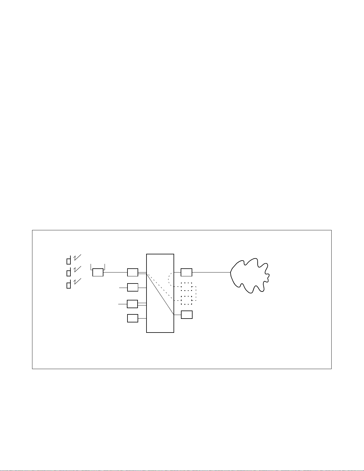
2.1 System Outline
The wireless communication system (WCS) is interfaced with a Personal Station (PS) via a Zone Transceiver
(ZT).
When installing the WCS, there are three types of systems:
1. Integrated Type
The NEAX2000 IVS/1000 IVS provides both PBX and WCS functions.
2. Adjunct Type [1]
The WCS is an adjunct system to the existing PBX linked by LC-COT connection.
3. Adjunct Type [2]
The WCS is an adjunct system to the existing PBX linked by CCIS.
Figure 2-1 shows the system diagram of the WCS.
(1) Integrated Type
WCS
PS
PS
PS
ZT
SLT
term
D
Figure 2-1 System Diagram of WCS Integrated Type (1 of 2)
CSI COT
LC
DLC
DAT
LC
COT
CSH
PSTN
*
PS : Personal Station
ZT : Zone Transceiver
CSI : ZT Interface
CSH : ZT Handler
DAT : Digital Announcement Trunk
: Virtual LC-COT Connection
*
LC : Line Circuit
DLC: : Digital Line Circuit
COT : Central Office Trunk
ND-46248 (E) CHAPTER 2
Page 3
Revision 2.0
Page 22
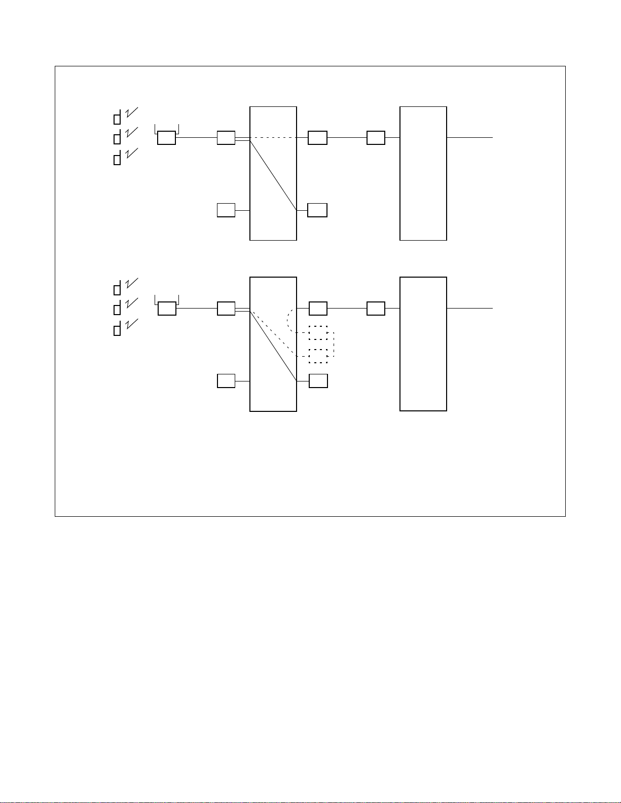
SYSTEM DESCRIPTION
(2) Adjunct Type [1]
PS
PS
PS
(3) Adjunct Type [2]
PS
PS
PS
ZT
ZT
WCS
CSI COT
DAT CSH
WCS
CSI DTI
LC
COT
DAT CSH
CCIS
*
PBX
LC
PBX
DTI
PS : Personal Station
ZT : Zone Transceiver
CSI : ZT Interface
CSH : ZT Handler
DAT : Digital Announcement Trunk
* : Virtual LC-COT Connection
Figure 2-1 System Diagram of WCS (2 of 2)
CHAPTER 2 ND-46248 (E)
Page 4
Revision 2.0
Page 23
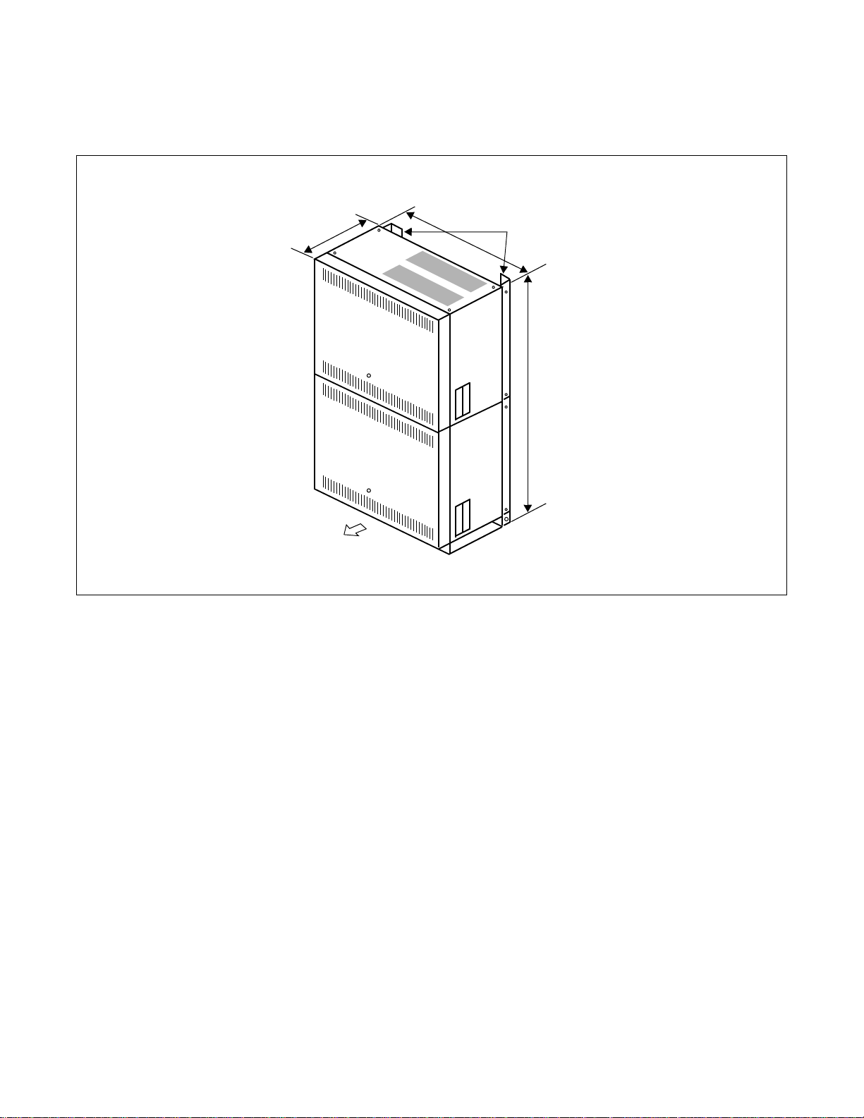
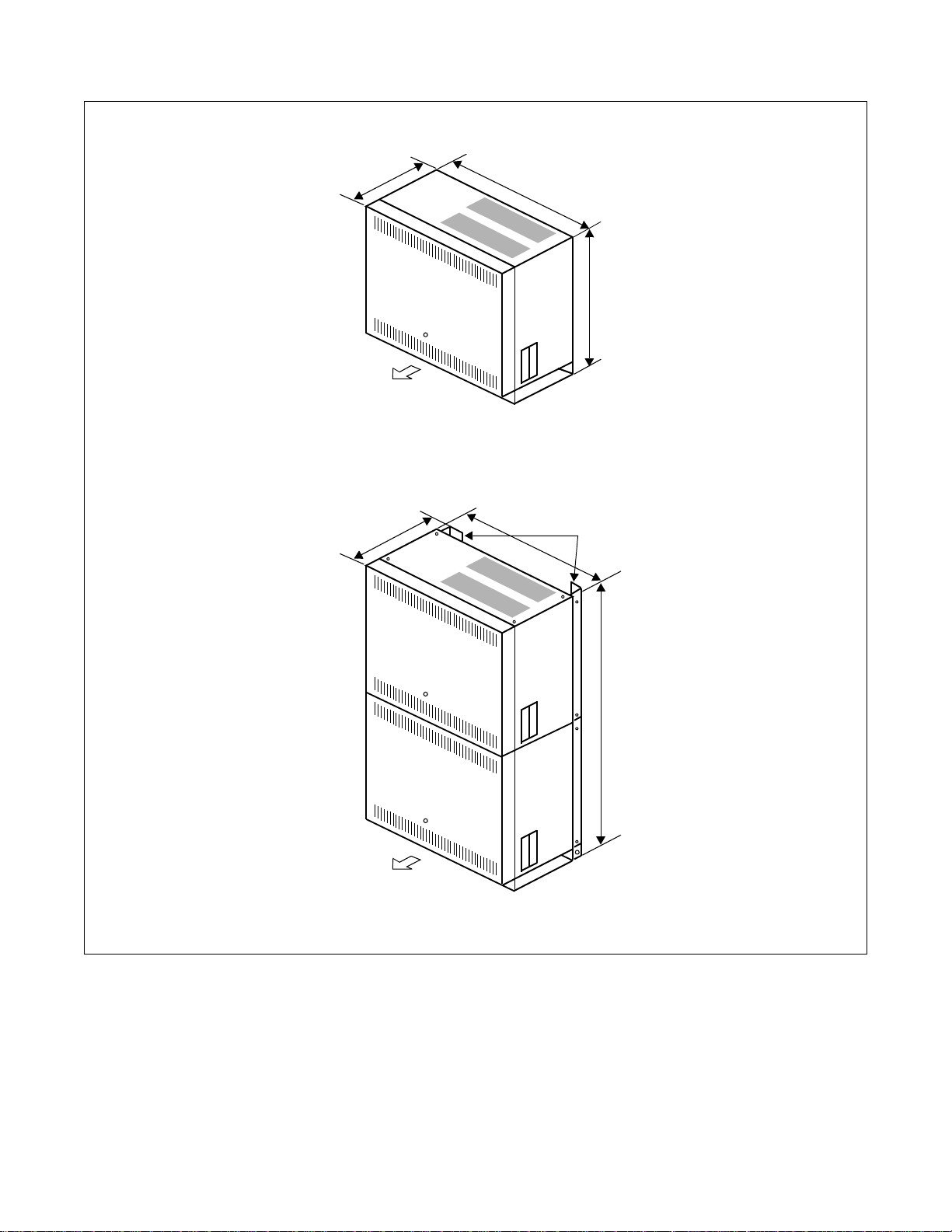
2.2 CSH
Examples of module configurations are shown in Figure 2-2.
(1) 1-PIM Configuration
SYSTEM DESCRIPTION
9.8/24.89
17/
PIM0
PWRM
FRONT
43.18
BASE
RACK PARTS
31/78.74
Figure 2-2 Module Configurations (1 of 4)
Unit : inches/centimeters
Note:
For WCS application, ICSVS PIMN-UB is required for each PIM.
ND-46248 (E) CHAPTER 2
Page 5
Revision 2.0
Page 24
SYSTEM DESCRIPTION
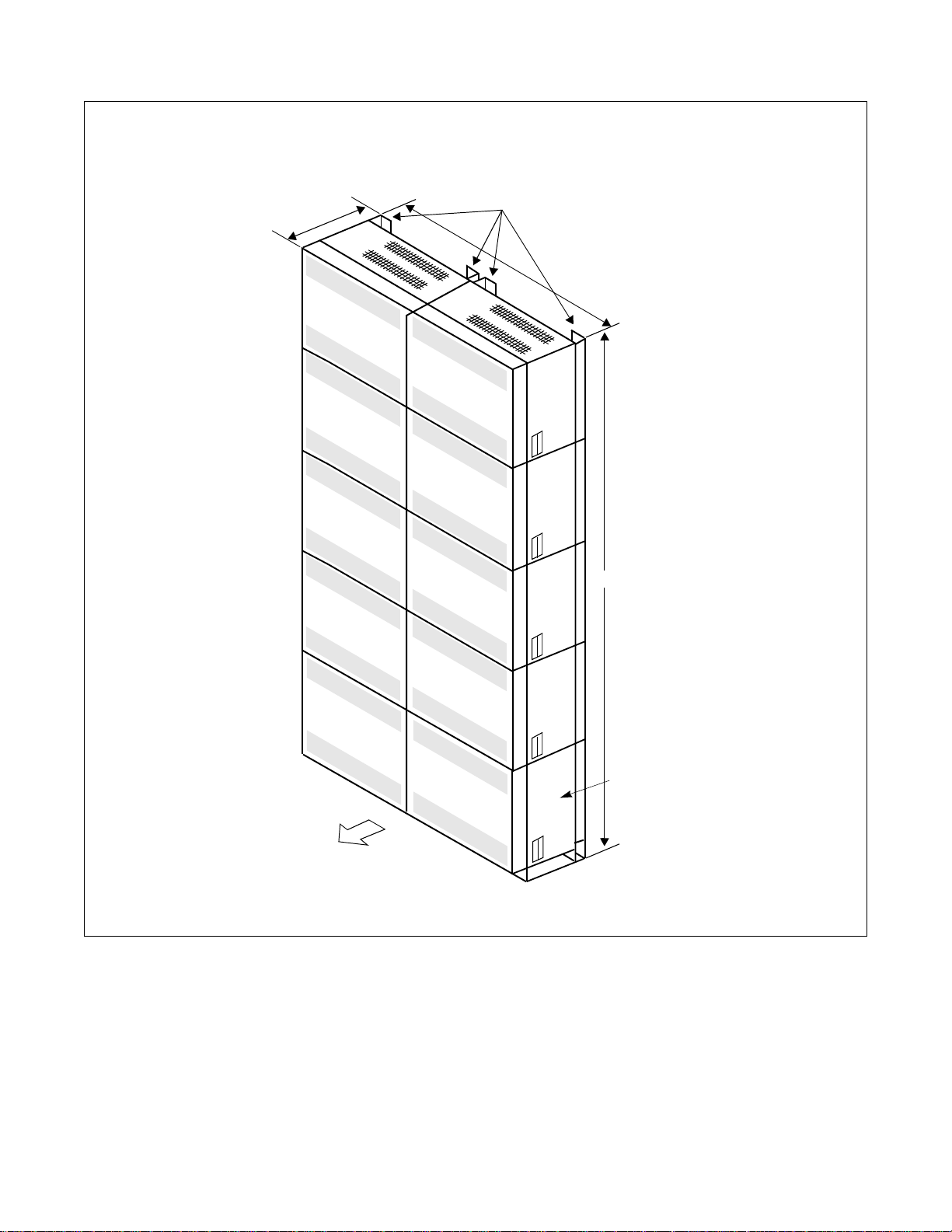
(2) Multiple PIM Configuration for NEAX2000 IVS
9.8/24.89
PIM3
PIM2
PIM1
PIM0
RACK PARTS
34/
86.36
PIM7
PIM6
77.2/196.09
PIM5
PWRM
FRONT
Figure 2-2 Module Configurations (2 of 4)
CHAPTER 2 ND-46248 (E)
Page 6
Revision 2.0
PIM4
Dummy PIM/
BATTM/MDFM
BASE
Unit : inches/centimeters
Page 25
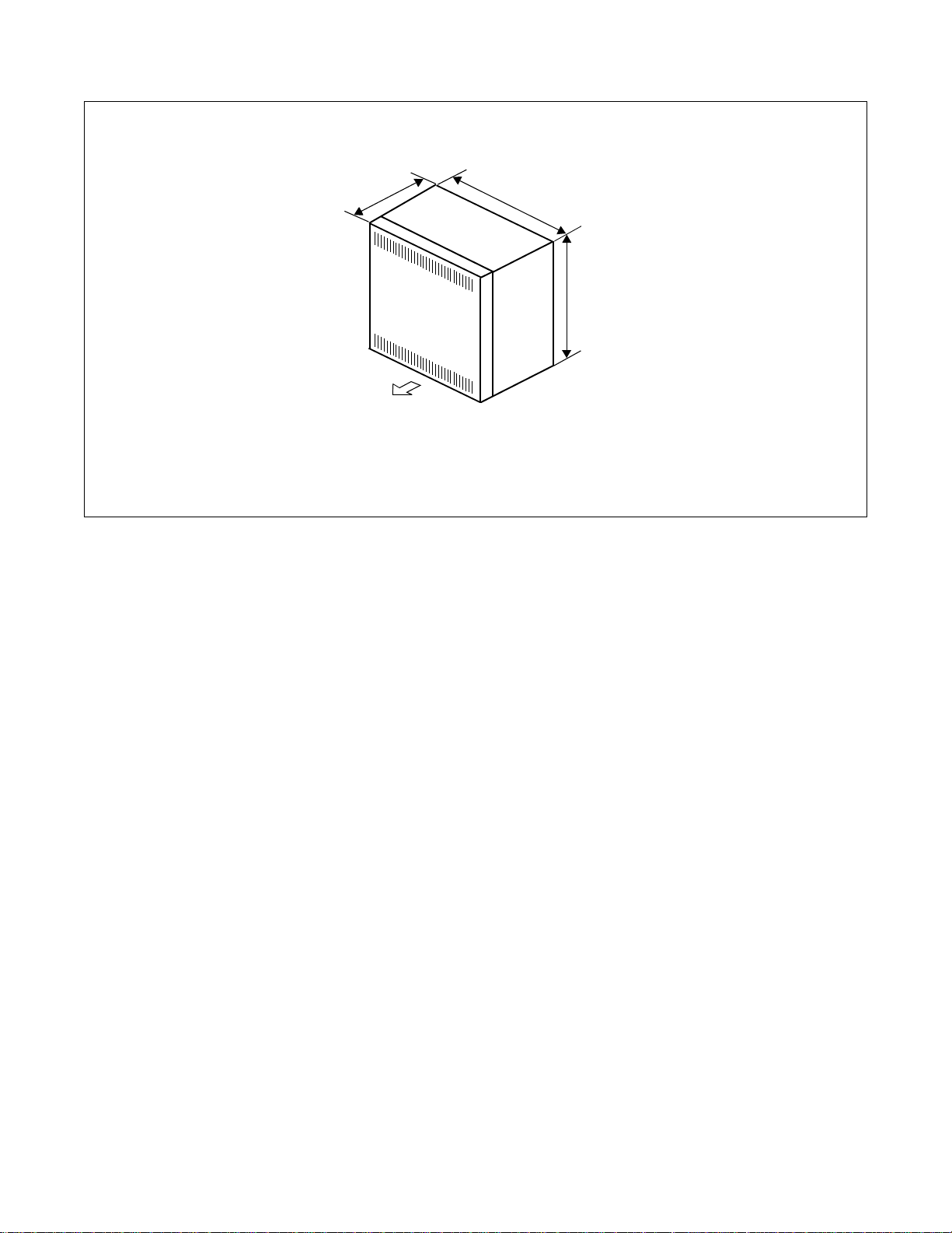
(3) Minimum C onfiguration for S mall Platform System
7.2/18.29
PIM0
SYSTEM DESCRIPTION
17/43.18
15.5/39.37
FRONT
(4) Maximum Configuration for Small Platform System
9.8/24.89
PIM0
PWRM
17/
BASE
43.18
RACK PARTS
29.3/74.42
FRONT
BASE
Figure 2-2 Module Configurations (3 of 4)
ND-46248 (E) CHAPTER 2
Unit : inches/centimeters
Page 7
Revision 2.0
Page 26
SYSTEM DESCRIPTION
(5) PIM Configuration for NEAX1000 IVS
8.521.59
13.8/35.05
PIM0
13.8/35.05
FRONT
Unit : inches/centimeters
Figure 2-2 Module Configurations (4 of 4)
CHAPTER 2 ND-46248 (E)
Page 8
Revision 2.0
Page 27

2.3 Outline of Circuit Cards
Table 2-1 shows the functional outline of circuit cards used for WCS.
SYSTEM DESCRIPTION
Table 2-1 Functional Outline of Circuit Card
CARD NAME
FUNCTIONAL
NAME
PN-SC03 CSH
PN-2CSIA CSI
PZ-PW91 PW91
PZ-PW86 PW86
PZ-PW00 PW00
PN-2DAT A DA T
FUNCTIONAL OUTLINE
ZT Handler card.
This card controls 4 CSI cards and i s equi pped with 8 circuits of D channel
signalling interface.
ZT Interface card.
This card is used to interface with ZT, based on ISDN S-interface.
Max. 2 ZTs can be connected with 1 CSI card.
-48 V power supply card for ZT.
A PW91 card provides -48V DC power for a maximum of 24 ZTs.
Max. 4 cards per PWRM.
Main Power Supply card.
This card provides power to all circuit cards mounted in the PIM.
1 card per PIM.
Power Supply card for ZT.
This card provides - 48 V DC power for a maximum of 2 ZTs and is mounted
in the LT/AP slot of PIM. Max 3 cards per system.
2-line Digital Announcement Trunk card.
This card is used for Announcement Service on the WCS.
Recording time: Max. 60 seconds.
PN-4COTB COT
PN-24DTA DTI
PN-30DTC DTI
PN-SC00 CCH
PN-SC01 DCH
4-line Central Office Trunk card.
This card is used for Adjunct Type 1 (LC-COT connection).
A 4 COT card is required per 4 PSs.
24 Channel Digital Trunk Interface card.
This card accommodates 24 c hann el PCM digit al li ne an d is used for CCIS
connection of Adjunct Type 2.
30 Channel Digital Trunk Interface card.
This card accommodates 30 c hannel digital PCM line and is used f or CCIS
connection of Adjunct Type 2, or for Multi-Site Roaming connection between the PBXs.
Common Channel Handler card.
This card controls common signalling channels of No.7 CCIS and is used for
CCIS connection of Adjunct Type 2.
D-Channel Handler card.
This card transmits /rece i v es cont rol signal s for Multi- Site Roaming c onnection between the PBXs.
ND-46248 (E) CHAPTER 2
Page 9
Revision 2.0
Page 28

SYSTEM DESCRIPTION
Table 2-1 Functional Outline of Circuit Card
CARD NAME
FUNCTIONAL
PN-AP00-A DBM
PWRU-A
Note:
Note
When the PWR U-A is equipped wi th the PZ- PW112 for NEAX1000 IVS, fo llow the f ollowing a ccommo-
–48V/50W
DC/DC PWR
dation limitations.
• Max. five 8DLC cards
or
• Max. four 8DLC cards and two 4DIT cards.
NAME
FUNCTIONAL OUTLINE
Data Base Module card for Multi-Site Roaming.
This card stores data related to Multi-Site Roaming.
1 card per system is required on each PBX in the network which provides
Multi-Site Roam ing.
Power Supply Unit for ZT. (for NEAX1000 IVS only)
This unit provides –48V DC power for a maximum of 6 ZTs, and i s mounted
in the vacant space at the lower left side of a Main Power Supply card. 1 unit
per PIM is available.
CHAPTER 2 ND-46248 (E)
Page 10
Revision 2.0
Page 29
3. SYSTEM SPECIFICATIONS
WIRE DIAMETER 26 AWG 24 AWG 22 AWG
POWER SUPPLY WCS LOCAL WCS LOCAL WCS LOCAL
DISTANCE
1500 ft.
(457 m)
2000 ft.
(609 m)
2000 ft.
(609 m)
3000 ft.
(914 m)
3000 ft.
(914 m)
3300 ft.
(1000 m)
3.1 System Specifications
DESCRIPTION SPECIFICATIONS REMARKS
Based on second generation wireless telephone
Wireless Protocol
system standard RCR-STD-28 FCC Sub part D,
UTAM complied
Distance between PBX and
ZT
SYSTEM DESCRIPTION
Table 2-2 System Specifications
Interface with a PBX
Note:
At Nomina l Voltage of -48V.
Analog station line interface For Adjunct Type [1]
TI or EI interface with CCIS For Adjunct Type [2]
ND-46248 (E) CHAPTER 2
Page 11
Revision 2.0
Page 30

SYSTEM DESCRIPTION
3.2 System Capacity
Table 2-3 NEAX2000 IVS WCS System Capacity
CAPACITY
DESCRIPTION
Number of PS
Note 1
Number of simultaneous
connections for PS
Note 1
Integrated Type
168
(250)
Note 2
152
(159)
Note 2
Type1
(LC-COT)
(234)
Adjunct Type
248
219
Note 2
Type2
(CCIS)
162
(232)
146
(153)
Number of B channels per
ZT (Simultaneous
333
connections per ZT)
Number of ZT 96 96 80
Number of ZT per CSI 2 2 2
Number of Calling Areas 32 32 32
Number of ZT per Calling
Area
96 96 80
Number of CSI 48 48 40
REMARKS
Note 2
Note 2
Max. 12 per PIM
(No local power
supplied)
Number of CSH 12 12 10
Note 1:
When Multi-Site Roaming i s pr o vided, “Nu mber of PS ” and “Number of s imultaneo us connecti ons for
PS” equal the sum of the Number of the Home PS and the Visitor PS.
Note 2:
The capacity of th e PSs can be e xpanded to the numbe r in par entheses. For details, refer to nex t section.
CHAPTER 2 ND-46248 (E)
Page 12 Addendum-001
Revision 2.1 MARCH, 1999
Page 31

Table 2-4 Small Platform System WCS System Capacity
CAPACITY
SYSTEM DESCRIPTION
DESCRIPTION
Number of PS
Note 1
Number of simultaneous
Type 1
(PW00)
Type 2
(PW91)
Type 1
(PW00)
Integrated Type
168
(250)
Note 2
168
(250)
Note 2
18
(LC-COT) (CCIS)
4COT: 32
8COT: 64
4COT: 36
8COT: 64
4COT: 12
8COT: 16
Adjunct Type
162
(232)
162
(232)
18
connections for PS
Note 1
Type 2
(PW91)
Number of B channel per ZT
(Simultaneous connections per ZT)
Type 1
(PW00)
48
333
666
4COT: 24
8COT: 32
48
Number of ZT
Type 2
(PW91)
16 16 16
Number of ZT per CSI 2 2 2
Type 1
(PW00)
666
Calling Areas
Type 2
(PW91)
16 16 16
REMARKS
Note 2
Note 2
ZT per Calling Area
Number of CSI
Number of CSH
Note 1:
When Multi-Site Roaming i s pr o vided, “Number of PS” and “Nu mber of simult aneous conne ctions fo r
PS” equal the su m of the Number of the Home PS and the Visitor PS.
Note 2:
The capacity of th e PSs can be e xpanded to the numbe r in par entheses. For details, refer to nex t section.
Type 1
(PW00)
Type 2
(PW91)
Type 1
(PW00)
Type 2
(PW91)
Type 1
(PW00)
Type 2
(PW91)
666
16 16 16
333
888
111
222
ND-46248 (E) CHAPTER 2
Addendum-001 Page 13
MARCH, 1999 Revision 2.1
Page 32

SYSTEM DESCRIPTION
Table 2-5 NEAX1000 IVS WCS System Capacity (1 PIM Configuration)
CAPACITY
DESCRIPTION
Number of PS
Note 1
Type 3 (PWRU-A)
Number of simultaneous
connections for PS
Note 1
Type 3 (PWRU-A) 18
Number of B channel per ZT
(Simultaneous connections per ZT)
Integrated Type
Type 1 (PW00)
Type 2* (Local)
168
(250)
168
(250)
168
(250)
Type 1 (PW00) 12
Type 2* (Local) 30
333
Note 2
Note 2
Note 2
(LC-COT) (CCIS)
4COT: 16
8COT: 32
4COT: 24
8COT: 40
4COT: 24
8COT: 40
4COT: 6
8COT: 8
4COT: 16
8COT: 24
4COT: 16
8COT: 18
Adjunct Type
162
(232)
162
(232)
162
(232)
Type 1 (PW00) 4 4 2
Number of ZT
Type 2* (Local) 10 10 8
Type 3 (PWRU-A) 6 6 6
Number of ZT per CSI 2 2 2
Note 2
Note 2
Note 2
6
24
18
Type 1 (PW00) 4 4 2
Calling Areas
Type 2* (Local) 10 10 8
Type 3 (PWRU-A) 6 6 6
Type 1 (PW00) 4 4 2
ZT per Calling Area
Type 2* (Local) 10 10 8
Type 3 (PWRU-A) 6 6 6
Type 1 (PW00) 2 2 1
Number of CSI
Type 2* (Local) 5 5 4
Type 3 (PWRU-A) 3 3 3
Type 1 (PW00) 1 1 1
Number of CSH
Type 2* (Local) 2 2 1
Type 3 (PWRU-A) 1 1 1
*–48V power is provided to ZT by optional Local AC/DC power
Note 1:
When Multi-Site Roaming i s pr o vided, “Number of PS” and “Nu mber of simult aneous conne ctions fo r
PS” equal the su m of the Number of the Home PS and the Visitor PS.
Note 2:
The capacity of th e PSs can be e xpanded to the numbe r in par entheses. For details, refer to nex t section.
CHAPTER 2 ND-46248 (E)
Page 14 Addendum-001
Revision 2.1 MARCH, 1999
Page 33

SYSTEM DESCRIPTION
Table 2-6 NEAX1000 IVS WCS System Capacity (2 PIM Configuration)
CAPACITY
DESCRIPTION
Number of PS
Note 1
Type 3 (PWRU-A)
Number of simultaneous
connections for PS
Note 1
Type 3 (PWRU-A) 36
Number of B channel per ZT
(Simultaneous connections per ZT)
Integrated Type
Type 1 (PW00)
Type 2* (Local)
168
(250)
168
(250)
168
(250)
Type 1 (PW00) 24
Type 2* (Local) 72
333
Note 2
Note 2
Note 2
(LC-COT) (CCIS)
4COT: 48
8COT: 80
4COT: 56
8COT: 88
4COT: 56
8COT: 88
4COT: 18
8COT: 24
4COT: 32
8COT: 40
4COT: 32
8COT: 36
Adjunct Type
162
(232)
162
(232)
162
(242)
24
66
36
Type 1 (PW00) 8 8 8
Number of ZT
Type 2* (Local) 24 24 22
Type 3 (PWRU-A) 12 12 12
Number of ZT per CSI 2 2 2
Note 2
Note 2
Note 2
Type 1 (PW00) 8 8 8
Calling Areas
Type 2* (Local) 24 24 22
Type 3 (PWRU-A) 12 12 12
Type 1 (PW00) 8 8 8
ZT per Calling Area
Type 2* (Local) 24 24 22
Type 3 (PWRU-A) 12 12 12
Type 1 (PW00) 4 4 4
Number of CSI
Type 2* (Local) 12 12 11
Type 3 (PWRU-A) 6 6 6
Type 1 (PW00) 1 1 1
Number of CSH
Type 2* (Local) 3 3 3
Type 3 (PWRU-A) 2 2 2
* –48V power is provided to ZT by optional Local AC/DC power.
Note 1:
When Multi-Site Roaming i s pr o vided, “Number of PS” and “Nu mber of simult aneous conne ctions fo r
PS” equal the su m of the Number of the Home PS and the Visitor PS.
Note 2:
The capacity of th e PSs can be e xpanded to the numbe r in par entheses. For details, refer to nex t section.
ND-46248 (E) CHAPTER 2
Addendum-001 Page 15
MARCH, 1999 Revision 2.1
Page 34

SYSTEM DESCRIPTION
3.3 Expanding PS Capacity
The maximum number of Wireless PS stations has been expanded from 168 to 250 when an Integrated type
system is being used. Pr eviously, ea ch PS line reduced the c apacity of CM10 b y three port s [One port fo r CM1C
and two ports for CM10 (one Virtual Trunk and one Virtual Station)]. With a CPXX-C card and 1900 Series
Release 2 software, eac h PS line reduc es the cap acity of CM10 b y only two por ts. A new memory a rea has bee n
added for CM1C and this command no longer impacts the memory capacity of CM10.
To perform backups of the new memory area (save and load), an updated version of MATWorX-32 (Version
2.6 or higher) with the “MP4” file extension type must be used. (MP4 = Areas 1-6).
To expand the system capacity for the PS, the CP00-C/CP03-C card and 1900 Series Release 2 or later MP
program are required. The table below shows the MP program upgrading procedure.
UPGRADE FROM UPGRADE TO UPGRADING PRO CEDURE
MP Program:
1900 Series or earlier
MP Program:
1900 Series Release 2 or
later
MP Card: CP00-B
CP03
MP Card: CP00-C
CP03-C
MP Program:
1900 Series or earlier
MP Program:
1900 Series Release 2 or
later
MP Card: CP00-C
CP03-C
MP Card: CP00-C
CP03-C
1D21--Default is “None.” No PS-ID. Must be reassigned.
1D15--Default is “15.” Mode 1.
1D01--Default is “None.” No Subline.
1202--Default is “1515.” Service Restriction Class A/B.
1216--Default is “None.” Must be reassigned.
1D20--Download the PS’s. Must be executed.
Note:
The Down does not need to be successful, but Command 1D20 must be executed.
(1) Save office data (MP 3 area) of CP00-B/CP03 by
MAT.
(2) Exchange CP00-B/CP03 to the CP00-C/CP03-C.
(3) Load 1900 Series Release 2 MP program to CP00-
C/CP03-C.
(4) Clear all office data by CM00 1st: 1, 2nd: CCC.
(5) Load saved office data of CP00-B/CP03.
(1) Load 1900 Series Release 2 MP program.
(2) Clear office data for new memo ry area by CM00
1st: 3, 2nd: CCC.
The maximum number of PSs that can be added to the system depends on the number of existing PSs in the
system before upgrading. The following number of ports are required to provide a PS.
Before system upgrade: 3 ports per PS (for the PS, the virtual LC and the virtual COT)
After system upgrade: 2 ports per PS (for the virtual LC and the virtual COT)
CHAPTER 2 ND-46248 (E)
Page 15-1 Addendum-001
Revision 2.1 MARCH, 1999
Page 35

The table below shows the example of the system capacity on NEAX2000 IVS.
SYSTEM DESCRIPTION
INSTALLING
CONDITION
When upgrading
a system
When installing
a new system
Note:
When the 168 PSs have been provided in the system, and more PSs are required, the all existing PSs’
office da ta must be clear e d by the CM1C individual ly and r e-ente r ed. By this means, up to 250 PSs can
be provided.
For example, if 50 PSs will be added, 100 existing PSs’ office data must be cleared and re-entered.
Existing 168 PSs 68 PSs (3 ports per PS)
Adding PSs 50 PSs (2 ports per PS)
EXISTING PS ADDING PS CS D
168
100
50
0
0
100
175
168
250
0
1
1
1
1
1
100 PSs (2 ports per PS) Office data must be cleared and re-entered.
term
168
REQUIRED PORTS REMARKS
0
4
4
511
511
511
511
4
511
Note
ND-46248 (E) CHAPTER 2
Addendum-001 Page 15-2
MARCH, 1999 Revision 2.1
Page 36

SYSTEM DESCRIPTION
3.4 Time Slot Assignment Conditions
3.4.1 Time Slots for CSH Card
As shown in Figure 2-3, the CSH card uses the time slot on the same highway as the other application cards such
as [PN-AP00 (AP00)/PN-ME00 (EXTMEM)]. Therefore, the total number of time slots for all CSH card must
be less than 128 time slots including all other application cards.
FOR L/T CARDS + DTI CARDS : MAX. 512 TIME SLOTS PER SYSTEM (NEAX2000 IVS)
FOR L/T CARDS : MAX. 512 TIME SLOTS PER SYSTEM (NEAX2000 IVS)
TDSW (1024 TIME SLOTS)
MAX. 72 TIME SLOTS PER SYSTEM (Small Platform System)
MAX. 48 TIME SLOTS PER SYSTEM (NEAX1000 IVS)
MAX. 72 TIME SLOTS PER SYSTEM (Small Platform System)
MAX. 48 TIME SLOTS PER SYSTEM (NEAX1000 IVS)
FP0
FP1
FP2
FP3
DTI
DTC
CCH
CSH
AP00
MAX.128 TIME SLOTS
MAX.128 TIME SLOTS
MAX.128 TIME SLOTS
MAX.128 TIME SLOTS
MAX.24 TIME SLOTS / CARD
MAX.31 TIME SLOTS / CARD
1 TIME SLOT / CARD
4 TIME SLOTS / CARD
1 TIME SLOT / CARD
EXTMEM
FOR AP CARDS : MAX. 128 TIME SLOTS PER SYSTEM
1 TIME SLOT / CARD
•
•
•
•
Figure 2-3 Accommodation of CSH into TDSW
3.4.2 Time Slots for CSI Card
The CSI (PN-2CSIA) card uses seven (7) time slots per card.
CHAPTER 2 ND-46248 (E)
Page 16 Addendum-001
Revision 2.1 MARCH, 1999
•
•
•
•
Page 37

SYSTEM DESCRIPTION
4. OUTLINE OF MULTI-SITE ROAMING
4.1 Functional Outline
The PBX supports the JT-Q931a protocol and JT-11582 for signaling at Q-reference point between PBXs on
the private network. By supporting this protocol, the PSs can be used in any Calling Area on the pr ivate network.
When a PS roams over the adjoining PBX’s Calling Area;
PBX A
Dp Channel Private Line
(JT-Q931a)
ZT ZT
ROAMING
PS PS
When a PS roams over other Calling Area through the relaying office;
PBX A PBX B
Dp Channel
Private Line
(JT-Q931a) (JT-Q931a)
PBX C
Dp Channel
Private Line
PBX B
ZT
PS PS
Note:
ZT
ROAMING
Also to the relaying office (PBX C), the installation and
ZT
the data assignment for Multi-Site Roaming are required.
Figure 2-4 Functional Outline of Multi-Site Roaming
ND-46248 (E) CHAPTER 2
Page 17
Revision 2.0
Page 38

SYSTEM DESCRIPTION
4.2 Multi-Site Roaming System Configuration
1. System Configuration
The following figure shows the system configuration for Multi-Site Roaming.
HOME PBX
PUBLIC
NETWORK
VISITOR PBX
PS
PS
CSI
ZT
TRK
VIRTUAL
VIRTUAL
CSH
DTI
PLO
VIRTUAL
VIRTUAL
LC
TRK
LC
TRK
Dp Channel Private Line
(JT-Q931-a)
VIRTUAL
LC
VIRTUAL
TRK
CSH
VIRTUAL
LC
VIRTUAL
TRK
TRK
CSI
ZT
DTI
PS
PLO
PS
DCH
DBM
Roaming
The equipment in this square is required for Multi-Site Roaming.
Figure 2-5 System Configuration of Multi-Site Roaming
CHAPTER 2 ND-46248 (E)
Page 18
Revision 2.0
DCH
DBM
Page 39

SYSTEM DESCRIPTION
2. Words definition for Multi-Site Roaming
Virtual LC: Virtual LC exists only on the system data, provided via non-hardware supported
LEN’s. The Virt ua l LC m us t b e as si g ned by th e sy st em da ta p rog ra mm i ng f o r o perating Home PSs and Visitor PSs used for Multi-Site Roaming, together with the
Virtual TRK.
Virtual TRK: Virtual TRK (trunk) exists only on the system data, provided via non-hardware
supported LENs. The Virtual TRK must be assigned by the system data programming for operati ng Home PSs and Visitor PSs used f or Multi-Sit e Roaming, toge ther with the Virtual LC.
Individual PS Number: Individual PS Number is assigned to a PS to identify the PS on the Roaming Net-
work. It must be an unique number in the network.
Network ID Method: Network ID Method is one Method to operate Multi-Sit e Roaming. A Roaming PS
must have two SYS-ID on the Network ID Method. One is Main SYS-ID for Home
PBX, and another is Network ID for Roaming Network. The Network ID is used
to define whether the PS can operate under the control of PBXs on the Roaming
Network. The network ID must be the same for all PBXs within the same netw ork.
V isi tor PBX: When a PS leaves cont rol of a PBX to which it belong s origi nally, and is operating
in a zone of another PBX, the PBX is called “Visitor PBX”.
V isi tor PS: When a PS lea v es c ontrol of a PBX to whi ch it bel ongs or igina lly, and is operating
in a zone of another PBX, the PS is called “Visitor PS”.
Home PBX: Home PBX is a PBX to which a PS ordinarily belongs.
Home PBX ID: Home PBX ID is a unique number to identify the PBX on the Roaming Network.
Home PS: When a PS operates unde r control of a PBX to whic h the PS origina lly belongs, th e
PS is called “Home PS”.
Roaming Number: Roaming Number is assigned to a Visitor PS temporarily, when the PS is roaming
to a Visitor PBX. The Ac tual Ro aming Numb er is Virtual LC Sta tion n umbe r as-
signed as a Pilot Station of Station Hunting Group on the Visitor PBX.
HLR: Home Location Register. A database to store the location registration data of the
Home PS.
VLR: Visitor Location Registe r. A database to s tore the locat ion regist ration data of the
Visitor PS temporarily, when the Visitor PS is in the zone of anoth er PBX.
ND-46248 (E) CHAPTER 2
Page 19
Revision 2.0
Page 40

SYSTEM DESCRIPTION
4.3 Summary of Multi-Site Roaming System Operation
1. Location Registration of PS
a. In the zone of the Visitor PBX, the Visitor PS requests the Visitor PBX for loc ation registration of its
own.
b. The Visitor PBX analyses the number sent from the Visitor PS, and detects the Home PBX of Visito r
PS.
c. The Visitor PBX inquires of the Home PBX about the profiles; various data which is assigned to the
PS for the operation as a Visitor PS.
d. The Home PBX analyses the number included with the inquiry, and detects whether the Visitor PS is
one of the Home PS of its own.
If the Visitor PS is detected as a PS wh ich belon gs to anoth er PBX , the P BX fo rward s the in qu iry to
the corresponding route.
e. If the Visitor PS is detected as a Home PS, the Home PBX sends the Visitor PS profiles to the Visitor
PBX.
f. The Visitor PBX confirms the profiles sent from the Home PBX, and determines the Roaming Number
for the Visitor PS.
The actual Roaming Number is Virtual LC Station number assigne d as a Pilot Station of Station Hunt-
ing Group on the Visitor PBX.
g. The Visitor PBX registers the profile data of th e Visitor PS to the VLR.
h. Then notifies the c ompleti on of r e gist rati on to t he Home PBX. Th e noti f ica tion c ontai ns the Roaming
Number determined.
i. The Home PBX receives the notification, and stores the Roaming Number to the HLR.
VISITOR PBX
(g) Registration to VLR
(
a
)
R
e
(f) Confirming profiles
q
u
e
s
t
i
n
g
l
o
c
a
t
i
o
n
r
VLR
e
g
i
s
t
r
a
t
i
o
n
HLR
HOME PBX
(i) Registration to HLR (h)
(d) Analyse the inquiry
Q931a Digital Line
Notification completion of registration
(e) Sending profiles
(c) Profiles inquiry
(b) Interpreting Home PBX
Figure 2-6 Location Registration System Operation
CHAPTER 2 ND-46248 (E)
Page 20
Revision 2.0
VISITOR
PS
Page 41

SYSTEM DESCRIPTION
2. Call Termination to Visitor PS
a. The Home PBX receives the call to a Home PS from another PBX.
b. The Home PBX refers the HLR information of the PS.
c. From the Roaming Number contained in the HLR information, the Home PBX detects whether the
Home PS is roaming.
d. The Home PBX inquires of the Visitor PBX about the call termination to the Visitor PS. The inquiry
contains the roaming data of the Visitor PS, such as Roaming Number and Individual PS Number.
e. The Visitor PBX analyses the Roaming Number, and refers to the VLR information of the Visitor PS
in accordance with the Individual PS Number.
f. The Visitor PBX confirms the VLR informatio n.
g. The Visitor PBX terminates the call to the Visitor PS.
X
B
P
r
e
h
t
HOME PBX
C
)
a
(
o
n
a
m
o
r
f
l
l
a
Q931a Digital Line
VISITOR PBX
(b) Referring HLR
HLR
(c) Interpreting the
location of the PS
(d) Call termination inquiry
(
Figure 2-7 Call Termination System Operation
(e) Referring VLR
VLR
(f) Confirming VLR
g) Call Termination
VISITOR
PS
ND-46248 (E) CHAPTER 2
Page 21
Revision 2.0
Page 42

SYSTEM DESCRIPTION
4.4 Multi-Site Roaming System Condition
1. Trunk
• Multi-Site Roaming can be e x ec uted onl y on tr unk conne ction b etween PBXs based on J T-Q931a pro-
tocol.
• To each trunk route of JT-Q931a trunks, it can be specif ied whethe r Multi-Si te Roa ming is pr ov ided o r
not.
• The JT-Q931a trunks can be used by Single Line Telephone stations and Dterm stat ions for or iginating
or receiving calls as same as common trunks.
2. Data Base Module
• An AP00 card for Data Base Module (DBM) is required per PBX.
The AP00 card can not be used as Bil ling Ap plica tion Proce ssor (for S MDR, MCI, PMS or Hote l/Motel features ).
• System data stored in the memory of the AP00 card can be saved, loaded and verified from a MAT.
(Memory Area No.:A, Memory Address: 00900-10870, File Extension: DMA)
• A Roaming network can consist of maximum 512 PBXs.
• Visitor Location Register (VLR) information for maximum 512 Visitor PSs can be recorded to a sys-
tem.
VLR information is the various information of Visitor PS and is made in the memory of AP00 on the
Visitor PBX when the PS is roaming.
When the VLR information exceeds for more than 512 PSs, AP00 overwrites the oldest VLR information.
3. Home PS/Visito r PS
• To use the PSs fo r Multi-Site Roaming, the fo llowing must be assigned to the PSs.
- SYS-ID; SYS-ID of Home PBX.
- PS-ID; An unique number for identifying the PS.
- Individual PS Number; The same number with the Home PBX ID.
- Extension Number; The same number with the Individual PS Number.
- Network ID; It must be assigned when the Roaming Network adopts Network ID Methods.
- Home PBX ID; An unique number for identifying the PBX on the Roaming Network.
CHAPTER 2 ND-46248 (E)
Page 22
Revision 2.0
Page 43

CHAPTER 3 INSTALLATION
1. GENERAL
This chapter details the installation procedure to provide WCS functions to the PBX.
2. PRECAUTI O N IN HANDLING
The installer must wear the gr ounded wrist str ap to protect the cir cuit card from stati c electrici ty, when handling
cards, and the installer must engage in the work on a grounded conductive work surface.
• WHEN PLUGGING/UNPLUGGING A CIRCUIT CARD
PBX
• WHEN HOLDING A CIRCUIT CARD
FRAME GROUND SCREW
WRIST STRAP
CONNECT THE GROUND WIRE TO THE
FRAME EARTH OF THE EQUIPMENT.
NEVER TOUCH THE COMPONENTS OR
SOLDERED SURFACE W IT H BARE HANDS.
CARD FRONT
Figure 3-1 Static Electricity Precautions (1 of 2)
ND-46248 (E) CHAPTER 3
Page 23
Revision 2.0
Page 44

INSTALLATION
• WHEN SETTING SWITCHES ON A CIRCUIT CARD
• WHEN CARRYING A CIRCUIT CARD
CIRCUIT
CARD
WEAR A WRIST STRA P AN D PERFORM
THE WORK ON A GROUNDED
CONDUCTIVE WORK SURFACE.
CIRCUIT
CARD
CONDUCTIVE
POLYETHYLENE
BAG
WHEN CARRYING A CIRCUIT
CARD AROUND, KEEP THE
CARD IN THE CONDUCTIVE
POLYETHYLENE BAG.
Figure 3-1 Static Electricity Precautions (2 of 2)
The mark shown below i s a tt ac hed to the sheet for t he wo rk in which circuit cards ar e handled. When engaging
in such work, the installer must be careful not to cause damage by static electricity.
ATTENTION
Contents
Static Sensitive
Handling
Precautions Required
CHAPTER 3 ND-46248 (E)
Page 24
Revision 2.0
Page 45

INSTALLATION
CAUTION
You must hold the card name label area, when plugging or unplugging the circuit card. If you touch another
area, you may be exposed to hazardous voltages.
PBX
NEVER TOUCH THE COMPONENTS
OR SOLDERED SURFAC E W ITH
BARE HANDS.
CARD FRONT
ND-46248 (E) CHAPTER 3
Page 25
Revision 2.0
Page 46

INSTALLATION
3. EQUIPMENT AND CABLES
Table 3-1 below shows the equipment required when providing the WCS interface to the system.
Table 3-1 Required Equipment for WCS
EQUIPMENT DESCRIPTION QUANTITY REMARKS
(1) For Integrated Type/Adjunct Type
• ICS VS PIMN-UB
- SN1273 PIMN-A
- PZ-PW86
- PWR CNT (CA-A)
- AC CORD-B-U
- RACK PARTS
• POWER MODULE-UB
- SN1302 PWRMC-A
- PWR CNT CA-B
- RACK PARTS
- BATT BRACKET
ASSEM
- BATT CA-PSI
- AC CORD (A)
• ICS VS BASE/TOP-UB
- SN1317 BASEG-A
- AC CORD (A)
• PZ-PW91 W/CA
- PZ-PW91
- PWR-1.7 CA-WA
- AC CORD-B-U1
-PWR CA-A
Port Interface Module for WCS N N: 1-8
Power Module for PW91 card 1
Base unit and top cover N N: 1-2
- 48V Power supply card for ZT N N: 1-4
• PN-PW00
• PWRU-A
- 48V Power supply card for ZT
(for Small Platform System/1000IVS)
- 48V Power supply card for ZT
(for 1000IVS)
NN: 1-3
NN: 1-2
• PN-2CSIA ZT Interface card → 2 ZT/card N N: 1-48
• PN-SC03 8CSH (AP) ZT Handler card → 4 2CSIA/ card N N: 1-12
• PN-2DATA (DAT)
Digital Announcement Trunk N N: As required for
Announcement Service
When providing Roaming Service
• PN-24DTA-A/
24/30 channels DTI card N N: 1-5
30DTC/30DTC-A (DTI)
• PN-SC01 (DCH) D-channel Handler card N N: 1-5
• PN-AP00-A (DBM) Roaming Data Base Module card 1
• ZT Zone Transceiver N N: 1-96
• PS Personal Station N N: 1-168
CHAPTER 3 ND-46248 (E)
Page 26
Revision 2.0
Page 47

INSTALLATION
Table 3-1 Required Equipment for WCS (Continued)
EQUIPMENT DESCRIPTION QUANTITY REMARKS
(2) For Adjunct Type [1]
The equipment above (1) except the PS are required with the following:
• PN-4COTB (COT) Central Office Trunk N N: Number of PS/4
• PS Personal Station N N: 1-248
(3) For Adjunct Type [2]
The equipment above (1) except the PS are required with the following:
• PN-24DTA-A/
24 channels DTI card N N: 1-5
30DTC/30DTC- (DTI)
• PN-SC00 (CCH) Common Channel Handler card N N: 1-4
• PS Personal Station N N: 1-162
ND-46248 (E) CHAPTER 3
Page 27
Revision 2.0
Page 48

INSTALLATION
4. INSTALLATION PROCEDURE
Perform the installation of the equipment according to the procedure shown in Figure 3-2.
START
SECURING OF BASE
AC POWER CABLE WIRING
MOUNTING PWRM/PIM
MOUNTING PWR CARD
CONNECTION OF POWER
CABLES
CONNECTION OF BUS
CABLES
Refer to IVS Installation
Procedure Manual.
SEE SECTION 4.1.
SEE SECTION 4.2.
SEE SECTION 4.3.
SEE SECTION 4.4.
SEE SECTION 4.5.
SWITCH SETTINGS OF
CIRCUIT CARDS
MOUNTING FP CARD
A
Figure 3-2 Installation Procedure (1 of 2)
CHAPTER 3 ND-46248 (E)
Page 28
Revision 2.0
SEE SECTION 4.6.
SEE SECTION 4.7.
Page 49

INSTALLATION
A
MOUNTING CSI CARD
MOUNTING CSH CARD
CONNECTION OF BATTERY SEE SECTION 4.11.
END
SEE SECTION 4.8.
SEE SECTION 4.9.
SEE SECTION 4.10.CONNECTION OF ZT
Figure 3-2 Installation Procedure (2 of 2)
ND-46248 (E) CHAPTER 3
Page 29
Revision 2.0
Page 50

INSTALLATION
4.1 AC Power Cable Wiring
STEP 1: Secure the BASE to the floor. For details, refer to the IVS Installation Procedure Manual.
STEP 2: Secure the AC CORD-B-U/AC CORD-B-U1 cables to the FG, NEUTRAL and LINE terminals on
the BASE as shown in Figure 3-3 and 3-4.
PUSH : INSERT THE AC CORD
PULL : FIXED THE AC CORD
CORD BUSH
(PROVIDED WITH BASE)
A
C
T
C
PIM
O
O
R
P
P
I
D
W
M
-
8
/
B
P
6
-
I
U
M
C
/
U
A
9
1
R
1
D
C
A
I
N
R
D
Note:
BASE
FG CABLE
(PROVIDED WITH BASE)
AC POWER
KNOCK OUT HOLE
SUPPLEMENTARY GROUND
(TO COLD WATER PIPE, ETC.)
Figure 3-3 Screwing AC CORD-B-U to Terminals
AC CORD - B - U ... to PW86 card in each PIM
AC CORD - B - U1 ... to PW91 card in Power Module
TO 120/240 V AC
SOURCE POWER
3P AC POWER CABLE
(PROVIDED WITH BAS E)
CHAPTER 3 ND-46248 (E)
Page 30
Revision 2.0
Page 51

INSTALLATION
AC CORD-B-U
TO PW91 CARD IN PWRM
BASE
FG NEUTRAL LINE
AC CORD-B-U
TO PW86 CARD IN PIM
Figure 3-4 Wiring AC CORD-B to Terminals
STEP 3: The AC CORD (A) and the FG Cable are pre-installed with the BASE.
AC CORD (A)
WARNING:
For configurat ions with 3 or more PIMs plus one Power Module, secur e the ad ditional AC CORD
(A) to the BASE as shown in Figure 3-5.
ND-46248 (E) CHAPTER 3
Page 31
Revision 2.0
Page 52

INSTALLATION
BASE
Additional AC CORD (A)
AC CORD (A)
(Provided with
BASE)
FG NEUTRAL LINE
Figure 3-5 Wiring AC CORD (A) to Terminals
CHAPTER 3 ND-46248 (E)
Page 32
Revision 2.0
Page 53

INSTALLATION
4.2 Mounting PWRM/PIM
STEP 4: Mount the PWRM on the B A SE, and c onnect them to gether using th ree (3 ) bolt s (pr ov ided) as shown
in Figure 3-6.
Note:
The PWRM must be mounted over the 4 RACK PART screws previously installed.
PWRM
Note
B
F
R
O
N
T
Note:
The Battery Module (B ATT M) and/or the MDF Module (MDFM) can be installed in the same manner as the PWRM.
Figure 3-6 Mounting of PWRM
STEP 5: Mount and connect the PIM on the PWRM with three bolts provided.
When the system is a multiple-PIM configuration, connect PIMs to each other in the same manner.
ND-46248 (E) CHAPTER 3
A
S
E
Page 33
Revision 2.0
Page 54

INSTALLATION
4.3 Mounting PWR Card
4.3.1 Mounting PW91 Card
Mount the PW91 card into the Power Module (PWRM) as shown in Figure 3-7.
PWRM
PW91
Figure 3-7 Mounting PW91 Card into PWRM (Power Module Unit)
CHAPTER 3 ND-46248 (E)
Page 34
Revision 2.0
Page 55

4.3.2 Mounting PW00 Card
1. Small Platform System
Mount the PW00 card into the LT00-LT10 slot or AP5 slot.
A maximum of three PW00 cards can be mounted in one PIM.
LT00
LT01
LT02
LT03
LT04
PIM
LT05
INSTALLATION
ATTENTION
Contents
Static Sensitive
Handling
Precautions Required
LT06/AP0
LT07/AP1
LT08/AP2
LT09/AP3
LT10/AP4
AP5
MP
P
W
R
PW00
Note:
BUILT-IN BATTE R Y
The PW00 car d occ upies the adj oining left side ( smalle r number) slot because of its tw o-sto ries
structure.
Figure 3-8 Mounting PW00 Card into PIM (1 of 2)
ND-46248 (E) CHAPTER 3
Page 35
Revision 2.0
Page 56

INSTALLATION
2. NEAX1000 IVS
Mount the PW00 card into the LT00-LT08 slot.
A maximum of three PW00 cards can be mounted in one PIM.
PIM
LT00
LT01
LT02
LT03
ATTENTION
Contents
Static Sensitive
Handling
Precautions Required
LT04/AP0
LT05/AP1
LT06/AP2
LT07/AP3
LT08/AP4
MP
P
W
R
PW00
Note:
BUILT-IN BATTERY
The PW00 car d occupies the adjoini ng l ef t si de (smaller number) sl ot bec ause of its two-sto rie s
structure.
Figure 3-8 Mounting PW00 Card into PIM (2 of 2)
CHAPTER 3 ND-46248 (E)
Page 36
Revision 2.0
Page 57

4.3.3 Mounting –48V PWR Unit to NEAX1000 IVS
ATTENTION
Contents
Static Sensitive
Handling
Precautions Required
STEP 1: Screw the –48V PWR unit on PWR MOUNT.
M3, 20 mm
INSTALLATION
–48V PWR UNIT
PWR MOUNT
Figure 3-9 Fixing –48V PWR Unit to PWR MOUNT
ND-46248 (E) CHAPTER 3
Page 37
Revision 2.0
Page 58

INSTALLATION
STEP 2: Connect the PWR CA-WK to the –48V PWR unit.
BLACK
ATTENTION
Contents
Static Sensitive
Handling
Precautions Required
TO PW R0C
BLACK
M3-20mm
BLUE
M4, 5 mm
WHITE
TO MAIN POWER SUPPLY CARD
M3, 6 mm
RED
WHITE
M4, 5 mm
M3-20mm
TO PWR0A
Figure 3-10 Connecting PWR CA-WK
CHAPTER 3 ND-46248 (E)
Page 38
Revision 2.0
Page 59

160
(6.3)
(15.7)
INSTALLATION
120
(4.7)
400
100
(3.9)
Figure 3-11 PWR CA-WK
Unit: mm
(inch)
ND-46248 (E) CHAPTER 3
Page 39
Revision 2.0
Page 60

INSTALLATION
STEP 3: Secure the PWR MOUNT to the PIM by two screws.
MAIN POWER
SUPPLY CARD
ATTENTION
Contents
Static Sensitive
Handling
Precautions Required
INSERT INTO THE SLITS ON
THE MAIN POWER CARD GUARD PANEL.
Figure 3-12 Securing PWR MOUNT to PIM
CHAPTER 3 ND-46248 (E)
Page 40
Revision 2.0
PWR MOUNT
M3, 6 mm
Page 61

INSTALLATION
4.4 Connection of Power Cables
4.4.1 AC CORD
STEP 1: Connect the AC CORD-B-U to the PW86 and AC CORD-B-U1 to the PW91 card as shown in Figure
3-13.
NEAX2000 IVS/Small Platform System
•
PW86
PIM
PWRM
BWB
AC INPUT
Connector
TO GROUND TERMINAL
PW91
AC CORD-B-U
TO GROUND TERMINAL
AC
INPUT
BASE
Note:
AC CORD-B-U
AC CORD (A)
FG, NEUTRAL, LINE TERMINALS
“AC INPUT connector” is not labeled on the PW86 card.
Figure 3-13 Connection of AC CORD (1 of 2)
ND-46248 (E) CHAPTER 3
Page 41
Revision 2.0
Page 62

INSTALLATION
• NEAX1000 IVS
PW86
Note:
PIM
TO GROUND TERMINAL
BWB
TO COMMERCIAL POWER
“AC INPUT Connector” is not labeled on the PW86 card.
Figure 3-13 Connection of AC CORD (2 of 2)
AC INPUT
Connector
AC CORD-A-U
CHAPTER 3 ND-46248 (E)
Page 42
Revision 2.0
Page 63

4.4.2 1-PIM Configuration
Connect the PWR-1.7 CA-WA cable and the PWR CNT CA-B cable as shown in Figure 3-14.
• NEAX2000 IVS
INSTALLATION
PIM
PWRM
PWR0C
LTC0
CARD SLOT AREA
LTC1
PWR-1.7CA-WA
PW91
DCOUT
SIG
BWB (Back Wiring Board)
LTC2
RS
PWR0BPWR0A
PWR1
PWR CNT CA-B
PW86
SIG
Connector
BATT2
BATT1
Note 1:
Note 2:
“SIG Connector” is not labeled on the PW86 card.
The PW86(D) card has Connector (CN103) in front of its panel.
Figure 3-14 Connection of PWR-1.7 CA-WA and PWR CNT CA-B (For 1-PIM Configuration) (1 of 2)
ND-46248 (E) CHAPTER 3
Page 43
Revision 2.0
Page 64

INSTALLATION
• Small Platform System
PIM
PWRM
PWR0C
PWR0D
LTC0
LTC1
PWR-1.7CA-WA
PW91
DCOUT
SIG
BWB (Back Wiring Board)
CARD SLOT AREA
LTC2
PWR CNT CA-B
PWR1
PWR0A
PWR0B
PW86
SIG
Connector
BATT2
BATT1
Note 1:
Note 2:
“SIG Connector” is not labeled on the PW86 card.
The PW86(D) card has SIG Connector (CN103) in front of its panel.
Figure 3-14 Connection of PWR-1.7 CA-WA and PWR CNT CA-B (For 1-PIM Configuration) (2 of 2)
CHAPTER 3 ND-46248 (E)
Page 44
Revision 2.0
Page 65

4.4.3 Multiple-PIM Configuration
STEP 1: Conne ct the PWR-1.7 CA-WA cable as shown in Figure 3-15 (Case 1).
NEAX2000 IVS
•
INSTALLATION
PIM3
PIM2
PWR-1.7 CA-WA
PIM1
PIM0
PWR0C PWR0C
PWR0C PWR0C
PWR0C PWR0C
PWR0C PWR0C
PIM7
PIM6
PWR-1.7 CA-WA
PIM5
PIM4
PWR-1.7 CA-WA
PWRM
BASE
Figure 3-15 Connection of PWR-1.7 CA-WA (For a Multiple PIM Configuration) (1 of 2)
PWR-1.7 CA-WA
PW91PW91PW91PW91
DCOUTDCOUTDCOUTDCOUT
PWR0C
CABLE HOLE
Dummy PIM/
MDFM/BATTM
BASE
ND-46248 (E) CHAPTER 3
Page 45
Revision 2.0
Page 66

INSTALLATION
STEP 1: Conne ct the PWR-1.7 CA-WA cable as shown in Figure 3-15 (2 of 2) (Case 2).
NEAX2000 IVS
•
PIM3
PIM2
PWR-1.7 CA-WA
PIM1
PIM0
PWR0C
PWR0C
PWR0C
PWR0C
PWR-1.7 CA-WA
PWRM
BASE
Figure 3-15 Connection of PWR-1.7 CA-WA (For a Multiple PIM Configuration) (2 of 2)
CHAPTER 3 ND-46248 (E)
Page 46
Revision 2.0
PW91PW91
PW91
PW91
DCOUTDCOUTDCOUTDCOUT
Page 67

INSTALLATION
STEP 2: Conn ect the PWR CNT CA-A cable and the PWR CNT CA-B cable as shown in Figure 3-16.
PIM3
PWR CNT CA-A
PIM2
PWR CNT CA-A
PIM1
PWR CNT CA-A
PWR1
PWR1
PWR1
PW86
(SIG)
PW86
(SIG)
PW86
(SIG)
PW86
PWR1
PWR1
PWR1
PW86
(SIG)
PW86
(SIG)
PW86
(SIG)
PW86
PIM7
PWR CNT CA-A
PIM6
PWR CNT CA-A
PIM5
PWR CNT CA-A
PIM0
PWR CNT CA-B
PWRM
BASE
Note 1:
Note 2:
“SIG Connector” is not labeled on the PW86 card.
The PW86(D) card has SIG connector (CN103) in front of its panel.
PWR1
(SIG)
PWR1
PW91PW91PW91PW91
SIGSIGSIGSIG
(SIG)
PIM4
PWR CNT CA-A
Dummy PIM/
MDFM/BATTM
BASE
Figure 3-16 Connection of PWR CNT CA-A and PWR CNT CA-B (For a Multiple PIM Configuration)
ND-46248 (E) CHAPTER 3
Page 47
Revision 2.0
Page 68

INSTALLATION
1700 mm (67 inch)
Figure 3-17 PWR-1.7 CA-WA
CHAPTER 3 ND-46248 (E)
Page 48
Revision 2.0
Page 69

400 mm (16 inch)
Figure 3-18 PWR CNT CA-A
INSTALLATION
405 685 140 140 125
(16) (27) (5.5) (5.5) (5)
Figure 3-19 PWR CNT CA-B
Unit: mm
(inch)
ND-46248 (E) CHAPTER 3
Page 49
Revision 2.0
Page 70

INSTALLATION
4.4.4 PW00 Card and PW86 Card Connection
Connect the PWR CA-WC cable, PWR CNT CA-A cable and the 4Q-TW-0.3 CONN CA cable as shown in
Figure 3-20. The 4Q-TW-0.3 CONN CA cable is used only when multiple PW00 cards are equipped.
Small Platform System/NEAX1000 IVS
•
PIM
Note 1:
Note 2:
CONN Connector
PWR0C
PWR CA-WC
PW00
4Q-TW-0.3
CONN CA
PWR CNT CA-A
“SIG Connector” is not labeled on the PW86 card.
The PW86(D) card has SIG connector (CN103) in front of its panel.
PWR1
MAIN POWER
SUPPLY CARD
SIG
Connector
Figure 3-20 Connection of PWR CA-WC/4Q-TW-0.3 CONN CA/PWR CNT CA-A
CHAPTER 3 ND-46248 (E)
Page 50
Revision 2.0
Page 71

INSTALLATION
4.4.5 PWR CNT CA-A and PWR CA-WK Connection
When the –48 PWR unit is eqiupped for NEAX1000 IVS, connect the PWR CNT CA-A cable and the PWR
CA-WK as shown in Figure 3-21.
MAIN POWER
BWB (Back Wiring Board)
SUPPLY CARD
PIM
0,1
Note:
PWR0C
CARD SLOTS
PWR CA-WK
–48V PWR UNIT
“SIG Connector” is not labeled on the Main Power Supply card.
Figure 3-21 Connection of PWR CNT CA-A and PWR CA-WK
PWR1
PWR0A
(SIG)
PWR CNT CA-A
ND-46248 (E) CHAPTER 3
Page 51
Revision 2.0
Page 72

INSTALLATION
4.5 Connection of BUS Cables
STEP 1: When the system is a multiple-PIM configuration, mount the BS00 card in the BUS slot of PIM0.
Mount the BS01 card in each BUS slot of PIM1 through PIM7.
When the system is a single-PIM configuration, neither BS00 nor BS01 card is needed.
BUS SLOT
PIM3
PIM2
PIM1
PIM0
B
S
0
1
B
S
0
1
B
S
0
1
B
S
0
0
Figure 3-22 Mounting of BUS Cards
B
S
0
1
B
S
0
1
B
S
0
1
B
S
0
1
PIM7
PIM6
PIM5
PIM4
CHAPTER 3 ND-46248 (E)
Page 52
Revision 2.0
Page 73

INSTALLATION
STEP 2: When the system is a multiple-PIM configuration, connect all the BUS cards to each other using
BUS cables, as shown in Figure 3-23 and Figure 3-24.
700 mm (27.6 inch)
48-TW-0.7 CONN CA
Figure 3-23 BUS Cable
ND-46248 (E) CHAPTER 3
Page 53
Revision 2.0
Page 74

INSTALLATION
PIM3
PIM2
PIM1
BS01
CN2
CN1
BS01
CN2
CN1
BS01
CN2
CN1
BS01
PIM7
CN2
CN1
BS01
PIM6
CN2
CN1
BS01
PIM5
CN2
CN1
PIM0
BS00
CN2
CN1
48-TW-0.7 CONN CA
Figure 3-24 Connection of BUS Cables
BS01
PIM4
CN2
CN1
CHAPTER 3 ND-46248 (E)
Page 54
Revision 2.0
Page 75

4.6 Switch Settings of Circuit Cards
Table 3-2 shows the circuit cards to be explained in this section.
Table 3-2 List of Circuit Cards
EXTRACTION/INSERTION WITH
NAME
SWITCHES
X: PROVIDED
—: NOT PROVIDED
LAMPS
X: PROVIDED
—: NOT PROVIDED
POWER ON
X: ALLOWED
∆
: ALLOWED AFTER MB*
—: NOT ALLOWED
INSTALLATION
REFERENCE
PW91 card
PW00 card
CSH card
CSI card
XX
XX
XX
XX X
* MB = Make Busy
For the other circuit cards, refer to the Circuit Card Manual.
— Section 4.6.1
∆
∆
Section 4.6.2
Section 4.6.3
Section 4.6.4
ND-46248 (E) CHAPTER 3
Page 55
Revision 2.0
Page 76

INSTALLATION
4.6.1 Switch Settings of PW91 Card
On the PW91 card, set the switches as shown in Figure 3-25 and Table 3-3.
Table 3-4 shows lamp indications on the PW91 card.
CAUTION
• When the operating po wer i s be ing supplied to this circuit card, do not plu g /u npl ug this circ uit card
into/from its mounting slot.
• Set the appropriate voltage by using the AC voltage select switch (slide switch) before powering on.
1
2
BAT OPE
PWR ALM
ON
MODE
DCOUT
SIG
BATT2
BATT1
AC INPUT
FRONT VIEWSIDE VIEW
SW
ON
OFF
100/120V AC
240V AC
Figure 3-25 Locations of Switches, Lamps and Connectors on PW91 Card
CHAPTER 3 ND-46248 (E)
Page 56
Revision 2.0
Page 77

Table 3-3 Switch Settings on PW91 Card
INSTALLATION
SWITCH NAME
BAT OPE
MODE
ON
1
2
SW
ON
OFF
SWITCH
NUMBER
1Not used
SETTING
POSITION
PRESS
MOMENTARILY
OFF
FUNCTION CHECK
To start each PIM on battery power, when
AC power is not provided (Switch “SW”
must be ON).
Standard setting for equal ize battery charg-
ON
ing (Set to equalize for Gel cell or no battery. Typically 54.6V (52.7 ~ 56.5V))
2
OFF
For float battery charging
Typically 51.6V (49.8 ~ 53.5V)
ON For turning AC source power on
OFF For turning AC source power off
100/120VAC
240VAC
UP
DOWN AC INPUT: 180 V - 276 V
AC INPUT: 90 V - 138 V
The figure in the SWITCH NAME column and the position in in the SETTING POSITION column
indicate the standard setting of the switch. When the switch is not set as shown by the figure and , the
setting of the switch varies with the system concerned.
Table 3-4 Lamp Indications on PW91 Card
LAMP NAME COLOR FUNCTION
PWR ALM Red Lights upon occurrence of a major trouble
ON Green Remains lit while the operating power is being supplied
ND-46248 (E) CHAPTER 3
Page 57
Revision 2.0
Page 78

INSTALLATION
4.6.2 Switch Settings of PW00 Card
On the PW00 card, set the switches as shown in Figure 3-26 and Table 3-5.
Table 3-6 shows lamp indications on the PW00 card.
RUN
MB
CONN
Figure 3-26 Locations of Switches, Lamps and Connectors on PW00 Card
CHAPTER 3 ND-46248 (E)
Page 58
Revision 2.0
Page 79

Table 3-5 Switch Settings on PW00 Card
INSTALLATION
SWITCH NAME
MB (Toggle SW)
ON
SWITCH
NUMBER
SETTING
POSITION
UP
FUNCTION CHECK
For make-busy (–48 V power off)
For normal operation (–48 V power on)
Note
DOWN
The figure in the SWITCH NAME column and the position in in the SETTING POSITION column
indicate the standard setting of the switch. When the switch is not set as shown by the figure and , the
setting of the switch varies with the system concerned.
Note:
When the power is on, flip the MB switch to ON (UP position) before plugging/unplugging the circuit
card.
Table 3-6 Lamp Indication on PW00 Card
LAMP NAME COLOR FUNCTION
RUN Green Remains lit while –48 V power is being supplied
ND-46248 (E) CHAPTER 3
Page 59
Revision 2.0
Page 80

INSTALLATION
4.6.3 Switc h Settings of CSH Card
On the CSH card, set the switches as shown in Figure 3-27 and Table 3-7.
Table 3-8 shows lamp indications on the CSH card.
SENSE
RUN
MB
DOPE7
DOPE6
DOPE5
DOPE4
DOPE3
DOPE2
DOPE1
DOPE0
Figure 3-27 Locations of Switches and Lamps on CSH Card
CHAPTER 3 ND-46248 (E)
Page 60
Revision 2.0
Page 81

Table 3-7 Switch Settings on CSH Card
INSTALLATION
SWITCH
NAME
SENSE
(Rotary SW)
Note 1
SWITCH
NUMBER
4 ~ F
AP No.
SW No.
SETTING
POSITION
Set the switch to match the AP Number (04 ~ 15) to be set by
CM05.
456789ABCDEF
0 ~ 3 Not used
FUNCTION CHECK
1004 05 06 07 08 09 11 12 13 14 15
MB (Toggle SW)
UP For make-busy
ON
DOWN
Note 2
For normal operation
The figure in the SWITCH NAME column and the position in in the SETTING POSITION column
indicate the standard set ti ng of the swi tch . When the swit ch is not se t as shown by the figure and , the
setting of the switch varies with the system concerned.
Note 1:
Note 2:
Set the groove on the switch knob to the intended switch position.
When the power is on flip the MB switch to ON (UP position) before plugging/unplugging the circuit
card.
ND-46248 (E) CHAPTER 3
Page 61
Revision 2.0
Page 82

INSTALLATION
Table 3-8 Lamp Indications on CSH Card
LAMP NAME COLOR FUNCTION
RUN Green Flashes at 120 IPM whi le the card is operating normally.
DOPE7 Green Lights when No.7 circuit D channel link is connected.
DOPE6 Green Lights when No.6 circuit D channel link is connected.
DOPE5 Green Lights when No.5 circuit D channel link is connected.
DOPE4 Green Lights when No.4 circuit D channel link is connected.
DOPE3 Green Lights when No.3 circuit D channel link is connected.
DOPE2 Green Lights when No.2 circuit D channel link is connected.
DOPE1 Green Lights when No.1 circuit D channel link is connected.
DOPE0 Green Lights when No.0 circuit D channel link is connected.
CHAPTER 3 ND-46248 (E)
Page 62
Revision 2.0
Page 83

4.6.4 Switch Settings of CSI Card
On the CSI card, set the switches as shown in Figure 3-28 and Table 3-9.
Table 3-10 shows lamp indications on the CSI card.
INSTALLATION
OPE
LB
B13
B12
B11
B10
B03
B02
B01
B00
DL1
DL0
Figure 3-28 Locations of Switches and Lamps on CSI Card
ND-46248 (E) CHAPTER 3
Page 63
Revision 2.0
Page 84

INSTALLATION
Table 3-9 Switch Settings on CSI Card
SWITCH NAME
SWITCH
NUMBER
SETTING
POSITION
FUNCTION CHECK
DL0 (Rotary SW)
0
For normal operation
0 ~ F
1 ~ F Not used
Note
DL1 (Rotary SW)
0
For normal operation
0 ~ F
1 ~ F Not used
Note
The figure in the SWITCH NAME column and the position in in the SETTING POSITION column
indicate the standard set ti ng of the swi tch . When the swit ch is not se t as shown by the figure and , the
setting of the switch varies with the system concerned.
Note:
Set the groove on the switch knob to the intended switch position.
CHAPTER 3 ND-46248 (E)
Page 64
Revision 2.0
Page 85

Table 3-10 Lamp Indications on CSI Card
LAMP NAME COLOR FUNCTION
OPE Green Lights when the corresponding circuit is in use.
LB Red Lights when a loop-back is in progress.
B13 Red Not used (Flash [60IPM])
B channel status
ON : B2 channel of the No. 1 circuit is in use.
B12 Red
OFF : B2 channe l of the No. 1 circuit is in idle.
Flash (60 IPM) : ZT is not connected to the No. 1 circuit.
ZT is in make- busy status.
B channel status
ON : B1 channel of the No. 1 circuit is in use.
B11 Red
OFF : B1 channel of the No. 1 circuit is in idle.
Flash (60 IPM) : ZT is not connected to the No. 1 circuit.
ZT is in make- busy status.
B channel status
ON : B0 channel of the No. 1 circuit is in use.
B10 Red
OFF : B0 channel of the No. 1 circuit is in idle.
Flash (60 IPM) : ZT is not connected to the No. 1 circuit.
ZT is in make- busy status.
INSTALLATION
ND-46248 (E) CHAPTER 3
Page 65
Revision 2.0
Page 86

INSTALLATION
Table 3-10 Lamp Indications on CSI Card (Continued)
LAMP NAME COLOR FUNCTION
B03 Red Not used (Flash [60 IPM])
B channel status
ON : B2 channel of the No. 0 circuit is in use.
B02 Red
OFF : B2 channel of the No. 0 circuit is in idle.
Flash (60 IPM) : ZT is not connected to the No. 0 circuit.
ZT is in make- busy status.
B channel status
ON : B1 channel of the No. 0 circuit is in use.
B01 Red
OFF : B1 channel of the No. 0 circuit is in idle.
Flash (60 IPM) : ZT is not connected to the No. 0 circuit.
ZT is in make- busy status.
B channel status
ON : B0 channel of the No. 0 circuit is in use.
B00 Red
OFF : B0 channel of the No. 0 circuit is in idle.
Flash (60 IPM) : ZT is not connected to the No. 0 circuit.
ZT is in make-busy status.
CHAPTER 3 ND-46248 (E)
Page 66
Revision 2.0
Page 87

INSTALLATION
4.7 Mounting FP Card
Mount one FP (PN-CP01) card in the FP slot of PIM0 in any configuration. When the system is equipped with
more than two PIMs – depending on the number of additional PIMs used – mount one FP card in the FP sl ot of
PIM0 and one FP card in the MP/FP slot of PIM2, PIM4 and PIM6.
PIM3 PIM7
PIM2 PIM6
PIM1 PIM5
PIM0 PIM4
F
P
M
F
P
P
F
P
F
P
Figure 3-29 MP/FP Card Mounting Slots
ND-46248 (E) CHAPTER 3
Page 67
Revision 2.0
Page 88

INSTALLATION
4.8 Mounting CSI Card
Mount the CSI card in the LT slots of PIM0 through PIM7.
• NEAX2000 IVS
ATTENT ION
Contents
Static Sensitive
Handling
Precautions Requ ir ed
LT10/AP0
LT11/AP1
LT12/AP2
LT13/AP3
CSI CARD
PIM
0 - 7
LT00
LT01
LT02
LT03
LT04
LT05
LT06
LT07
LT08
BUILT-IN BATTERY
LT09
• Mount the CSI card in the LT slots (LT00-LT15) on PIM0-PIM7.
Figure 3-30 Mounting Location of CSI Card (1 of 3)
Note:
The maximum number of four PIMs can be powered by PW91. (Figure 3-15). If a CSI card is remounted
in a PIM that is n ot powered by PW91, an external A C/ DC adapter can be us ed to po wer the ZT. A maximum of 16 cards can be used; however, this number cannot be exceeded.)
LT14/AP4
MP/FP/AP7
LT15/AP5
BUS/AP8
FP/AP6
P
W
R
CHAPTER 3 ND-46248 (E)
Page 68
Revision 2.0
Page 89

Small Platform System
•
CSI
CARD
PIM
LT00
LT01
LT02
LT03
LT04
LT05
BUILT-IN BATTERY
INSTALLATION
ATTENTION
Contents
Static Sensitive
Handling
Precautions Required
LT06/AP0
LT07/AP1
LT08/AP2
LT09/AP3
LT10/AP4
AP5
MP
P
W
R
• Mount the CSI card in the LT slots (LT00-LT09).
Figure 3-30 Mounting Location of CSI Card (2 of 3)
Note:
When mounting 8 cir cu its L T card with cabling in the LT08 slot, the CSI ca rd cannot be mounted in the
LT09 slot.
ND-46248 (E) CHAPTER 3
Page 69
Revision 2.0
Page 90

INSTALLATION
NEAX1000 IVS
•
CSI
CARD
PIM
LT00
LT01
LT02
BUILT-IN BATT ERY
LT03
ATTENTION
Contents
Static Sensitive
Handling
Precautions Required
LT04/AP0
LT05/AP1
LT06/AP2
LT07/AP3
LT08/AP4
MP
P
W
R
• Mount the CSI card in th e LT slots (LT01-LT 08).
Figure 3-30 Mounting Location of CSI Card (3 of 3)
CHAPTER 3 ND-46248 (E)
Page 70
Revision 2.0
Page 91

INSTALLATION
4.9 Mounting CSH Card
STEP 1: Mount the CSH card in the AP slots of PIM0 through PIM7.
STEP 2: After mounting the card, s et the SENSE swit ch to match a n uneq uipped AP nu mber in CM05. Se t the
MB switch to the down position to p lace the card i n service.
• NEAX2000 IVS
ATTENTION
Contents
Static Sensitive
Handling
Precautions Requ ire d
MP/FP/AP7
LT15/AP5
FP/AP6
BUS/AP8
P
W
R
LT00
LT01
LT02
LT03
LT04
LT05
LT06
LT07
LT08
PIM
0 - 7
CSH
CARD
BUILT-IN BATT ERY
• Mount the CSH card in the AP slots (AP0-AP8).
LT09
LT10/AP0
LT11/AP1
LT12/AP2
Note
LT13/AP3
LT14/AP4
• Set the SENSE switch on the CSH card to match an unassigned slot number in CM05 as shown
below.
SLOT NUMBER
SWITCH SETTING VALUE
04405506607708809910A11B12C13D14E15
F
Note:
Figure 3-31 Mounting Location of CSH Card (1 of 3)
(1) When the system is equipped with only PIM0:
• The CSH card can be mounted in the AP0 through AP5, and AP8 slots.
(2) When the system is equipped with more than one PIM:
• The CSH card can be mounted in the AP0 through AP5 slots of PIM0.
• The CSH card can be mounted in the AP0 through AP6 slots of PIM2, 4 and 6.
• The CSH card can be mounted in the AP0 through AP7 slots of PIM1, 3, 5 and 7.
ND-46248 (E) CHAPTER 3
Page 71
Revision 2.0
Page 92
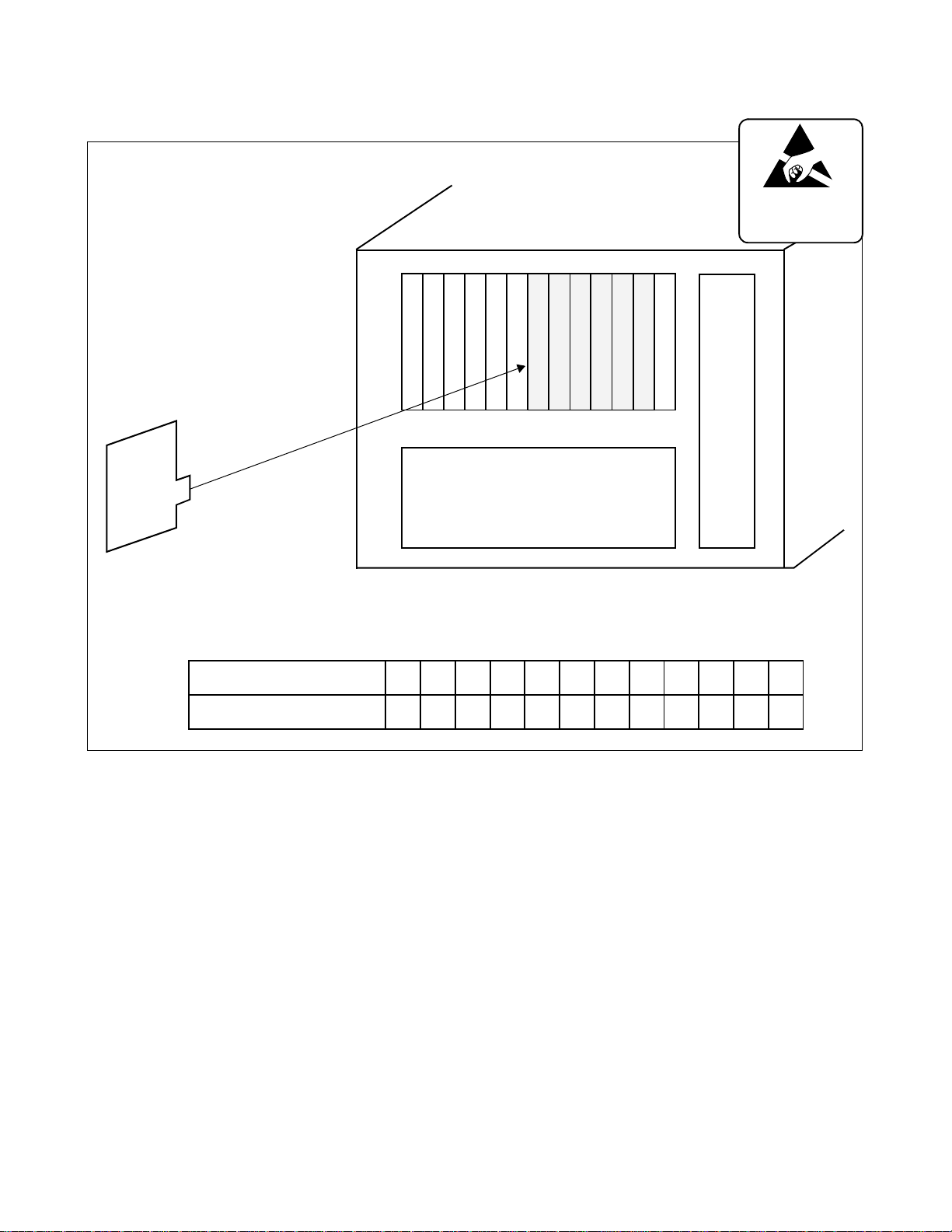
INSTALLATION
• Small Platform System
CSH
CARD
PIM
LT00
LT01
LT02
LT03
LT04
LT05
BUILT-IN BATTERY
ATTENTION
Contents
Static Sensitive
Handling
Precautions Required
LT06/AP0
LT07/AP1
LT08/AP2
LT09/AP3
LT10/AP4
AP5
MP
P
W
R
• Mount the CSH card in the AP slots (AP0-AP5).
• Set the SENSE switch on the CSH card to match an unassigned AP number in CM05 as shown
below.
SLOT NUMBER
SWITCH SETTING VALUE
Figure 3-31 Mounting Location of CSH Card (2 of 3)
04405506607708809910A11B12C13D14E15
F
CHAPTER 3 ND-46248 (E)
Page 72
Revision 2.0
Page 93

• NEAX1000 IVS
CSH
CARD
PIM
LT00
LT01
LT02
BUILT-IN BATTERY
LT03
INSTALLATION
ATTENTION
Contents
Static Sensitive
Handling
Precautions Required
LT04/AP0
LT05/AP1
LT06/AP2
LT07/AP3
LT08/AP4
MP
P
W
R
• Mount the CSH card in the AP slots (AP0-AP4).
• Set the SENS E swit ch on t he CSH card to m atch an unassig ned A P numbe r in CM0 5 as sh own
below.
SLOT NUMBER
SWITCH SETTING VALUE
Figure 3-31 Mounting Location of CSH Card (3 of 3)
04405506607708809910A11B12C13D14E15
F
ND-46248 (E) CHAPTER 3
Page 73
Revision 2.0
Page 94

INSTALLATION
4.10 Connection of ZT
Connect the cable to a ZT via the MDF as shown in Figure 3-32.
Figure 3-33 shows LTC connector corressponds with the LT slots, and CSI pin assignment for each LT slot, and
Figure 3-34 shows an example of the cable connection when the CSI card is mounted in the LT00 slot of PIM0.
PBX
BWB
(PIM0, 2, 4, 6)
CSI
TWISTED-PAIR
CABLE
LTC0/LTC1/LTC2 CONNECTOR
(SEE Figure 3-33
AND Figure 3-34)
Figure 3-32 Cable Connection via MDF for ZT
MDF
Modular
Connector
To ZT
CHAPTER 3 ND-46248 (E)
Page 74
Revision 2.0
Page 95

• NEAX2000 IVS
INSTALLATION
PIM
0, 2, 4, 6
LT00
LT01
LT02
LT04
LT03
LTC0 LTC2
LTC0 LT C1 LTC2
LTC0 LT C1 LTC2
50 MN* 25 MJ* 50 25 50 25
49B5324A53
48 B52 23 A52 48 BB2 23 AB2 48 23
47 B51 22 A51 47 BB1 22 AB1 47 22
46 B50 21 A50 46 BB0 21 AB0 46 21
45B4320A43
44 B42 19 A42 44 BA2 19 AA2 44 19
43 B41 18 A41 43 BA1 18 AA1 43 18
42 B40 17 A40 42 BA0 17 AA0 42 17
41B3316A33
40 B32 15 A32 40 B92 15 A92 40 BF2 15 AF2
39 B31 14 A31 39 B91 14 A91 39 BF1 14 AF1
38 B30 13 A30 38 B90 13 A90 38 BF0 13 AF0
37B2312A23
36 B22 11 A22 36 B82 11 A82 36 BE2 11 AE2
35 B21 10 A21 35 B81 10 A81 35 BE1 10 AE1
34 B20 09 A20 34 B80 09 A80 34 BE0 09 AE0
33B1308A13
32 B12 07 A12 32 B72 07 A72 32 BD2 07 AD2
31 B11 06 A11 31 B71 06 A71 31 BD1 06 AD1
30 B10 05 A10 30 B70 05 A70 30 BD0 05 AD0
29B0304A03
28 B02 03 A02 28 B62 03 A62 28 BC2 03 AC2
27 B01 02 A01 27 B61 02 A61 27 BC1 02 AC1
26 B00 01 A00 26 B60 01 A60 26 BC0 01 AC0
LT05
LT04
LT03
LT02
LT01
LT00
LT07
LT06
LT05
LTC1
49 BB3 24 AB3
45 BA3 20 AA3
41 B 93 16 A93
37 B 83 12 A83
33 B 73 08 A73
29 B 63 04 A63
LT08
LT10/AP0
LT09
LT11
LT10
LT09
LT08
LT07
LT06
LT14/AP4
LT13/AP3
LT12/AP2
LT11/AP1
MP/FP/AP7
LT15/AP5
BUS/AP8
FP/AP6
49 24
45 20
41BF316AF3
37BE312AE3
33BD308AD3
29BC304AC3
P
W
R
LT15
LT14
LT13
LT12
Figure 3-33 Location of LT Slots and LTC Connectors for ZT (1 of 3)
ND-46248 (E) CHAPTER 3
Page 75
Revision 2.0
Page 96

INSTALLATION
• Small Platform Sy stem
50 MN* 25 MJ* 50 25 50 25
49 24
48 23 48 23 48 B92 23 A92
47 22 47 22 47 B91 22 A91
46 21 46 21 46 B90 21 A90
45 B23 20 A23 45 B53 20 A53 45 B83 20 A83
44 B22 19 A22 44 B52 19 A52 44 B82 19 A82
43 B21 18 A21 43 B51 18 A51 43 B81 18 A81
42 B20 17 A20 42 B50 17 A50 42 B80 17 A80
41 16
40 15 40 15 40 15
39 14 39 14 39 14
38 13 38 13 38 13
37 B13 12 A13 37 B43 12 A43 37 B73 12 A73
36 B12 11 A12 36 B42 11 A42 36 B72 11 A72
35 B11 10 A11 35 B41 10 A41 35 B71 10 A71
34 B10 09 A10 34 B40 09 A40 34 B70 09 A70
33 08
32 07 32 07 32 07
31 06 31 06 31 06
30 05 30 05 30 05
29 B03 04 A03 29 B33 04 A33 29 B63 04 A63
28 B02 03 A02 28 B32 03 A32 28 B62 03 A62
27 B01 02 A01 27 B31 02 A31 27 B61 02 A61
26 B00 01 A00 26 B30 01 A30 26 B60 01 A60
LT10/AP4
LT09/AP3
LT08/AP2
LT07/AP1
LT06/AP0
LT00
LT01
LT02
PIM
LTC0 LTC2
LTC0 LTC1 LTC2
LT02
LT01
LT00
LT04
LT03
LTC1
49 24
41 16
33 08
AP5
LT05
LT04
LT03
MP
49 B93 24 A93
41 16
33 08
LT09
LT08
LT07
LT06
Note:
When mounting the Line/Trunk circuit car d with 6 or 8 cir cuits int o the L T08 slot, the L T09 slot
cannot be used.
Figure 3-33 Location of LT Slots and LTC Connectors for ZT (2 of 3)
CHAPTER 3 ND-46248 (E)
Page 76
Revision 2.0
Page 97

• NEAX1000 IVS
LT00
LT01
LT02
LT03
INSTALLATION
LT08/AP4
LT07/AP3
LT06/AP2
LT05/AP1
LT04/AP0
MP
P
W
R
LT03
LT02
LT01
LTC1
49 24
LT08
41 B 73 16 A73
LT06/LT07
LT06
33 B 53 08 A53
LT04/LT05
LT04
LTC0
LTC0 LTC1
50 MN 25 MJ 50 * 25 *
LTC0 LTC1 LTC2
49 24
48 23 48 23
47 22 47 22
46 21 46 21
45 B33 20 A33 45 B83 20 A83
44 B32 19 A32 44 B82 19 A82
43 B31 18 A31 43 B81 18 A81
42 B30 17 A30 42 B80 17 A80
41 16
40 15 40 B72 15 A72
39 14 39 B71 14 A71
38 13 38 B70 13 A70
37 B23 12 A23 37 B63 12 A63
36 B22 11 A22 36 B62 11 A62
35 B21 10 A21 35 B61 10 A61
34 B20 09 A20 34 B60 09 A60
33 08
32 07 32 B52 07 A52
31 06 31 B51 06 A51
30 05 30 B50 05 A50
29 B13 04 A13 29 B43 04 A43
28 B12 03 A12 28 B42 03 A42
27 B11 02 A11 27 B41 02 A41
26 B10 01 A10 26 B40 01 A40
* When AD8 is mounted in LT00, pins 25 and 50 of LTC1 bring out the AD8 internal modem leads.
Figure 3-33 Location of LT Slots and LTC Connectors for ZT (3 of 3)
ND-46248 (E) CHAPTER 3
Revision 2.0
Page 77
Page 98

INSTALLATION
PBX
(PIM0, 2, 4, 6)
BWB
CSI
LTC0/LTC1/LTC2 CONNECTOR
26 RB0 1 RA0
ZT No. 0
ZT No. 1
ZT No. 2
ZT No. 3
27 TB0 2 TA0
28 RB1 3 RA1
29 TB1 4 TA1
30 RB2 5 RA2
31 TB2 6 TA2
32 RB3 7 RA3
33 TB3 8 TA3
34 9
35 10
36 11
37 12
38 13
39 14
40 15
41 16
42 17
43 18
44 19
45 20
46 21
47 22
48 23
49 24
50 25
TWISTED-PAIR
CABLE
TB
RB
RA
TA
MDF
MDF
Note:
Moldular
Connector
To ZT
TB
RB
ZT
TA
RA
Modular Jack
(RJ-45)
Modular plug
Confirm that all feed polarity TA/TB and
RA/RB is normal before connecting ZT to
RJ-45 Modular jack.
TA/TB minus
RA/RB plus
CAUTION:
Incorrect wiring may cause severe damage to the equipment.
Figure 3-34 Example of Cable Connection via MDF for ZT (1 of 2)
CHAPTER 3 ND-46248 (E)
Page 78
Revision 2.0
Page 99

Modular
Connector
INSTALLATION
(8)
(1)
8
7
FUNCTION POLARITY
TERMINAL
NUMBER
COLOR
TERMINAL
NUMBER
TERMINAL
EQUIPMENT
CSI SIGNAL FEED
1 blue a Not used Not used
2 orange b Not used Not used
3 black c Transmission Reception + - RA
4 red d Reception Transmission + - TA
5 green e Reception Transmission - + TB
6 yellow f Transmission Reception - + RB
7 brown g Not used Not used
8 slate h Not used Not used
Note:
RJ-45 Modular Jack is highly recommended.
3
4
5
6
TERMINAL
2
CSI
1
Keep all wiring straight to the jack and perform all reverses at the cross connect for future changes.
Assuming the PN-2CSI-A is in slot LTC0, please make the following connections.
LTC0 RJ-45
White-Blue Yellow
Blue-White Black
White-Orange Green
Orange-White Red
Figure 3-34 Example of Cable Connection via MDF for ZT (2 of 2)
ND-46248 (E) CHAPTER 3
Page 79
Revision 2.0
Page 100

INSTALLATION
4.11 Connection of Battery
CAUTION
If battery terminals (+, –) contact with the module while connecting the bat tery ca ble to the PW86/PW91 card, the
PW86/PW91 card or the BWB may be shorted. There fo re, the installer must perfor m wo rk in accordance with the
following steps when mounting or removing the batteries.
(1) When mounting batteries:
(a) Connect th e battery cable to the batteries.
(b) Mount the batteries into the appointed position of the PIM or the BATTM.
(c) Connect the battery cable to the PW86/PW91 card.
(2) When removing batteries:
(a) Disconnect the battery cable from the PW86/PW91 card.
(b) Remove the batter ies from the PIM or the BATTM .
CHAPTER 3 ND-46248 (E)
Page 80
Revision 2.0
 Loading...