

Page 1

User’s Manual
IP Telephony Gateway
Model No.: SP5008A, SP5018A, SP5058A
Website: http://www.micronet.info
Page 2

About this User’s Manual
This User’s Manual gives users basic steps on installation and operation. Please
read this manual chapter by chapter.
Chapter 1. Introduction
Introduce the IP Telephony Gateway to users in terms of feature, appearance,
and application.
Chapter 2. Startup
Help user complete basic configuration.
Chapter 4. Web Administration
Provide command reference of Web Interface for advanced setting.
Chapter 3. Operation
Show user how to use the device to process phone call.
Chapter 6. Specification
List the specification of the gateway in detail.
Online Upgrade
Please refer to http://www.micronet.info/ for additional support.
1
Page 3

Table of Content
1...Introduction.............................................................................................. 4
1.1 Key Features................................................................................................ 4
1.2 Physical Description..................................................................................... 5
2...Startup...................................................................................................... 7
2.1 Login into the System................................................................................... 7
2.2 Network Configuration.................................................................................. 9
2.2.1 Static IP..........................................................................................................11
2.2.2 DHCP............................................................................................................ 12
2.2.3 PPPoE........................................................................................................... 13
2.2.4 LAN Setting................................................................................................... 14
2.3 General configuration................................................................................. 16
2.3.1 PABX Mode (SP5018A only)......................................................................... 16
2.3.2 SIP Setting .................................................................................................... 18
3...Web Administration............................................................................... 20
3.1 General configuration................................................................................. 20
3.1.1 SIP Advanced Setting.................................................................................... 20
3.1.2 Payload Type Setting.................................................................................... 22
3.1.3 Line Setting ................................................................................................... 24
3.1.4 Qos Setting.................................................................................................... 27
3.1.5 Speed Dial Setting......................................................................................... 28
3.1.6 Caller ID Setting............................................................................................30
3.1.7 CDR Setting .................................................................................................. 32
3.1.8 Syslog Setting ............................................................................................... 34
3.2 Advanced Configuration............................................................................. 36
3.2.1 System setting............................................................................................... 36
3.2.2 SNTP Setting................................................................................................. 40
3.2.3 Codec Setting................................................................................................ 41
3.2.4 Voice Setting................................................................................................. 42
3.2.5 Tone Setting .................................................................................................. 44
3.2.6 Phone Setting................................................................................................ 46
3.2.7 Digit Manipulation.......................................................................................... 48
3.2.8 Dial Plan........................................................................................................50
3.3 Management .............................................................................................. 52
3.3.1 Provision Server............................................................................................ 52
3.3.2 Save-Reload setting...................................................................................... 53
3.3.3 Upgrade Firmware......................................................................................... 54
2
Page 4

3.3.4
Reset to Default............................................................................................. 58
3.3.5 Network Status..............................................................................................59
3.3.6 Version Info................................................................................................... 60
3.3.7 Port Status..................................................................................................... 61
3.3.8 Password....................................................................................................... 62
3.4 Rebooting the system................................................................................. 63
4...Operation................................................................................................ 64
4.1 Peer to Peer mode (FXO to FXS)............................................................... 64
4.2 Peer to Peer mode (FXS to FXS)............................................................... 68
5...Specification........................................................................................... 72
3
Page 5

1. Introduction
Micronet SP5008A / SP5018A / SP5058A are high-capacity SIP Gateway
Series that provides 8 FXS / 4 FXS + 4 FXO / 8 FXO ports, and suit to build an
IP-based communication platform with other VoIP devices. They meet enterprise’s
requirement for functionality (VoIP) upgrade and larger scale implementation by
interoperating with legacy PABX and IP PBX/Soft-switch.
To connect with legacy PABX, SP5018A supports PABX Mode for PSTN
backup. When network or power fails, PSTN lines (FXO) bypass to FXS ports and
users still can make/receive calls via PSTN lines.
In addition, SP5008A includes some wonderful PABX features for small
business. They help operate users on various VoIP applications, such as extension
calling among 8 FXS ports, inbound/outbound calls via SIP trunk, DID (direct line),
DOD, prefix routing, operator attendant, etc. Users can easily benefit from the
ease-to-use device.
1.1 Key Features
z IETF SIP standards compliant
z Support 1 RJ-45 WAN port and 4 RJ-45 LAN ports
z Support POTS interfaces: 8 FXS / 4 FXS + 4 FXO / 8 FXO ports
z Support single-account registration on FXS ports for representative number
z Support extension calling among FXS ports
z Support rich call features: call hold, call transfer, call forward, hotline, warm line,
speed dial, anonymous call, P2P call, etc
z Support PSTN prefix routing (SP5018A only)
z Support PABX mode for legacy PABX function upgrade (SP5018A only)
z Support PSTN lifeline – PSTN bypass in case of power or registration failure
(SP5018A only)
z Support detection of disconnect tone, polarity reversal, and loop current drop
(zero voltage) on FXO ports
z Well interoperability with industry-leading IP-PBX/Soft-Switch, such as Alcatel,
Lucent, Siemens, etc.
4
Page 6
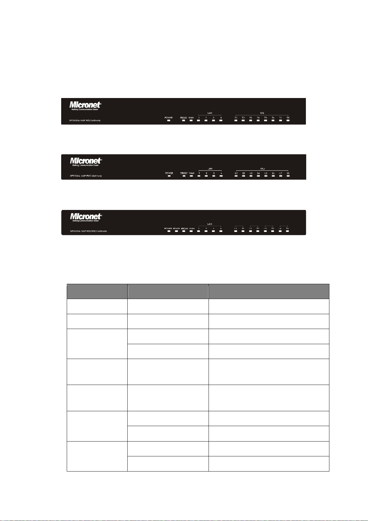
1.2 Physical Description
SP5008A:
SP5008A Front Panel
SP5058A
SP5058A Front Panel
SP5018A
SP5018A Front Panel
LED Indicators
LED Status Description
POWER On / Green The Power is on
READY Blink / Green Booting up for self test
Blink / Green Gateway reg. fails PROXY
Constant / Green Gateway reg. successes
WAN Blink / Green Transmitting or receiving data /Network
connection established
LAN(1-4) Blink / Green Transmitting or receiving data /Network
connection established
On / Orange Busy / Off-hook T(1*)
Off Available / On-hook
On / Orange Busy L(1*)
Off Available
5
Page 7

1*.
SP5008A: FXS = T1 - T8
SP5018A: FXS = T1 - T4, FXO = L1 - L4
SP5058A: FXO = L1 - L8
SP5008A
SP5058A
SP5018A
SP5008A Rear Panel
SP5058A Rear Panel
SP5018A Rear Panel
---------------------------------------------------------------------------------------------------
RESET Factory default button. Press and hold for 5 seconds to reset
T1-T8 The RJ-11 FXS port 1-8, connects analog phone sets, trunk line in PABX.
L1-L8
The RJ-11 FXO port 1-8, connect to PSTN
T1/P1-T4/P4 It is a pair of FXO and FXS connector. The different is that the when power off
or application is crashed, the FXO and FXS will be connected together
automatically for local surviving.
WAN RJ-45 port of 10/100M for connecting to modem
LAN(1-4) RJ-45 port of 10/100M for connecting to PC or hub/switch that connects PCs
DC 12V The power socket, input AC 100V~120V; output DC12V.3A
---------------------------------------------------------------------------------------------------
6
Page 8
2. Startup
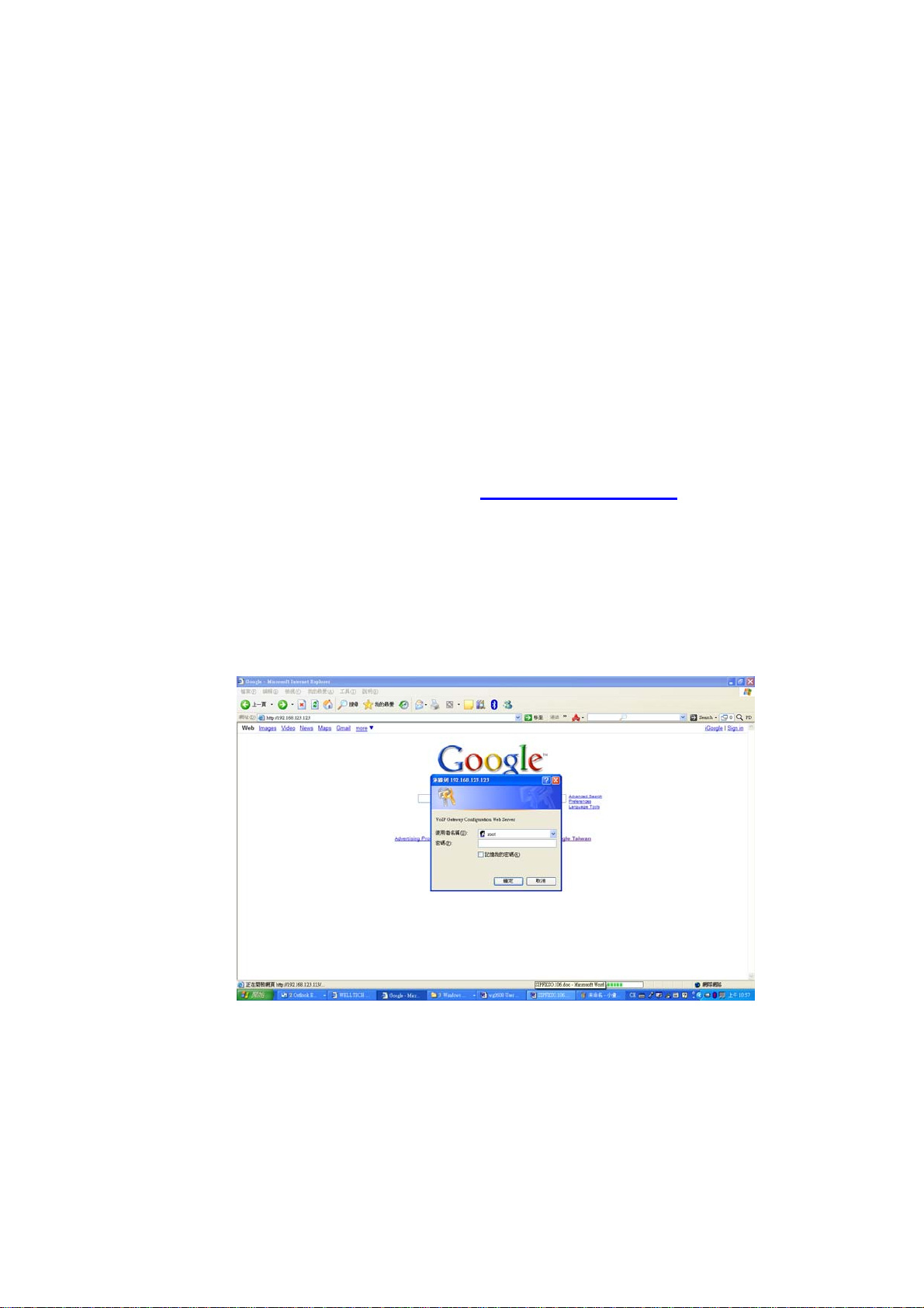
2.1 Login into the System
First of all, connect your computer to MICRONET SP5008A / SP5018A / SP5058A’s
LAN port by using DHCP. The IP address assign to your computer should be
192.168.123.x by default. Once you can get the IP address from MICRONET
SP5008A / SP5018A / SP5058A, you can start the configuration as below.
Step 1. Connect LAN port to your managing PC. Or, connect the gateway with PC
by hub/switch.
Step 2. Launch your web browser with http://192.168.123.123/. Please configure
IP address of PC with 192.168.123.x. Or set up your PC in DHCP mode to
get IP address automatically.
Step 3. The Password screen now appears. Type “root” in the user name field,
and your password (none by default) in the password field.
Step 4. You will enter the main page of the web configuration interface after you
keyed in the username and password correctly (see figure below).
7
Page 9

8
Page 10
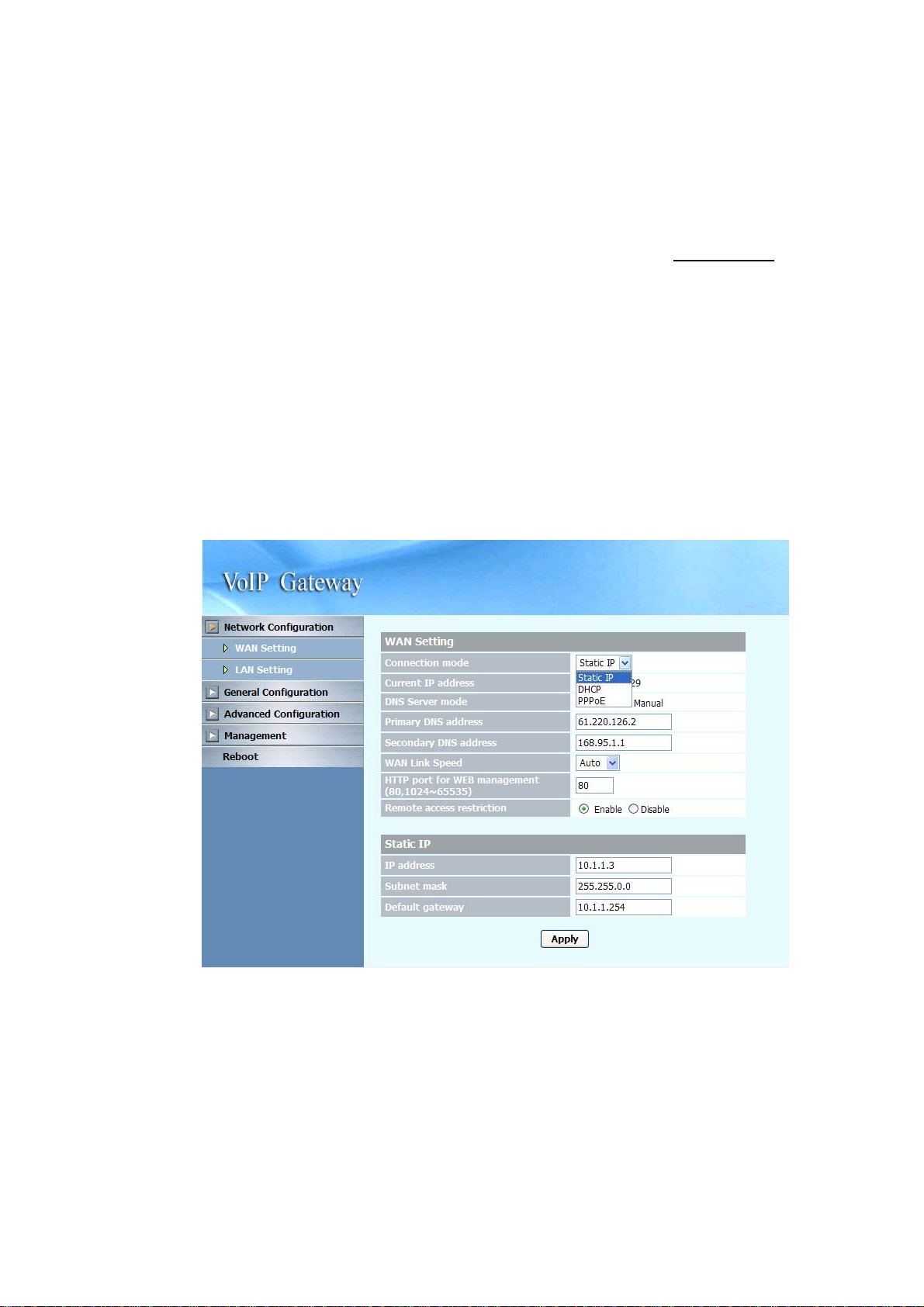
2.2 Network Configuration
By default, the gateway is in NAT mode (router mode) and can share Internet
access with PCs. Go to [ Network Configuration / WAN Setting ], and configure
WAN setting according to actual condition. In default IP type of DHCP client, it
requests necessary IP information from your ISP automatically.
-----------------------------------------------------------------------------------------------------
Note:
1. Different ISPs require different methods of connecting to the Internet. Please consult your
ISP to select right IP type (Fixed IP, PPPoE) of WAN.
2. You can retrieve the IP address of the WAN port by keying #126# on the phone set that is
connected to the FXS port of the gateway. You will hear an IVR announcing the current IP
address of the WAN port.
-----------------------------------------------------------------------------------------------------
9
Page 11

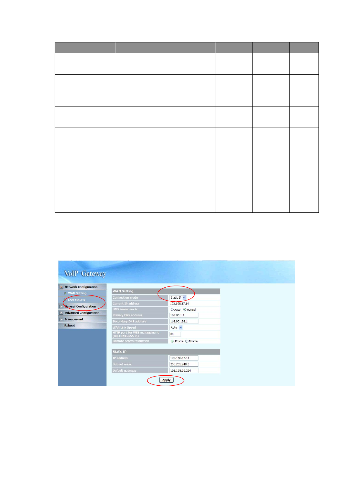
WAN Setting
Item Description Static IP DHCP PPPoE
Connected mode Select the connection method for
the WAN port of the
SP5008A/SP5018A/SP5058A, you
can choose the following:
z Static IP
z DHCP
z PPPoE
Current IP Address Show current IP address
DNS server mode Select the DNS behavior, you can
choose the following:
z Auto
z Manual
“DNS auto” will retrieve the DNS
information sent from the DHCP
server.
“Manual” will look at the specified
Primary and Secondary DNS
address.
Primary DNS
address
Specify the address of the Primary
DNS.
V V V
V V V
V V V
V V V
Secondary DNS
address
WAN Link Speed Select the connection speed for the
HTTP port for WEB
management
IP address Specify the IP address.
Subnet mask Specify the subnet mask.
Specify the address of the
Secondary DNS.
WAN port of the
SP5008A/SP5018A/SP5058A, you
can choose the following:
z Auto
z 100M
z 10M
Specify the port number for WEB
management, the allowable range is
80,1024~65535.
V V V
V V V
V V V
V
V
10
Page 12
Item Description Static IP DHCP PPPoE
Default gateway Specify the IP address of the default
gateway.
Remote access
restriction
PPPoE userID Specify the username of the PPPoE
PPPoE password Specify the password associated to
Reboot after remote
host disconnection
Restricts/Blocks user s con nectin g to
the WAN port’s IP remotely, you can
Enable/Disable this option.
account
the PPPoE account above.
When the remote host (PPPoE)
fails, the gateway will retry 3 times
to reconnect, if there is no reply
from the remote host within 3 tries,
then the gateway will reboot. You
can Enable/Disable this option.
V
V V V
V
V
V
2.2.1 Static IP
1. Press the “Apply” button (at the bottom) after you finish to save changes.
11
Page 13
2. Press the “Reboot” button to apply the changes.
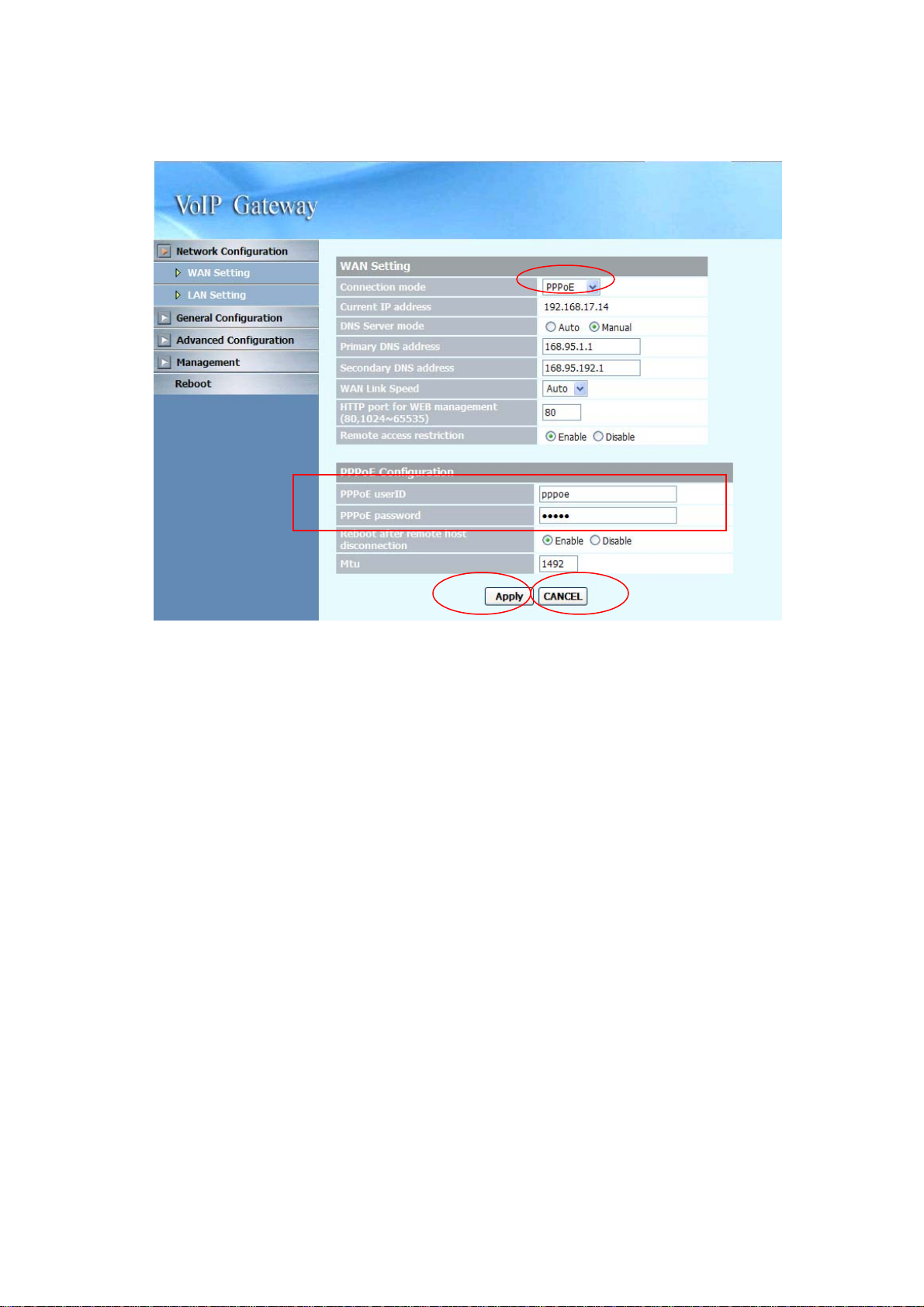
2.2.2 DHCP
1. Press the “Apply” button (at the bottom) after you finish to save changes.
2. Press the “Reboot” button to apply the changes.
-----------------------------------------------------------------------------------------------------
Note:
When you are using DHCP in WAN and not connected, please make sure you connect Ethernet
before use PC to connect to LAN port.
-----------------------------------------------------------------------------------------------------
12
Page 14
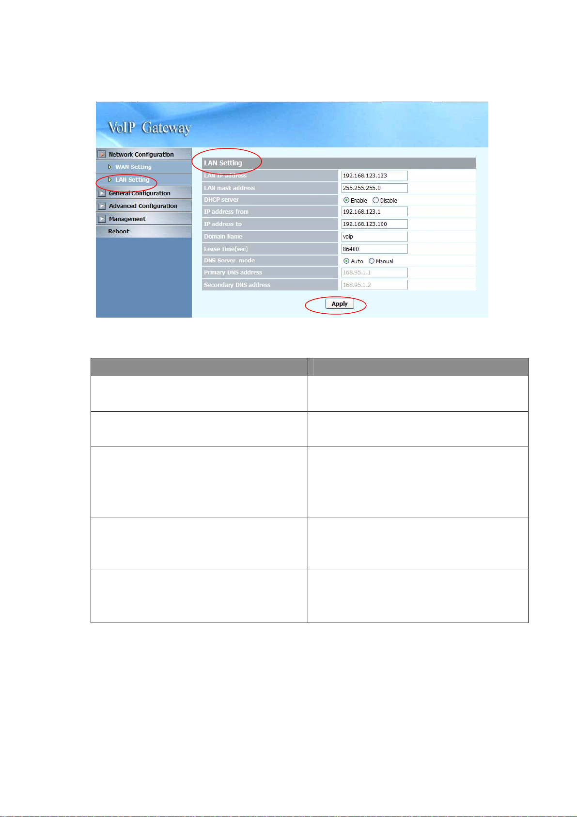
2.2.3 PPPoE
1. Input PPPoE user ID and password
2. Press the “Apply” button (at the bottom) after you finish to save changes.
3. Press the “CANCEL” button (next to the Apply button) to clear the values in
the page.
4. Press the “Reboot” button to apply the changes.
13
Page 15
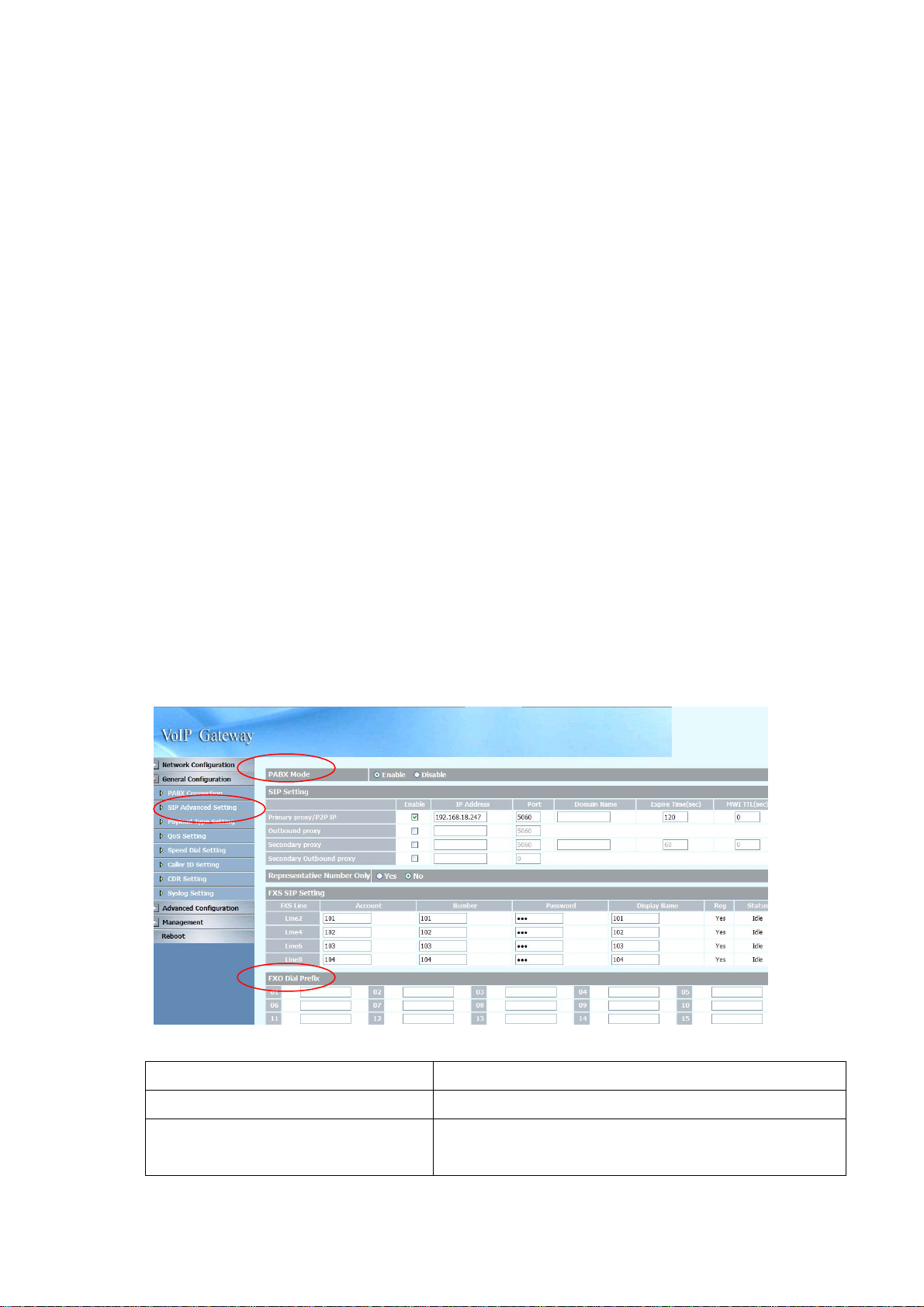
2.2.4 LAN Setting
ITEM Description
LAN IP address Specify the IP address of the SP5008A /
SP5018A / SP5058A LAN port.
LAN mask address Specify the mask address for SP5008A /
SP5018A / SP5058A LAN port.
DHCP server
IP address from When DHCP is enabled, you can specify the IP
IP address to When DHCP is enabled, you can specify the
Enable/Disable DHCP function on the LAN port.
Once enabled, the LAN ports will function as a
DHCP server, network devices connected to
them will be issued with IP addresses.
address to start from when assigning to attach
network devices.
ending IP address assigned to the attached
network devices.
14
Page 16

ITEM Description
Domain Name You can specify the domain name that will be
assigned by the DHCP server to the attached
network devices. The DHCP server will send
information on the “server host name” to the
DHCP client.
Lease time(sec) You can specify the maximum lease time of the
IP address allocated to the DHCP client.
DNS server mode Select the DNS behavior, you can choose the
following:
z Auto
z Manual
“DNS auto” will retrieve the DNS information sent
from the DHCP server.
“Manual” will look at the specified Primary and
Secondary DNS address.
Primary DNS address Specify the address of the Primary DNS.
Secondary DNS address Specify the address of the Seconda ry DNS.
1. Press the “Apply” button (at the bottom) after you finish to save changes.
2. Press the “Reboot” button to apply the changes.
15
Page 17
2.3 General configuration
To make VoIP calls, you will need a SIP account provided by the SIP Proxy you are
registered with. To configure the relevant SIP settings, please refer to the
instructions explained below.
2.3.1 PABX Mode (SP5018A only)
This quick setting is used for MICRONET SP5018A to operate in PABX connection
mode between PSTN and traditional PABX. Enable PABX mode for ISP/ITSP
scenario that forbids SIP call to/from PSTN via the gateway (SP5018A). The call
scenario will be working as below:
1. For FXO incoming call, it will route to corresponding FXS directly (1 by 1)
2. For FXS outgoing call, it will route to VOIP except those prefix set in FXO
dialing Prefix.
3. For VOIP incoming call, it will route to FXS based on the called number
4. When VOIP call is failed to be called out such as register fail or network
issue, the call will be route to FXO as backup.
5. When MICRONET SP5008A / SP5018A / SP5058A is malfunction or
power failure, the all call will be directly bypassed to FXO.
P ABX Conn e ction
SIP Setting
Representative Number Only
To enable PABX behavior or not.
Please refer to 3.3.2.1
It is used (Yes) when you only have 1 SIP account and
would like to be shared for all FXS lines. Please refer to
16
Page 18

3.3.2.1
Primary FXS SIP settings
FXO Dialing Prefix
When you have multiple SIP accounts for each FXS line,
please set Representative Number Only to No. Then refer
to 3.3.2.1 for the detail
When the prefix is set here, the call will be route to FXO
instead of VOIP.
17
Page 19
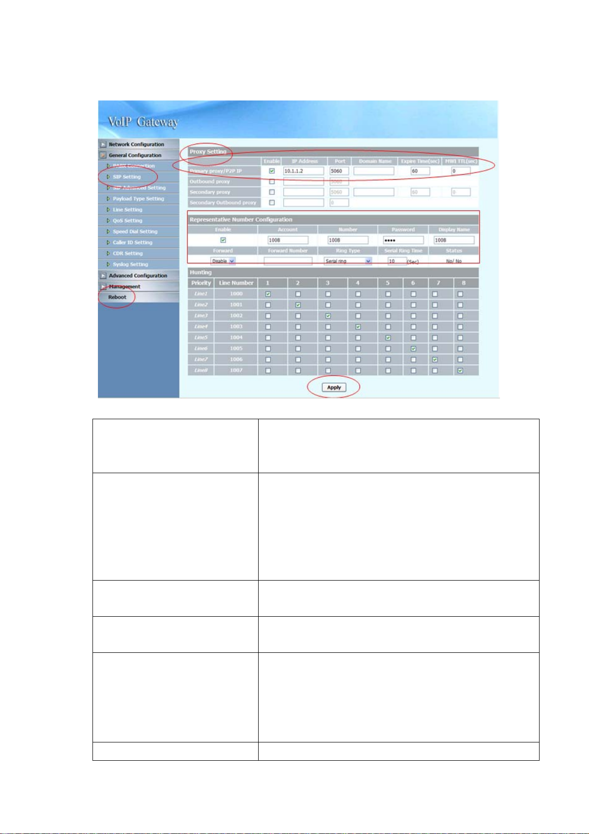
2.3.2 SIP Setting
Primary proxy/P2P IP
Secondary proxy
Outbound proxy
Secondary Outbound proxy
Representative Number
Specify the data of prima ry proxy : Enable/Disable, IP
address, Port#, Domain Name, Expire time and MWI TTL.
The P2P mode will be explained in paragraph Appendix A
Specify the data of secondary proxy: Enable/Disable, IP
address, Port#, Domain Name, Expire time and MWI TTL.
When you enable secondary proxy, it will start to register no
matter whether primary proxy is registered or not. However, it
will be used only when primary proxy is not registered or the
incoming call is coming from it.
Specify the data of Outbound proxy: Enable/Disable, IP
address and Port#.
Specify the data of Outbound proxy for secondary proxy:
Enable/Disable, IP address and Port#.
The representative number is working as a SIP trunk for the
selected FXS line (for all FXS or FXO/FXS combination
Enable
model) or FXO line (for all FXO model). When an incoming
call to the representative number, the selected FXS or FXO
port will be hunted.
Enable the Line, the default setting is “Enable” and it will
18
Page 20

Register or Unregister to SIP Proxy
Account
Number
Password
Display name
Forward
Forward Number
Ring Type
Ring Time (s) for Serial ring
Status
Input the SIP Proxy registration account ID.
Input the phone number.
Input the password of IP Proxy registration account ID.
Specify the Display name of the phone number
Specify the Represent ative forwarding type to be used, only
choose busy
Specify the number to be forwarded wh en the specified
forward condition is met.
Select the Ring Type of representative number. You can
choose the following:
z Serial ring (Follow the ring priority defined
below)
z Simultaneous(ring all)
Specify the Ring Time for Serial ring
Displays the registration status, whether it is registered or not.
Priority
Select the group of representative number, and specify the
priority.
Only the checked line will become the member of the
representative number.
The default setting L1~L8 is grouped.
1. Enter the IP address and port number of the SIP proxy into the Primary proxy
address and Port fields. Press the “Apply” button to save changes.
2. Press the “Reboot” button to apply the changes.
19
Page 21
3. Web Administration
3.1 General configuration
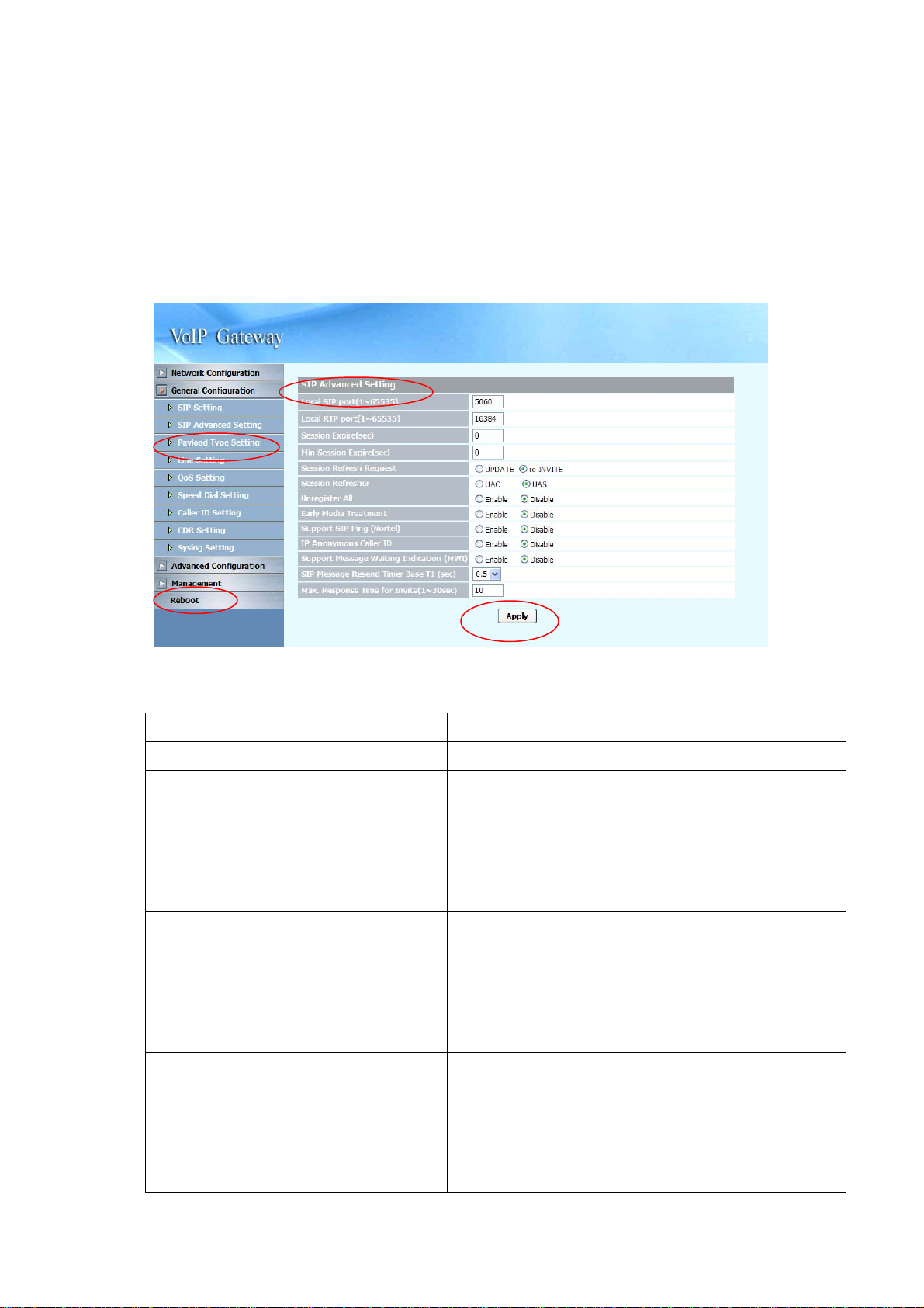
3.1.1 SIP Advanced Setting
Local SIP port (1~65535)
Local RTP port (1~65535)
Session Expire (Sec)
Min Session Expire (Sec)
Session Refresh Request
Session Refresher
Specify the local SIP port’s number.
Specify the local RTP port’s number.
Specify the session expire time that will be used to
negotiate with the remote host or proxy.
Specify the minimum session expire time that other host
or proxy will need to follow when calling the MICRONET
SP5008A/SP5018A/SP5058A.
Select the session refresh method that will be used on
the MICRONET SP5008A/SP5018A/SP5058A, you can
choose among the two methods:
z UPDATE
z Re-Invite
Select who will perform the refreshes, you can choose
among the two methods:
z UAC (Client)
z UAS (Server)
This will add the parameter refresher=uac or uas in the
20
Page 22

Session Refresh Request message.
Unregister All
Early media Treatment
Support SIP Ping
IP Anonym ous Caller ID
Support Message Waiting Indication
(MWI)
SIP Message Resend Timer Base (sec)
Send SIP unregister signaling message after the
SP5008A / SP5018A / SP5058A has been restarted
Use early media treatment SIP protocol, where SIP
invite messages will not include SDP.
Special feature used with o nly Nortel’s SIP proxy.
When this feature is Enabled, all IP outgoing calls’
Caller ID will not be displayed to the destination.(Please
make sure your proxy server or soft switch
supports the feature, if the proxy does not suppor t
it and you enable this feature, all IP outgoing calls
will be dropped.)
When Disabled, all IP outgoing calls’ Caller ID will be
displayed to the destination.
You can Enable or Disable the MWI function.( This
feature is for FXS only)
Specify the resend time in seconds for ea ch SIP req uest
message that has not received a response.
Max. Response Time for Invite
(1~30sec)
Specify the timeout period for SIP Invite messages.
For example, if the timeout period is 10 seconds, when
the SP5008A / SP5018A / SP5058A sends an Invite
message and does not receive a response within 10
seconds, it will cancel the call.
1. Press the “Apply” button (at the bottom) after you finish to save changes.
2. Press the “Reboot” button to apply the changes.
21
Page 23
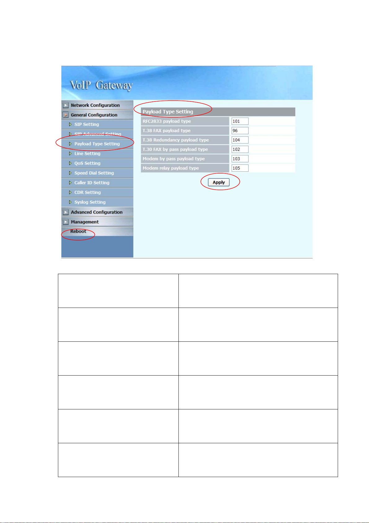
3.1.2 Payload Type Setting
RFC2833 payload type
T.38 FAX payload type
T.38 Redundancy payload type
T.30 FAX by pass p ayload type
Modem by pass payload type
Specify the RFC2833 payload type (range is 96~128,
however 100, 102~105 is reserved by other payload
types).
Specify the FAX payload type (range is 96~128,
however 100, 102~105 is reserved by other payload
types)
Specify the Redundancy p ayload type (range is 96~128,
default value is 104. 100, 102, 103, 105 is reserved by
other payload types).
Specify the FAX by pass payload type (range is 96~128,
default value is 102. 100, 103~105 is reserved by
other payload types).
Specify the Modem by pass payload type (range is
96~128, default value is 103. 100, 102, 104, 105 is
Modem relay payload type
reserved by other payload types).
Specify the Modem relay p ayload type (range is
96~128, default value is 105. 100, 102~104 is
reserved by other payload types).
22
Page 24

1. Press the “Apply” button (at the bottom) after you finish to save changes.
2. Press the “Reboot” button to apply the changes.
23
Page 25

3.1.3 Line Setting
24
Page 26

No Answer Forward Time (FXS only)
If you enable the No Answer Forward
function (Representative number or
L1~L8 number), please specify the
time of no answer. The default setting
is 30 sec.
FAX
Line1~Line8 relevant data
Type
Enable
Reg
Number
Enable Hotline
Hotline Number
Enable/Disable FAX T.38 function.
Displays the port type of that particular line.
Enable the line or not
Register or Unregister to SIP Proxy
Displays the line numbers that specified in SIP Setting.
Account: Input the SIP Proxy registration account ID.
Number: Input the phone number.
Password: Input the password of IP Proxy regist ration account
ID.
Display name: Specify the Display name of the phone
number.
The first is the number registers to Primary proxy.
The default setting is 1000~1007.
Click the check box to enable hotline feature. If enabled, The
check box will display as
.
Specify the number to forward the call to when the Hotline
Wait to Hotline(sec)
Forward Type
Forward Number
Call Waiting (FXS only)
DND (FXS only)
Greeting (FXO only)
feature is enabled.
Specify the time (sec) for wait to hotline, the default value is 0.
Specify the forwarding type to use, you can choose the
following:
z Disable
z Unconditional
z Busy
z No Answer (FXS only)
z Busy and No Answer (FXS only )
The “Disable” option will allow you to disable this particular
function.
Specify the number to forward the call to when the call
forwarding feature is enabled.
Enable/Disable per-line Call Waiting fun ction.
Enable/Disable per-line DND (Do Not Disturb) function.
Enable/Disable Greeting for FXO
25
Page 27

1. Press the “Apply” button (at the bottom) after you finish to save changes.
2. Press the “Reboot” button to apply the changes.
26
Page 28

3.1.4 Qos Setting
Type
Differentiated Services Code Point Setting (DSCP)
DSCP RTP
DSCP Signal
ToS Setting
ToS RTP
ToS Signal
Select Qos Type: DSCP or ToS
Select the DSCP value for RTP (voice packets), the
value in the drop down list is expressed in binary
format, you can choose to meet your network
environment.
Select the DSCP value for SIP message, the value in
the drop down list is expressed in binary format, you
can choose to meet your network environment.
Select the ToS value for RTP (voice packets), the
value in the drop down list is expressed in binary
format, you can choose to meet your network
environment.
Select the ToS value for SIP messages, the value in
the drop down list is expressed in binary format, you
can choose to meet your network environment.
1. Press the “Apply” button (at the bottom) after you finish to save changes.
2. Press the “Reboot” button to apply the changes.
27
Page 29

3.1.5 Speed Dial Setting
Speed Dial
Speed Dial Editor
Specify the speed Dial Number/Telephone Number/Name,
then press the Add or Del button to add or delete record
28
Page 30

Peer to Peer call
You can use speed dial to do the peer to peer call as follows:
Speed Dial Editor
(In P2P application)
Specify the speed Dial Number/Telephone
Number/Name, then press the Add or Del button
to add or delete record
The format of “Telephone Number” is “#@ip
address: port”, for example
2000@192.168.23.58:5060
29
Page 31

3.1.6 Caller ID Setting
Caller ID Setting (Line 1~Line 8)
Select the (Line 1~Line 8)Caller ID generation
type to use, you can choose the following:
z Disable
z DTMF
z FSK(Bellcore)
z ETSI(Before Ring)
z ETSI(Between ring)
FXO only choose Enable/Disable the caller ID
detection
AUTO: You can choose different caller ID type by
line. If Line1~Line 8 uses the same type, you
only need to set line 1 and click the “Auto” button,
then the other lines will set the same type
automatically.
The “Disable” option will allow you to disable this
DTMF Caller ID Start Symbol
DTMF Caller ID End Symbol
particular function.
Specify the DTMF Caller ID Start Symbol
The default symbol is D.
Specify the DTMF Caller ID End Symbol
30
Page 32

The default symbol is C.
1. Press the “Apply” button (at the bottom) after you finish to save changes.
2. Press the “Reboot” button to apply the changes.
31
Page 33

3.1.7 CDR Setting
CDR mode
CDR Server address
CDR Server port
Select the CDR mode for Enable or Disable. If
you Enable this feature, please specify the CDR
Server address and port number at the CDR
server address and port’s text box, then you can
get Call Detail Data form CDR Server.
If you Enable the CDR mode, please specify the
IP address of CDR Sever for data storage.
Specify the CDR Server port number,
The default port number is 514.
1. Press the “Apply” button (at the bottom) after you finish to save changes.
2. Press the “Reboot” button to apply the changes.
NOTE: To receive the SYSLOG CDR, you need to have a syslog server to collect
the CDR from MICRONET SP5008A / SP5018A / SP5058A. The following is a tool
you can be used for testing purpose which can be downloaded from
http://tftpd32.jounin.net/. You need to enable syslog server from settings before you
can use it.
32
Page 34

33
Page 35

3.1.8 Syslog Setting
This syslog is used to send the debug log from MICRONET SP5008A / SP5018A /
SP5058A to syslog server.
Syslog mode
Syslog Server address
Syslog Server port
Select the Syslog mode for Enable or Disable. If
you Enable this feature, please specify the
Syslog Server address and port number at the
Syslog server address and port’s text box, then
you can get detail system log from Syslog server.
If you Enable the Syslog mode, please specify
the IP address of Syslog Sever for data storage.
Specify the Syslog Server port number,
The default port number is 514.
1. Press the “Apply” button (at the bottom) after you finish to save changes.
2. Press the “Reboot” button to apply the changes.
NOTE:
server to collect the debug information from MICRONET SP5008A / SP5018A /
To receive the SYSLOG debug information, you need to have a syslogd
SP5058A . The following is a tool you can be used for testing purpose which can be
downloaded from http://tftpd32.jounin.net/. You need to enable syslog server from
settings before you can use it.
34
Page 36

35
Page 37

3.2 Advanced Configuration
3.2.1 System setting
prack
ROH (FXS only)
Send billing signal (FXS only)
T.38 NoAttribute
FAX redundancy depth
PRACK is defined in RFC 3262: Reliability of
Provisional Responses in SIP. You can
accommodate your softswitch (Proxy Server) to
Enable or Disable this feature.
Receiver-Off-Hook (ROH) Tone
A ROH tone is sent to the subscriber to inform
him that his receiver is off-hook.
You can Enable/Disable this option.
Polarity Reversal for billing signal, you can
enable (Reverse)/Disable the feature.
No attribute (Fax version, BitRate, Buffer,
Datagram…) indicated in T.38 Re-Invite with
Session Description Protocol (SDP).
You can Enable/Disable this option.
Specify the resend times (0~3)for FAX error
packet,
T.38 FAX T ype
Select the FAX Type to use, you can ch oose the
following:
z T.38
z ByPass
36
Page 38

z Auto
T.30 FAXByPass Codec
Flash key function (FXS only)
Keypad DTMF type
End of dial key
Select the FAX ByPass Co dec to use, you can
choose the following:
z G.711 a-law
z G.711 u-law
z G.726 32k
Select the function of Flash key, you can choose
the following:
z Disable
z Transfer
z SIP Message
Select the type of Keypad DTMF, you can
choose the following:
z In-Band
z RFC2833
z SIP Info
Select the End of dial key, you can choose the
following:
DTMF Detection Sensitivity
Dial Wait Timeout (1~60sec)
Inter Digits Timeout (1~5sec)
FAXByPass Keyword
FAXByPass Keyword
z Disable
z *
z #
Specify the grade of DTMF Detection Sensitivity,
the value range is (1~5)
Specify the duration of dial waiting when the
receiver is off hook. The range is 1~60 sec.
Specify the interval of input digits, if the interval i s
over the setting, the system will end the dial and
send out the DTMF. The limitation range is
1~5sec.
Some SIP Proxy need specify special keyword
for FAXByPass function. Input the dat a as SIP
Proxy required.
Some SIP Proxy need specify special keyword
for FAXByPass function. Input the dat a as SIP
IP Address announcement
Proxy required.
You can Enable/Disable this function,
If you select Enable, you can connect T1 port
with a phone set and press #120#, you will hear
37
Page 39

the announcement of IP address of LAN port, or
press #126# to get WAN port IP address.
FXO please following under step:
1. You can get a PSTN line and connect to the
L1 FXO port.
2. Use another PSTN phone to dial the PSTN
number (in step 1you connected on
FXO-08), you will hear a second dial tone
or greeting (please dial extension number).
3. Press #126# on the phone set, and you will
hear an IVR announcing the current IP
address of the WAN port.
4. Press #120# on the phone set, and you will
hear an IVR announcing the current IP
address of the LAN port.
Built-in Call Hold Music
DTMF Duration
DTMF Interdigit Time
Ring Time Limit ( 10~600sec )
(FXS only)
Loop Current Drop Duration (0:disable,
100~1000ms )
FXS Voltage Drop (FXS only)
System built-in music of call hold, you can
Enable/Disable this feature.
Specify the DTMF tone duration.
Specify the interval of DTMF digit
Specify the limitation of Ring time for incoming
call, when the ring is over the limit, system will
drop the call. The default range is 10~600sec.
Specify the duration (100~1000m s) of loop
current drop, 0 for disable. This feature is used
when the SP5008A (FXS) are connected with
answering machines. When the remote site
disconnects, the system will drop FXS port’s
voltage to 0, and make the answering machines
disconnect.
This option is used when a stand alone relay box
containing a PSTN and FXS port is connected to
the SP5008A’s FXS port. In this special
application, if there is a network or registration
failure, the system will drop the FXS port’s
voltage to 0, when the relay box detects the
status, it will switch the line to PSTN.
38
Page 40

The default setting is “Disable”, if you are not
using this particular special application
mentioned above, please do not enable this
function.
ping ip to keep alive network
ping timer(sec)
Specify the IP for pinging to make sure the
network keeps alive.
Specify the interval of ping timer(sec)
1. Press the “Apply” button (at the bottom) after you finish to save changes.
2. Press the “Reboot” button to apply the changes.
39
Page 41

3.2.2 SNTP Setting
SNTP mode
SNTP server address
Time Zone -GMT
Time setting
Select the SNTP mode : On or Off
Specify the SNTP server address for time synchronization.
Select the Time Zone of your location
You can specify the time with year/month/date /hour/minute
/second when you select the SNTP mode with “Off”.
1. Press the “Apply” button (at the bottom) after you finish to save changes.
2. Press the “Reboot” button to apply the changes.
40
Page 42

3.2.3 Codec Setting
Codec Priority
Codec Packet Size
Bandwidth Required
Y ou can specif y the priority of the codec from First to Fifth (first
being the highest priority and Fifth being the lowest). You
can choose the following codec’s:
z G711U
z G711A
z G723
z G729A
z G726
You can specify the packet size in the drop down list for each
particular codec, you can choose the following:
G711U 10,20,30,40,50,60
G711A 10,20,30,40,50,60
G723 30,60,90
G729A 10,20,30,40,50,60
G726 10,20,30,40,50,60
When you select the codec packet size shown above, system
will set default requirement of bandwidth.
1. Press the “Apply” button (at the bottom) after you finish to save changes.
2. Press the “Reboot” button to apply the changes.
41
Page 43

3.2.4 Voice Setting
Jitter Buffer
Minimal Delay
Maximal Delay
OPTFactor
VAD
Echo cancellation
Local voice volume
Remote receive volume
Specify the minimal delay of the jitter buffer. The range is
0~150 ms and the default setting is 0 ms.
Specify the maximal delay of the jitter buffer. The range is
0~200 ms and the default setting is 200 ms.
Specify the dynamic jitter buf fer frame error/del ay optimization
factor, the range is 0~13.
Enable/Disable the VAD (Voice Activity Detection) feature.
This is supported on all codecs that the FXS-FXO equips.
Enable/Disable the echo cancellation feature. The default
setting is “Enable”.
Specify the volume gain of the voice in the local side (0~63,
default is 32). You can set this option for ea ch of the 8 lines.
Specify the volume gain of the voice in the remote sid e (0~63,
default is 32). You can set this option for ea ch of the 8 lines.
DTMF volume
Specify the volume gain of the DTMF (0~63, default is 27).
42
Page 44

You can set this option for each of the 8 lines.
1. Press the “Apply” button (at the bottom) after you finish to save
changes.
2. Press the “Reboot” button to apply the changes.
43
Page 45

3.2.5 Tone Setting
Dial tone
Ringback tone (FXS only)
Busy tone
Call-waiting (FXS only)
Voice-Notify (for FXS+PSTN only)
ROH Tone (FXS only)
Specify the p attern of the Dial tone, you can adjust the
high frequency, low frequency, high level, low level, the
On and Off time for tone 1 and 2.
Specify the p attern of the Ring ba ck ton e, you ca n adjust
the high frequency, low frequency, high level, low level,
the On and Off time for tone 1 and 2.
Specify the pattern of the Busy tone, you can adjust the
high frequency, low frequency, high level, low level, the
On and Off time for tone 1 and 2.
Specify the p attern of the call-waiting ton e, you can
adjust the high frequency, low frequency, high level, low
level, the On and Off time for tone 1 and 2.
Specify the pattern of the Voice-Notify, you can adjust
the high frequency, low frequency, high level, low level,
the On and Off time for tone 1 and 2.
Specify the p attern of the ROH Tone, you can adjust the
Disconnect tone 1
high frequency, low frequency, high level, low level, the
On and Off time for tone 1 and 2. The ROH tone is a
single high frequency tone used to warn users that their
phone is not placed on-hook (hang up) correctly.
Specify the pattern of the disconnect ton e for disconnect
tone 1 (first set), you can adjust the high frequency, low
frequency, high level, low level, the On and Off time for
tone 1 and 2.
44
Page 46

NOTE: If the disconnect tone only has single frequency,
please set it to low frequency. If the disconnect tone
only has single cadence, please set it to Tone 1.
Disconnect tone 2
Specify the pattern of the disconnect ton e for disconnect
tone 2 (second set), you can adjust the high frequency,
low frequency, high level, low level, the On and Off time
for tone 1 and 2.
NOTE: If the disconnect tone only has single frequency,
please set it to low frequency. If the disconnect tone
only has single cadence, please set it to Tone 1.
1. Press the “Apply” button (at the bottom) after you finish to save changes.
2. Press the “Reboot” button to apply the changes.
45
Page 47

3.2.6 Phone Setting
Primary Ringing
Ringing Frequency
Ringing ON
Ringing OFF
Ringing level
Flash low
Flash high
Specify the Ringing freque ncy value.
ringing frequency : 15~100 (Unit : Hz)
Specify the Ringing ON value.
ringing ring ON : 0~8000 (Unit : ms)
Specify the Ringing OFF value.
ringing ring OFF : 0~8000 (Unit : ms)
Specify the ringing level.
ringing level : 0 ~ 94 (Unit : V)
Specify the value of the flash (low).
: 60~2000 (Unit : ms).
If the phone-set’s flash time is smaller than the Flash Low
setting, the flash will be ignored.
Specify the value of the flash (high).
: 60~2000 (Unit : ms)
If the phone-set’s flash time is larger than the Flash high
setting, the flash will be handled as hang-up.
Secondary Ringing (FXS only)
Note: The feature will be enabled automatically when the Min. Digit Count has been enabled and
specified. It is used to have different ring cadence when the incoming caller number is shorter than
the setting of “Min. Digit Count”
46
Page 48

Ringing Frequency
Specify the Ringing freque ncy value.
ringing frequency : 15~100 (Unit : Hz)
Ringing ON
Ringing OFF
Ringing level
Min. Digit Count
Country
Specify the Ringing ON value.
ringing ring ON : 0~8000 (Unit : ms)
Specify the Ringing OFF value.
ringing ring OFF : 0~8000 (Unit : ms)
Specify the ringing level.
ringing level : 0 ~ 94 (Unit : V)
Specify the minimum digit count (1~10, 0: Disabl e), this
feature is used to change the ringing frequency by detecting
the digit length of incoming calls’ number. When the digit
length of an incoming caller number is greater than the
specified setting, the system will use primary ringing. If the
digit is less than the specified setting, the system will use the
secondary ringing.
Specify the ringing standard to use.
1. Press the “Apply” button (at the bottom) after you finish to save changes.
2. Press the “Reboot” button to apply the changes.
47
Page 49

3.2.7 Digit Manipulation
Digit Manipulation Testing
Digit Manipulation Editor
This option allows users to test the digit manipulation rule
you set.
With this option, you can specify whether to add digits to a
prefix number or drop a prefix number.
For example, if the user sets:
First Example
z Prefix: 02 (matched prefix)
z Drop: Enable (drop prefix)
z Insert:
If the user dials 0282265699, the resulting dial out number
will be 82265699.
Second Example
z Prefix: 7
z Drop: Disable
z Insert: 886
If the user dials 778, the resulting dial out number will be
886778.
Third Example
z Prefix: 8226
z Drop: Disable
z Insert: 02
If the user dials 82265699, the resulting dial out number
will be 0282265699.
You can configure up to 50 entries in the Digit
Manipulation Editor.
48
(Only applicable for SP5058A FXO)
Page 50

FXO Dial Prefix
For outgoing call, the default will be made to VOIP.
However, if you set the FXO prefix here, the call will be
route to FXO instead of VOIP. It can be applied to FXO
model only.
1. Press the “Apply” button (at the bottom) after you finish to save changes.
2. Press the “Reboot” button to apply the changes.
49
Page 51

3.2.8 Dial Plan
Dial Plan Editor
Using this feature, users can specify the number that will be
immediately dialed out without having to press the “#” (at the
end of the dialed number) on the keypad or until the dial time
timeout period. The number can be specified depending on
the length of the dialed number, or the prefix of the dialed
number.
For example, if the user sets:
First Example
z Function: Enable
z Leading digit: 02
z Total Digit count: 10
If the user dials a 10 digit number with a prefix of 02 (e.g.
0282265699), the MICRONET SP5008A / SP5018A / SP5058A
will immediately detect it and dial this number straight away.
Second Example
z Function: Enable
z Leading digit:
z Total digit count: 8
If the user dials an 8 digit number (e.g. 82265699), the
MICRONET SP5008A / SP5018A / SP5058A will immediately
detect it and dial this number straight away.
Third Example
z Function: Disable
50
Page 52

z Leading digit: 02
z Total digit count: 10
If the user set the Function parameter as “Disable”, the call
number with a length of 10 digits and a prefix of 02 will proceed
as normal. The user will need to wait until dial timeout period
for the call to be made, or press the “#” on the keypad at the end
of the dialing number to make the call.
You can configure up to 50 entries in the Dial Plan.
1.Press the “Apply” button (at the bottom) after you finish to save changes.
2.Press the “Reboot” button to apply the changes.
51
Page 53

3.3 Management
3.3.1 Provision Server
Note: If you need this requirement, Please contact MICRONET for availabilities.
Provision server Mode
Provision server IP address
Provision server port
Provision cycle time
Provision default time
1. Press the “Apply” button (at the bottom) after you finish to save
changes.
2. Press the “Reboot” button to apply the changes.
Enable/Disable provision function
Specify the Provision Server’s IP add ress.
Specify the Provision server port
Specify the cycle time of the provisioning.(unit: sec)
Specify a scheduled time in a day
52
Page 54

3.3.2 Save-Reload setting
Export File
Import File
Click the “Export” button to export “user.cfg” data
Specify the file path and file name to Import the configure
data.
Press the “Reboot” button to apply the changes.
53
Page 55

3.3.3 Upgrade Firmware
Download mode
TFTP/FTP server IP address
FTP login
Target file name
Http Upload
Select the connection method to update the MICRONET
SP5008A/SP5018A/SP5058A’s firmware, you can choose
the following:
z TFTP
z FTP
Specify the TFTP/FTP server’s IP address.
Specify the login username/password for the FTP server .
Specify the target file name for the firmware.
Specify the location of the firmware for uploadi ng through
Http.
54
Page 56

Updating the firmware by FTP
1. Select FTP mode in the drop down list.
2. Key in the IP address, login name, password of your FTP server and specify the
correct filename of the firmware.
3. Press the Start button (next to the Target file name text box) to execute the
upgrade process.
4. Please wait while the device updates itself with the firmware.
5. After the update process is finish, you will be taken to a web page indicating
that it was successful (see figure below).
6. Press the “Reboot” button to apply the changes.
55
Page 57

Updating the firmware by TFTP
1. First, download the TFTP program from our website. Unzip the TFTP to a
directory that you desire in your hard drive and execute the TFTP program.
Make sure that the TFTP program points to the directory of where your firmware
is stored. Now, leave the TFTP program running and switch back to the
MICRONET SP5008A / SP5018A / SP5058A web configuration interface.
2. Under Device Management => Software Upgrade select TFTP mode in the
drop down list.
3. Key in the IP address of the TFTP server and specify the correct filename of the
firmware.
4. Press the Start button (next to the Target file name text box) to execute the
upgrade process.
5. Please wait while the device updates itself with the firmware.
6. After the update process is finish, you will be taken to a web page indicating
that it was successful (see figure below).
7. Press the “Reboot” button to apply the changes.
56
Page 58

Updating the firmware by HTTP
1. Under Device Management => Software Upgrade web menu, specify the
location of the firmware by clicking the Browse button next to the Http Upload
text box.
2. You will be prompted with a window requesting the location of the firmware.
3. Locate the firmware that is stored in your hard drive.
4. Once located, click the Open button.
5. Back in the web configuration menu, press the Start button (next to the Http
Upload’s browse button) to execute the upgrade process.
6. Please wait while the device updates itself with the firmware.
7. After the update process is finish, you will be taken to a web page indicating
that it was successful (see figure below).
Note: For consistency, it is recommended to reload default setting every time you
update the firmware on the MICRONET SP5008A /SP5018A / SP5058A. However,
you will lose all the settings configured on the MICRONET SP5008A / SP5018A /
SP5058A except Network configuration. For more details on reload default setting,
please refer to the next page below.
57
Page 59

3.3.4 Reset to Default
Users can restore back to factory default settings using this feature. The password
of the account and the network configurations are the things that will not be
changed when this feature is executed.
58
Page 60

3.3.5 Network Status
Connection mode
Current IP address
Subnet mask
Default gateway
Primary DNS address
Second DNS address
WAN MAC
Displays the current connection mode.
Displays the current IP address of the WAN port.
Displays the current subnet mask’s IP.
Displays the current default gateway’s IP.
Displays the current primary DNS address.
Displays the current secondary DNS address.
Displays the MAC address of the WAN port.
59
Page 61

3.3.6 Version Info.
Boot version
Post version
Application version
Displays the current boot version loaded on the MICRONET
SP5008A / SP5018A / SP5058A.
Displays the current post version loaded on the MICRONET
SP5008A / SP5018A / SP5058A.
Displays the current application version loaded on the
MICRONET SP5008A / SP5018A / SP5058A.
60
Page 62

3.3.7 Port Status
Item
Status
Port Type
Register Proxy
Displays the corresponding port number.
Displays the status of the port.
Displays the port type (FXS,FXO)of the corresponding port
number.
Displays the registration status of the corresponding port
number. if the port
Register success it will display “Yes” .
61
Page 63

3.3.8 Password
Username
Current password
New password
Confirm new password
Select the type of user name that you would like to configure
the password for, you can choose the following:
z root
z user
Specify the current password for the user selected in the drop
down list above.
Specify the new p assword for the user selecte d in the drop
down list above.
Repeat the new password again for confirmation.
1. Press the “Apply” button (at the bottom) after you finish to save changes.
2. Press the “Reboot” button to apply the changes.
62
Page 64

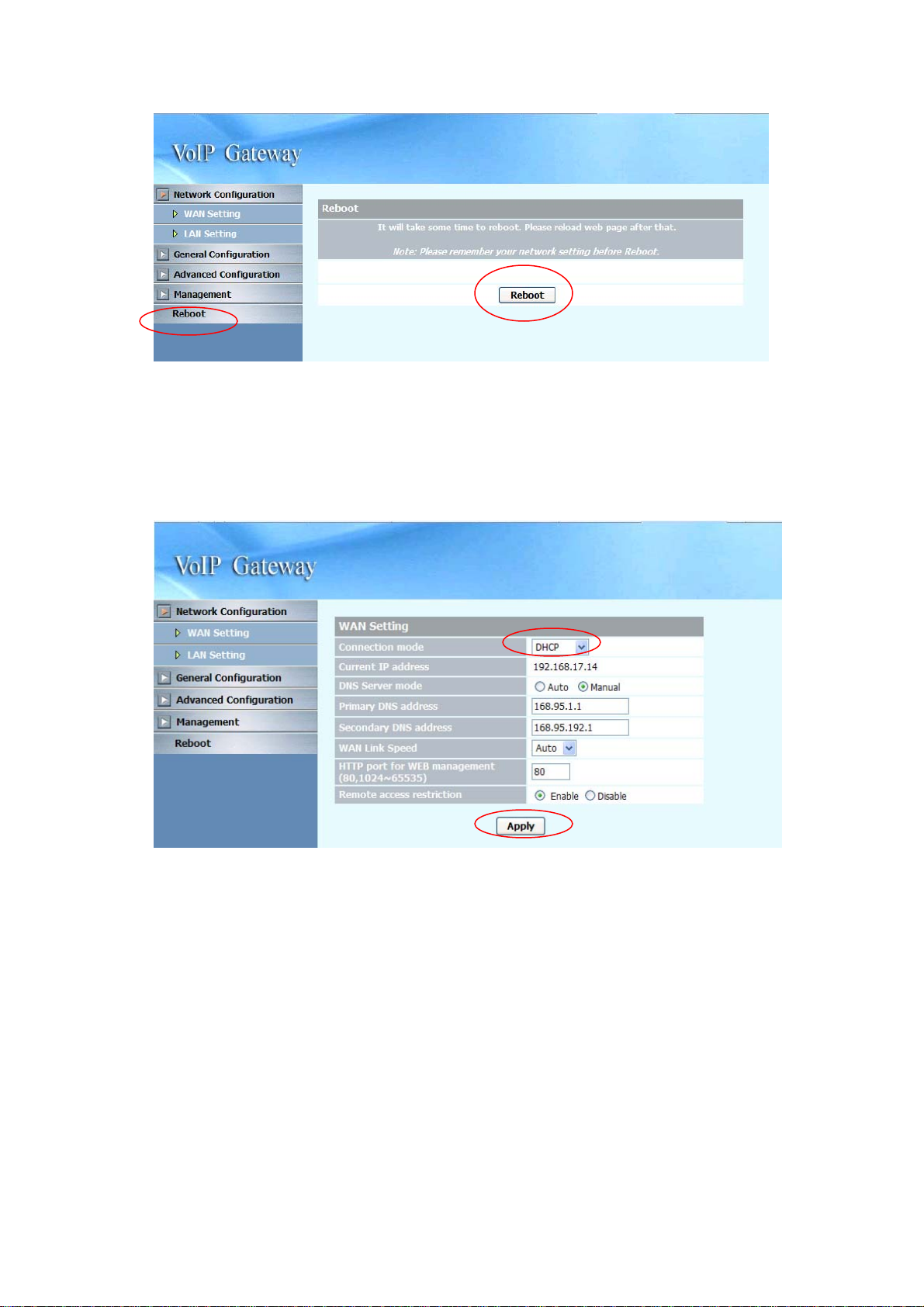
3.4 Rebooting the system
Executing this function will reboot the whole system, when configuration changes
are made to the device, it needs to be rebooted for the changes to take effect (see
figure below).
63
Page 65

4. Operation
4.1 Peer to Peer mode (FXO to FXS)
In this application, the distance of PABX extension is not limited. You can use the
same PABX in two or more branches.
Configuration:
1. Side A (FXO): IP address: 10.1.1.2, number is 2000 to 2008
2. Side B (FXS): IP address: 10.1.1.3, number is 1000 to 1008
Side A : (SP5058A: IP address 10.1.1.2)
General Configuration / SIP Setting
Primary proxy/P2P IP
(Side A--FXO)
Call number configuration
Representative number
(Side A -- FXO)
Specify the destination (Side B) IP Address of
Peer to Peer mode, and specify the port# with
5076.
Enable the representative line
64
Page 66

Side A : (SP5058A : IP address 10.1.1.2)
General Configuration / Line Setting
Line 1~Line 8
(Side A -- FXO)
Please refer to the figure shown above, Enable
all the line and Disable all the register.
Specify the relevant data: Account, number,
password and display name.
1. Press the “Apply” button (at the bottom) after you finish to save changes.
2. Press the “Reboot” button to apply the changes.
65
Page 67

Side B: (MICRONET SP5008A : IP address 10.1.1.3)
General Configuration—SIP Setting
Primary proxy/P2P IP
(Side B)
Call number configuration
Representative number
(Side B)
Line 1~Line 8
(Side B)
Specify the destination (Side A) IP Address of
Peer to Peer mode, and specify the port# with
5076
Enable the representative line
Please refer to the figure shown above, Enable
all the line and Disable all the register.
Specify the relevant data: Account, number,
password and display name.
66
Page 68

Side B: (MICRONET SP5008A: IP address 10.1.1.3)
General Configuration / Line Setting
Line 1~Line 8
(Side B)
1. Press the “Apply” button (at the bottom) after you finish to save changes.
2. Press the “Reboot” button to apply the changes.
Please refer to the figure shown above, Enable
all the line and Disable all the register and call
waiting.
Specify the relevant data: Account, number,
password and display name
67
Page 69

4.2 Peer to Peer mode (FXS to FXS)
Peer A—MICRONET SP5008A / SP5018A / SP5058A ( for example the IP address
is: 192.168.23.14)
Peer B—MICRONET SP5008A / SP5018A / SP5058A ( for example the IP address
is: 192.168.23.58)
Peer A—MICRONET SP5008A / SP5018A / SP5058A ( for example the IP address
is: 192.168.23.14)
68
Page 70

69
Page 71

Peer B—MICRONET SP5008A / SP5018A / SP5058A (for example the IP
address is: 192.168.23.58)
70
Page 72

Primary proxy/P2P IP
(Peer A / Peer B)
Call number configuration
Representative number
(Peer A / Peer B)
Line 1~Line 8
(Peer A / Peer B)
Specify the destination IP Address of Peer to
Peer mode, and specify the port# with 5076.
In this application, we define the Peer to Peer
mode in 2 groups. If you want to make call
to others IP addresses, please refer to the
paragraph 3.3.7 Speed dial setting.
Enable the representative line
Please refer to the figure shown above, Enable
all the line and Disable all the register of two
sides.
Specify the relevant data: Account, number,
password and display name.
3. Press the “Apply” button (at the bottom) after you finish to save changes.
4. Press the “Reboot” button to apply the changes.
71
Page 73

5. Specification
Model
SP5008A
Standard SIPv2 (RFC 3261): Primary and Secondary Proxy, Primary and Secondary
Outbound Proxy
POTS Interface 8 FXS
Ethernet Port
Voice
z 1 x RJ-45 WAN port of 10/100M
z 4 x RJ-45 LAN ports of 10/100M
z Codec: G.711a/mu-law, G.723.1 (6.3K), G.729, G.729.A
z VAD, CNG, and Silence Suppression
z Echo Cancellation (G.165 / G.168)
z Adaptive Jitter Buffer
z Packet Loss Compensation
z Adjustable volume level
DTMF In-band, SIP Info, RFC2833
Telephony
z Caller ID Detection: FSK, DTMF, ETSI (before ringing, between ringing)
z Call hold, Call transfer, Call waiting, Call forward (Unconditional, No
answer, Busy, No Answer+Busy)
PBX Features
z Music on Hold
z Hotline and Waiting Time to Hotline
z Speed Dial and Peer-to-Peer Call
z Anonymous Call
z DND (Do Not Disturb)
z Dial Plan and Digit Manipulation
z Tone Generation/Detection: Ringing Tone, Ring Back Tone, Dial Tone,
Programmable Tone
z CDR (Call Detail Record)
z MWI (Message Waiting Indication)
z FAX over IP: G.711 pass-through, T.38 Fax relay
z Representative number setting
z Support SIP Trunk
z Extension calling among FXS ports
z Direct line (DID) to extension
z Max. 9 registrars (SIP trunk and 8 direct lines)
z Operator (Serial ring on extension) for attendant
Security z HTTP 1.1 basic/digest authentication for WEB access
z MD5 for SIP authentication (RFC 2069/2617)
72
Page 74

Networking
Management
z Password protected for Admin access authority
z PPPoE Client, DHCP Client / Server, NAT, SNTP
z QoS: DiffServ / ToS
z User interface: HTTP and Telnet
z Firmware upgrade via FTP/TFTP/HTTP/Telnet
z Auto Provisioning
Environment
z Operating Temperature: 0 – 45 degree C
z Storage Temperature: 0 – 55 degree C
z Operating Humidity: 10 to 85% (non-condensing)
z Storage Humidity: 10 to 95% (non-condensing)
Power Supply DC 12V, 3A
Emission
CE
FCC Part 15, Class B
Model
Standards
SP5018A
z SIPv2 (RFC 3261): Primary and Secondary Proxy, Primary and
Secondary Outbound Proxy
Interface
Voice Processing
z 1 x RJ-45 WAN port of 10/100M
z 4 x RJ-45 LAN ports of 10/100M
z 4 x RJ-11 FXS ports for connecting with phone set and fax machine
z 4 x RJ-1 1 FXO ports for connecting with PSTN line or PABX’s extension
z Codec: G.711a/mu-law, G.723.1 (6.3K), G.729, G.729.A
Call Features
z VAD, CNG, and Silence Suppression
z Echo Cancellation (G.165 / G.168)
z Adaptive Jitter Buffer
z Packet Loss Compensation
z Adjustable volume level
z DTMF relay: In-band, RFC 2833, SIP Info
z Caller ID Detection: FSK, DTMF, ETSI (before ringing, between ringing)
z Call hold
z Call transfer (blind & consultant)
z Call forward (Unconditional, No answer, Busy)
z MWI (Message Waiting Indication)
z FAX over IP: G.711 pass-through, T.38 Fax relay
z PSTN Lifeline: PSTN bypass if network or system fails
z Detection of disconnect tone, polarity reversal, and loop current drop (zero
voltage) on FXO ports
73
Page 75

Security
Networking
Management
Power Supply
Environment
Dimension
Emission
z HTTP 1.1 basic/digest authentication for WEB access
z MD5 for SIP authentication (RFC 2069/2617)
z Password protected for Admin access authority
z PPPoE Client, DHCP Client / Server, NAT, SNTP
z QoS: DiffServ / ToS
z User interface: HTTP and Telnet
z Firmware upgrade via FTP/TFTP/HTTP/Telnet
z Auto Provisioning
z DC 12V, 3A
z Operating Temperature: 0 – 45 degree C
z Storage Temperature: 0 – 55 degree C
z Operating Humidity: 10 to 85% (non-condensing)
z Storage Humidity: 10 to 95% (non-condensing)
35 × 242 × 160 (mm)
z CE
z FCC Part 15, Class B
Model SP5058A
Standards z SIPv2 (RFC 3261): Primary and Secondary Proxy, Primary and Secondary
Outbound Proxy
Interface z 1 x RJ-45 WAN port of 10/100M
z 4 x RJ-45 LAN ports of 10/100M
z 8 x RJ-1 1 FXO ports for connecting with PSTN line or PABX’s extension
Voice Processing z Codec: G.711a/mu-law, G.723.1 (6.3K), G.729, G.729.A
z VAD, CNG, and Silence Suppression
z Echo Cancellation (G.165 / G.168)
z Adaptive Jitter Buffer
z Packet Loss Compensation
z DTMF relay: In-band, RFC 2833, SIP Info
Call Features z Caller ID Detection: FSK, DTMF, ETSI (before ringing, between ringing)
z Call hold
z Call transfer (blind & consultant)
z Call forward (Unconditional, No answer, Busy)
z FAX over IP: G.711 pass-through, T.38 Fax relay
z Detection of disconnect tone, polarity reversal, and loop current drop (zero
voltage) on FXO ports
Security z HTTP 1.1 basic/digest authentication for WEB access
74
Page 76

z MD5 for SIP authentication (RFC 2069/2617)
z Password protected for Admin access authority
Networking z PPPoE Client, DHCP Client / Server, NAT, SNTP
z QoS: DiffServ / ToS
Management z User interface: HTTP and Telnet
z Firmware upgrade via FTP/TFTP/HTTP/Telnet
z Auto Provisioning
Power Supply z DC 12V, 3A
Environment z Operating Temperature: 0 – 45 degree C
z Storage Temperature: 0 – 55 degree C
z Operating Humidity: 10 to 85% (non-condensing)
z Storage Humidity: 10 to 95% (non-condensing)
Dimension 35 × 242 × 160 (mm)
Emission z CE
z FCC Part 15, Class B
75
 Loading...