

Page 1

Empowered by Innovation
Components Installation
Upgrading from DS2000 to DSX-80/160
If upgrading from DS2000 to DSX-80/160, be sure to carefully review Upgrading
DS2000 to DSX-80/160
(P/N 1093077) prior to the upgrade.
Equipment
Optional
Specifications
and Parts
For additional resources, visit our Technical Support site on the web at
DSX-80/160 Hardware
Manual
P/N 1093096
Rev 2, June 2006
http://www.necdsx.com
Printed in U.S.A
.
01.00.00
.
Page 2

This manual has been developed by NEC Unified Solutions, Inc. It is intended for the use of its customers and service
personnel, and should be read in its entirety before attempting to install or program the system. Any comments or suggestions
for improving this manual would be appreciated. Forward your remarks to:
NEC Unified Solutions, Inc.
4 Forest Parkway
Shelton, CT 06484
www.necunifiedsolutions.com
Nothing contained in this manual shall be deemed to be, and this manual does not constitute, a warranty of, or representation
with respect to, any of the equipment covered. This manual is subject to change without notice and NEC Unified Solutions,
Inc. has no obligation to provide any updates or corrections to this manual. Further, NEC Unified Solutions, Inc. also reserves
the right, without prior notice, to make changes in equipment design or components as it deems appropriate. No
representation is made that this manual is complete or accurate in all respects and NEC Unified Solutions, Inc. shall not be
liable for any errors or omissions. In no event shall NEC Unified Solutions, Inc. be liable for any incidental or consequential
damages in connection with the use of this manual. This document contains proprietary information that is protected by
copyright. All rights are reserved. No part of this document may be photocopied or reproduced without prior written consent
of NEC Unified Solutions, Inc.
©2006 by NEC Unified Solutions, Inc. All Rights Reserved.
Printed in U.S.A.
Page 3

Table of Contents
Table of Contents
Components . . . . . . . . . . . . . . . . . . . . . . . . . . . . . . . . . . . . . . . . . . . . . . . . . . . . . . . . . . 1
DSX Telephones . . . . . . . . . . . . . . . . . . . . . . . . . . . . . . . . . . . . . . . . . . . . . . . . . . . . . . . . 1
22-Button Display Telephone with Speakerphone. . . . . . . . . . . . . . . . . . . . . . . . . . . . . . . . . . . 1
34-Button Backlit Display Telephone with Speakerphone . . . . . . . . . . . . . . . . . . . . . . . . . . . . 1
34-Button Backlit Display Telephone with Full-Duplex Speakerphone . . . . . . . . . . . . . . . . . . 2
34-Button Backlit Super Display Telephone with Half-Duplex Speakerphone . . . . . . . . . . . . . 2
60-Button DSS Console . . . . . . . . . . . . . . . . . . . . . . . . . . . . . . . . . . . . . . . . . . . . . . . . . . . . . . . 2
Single Line Telephones . . . . . . . . . . . . . . . . . . . . . . . . . . . . . . . . . . . . . . . . . . . . . . . . . . . 3
DTH-1-1 Single Line Telephone . . . . . . . . . . . . . . . . . . . . . . . . . . . . . . . . . . . . . . . . . . . . . . . . 3
DTR-1-1 Single Line Telephone . . . . . . . . . . . . . . . . . . . . . . . . . . . . . . . . . . . . . . . . . . . . . . . . 3
DTR-1HM-1 Single Line Telephone . . . . . . . . . . . . . . . . . . . . . . . . . . . . . . . . . . . . . . . . . . . . . 3
DSX Cordless Telephone. . . . . . . . . . . . . . . . . . . . . . . . . . . . . . . . . . . . . . . . . . . . . . . . . . 4
DSX Cordless Lite II . . . . . . . . . . . . . . . . . . . . . . . . . . . . . . . . . . . . . . . . . . . . . . . . . . . . . . . . . 4
Headsets . . . . . . . . . . . . . . . . . . . . . . . . . . . . . . . . . . . . . . . . . . . . . . . . . . . . . . . . . . . . . . . 5
Corded Headsets for DSX Keysets and DTR/DTH SLTs . . . . . . . . . . . . . . . . . . . . . . . . . . . . . 5
NEC / Plantronics Headsets . . . . . . . . . . . . . . . . . . . . . . . . . . . . . . . . . . . . . . . . . . . . . . . . . 5
GN Netcom Headsets . . . . . . . . . . . . . . . . . . . . . . . . . . . . . . . . . . . . . . . . . . . . . . . . . . . . . . 7
Headsets for DSX Cordless Lite II Telephone. . . . . . . . . . . . . . . . . . . . . . . . . . . . . . . . . . . . . . 8
DESI Telephone Label System . . . . . . . . . . . . . . . . . . . . . . . . . . . . . . . . . . . . . . . . . . . . . 9
DESI Labeling Software . . . . . . . . . . . . . . . . . . . . . . . . . . . . . . . . . . . . . . . . . . . . . . . . . . . . . . 9
DESI Telephone Labels . . . . . . . . . . . . . . . . . . . . . . . . . . . . . . . . . . . . . . . . . . . . . . . . . . . . . . . 9
DSX-80/160 Common Equipment. . . . . . . . . . . . . . . . . . . . . . . . . . . . . . . . . . . . . . . . . . 11
DSX-80 4-Slot KSU. . . . . . . . . . . . . . . . . . . . . . . . . . . . . . . . . . . . . . . . . . . . . . . . . . . . . . . . . 11
DSX-160 8-Slot KSU. . . . . . . . . . . . . . . . . . . . . . . . . . . . . . . . . . . . . . . . . . . . . . . . . . . . . . . . 11
DSX-80/160 Power Supply . . . . . . . . . . . . . . . . . . . . . . . . . . . . . . . . . . . . . . . . . . . . . . . . . . . 11
DSX-80/160 CPU . . . . . . . . . . . . . . . . . . . . . . . . . . . . . . . . . . . . . . . . . . . . . . . . . . . . . . 12
DSX-80/160 CPU Card . . . . . . . . . . . . . . . . . . . . . . . . . . . . . . . . . . . . . . . . . . . . . . . . . . . . . . 12
DSX-80/160 Station Cards . . . . . . . . . . . . . . . . . . . . . . . . . . . . . . . . . . . . . . . . . . . . . . . 13
DSX-80/160 16 Port Digital Station (16ESIU) Card . . . . . . . . . . . . . . . . . . . . . . . . . . . . . . . . 13
DSX-80/160 16 Port Analog Station (16SLIU) Card with HV Message Waiting. . . . . . . . . . 13
DSX-80/160 8 Port Analog Station (8SLIU) Card with HV Message Waiting. . . . . . . . . . . . 14
DSX-80/160 Line Cards . . . . . . . . . . . . . . . . . . . . . . . . . . . . . . . . . . . . . . . . . . . . . . . . . 15
DSX-80/160 T1/E1/PRI Line Card . . . . . . . . . . . . . . . . . . . . . . . . . . . . . . . . . . . . . . . . . . . . . 15
DSX-80/160 16 Port CO Line (16COIU) Card with Caller ID . . . . . . . . . . . . . . . . . . . . . . . . 15
DSX-80/160 8 Port CO Line (8COIU) Card with Caller ID . . . . . . . . . . . . . . . . . . . . . . . . . . 16
IntraMail . . . . . . . . . . . . . . . . . . . . . . . . . . . . . . . . . . . . . . . . . . . . . . . . . . . . . . . . . . . . . 17
DSX IntraMail 8 x 16. . . . . . . . . . . . . . . . . . . . . . . . . . . . . . . . . . . . . . . . . . . . . . . . . . . . . . . . 17
DSX IntraMail 4 x 8. . . . . . . . . . . . . . . . . . . . . . . . . . . . . . . . . . . . . . . . . . . . . . . . . . . . . . . . . 17
Miscellaneous Cards and Optional Equipment . . . . . . . . . . . . . . . . . . . . . . . . . . . . . . . . 18
DSX Analog Door Box . . . . . . . . . . . . . . . . . . . . . . . . . . . . . . . . . . . . . . . . . . . . . . . . . . . . . . 18
DSX 2PGDAD Module . . . . . . . . . . . . . . . . . . . . . . . . . . . . . . . . . . . . . . . . . . . . . . . . . . . . . . 18
System Configuration . . . . . . . . . . . . . . . . . . . . . . . . . . . . . . . . . . . . . . . . . . . . . . . . . . . 19
DSX-80/160 System Load Factor . . . . . . . . . . . . . . . . . . . . . . . . . . . . . . . . . . . . . . . . . . . . . . 19
DSX-80/160 Hardware Manual
Table of Contents ◆ i
Page 4

ii ◆
Table of Contents
Installation . . . . . . . . . . . . . . . . . . . . . . . . . . . . . . . . . . . . . . . . . . . . . . . . . . . . . . . . . . 21
System Preparation . . . . . . . . . . . . . . . . . . . . . . . . . . . . . . . . . . . . . . . . . . . . . . . . . . . . . 21
Installing the Main Equipment Cabinet . . . . . . . . . . . . . . . . . . . . . . . . . . . . . . . . . . . . . . 22
Grounding the Cabinet. . . . . . . . . . . . . . . . . . . . . . . . . . . . . . . . . . . . . . . . . . . . . . . . . . . 26
Installing the Power Supply . . . . . . . . . . . . . . . . . . . . . . . . . . . . . . . . . . . . . . . . . . . . . . . 29
Installing Cards . . . . . . . . . . . . . . . . . . . . . . . . . . . . . . . . . . . . . . . . . . . . . . . . . . . . . . . . 30
Connecting Extensions and Setting Up the Telephone . . . . . . . . . . . . . . . . . . . . . . . . . . 41
Connecting Lines . . . . . . . . . . . . . . . . . . . . . . . . . . . . . . . . . . . . . . . . . . . . . . . . . . . . . . . 47
Powering Up the System . . . . . . . . . . . . . . . . . . . . . . . . . . . . . . . . . . . . . . . . . . . . . . . . . 48
Finishing the Installation . . . . . . . . . . . . . . . . . . . . . . . . . . . . . . . . . . . . . . . . . . . . . . . . . 52
Unpacking . . . . . . . . . . . . . . . . . . . . . . . . . . . . . . . . . . . . . . . . . . . . . . . . . . . . . . . . . . . . . . . . 21
Before Installing. . . . . . . . . . . . . . . . . . . . . . . . . . . . . . . . . . . . . . . . . . . . . . . . . . . . . . . . . . . . 21
Site Requirements. . . . . . . . . . . . . . . . . . . . . . . . . . . . . . . . . . . . . . . . . . . . . . . . . . . . . . . . . . . 21
Planning the Installation. . . . . . . . . . . . . . . . . . . . . . . . . . . . . . . . . . . . . . . . . . . . . . . . . . . . . . 22
Removing the Cover. . . . . . . . . . . . . . . . . . . . . . . . . . . . . . . . . . . . . . . . . . . . . . . . . . . . . . . . . 23
Unpacking the Wall Mount Bracket. . . . . . . . . . . . . . . . . . . . . . . . . . . . . . . . . . . . . . . . . . . . . 24
Mounting the Wall Mount Bracket . . . . . . . . . . . . . . . . . . . . . . . . . . . . . . . . . . . . . . . . . . . . . 24
Hanging the Cabinet. . . . . . . . . . . . . . . . . . . . . . . . . . . . . . . . . . . . . . . . . . . . . . . . . . . . . . . . . 25
Removing the Right Side Panel . . . . . . . . . . . . . . . . . . . . . . . . . . . . . . . . . . . . . . . . . . . . . . . . 26
Attaching the Ground Wire . . . . . . . . . . . . . . . . . . . . . . . . . . . . . . . . . . . . . . . . . . . . . . . . . . . 27
Installing the RFI Suppressor Assembly . . . . . . . . . . . . . . . . . . . . . . . . . . . . . . . . . . . . . . . . . 28
Power Supply Installation . . . . . . . . . . . . . . . . . . . . . . . . . . . . . . . . . . . . . . . . . . . . . . . . . . . . 29
On-Premises Extensions. . . . . . . . . . . . . . . . . . . . . . . . . . . . . . . . . . . . . . . . . . . . . . . . . . . . . . 30
Hot Insertion of Cards . . . . . . . . . . . . . . . . . . . . . . . . . . . . . . . . . . . . . . . . . . . . . . . . . . . . . . . 30
Installing the CPU . . . . . . . . . . . . . . . . . . . . . . . . . . . . . . . . . . . . . . . . . . . . . . . . . . . . . . . . . . 30
Installing the 16ESIU Digital Station Cards . . . . . . . . . . . . . . . . . . . . . . . . . . . . . . . . . . . . . . 31
Connecting 16ESIU Cards . . . . . . . . . . . . . . . . . . . . . . . . . . . . . . . . . . . . . . . . . . . . . . . . . 32
Installing 16SLIU and 8SLIU Analog Station Cards. . . . . . . . . . . . . . . . . . . . . . . . . . . . . . . . 33
Connecting 16SLIU and 8SLIU Cards. . . . . . . . . . . . . . . . . . . . . . . . . . . . . . . . . . . . . . . . 34
Installing 16COIU and 8COIU Analog Line Cards . . . . . . . . . . . . . . . . . . . . . . . . . . . . . . . . . 35
Connecting 16COIU and 8COIU Cards . . . . . . . . . . . . . . . . . . . . . . . . . . . . . . . . . . . . . . . 36
Installing T1/E1/PRI Cards . . . . . . . . . . . . . . . . . . . . . . . . . . . . . . . . . . . . . . . . . . . . . . . . . . . 37
Connecting the T1/E1/PRI Card. . . . . . . . . . . . . . . . . . . . . . . . . . . . . . . . . . . . . . . . . . . . . 38
Securing the Cables . . . . . . . . . . . . . . . . . . . . . . . . . . . . . . . . . . . . . . . . . . . . . . . . . . . . . . . . . 39
Making Your Own Cables . . . . . . . . . . . . . . . . . . . . . . . . . . . . . . . . . . . . . . . . . . . . . . . . . . . . 39
Making Your Own Installation Cables. . . . . . . . . . . . . . . . . . . . . . . . . . . . . . . . . . . . . . . . 39
Making a T1/E1/PRI Crossover Cable . . . . . . . . . . . . . . . . . . . . . . . . . . . . . . . . . . . . . . . . 40
Connecting Extensions. . . . . . . . . . . . . . . . . . . . . . . . . . . . . . . . . . . . . . . . . . . . . . . . . . . . . . . 41
Installing the DSX Keyset Handset and Line Cord.. . . . . . . . . . . . . . . . . . . . . . . . . . . . . . 42
Installing the DSX Keyset Optional Headset . . . . . . . . . . . . . . . . . . . . . . . . . . . . . . . . . . . 42
Installing the DSS Console Line Cord . . . . . . . . . . . . . . . . . . . . . . . . . . . . . . . . . . . . . . . . 43
Keyset and DSS Console Two Position Angle Adjustment. . . . . . . . . . . . . . . . . . . . . . . . . . . 44
Removing the Faceplate . . . . . . . . . . . . . . . . . . . . . . . . . . . . . . . . . . . . . . . . . . . . . . . . . . . . . . 45
Connecting Analog Lines. . . . . . . . . . . . . . . . . . . . . . . . . . . . . . . . . . . . . . . . . . . . . . . . . . . . . 47
Connecting T1 Lines . . . . . . . . . . . . . . . . . . . . . . . . . . . . . . . . . . . . . . . . . . . . . . . . . . . . . . . . 47
Before Powering Up. . . . . . . . . . . . . . . . . . . . . . . . . . . . . . . . . . . . . . . . . . . . . . . . . . . . . . . . . 48
System LEDs . . . . . . . . . . . . . . . . . . . . . . . . . . . . . . . . . . . . . . . . . . . . . . . . . . . . . . . . . . . . . . 49
Power Supply LEDs . . . . . . . . . . . . . . . . . . . . . . . . . . . . . . . . . . . . . . . . . . . . . . . . . . . . . . 49
CPU Card LEDs . . . . . . . . . . . . . . . . . . . . . . . . . . . . . . . . . . . . . . . . . . . . . . . . . . . . . . . . . 49
Digital Station (ESIU), Analog Station (SLIU), and Analog Line (COIU) Card LEDs . . 50
T1/E1/PRI Card LEDs . . . . . . . . . . . . . . . . . . . . . . . . . . . . . . . . . . . . . . . . . . . . . . . . . . . . 51
Table of Contents
DSX-80/160 Hardware Manual
Page 5

Table of Contents
Reinstalling the Side Panel. . . . . . . . . . . . . . . . . . . . . . . . . . . . . . . . . . . . . . . . . . . . . . . . . . . . 52
Reinstalling the Front Cover . . . . . . . . . . . . . . . . . . . . . . . . . . . . . . . . . . . . . . . . . . . . . . . . . . 53
Resetting and Initializing the System . . . . . . . . . . . . . . . . . . . . . . . . . . . . . . . . . . . . . . . 54
Resetting the System . . . . . . . . . . . . . . . . . . . . . . . . . . . . . . . . . . . . . . . . . . . . . . . . . . . . . . . . 54
Initializing the System . . . . . . . . . . . . . . . . . . . . . . . . . . . . . . . . . . . . . . . . . . . . . . . . . . . . . . . 55
Upgrading the System Software . . . . . . . . . . . . . . . . . . . . . . . . . . . . . . . . . . . . . . . . . . . 56
Upgrade System Software . . . . . . . . . . . . . . . . . . . . . . . . . . . . . . . . . . . . . . . . . . . . . . . . . . . . 56
Installing Optional Equipment . . . . . . . . . . . . . . . . . . . . . . . . . . . . . . . . . . . . . . . . . . 57
Installing IntraMail . . . . . . . . . . . . . . . . . . . . . . . . . . . . . . . . . . . . . . . . . . . . . . . . . . . . . 57
Setting Up IntraMail for the First Time . . . . . . . . . . . . . . . . . . . . . . . . . . . . . . . . . . . . . . . . . . 57
Installing a DSX Analog Door Box and 2PGDAD Module . . . . . . . . . . . . . . . . . . . . . . 58
Connecting a DSX Analog Door Box to the 2PGDAD Module . . . . . . . . . . . . . . . . . . . . . . . 58
Preparation . . . . . . . . . . . . . . . . . . . . . . . . . . . . . . . . . . . . . . . . . . . . . . . . . . . . . . . . . . . . . 58
Connecting Door Boxes and Relays. . . . . . . . . . . . . . . . . . . . . . . . . . . . . . . . . . . . . . . . . . 59
Mounting the 2PGDAD Module and Connecting to the System . . . . . . . . . . . . . . . . . . . . 60
External Paging . . . . . . . . . . . . . . . . . . . . . . . . . . . . . . . . . . . . . . . . . . . . . . . . . . . . . . . . 61
Installing External Paging . . . . . . . . . . . . . . . . . . . . . . . . . . . . . . . . . . . . . . . . . . . . . . . . . . . . 61
Music Source . . . . . . . . . . . . . . . . . . . . . . . . . . . . . . . . . . . . . . . . . . . . . . . . . . . . . . . . . . 62
Installing a Music Source. . . . . . . . . . . . . . . . . . . . . . . . . . . . . . . . . . . . . . . . . . . . . . . . . . . . . 62
Power Failure Telephone . . . . . . . . . . . . . . . . . . . . . . . . . . . . . . . . . . . . . . . . . . . . . . . . . 63
Power Failure Cut-Through . . . . . . . . . . . . . . . . . . . . . . . . . . . . . . . . . . . . . . . . . . . . . . . . . . . 63
Wall Mounting . . . . . . . . . . . . . . . . . . . . . . . . . . . . . . . . . . . . . . . . . . . . . . . . . . . . . . . . . 64
Reversing the Handset Hanger . . . . . . . . . . . . . . . . . . . . . . . . . . . . . . . . . . . . . . . . . . . . . . . . . 64
Wall Mounting a Keyset. . . . . . . . . . . . . . . . . . . . . . . . . . . . . . . . . . . . . . . . . . . . . . . . . . . . . . 65
Wall Mounting a Keyset on a Standard Wall Plate . . . . . . . . . . . . . . . . . . . . . . . . . . . . . . 65
Wall Mounting a Keyset Directly on the Wall . . . . . . . . . . . . . . . . . . . . . . . . . . . . . . . . . . 66
Wall Mounting a DSS Console . . . . . . . . . . . . . . . . . . . . . . . . . . . . . . . . . . . . . . . . . . . . . . . . 67
Wall Mounting a DSS Console on a Standard Wall Plate . . . . . . . . . . . . . . . . . . . . . . . . . 67
Wall Mounting a DSS Console Directly on the Wall. . . . . . . . . . . . . . . . . . . . . . . . . . . . . 68
Keyset Self Test . . . . . . . . . . . . . . . . . . . . . . . . . . . . . . . . . . . . . . . . . . . . . . . . . . . . . . . . 69
Testing the Keyset . . . . . . . . . . . . . . . . . . . . . . . . . . . . . . . . . . . . . . . . . . . . . . . . . . . . . . . . . . 69
Connecting a PC to the System . . . . . . . . . . . . . . . . . . . . . . . . . . . . . . . . . . . . . . . . . . . . 70
Connections for PC Programming (System Administrator) and SMDR . . . . . . . . . . . . . . . . . 70
Specifications and Parts . . . . . . . . . . . . . . . . . . . . . . . . . . . . . . . . . . . . . . . . . . . . . . . 71
Specifications. . . . . . . . . . . . . . . . . . . . . . . . . . . . . . . . . . . . . . . . . . . . . . . . . . . . . . . . . . 71
Parts List . . . . . . . . . . . . . . . . . . . . . . . . . . . . . . . . . . . . . . . . . . . . . . . . . . . . . . . . . . . . . 76
DSX-80/160 Hardware Manual
Table of Contents ◆ iii
Page 6

Table of Contents
iv ◆
Table of Contents
DSX-80/160 Hardware Manual
Page 7

DSX Telephones
DSX Telephones
Components
Components
DSX Telephones
22-Button Display Telephone with Speakerphone
P/Ns 1090020 (Black) and 1090025 (White)
Display: 3 line x 24 character Speakerphone: Built-in, half-duplex
Soft Keys: 4 Wall Mount: Built-in
Feature Keys: 12 Angle Adjustment: 2 position built-in
Fixed Function Keys: 12 Backlit: No
At a Glance
34-Button Backlit Display Telephone with Speakerphone
At a Glance
Speed Dial Bin Keys: 10 Dual LEDs: Yes
Headset jack: RJ-10 built-in
The 22-Button Display Telephone features a large 3 line-by-24 character alphanumeric display with 4 Interactive Soft Keys for intuitive feature access. It also provides 10 Personal Speed Dial bin keys, 12 programmable
Feature Keys and 12 fixed function keys for streamlined operation. Additionally, this telephone offers a headset
jack and built-in speakerphone. Unique features include dual LEDs, a Ring/Message Lamp (to show ringing,
Caller ID, and voice mail messages), built-in wall mounting, and an innovative two position angle adjustment.
P/Ns 1090021 (Black) and 1090026 (White)
Display: 3 line x 24 character Speakerphone: Built-in, half-duplex
Soft Keys: 4 Wall Mount: Built-in
Feature Keys: 24 Angle Adjustment: 2 position built-in
Fixed Function Keys: 12 Backlit: Yes
Speed Dial Bin Keys: 10 Dual LEDs: Yes
Headset jack: RJ-10 built-in
The 34-Button Display Telephone features a large 3 line-by-24 character backlit alphanumeric display with
4 Interactive Soft Keys for intuitive feature access. It also provides 10 Personal Speed Dial bin keys, 24 programmable Feature Keys and 12 fixed function keys for streamlined operation. Additionally, this telephone
offers a backlit keypad, a headset jack, and built-in speakerphone. Unique features include dual LEDs, a
Ring/Message Lamp (to show ringing, Caller ID, and voice mail messages), built-in wall mounting, and an
innovative two position angle adjustment.
DSX-80/160 Hardware Manual
Components ◆ 1
Page 8

2 ◆
DSX Telephones
34-Button Backlit Display Telephone with Full-Duplex Speakerphone
P/Ns 1090022 (Black) and 1090027 (White)
Display: 3 line x 24 character Speakerphone: Built-in, full-duplex
Soft Keys: 4 Wall Mount: Built-in
Feature Keys: 24 Angle Adjustment: 2 position built-in
Fixed Function Keys: 12 Backlit: Yes
At a Glance
Speed Dial Bin Keys: 10 Dual LEDs: Yes
Headset jack: RJ-10 built-in
This feature-rich 34-Button Display Telephone features a large 3 line-by-24 character backlit alphanumeric
display with 4 Interactive Soft Keys for intuitive feature access. It also provides 10 Personal Speed Dial bin
keys, 24 programmable Feature Keys and 12 fixed function keys for streamlined operation. Additionally, this
telephone offers a built-in full duplex speakerphone (with no external speaker or microphone required), a
backlit keypad, and a headset jack. Unique features include dual LEDs, a Ring/Message Lamp (to show
ringing, Caller ID, and voice mail messages), built-in wall mounting, and an innovative two position angle
adjustment.
34-Button Backlit Super Display Telephone with Half-Duplex Speakerphone
P/Ns 1090030 (Black) and 1090031 (White)
Display: 9 line x 24 character Speakerphone: Built-in, hald-duplex
Soft Keys: 12 Wall Mount: Built-in
Feature Keys: 24 Angle Adjustment: 2 position built-in
Fixed Function Keys: 12 Backlit: Yes
At a Glance
Speed Dial Bin Keys: 10 Dual LEDs: Yes
Headset jack: RJ-10 built-in
The Super Display Telephone is the system’s most sophisticated telephone instrument. It features a large 9
line-by-24 character backlit alphanumeric display with 12 Interactive Soft Keys for intuitive feature access.
It also provides 10 Personal Speed Dial bin keys, 24 programmable Feature Keys and 12 fixed function keys
for streamlined operation. Additionally, this telephone offers a built-in half duplex speakerphone (with no
external speaker or microphone required), a backlit keypad, and a headset jack. Unique features include dual
LEDs, a Ring/Message Lamp (to show ringing, Caller ID, and voice mail messages), built-in wall mounting,
and an innovative two position angle adjustment.
60-Button DSS Console
P/Ns 1090024 (Black) and 1090029 (White)
Feature Keys: 60 Wall Mount: Built-in
Fixed Function Keys: 3 Angle Adjustment: 2 position built-in
Dual LEDs: No
At a Glance
The 60-Button DSS Console provides a display keyset with a
button access to extensions, trunks, and selected system features. Enhanced by Answer, Release, and
Transfer fixed function keys, the 60-Button DSS Console is a great time saver for users that do a lot of call
processing (such as operators or dispatchers). By default, the DSS Console is set up with Hotline keys to
extensions and 14 feature keys for quick access to Page, Park and the system Night Mode
Note: DSX80/160 supports DS1000/2000 telephones if the system has a DSTU Card (P/N 80021A) installed.
Components
60-button Busy Lamp Field (BLF) and one-
DSX-80/160 Hardware Manual
Page 9

Single Line Telephones
Single Line Telephones
DTH-1-1 Single Line Telephone
P/N 780034 (Black)
Fixed Function Keys: 5 Message Waiting: Yes
Speed Dial Bin Keys: 4 Ring/Message Waiting Lamp: Yes
Selectable Ring Tones: Yes Wall Mount: Built-in
At a Glance
The DTH-1-1 is a cost-effective analog single line telephone that offers 5 fixed feature keys, 4 Speed Dial
bin keys and Message Waiting. The built-in Message Waiting lamp will flash for incoming calls or when the
user has a message. To simplify working in groups, The DTH-1-1 provides 3 selectable ring tones.
DTR-1-1 Single Line Telephone
P/Ns 780020 (Black) and 780021 (White)
Fixed Function Keys: 5 Message Waiting: Yes
Speed Dial Bin Keys: None Ring/Message Waiting Lamp: No
Selectable Ring Tones: Yes Wall Mount: Built-in
At a Glance
Handsfree Monitor: No
The DTR-1-1 is a stylish yet rugged analog single line telephone with 5 fixed feature keys and Message
Waiting. Similar to the DTH-1-1, the DTR-1-1 has a built in Message Waiting lamp that will flash for incoming calls or when the user has a message. The DTR-1-1 offers programmable ring pitch and volume. Built-in
wall mounting and a bridged data jack for connecting a modem or answering machine are standard.
Components
DTR-1HM-1 Single Line Telephone
P/Ns 780025 (Black) and 780026 (White)
Fixed Function Keys: 7 Message Waiting: Yes
Speed Dial Bin Keys: 8 Ring/Message Waiting Lamp: Yes
Selectable Ring Tones: Yes Wall Mount: Built-in
At a Glance
Handsfree Monitor: Yes
The DTR-1HM-1 provides all the features of the DTR-1-1 in addition to two additional fixed function keys
(for Hold and Speaker/Monitor) and 8 Speed Dial bin keys. For convenient on-hook dialing and call monitor,
the DTR-1HM-1 also offers Handsfree Monitor.
DSX-80/160 Hardware Manual
Components ◆ 3
Page 10

DSX Cordless Telephone
DSX Cordless Telephone
DSX Cordless Lite II
P/N 730087
Display: 2 line x 16 character Transmission: 900 MHz Narrow Band FM
Status Icons: 4 Range: 350 feet (site dependent)
Feature Keys: 4 Max Units Per Site: 30 (12 in close proximity)
Fixed Function Keys: 8 Battery Life: Up to 7 hours talk time
At a Glance
Channels: 30
The DSX Cordless Lite II Telephone (P/N 730087) is a 900 Mhz digital narrow band FM cordless telephone
that provides mobility, flexibility and convenience for those who spend much of the workday away from
their desk. Fully integrated with the DSX system, the DSX Cordless Lite II Telephone offers many standard
features such as Call Forwarding, Call Coverage, Hotline, and Voice Mail. Complemented by 4 fully programmable function keys (with LEDs), the DSX Cordless Lite II Telephone achieves a whole new level of
convenience and mobility. An easy-to-read 16-character by 2-line LCD display (with four status icons), volume controls, a rechargeable Nickel Metal Hydride Battery Pack, and a handy belt clip round out the elegant
and affordable DSX Cordless Lite II Telephone.
4 ◆
The Cordless II Lite Telephone includes the following:
• Base Unit
• Base Unit AC Adaptor (P/N 630618)
• Base Wall Mount Bracket (P/N 730608)
• Base Line Cord
• Handset
• Handset Charger (P/N 730632)
• Handset Charger AC Adaptor (P/N 730619)
• Handset Charger Wall Mount Bracket (P/N
730633)
• Handset Battery (P/N 730631)
• Belt Clip (P/N 730634)
Components
DSX-80/160 Hardware Manual
Page 11

Headsets
Headsets
Corded Headsets for DSX Keysets and DTR/DTH SLTs
The following corded headsets are compatible with DSX keysets and the DTR/DTH single line telephones.
Check with your supplier for their latest offerings.
NEC / Plantronics Headsets
NEC / Plantronics Amplified Headsets
NEC P/N
Description Style Microphone Type
Voice Tube P31
- Polaris Starset In-the-Ear
Noise Canceling P31N
750631
Voice Tube P41
Polaris Mirage On-the-Ear
- Noise Canceling P41N
750632
Voice Tube P51
Polaris Supra Monaural Over-the-Head
750636 Noise Canceling P51N
-
Voice Tube P61
Polaris Supra Binaural Over-the-Head
750633 Noise Canceling P61N
750630
Voice Tube P81
Polaris TriStar In-the-Ear
- Noise Canceling P81N
750634
Voice Tube P91
Polaris Encore Monaural Over-the-Head
- Noise Canceling P91N
- Polaris Encore Binaural Over-the-Head Voice Tube P101
760635 Noise Canceling P101N
- DuoSet Convertible
Over-the-Head,
On-the-Ear
Voice Tube P141
Noise Canceling P141N
Voice Tube P151
- DuoPro On-the-Ear
Noise Canceling P151N
Voice Tube P161
- DuoPro Over-the-Head
Noise Canceling P161N
- DuoPro Convertible
- DuoPro Convertible
Over-the-Head,
Over-the-Head,
Voice Tube P171
Noise Canceling P171N
- DuoPro Behind-the-Head Voice Tube P181
- DuoPro Behind-the-Head Noise Canceling P181N
750643 Polaris/SupraPlus Monaural
Voice Tube P251
Over-the-Head
750644 Polaris/SupraPlus NC Monaural Noise Canceling P251N
- Polaris/SupraPlus NC Binaural
Voice Tube P261
Over-the-Head
750645 Polaris/SupraPlus NC Binaural Noise Canceling P261N
Voice Tube P351
- SupraPlus SL Monaural Over-the-Head
Noise Canceling P351N
Voice Tube P361
- SupraPlus SL Binaural Over-the-Head
Noise Canceling P361N
Plantronics Model
Components
Number
DSX-80/160 Hardware Manual
Components ◆ 5
Page 12

Headsets
6 ◆
NEC / Plantronics Non-Amplified Headsets
NEC P/N
Description Style Microphone Type
- StarSet In-the-Ear
- Mirage On-the-Ear
- Supra Monaural Over-the-Head
- Supra Binaural Over-the-Head
- TriStar In-the-Ear
- Encore Monaural Over-the-Head
- Encore Binaural Over-the-Head
- Freehand Monaural In-the-Ear
- DuoSet Convertible
- DuoPro On-the-Ear
- DuoPro Over-the-Head
- DuoPro Convertible
- DuoPro Behind-the-Head
- SupraPlus Monaural Over-the-Head
- SupraPlus Binaural Over-the-Head
- SupraPlus SL Monaural Over-the-Head
- SuproPlus SL Binaural Over-the-Head
1
Requires Vista M12 Amplifier and Handset/Headset Switch
Over-the-Head,
On-the-Ear
Over-the-Head,
On-the-Ear
1
Plantronics Model
Number
Voice Tube H31
Noise Canceling H31N
Voice Tube H41
Noise Canceling H41N
Voice Tube H51
Noise Canceling H51N
Voice Tube H61
Noise Canceling H61N
Voice Tube H81
Noise Canceling H81N
Voice Tube H91
Noise Canceling H91N
Voice Tube H101
Noise Canceling H101N
Voice Tube H131
Noise Canceling H131N
Voice Tube H141
Noise Canceling H141N
Voice Tube H151
H151N
Voice Tube H161
Noise Canceling H161N
Voice Tube H171
Noise Canceling H171N
Voice Tube H181
Noise Canceling H181N
Voice Tube H251
Noise Canceling H251N
Voice Tube H261
Noise Canceling H261N
Voice Tube H351
Noise Canceling H351N
Voice Tube H361
Noise Canceling H361N
Components
DSX-80/160 Hardware Manual
Page 13

GN Netcom Headsets
Headsets
1
Model Number
GN Netcom Non-Amplified Headsets
Description Microphone Type Style
GN 2110 STD01 2100 Sound Tube Monaural Sound-Tube Over-the-Head
GN 2120 NCD01 2100 Flex Monaural Noise-Canceling Over-the-Head
GN 2115 STD01 2100 SoundTube Binaural Sound-Tube Over-the-Head
GN 2125 NCD01 2100 Flex Binaural Noise-Canceling Over-the-Head
GN 2117 STD01 2100 SoundTube Monaural Sound-Tube On-the-Ear
GN 2127 NCD01 2100 Flex Monaural Noise-Canceling On-the-Ear
GN 2110 ST 2100 SoundTube Monaural Sound-Tube Over-the-Head
GN 2120 NC 2100 Flex Monaural Noise-Canceling Over-the-Head
GN 2115 ST 2100 SoundTube Binaural Sound-Tube Over-the-Head
GN 2125 NC 2100 Flex Binaural Noise-Canceling Over-the-Head
GN 2127 ST 2100 SoundTube Monaural Sound-Tube On-the-Ear
GN 2127 NC 2100 Flex Monaural Noise-Canceling On-the-Ear
405-SF Surefit Monaural Voice-Tube
405-FLEX-SF Surefit Monaural Noise-Canceling
405-UNC-SF Surefit Monaural Noise-canceling
3-Way Convertible:
Over-the-Head, Ear-
hook, Earloops
ADP-I ADDvantage Plus Monaural Noise-Canceling Over-the-Head
ADP-II ADDvantage Plus Binaural Noise-Canceling Over-the-Head
GN 2200 2200 Omega Monaural Noise-Canceling Over-the-Head
GN 2225 2200 Omega Binaural Noise-Canceling Over-the-Head
OG-I Orator-G Monaural Noise-Canceling Over-the-Head
OG-II Orator-G Binaural Noise-Canceling Over-the-Head
Contour LX-G Contour LX-G Monaural Noise-Canceling On-the-Ear
Stratus Ultra-G Stratus Ultra-G Monaural Noise-Canceling On-the-Ear
805-Flex 805-Flex Binaural Noise-Canceling
1
Requires GN8000 MPA Amplifier and Headset Switch.
Under-the-Chin or
Behind-the-Neck
Components
DSX-80/160 Hardware Manual
Components ◆ 7
Page 14

Headsets
Headsets for DSX Cordless Lite II Telephone
P/N 750637 (M175) P/N 750642 (MX150)
At a Glance
The following headsets are available for the DSX Cordless Lite II Telephone:
• M175 Headband Style (P/N 750637)
• MX150 Earloop Style (P/N 750642)
8 ◆ Components DSX-80/160 Hardware Manual
Page 15

DESI Telephone Label System
DESI Telephone Label System
DESI Labeling Software
At a Glance
DESI Labeling Software is a Windows-compatible application for printing customized key data on specially
designed DESI telephone labels. Use DESI Labeling Software to create quick, professional custom labels
that can be printed on virtually any office ink jet or laser printer. DESI Labeling Software features:
• Automatic extension numbering
• Label templates that can be saved for later use
• Copy and paste functions
• Perforated and die cut labels for a perfect fit
• Choice of fonts and font colors
• Space for incorporating company logo
• User-printable background graphics (using DESI Preprint)
DESI labeling software is provided on the DSX System Document CD included with each telephone system.
Components
DESI Labeling Software
DESI Telephone Labels
Labels for DSX Telephones Labels for NEC Single Line Telephones
At a Glance
The following DESI labels are available for DSX telephones.
• For standard “replacement” applications:
- 22-Button Display Standard
- 34-Button Display Standard
- 34-Button Super Display Standard
- 60-Button DSS Console Standard
The following DESI labels are available for the NEC analog single line telephones.
• For DTR-1-1
- Black (P/N 780400)
- Metallic green (P/N 780401)
- Metallic silver (P/N 780402)
- Lime green (P/N 780403)
- Preprint (blank) (P/N 780459)
DSX-80/160 Hardware Manual Components ◆ 9
Page 16

DESI Telephone Label System
• For DTR-1HM-1
- Black (P/N 780404)
- Metallic green (P/N 780405)
- Metallic silver (P/N 780406)
- Lime green (P/N 780407)
- Preprint (blank) (P/N 780460)
• For DTH-1-1
- Metallic silver (P/N 780450)
10 ◆ Components DSX-80/160 Hardware Manual
Page 17

DSX-80/160 Common Equipment
DSX-80/160 Common Equipment
DSX-80 4-Slot KSU
P/N 1090002
Slots: 4 Analog extensions (max.): 48
Ports: 80 Analog lines (max): 48
Digital extensions (max.): 32 Digital (T1) lines (max.): 64
• Capacities determined by System Load Factor.
At a Glance
• Always install a 16ESIU Card in the first universal slot.
The DSX-80 4-Slot KSU contains the CPU, 4 universal card slots and the system’s power supply. It provides
80 ports. It is wall-mountable, has a flip off cover and removable side panel for easy access. The cabinet has
a handy translucent panel in the cover that allows you to get essential system status and troubleshooting
information at a glance, without removing the cover.
DSX-160 8-Slot KSU
P/N 1090003
Slots: 8 Analog extensions (max.): 112
Ports: 160 Analog lines (max): 64
Digital extensions (max.): 96 Digital (T1) lines (max.): 64
• Capacities determined by System Load Factor.
At a Glance
• Always install a 16ESIU Card in the first universal slot.
• Install one power supply for every two 16ESIU Cards.
Components
The DSX-160 8-Slot KSU contains the CPU slot, 8 universal card slots and up to 3 system power supplies
(depending on Load Factor requirements). It provides 160 ports. Just like the DSX-80 4-Slot KSU, the DSX160 is wall-mountable, has a flip off cover and removable side panel for easy access. The DSX-160 also has
a translucent panel in the cover for getting essential system status and troubleshooting at a glance
DSX-80/160 Power Supply
P/N 1091008
DSX-80 Qty: 1 DSX-160 Qty: 3 (max.)
• Quantity required in DSX-160 determined by System Load Factor.
• In DSX-160, Install one power supply for every two 16ESIU Cards.
At a Glance
The power supply provides the various DC voltages required to power the DSX-80/160 Cards. The DSX-80
4-Slot KSU requires a single power supply. The DSX-160 8-Slot KSU requires up to 3 power supplies,
depending on system configuration.
DSX-80/160 Hardware Manual Components ◆ 11
Page 18

DSX-80/160 CPU
DSX-80/160 CPU
DSX-80/160 CPU Card
P/N 1090010
Audio Inputs: 2 RS 232 connector: Yes (for SMDR)
Audio outputs: 1 Ethernet port: Yes
USB connector: Yes CompactFlash interface: Yes
At a Glance
The CPU Card is the system’s control center. It provides the system’s Linux operating system, central processing, stored program, and memory for the customer’s site-specific data. Every system requires a CPU
Card. In addition, it also provides:
• CompactFlash card interface (for IntraMail, software loading, and database backup)
• Conference circuits, DTMF receivers and DTMF generators
• Real Time Clock
• NAND Flash for storing the system database
• Battery for short term (14 day) backup of the Real Time Clock and station parameters
• Two audio inputs for Background Music and Music on Hold (1/8” mono minijacks)
• One audio output for External Paging (1/8” mono minijack)
• Ethernet and USB ports for local and remote PC Programming
• RS-232 serial port for Station Message Detail Recording
• Built-in V.32BIS 14.4K BPS modem for remote maintenance
The CPU also has a reset switch that provides the following three functions:
1. System reset (when momentarily pressed).
2. System initialization (when held down as power is turned on).
3.
Software update (when held down for six seconds while software update CompactFlash card is installed).
Tips to remember:
• When connecting to the CPU audio inputs or outputs, make sure the connected device is compatible
with the CPU audio specifications. See Specifications and Parts (page 71) for more.
12 ◆ Components DSX-80/160 Hardware Manual
Page 19

DSX-80/160 Station Cards
DSX-80/160 Station Cards
DSX-80/160 16 Port Digital Station (16ESIU) Card
P/N 1091004
Digital station ports: 16 Status LED: Yes
Mode switch: Yes Activity LED: Yes
Max. installed in DSX-80: 2 (32 station
ports)
Max. installed in DSX-160: 6 (96 station
ports)
At a Glance
Each 16ESIU Card connects 16 digital extensions (i.e., DSX keysets). The 16ESIU has a Mode Switch (for
taking the card out of service). It also has a status LED that indicates proper card operation — as well as a
port activity LED that flashes faster as traffic on the card increases. You can install up to two 16ESIU Cards
in a DSX-80. You can install up to six 16ESIU Cards in a DSX-160. See System Configuration (page 19) for
more.
Tips to remember:
• In DSX-160, you must install a separate power supply for every two 16ESIU Cards installed.
• In both DSX-80 and DSX-160, you must install a 16ESIU Card in slot 1.
• You can install additional 16ESIU Cards in any slot.
DSX-80/160 16 Port Analog Station (16SLIU) Card with HV Message Waiting
P/N 1091007
Analog station ports: 16 Activity LED: Yes
High Voltage Message Waiting: Yes Mode switch: Yes
Max. installed in DSX-80: 3 (48 station
ports)
At a Glance
Max. installed in DSX-160: 5 (80 station
ports)
Status LED: Yes
Components
The 16SLIU Card connects 16 analog extensions which are typically used for single line telephones and fax
machines. Just like the 16ESIU Card, the 16SLIU Card has a Mode Switch (for taking the card out of service), a status LED indicating proper card operation, and a port activity LED to indicate traffic on the
card.See System Configuration (page 19) for more.
Tips to remember:
• The 16SLIU Card provides high voltage message waiting for single line sets with high voltage message waiting lamps.
• The 16SLIU Card also provides Caller ID to single line sets.
• You can install a 16SLIU Card in any slot except slot 1.
DSX-80/160 Hardware Manual Components ◆ 13
Page 20

DSX-80/160 Station Cards
DSX-80/160 8 Port Analog Station (8SLIU) Card with HV Message Waiting
P/N 1091010
Analog station ports: 8 Activity LED: Yes
High Voltage Message Waiting: Yes Mode switch: Yes
Max. installed in DSX-80: 3 (24 station
ports)
At a Glance
Max. installed in DSX-160: 7 (56 station
ports)
The 8SLIU Card connects 8 analog extensions which are typically used for single line telephones and fax
machines. The 8SLIU Card has a Mode Switch (for taking the card out of service), a status LED indicating
proper card operation, and a port activity LED to indicate traffic on the card. See System Configuration
(page 19) for more.
Tips to remember:
• The 8SLIU Card provides high voltage message waiting for single line sets with high voltage message
waiting lamps.
• The 8SLIU Card also provides Caller ID to single line sets.
• You can install a 8SLIU Card in any slot except slot 1.
Status LED: Yes
14 ◆ Components DSX-80/160 Hardware Manual
Page 21

DSX-80/160 Line Cards
DSX-80/160 Line Cards
DSX-80/160 T1/E1/PRI Line Card
P/N 1091006
Line ports: 24 Activity LED: Yes
Mode switch: Yes Diagnostic LEDs: Yes
Status LED: Yes CSU required: Yes
Max. installed in DSX-80: 3 (64 line ports
At a Glance
in 3 T1/E1/PRI Cards, with 8 T1 circuits
disabled in programming)
The T1/E1/PRI Line Card provides T1 advanced digital calling and gives the DSX-80/160 a maximum of 24
trunks in a single card slot. The available T1 line types include:
• Loop Start (DTMF and Dial Pulse)
• Ground Start (DTMF and Dial Pulse)
• Direct Inward Dialing (DID) Wink Start (DTMF and Dial Pulse)
• Direct Inward Dialing (DID) Immediate Start (DTMF and Dial Pulse)
• E&M Tie Line Wink Start (DTMF and Dial Pulse)
• E&M Tie Line Immediate Start (DTMF and Dial Pulse)
Tips to remember:
• Normally you connect the T1/E1/PRI Card to a separately-purchased Channel Service Unit (CSU).
Use a standard straight-through CAT 5 cable to connect the T1/E1/PRI Card to the CSU. The CSU in
turn connects to the telco smart jack.
• The T1/E1/PRI Card also provides 32E1 support. E1 is not used in North America.
• PRI is currently not available.
• You can install a T1/E1/PRI Card in any slot except slot 1.
Max. installed in DSX-160: 3 (64 line ports
in 3 T1/E1/PRI Cards, with 8 T1 circuits
disabled in programming)
Components
DSX-80/160 16 Port CO Line (16COIU) Card with Caller ID
P/N 1091005
Line ports: 16 Status LED: Yes
Mode switch: Yes Activity LED: Yes
Power Failure ports: 2 Caller ID: Built in
Max. installed in DSX-80: 3 (48 lines in 3
At a Glance
16COIU Cards)
The 16COIU Card supports 16 analog loop start CO lines. The card has a Mode Switch (for taking the card
out of service), a status LED indicating proper card operation, and a port activity LED that indicates traffic
on the card. Each 16COIU Card also provides two power failure cut-through circuits. When commercial AC
power fails, the Card automatically cuts through two line circuits to two power failure single line telephones.
See System Configuration (page 19) for more.
Tips to remember:
• The 16COIU provides built-in Caller ID.
• You can install a 16COIU Card in any slot except for slot 1.
Max. installed in DSX-160: 4 (64 line ports
in 4 16COIU Cards)
DSX-80/160 Hardware Manual Components ◆ 15
Page 22

DSX-80/160 Line Cards
DSX-80/160 8 Port CO Line (8COIU) Card with Caller ID
P/N 1091009
Line ports: 8 Status LED: Yes
Mode switch: Yes Activity LED: Yes
Power Failure ports: 2 Caller ID: Built in
Max. installed in DSX-80: 3 (24 line ports
At a Glance
in 3 8COIU Cards)
The 8COIU Card supports 8 analog loop start CO lines. The card has a Mode Switch (for taking the card out
of service), a status LED indicating proper card operation, and a port activity LED that indicates traffic on
the card. Each 8COIU Card also provides two power failure cut-through circuits. When commercial AC
power fails, the card automatically cuts through two line circuits to two power failure single line telephones.
See System Configuration (page 19) for more.
Tips to remember:
• The 8COIU provides built-in Caller ID.
• You can install a 8COIU Card in any slot except for slot 1.
Max. installed in DSX-160: 7 (56 line ports
in 7 8COIU Cards)
16 ◆ Components DSX-80/160 Hardware Manual
Page 23

IntraMail
IntraMail
DSX IntraMail 8 x 16
P/N 1091013
Ports: 8 Storage Hours: 16
Routing Mailboxes: 16 Subscirber Mailboxes: 128
Ring Group Mailboxes: 8 UCD Group Mailboxes: 8
Total Mailboxes: 160
At a Glance
DSX IntraMail 4 x 8
P/N 1091011
Ports: 4 Storage Hours: 8
Routing Mailboxes: 16 Subscirber Mailboxes: 128
Ring Group Mailboxes: 8 UCD Group Mailboxes: 8
Total Mailboxes: 160
At a Glance
IntraMail is a plug-in “in-skin” full-featured, DSP-based integrated Voice Mail with Automated Attendant
for DSX. It is available in two models:
• P/N 1091013 with 8 Voice Mail ports, 16 hours of message storage, and up to 160 mailboxes.
• P/N 1091011 with 4 Voice Mail ports, 8 hours of message storage, and up to 160 mailboxes.
Components
The IntraMail Automated Attendant answers incoming calls and routes them quickly and efficiently. Integrated
Voice Mail features include Conversation Record, Answering Machine Emulation, and Caller ID with Return
Call. Interactive Soft Keys guide the display telephone user through the extensive IntraMail feature set.
Tips to remember:
• After plugging in the IntraMail CompactFlash card, IntraMail automatically installs on power-up.
DSX-80/160 Hardware Manual Components ◆ 17
Page 24

Miscellaneous Cards and Optional Equipment
Miscellaneous Cards and Optional Equipment
DSX Analog Door Box
P/N 922450
Requires 2PGDAD Module connected to
DSX Digital Station (16ESIU) PCB.
At a Glance
The Analog Door Box is a self-contained Intercom unit typically used to monitor an entrance door. A visitor
at the door can press the Door Box call button (like a door bell). The Door Box then sends chime tones to all
extensions programmed to receive chimes. To answer the chime, the called extension user just lifts the handset. This lets the extension user talk to the visitor at the Door Box. The Door Box is convenient to have at a
delivery entrance, for example. It is not necessary to have company personnel monitor the delivery entrance;
they just answer the Door Box chimes instead.
Tips to remember:
• The Analog Door Box is a weather-tight unit and can be mounted outside.
• The maximum number of DSX Analog Door Boxes you can install is determined by the number of
2PGDAD Modules, which in turn is limited only by the availability of 16ESIU station ports.
DSX-80/160: No built-in Door Box ports.
DSX 2PGDAD Module
P/N 0891027
Provides connection and relays for two
DSX Analog Door Boxes.
At a Glance
The DSX 2PGDAD Module provides connection and relays for two DSX Analog Door Boxes. This module
connects to an available port on a DSX Digital Station (16ESIU) PCB.
Tips to remember:
• The maximum number of DSX Analog Door Boxes you can install is determined by the number of
2PGDAD Modules, which in turn is limited only by the availability of 16ESIU station ports.
Connects to port on DSX Digital Station
(16ESIU) PCB.
18 ◆ Components DSX-80/160 Hardware Manual
Page 25

System Configuration
System Configuration
DSX-80/160 System Load Factor
The combination of lines and extensions you can connect to your DSX system may be limited by the System
Load Factor. Use the DSX-80/160 System Load Factor Worksheet on the next page to verify your system’s
configuration. When entering data on the worksheet, for each installed card make entries for each Load Type.
There are two Load Types to consider: 5 VDC and 40 VDC.
To check your system configuration:
1. Indicate the quantity for each card installed in the Qty column.
- The number of keysets, single line sets, and DSS Consoles does not affect the load factor.
2.
For each item and for each Load Type, multiply the
column.
- For example, two 16ESIU Cards have a load of 16 for 5 VDC and 40 for 40 VDC.
3. Add up the entries in each Total column and enter the values in Item 1: Load Type Totals.
4. Review Item 2: Power Supply Capacity and determine the capacity of the power supplies installed in
your system.
5. Compare the capacities in Item 2 to your entries in Item 1. Item 1 must always be equal to or less than
the entry in Item 2.
Do not operate your system if the total for either Load Type
exceeds the Power Supply Capacity of your installation.
Qty
Important
times the
Load
and enter the value in the
Components
Total
DSX-80/160 Hardware Manual Components ◆ 19
Page 26

System Configuration
DSX-80/160 System Load Factor Worksheet
Load Type
Description Qty
Load Total Load Total
5 VDC 40 VDC
CPU Card 1 12 12 0 0
16ESIU Card 8 20
8SLIU Card 5 8
16SLIU Card 10 16
8COIU Card 3 0
16COIU Card 6 0
T1/E1/PRI Card 8 0
(Cannot exceed Item 2: Power Supply Capacity.)
If you have one power supply installed, the capacity is:
If you have two power supplies installed, the capacity is:
If you have three power supplies installed, the capacity is:
Notes:
Item 1: Load Type Totals
Item 2: Power Supply Capacity
5 VDC = 40
5 VDC = 80
5 VDC = 120
40 VDC = 48
40 VDC = 80
40 VDC = 120
• DSX-80 can only have 1 power supply.
• DSX-160 can have up to 3 power supplies. You cannot have more than two 16ESIU Cards per power supply,
regardless of System Load Factor calculations.
• Exceeding the allowed Load Type Total (Item 1) will cause the system’s power supplies to automatically shut down
and/or cause erratic system operation.
• The total of all station, line, DSS Console, and voice mail ports cannot exceed 160.
20 ◆ Components DSX-80/160 Hardware Manual
Page 27

System Preparation
System Preparation
Unpacking
Unpack the equipment and check it against your equipment lists. Inspect for physical damage. If you are not
sure about a component’s function, review Components (page 1). Contact your Sales Representative if you
have additional questions.
Have the appropriate tools for the job on hand, including: a test set, a punch down tool and a digital voltmeter.
Before Installing
Make sure you have a building plan showing the location of the common equipment, extensions, the telco
demarcation and earth ground. In addition, the installation site must meet the requirements outlined in the
Standard Practices Manual.
Installation
Installation
Site Requirements
The common equipment is contained in the wall-mounted Main Equipment Cabinet. Choose a central location
for the cabinet that allows enough space for the equipment — and provides enough room for you to comfortably
work.
Figure 1: Installation Layout, DSX-80 (page 22)
show you about how much space your system requires.
DSX-80/160 Hardware Manual Installation ◆ 21
and
Figure 2: Installation Layout, DSX-160 (page 23)
Page 28
Installing the Main Equipment Cabinet
Installing the Main Equipment Cabinet
Planning the Installation
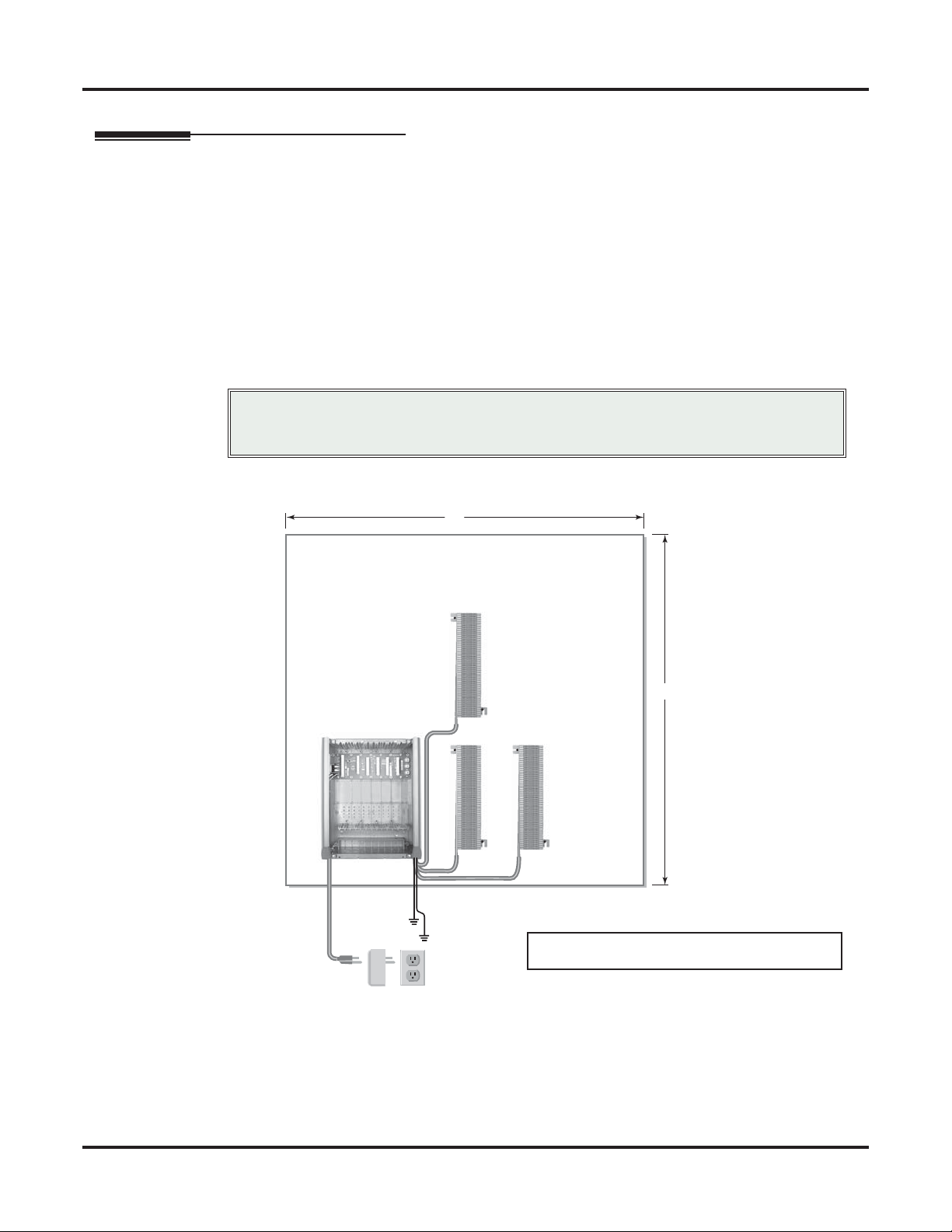
Before installing the common equipment, you should mount a Main Distribution Frame (MDF) plywood backboard in a centrally located spot. A 1/2 sheet of plywood (4’ x 4’) should be adequate for a DSX-80 4-Slot
KSU. A full sheet of plywood (8’ x 4’) should be adequate for a DSX160 cabinet. Be sure to mount the backboard using suitable fasteners, taking care to adhere to standard installation practices and local codes. See
ure 1: Installation Layout, DSX-80
The Main Equipment Cabinet requires a three-prong, dedicated 110 VAC 60 Hz circuit (NEMA 5-15 receptacle). The AC receptacle must be within 7 feet of the cabinet’s lower left corner.
Normally, you install the extension and line blocks to the right of the cabinet. Telco should also install the
RJ21X to the right of the cabinet
below and
Figure 2: Installation Layout, DSX-160 (page 23)
Fig-
for more.
Local codes may prohibit you from installing extensions,
Important
trunks and optional equipment in the same blocks.
.
Plywood backboard
4'
1093096 - 14
Line
Block
4'
Station
Block
Station
Block
To telco
ground
Surge
Protector
To earth
ground
Dedicated
AC Outlet
Note: The system will respond to telco ring signal in the
range of 40-130 VAC @ 20 Hz.
Figure 1: Installation Layout, DSX-80
22 ◆ Installation DSX-80/160 Hardware Manual
Page 29

Installing the Main Equipment Cabinet
15
Line
Blocks
Note: The system will respond to telco ring signal in the
range of 40-130 VAC @ 20 Hz.
Installation
Dedicated
AC Outlet
Surge
Protector
Removing the Cover
Before wall-mounting, remove the cover on the Main Equipment Cabinet.
To remove the cover:
1. Unscrew the two captive screws on the front of the cabinet cover.
2. Lift up slightly on the front of the cover — then gently slide the cover back to remove it.
Station
Blocks
To telco
ground
To earth
ground
Figure 2: Installation Layout, DSX-160
Station
Blocks
80000 - 12
DSX-80 4-Slot KSU Shown
Figure 3: Removing the Cover
DSX-80/160 Hardware Manual Installation ◆ 23
Page 30

Installing the Main Equipment Cabinet
Unpacking the Wall Mount Bracket
The wall mount bracket and screws are taped to the packing material in the Main Equipment Cabinet box.
Unpack the wall mount bracket and mounting screws.
80000 - 11
Figure 4: Wall Mount Bracket
Mounting the Wall Mount Bracket
Mount the wall mount bracket on the MDF in a convenient location, about 12” higher than where you want
the bottom of the cabinet to line up.
Figure 5: Mounting the Wall Mount Bracket
80000 - 14
24 ◆ Installation DSX-80/160 Hardware Manual
Page 31

Hanging the Cabinet
To hang the cabinet:
1. Hang the Main Equipment Cabinet on the wall mount hanger(s) as shown:
- See Figure 6: Hanging the DSX-80 4-Slot KSU below when hanging a DSX-80 4-Slot KSU.
- See Figure 7: Hanging the DSX-160 8-Slot KSU below when hanging an DSX-160 slot cabinet.
2. Using the remaining screws packed with the hanger, secure the cabinet to the plywood backboard.
Installing the Main Equipment Cabinet
Installation
Figure 6: Hanging the DSX-80 4-Slot KSU
80000 - 60
Two hangers are provided
with the DSX-160 KSU.
Figure 7: Hanging the DSX-160 8-Slot KSU
DSX-80/160 Hardware Manual Installation ◆ 25
Page 32
Grounding the Cabinet
Grounding the Cabinet
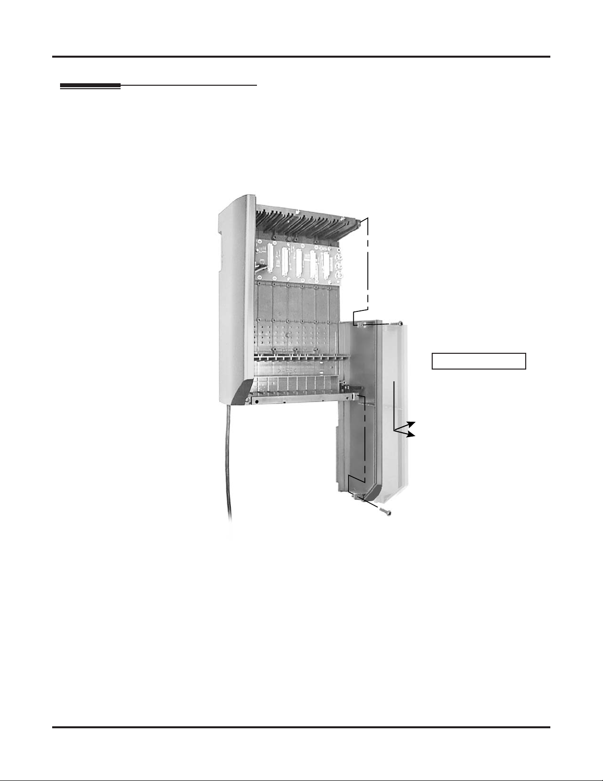
Removing the Right Side Panel
Remove the cabinet right side panel to gain easy access to the ground lugs and system cabling. The cabinet
has two ground connections: ETH (Earth Ground) and PBXG (PBX Ground).
To remove the right side panel:
1. Remove the two screws that secure the right side panel to the cabinet.
2. Carefully slide the right side panel down until it swings clear of the cabinet.
80000 - 16
Figure 8: Removing the Right Side Panel
DSX-80 4-Slot KSU Shown
26 ◆ Installation DSX-80/160 Hardware Manual
Page 33

Attaching the Ground Wire
You must connect your system to a known earth ground.
There are three ground terminations on the KSU: signal, earth, and PBX. You must connect all three termi-
nations to a known good earth ground using 12 AWG stranded copper wire.
Grounding the Cabinet
Important
To attach the ground wires:
1. Remove the lugs on the earth and PBX ground terminations.
2. Crimp ring terminals as required onto two 12 AWG stranded copper ground wires.
3. Install the ring terminals onto the earth and PBX ground terminations and firmly tighten.
4. Connect the other end of the ground wires to a known good earth ground.
Important
Do not plug in the power cord or reinstall the right side panel
until all card installation and cabling are complete.
Signal Ground
Earth Ground
PBX Ground
1093096 - 46
Installation
DSX-80 4-Slot KSU Shown
To known good
earth ground.
Figure 9: Attaching the Ground Wires
DSX-80/160 Hardware Manual Installation ◆ 27
Page 34

Grounding the Cabinet
Installing the RFI Suppressor Assembly
You must install an RFI Suppressor Assembly for the CPU audio and ethernet cables. The suppressor must
be mounted inside the cabinet and as close the CPU Card as possible.
Figure 10: Installing the RFI Suppressor Assembly
28 ◆ Installation DSX-80/160 Hardware Manual
Page 35

Installing the Power Supply
Power Supply Installation
The power supply provides the DC power sources required to operate the system.
To install a power supply:
1. Slide the power supply into the CN101 slot.
2. Using a long-shaft phillips head screwdriver, tighten the two screws that secure the power supply.
A DSX-160 may require up to 3 power supplies (depending on system configuration), using slots CN101,
CN102 and CN103. Refer to System Preparation (page 21) for more.
When installing multiple power supplies in DSX-160:
1. Install the first supply in slot CN101.
2. Install the second supply in slot CN103.
3. Install the third supply in slot CN102.
Installing the Power Supply
Installation
1093096 - 12
DSX-80 4-Slot KSU Shown
Figure 11: Installing the Power Supply
In case of fire, disconnect the power cord from the AC outlet.
Important
DSX-80/160 Hardware Manual Installation ◆ 29
Page 36

Installing Cards
Installing Cards
On-Premises Extensions
Install station equipment connected to ESIU and SLIU Cards as on-premises extensions only.
Hot Insertion of Cards
• Do not plug in the CPU Card hot (i.e., with the system power applied).
• You can plug in SLIU and COIU Cards hot as required.
• You can plug in ESIU Cards hot provided you first disconnect the station cabling from the card.
Installing the CPU
The CPU Card installs in the CN0 slot in the Main Equipment Cabinet.
To install the CPU Card:
1. Insert the battery (Sony CR2032 or NEC P/N EX0254-0040) into the battery clips.
2. Plug the CPU into slot CN0.
• Refer to Installing Optional Equipment (page 57) when connecting the audio inputs and outputs to the
CPU Card.
Important
Caution
Battery
1093096 - 3
Figure 12: Installing the CPU
30 ◆ Installation DSX-80/160 Hardware Manual
DSX-80 4-Slot KSU Shown
Page 37

Installing the 16ESIU Digital Station Cards
The 16ESIU provides the connection for 16 digital telephones. It also provides connection for DSS Consoles
(four max per system).
To install 16ESIU Cards:
1. Plug the 16ESIU Card for extensions 300-315 into slot CN1.
2.
Plug in additional ESIU Cards as required. See
3. Set the mode switch on each installed 16ESIU Card to RUN.
System Preparation (page 21)
Installing Cards
for more.
Installation
• In DSX-80, you cannot install more than two 16ESIU Cards.
Important
• In DSX-160, you cannot install more than two 16ESIU Cards per power supply.
1093096 - 16
DSX-80 4-Slot KSU Shown
Figure 13: Installing the 16ESIU Digital Station Card
DSX-80/160 Hardware Manual Installation ◆ 31
Page 38

Installing Cards
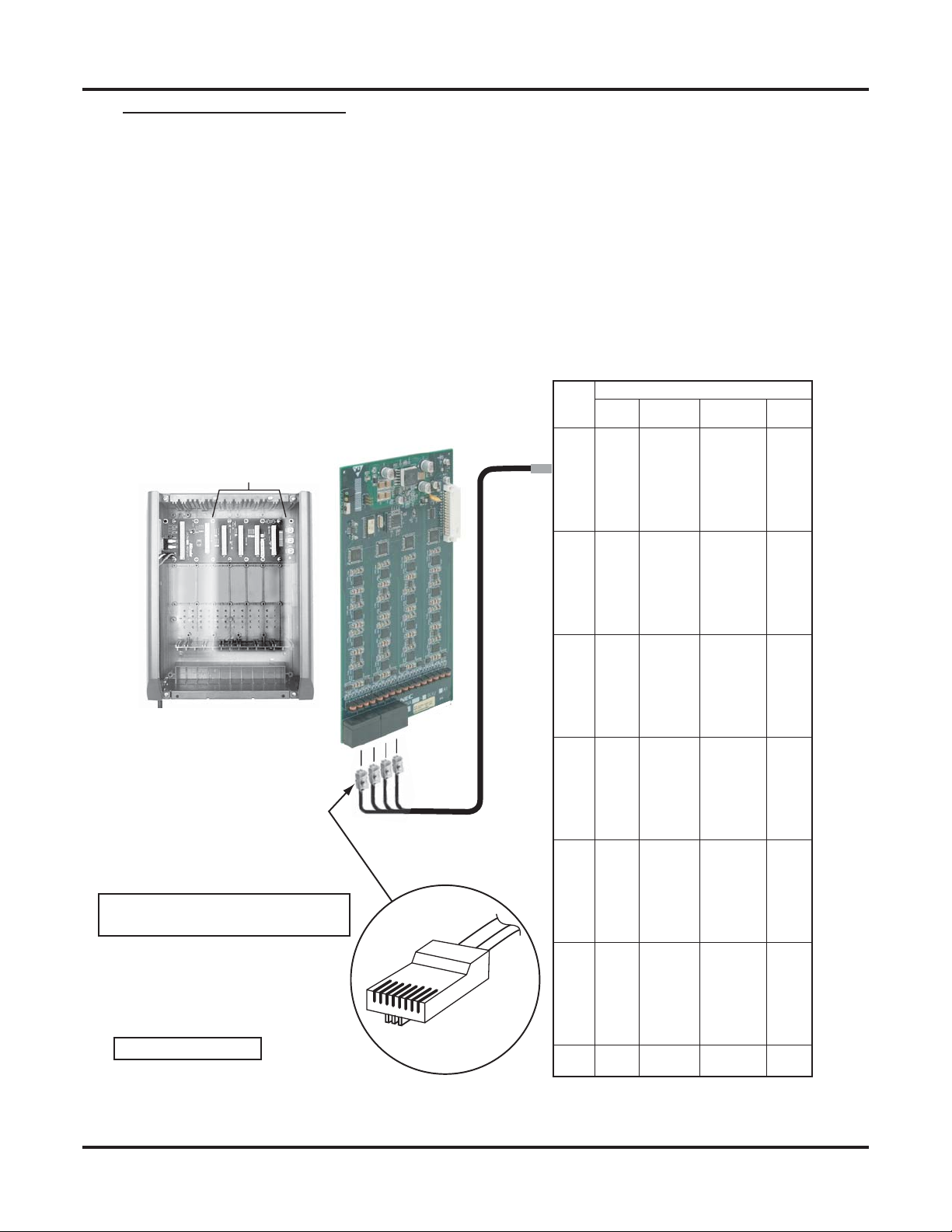
Connecting 16ESIU Cards
The 16ESIU Card, just like the COI and SLI Cards, uses 8-pin mod jacks to connect extensions. Using the
Installation Cable (P/N 808920) makes it easy to connect the cards to standard 66M1-50 connecting blocks.
These cables have six 8-pin modular jacks on one end and are unterminated on the other. Each jack connects
four extensions. At minimum, the installation site needs:
❥ One 66M1-50 block and Installation Cable (P/N 808920) for extensions and optional equipment.
❥ One 66M1-50 block and Installation Cable (P/N 808920) for analog lines.
❥ Depending on your card configuration and local codes, you may need an additional 66M1-50 block and
Installation Cable (P/N 808920) for optional equipment.
To punch down the cables:
1. For each 66M1-50 block, punch down the Installation Cable in standard color-code order.
PCB Location
4 Slot Cabinet
shown
To make your own cables, see Making
Your Own Cables (page 39).
DSX-80 4-Slot KSU Shown
16ESIU PCB
4
3
2
1
8
1
RJ61X Plug
Extensions 300-323 Shown
25-PAIR CABLE
1
2
3
4
5
6
1093096 - 18
BLOCK
TERM
10
11
12
13
14
15
16
17
18
19
20
21
22
23
24
25
26
27
28
29
30
31
32
33
34
35
36
37
38
39
40
41
42
43
44
45
46
47
48
49
50
1
2
3
4
5
6
7
8
9
COLOR
CODE
WHT-BLU
BLU-WHT
WHT-ORN
ORN-WHT
WHT-GRN
GRN-WHT
WHT-BRN
BRN-WHT
WHT-SLT
SLT-WHT
RED-BLU
BLU-RED
RED-ORN
ORN-RED
RED-GRN
GRN-RED
RED-BRN
BRN-RED
RED-SLT
SLT-RED
BLK-BLU
BLU-BLK
BLK-ORN
ORN-BLK
BLK-GRN
GRN-BLK
BLK-BRN
BRN-BLK
BLK-SLT
SLT-BLK
YEL-BLU
BLU-YEL
YEL-ORN
ORN-YEL
YEL-GRN
GRN-YEL
YEL-BRN
BRN-YEL
YEL-SLT
SLT-YEL
VIO-BLU
BLU-VIO
VIO-ORN
ORN-VIO
VIO-GRN
GRN-VIO
VIO-BRN
BRN-VIO
VIO-SLT
SLT-VIO
FUNCTION RJ61XRJ61X
300 T
300 R
301 T
301 R
302 T
302 R
303 T
303 R
304 T
304 R
305 T
305 R
306 T
306 R
307 T
307 R
308 T
308 R
309 T
309 R
310 T
310 R
311 T
311 R
312 T
312 R
313 T
313 R
314 T
314 R
315 T
315 R
316 T
316 R
317 T
317 R
318 T
318 R
319 T
319 R
320 T
320 R
321 T
321 R
322 T
322 R
323 T
323 R
NC
NC
5
4
3
6
2
7
1
8
5
4
3
6
2
7
1
8
5
4
3
6
2
7
1
8
5
4
3
6
2
7
1
8
5
4
3
6
2
7
1
8
5
4
3
6
2
7
1
8
Figure 14: Connecting 16ESIU Digital Station Cards
32 ◆ Installation DSX-80/160 Hardware Manual
Page 39

Installing 16SLIU and 8SLIU Analog Station Cards
The 16SLIU connects 16 analog telephones. The 8SLIU connects for 8 analog telephones.
To install a SLIU Card:
1. Turn to System Preparation (page 21) to be sure you haven’t exceeded the allowable system load factor.
2. Plug a SLIU Card into any available slot from CN2-CN8.
- You should reserve CN1 for a 16ESIU Card.
3. Set the mode switch on each installed SLIU Card to RUN
Installing Cards
Installation
1093096 - 43
DSX-80 4-Slot KSU Shown
Figure 15: Installing a 16SLIU or 8SLIU Analog Station Card
DSX-80/160 Hardware Manual Installation ◆ 33
Page 40
Installing Cards
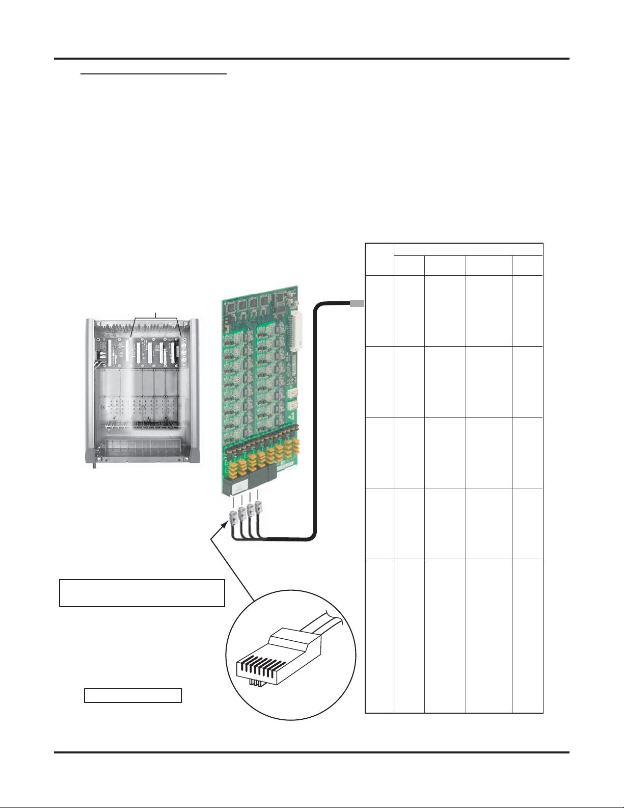
Connecting 16SLIU and 8SLIU Cards
The SLIU Card, just like the COI and16ESIU Cards, uses 8-pin mod jacks to connect extensions. Using the
Installation Cable (P/N 808920) makes it easy to connect the cards to standard 66M1-50 connecting blocks.
These cables have six 8-pin modular jacks on one end and are unterminated on the other. Each jack connects
four extensions. At minimum, the installation site needs:
❥ One 66M1-50 block and Installation Cable (P/N 808920) for extensions and optional equipment.
❥ One 66M1-50 block and Installation Cable (P/N 808920) for analog lines.
❥ Depending on your card configuration and local codes, you may need an additional 66M1-50 block and
Installation Cable (P/N 808920) for optional equipment.
To punch down the cables:
For each 66M1-50 block, punch down the Installation Cable in standard color-code order.
PCB Location
4 Slot Cabinet
shown
To make your own cables, see Making
Your Own Cables (page 39).
DSX-80 4-Slot KSU Shown
16SLIU PCB
4
3
2
1
8
1
RJ61X Plug
Extensions 316-331 Shown
25-PAIR CABLE
1
2
3
4
5
6
1093096 - 38
BLOCK
TERM
1
2
3
4
5
6
7
8
9
10
11
12
13
14
15
16
17
18
19
20
21
22
23
24
25
26
27
28
29
30
31
32
33
34
35
36
37
38
39
40
41
42
43
44
45
46
47
48
49
50
COLOR
CODE
WHT-BLU
BLU-WHT
WHT-ORN
ORN-WHT
WHT-GRN
GRN-WHT
WHT-BRN
BRN-WHT
WHT-SLT
SLT-WHT
RED-BLU
BLU-RED
RED-ORN
ORN-RED
RED-GRN
GRN-RED
RED-BRN
BRN-RED
RED-SLT
SLT-RED
BLK-BLU
BLU-BLK
BLK-ORN
ORN-BLK
BLK-GRN
GRN-BLK
BLK-BRN
BRN-BLK
BLK-SLT
SLT-BLK
YEL-BLU
BLU-YEL
YEL-ORN
ORN-YEL
YEL-GRN
GRN-YEL
YEL-BRN
BRN-YEL
YEL-SLT
SLT-YEL
VIO-BLU
BLU-VIO
VIO-ORN
ORN-VIO
VIO-GRN
GRN-VIO
VIO-BRN
BRN-VIO
VIO-SLT
SLT-VIO
FUNCTION RJ61XRJ61X
316 T
316 R
317 T
317 R
318 T
318 R
319 T
319 R
320 T
320 R
321 T
321 R
322 T
322 R
323 T
323 R
324 T
324 R
325 T
325 R
326 T
326 R
327 T
327 R
328 T
328 R
329 T
329 R
330 T
330 R
331 T
331 R
NC
NC
5
4
3
6
2
7
1
8
5
4
3
6
2
7
1
8
5
4
3
6
2
7
1
8
5
4
3
6
2
7
1
8
5
4
3
6
2
7
1
8
5
4
3
6
2
7
1
8
Figure 16: Connecting 16SLIU and 8SLIU Cards
34 ◆ Installation DSX-80/160 Hardware Manual
Page 41

Installing 16COIU and 8COIU Analog Line Cards
The 16COIU connects 16 analog loop start lines. The 8SCOIU connects 8 analog loop start lines.
To install a COIU Card:
1. Turn to System Preparation (page 21) to be sure you haven’t exceeded the allowable system load factor.
2. Plug a COIU Card into any available slot from CN2-CN8.
- You should reserve CN1 for a 16ESIU Card.
3. Set the mode switch on each installed COIU Card to Run.
Installing Cards
Installation
1093096 - 17
Notes:
• The system will respond to telco ring signal in
the range of 42-103 VAC @ 20 Hz.
• Telco battery must be 44-56 VDC.
DSX-80 4-Slot KSU Shown
Figure 17: Installing a 16COIU or 8COIU Analog Line Card
DSX-80/160 Hardware Manual Installation ◆ 35
Page 42
Installing Cards
Connecting 16COIU and 8COIU Cards
The COIU Card, just like the SLI and16ESIU Cards, uses 8-pin mod jacks to connect extensions. Using the
Installation Cable (P/N 808920) makes it easy to connect the cards to standard 66M1-50 connecting blocks.
These cables have six 8-pin modular jacks on one end and are unterminated on the other. Each jack connects
four lines. At minimum, the installation site needs:
❥ One 66M1-50 block and Installation Cable (P/N 808920) for extensions and optional equipment.
❥ One 66M1-50 block and Installation Cable (P/N 808920) for analog lines.
❥ Depending on your card configuration and local codes, you may need an additional 66M1-50 block and
Installation Cable (P/N 808920) for optional equipment.
To punch down the cables:
For each 66M1-50 block, punch down the Installation Cable in standard color-code order.
PCB Location
4 Slot Cabinet
shown
To make your own cables, see Making
Your Own Cables (page 39).
DSX-80 4-Slot KSU Shown
Figure 18: Connecting 16COIU and 8COIU Cards
16COIU PCB
4
3
2
1
8
1
RJ61X Plug
1
2
3
4
NC
1093096 - 19
BLOCK
TERM
1
2
3
4
5
6
7
8
9
10
11
12
13
14
15
16
17
18
19
20
21
22
23
24
25
26
27
28
29
30
31
32
33
34
35
36
37
38
39
40
41
42
43
44
45
46
47
48
49
50
Lines 1-16
25-PAIR CABLE
COLOR
CODE
WHT-BLU
BLU-WHT
WHT-ORN
ORN-WHT
WHT-GRN
GRN-WHT
WHT-BRN
BRN-WHT
WHT-SLT
SLT-WHT
RED-BLU
BLU-RED
RED-ORN
ORN-RED
RED-GRN
GRN-RED
RED-BRN
BRN-RED
RED-SLT
SLT-RED
BLK-BLU
BLU-BLK
BLK-ORN
ORN-BLK
BLK-GRN
GRN-BLK
BLK-BRN
BRN-BLK
BLK-SLT
SLT-BLK
YEL-BLU
BLU-YEL
YEL-ORN
ORN-YEL
YEL-GRN
GRN-YEL
YEL-BRN
BRN-YEL
YEL-SLT
SLT-YEL
VIO-BLU
BLU-VIO
VIO-ORN
ORN-VIO
VIO-GRN
GRN-VIO
VIO-BRN
BRN-VIO
VIO-SLT
SLT-VIO
FUNCTION RJ61XRJ61X
1 T
1 R
2 T
2 R
3 T
3 R
4 T
4 R
5 T
5 R
6 T
6 R
7 T
7 R
8 T
8 R
9 T
9 R
10 T
10 R
11 T
11 R
12 T
12 R
13 T
13 R
14 T
14 R
15 T
15 R
16 T
16 R
5
4
3
6
2
7
1
8
5
4
3
6
2
7
1
8
5
4
3
6
2
7
1
8
5
4
3
6
2
7
1
8
5
4
3
6
2
7
1
8
5
4
3
6
2
7
1
8
36 ◆ Installation DSX-80/160 Hardware Manual
Page 43

Installing T1/E1/PRI Cards
Normally you connect the T1/E1/PRI Card to a separately-purchased Channel Service Unit (CSU). Use a
standard straight-through CAT 5 cable to connect the T1/E1/PRI Card to the CSU. The CSU in turn connects
to the telco smart jack.
❥ The T1/E1/PRI Card also provides 32E1 support. E1 is not used in North America.
❥ You can install a T1/E1/PRI Card in any slot except slot 1.
❥ A commercially available T1 Tester is recommended.
Mode switch
Installing Cards
Installation
80061 - 2
RX1 T
RX1 R
TX1 T
TX1 R
CN7 and CN9 jumpers are not
required for T1 installations.
CN9
E1
T1
CN9
E1
T1
CN7
CN7
Connector
1 2 3 4 5 6 7 8
RJ48C Connector
Pinouts
T1 Grounding Requirements
Be sure to run a 12 AWG
jumper wire from the SG (Signal Ground) lug to the ETH
(Earth Ground) lug.
RS232 Port
RJ48C
Telco
Smart Jack
Straight-Through
CAT 5 Cable
Figure 19: Setting Up the T1/E1/PRI Card
DSX-80/160 Hardware Manual Installation ◆ 37
Page 44

Installing Cards
Connecting the T1/E1/PRI Card
To install the T1/E1/PRI Card:
1. Turn to System Preparation (page 21) to be sure you haven’t exceeded the allowable system load factor.
2. Set jumpers CN7 and CN9 to the T1 position.
- CN7 and CN9 are not required for T1 installations. You can optionally leave them off.
3. Plug in T1/E1/PRI Trunk Cards as required.
4. Set the mode switch on each T1/E1/PRI Card to RUN.
5.
Using a standard straight-through CAT 5 cable, connect the T1/E1/PRI Card RJ48C connector to your CSU.
80000 - 76
DSX-80 4-Slot KSU Shown
Figure 20: Connecting the T1/E1/PRI Card
38 ◆ Installation DSX-80/160 Hardware Manual
Page 45
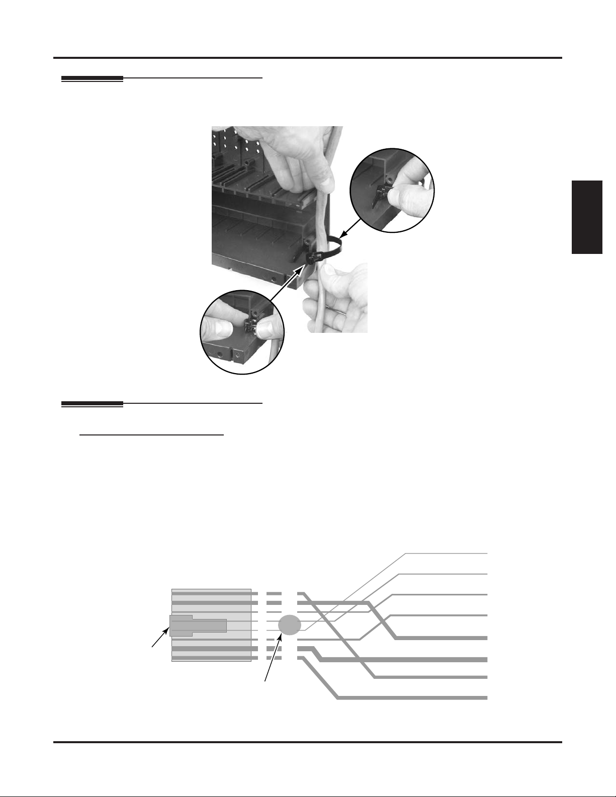
Securing the Cables
8
After you have punched down your cables, route them through the side of the cabinet and secure them with
the strain relief.
Installing Cards
0000 - 33
Installation
Figure 21: Securing the Cables
Making Your Own Cables
Making Your Own Installation Cables
The following products should help if you make your own cables. The connector is generally referred to
as a RJ45 connector wired in an RJ61X configuration. Check with your local supplier for other compa-
rable products.
❥ Suttle SE-266-8K 8 Position Modular Plug (requires an SE-166 or SE-166-6 modular crimping tool).
❥ Hubbell BRFT4P Snap-On 8 Position Modular Plug (does not require a special crimping tool).
To CPU
Mod Jack
Latch
faces up
80000 - 18C
RJ61X
Pin
1
2
3
4
5
6
7
8
Note
reversal
Port
Designation
4T
3T
2T
1R
1T
2R
3R
4R
To 66 Block
WHT-BLU (1T)
BLU-WHT (1R)
WHT-ORN (2T)
ORN-WHT (2R)
WHT-GRN (3T)
GRN-WHT (3R)
WHT-BRN (4T)
BRN-WHT (4R)
Figure 22: 8-Pin (RJ61X) Jack Pinouts
DSX-80/160 Hardware Manual Installation ◆ 39
Page 46
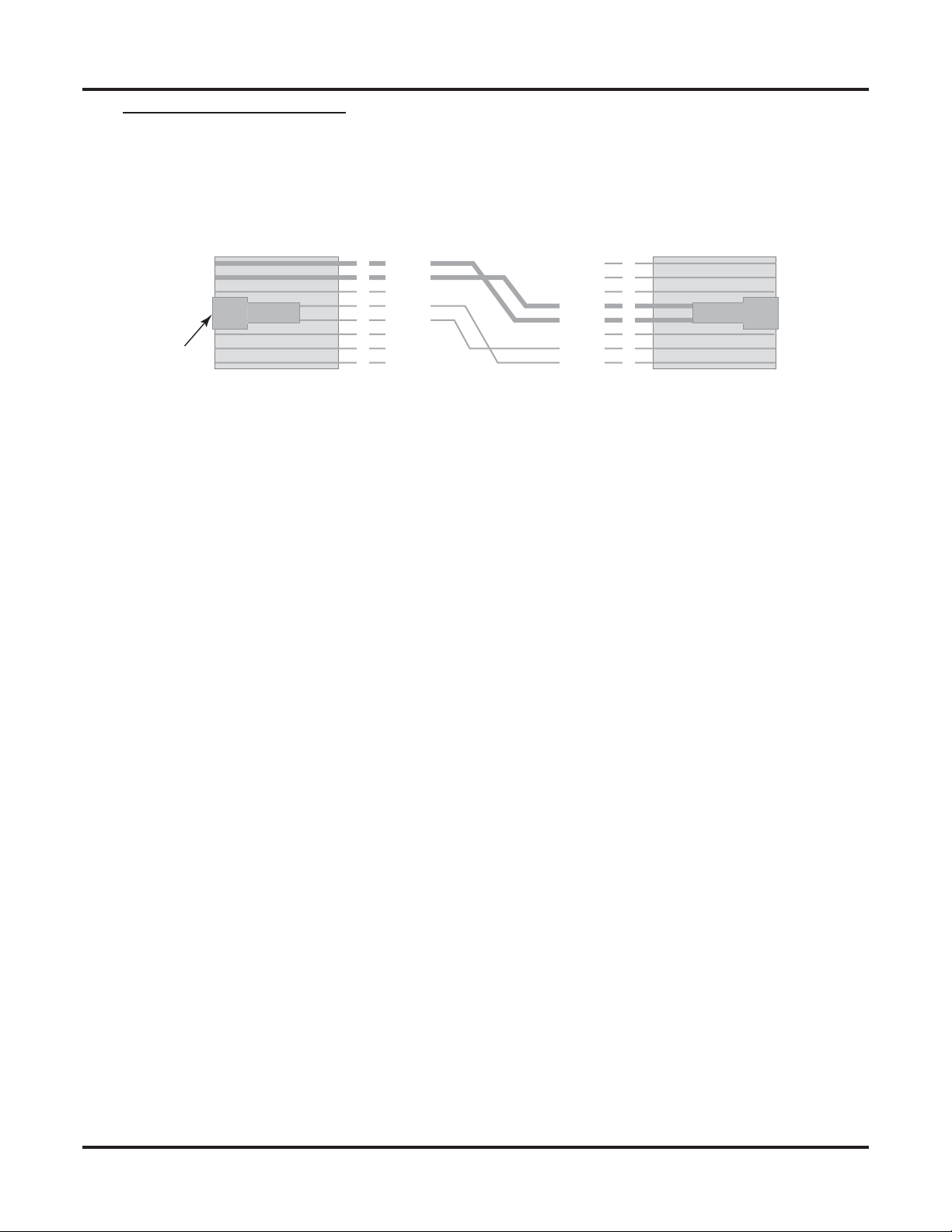
Installing Cards
Making a T1/E1/PRI Crossover Cable
If you don’t have a T1 Tester, you can alternately test Tie Line operation between two T1/E1/PRI Cards in
the same cabinet or facility using the cable shown below. Using this same setup, you can loop a Tie Line to a
DID Line to test your DID routing before connecting to the CSU.
To T1 PCB To T1 PCB
Latch
faces up
80061 - 3
Pin
1
2
3
4
5
6
7
8
RX1T
RX1R
TX1T
TX1R
TX1R
TX1T
RX1R
RX1T
Pin
8
7
6
5
4
3
2
1
Connecting Two T1 PCBs Together without a Telco T1 Circuit
(For Tie Line Testing)
Figure 23: Making a T1/E1/PRI Crossover Cable
40 ◆ Installation DSX-80/160 Hardware Manual
Page 47
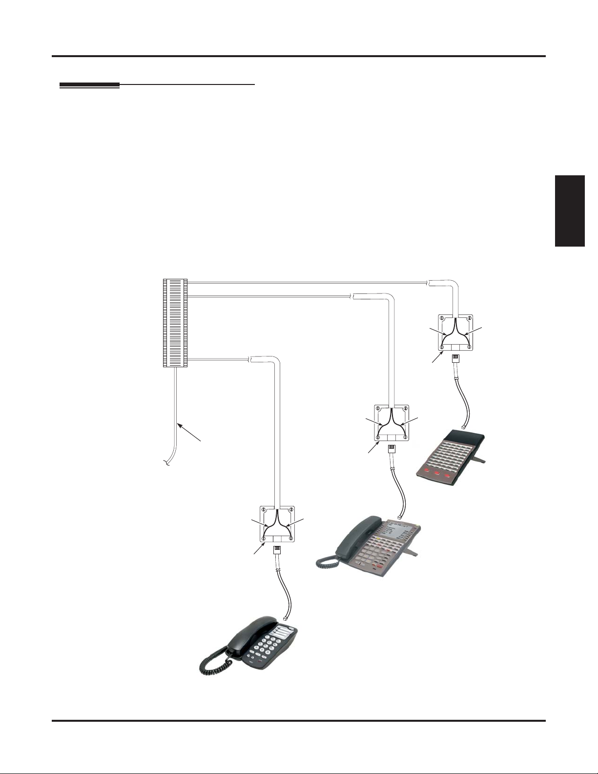
Connecting Extensions and Setting Up the Telephone
Connecting Extensions
Each 16ESIU Card connects 16 digital extensions. Each 16SLIU Card connects 16 analog extensions, and
each 8SLIU Card connects 8 analog extensions.
To connect extensions:
1. Using Figure 14: Connecting 16ESIU Digital Station Cards (page 32) and Figure 16: Connecting
16SLIU and 8SLIU Cards (page 34) as a guide, plug the installation cable mod jacks into the appropriate
connectors on the station cards.
2. Install a modular jack for each extension within 6 feet of the telephone’s location.
3. For each extension, run one-pair 24 AWG station cable from the station block to the modular jack.
- To make adds, moves, and changes easier, be sure to leave a service loop in your station cable.
4.
Terminate the station cable
5. Install bridging clips as required.
Connecting Extensions and Setting Up the Telephone
WHT/BLU
ESIU
-
BLU/WHT
leads to the
RED
and
GRN
lugs in the modular jack.
Installation
1093096 - 20
Station
Block
ESIU
SLIU
25-Pair
Installation Cable
(P/N 80892)
YEL
BLU-WHT
RED
625
Modular
Jack
BLK
WHT-BLU
GRN
YEL
BLU-WHT
RED
625
Modular
Jack
DSX Keyset
YEL
BLU-WHT
RED
625
Modular
Jack
BLK
WHT-BLU
GRN
DSS Console
BLK
WHT-BLU
GRN
DTH-1-1
Figure 24: Connecting Extensions
DSX-80/160 Hardware Manual Installation ◆ 41
Page 48
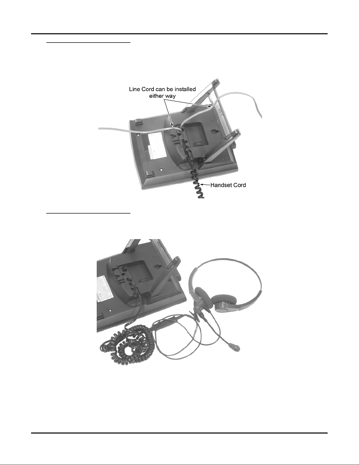
Connecting Extensions and Setting Up the Telephone
Installing the DSX Keyset Handset and Line Cord.
When installing the handset, plug the handset cord into the handset jack on the bottom of the telephone. The
handset cord routes through the lower channel on the right side of the telephone base. The line cord does not
use a channel and drapes down from the telephone line cord jack or connects to the telephone legs.
Figure 25: Installing the Handset and Line Cord
Installing the DSX Keyset Optional Headset
When installing an optional headset, plug the headset cord in the headset jack on the bottom of the telephone. The headset cord routes through the upper channel on the right side of the telephone base.
Figure 26: Installing the Optional Headset
42 ◆ Installation DSX-80/160 Hardware Manual
Page 49

Connecting Extensions and Setting Up the Telephone
Installing the DSS Console Line Cord
The DSS Console connects to an available port on an 16ESIU Card, just like a keyset. You can install four
maximum per system. The DSS Console line cord does not use a channel and drapes down from the telephone line cord jack or connects to the telephone legs.
Line Cord can be installed
either way
Installation
1093096 - 23
Figure 27: Installing the DSS Console Line Cord
DSX-80/160 Hardware Manual Installation ◆ 43
Page 50

Connecting Extensions and Setting Up the Telephone
Keyset and DSS Console Two Position Angle Adjustment
To set the low viewing angle position:
1. Fold the legs all the way back.
10 930 96 - 34
1
Figure 28: Setting the Low Viewing Angle
To set the high viewing angle position:
1. Flip up the two leg supports.
2. Fold the legs back until the leg supports contact the base.
2
109 309 6 - 3 5
1
Figure 29: Setting the High Viewing Angle
44 ◆ Installation DSX-80/160 Hardware Manual
Page 51

Connecting Extensions and Setting Up the Telephone
Removing the Faceplate
You’ll need to remove the telephone faceplate to write on the label or install a DESI custom label.
To remove the faceplate:
1. Put your finger in the recessed area under the faceplate and lift off the faceplate.
1093096 - 36
Installation
Figure 30: Removing the Telephone Faceplate
DSX-80/160 Hardware Manual Installation ◆ 45
Page 52
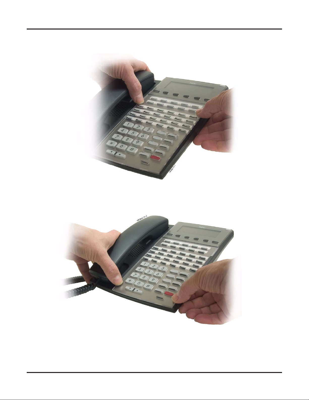
Connecting Extensions and Setting Up the Telephone
To reinstall the faceplate:
1. Snap back into place as shown.
Figure 31: Reinstalling the Telephone Faceplate
46 ◆ Installation DSX-80/160 Hardware Manual
Page 53

Connecting Lines
Connecting Analog Lines
Each 16COIU Card connects 16 loop start CO trunks. Each 8COIU Card connects 8 loop start CO trunks.
To connect analog trunks:
1. Using Figure 18: Connecting 16COIU and 8COIU Cards (page 36) as a guide, plug the installation cable
mod jacks into the appropriate connectors on the COIU Cards.
2. For each line, run one pair cross-connect wire between the line block and the CPE (customer side) of the
telco’s RJ21X.
3. Install bridging clips as required.
Connecting Lines
Installation
One-Pair
Cross Connect
1093096 - 21
Line
Block
Connecting T1 Lines
Turn to Installing T1/E1/PRI Cards (page 37).
Telco
RJ21X
25-Pair Cable
to Central Office
25-Pair
Installation Cable
(P/N 80892)
Figure 32: Installing Analog Lines
DSX-80/160 Hardware Manual Installation ◆ 47
Page 54

Powering Up the System
Powering Up the System
Before Powering Up
The system’s built-in Automatic Slot Configuration automatically sets up station and line cards when you
initially power up the system. On power up, the system scans the cards from left to right and sets up the station and line numbering as follows:
❥ Extension numbers will begin with 300 in the first slot and increment from left to right.
❥ Line numbers will begin with 101 (starting from the first installed COIU or T1/E1/PRI Card) and will
also increment from left to right.
❥ For example, in a 16x32, the numbering will be:
1st 16ESIU Card = Extensions 300-315.
2nd 16ESIU Card = Extensions 316-331.
16COIU Card = Lines 101-116.
❥ In addition,
To power up the system:
- You do not need to reattach the right side panel before powering up the system. Leaving the right
1. Make sure the system is properly grounded and the card bracket is reinstalled and secured.
2. Install a surge protector in the AC outlet you intend to use for system power.
3. Plug the main cabinet’s AC power cord into its surge protector.
4. Turn on the main cabinet power switch. After about 30 seconds, verify the system LEDs.
the system will also automatically set up a station or line card when you plug it in hot.
side panel removed makes the station and line cabling more accessible.
LED Normal Power-On Status
Power Supply • All three LEDs on (green)
CPU Card • Top LED winks on (blue)
ESIU, SLIU, and COIU Cards • Top LED flashing (slowly green)
• Bottom LED flashes (yellow) when ports
on the card are busy. The faster the flash,
the more ports are busy.
48 ◆ Installation DSX-80/160 Hardware Manual
Page 55
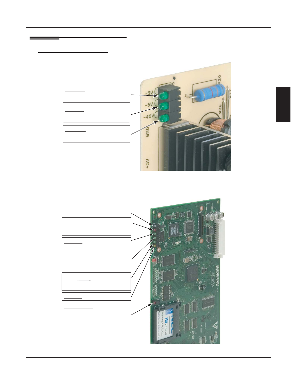
System LEDs
Power Supply LEDs
Powering Up the System
1093096 - 13
+ 5 V DC (Green)
On: +5 V DC power present.
Off: +5 V DC power not present.
- 5 V DC (Green)
On: -5 V DC power present.
Off: -5 V DC power not present.
- 40 V DC (Green)
On: -40 V DC power present.
Off: -40 V DC power not present.
CPU Card LEDs
CPU Running (blue)
Off: CPU is not functioning.
On: System is starting up.
Wink On: System is running.
Error (red)
Off: No errors present.
On: System has an error.
Installation
Figure 33: Power Supply LEDs
1093096 - 24
USB Port (green)
Off: USB port idle.
Flashing: Activity on the USB port.
Serial Port (green)
Off: Serial port idle.
Flashing: Activity on serial port.
Ethernet Port (green)
Off: Ethernet port idle.
Flashing: Activity on Ethernet port.
Not Used (yellow)
CompactFlash (red)
Off: CompactFlash card idle
or not installed.
On: System is accessing the
CompactFlash card.
Figure 34: CPU LEDs
DSX-80/160 Hardware Manual Installation ◆ 49
Page 56

Powering Up the System
Digital Station (ESIU), Analog Station (SLIU), and Analog Line (COIU) Card LEDs
Sync Status (green)
Fast Flash: PCB running, waiting
for sync. Same as having
the mode switch set to stop.
System has an error.
Slow Flash: PCB running, in sync.
Port Activity (yellow)
Off: All ports on PCB idle.
Flash: Ports are busy. The faster
the flash, the more ports
are busy.
10 930 96 - 25
Figure 35: Digital Station (ESIU), Analog Station (SLIU), and Analog Line (COIU) Card LEDs
50 ◆ Installation DSX-80/160 Hardware Manual
Page 57

T1/E1/PRI Card LEDs
Powering Up the System
Port Activity
(Yellow)
Off: All ports on PCB idle.
Flash: Port(s) busy. The faster the flash, the more
ports are busy.
Sync (Master) (Green)
Off: T1 PCB is in the slave mode (i.e., getting the
clock from the connected T1 circuit).
On: T1 PCB is
providing the master clock to the
telco and is in sync.
Flash:
Loop (Slave) (Green)
T1 PCB is providing the master clock but is
not in sync
.
Off: T1 PCB is in the master mode (i.e., providing
the clock to the connected T1 circuit).
On: T1 PCB is in sync with the external clock
Flash:
T1 PCB
is not in sync with the external clock
source (and is not
LOS (Loss of Signal) or Red Alarm (Red)
source (and is not
providing the master clock).
providing the master clock)
Off: Signal from the connected telco T1 Circuit is
present.
On: Signal from the connected telco T1 circuit is
not present.
An LOS alarm means there is a problem upstream
from the T1 PCB.
BPV (Bi-Polar Violation) Alarm (Red)
This alarm indicates that consecutive “one” pulses
have been received in the T1 signal in error.
Off: The telco’s T1 signal does not contain
Bi-Polar Violations.
On: The telco’s T1 signal is in error. It contains
Bi-Polar Violations.
A BPV alarm means there is a problem upstream from
the T1 PCB.
PCB Running (Green)
Slow flash: T1 PCB running.
On: T1 PCB starting.
Installation
.
AIS (Alarm Indication Signal) or Blue Alarm (Red)
The telco sends an AIS alarm signal to the T1 PCB if
the telco receives faulty data from another device on
its network (i.e., upstream). It sends the AIS alarm signal to the PCB instead of the faulty data it received.
Off: AIS signal not received
On: AIS received
from telco.
from telco.
An AIS alarm means there is a problem upstream
from the telco (and upstream from the T1 PCB).
Yellow (RAI or Remote Alarm Indication) Alarm (Red)
The telco sends an RAI alarm to the T1 PCB if it
detects a problem with the T1 signal received from the
installation site. The problem can come from the T1
PCB, the CSU (if any), or be caused by faulty cabling.
Off: RAI signal not received
On: RAI received
from telco.
from telco.
An RAI alarm means there is a problem downstream
from the telco (i.e., in the T1 PCB, CSU, or cabling).
T1 PCBCSUTelco
U
pstrea
m
from T1 PCB
D
ownstrea
m
from T1 PCB
Figure 36: T1/E1/PRI Card LEDs
DSX-80/160 Hardware Manual Installation ◆ 51
Page 58

Finishing the Installation
Finishing the Installation
Reinstalling the Side Panel
To reinstall the side panel:
1. Carefully realign the right side panel and slide it into position.
2. Reattach the two screws that secure the right side panel to the cabinet.
80000 - 16 A
DSX-80 4-Slot KSU Shown
Figure 37: Reinstalling the Side Panel
52 ◆ Installation DSX-80/160 Hardware Manual
Page 59

Reinstalling the Front Cover
To reinstall the front cover:
1. Hook the tabs on the rear of the cover into their associated slots.
2. Push the front of the cover into place.
3. Screw in the two captive screws that secure the cover to the cabinet.
Finishing the Installation
Installation
80000 - 12 A
Figure 38: Reinstalling the Front Cover
DSX-80/160 Hardware Manual Installation ◆ 53
Page 60
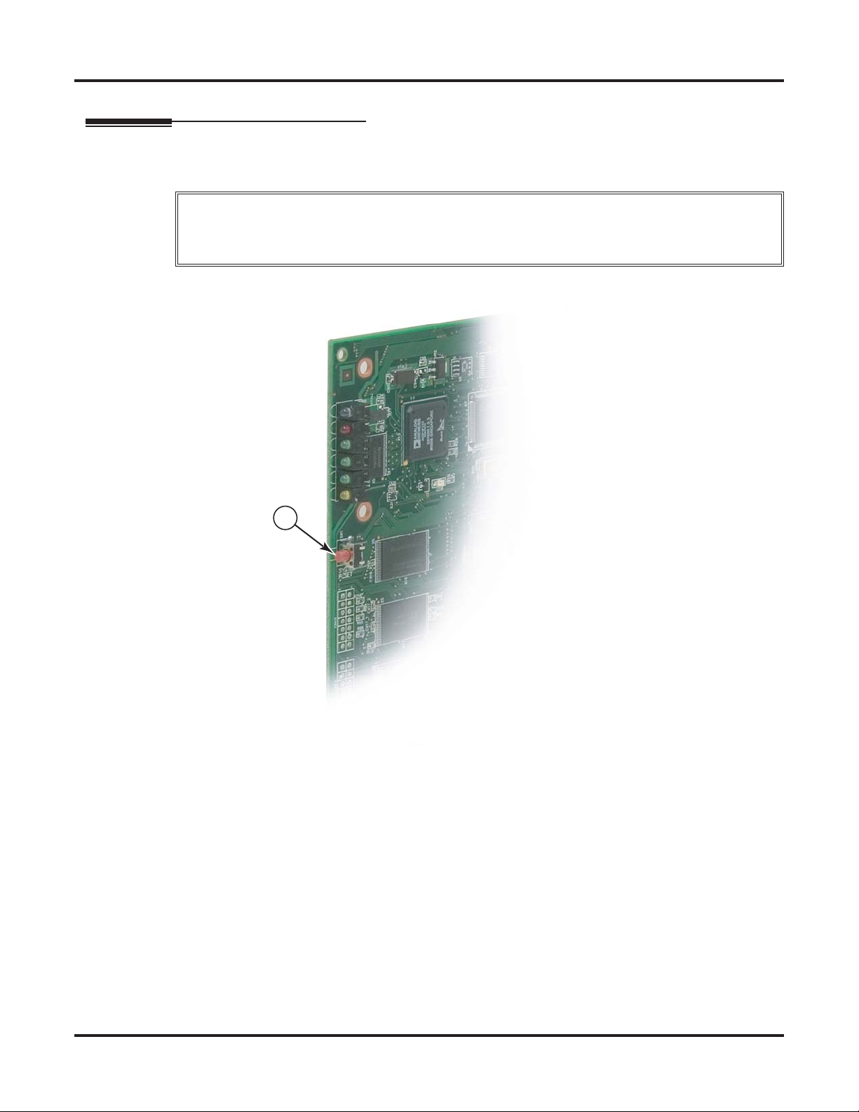
Resetting and Initializing the System
Resetting and Initializing the System
Resetting the System
To reset the system:
If the system’s RS-232 connection uses twisted pair cable, before resetting do one of the following:
Important
• Make sure the RS-232 cable is connected at both ends (i.e., PC and CPU).
• If the RS-232 cable is disconnected from the PC, be sure the cable is also disconnected from the CPU.
1. Briefly press (tap) the Reset Switch on the CPU.
1093096 - 41
1
Figure 39: Resetting the System
54 ◆ Installation DSX-80/160 Hardware Manual
Page 61
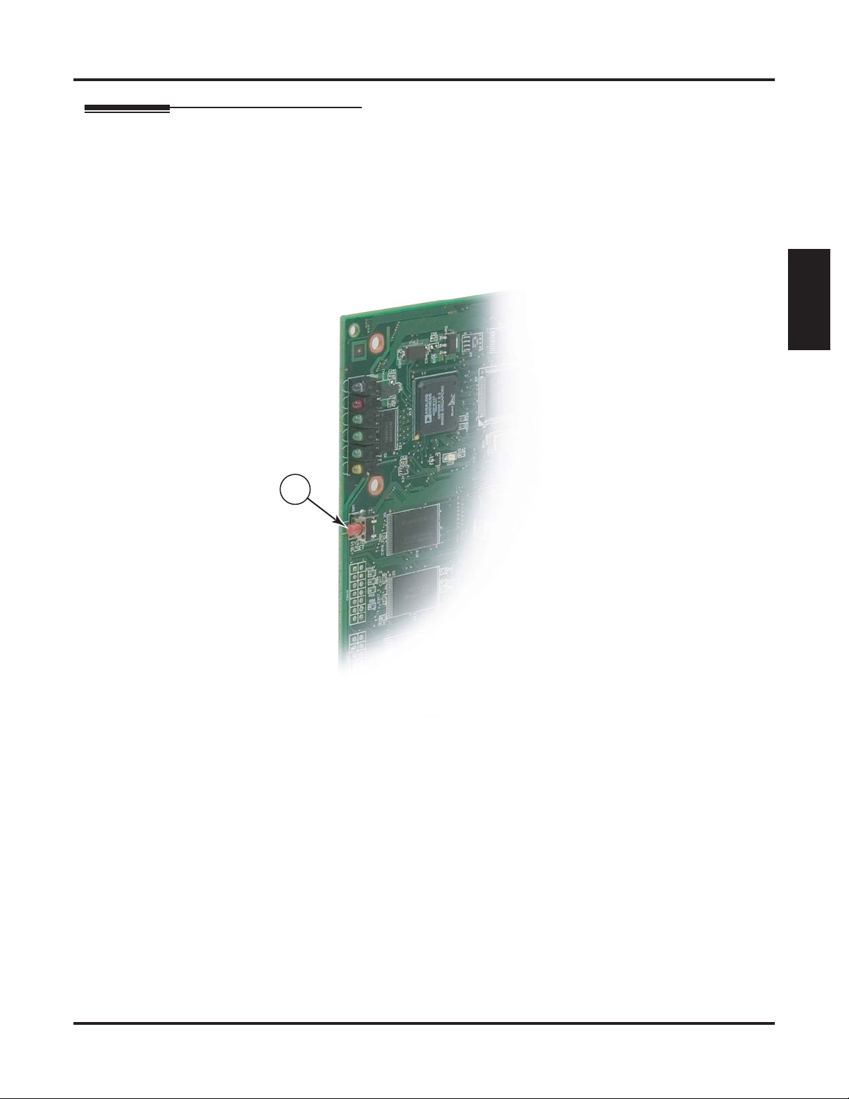
Initializing the System
To initialize (cold start) the system:
- This erases all your stored programming and returns the system to its default settings.
1. Turn off the system.
2. Press and hold the Reset Switch on the CPU while turning on the system power.
3. When all the LEDs on the CPU light and then go out, release the Reset Switch.
- The system will restart with the default settings.
Resetting and Initializing the System
Installation
1093096 - 42
2, 3
Figure 40: Initializing the System
DSX-80/160 Hardware Manual Installation ◆ 55
Page 62

Upgrading the System Software
Upgrading the System Software
Upgrade System Software
To upgrade system software from a CompactFlash card:
1. Remove the IntraMail CompactFlash card (if installed), then insert the CompactFlash card containing the
system software into the CPU.
- Although advisable, backing up the site programming is not required.
2. Press and hold the Reset Switch on the CPU.
3. When all the LEDs on the CPU light and then go out, release the Reset Switch.
- The new system software will automatically load. The system restarts after the load completes with
all the initial site programming intact.
4. Once the system restarts:
- Remove the software upgrade CompactFlash card.
- Insert the IntraMail CompactFlash card.
- Reset the system.
2
1
1093096 - 40
Figure 41: Loading System Software from a CompactFlash Card
56 ◆ Installation DSX-80/160 Hardware Manual
Page 63

Installing Optional
Equipment
Installing IntraMail
Installing IntraMail
Setting Up IntraMail for the First Time
■ A default system (with no voice mail installed) provides the Built-In Automated Attendant. See Automated Attendant,
Built-In in the IntraMail section of the System Guide for more.
■ If you have another (external) voice mail installed, you must disconnect and unprogram it before installing IntraMail.
To set up IntraMail:
1. Plug the IntraMail CompactFlash card into the CPU.
2. Reset the system. The IntraMail automatically installs.
- If updating from the Built-In Automated Attendant, just rerecord your Instruction Menu Messages.
Your Answer Schedule and Dial Action Table programing remain intact.
- By default, the first 16 (300-315) mailboxes are active/enabled and the IntraMail Automated Attendant does not answer outside calls.
-
See Start-up IntraMail Programming in the front of the IntraMail section of the System Guide for more.
Equipment
Optional
10 93096 - 39
Figure 42: Installing IntraMail
DSX-80/160 Hardware Manual Optional Equipment ◆ 57
Page 64

Installing a DSX Analog Door Box and 2PGDAD Module
Installing a DSX Analog Door Box and 2PGDAD Module
Connecting a DSX Analog Door Box to the 2PGDAD Module
The DSX Analog Door Box (P/N 922450) is a self-contained, weather-tight Intercom unit typically used to
monitor an entrance door. The Door Box connects to a 2PGDAD Module (P/N 0891027), which in turn connects to an available port on a DSX Station (16ESIU) PCB. Each 2PGDAD Module provides connection and
relays for two door boxes. The maximum number of DSX Analog Door Boxes you can install is determined by
the number of 2PGDAD Modules, which in turn is limited only by the availability of 16ESIU station ports.
Preparation
To prepare the 2PGDAD Module for installation:
1. Find a suitable indoor location for the 2PGDAD Module.
- The 2PGDAD Module has the same environmental requirements as a DSX keyset.
- When choosing a location, keep in mind that the front side of the module contains the status LEDs
(important for troubleshooting) while the back of the unit has the cabling access.
2. Remove the screw securing the module cover and lift off the cover.
3. Using a flat blade screwdriver, pry off the plastic disc covering the cable knockout.
4. Following standard station cabling procedures, install a modular jack connected to an ESIU station port
at the 2PGDAD Module location.
5. At this point in the installation, do not connect the 2PGDAD Module to a 16ESIU station port.
CH2
CH2
CH1
CH1
Remove Prior to Cabling
Remove Prior to Cabling
0893096 - 47
0893096 - 47
Figure 43: Removing the 2PGDAD Module Cover
CH1 = Door 1
CH1 = Door 1
CH2 = Door 1
CH2 = Door 1
On = Door Box Busy or Ringing
On = Door Box Busy or Ringing
Off = Door Box idle
Off = Door Box idle
Flashing = Jumpers set incorrectly
Flashing = Jumpers set incorrectly
To 16ESIU
To 16ESIU
Digital Station Port
Digital Station Port
58 ◆ Optional Equipment DSX-80/160 Hardware Manual
Page 65

Installing a DSX Analog Door Box and 2PGDAD Module
Connecting Door Boxes and Relays
To connect a Door Box:
1. Find a suitable location for the DSX Analog Door Box.
- The door box is a weather-tight unit and can be installed outdoors.
2. Run one-pair 24 AWG station cable from the door box to the 2PGDAD Module.
3. At the door box, strip each conductor about 3/8”, connect as shown, then mount the door box.
4. At the 2PGDAD Module, strip each conductor about 1/4” and connect to the block as shown.
- To make a connection, use a small flat-blade screwdriver to push down on tab, insert the wire, then
release the tab.
5. Be sure all module jumpers are in the open position.
To connect a relay:
1. Run one-pair 24 AWG station cable from the relay location to the 2PGDAD Module.
2. At the relay, connect the station cable following the instructions provided with the relay.
3. At the 2PGDAD Module, strip the wires about 1/4” and connect to the block as shown.
- To make a connection, use a small flat-blade screwdriver to push down on tab, insert the wire, then
release the tab.
4. Be sure the relay you choose is compatible with the 2PGDAD Module relay contact specifications.
Equipment
Optional
To Door 1 Relay
To Door 2 Relay
All Jumpers Open
1093096 - 48
To Door 2 Door Box
To Door 1 Door Box
2PGDAD Module Relay
Contact Specifications
Configuration: Normally open
Maximum Contact
Ratings:
500 mA @ 24 VDC
250 mA @ 120 VAC
Figure 44: Connecting Door Boxes and Relays
DSX-80/160 Hardware Manual Optional Equipment ◆ 59
Page 66
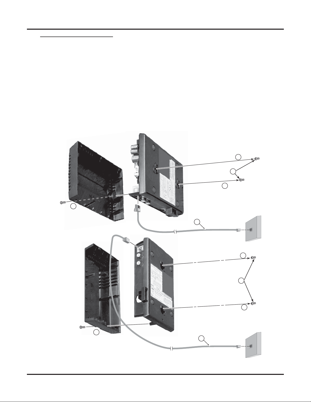
Installing a DSX Analog Door Box and 2PGDAD Module
Mounting the 2PGDAD Module and Connecting to the System
To mount and connect the 2PGDAD Module:
1. Mount two suitable fasteners (such as #8 sheet metal screws) about 3 15/16” apart either horizontally (for
horizontal mounting) or vertically (for vertical mounting).
- Leave the heads exposed about 1/4”
2. Place the 2PGDAD Module over the screws and slide down into place.
3. Program the Door Box and 2PGDAD Module before connecting to the 2PGDAD modular jack.
- In 1203-01: Secondary Station Port Assignment, for the 16ESIU port selected enter an available
station port for the secondary port (96-127 by default).
- In 2113-02: Ring Group, assign the extensions associated with the 2PGDAD Module and all telephones that should receive door chimes to the same Ring Group.
- Refer to the Door Box feature in the DSX Software Manual for additional programming.
4. Using a standard line cord, plug the 2PGDAD Module into its modular jack and verify the LEDs.
1093096 - 49
2
1
2
4
3
2
1
2
4
3
Figure 45: Mounting and Connecting the 2PGDAD Module
60 ◆ Optional Equipment DSX-80/160 Hardware Manual
Page 67

External Paging
Installing External Paging
The CPU provides an External Paging output. You connect the CPU Paging output to an audio input on a
customer provided Paging system. Be sure the connected Paging equipment is compatible with the following
page output specifications:
To connect to an External Paging Amplifier:
1. Obtain an audio cable that has a mono audio minijack (1/8”) on one end and a connector compatible with
the customer’s paging amplifier on the other.
2. Plug the mono audio minijack into the Audio Out connector on the CPU.
3. Plug the other end of the audio cable into the paging amplfier.
External Paging Output Specifications
Output Impedance: 600 Ohms
Output Level: 0 dBr @ 1.0 kHz
1093096 - 26
External Paging
Equipment
Optional
Audio Out
Audio Cable
To customer-provided
paging amplifier
Figure 46: Connecting External Paging
DSX-80/160 Hardware Manual Optional Equipment ◆ 61
Page 68
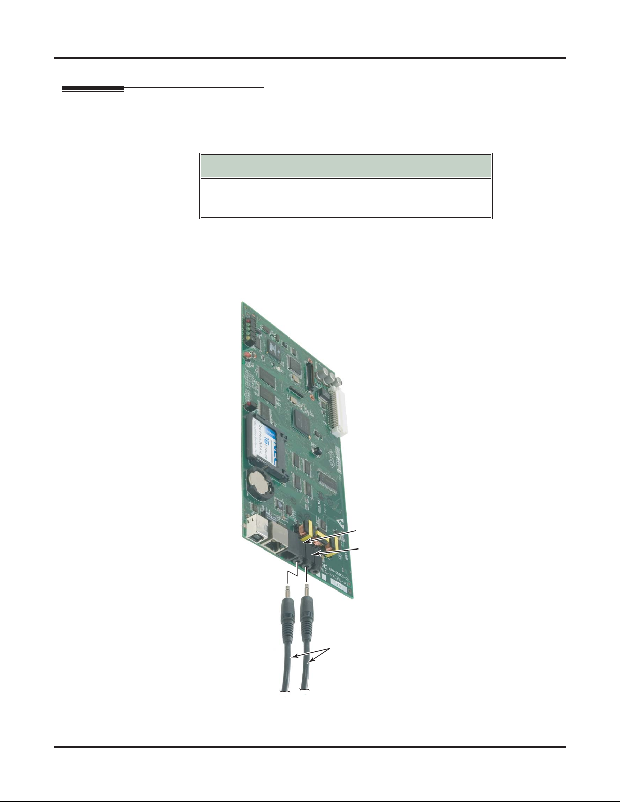
Music Source
Music Source
Installing a Music Source
Your system provides two connections for customer provided music sources. Use these music sources for
Background Music and Music on Hold. Be sure the connected music sources are compatible with the following music input specifications:
To connect a music source (two maximum):
1. Obtain an audio cable that has a mono audio minijack (1/8”) on one end and a connector compatible with
the customer’s music on the other.
2. Plug the mono audio minijack into one of the two Audio In connectors on the CPU.
3. Plug the other end of the audio cable into the music source.
Music Input Specifications
Input Impedance: 10K Ohms
Output Level: +18 dBr (+2 dBr) @ 1.0 KHz
1093096 - 27
Audio In 1
Audio In 2
Audio Cable
To customer-provided
music sources
Figure 47: Connecting a Music Source
62 ◆ Optional Equipment DSX-80/160 Hardware Manual
Page 69

Power Failure Telephone
Power Failure Cut-Through
When AC power fails, the system can automatically cut through to a Power Failure Telephone connection.
Each COIU Card has two power failure cut-though connections.
To install Power Failure Cut-Through:
1. Locate an available 8-pin jack in a line or station block.
- Local codes may prevent you from using a connector on a line block for optional equipment.
2. For the 8-pin jack chosen, locate the first two circuits in the block. If your jack is the first jack in the
block, for example:
- The first power failure circuit is the WHT/BLU - BLU/WHT pair.
- The second power failure circuit is the WHT/ORN - ORN/WHT pair.
3. Install a modular jack for each Power Failure Telephone within 6 feet of the telephone’s location.
4. For each Power Failure Telephone, run one-pair of 24 AWG station cable from the appropriate circuit on
the block to the telephone’s modular jack.
5. Terminate the station cable leads to the RED and GRN lugs in the modular jack.
6. Install bridging clips as required.
7. Plug the 8-pin connector into the power failure jack on the COIU PCB.
To test the Power Failure Telephone:
1. Connect the power failure telephone.
2. Power down the system.
3. At the Power Failure Telephone, lift the handset.
- You should hear dial tone on the line you connected.
4. Place a test call.
Power Failure Telephone
Equipment
Optional
1093096 - 28
8-Pin
Connector
GRN RED
BLK YEL
To Power
Failure
Telephone
connector on
COIU PCB
25 Pair
Installation Cable
Station
Block
625
Modular
Jack
Power Failure
Telephone 2
Figure 48: Connecting a Power Failure Telephone
BLU-WHTWHT-BLU
GRN RED
BLK YEL
625
Modular
Jack
Power Failure
Telephone 1
BLU-WHTWHT-BLU
DSX-80/160 Hardware Manual Optional Equipment ◆ 63
Page 70
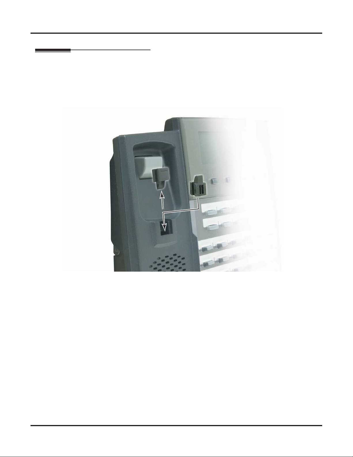
Wall Mounting
Wall Mounting
Reversing the Handset Hanger
Before wall mounting your DSX telephone, you should reverse the handset hanger. The hanger holds the
handset in place while the telephone is mounted on the wall.
To reverse the wall-mount handset hanger:
1. Slide out the handset hanger.
2. Reverse and re-insert the handset hanger.
6 - 29
10 930 9
Figure 49: Reversing the Handset Hanger
64 ◆ Optional Equipment DSX-80/160 Hardware Manual
Page 71

Wall Mounting a Keyset
Wall Mounting a Keyset on a Standard Wall Plate
To mount the telephone on the standard wall plate:
1. Locate and wire a standard wall plate in a convenient location.
2. Fold the telephone legs into the wall mount position.
3. Make sure the handset coil cord is routed through the lower channel in the base.
4. Fold the two leg supports down flush with the legs.
5. Plug a short line cord into the telephone base.
6. Plug the other end of the short line cord into the wall plate.
7. Place the telephone on top of the wall plate and slide into place.
10 930 96 - 31
Wall Mounting
1
7
Equipment
Optional
6
4
4
7
3
5
2
Figure 50: Mounting the Telephone to a Standard Wall Plate
DSX-80/160 Hardware Manual Optional Equipment ◆ 65
Page 72

Wall Mounting
Wall Mounting a Keyset Directly on the Wall
To mount the telephone directly on the wall:
1. Mount two suitable fasteners (such as #8 sheet metal screws) about 3 15/16” apart vertically.
2. Fold the telephone legs into the wall mount position.
3. Make sure the handset coil cord and line cord are routed through the lower channels in the base.
4. Fold the two leg supports down flush with the legs.
5. Place the telephone on top of the wall plate and slide into place.
6. Plug the line cord into the telephone’s mod jack.
1093096 - 30
- Leave the heads exposed about 1/4”.
5
4
4
3
2
1
5
6
Figure 51: Mounting the Telephone Directly on the Wall
66 ◆ Optional Equipment DSX-80/160 Hardware Manual
Page 73

Wall Mounting a DSS Console
Wall Mounting a DSS Console on a Standard Wall Plate
To mount the DSS Console on the standard wall plate:
1. Locate and wire a standard wall plate in a convenient location.
2. Fold the DSS Console legs into the wall mount position.
3. Fold the two leg supports down flush with the legs.
4. Plug a short line cord into the DSS Console base.
5. Plug the other end of the short line cord into the wall plate.
6. Place the DSS Console on top of the wall plate and slide into place.
Wall Mounting
1
Equipment
Optional
1093096 - 33
6
3
3
2
4
5
6
Figure 52: Mounting the DSS Console to a Standard Wall Plate
DSX-80/160 Hardware Manual Optional Equipment ◆ 67
Page 74

Wall Mounting
Wall Mounting a DSS Console Directly on the Wall
To mount the DSS Console directly on the wall:
1. Mount two suitable fasteners (such as #8 sheet metal screws) about 3 15/16” apart vertically.
2. Fold the DSS Console legs into the wall mount position.
3. Make sure the line cord is routed through the lower channel in the base.
4. Fold the two leg supports down flush with the legs.
5. Place the DSS Console on top of the wall plate and slide into place.
6. Plug the line cord into the DSS Console mod jack.
- Leave the heads exposed about 1/4”.
1093096 - 32
4
4
3
2
5
1
5
6
Figure 53: Mounting the DSS Console Directly on the Wall
68 ◆ Optional Equipment DSX-80/160 Hardware Manual
Page 75

Keyset Self Test
Testing the Keyset
Each DSX keyset has a built-in Self Test Diagnostic. Use this diagnostic to verify that each key is working,
check the lamps (LEDs) in each key, and play back some system tones.
To start the Self Test Diagnostic
1. Unplug the keyset’s line cord.
2. While pressing keys 1, 2, and 3, plug the line cord back in.
3. Continue pressing keys 1, 2, and 3 for about 10 seconds.
4. Release the keys. On the first line of the display you see:TEST PUSH
To test a key:
1. Press the key.
To test the key and Ring/Message Lamp LEDs:
1. Press Volume Up.
2. Press Volume Up again.
3. Press Volume Up a third time.
Keyset Self Test
- If you don’t see this display, repeat the procedure and hold the keys down a little longer.
- The code to the right of PUSH identifies the key (see the Key Name table below).
- Example, for Feature Key 4 you see: PUSH=L 4
- All the keys with lamps light green (except for MUTE which doesn’t have a green LED).
- All keys with lamps light red.
- All keys with lamps light orange (except for MUTE which lights red).
Equipment
Optional
To test the display:
1. Press Volume Down.
- All the elements for each character show dark.
To test some keyset tones:
1. Press Feature Keys 1, 2, or 3.
Key Name Key Name
Dial pad 0-9, * and #
Speed Dial bins 1-10
Super Display Soft Keys
CLEAR
FLASH
MUTE
INTERCOM
DND
HOLD
1
Also displays # characters for each soft key display.
D 0 - D 9, D * and D #
0 1 - 010
0 1 - 0101
F 12
F 4
F 9
F 6
F 5
F 3
To exit the Self Test Diagnostic:
1. Lift and replace the handset.
Key Names
Feature Keys 1-24
Keyset Soft Keys 1-4
CHECK
TRANSFER
REDIAL
SPEAKER
V-MAIL
CONF
L1 - L24
S 1 - S 4
F13
F 11
F 1
F 7
F 8
F 2
DSX-80/160 Hardware Manual Optional Equipment ◆ 69
Page 76
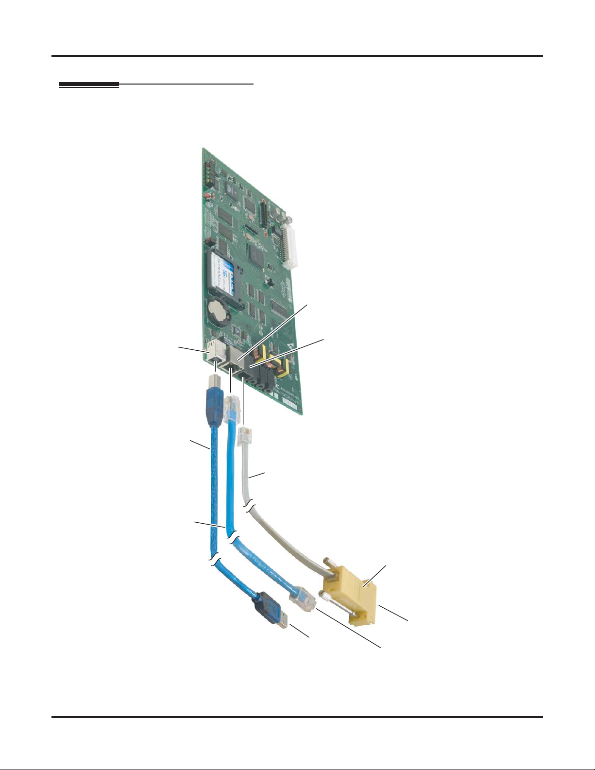
Connecting a PC to the System
Connecting a PC to the System
Connections for PC Programming (System Administrator) and SMDR
Use the USB or Ethernet port when connecting a PC locally for the System Administrator. Use the serial port
only for SMDR. Adaptor, DB9 Female to Mod 6 Jack
1093096 - 4
Ethernet (auto-sensing)
USB
Standard A-B
USB Cable
CAT 5 Cable
Serial Port
6-Conductor Line Cord
The DSX Serial Adaptor
is P/N 1091014.
DSX Serial Adaptor
To P C
To P C
USB Port
Serial Port
To P C
Ethernet Port
Figure 54: Connecting a PC to the System
70 ◆ Optional Equipment DSX-80/160 Hardware Manual
Page 77

Specifications
and Parts
Specifications
Specifications
Cabinets: 1
Talk Timeslots (Intercom/line): Non-blocking
Ports 160
Lines: 64
Digital Telephones: DSX-80: 32
Analog Telephones: DSX-80: 48
DSS Consoles: 4 max. per system
Power Failure Telephones: 2 per COIU Card
Internal Paging Zones: 8 (7 and All Call)
Specifications
and Parts
System Capacities (Page 1 of 2)
DSX-160: 96
DSX-160: 80
Plugs into a digital station port
External Page Audio Output: 1 (on CPU)
Music Inputs: 2 (on CPU)
Conference Circuits: 32 Conference circuits dynamically allocated,
with 8 parties max per Conference. Conference
circuits provided on CPU.
DSX-80/160 Hardware Manual Specifications and Parts ◆ 71
Page 78

Specifications
System Capacities (Page 2 of 2)
16ESIU Digital Station Card
16SLIU Analog Station Card
8SLIU Analog Station Card
16COIU Analog CO Line Card
8COIU Analog CO Line Card
T1/E1/PRI Card
CPU Card: 1
Environmental Requirements
Meeting established environmental standards maximizes the life of the system. Refer to the Standard Practices Manual for further information. Be sure that the site is not:
1. In direct sunlight or in hot, cold or humid places.
2. In dusty areas or in areas where sulfuric gases are produced.
3. In places where shocks or vibrations are frequent or strong.
4. In places where water or other fluids come in contact with the main equipment.
5. In areas near high-frequency machines or electric welders.
6. Near computers, telexes, microwaves, air conditioners, etc.
7. Near radio antennas (including shortwave).
Power Requirements
A dedicated 110 VAC 60 Hz circuit located within 7 feet of the cabinet is required.
Refer to System Configuration (page 19) for
capacities.
Cabinet and Key Telephones
Temperature:
Humidity:
The following specifications apply to each power supply installed.
Power Supply:
Output Power:
Input Current:
VA :
Kwh:
BTU:
Grounding Requirements:
Environmental Specifications
o
C (32-104oF)
0-40
10-95% (non-condensing)
Electrical Specifications
120 VAC + 10% @ 50-60 Hz
91 Watts @ 100% full load
1.5A @ 110V
165 VA
.165 KwH
563 BU
12 AWG copper wire
72 ◆ Specifications and Parts DSX-80/160 Hardware Manual
Page 79

Keyset Voltages
Specifications
Telephone and Line Voltages
DC voltage measured at the MDF (between tip
and ring)
Minimum operating DC voltage measured at
station jack (between tip and ring)
8/16SLIU Card Single Line Telephone Voltages
DC voltage measured at the MDF (between tip
and ring)
Ringing voltage 50-65 VAC, sinusoidal (sine wave)
High Voltage Message Waiting 95 VDC
REN (Ringer Equivalence) Per Port 2
Simultaneous Ringing Ringing cycles through the ports, ringing four
Line Voltages
Ringing voltage 42-103 VAC @ 20 Hz
Battery (from telco) 44-56 VDC
Minimum: 36 VDC
Maximum: 44 VDC
24 VDC
On-Hook Idle State Minimum: 44 VDC
On-Hook Idle State Maximum: 56 VDC
Off-Hook Active State: 7.5 VDC typical,
depending on the telephone type and loop length.
ports at a time.
Specifications
and Parts
External Paging
Output Impedance: 600 Ohm
Output Level: 0 dBr @ 1.0 KHz
DSX-80/160 Hardware Manual Specifications and Parts ◆ 73
Page 80
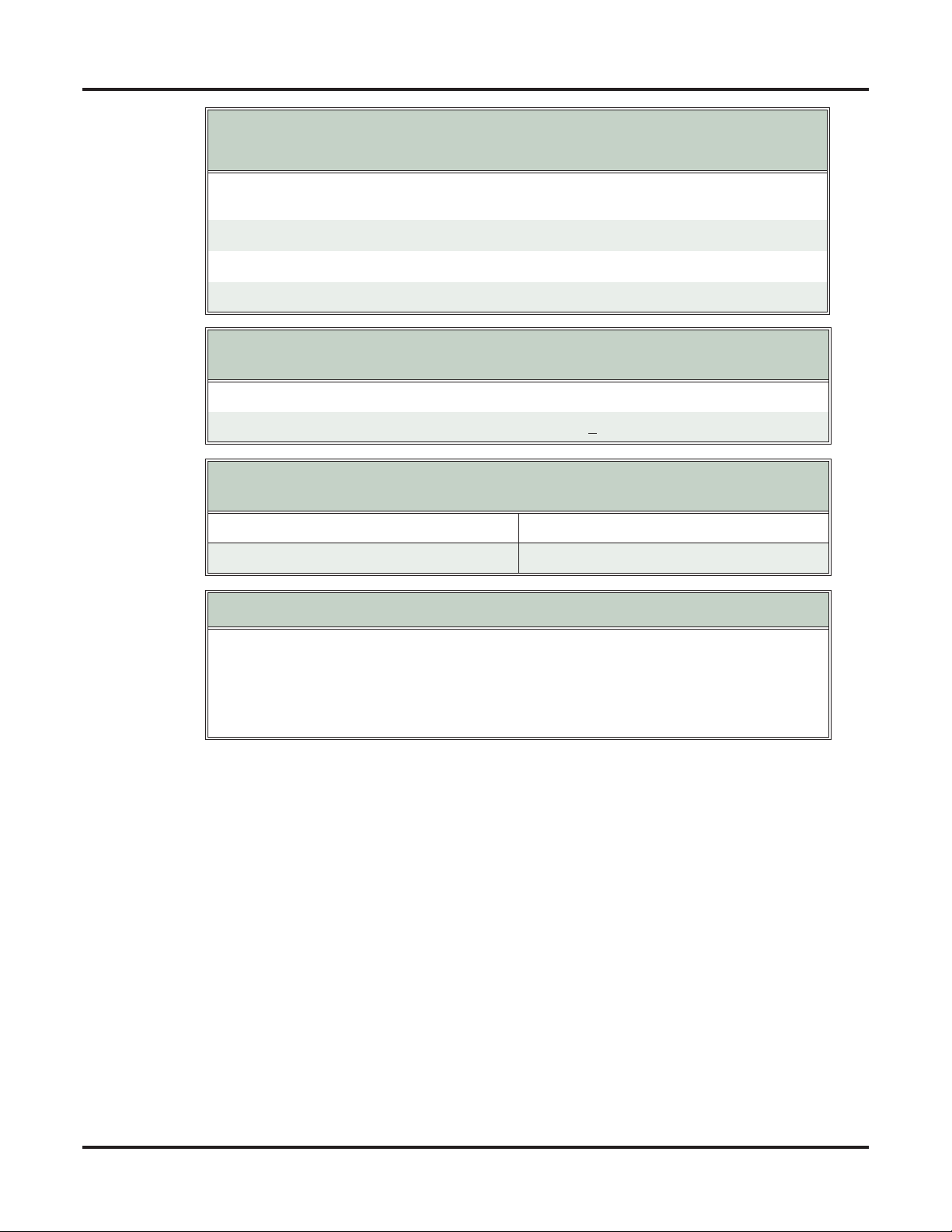
Specifications
Mechanical Specifications
Equipment Width Depth Height Weight
4 Slot KSU:
8 Slot KSU
Display Keyset: 7 5/8” 9 1/2” 4 3/4” 2 lb. 5.7 oz.
Super Display Keyset: 7 5/8” 9 1/2” 4 3/4” 2 lb. 5.7 oz.
60-Button DSS Console 5 5/8” 9 1/2” 4 3/4” 1 lb. 3.4 oz.
BGM/MOH Music Source Inputs
Music inputs are located on the CPU Card.
Input Impedance: 10K Ohms
Input Level: +18 dBr (+ 2 dBr) @ 1.0 Khz
USB and Ethernet Specifications
USB and ethernet connectors are located on the CPU Card.
USB: USB 2.0 full speed (12 Mbits/sec)
Ethernet Auto Sensing
2PGDAD Module Specifications
10 3/4”
19 1/2”
5 7/8”
5 7/8”
13 11/16”
13 11/16”
4 lbs 5 oz
6 lbs 12 oz
Relay Contacts
Configuration: Normally open
Maximum Contact Ratings: 500 mA @ 24 VDC
250 mA @ 120 VAC
74 ◆ Specifications and Parts DSX-80/160 Hardware Manual
Page 81
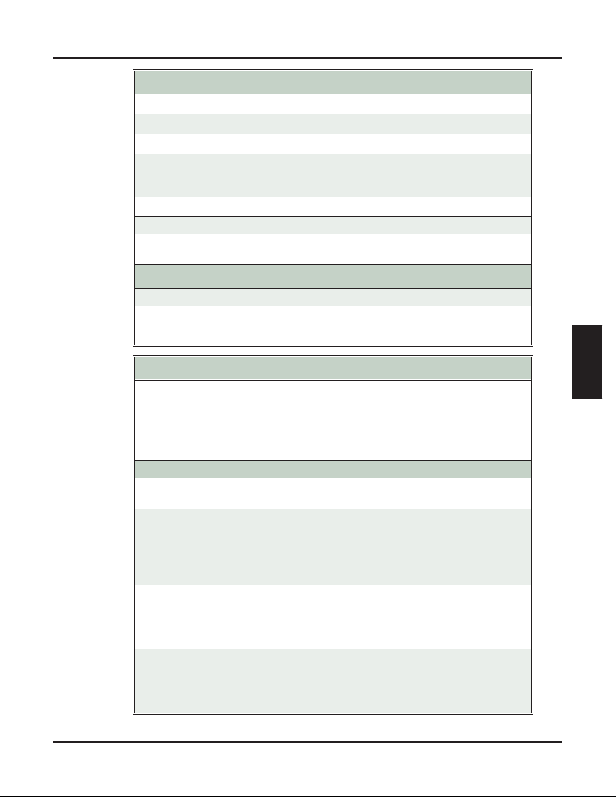
Specifications
FCC Registration Information
Model: DX7NA-80M and DSX7NA-160M
Manufacturer: NEC Infrontia
FCC Part 15 Registration: Class A
FCC Registration Number: US:NIFKF00BDSX
US:NIFMF00BDSX
US:NIFPF00BDSX
Industry Canada Certificate (DOC) Number: IC: 140k-DSX
Reg. Status FIC Mfrs. Port ID REN Network Jacks
Original 02LS2 1091005
1091009
T1/E1/PRI Card FCC Registration Information
FIC Description
REN 0.6B RJ11C
RJ21X
04DU9-BN 1.544 Mbps Superframe format (SF) without line power
04DU9-ISN 1.544 Mbps ANSI ESF and B8ZS without line power
Cabling Requirements
1. Do not run station cable parallel with the AC source, telex or computer, etc. If the cables are
near cable runs to those devices, use shielded cable with grounded shields or install the cable
in conduit.
2. When cables must be run on the floor, use cable protectors.
3. Cable runs for key telephones and single line telephones Modules must be a dedicated, isolated cable pair.
Device Cable Type Cable Run (ft) Notes
Key Telephone 2-wire 26 AWG
2-wire 24 AWG
Single Line
2-wire 26 AWG
Telephone
2-wire 24 AWG
2-wire 22 AWG
1300
2000
11,500
3150
18,000
5050
29,000
8000
at constant 20 mA
at constant 35 mA
at constant 20 mA
at constant 35 mA
at constant 20 mA
at constant 35 mA
Specifications
and Parts
2PGDAD Module 2-wire 26 AWG
2-wire 24 AWG
2-wire 22 AWG
DSX Analog Door
2-wire 26 AWG
650
980
1640
650
Box to 2PGDAD
Module
DSX-80/160 Hardware Manual Specifications and Parts ◆ 75
2-wire 24 AWG
2-wire 22 AWG
980
1640
Page 82

Parts List
Parts List
Station Equipment
Description Part Number
22-Button Display Telephone with Speakerphone 1090020 (Black)
1090025 (White)
34-Button Backlit Display Telephone with Speakerphone 1090021 (Black)
1090026 (White)
34-Button Backlit Display Telephone with Full-Duplex Speakerphone
34-Button Backlit Super Display Telephone with Half-Duplex
Speakerphone
1090022 (Black)
1090027 (White)
1090030 (Black)
1090031 (White)
60-Button DSS Console 1090024 (Black)
1090029 (White)
DTH-1-1 Single Line Telephone 780034
DTR-1-1 Single Line Telephone 780020 (Black)
780021 (White)
DTR-1HM-1 Single Line Telephone 780025 (Black)
780026 (White)
Analog Door Box 922450
2PGDAD Module 0891027
DSX Cordless Lite II Telephone
Description Part Number
Cordless Lite II Telephone 730087
Cordless Lite II Base Unit AC Adaptor 730618
Cordless Lite II Base Unit Wall Mount Bracket 730608
Cordless Lite II Handset Charger 730632
Cordless Lite II Handset Charger AC Adaptor 730619
Cordless Lite II Wall Mount Bracket for Handset Charger 730633
Cordless Lite II Handset Battery 730631
Cordless Lite II Belt Clip 730634
Cordless Lite II M175 Headset 750637
Cordless Lite II MX150 Headset 750642
76 ◆ Specifications and Parts DSX-80/160 Hardware Manual
Page 83

DESI Labels
Description Part Number
DSX Telephone Labels
DSX 22-Button Display Telephone (White) 1093086
DSX 22-Button Display Telephone (Black) 1093085
DSX 34-Button Display Telephone (White) 1093084
DSX 34-Button Display Telephone (Black) 1093083
DSX 34-Button Super Display Telephone (White) 1093082
DSX 34-Button Super Display Telephone (Black) 1093081
DSX 60-Button DSS (White) 1093080
DSX 60-Button DSS (Black) 1093079
DTR-1-1 Telephone Labels
Parts List
Black 780400
Metallic Green 780401
Metallic Silver 780402
Lime Green 780403
Preprint (blank) 780459
DTR-1HM-1 Telephone Labels
Black 780404
Metallic Green 780405
Metallic Silver 780406
Lime Green 780407
Preprint (blank) 780460
DTH-1-1 Telephone Labels
Metallic Silver 780450
DSX Telephone Headsets
Specifications
and Parts
Description Part Number
See Headsets (page 5).
DSX-80/160 Hardware Manual Specifications and Parts ◆ 77
Page 84

Parts List
Common Equipment
Description Part Number
DSX-80 4-Slot KSU
DSX-160 8-Slot KSU
1090002
1090003
DSX Power Supply 1091008
Installation Cable 808920
DSX Serial Adaptor
1091014
(requires customer-provided 6-conductor line cord)
Cards
Description Part Number
CPU Card 1090010
16 Port Digital Station Card (16ESIU) 1091004
16 Port Analog Station Card with HV Message Waiting
1091007
(16SLIU)
8 Port Analog Station Card with HV Message Waiting (8SLIU) 1091010
T1/E1/PRI Line Card 1091006
16 Port CO Line Card (16COIU) 1091005
8 Port CO Line Card (16COIU) 1091009
IntraMail
Description Part Number
IntraMail 8 Port x 16 Hour 1091013
IntraMail 4 Port x 8 Hour 1091011
78 ◆ Specifications and Parts DSX-80/160 Hardware Manual
Page 85

Replacement Parts
Description Part Number
Handset and Cord Assembly 1091016
22 Button Clear Plastic Cover 1091018
34 Button Clear Plastic Cover 1091019
34 Button Super Display Clear Plastic Cover 1091020
60 Button DSS Clear Plastic Cover 1091021
RFI Bead Kit 88901
Replacement Battery for CPU Card EX0254-0040
Parts List
Specifications
and Parts
DSX-80/160 Hardware Manual Specifications and Parts ◆ 79
Page 86

Parts List
80 ◆ Specifications and Parts DSX-80/160 Hardware Manual
Page 87

NEC Unified Solutions, Inc.
4 Forest Parkway, Shelton, CT 06484
Tel: 800-365-1928 Fax: 203-926-5458
www.necunifiedsolutions.com
Other Important Telephone Numbers
Sales: . . . . . . . . . . . . . . . . . . . . . . . . . . . . . . . . . . . .203-926-5450
Customer Service: . . . . . . . . . . . . . . . . . . . . . . . . . . .203-926-5444
Customer Service FAX: . . . . . . . . . . . . . . . . . . . . . . .203-926-5454
Technical Service: . . . . . . . . . . . . . . . . . . . . . . . . . . .203-925-8801
Discontinued Product Service: . . . . . . . . . . . . . . . . . .900-990-2541
Technical Training: . . . . . . . . . . . . . . . . . . . . . . . . . . .203-926-5430
Emergency Technical Service (After Hours): . . . . . . . .203-929-7920
(Excludes discontinued products)
Page 88

(1093096)
June 9, 2006, Rev 2
NEC Unified Solutions, Inc.
4 Forest Parkway, Shelton, CT 06484
TEL: 203-926-5400 FAX: 203-929-0535
www.necunifiedsolutions.com
Printed in U.S.A.
 Loading...