

Page 1
Digital
System
Administrator ’s Guide
Page 2

● Provides on-line viewing and printing.
● Extensive search and navigation capabilities.
● Ensures more timely turnaround of documents.
● When we provide an Acrobat manual with a product (e.g., Nitsuko TAPI Driver),
you are assured of having the most up-to-date manual available.
● With the installation of a PC fax/modem, it makes faxing of any brochure, user
guide, proposal or manual quick and easy.
● Acrobat Reader programs for Macintosh, DOS and UNIX platforms also can be
provided, if required.
● For Technical Support for the Acrobat Reader, contact:
Adobe Systems, Inc.
1585 Charleston Road
P.O. Box 7900
Mountain View, CA 94039-7900
Telephone Number: 415-961-4400
Adobe FaxY1 (technical/product information by fax): 206-628-5737
Adobe Electronic Bulletin Board (on-line information): 206-623-6984
URL: http://www.adobe.com
● To return to the opening screen, press the HOME key.
Page 3

● In Edit ➮ Preferences ➮ General, set the following:
– Default Magnification = Fit Width
– Display Splash Screen at Startup = Disabled (box not checked)
– Display Open Dialog Box at Startup = Disabled (box not checked)
● For easiest reading on-screen, select View ➮ Fit Width (or Ctrl K). This option
is automatically enabled if you set the
Default Magnification
in General
Preferences as described above.
● To return to the opening screen at any time, press Home.
To scroll up or down on a page, press PageDown or PageUp.
To navigate between pages, press –>or <–.
● To increase the speed with which your Acrobat files load, try one of the following:
– In Windows 3.1, add
ACROREAD.EXE
to your Startup Group (with the Run
Minimized box checked).
– In Windows 95, add
ACROREAD.EXE
to the Windows\Start
Menu\Programs\StartUp folder (with Run Minimized selected).
You’ll have to maximize the first Acrobat file you run.
Page 4

Contents
●
Initializing a New Digital System
●
Start-up Programming
●
Introduction
●
Features
●
Programs
Page 5

Administrator’s Guide
Digital
System
N1872ADG03
Page 6

This manual has been developed by Nitsuko America. It is intended for the use of its
customers and service personnel, and should be read in its entirety before attempting
to install or program the system. Any comments or suggestions for improving this
manual would be appreciated. Forward your remarks to:
Nitsuko America, T elecom Di vision
4 Forest Parkway
Shelton, CT 06484
Attention: Manager, Technical Publications
Nothing contained in this manual shall be deemed to be, and this manual does not
constitute, a warranty of, or representation with respect to, any of the equipment
covered. This manual is subject to change without notice and Nitsuko America has
no obligation to provide any updates or cor re ctions to this manual. Further, Nitsuko
America also reserves the right, without prior notice, to make changes in equipment
design or components as it deems appropriate. No representation is made that this
manual is complete or accurate in all respects and Nitsuko America shall not be liable
for any errors or omissions. In no event shall Nitsuko America be liable for any
incidental or consequential damages in connection with the use of this manual. This
document contains proprietary information that is protected by copyright. All rights
are reserved. No part of this document may be photocopied or reproduced without
prior written consent of Nitsuko America.
©1994 by Nitsuko America. All Rights Reserved.
Printed in U.S.A.
Page 7
Initializing a New DIGITAL SYSTEM
CAUTION: Initialization erases all the system programming
and replaces it with the factory-installed default settings.
4
9
You must initialize your system (i.e., run Program 20) before using it for the first time.
Initialization automatically enables the factory-installed Default Programming.
To initialize your system (run Program 20):
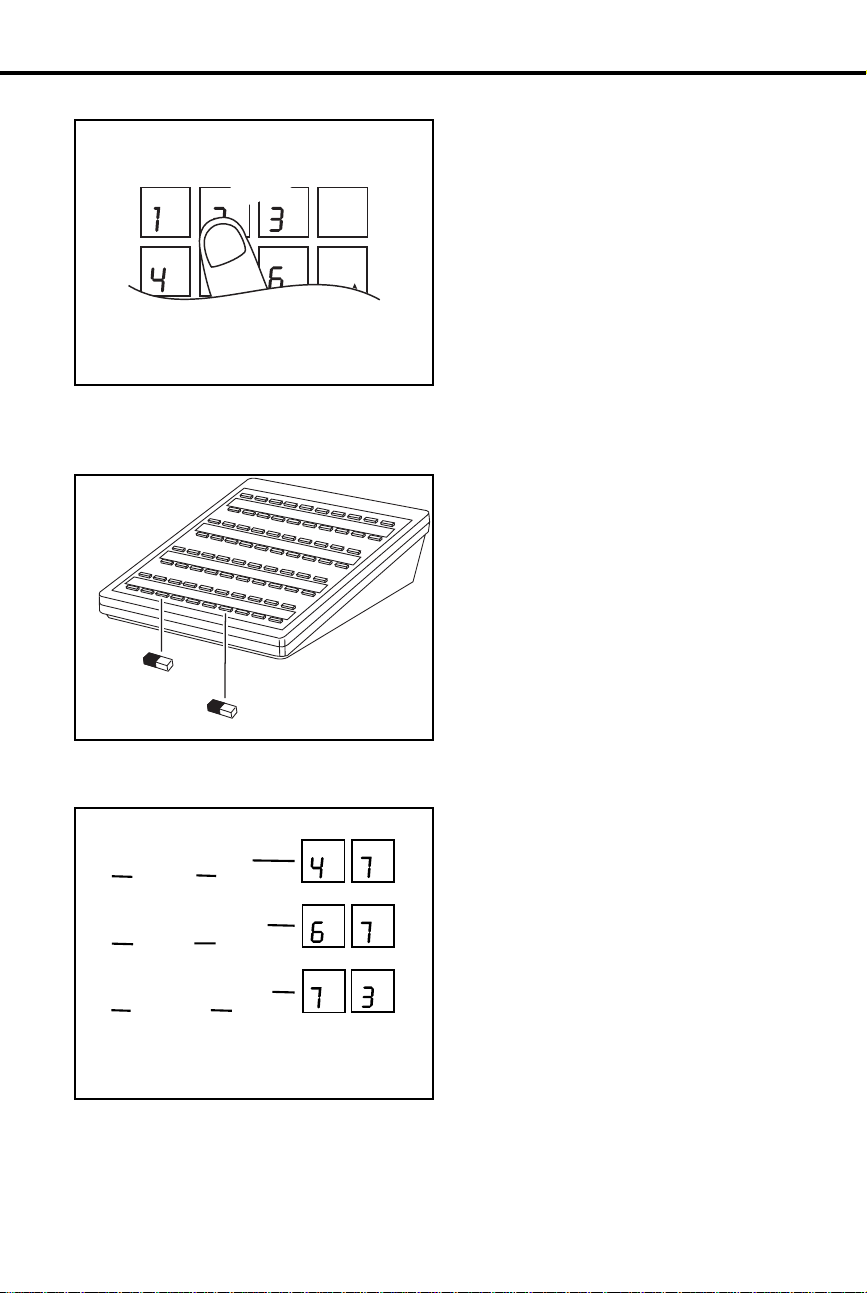
1. Install a display keyset at extension 300 (port 00).
2. Enter the programming mode.
•
Without lifting the handset, dial #775312#.
ABC
GHI
PRS
TUV
PGM
DEF
JKL
WXY
DIAL
MNO
LAST
VOL
UP
SAVE
VOL
DN
FTR
PGM PGM
PRS PRS
JKL
DEF
ABC
3. Press key 20 to select Program 20,
System Initialization
FRI 08/18 03:34P
1
2
3
4
5
GHI
PRS
11 12 13 14 15 16
10
ABC DEF
DIAL
JKL MNO
LAST
VOL
UP
WX
Y
TUV
SAVE
VOL
DN
PGM
FTR
MIC/DNDCONFHOLD ICM MSG HF
6
7
8
9
.
4. Dial 9 (for yes).
This begins initialization. All calls in progr ess will
be dropped. Wait 30 seconds before p rogramming.
5
GHI
PRS
11 12 13 14 15 16
10
ABC DEF
DIAL
JKL MNO
LAST
VOL
UP
WXY
TUV
SAVE
VOL
DN
PGM
FTR
MIC/DNDCONFHOLD ICM MSG HF
Page 8

Start-up Programming
Using the following table, you can quick l y:
Customize the programmable keys for each extension user
•
Change the way calls ring system telephones
•
Set up Voice Mail (if installed)
•
Program Speed Dial nu mb er s for extension users
•
When you first initialize, your system starts up with all ke ysets , Electronic Single Line
telephones and DSS Consoles functioning. Each extension user can place and answer
calls on all installed lines. In addition, outside calls flas h the line ke ys and ring at
extensions 300, 302 and 303. All other e xtensions flash for outsi de calls but do not ring.
❶
❷
❸
Customize an extension’s programmable keys to meet the
user’s needs.
line keys and keys 9-16 are undefined. In a 16-line system, keys 1-16 are
line keys . Turn to Programmable K eys on page 151 and Program 17 on
page 250 to f ind out more.
For example, use Program 17 to assign an extension’s keys for Park Orbits
(PO + Park Orbit 60 -6 9 + #) or Voice Mail Recor d ( RK + #) .
Set the ringing for the outside lines at each phone.
Outside Calls (Answering) on page 132, then go to Program 18 (II) on
page 263 to set ringing for extensions (RA or DRA + # + Line key + Y or
N + #). Y ou can change an extension’s Access Level in Program 15 (page
244) and allow the user to set the ringing options themselves.
Set up Voice Mail.
need to set up the following programs:
Program 14
(page 239)
Program 18 (I)
(page 256)
Program 19
(page 272)
Program 3
(page 205)
Program 12
(page 234)
For 16-button keysets in an 8-line system, keys 1-8 are
Review
If your syst em has Voice Mail (see page 185), you’ l l
Assign circuit type 51 (CIRCUIT TYPE = 51) to each
Voice Mail port.
Assign the Voice Mail feature to each Voice Mail port
(VX + # + Y + #)
Program the Voice Mail ports into a UCD hunt group.
Indicate that Voice Mail is installed and select a master
extension number (VOICE MAIL = Y + N + # then VX
MSTR EXT = Master extension + #)
Directly terminate each line the Automated Attendant
should answer (DTD or DTN + # + Master extension + #)
❹
Program System and Personal Speed Dial (see page 162).
Use Program 18 (II) (page 263) to ente r Pe r s on al an d S yst em Speed Dial
numbers. User-Programmable Features let co-workers store their own
Personal numbers. If you have an extension installed at 303, use Program
18 (I) (page 256) to assign it a Speed Dial block. Otherwise, the extension
has no Personal Speed Dial.
Page 9

Table of Contents
Introduction . . . . . . . . . . . . . . . . . . . . . . . . . . . . . . . . . . . . . . . . . . . . . . . . . . . . . . . . 1
How T o Use This Guide. . . . . . . . . . . . . . . . . . . . . . . . . . . . . . . . . . . . . . . . . . . 1
How to Use Part I . . . . . . . . . . . . . . . . . . . . . . . . . . . . . . . . . . . . . . 1
How to Use Part II (Customizing the System) . . . . . . . . . . . . . . . . 3
General Programming Tips . . . . . . . . . . . . . . . . . . . . . . . . . . . . . . . . . . . . . . . . 4
Using Your Telephone . . . . . . . . . . . . . . . . . . . . . . . . . . . . . . . . . . . . . . . . . . . . 6
The Type of Phone You Have . . . . . . . . . . . . . . . . . . . . . . . . . . . . . 6
Using a Programmable Key with Three Functions . . . . . . . . . . . . 6
If Your Phone Has an Alphanumeric Display. . . . . . . . . . . . . . . . . 7
Your Phone’s Key Lights . . . . . . . . . . . . . . . . . . . . . . . . . . . . . . . . 7
Using Handsfree Instead of the Handset . . . . . . . . . . . . . . . . . . . . 7
Dialing Codes to Use Features . . . . . . . . . . . . . . . . . . . . . . . . . . . . 8
If You Have a DSS Console . . . . . . . . . . . . . . . . . . . . . . . . . . . . . . 8
Customize with User-Programmable Features. . . . . . . . . . . . . . . . 8
Charts and Il lustrations . . . . . . . . . . . . . . . . . . . . . . . . . . . . . . . . . . . . . . . . . . 12
The System Number (Dialing) Plan . . . . . . . . . . . . . . . . . . . . . . . 12
User-Program mable Features . . . . . . . . . . . . . . . . . . . . . . . . . . . . 13
Flash Rates for Keysets with Dual Color (Red and Gree n) LEDs 14
Flash Rates for Keysets with Single Color (Red) LEDs . . . . . . . 15
Multibutton Telephone Key Layout . . . . . . . . . . . . . . . . . . . . . . . 16
Electronic Single Line (ESL) Key Callouts . . . . . . . . . . . . . . . . . 17
DSS Console Key Layout. . . . . . . . . . . . . . . . . . . . . . . . . . . . . . . 18
About Related Documents. . . . . . . . . . . . . . . . . . . . . . . . . . . . . . . . . . . . . . . . 19
Features A – H . . . . . . . . . . . . . . . . . . . . . . . . . . . . . . . . . . . . . . . . . . . . . . . . . . . . . 23
Account Codes. . . . . . . . . . . . . . . . . . . . . . . . . . . . . . . . . . . . . . . . . . . . . . . . . 23
Alarms . . . . . . . . . . . . . . . . . . . . . . . . . . . . . . . . . . . . . . . . . . . . . . . . . . . . . . . 24
Alphanumeric Display . . . . . . . . . . . . . . . . . . . . . . . . . . . . . . . . . . . . . . . . . . . 25
Alternate Attendant . . . . . . . . . . . . . . . . . . . . . . . . . . . . . . . . . . . . . . . . . . . . . 30
Analog Station Interface and Dual OPX/ASI Module . . . . . . . . . . . . . . . . . . 31
Analog Station Interface . . . . . . . . . . . . . . . . . . . . . . . . . . . . . . . . 31
Dual OPX/ ASI Module. . . . . . . . . . . . . . . . . . . . . . . . . . . . . . . . . 31
Automatic Call Distribution . . . . . . . . . . . . . . . . . . . . . . . . . . . . . . . . . . . . . . 36
Supervisor Functions . . . . . . . . . . . . . . . . . . . . . . . . . . . . . . . . . . 36
Supervisor’s DSS Console . . . . . . . . . . . . . . . . . . . . . . . . . . . . . . 36
ACD Announcements . . . . . . . . . . . . . . . . . . . . . . . . . . . . . . . . . . 37
Automatic Ringdown. . . . . . . . . . . . . . . . . . . . . . . . . . . . . . . . . . . . . . . . . . . . 39
Automatic Route Selection . . . . . . . . . . . . . . . . . . . . . . . . . . . . . . . . . . . . . . . 40
Call Routing . . . . . . . . . . . . . . . . . . . . . . . . . . . . . . . . . . . . . . . . . 40
Dialing Translation (Special Dialing Instructions) . . . . . . . . . . . 40
Time of Day Selection . . . . . . . . . . . . . . . . . . . . . . . . . . . . . . . . . 40
Hierarchical Class of Service Control . . . . . . . . . . . . . . . . . . . . . 40
Forced Authorization Code . . . . . . . . . . . . . . . . . . . . . . . . . . . . . 40
Separate Routing for Operator Assisted, International and Equal
Access Calls . . . . . . . . . . . . . . . . . . . . . . . . . . . . . . . . . . . . . . . . . 40
Independent ly P ro grammed Restri c t i on for Exchanges 976
and 555 . . . . . . . . . . . . . . . . . . . . . . . . . . . . . . . . . . . . . . . . . . . . . 40
Background Music. . . . . . . . . . . . . . . . . . . . . . . . . . . . . . . . . . . . . . . . . . . . . . 42
Battery Backup. . . . . . . . . . . . . . . . . . . . . . . . . . . . . . . . . . . . . . . . . . . . . . . . . 43
i
Page 10

Table of Contents
Call Forwarding. . . . . . . . . . . . . . . . . . . . . . . . . . . . . . . . . . . . . . . . . . . . . . . . . 44
Call Forwarding, Off-Premise. . . . . . . . . . . . . . . . . . . . . . . . . . . . . . . . . . . . . . 46
Call Forwarding System Cancel . . . . . . . . . . . . . . . . . . . . . . . . . . . . . . . . . . . . 47
Call Inter cept. . . . . . . . . . . . . . . . . . . . . . . . . . . . . . . . . . . . . . . . . . . . . . . . . . . 48
Call Timer . . . . . . . . . . . . . . . . . . . . . . . . . . . . . . . . . . . . . . . . . . . . . . . . . . . . . 49
Callback. . . . . . . . . . . . . . . . . . . . . . . . . . . . . . . . . . . . . . . . . . . . . . . . . . . . . . . 50
Caller ID . . . . . . . . . . . . . . . . . . . . . . . . . . . . . . . . . . . . . . . . . . . . . . . . . . . . . . 51
Caller ID Displays . . . . . . . . . . . . . . . . . . . . . . . . . . . . . . . . . . . . . 51
Hardware Considerations. . . . . . . . . . . . . . . . . . . . . . . . . . . . . . . . 52
Camp-On (Call Waiting) . . . . . . . . . . . . . . . . . . . . . . . . . . . . . . . . . . . . . . . . . . 55
Centrex/PBX Feature Keys . . . . . . . . . . . . . . . . . . . . . . . . . . . . . . . . . . . . . . . . 57
Class of Service. . . . . . . . . . . . . . . . . . . . . . . . . . . . . . . . . . . . . . . . . . . . . . . . . 58
Conference . . . . . . . . . . . . . . . . . . . . . . . . . . . . . . . . . . . . . . . . . . . . . . . . . . . . 60
Data . . . . . . . . . . . . . . . . . . . . . . . . . . . . . . . . . . . . . . . . . . . . . . . . . . . . . . . . . . 61
Delayed Ringing Assignment . . . . . . . . . . . . . . . . . . . . . . . . . . . . . . . . . . . . . . 62
Dialing Number Preview. . . . . . . . . . . . . . . . . . . . . . . . . . . . . . . . . . . . . . . . . . 63
Direct Inward Lines. . . . . . . . . . . . . . . . . . . . . . . . . . . . . . . . . . . . . . . . . . . . . . 64
Direct Station Selection, DSS Console. . . . . . . . . . . . . . . . . . . . . . . . . . . . . . . 66
Direct Station Selection. . . . . . . . . . . . . . . . . . . . . . . . . . . . . . . . . . . . . . . . . . . 69
Directed Call Pickup . . . . . . . . . . . . . . . . . . . . . . . . . . . . . . . . . . . . . . . . . . . . . 71
Directory Dialing . . . . . . . . . . . . . . . . . . . . . . . . . . . . . . . . . . . . . . . . . . . . . . . 72
Do Not Disturb . . . . . . . . . . . . . . . . . . . . . . . . . . . . . . . . . . . . . . . . . . . . . . . . . 74
Door Box . . . . . . . . . . . . . . . . . . . . . . . . . . . . . . . . . . . . . . . . . . . . . . . . . . . . . 75
Relay Box. . . . . . . . . . . . . . . . . . . . . . . . . . . . . . . . . . . . . . . . . . . . 75
DP and DTMF Compatibility . . . . . . . . . . . . . . . . . . . . . . . . . . . . . . . . . . . . . . 77
Pulse to Tone Conversion. . . . . . . . . . . . . . . . . . . . . . . . . . . . . . . . 77
Equal Access Compatibility . . . . . . . . . . . . . . . . . . . . . . . . . . . . . . . . . . . . . . . 79
Extended Ringing . . . . . . . . . . . . . . . . . . . . . . . . . . . . . . . . . . . . . . . . . . . . . . . 80
Extension Hunting. . . . . . . . . . . . . . . . . . . . . . . . . . . . . . . . . . . . . . . . . . . . . . . 81
Circular Hu nting . . . . . . . . . . . . . . . . . . . . . . . . . . . . . . . . . . . . . . 81
T erminal Hunting . . . . . . . . . . . . . . . . . . . . . . . . . . . . . . . . . . . . . 81
Uniform Call Distribution (UCD) . . . . . . . . . . . . . . . . . . . . . . . . . 82
External Alerti ng Device. . . . . . . . . . . . . . . . . . . . . . . . . . . . . . . . . . . . . . . . . . 84
Flash . . . . . . . . . . . . . . . . . . . . . . . . . . . . . . . . . . . . . . . . . . . . . . . . . . . . . . . . . 85
Flexible Numbering Plan . . . . . . . . . . . . . . . . . . . . . . . . . . . . . . . . . . . . . . . . . 86
Forced Line Disconnect . . . . . . . . . . . . . . . . . . . . . . . . . . . . . . . . . . . . . . . . . . 87
Group Call Pickup. . . . . . . . . . . . . . . . . . . . . . . . . . . . . . . . . . . . . . . . . . . . . . . 88
Group Listen . . . . . . . . . . . . . . . . . . . . . . . . . . . . . . . . . . . . . . . . . . . . . . . . . . . 90
Group Ringing. . . . . . . . . . . . . . . . . . . . . . . . . . . . . . . . . . . . . . . . . . . . . . . . . . 91
Handsfree . . . . . . . . . . . . . . . . . . . . . . . . . . . . . . . . . . . . . . . . . . . . . . . . . . . . . 93
Handsfree, Automati c . . . . . . . . . . . . . . . . . . . . . . . . . . . . . . . . . . . . . . . . . . . . 94
Headset . . . . . . . . . . . . . . . . . . . . . . . . . . . . . . . . . . . . . . . . . . . . . . . . . . . . . . . 95
Hold, Automatic . . . . . . . . . . . . . . . . . . . . . . . . . . . . . . . . . . . . . . . . . . . . . . . . 97
Hold, Exclusive . . . . . . . . . . . . . . . . . . . . . . . . . . . . . . . . . . . . . . . . . . . . . . . . 98
Hold, Regular . . . . . . . . . . . . . . . . . . . . . . . . . . . . . . . . . . . . . . . . . . . . . . . . . . 99
Hotline. . . . . . . . . . . . . . . . . . . . . . . . . . . . . . . . . . . . . . . . . . . . . . . . . . . . . . . 101
Features I – Z . . . . . . . . . . . . . . . . . . . . . . . . . . . . . . . . . . . . . . . . . . . . . . . . . . . . . . 103
Intercom . . . . . . . . . . . . . . . . . . . . . . . . . . . . . . . . . . . . . . . . . . . . . . . . . . . . . 103
Intrusion (Barge-In). . . . . . . . . . . . . . . . . . . . . . . . . . . . . . . . . . . . . . . . . . . . . 106
Last Number Redial . . . . . . . . . . . . . . . . . . . . . . . . . . . . . . . . . . . . . . . . . . . . 107
ii DIGITAL SYSTEM Administrator’s Guide
Page 11

Table of Contents
Line Queuing . . . . . . . . . . . . . . . . . . . . . . . . . . . . . . . . . . . . . . . . . . . . . . . . . 108
Maintenance Utilities and Reports. . . . . . . . . . . . . . . . . . . . . . . . . . . . . . . . . 11 0
Meet-Me Co nference. . . . . . . . . . . . . . . . . . . . . . . . . . . . . . . . . . . . . . . . . . . 111
Message Center . . . . . . . . . . . . . . . . . . . . . . . . . . . . . . . . . . . . . . . . . . . . . . . 112
Message Waiting . . . . . . . . . . . . . . . . . . . . . . . . . . . . . . . . . . . . . . . . . . . . . . 1 13
Micropho ne Mute . . . . . . . . . . . . . . . . . . . . . . . . . . . . . . . . . . . . . . . . . . . . . 115
Micropho ne On/Off . . . . . . . . . . . . . . . . . . . . . . . . . . . . . . . . . . . . . . . . . . . . 116
Monitor . . . . . . . . . . . . . . . . . . . . . . . . . . . . . . . . . . . . . . . . . . . . . . . . . . . . . 117
Multiple Attendants . . . . . . . . . . . . . . . . . . . . . . . . . . . . . . . . . . . . . . . . . . . . 118
Music On Hold. . . . . . . . . . . . . . . . . . . . . . . . . . . . . . . . . . . . . . . . . . . . . . . . 120
Night Answer (Off-Hours Ringing). . . . . . . . . . . . . . . . . . . . . . . . . . . . . . . . 121
Night Rin g ing . . . . . . . . . . . . . . . . . . . . . . . . . . . . . . . . . . . . . . . . . . . . . . . . 124
Non-Blocking Architecture . . . . . . . . . . . . . . . . . . . . . . . . . . . . . . . . . . . . . . 12 5
Off-Hook Signaling/Whisper Page . . . . . . . . . . . . . . . . . . . . . . . . . . . . . . . . 126
Whisper Page . . . . . . . . . . . . . . . . . . . . . . . . . . . . . . . . . . . . . . . 126
Off-Hook Ring ing. . . . . . . . . . . . . . . . . . . . . . . . . . . . . . . . . . . . 126
Operator Assistance . . . . . . . . . . . . . . . . . . . . . . . . . . . . . . . . . . . . . . . . . . . . 128
Caller Dial ing Options . . . . . . . . . . . . . . . . . . . . . . . . . . . . . . . . 128
Simultaneous Call Answering. . . . . . . . . . . . . . . . . . . . . . . . . . . 128
Programmable OPA Messages . . . . . . . . . . . . . . . . . . . . . . . . . . 128
Automatic Attendant Overflow . . . . . . . . . . . . . . . . . . . . . . . . . 129
Other Common Carriers . . . . . . . . . . . . . . . . . . . . . . . . . . . . . . . . . . . . . . . . 131
Outside Calls, Answering . . . . . . . . . . . . . . . . . . . . . . . . . . . . . . . . . . . . . . . 132
Outside Calls, Placing . . . . . . . . . . . . . . . . . . . . . . . . . . . . . . . . . . . . . . . . . . 134
Using a Line Key . . . . . . . . . . . . . . . . . . . . . . . . . . . . . . . . . . . . 134
Using Prim e Line . . . . . . . . . . . . . . . . . . . . . . . . . . . . . . . . . . . . 134
Using Line Dial-Up . . . . . . . . . . . . . . . . . . . . . . . . . . . . . . . . . . 134
Using Direct Line (Trunk) Access . . . . . . . . . . . . . . . . . . . . . . . 134
Using Direct Line Group Access . . . . . . . . . . . . . . . . . . . . . . . . 134
Using PBX/ Centrex Lines . . . . . . . . . . . . . . . . . . . . . . . . . . . . . 135
Paging. . . . . . . . . . . . . . . . . . . . . . . . . . . . . . . . . . . . . . . . . . . . . . . . . . . . . . . 138
Internal Zone Paging. . . . . . . . . . . . . . . . . . . . . . . . . . . . . . . . . . 138
External Zone Paging . . . . . . . . . . . . . . . . . . . . . . . . . . . . . . . . . 138
Park . . . . . . . . . . . . . . . . . . . . . . . . . . . . . . . . . . . . . . . . . . . . . . . . . . . . . . . . 141
Peripheral Control Unit (PCU) Module . . . . . . . . . . . . . . . . . . . . . . . . . . . . 143
Personal Greeting. . . . . . . . . . . . . . . . . . . . . . . . . . . . . . . . . . . . . . . . . . . . . . 145
Power Failure Telephone . . . . . . . . . . . . . . . . . . . . . . . . . . . . . . . . . . . . . . . . 147
Privacy . . . . . . . . . . . . . . . . . . . . . . . . . . . . . . . . . . . . . . . . . . . . . . . . . . . . . . 148
Privacy Release . . . . . . . . . . . . . . . . . . . . . . . . . . . . . . . . . . . . . . . . . . . . . . . 149
Private Lines. . . . . . . . . . . . . . . . . . . . . . . . . . . . . . . . . . . . . . . . . . . . . . . . . . 150
Programmable Keys. . . . . . . . . . . . . . . . . . . . . . . . . . . . . . . . . . . . . . . . . . . . 151
Line Key . . . . . . . . . . . . . . . . . . . . . . . . . . . . . . . . . . . . . . . . . . . 151
Park Orbit . . . . . . . . . . . . . . . . . . . . . . . . . . . . . . . . . . . . . . . . . . 151
One-Touch Speed Dial . . . . . . . . . . . . . . . . . . . . . . . . . . . . . . . . 151
Hotline . . . . . . . . . . . . . . . . . . . . . . . . . . . . . . . . . . . . . . . . . . . . 151
Loop Group . . . . . . . . . . . . . . . . . . . . . . . . . . . . . . . . . . . . . . . . 151
Loop Switch . . . . . . . . . . . . . . . . . . . . . . . . . . . . . . . . . . . . . . . . 151
Pickup Group . . . . . . . . . . . . . . . . . . . . . . . . . . . . . . . . . . . . . . . 151
Call Coverage . . . . . . . . . . . . . . . . . . . . . . . . . . . . . . . . . . . . . . . 151
Page Zone . . . . . . . . . . . . . . . . . . . . . . . . . . . . . . . . . . . . . . . . . . 151
iii
Page 12

Table of Contents
Automatic Call Timer or Manual Call Timer . . . . . . . . . . . . . . . 151
Record Key . . . . . . . . . . . . . . . . . . . . . . . . . . . . . . . . . . . . . . . . . 151
Removing Lines and Extensions. . . . . . . . . . . . . . . . . . . . . . . . . . . . . . . . . . . 153
Ringing Assignments . . . . . . . . . . . . . . . . . . . . . . . . . . . . . . . . . . . . . . . . . . . 154
Ringing Line Preference . . . . . . . . . . . . . . . . . . . . . . . . . . . . . . . . . . . . . . . . . 155
Ringing Patterns . . . . . . . . . . . . . . . . . . . . . . . . . . . . . . . . . . . . . . . . . . . . . . . 156
Distinctive Ringing . . . . . . . . . . . . . . . . . . . . . . . . . . . . . . . . . . . 156
Save . . . . . . . . . . . . . . . . . . . . . . . . . . . . . . . . . . . . . . . . . . . . . . . . . . . . . . . . . 158
Selectabl e Display Messages . . . . . . . . . . . . . . . . . . . . . . . . . . . . . . . . . . . . . 159
Silent Monitor . . . . . . . . . . . . . . . . . . . . . . . . . . . . . . . . . . . . . . . . . . . . . . . . . 161
Speed Dial . . . . . . . . . . . . . . . . . . . . . . . . . . . . . . . . . . . . . . . . . . . . . . . . . . . . 162
Personal Speed Dial . . . . . . . . . . . . . . . . . . . . . . . . . . . . . . . . . . . 162
System Speed Dial . . . . . . . . . . . . . . . . . . . . . . . . . . . . . . . . . . . . 162
One-Touch Speed Dial . . . . . . . . . . . . . . . . . . . . . . . . . . . . . . . . . 162
Storing a Pause, Flash or Delay . . . . . . . . . . . . . . . . . . . . . . . . . . 163
Split . . . . . . . . . . . . . . . . . . . . . . . . . . . . . . . . . . . . . . . . . . . . . . . . . . . . . . . . . 167
Station Call Coverage . . . . . . . . . . . . . . . . . . . . . . . . . . . . . . . . . . . . . . . . . . . 169
Station Message Detail Recording . . . . . . . . . . . . . . . . . . . . . . . . . . . . . . . . . 171
System Timers. . . . . . . . . . . . . . . . . . . . . . . . . . . . . . . . . . . . . . . . . . . . . . . . . 172
Telemarketing Dial . . . . . . . . . . . . . . . . . . . . . . . . . . . . . . . . . . . . . . . . . . . . . 174
Tenant Service. . . . . . . . . . . . . . . . . . . . . . . . . . . . . . . . . . . . . . . . . . . . . . . . . 175
Time and Date . . . . . . . . . . . . . . . . . . . . . . . . . . . . . . . . . . . . . . . . . . . . . . . . . 177
Toll Restriction . . . . . . . . . . . . . . . . . . . . . . . . . . . . . . . . . . . . . . . . . . . . . . . . 178
Tone Patterns . . . . . . . . . . . . . . . . . . . . . . . . . . . . . . . . . . . . . . . . . . . . . . . . . . 180
Traffic Management Reporting. . . . . . . . . . . . . . . . . . . . . . . . . . . . . . . . . . . . 181
Transfer . . . . . . . . . . . . . . . . . . . . . . . . . . . . . . . . . . . . . . . . . . . . . . . . . . . . . . 182
Unsupervised Conference (Tandem Calls) . . . . . . . . . . . . . . . . . . . . . . . . . . . 184
Voice Mail/Automated Attendant . . . . . . . . . . . . . . . . . . . . . . . . . . . . . . . . . . 185
Call Forward to Voice Mail (Mailbox Call Forward) . . . . . . . . . 185
Mailbox Message Waiting (Leaving a Voice Message). . . . . . . . 185
Message View. . . . . . . . . . . . . . . . . . . . . . . . . . . . . . . . . . . . . . . . 185
Transfer to Voice Mail (Mailbox T ransfer) . . . . . . . . . . . . . . . . . 185
Conversation Record . . . . . . . . . . . . . . . . . . . . . . . . . . . . . . . . . . 185
Personal Answering Machine Emulatio n. . . . . . . . . . . . . . . . . . . 185
Voice Module Unit . . . . . . . . . . . . . . . . . . . . . . . . . . . . . . . . . . . . . . . . . . . . . 189
Voice Prompting Messages . . . . . . . . . . . . . . . . . . . . . . . . . . . . . . . . . . . . . . . 191
Volume Controls . . . . . . . . . . . . . . . . . . . . . . . . . . . . . . . . . . . . . . . . . . . . . . . 193
Walking Class of Service . . . . . . . . . . . . . . . . . . . . . . . . . . . . . . . . . . . . . . . . 194
Programming S y stem Options . . . . . . . . . . . . . . . . . . . . . . . . . . . . . . . . . . . . . . . . 19 7
Program 1: Class of Service . . . . . . . . . . . . . . . . . . . . . . . . . . . . . . . . . . . . . . 197
iv DIGITAL SYSTEM Administrator’s Guide
Page 13

Table of Contents
Only Intercom Calls at Night . . . . . . . . . . . . . . . . . . . . . . . . . . . 197
Off-Premise Call Forward. . . . . . . . . . . . . . . . . . . . . . . . . . . . . . 198
Break-In (Intrusion) . . . . . . . . . . . . . . . . . . . . . . . . . . . . . . . . . . 198
Camp-On to Busy Extension . . . . . . . . . . . . . . . . . . . . . . . . . . . 198
Internal Call Forwarding . . . . . . . . . . . . . . . . . . . . . . . . . . . . . . 198
Toll Restriction Level . . . . . . . . . . . . . . . . . . . . . . . . . . . . . . . . . 198
Only Local Calls (Day or Night) . . . . . . . . . . . . . . . . . . . . . . . . 198
Only Local Calls at Night . . . . . . . . . . . . . . . . . . . . . . . . . . . . . 198
Extended Ring . . . . . . . . . . . . . . . . . . . . . . . . . . . . . . . . . . . . . . 199
Callback (Line Queuing) Priority . . . . . . . . . . . . . . . . . . . . . . . 199
Direct Trunk Access and Camp-On to Busy Line . . . . . . . . . . . 199
Initiate All Call Page . . . . . . . . . . . . . . . . . . . . . . . . . . . . . . . . . 199
Access Page Zones 1-3 . . . . . . . . . . . . . . . . . . . . . . . . . . . . . . . 199
Silent Monitor . . . . . . . . . . . . . . . . . . . . . . . . . . . . . . . . . . . . . . 199
No Flash for Single Line and ACD Supervisor = Y . . . . . . . . . 199
Single Ring for ASI Calls or Only CO Calls Call Forward to
Voice Mail. . . . . . . . . . . . . . . . . . . . . . . . . . . . . . . . . . . . . . . . . . 200
Program 2: In tercom Signaling . . . . . . . . . . . . . . . . . . . . . . . . . . . . . . . . . . . 202
Call Waiting (Camp-On) Tones . . . . . . . . . . . . . . . . . . . . . . . . . 202
Handsfree Reply on Intercom Calls . . . . . . . . . . . . . . . . . . . . . . 202
Voice-Announced Intercom Calls . . . . . . . . . . . . . . . . . . . . . . . 202
Automatic Handsfree . . . . . . . . . . . . . . . . . . . . . . . . . . . . . . . . . 202
Program 3: System Features . . . . . . . . . . . . . . . . . . . . . . . . . . . . . . . . . . . . . 205
Number of Operators . . . . . . . . . . . . . . . . . . . . . . . . . . . . . . . . . 205
Operator Extension . . . . . . . . . . . . . . . . . . . . . . . . . . . . . . . . . . 205
Number of Digits in a System Speed Dial Code . . . . . . . . . . . . 205
Side Tone Test Digit . . . . . . . . . . . . . . . . . . . . . . . . . . . . . . . . . . 205
Voice Mail Installed . . . . . . . . . . . . . . . . . . . . . . . . . . . . . . . . . . 206
Voice Mail Master Extension Number . . . . . . . . . . . . . . . . . . . 206
Enable Dial-Out of # in a Speed Dial Number . . . . . . . . . . . . . 206
Dial 1 Before Area Code (NPA) Calls . . . . . . . . . . . . . . . . . . . . 206
Walking Class of Service Security Code . . . . . . . . . . . . . . . . . . 206
Play MOH for Transferred Calls . . . . . . . . . . . . . . . . . . . . . . . . 206
Baud Rate of Auxiliary Module’s Port. . . . . . . . . . . . . . . . . . . . 206
Program 4: System Timers. . . . . . . . . . . . . . . . . . . . . . . . . . . . . . . . . . . . . . . 210
(01) Park Orbit . . . . . . . . . . . . . . . . . . . . . . . . . . . . . . . . . . . . . . 210
(02) Hold Recall . . . . . . . . . . . . . . . . . . . . . . . . . . . . . . . . . . . . . 210
(03) Camp-O n . . . . . . . . . . . . . . . . . . . . . . . . . . . . . . . . . . . . . . 210
(04) Line Response . . . . . . . . . . . . . . . . . . . . . . . . . . . . . . . . . . 210
(05) Modem Reserve . . . . . . . . . . . . . . . . . . . . . . . . . . . . . . . . . 210
(06) Number of Rings Before Recall . . . . . . . . . . . . . . . . . . . . . 210
(07) Number of Delayed Rings . . . . . . . . . . . . . . . . . . . . . . . . . 211
(08) Flash Response . . . . . . . . . . . . . . . . . . . . . . . . . . . . . . . . . . 211
(09) Dial Tone Detect . . . . . . . . . . . . . . . . . . . . . . . . . . . . . . . . . 211
(10) Make . . . . . . . . . . . . . . . . . . . . . . . . . . . . . . . . . . . . . . . . . . 211
(11) Break . . . . . . . . . . . . . . . . . . . . . . . . . . . . . . . . . . . . . . . . . 212
(12) Inter d igit . . . . . . . . . . . . . . . . . . . . . . . . . . . . . . . . . . . . . . . 212
Program 5: PBX Access Codes . . . . . . . . . . . . . . . . . . . . . . . . . . . . . . . . . . . 214
Program 6: Toll Restriction . . . . . . . . . . . . . . . . . . . . . . . . . . . . . . . . . . . . . . 216
v
Page 14

Table of Contents
Active Dialpad (Continuous Dialing) . . . . . . . . . . . . . . . . . . . . . 216
Special N11 Dialing . . . . . . . . . . . . . . . . . . . . . . . . . . . . . . . . . . 216
0 + Dialing . . . . . . . . . . . . . . . . . . . . . . . . . . . . . . . . . . . . . . . . . . 217
International Dialing . . . . . . . . . . . . . . . . . . . . . . . . . . . . . . . . . . 217
Equal Access Diali ng . . . . . . . . . . . . . . . . . . . . . . . . . . . . . . . . . 217
1 + NNX Dialing with Allow/Deny Tables . . . . . . . . . . . . . . . . . 217
NNX Dialing with Allow/Deny Tables . . . . . . . . . . . . . . . . . . . . 217
NPA Dialing with Allow/D eny Tables . . . . . . . . . . . . . . . . . . . . 218
6-Digit Analysis with Allow/Deny Tables . . . . . . . . . . . . . . . . . 218
Program 7: Music and Paging. . . . . . . . . . . . . . . . . . . . . . . . . . . . . . . . . . . . . 223
Enable Background Music . . . . . . . . . . . . . . . . . . . . . . . . . . . . . 223
Enable Music on Hold . . . . . . . . . . . . . . . . . . . . . . . . . . . . . . . . . 223
External Page Zone 1 . . . . . . . . . . . . . . . . . . . . . . . . . . . . . . . . . . 223
Audible Ring Over External All Call Page . . . . . . . . . . . . . . . . . 223
External Page Zone 2 (only if Expansion CEU #1 is installed) . 224
BGM to All External Page Zones . . . . . . . . . . . . . . . . . . . . . . . . 224
Interrupted Ring Relays . . . . . . . . . . . . . . . . . . . . . . . . . . . . . . . 224
Paging and Music Gain (Volume) Over External Speakers . . . . 224
Relay 01 Owner (for the Main CEU only) . . . . . . . . . . . . . . . . . 224
Relay 02 Owner (for Expansion CEU #1 only) . . . . . . . . . . . . . 224
Program 8: Display Messages. . . . . . . . . . . . . . . . . . . . . . . . . . . . . . . . . . . . . 227
Programming Line Options . . . . . . . . . . . . . . . . . . . . . . . . . . . . . . . . . . . . . . . . . . 229
Program 10: Line Port Characteristics . . . . . . . . . . . . . . . . . . . . . . . . . . . . . . 229
Line Circuit Type . . . . . . . . . . . . . . . . . . . . . . . . . . . . . . . . . . . . . 229
Line Gain . . . . . . . . . . . . . . . . . . . . . . . . . . . . . . . . . . . . . . . . . . . 229
PBX Line . . . . . . . . . . . . . . . . . . . . . . . . . . . . . . . . . . . . . . . . . . . 229
Side Tone Test . . . . . . . . . . . . . . . . . . . . . . . . . . . . . . . . . . . . . . . 229
Line Name . . . . . . . . . . . . . . . . . . . . . . . . . . . . . . . . . . . . . . . . . . 229
Program 11: Line Groups . . . . . . . . . . . . . . . . . . . . . . . . . . . . . . . . . . . . . . . . 232
Program 12: Line Features . . . . . . . . . . . . . . . . . . . . . . . . . . . . . . . . . . . . . . . 234
Call Pickup Group . . . . . . . . . . . . . . . . . . . . . . . . . . . . . . . . . . . . 234
Toll Restrict . . . . . . . . . . . . . . . . . . . . . . . . . . . . . . . . . . . . . . . . . 234
Direct Termination (Day) . . . . . . . . . . . . . . . . . . . . . . . . . . . . . . 234
Direct Termination (Night) . . . . . . . . . . . . . . . . . . . . . . . . . . . . . 234
Class of Service . . . . . . . . . . . . . . . . . . . . . . . . . . . . . . . . . . . . . . 235
Programming Extension Options . . . . . . . . . . . . . . . . . . . . . . . . . . . . . . . . . . . . . 239
Program 14: Extension Port Char. . . . . . . . . . . . . . . . . . . . . . . . . . . . . . . . . . 239
Extension Numbering Plan for Ports 00-47 . . . . . . . . . . . . . . . . 239
Circuit Type . . . . . . . . . . . . . . . . . . . . . . . . . . . . . . . . . . . . . . . . . 239
DSS Owner Extension (For DSS Consoles Only) . . . . . . . . . . . 241
DSS Block Number (For DSS Consoles Only) . . . . . . . . . . . . . 241
Extension Name . . . . . . . . . . . . . . . . . . . . . . . . . . . . . . . . . . . . . 241
Program 15: Access Level. . . . . . . . . . . . . . . . . . . . . . . . . . . . . . . . . . . . . . . . 24 4
Program 16: Line & Group Access. . . . . . . . . . . . . . . . . . . . . . . . . . . . . . . . . 247
Program 17: Key Assignments . . . . . . . . . . . . . . . . . . . . . . . . . . . . . . . . . . . . 250
Undefined Key (UK) . . . . . . . . . . . . . . . . . . . . . . . . . . . . . . . . . . 250
Line Key (LK) . . . . . . . . . . . . . . . . . . . . . . . . . . . . . . . . . . . . . . . 250
Loop Switch (LS) . . . . . . . . . . . . . . . . . . . . . . . . . . . . . . . . . . . . 250
Loop Group (LG) . . . . . . . . . . . . . . . . . . . . . . . . . . . . . . . . . . . . 250
vi DIGITAL SYSTEM Administrator’s Guide
Page 15

Table of Contents
Park Orbit (PO) . . . . . . . . . . . . . . . . . . . . . . . . . . . . . . . . . . . . . 251
One-Touch Speed Dial Key (SD) . . . . . . . . . . . . . . . . . . . . . . . 251
Hotline (HL) . . . . . . . . . . . . . . . . . . . . . . . . . . . . . . . . . . . . . . . . 251
Group Pickup (GP) . . . . . . . . . . . . . . . . . . . . . . . . . . . . . . . . . . 251
Call Coverage (CCK) . . . . . . . . . . . . . . . . . . . . . . . . . . . . . . . . . 251
Page Zone (PO) . . . . . . . . . . . . . . . . . . . . . . . . . . . . . . . . . . . . . 251
Automatic Call Timer (CT A) . . . . . . . . . . . . . . . . . . . . . . . . . . . 251
Manual Call Timer (CTM) . . . . . . . . . . . . . . . . . . . . . . . . . . . . . 252
Record Key (RK) . . . . . . . . . . . . . . . . . . . . . . . . . . . . . . . . . . . . 252
Data Key . . . . . . . . . . . . . . . . . . . . . . . . . . . . . . . . . . . . . . . . . . . 252
Program 18: Extension Features (I). . . . . . . . . . . . . . . . . . . . . . . . . . . . . . . . 256
Do Not Disturb (DND) . . . . . . . . . . . . . . . . . . . . . . . . . . . . . . . 256
Class of Service (COS) . . . . . . . . . . . . . . . . . . . . . . . . . . . . . . . 256
Ring Group Member (RG) . . . . . . . . . . . . . . . . . . . . . . . . . . . . 256
Call Pickup Group Member (CPG) . . . . . . . . . . . . . . . . . . . . . . 256
Privacy Release Group Member (PRG) . . . . . . . . . . . . . . . . . . . 257
Off-Hook Ring ing (OHR) . . . . . . . . . . . . . . . . . . . . . . . . . . . . . 2 5 7
DSS/BLF Lamps (BLF) . . . . . . . . . . . . . . . . . . . . . . . . . . . . . . . 257
Line Dial-Up (LDU) . . . . . . . . . . . . . . . . . . . . . . . . . . . . . . . . . 257
Page Zone Member (PZ). . . . . . . . . . . . . . . . . . . . . . . . . . . . . . . 257
Extension’s (Station’s) Operator (SO) . . . . . . . . . . . . . . . . . . . . 257
Speed Dial Block (SDB) . . . . . . . . . . . . . . . . . . . . . . . . . . . . . . 257
Voice Mail (VX) . . . . . . . . . . . . . . . . . . . . . . . . . . . . . . . . . . . . 258
Dataset (DS) . . . . . . . . . . . . . . . . . . . . . . . . . . . . . . . . . . . . . . . . 258
Door Box (receive chimes) (DB) . . . . . . . . . . . . . . . . . . . . . . . . 258
Program 18: Extension Features (II) . . . . . . . . . . . . . . . . . . . . . . . . . . . . . . . 263
Day/Night Ringing Assignments (RA) . . . . . . . . . . . . . . . . . . . 263
Night Rin g ing (NR) . . . . . . . . . . . . . . . . . . . . . . . . . . . . . . . . . . 263
Delayed Ring Assignment (DRA) . . . . . . . . . . . . . . . . . . . . . . . 263
Prime Line Assignment (PLA) . . . . . . . . . . . . . . . . . . . . . . . . . . 264
Ringing Line Preference (RLP) . . . . . . . . . . . . . . . . . . . . . . . . . 264
Direct Station Selection (DSS). . . . . . . . . . . . . . . . . . . . . . . . . . 264
Hotline Key Assignments (DSS) . . . . . . . . . . . . . . . . . . . . . . . . 264
Headset Installed (HS) . . . . . . . . . . . . . . . . . . . . . . . . . . . . . . . . 264
Incoming Voice-Announ ced Call (VA). . . . . . . . . . . . . . . . . . . . 264
Voice Page (VP) Thru Speaker . . . . . . . . . . . . . . . . . . . . . . . . . 264
Whisper Page (VO). . . . . . . . . . . . . . . . . . . . . . . . . . . . . . . . . . . 265
Speed Dial (SD) . . . . . . . . . . . . . . . . . . . . . . . . . . . . . . . . . . . . . 265
Program 19: Hunt Groups . . . . . . . . . . . . . . . . . . . . . . . . . . . . . . . . . . . . . . . 272
Circular Hunt Groups . . . . . . . . . . . . . . . . . . . . . . . . . . . . . . . . 272
T erminal Hunt Groups . . . . . . . . . . . . . . . . . . . . . . . . . . . . . . . . 272
ACD and UCD Hunt Groups . . . . . . . . . . . . . . . . . . . . . . . . . . . 272
Initializing the System . . . . . . . . . . . . . . . . . . . . . . . . . . . . . . . . . . . . . . . . . . . . . . 279
Program 20 . . . . . . . . . . . . . . . . . . . . . . . . . . . . . . . . . . . . . . . . . 279
vii
Page 16

- For your notes -
Table of Contents
viii DIGITAL SYSTEM Administrator’s Guide
Page 17

How To Use This Guide
How To Use This Guide
The DIGITAL SYSTEM Administrator’s Guide is in two parts:
Part I: DIGITAL SYSTEM Features
•
Part II: DIGITAL SYSTEM Programs
•
The number plan used in this manual assumes that your system does
not have an AUX Module installed.
presented as 30 0- 34 7. To find out more abou t you r s yst e m’s number plan, and how
it changes when you i n s t all an AUX Mo du l e, review the chart on page 12.
Part I: DIGITAL SYSTEM Features
Use Part I to learn about the DIGITAL SYSTEM features. Part I describes each
feature, its operating instructions and programming requirements. The features are
arranged in alphabetic al order for easy refe re nc e.
Each feature in Part I contains the following:
An
•
Application/Benefit
Park looks like this:
Be sure a call gets sent to a person even when you don’t know
✆
what part of the building they are in.
in the leading paragraph. For example, the benefit for
Introduction
For example, extension numbers are
A
Description
•
The
•
•
•
How to Use Part I
To use Part I of this guide:
1. Read about a feature.
2. Check its
3. If the initial configuration meets your needs, you don’t hav e to do any additional
Initial Configuration
factory.
Using the Feature
Understandi ng Related Progra mm i n g
customize the feature.
programming for that feature.
OR
If the initial configuration does not meet your needs, check the required programs under the heading
in Part II.
of the feature.
describing how the feature was prog rammed at the
, which tells you how to operate the feature.
Initial Configuration
Understanding Related Programming
listing the progra ms yo u wo ul d us e to
.
and find them
Part II: DIGITAL SYSTEM Programs
Part II contains the programs you use to customize the features. This part describes
each program and its da t a co des. Part II also sh ows you how to e nte r t ho s e da t a co des
into system memory from a programming extension.
Introduction 1
Page 18

IMPORTANT
When you program the system for the first time, run Program 20 before any
others. Program 20 initializes your system. It ensures that the initial values
are installed in Programs 1-19. Failure to run Program 20 as described may
result in erratic system operation.
How To Use This Guide
The programs are arrange d in numerical order (1-20), and divided into four
categories. The first three categories are system, line, and extension programs. The
fourth category contains on l y Program 20. Program 20 resets (initializes) the
system.
Each DIGITAL SYSTEM program (1-20) in Part II includes:
A Description of its programmable options.
•
A Feature Reference for each programmable option under the heading FOR
•
FEATURE INFORMATION. Here you’ll find the DIGITAL SYSTEM feature in
Part I that is related to a programmable option.
The Initial Configuration in the leading paragraph. For example, the initial con-
•
figuration for Program 2 looks like this:
A Y means Yes or Enabled, and an N means No or Disabled.
Program 2 is initially set as follows:
✆
•
Call W aiting (Camp-On)Tones = Y
•
Handsfree Reply on Intercom Calls = Y
•
Voice-Announced Intercom Calls = Y
•
Automatic Handsfree = Y
Filling Out the Program Record Form, which lists the data codes for each pro-
•
grammable option and shows you how to enter them on the Program Record
Form (P/N N1872PRF03).
Entering Data into Memory, which provides step-by-step instructions for enter-
•
ing the data codes into memory.
Understandi ng Related Progra mm i n g listing the related DIGITAL SYSTEM
•
programs.
2 DIGITAL SYSTEM Administrator’s Guide
Page 19

IMPORTANT
When you program the system for the first time, run Program 20 before any
others. Program 20 initializes your system. It ensures that the initial values
are installed in Programs 1-19. Failure to run Program 20 as described may
result in erratic system operation.
How To Use This Guide
How to Use Part II (Customizing the System)
After you read about a feature in Part I and determine you need to customize it by
using its related programs:
1. Read about a progra m i n Part II. If you are pr og ramming the system fo r the first
time, check the initial configuration. Make sure you need to change it.
2. Go to the heading, Filling Out the Program Record Form. Enter the required
data codes on the Program Record Form.
3. Repeat steps 1-2 for each program a feature requires, and for all features you
must customize.
4. Connect a Display Phone to port 00 (extension 300). You can also program the
system from an extension that has program access level 04 (see Program 15).
5. Do the following (described in the box) if you are programming the system for
the first time. Otherwise, go to step 6.
6. Use the instructions on the Program Record Form to enter the data codes into
memory from extension 30 0. You can a ls o u s e t h e i n s t ru cti o ns provided wi th the
program (see the heading Entering Data into Memory).
Introduction 3
Page 20

To use a program:
To enter the program
mode:
To enter a program after
you enter the program
mode:
General Programming Tips
General Programming Tips
Each program has specific instructions on how to enter its data codes into memory.
There are, ho wever, four basic ste ps t o usi n g any program. Once yo u become
familiar with them, you will not need to continually refer to the specific
programming instructions.
Using a Program
Enter the program mode from extensio n 300 or any ex-
1.
tension that has program access level 04.
-You must use a Display Phone.
Enter a program.
2.
Enter the data codes using the dial pad, erase any mis-
3.
takes you make, and move through the program’s feature options.
Save and Exit.
4.
Entering the Program Mode:
Use the Display Phone at extension 300 (or an extension
with program access level 04 [see Program 15]).
Do not lift the handset.
1.
Press #.
2.
Dial SP.
3.
-The code SP stands for "System Program" and is
77 on the dial pad.
Dial 5312.
4.
-The code 5312 is the DIGITAL SYSTEM’s
password.
Press #.
5.
- If you leave the system in the program mode too
long without pressing a key or dialing a code, two
things happen: you’ll hear reorder (fast busy) tone
and the system will automatically exit the program
mode.
Entering a Program
Press the program’s key.
1.
-Programmable keys 1-16, the HOLD, CONF,
MIC/DND and ICM keys give you access to programs
1-20, respectively. Keys 1-5 are on the left, k e ys 6-10
are on the right, keys 11-16 are ri ght under the
dialpad. The HOLD (Program 17), CONF
(Program 18), MIC/DND (Program 19), and ICM
keys (Program 20) are in the last row of keys.
4 DIGITAL SYSTEM Administrator’s Guide
Page 21

To enter data after you
enter a program:
For example:
To enter the data code Y
or N (for "Yes" or "No"):
To accept (i.e., not
change) the data on
display and move to the
next feature option:
To erase a mistake:
To save and exit after
entering data:
General Programming Tips
Entering Data, E rasing Mistakes and Mo ving Through
Program Options
Dial the data.
1.
Press the # key.
2.
-This step stores the data and moves you to the next
feature option.
Dial Y or N, which is 9 or 6 on the dial pad.
1.
Press #.
2.
When you dial data for the last feature option in a program and press #, you exit the
level you are working in and return to the previous level. In some cases, "returning to
the previous level" means you exit the program and, therefore, do not have to press
the SAVE key to exit the program (see below).
Press the # key.
1.
Saving and Exiting
Dial * right after you dial the mistake but before you
1.
press the # key to store it.
-If you make an invalid data entry and press #, you
will hear reor der (fast busy) tone. You should then
dial * and re-enter data.
Press the SAVE key.
1.
-Pressing SAV E m oves you out of a program, one
level at a time.
-You may have to press SAVE several times to exit all
the way out.
Introduction 5
Page 22
Using Your Telephone
Using Your Telephone
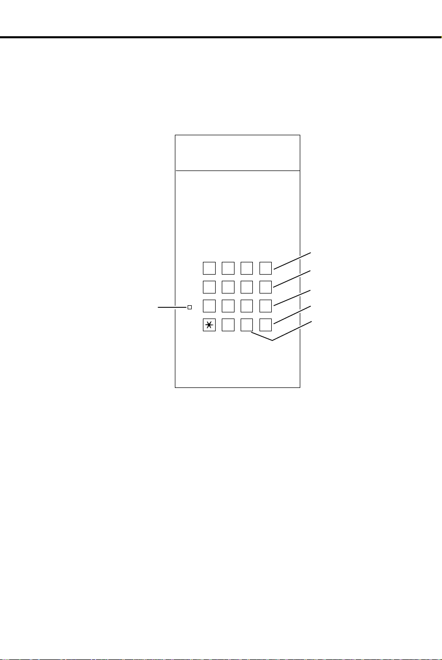
The Type of Phone Y ou Have
As the System Administrator , yo u
have a 16-button telephone (This can
also be referred to as a keyset or a
multibutton phone). Other system
users may have 16-b u t t on te l ephones
as well. Or, they may have Electronic
Single Line (E SL ) or 25 00 ty pe
(single line) telephones. Instructions
for using 16-b u t ton and ESL
telephones are included with each
feature under the heading
Feature
. For instructions on 2500 type
Using the
telephones, refer to the Analog
Station Interface feature on page 31.
Your phone has 16 programmable keys
and other feature keys that give you
one-button access to certain features.
For example, to place or answer a
Message W aiting, just press MSG. Or ,
press MIC/DND to quickly put your
phone in Do Not Disturb. For an
illustration of all the keys on your
phone and what they do, turn to page 16.
Using a Programmable K ey wit h Three Funct ions
Each of your programmable keys may have up to three functions. For example, a
single key can be a line, Speed Dial
Direct Station Selection (DSS)
ICM
DIAL
DSS
(keys 1-15)
Speed Dial
(keys 1-16)
and
key. When you just press the key,
you get its first level function (e.g.,
line key). When you press ICM, the
key automatically turns into a DSS
key. Press DIAL, and the key
becomes a Speed Dial key.
Feature
(keys 1-16)
To find out more about your
programmable keys, turn to page
151.
6 DIGITAL SYSTEM Administrator’s Guide
Page 23
If Your Phone Has an Alphanumeric Display
LL
Your telephone’s Alphanumeric
Display helps yo u us e features and
tells you about your calls. For
FRI 08/18 03:34P
example, a ringing outside line may
show you the number of the caller
before you answer. Page 25 shows all
of your phone’s displays. You can
also adjust the brightness of your
display . To find out how, turn to page
29.
Your Phone’s Ke y Lights
The lights in your phone’s keys help
you use the features. The way they
INCOMING CA
flash tells you about your call.
Depending on the mo de l of yo ur
phone, your key lights can be red or
HF
MSG
HOLD MIC/DND
ICM
CONF
both red and gree n. To find out mo re
about your key lights, turn to the
MICROPHONE
MUTE
MESSAGE
WAITING
charts on pages 14 an d 15 .
Using Your Telephone
Using Handsfree Instead of the Handset
Your telephone may ha ve a
Speakerphone for Handsfree
operation. Thi s me an s you can place
and answer calls just by pressing HF.
If your phone has Automatic
Handsfree, you can pr ess a line key
for a Handsfree call without first
pressing HF . With Monitor, you can
press HF to place a call but must lift
the handset to talk or answer. Turn to
page 93 for more on us i n g t he
Handsfree options.
Introduction 7
Page 24
Using Your Telephone
Dialing Codes to Use Features
K
C
A
B
L
L
A
C
AB
DEF
DIAL
GHI
JKL
MNO
LAST
VOL
UP
If You Have a DSS Console
ALL CALL
PAGE
You ca n call co-workers, place
outside calls and use many features by
dialing feature access codes. Often,
the code you dial is the first letter in
the feature’ s name. For example, dial
C
to leave a Callback at a busy
co-worker ’s phone. To find out the
codes to dial for outside lines and
co-workers, turn to the chart on page
12.
You ma y have a DSS Console next to
your phone. When you first use your
DSS Console, many of the keys are
programmed for you. By just pressing
a key, you can easily call (Hotline)
co-workers , Park calls or use P age.
For an illustration of the initial layout
of your DSS Console , t ur n t o page 18.
To find out more on what your DSS
Console can do, t ur n t o pa ge 66.
PARK ORBIT 60
Customize with User-Programmable Features
With your DIGITAL SYSTEM, you
can customize selected features from
your phone. For an easy-to-use chart
that shows your customizing options,
turn to page 13. Other users with the
proper access level may als o be ab l e
to customize features right from the
phone.
Head Set
Night Ring
G I
M O
N
PR
H
PR
S
P S
R
D
EF
S
Speed Dial
8 DIGITAL SYSTEM Administrator’s Guide
Page 25

Know when to use your features . . .
Calling a co-wo rke r
Outside calls
Handling and rerouti ng
your calls
When your call can’t go through
The power of digital voice
processing
Using Your Telephone
Look up what you want to do
Then turn to page
Intercom Calls.....................................103
Paging .................................................138
External Alerting Device ......................84
Automatic Ringdown............................39
Multiple Attendants ............................118
Placing and Answering .......................132
Prime Line Selection...........................134
Ringing Line Preference.....................155
Ringing Assignmen ts............. .......... ...154
Delayed Ringing................... ................62
Direct Inward Lines..............................64
Private Lines .......................................150
Account Codes......................................23
Dialing Number Preview......................63
Call Timer .............................................49
Flash........... ...................................... .....85
Centrex/PBX Feature Keys...................57
DP/DTMF Compatibility......................77
Other Common Carriers .....................131
Equal Access............ ............ ............ .....79
Music on Hold ....................................120
Handsfree..............................................93
Monitor ...............................................117
Hold.......................................................99
Split.....................................................167
Transfer...............................................182
Park.....................................................141
Call Forwarding....................................44
Selectable Display Messa ge s..............159
Volume Controls.................................193
Alphanumeric Display..........................25
Ringing Patterns..................................156
Tone Patterns.......................................180
Camp-On...............................................55
Off-Hook Signalin g................... .. .. .....126
Callback......... ...................................... .50
Line Queuing......................................108
Message W a iting.................................113
Message Center.............. .. ...................112
Voice Mail...........................................185
Whisper Page ......................................126
Intrusion..............................................106
Personal Greeting................................145
Operator Assistance ............................128
Voice Prompting Messages.................191
+
Introduction 9
Page 26

Know when to use your features . . .
Placing calls qu ic kl y
When you work in groups
If you need privacy
Have a telephone meeting
Streamlining and personalizing
your telephone
Advanced features and call
processing
Features just for attendan ts
Unique extension types
Using Your Telephone
Look up what you want to do
Then turn to page
Speed Dial .......................................... 162
Direct Stati on Selection ....................... 69
Last Number Redia l.................. .........107
Save .................................................... 158
Directory Dialing ................................. 72
Privacy Release.................................. 149
Group Call Pickup................................88
Group Ringing......... .. .. .............. ...........91
Directed Call Pickup ............................ 71
Extension Hunting............................... .81
Do Not Disturb............... ...................... 74
Microphone Mute, On/Off.................115
Headset.................................................95
Background Music............................... 42
Conference...........................................60
Unsupervised Conference .................. 184
Group Listen........ .......................... .......90
Meet Me Conference.......................... 111
Hotline................................................101
Direct Stati on Selection ....................... 69
Programmable Keys.............. .. .. .........151
Station Call Coverage ........................ 169
Automatic Call Distribution................. 36
Caller ID...................... .. .............. .........51
Telemarketing Dial............................. 174
Voice Module Unit.............................189
Walking Class of Service ................... 194
Data ...................................................... 61
Alarms .................................................. 24
Alternate Attendant..................... .........30
Silent Monitor....... .. .. .. .. .....................161
Night Answer .............. ............ ...........121
Removing Lines and Ext....................153
Forced Line Disconnect....................... 87
Time and Date .................................... 177
Call Forward System Cancel................ 47
Door and Relay Box............................. 75
Analog Station Interface ...................... 31
Dial OPX/ASI Module.........................31
PCU Module....................................... 143
+
10 DIGITAL SYSTEM Administrator’s Guide
Page 27

Know when to use your features . . .
Managing your system
Using Your Telephone
Look up what you want to do
Then turn to page
Automatic Route Selection...................40
Battery Backup.....................................43
Power Failure Telephone ....................147
Call Intercept.........................................48
Class of Service ....................................58
Extended Ringing ..... ............................80
Flexible Numbering Plan......................86
Maintenance Reports/Utilities............110
Non-Blocking System.........................125
Privacy.................................................148
SMDR.................................................171
System Ti mer s...... .... .... .... .. .... .... .... .. ...172
T enant Service.....................................175
Toll Restriction....................................178
Traffic Management............................181
+
Introduction 11
Page 28
Your System’s Dialing Plan
Charts and Illustrations
Charts and Illustrations
This section contains handy charts and illustrations for your reference. You’ll find:
The dialing plan (the numbers you dial) — see below
•
A chart for the system’s User-Programmable features — see page 13
•
Flash rates for telephones with dual color (red and green) LEDs — see page 14
•
Flash rates for telephones with single color (red) LEDs — see page 15
•
Multibutton telephone key layout — see page 16
•
Electronic Single Line (ESL) key layout — see page 17
•
DSS Console key layout (page 18)
•
The System Number (Dialing) Plan
This chart shows the numbers you dial for ext ensions, outsi de lines, Ring
Groups and Selectable Display Messages. Ask your communications
manager which system you have, so you’ll kno w which numbers to dial.
DIGITAL SYSTEM
w/o AUX
DIGITAL SYSTEM
w/AUX
Extensions
Outside Lines
Outside Line Codes
Outside Line Groups
Outside Line Extensions
PCU Extensions
Ring Groups
Selectable Display Messages
Speed Dial Bocks
(see
Speed Dial on page 16 2)
300-323 300-371
801-808 801-824
01-08 01-24
9, 90-98 9, 90-98
348-355 372-395
– 368-371
364-371 396-403
00-15 00-15
01-28 01-57
12 DIGITAL SYSTEM Administrator’s Guide
Page 29

User-Programmable Features
DIGIT AL SYSTEM USER-PROGRAMMABLE FEATURES
To program a feature, press # and the feature’s code. For example, to set
Night Ring, press # and dial NR. The remaining steps vary with each feature.
Your access level determines the features you can program. See your
communications manager. Note that enabling RA or NR disables DRA and
vice versa. To disable ringing, disable NR, RA
DELAYED RING
ASSIGNMENT
DSS
HEADSET
HOTLINE
NIGHT RING
PAGE
PRIME LINE
RING ASSIGNMENT
RINGING LINE
PREFERENCE
SPEED DIAL
TIME AND DATE
VOICE ANNOUNCE
WHISPER PAGE
Charts and Illustrations
and
DRA.
# + DRA + Line key +Y(es) or N(o) + SAVE
# + DSS + DSS key + ext. + SAVE
# + HS + Y(es) or N(o) + SAVE
# + HL + Hotline key + ext. + SAVE
# + NR + Line key +Y(es) or N(o) + SAVE
# + VP + Y(es) or N(o) + SAVE
# + PLA + Line key + Y(es) or N(o) + SAVE
# + RA + Line key + Y(es) or N(o) + SA VE
# + RLP + Y(es) or N(o) + SAVE
# + SD + One-Touch Speed key (or bin + #) +
(Display set only) Name or # + line key (or
line/group code + #) or INTERCOM + number (32
digits max.) + SAVE
# + TD + Month (01-12) + # + Date (1-31) + # +
Year (2 digits) + # + Hour (00-23) + # + Minutes
(00-59) + SAVE
# + VA + Y(es) or N(o) + SAVE
# + VO + Y(es) or N(o) + SAVE
Introduction 13
Page 30
Graphite Phone with Dual Color LEDs
Charts and Illustrations
Flash Rates for Keysets with Dual Color (Red and Green) LEDs
Your phone is idle (not on a call) All LEDs out (dark)
Outside Calls
An outside line is busy The line key is
An outside call is ringing your phone The line key flashes
And then you answer it The line key is
Or answer it with Privacy released The line key flashes
You place the outside call on Hold The line key is On then
Or a co-worker places it on Hold The line key flashes
Or you place the outside call on
Exclusive Hold
If a call on Hold recalls to you The line key is
Intercom Calls
An Intercom call rings your phone ICM flashes
You answer the Intercom call ICM flashes
You place the Intercom call on Hold HOLD flashes
And then it recalls to you ICM flashes
Miscellaneou s Fe atu r es
You activate Microphone Mute MIC/DND is
You activate Do Not Disturb MIC/DND flashes
You have a Message Waiting MSG flashes
You activate Call Forwardi ng , Personal
Greeting or Selectable Display
Messaging
shared,
Green
Flashing Green
The line key is On then
Flashing Green
Flashing Green
MSG flashes
Off
if it’s just for you
On Red
Slowly Red
Quickly Flashing
then
On Green
Quickly Green
Moderately Red
Off
then
Slowly Green
Quickly Red
Quickly Green
Slowly Green
On Red
Quickly Red
Quickly Red
Slowly Green
Slowly
Quickly
Quickly
if it’s
then
On
14 DIGITAL SYSTEM Administrator’s Guide
Page 31

Phone with Single Color (Red) LEDs
Charts and Illustrations
Flash Rates for Keysets with Single Color (Red) LEDs
Your phone is idle (not on a call) All LEDs out (dark)
Outside Calls
An outside line is busy The line key is
An outside call is ringing your phone The line key flashes
And then you answer it The line key is
Or answer it with Privacy released The line key flashes
You place the outside call on Hold The line key is On then flashing
Or a co-worker places the call on Hold The line key flashes
Or you place the outside call on
Exclusive Hold
If a call on Hold recalls to you The line key is
Intercom Calls
An Intercom call rings your phone ICM flashes
You answer the Intercom call ICM flashes
You place the Intercom call on Hold HOLD is ON then flashes
And then it recalls to you ICM flashes
Miscellaneou s Fe atu r es
You activate Microphone Mute MIC/DND is
You activate Do Not Disturb MIC/DND flashes
You have a Message Waiting MSG flashes
You activate Call Forwardi ng , Personal
Greeting or Selectable Display
Messaging
shared,
just for you
Moderately
The line key is On then flashing
Quickly
MSG flashes
On
Off
then flashing
On
Off
Slowly
Quickly
Slowly
On
Quickly
Slowly
Slowly
if it’s
Quickly
Quickly
Moderately
then flashing
Quickly
Quickly
if it’s
Quickly
Introduction 15
Page 32

Charts and Illustrations
Multibutton Telephone Key Lay out
Display
FRI 08/18 03:34P
N1870 - 16
Programmable
Feature Keys
Programmable
Feature Keys
Hold,
Background Music
Conference
1
2
3
4
5
ABC
DEF
GHI
JKL
MNO
TUV
WXY
PGM
PRS
11 12 13 14 15 16
HOLD MIC/DND ICMCONF
Do Not Disturb,
Microphone Mute
Night Answer Key
(Attendant)
DIAL
LAST
VOL
UP
SAVE
VOL
DN
FTR
MSG
10
6
7
8
9
HF
Message Waiting
Intercom
Programmable
Feature Keys
Last Number Redial
or
Volume Up
Save
or
Volume Down
Feature, Flash
Programming Mode
Handsfree
Intercom Loop Key
(Attendant)
16 DIGITAL SYSTEM Administrator’s Guide
Page 33
Electronic Single Line (ESL) Key Callouts
ABC DEF
123
GHI JKL MNO
Message
Waiting LED
456
PRS TUV WXY
7
89
PGM
0
#
Charts and Illustrations
01850L31
Transfer
TRF
VOL
UP
VOL
DN
HLD
Volume Up
Volume Down
Hold
Programming
Mode
Introduction 17
Page 34

Charts and Illustrations
DSS Console Key Layout
301 302 303 304 305 306 307 308 309 310
311 312 313 314 315 316 317 318 319 320
321 322 323 324 325 326 327 328 329 330
331 332 333 334 335 336 337 338 339 340
N1850 - 50
341 342 343 344 345 346 347
PAGE PAG 1 PAG 2 PAG 3 60 61 62 RLS
18 DIGITAL SYSTEM Administrator’s Guide
Page 35

Description
Part Number
Helps you . . .
About Related Documents
About Related Documents
Below are the other DIGITAL SYSTEM manuals and guides that you will find
useful. Peri od i cally check with your Sales Representativ e to be sure you have most
up-to-date versions.
DIGITAL SYSTEM
Program Record Form
DIGITAL SYSTEM
Hardware Manual
DIGITAL SYSTEM
Installation T e mplate
DIGITAL SYSTEM
Feature and Terminal
Programming Manual
DIGITAL SYSTEM
Multibutton T elephone
Feature Handbook
DIGITAL SYSTEM
Multibutton T elephone
Quick Reference G uide
DIGITAL SYSTEM
Electronic Single Line
User Guide
N1872PRF03 Record the data codes for each
DIGITAL SYSTEM program and
shows you how to enter the data
codes into memory
N1870INS02 Understand the DIGITAL SYSTEM
equipment and how to install it
960-592-00 Quickly install the DIGITAL
SYSTEM and get it up and running
N1870SWG03 Understa nd t he DIG I TAL SYST EM
features and shows you how to
program them from a terminal
connected to the A UX Module
N1870MFH03 Use the DIGITAL SYSTEM features
from a Multibutton Telephone
N1872MBG03 Quickly access the mos t co mmonly
used features from a Multibutton
Telephone
N1872SLO02 Quickly access the most commonly
used features from an electronic
Single Line Telepho ne
Introduction 19
Page 36

– For your notes –
About Related Documents
20 DIGITAL SYSTEM Administrator’s Guide
Page 37

Part I
DIGITAL SYSTEM Features
Part I: DIGITAL SYSTEM Features 21
Page 38

- For your notes -
22 DIGITAL SYSTEM Administrator’s Guide
Page 39

Program 3
Account Codes
Account Codes
Uniquely identify a call with a special number so it is easy to keep
✆
track of who you talked to and, if necessary, charge them for your
time.
When your system is equipped with Station Message Detail Recording (SMDR), you
can assign a 10-digit Account Code to a call. The Account Code will print out with
the other SMDR data for that call. You enter the code while placing the call or while
on the call.
For introductory information on SMDR, see page 171.
Account Codes and SMDR require the AUX Module and a customer-provided ASCII
record collection device (e.g., printer or terminal). Account Code and SMDR options
are programmed through a terminal connected to the AUX Module. For more
information, see Account Codes and SMDR in the DIGITAL SYSTEM Feature and
Terminal Programming Manual.
Initial Configuration
Account Codes not allowed
Using the Feature
N/A
Features A – H
Understanding Related Programming
To set the baud rate of the AUX Module’s port for
terminal programming (
[1200], 02 [2400], 03 [4800], 04 [9600] or 05 [19.2K] + #)
LOCAL BA UD
= 00 [300], 01
Part I: DIGITAL SYSTEM Features 23
Page 40

To View Alarms from your
attendant phone:
Program 18 (I)
Program 3
Alarms
Alarms
You can, as the attendant, quickly zero in on a system problem and
✆
report it to your service center and/or r emo v e the pr oblem line or
extension from service.
If you are an at tendant, your phone’s display m ay s h ow Alarm me s sa g es . You can
view the cause of the Alarm by pressing a single button.
You may see MINOR ALARM, MAJOR ALARM or MAJOR/MINOR ALARM. A
minor alarm occurs when an extension is unplugged or fails, or when a line fails. A
major alarm occurs wh en an e x pansion KSU (CEU) fa il s . A m ajo r/ m ino r alarm
occurs when both a ma jor and minor alar m o ccur simultaneo usl y. After you view a n
extension or line failure, you may want to remove the extension or line from service
(see page 153).
When an Alarm displays, your phone will not ring normally for incoming calls. If
your phone has Off-Hook Ringing, it rings with a single beep (repeated). If your
phone does not have Off-Hoo k Ringing, calls do not ring at all.
Initial Configuration
Alarms occur at attendant extensi o n 30 0
Using the Feature
Do not lift handset.
1.
Press MSG.
2.
-The display shows you the cause of the alarm. For
example , yo u may see STA 302 FAILED or LINE 02
FAIL ED.
Press MSG to see if there are more alarms.
3.
-When you see the first failure message again, you
have gone through the entire list.
Lift and replace handset to clear the alarms.
4.
Understanding Related Programming
To assign Off-Hook Ringing to an attendant extension so
their phone "rings" while Alarms display (
or N + #)
To assign attendant extensions (
Extension number + #)
24 DIGITAL SYSTEM Administrator’s Guide
OPR nn EXT
OHR
+ # + Y
=
Page 41

This display . . .
Appears when you . . .
Alphanumeric Display
Alphanumeric Display
See which extension is calling you, which call you are picking up,
✆
etc.
If you have a Display Phone, you see "featur e status messages" on your display when
you use your phone . For example , you see any number you dial, the extension that is
calling you, the name of the line you are answering (if names are programmed), a
recalling Transfer (when the destination extension does not answer it), etc. When
your phone is idle, the display shows you the time and date. In addition, you can
control the brightness of your display.
All the feature status display messages are listed below in alphabetical order. Some
only appear at the attendant phone , an d ar e so no ted . See also Selec tab le Display
Messages on pa ge 159 .
ACCESS DENIED Try to use compan y -wide (Sy stem Spee d Dial)
Directory Dialing from a restricted extension
ALT OPR ASSIGNED
(Attendant extension only)
B name Answer a Transfer recall from busy extension with
Bin No. = nn Dial # SD, then first digit of a Speed Dial bin
BUSY RECALL nnn Answer a Transfer recall from bu sy e xte nsion nnn
CALL FROM nnn Receive an Intercom call from extension nnn
CALL FROM Lnn Press a key to answer line nn
CALL FROM ORBI T Retrieve a call from a Park Orbit
Caller’s name Receive a call from an extension or answer a line
CANCEL ALT OPR
(Attendant extension only)
CFWD FROM nnn Receive a call forwarded from extension nnn
COMPANY WIDE DIR Dial C for compan y- wide (System Speed Dial)
CONFERENCE CALL Establish a Conference or join a call using Privacy
DATE = nn Set the Time and Date
Enable Alternate Attendant
indicated name
with indicated name
Cancel Alternate Attendant
Directory Dialing
Release
Date and Time Look at your phone while it is idle
DAY & NIGHT RING Dial # RA to program Ring Assignments
Part I: DIGITAL SYSTEM Features 25
Page 42

This display . . .
Appears when you . . .
Alphanumeric Display
DELAYED RING Dial # DRA to program Delayed Ringing
Assignment
DIAL PREVIEW Dial * to acti vate Dialing Number Preview
Digits Dial a call
DND OFF Disable Do Not Disturb
DND ON Enable Do Not Disturb
DO NOT DISTURB Call an extension in Do Not Disturb
DSS ASSIGNMENT D ial # DSS to program Direct Station Selection
DSS LAMP FIELD Press ICM
DSS, EXT, 6,9,8 ? Press ICM # (system shows you what you can do
next: press DSS key, dial extension or 6 for
Selectable Display Messages [9 & 8 not available])
EXP. KSU FAILED
(Attendant extension only)
EXT Press ICM # (with DSS suppressed) and system
F name
FWD to nnn
GROUP-R PICK-UP Answer (pick up) an outside call ringing a Ring
HEADSET = Dial # HS to program Headset operation
HF CIRCUIT BUSY Try to use Handsfree and no system Handsfree
HOLD RECALL nnn Pick up a call abandoned on Hold by extension nnn
HOLD/WAIT xx/yy Transfer a call to a busy extension that has xx calls
HOT LINES Dial # HL to program Hotline keys
HOUR = nn Set Time and Date
ICM DIRECTORY Dial I for Intercom directory
ICM NO: Press a Direct Station Selection or Hotline key to
Receive a MAJOR ALAR M fr om th e syste m that
the expansion KSU failed
shows selection options (you can dial an extension)
Place an Intercom call to an extension that has
forwarded its calls to extension nnn or to extension
with assigned name
Group (when your extension is not a member of
the group)
(Speakerphone) ci rc uits ar e available
on Hold and yy calls Camped-On (waiting)
program it
INC VOICE CALL = Dial # VA to program voice-announced Intercom
calls
26 DIGITAL SYSTEM Administrator’s Guide
Page 43

This display . . .
Appears when you . . .
Alphanumeric Display
LINE nn Answer an outside call on line nn
LINE nnn FAILED
(Attendant extension only)
MAJOR ALARM
(Attendant extension only)
MAJOR/MINOR ALRM
(Attendant extension only)
MIKE MUTED Press MIC/DND to turn off the phone ’s mic
MINOR ALARM
(Attendant extension only)
MINUTES = nn Set the Time and Date
MONTH = Set the Time and Date
MSG FRM nnn View Message Waitings and have one from
Name Place a call, answer a call, or view a Message
NIGHT MODE OFF
(Attendant extension only)
NIGHT MODE ON
(Attendant extension only)
NIGHT RING Dial # NR to program Night Ringing for lines
Press MSG to view a MINOR ALARM and line
nnn has fail ed
Receive major alarm from the system
Receive both major and minor alarms from the
system simultaneously
Receive minor alarm from the system
extension nnn
Waiting for an extension with a programmed name
Press MIC/DND to disable Night Mode operation
Press MIC/DND to enable Night Mode operation
NO RAM INSTALLED Try to use Speed Dial Dire ctory Dialing in a
NO SPEED DIAL Try to use Personal Speed Dial Directory Dialing
NO. OF MSG = nn Press MSG to check the numb er of Voice Mail
ORBIT RECALL nnn Answer a parked call that is recalling extension nnn
OUT OF AREA (Requires Caller ID) Outside caller has dialed from
P Assigned name Pick up (answer) a call for extension with assigned
PAGE THRU SPKR = Dial # VP to program paging thru the speaker
PARKED IN nn Park a call in orbit nn
Part I: DIGITAL SYSTEM Features 27
system without an AUX Module
with no Speed Dial blocks assigned in
programming
messages
an area that does not support Caller ID
name
Page 44

This display . . .
Appears when you . . .
Alphanumeric Display
PERSONAL DIR. Dial P for Personal Director y Dialin g
PICKUP FROM nnn Pick up a call ringing extension nnn
PRIME LINE Dial # PLA to program a Prime Line
PRIVACY Press line key to have Privacy
PRIVATE (Requires Caller ID) Outside caller has blocked
Caller ID
PRIVATE CALL Press a line key for a line that has Privacy enabled
PROGRAM Dial # to program a feature
R Assigned name Answer recalling line from extension with
assigned name
RELEASE PRIVACY Press a line key to release Privacy on a call for
which you previously established Privacy
RING LINE PREF = Dial # RLP to program Ringing Line Preference
RING NO ANS nnn Answer a line recalling from extension nnn
SELECT LNE/GRP Dial # SD + bin (system wants line or group no.)
SELECT IDLE LINE Press DIAL to place call (using Dial Number
Preview) and system asks you to select a line
SPEED DIAL Dial # SD to store a Speed Dial number
SPEED DIAL BINS Press DIAL to use Speed Dial
Speed Dial name Make a S p eed Dial call with a stored name
STA nnn FAILED
(Attendant extension only)
UNAVAILABLE (Requires Caller ID) The telephone company’s
UNLISTED NAME Try to access Directory Dialing and the system has
WELCOME Unplug and plug in your extension
WHISPER P AGE = Dial # VO to program Whisper Page
YEAR = nn Set Time an d Da te
Initial Configuration
All displays appear (without names) at Display phones
Receive a MINOR ALARM that extension nnn
failed
Caller ID is out of service
no names programmed
28 DIGITAL SYSTEM Administrator’s Guide
Page 45

Using the Feature
To control the brightness
(contrast) of the display:
Program 14
Program 10
Press VOL UP or VOL DN while your phone is idle
1.
(Background Musi c not playing).
Understanding Related Programming
To assign extension names so they appear in displays (See
the extension name entry procedure on page 242)
To assign line names so they appear in displays (See the
line name entry procedure on page 230)
Alphanumeric Display
Part I: DIGITAL SYSTEM Features 29
Page 46

To activate Alternate
Attendant at an attendant
extension:
To cancel Alternate
Attendant:
Program 1
Alternate Attendant
Alternate Attendant
Temporarily leave your attendant position without missing calls or
✆
asking a co-worker to take your place.
If you are an attendant, Alternate Attendant lets you send your incoming ca lls to
another extension. When you activate Alte rnate Atte ndant, outside ca lls ring your
attendant extension and the alternate extension. Intercom calls ring only the alternate
unless the alternate is busy; then they ring your attendant extension instead.
Initial Configuration
Alternate Attendant enabled for extension 300
Using the Feature
(This procedure automatically cancels a Do Not Disturb
or Call Forward condition that is active at the alternate.)
Lift handset.
1.
-If you have a One-Touch Speed Dial key, you can
press it instead of using steps 2-5.
Press ICM.
2.
Dial #.
3.
Dial alternate’ s e xtension number.
4.
-Do not dial another at tendant ex t en s i on.
Dial 3.
5.
-MSG and MIC/DND keys fl as h .
Hang up.
6.
- If the alternate activates DND after you send calls
there, the alternate assignment is canceled.
-An alternate cannot forward calls to yet another
extension.
Do not lift handset.
1.
Press MIC/DND.
2.
-MSG and MIC/DND keys go out.
Understanding Related Programming
To enable/disable Internal Call Forwarding for Class of
Service 00
disables Alternate Attendant for Class of Service 30 (the
attendant’s Class of Service).
30 DIGITAL SYSTEM Administrator’s Guide
(CFWD
+ Y or N + #) . T his en ab les or
Page 47
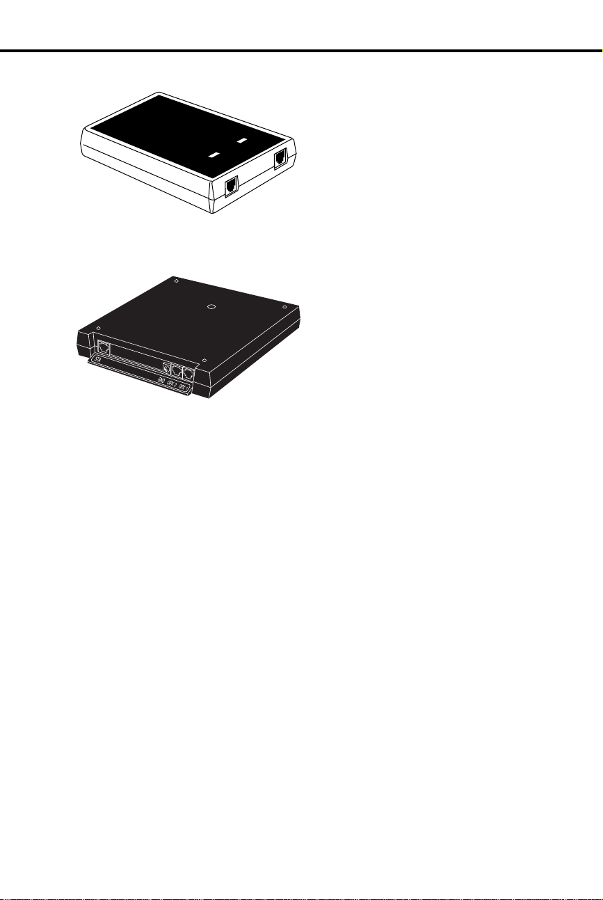
Analog Station Interface and Dual OPX/ASI Module
Analog Station Interface and Dual OPX/ASI Module
Analog Station Interface
The Analog Station Interface (ASI)
module (P/N 8974 9) provides standard
RING
LINE
01870L11
OFF-HOOK
PHONE
Dual OPX/ASI Module
DUAL OPX/ASI
1853 - 24A
numbered port in the pair. The Dual OPX/ASI Module has two internal DTMF
receivers. For installation instructions, see P/N N1853DPX05.
2500 set DTMF service at an extension
port. The 2500 set connects to the ASI
and the ASI connects to a extension port.
Each ASI module has an internal DTMF
receiver. For installation instructions, see
P/N N1850ASI03.
The Dual OPX/ASI Module (P/N
88750) provides two 2500 type DTMF
ports from a single extension
connection. The Dual OPX/ASI Mod ule
is a dual port device that connects to the
even (lower) numbered port of adjacent
even and odd numbered station por ts.
The Dual OPX/ASI uses
both
extension
positions (e.g., 304 and 305), even
though it connects only the the lowest
The ASI and Dual OPX/ASI Module are helpful when you need to install a limited
number of analog interfaces — but do not want to dedicate a line port to each one.
Other devices tha t can co nn ec t to an ASI or Dual OPX/ASI Module inclu de:
FAX machines
•
Credit card terminals
•
Modems
•
Voice Mail/Automated Attendant
•
Notes:
A connected device must:
•
– Meet FCC Part 68 requirements for Type B ringers (with a REN of 1.0 or
less). For outdialing, the device connected must provide standard DTMF
signals. The ASI provides 50 volt peak-to- peak square wave ring ing . The Dual
OPX/ASI Module provides 75 volt peak-to-peak square wave ringing.
– Not use an electromechanical ringer
– (ASI only) Be installed indoors — not off-premise with outdoor wiring)
Dual OPX/ASI circuits meet the requirements of EIA Specification RS-464-A
•
for OPS class C (loop resistance to 3,300 oh ms, loop current = 16 mA or
greater).
For each device connected to the ASI or Dual OPX/ASI Module, set its Flash
•
timer to 600-750 mS.
Initial Configuration
No ASI or Dual OPX/ASI Modules in stalle d
Part I: DIGITAL SYSTEM Features 31
Page 48

Handling Calls: The Basics
Features (In Alpha be tic al O rde r)
Analog Station Interface and Dual OPX/ASI Module
Using the Feature
The DIGITAL SYSTEM features available to th e ASI an d Du al OPX/ASI Mod ule
are listed below with abbreviated operating instructions. To find more information
on a feature, refer to the page number provided.
In the instructions that follow:
"Lift" = Lift handset.
•
"Hookflash" = hold down the hookswitch for about .5 seconds, then release it.
•
Placing an Outside Call (see
page 134)
Placing an Intercom Call
(see page 103)
Answering a Call (see page
103 and page 132)
Regular Hold (see page 99)
Transfer (see page 182)
Using Line Dial-Up: Lift + line code
(801-816) + number
Using Direct Line (Trunk) Access: Lift + line
code (348-363) + number
Using Direct Line Group Access: L ift + line
group (90-98) + nu mb er
Lift + extension or 0 for attendant
To answer any call (all calls ring): Lift
To hold: Hookfla s h + hang up
To retrieve: Lift + * 7
To retrieve call on hold at another extension:
Lift + * + extension (300-347) or line
(801-816)
To transfer: Hookflash + extension + wait for
answer + announce call + hang up
To return to call if party does not answer:
Hookflash + * 7
To recei v e a Transfer when an no un ce d: Sta y
on line (you are connected when the transferer
hangs up)
Account Codes (see page
23)
32 DIGITAL SYSTEM Administrator’s Guide
After dialing a number: # + account code + #
While on a call: Hookflash + # + account
code + # + * 7 (to return to call)
Page 49

Features (In Alpha be tic al O rde r)
Analog Station Interface and Dual OPX/ASI Module
Call Forwarding (see page
44 and page 46)
Callback (see page 50)
Camp-On (Call W aiting) ( see
page 55)
Conference (see page 60)
To an extension: Lift + # + extension +
forwarding code + hang up
Code 1: Forwar ds unanswered calls
Code 2: Forwar ds unanswered and busy calls
Code 3: Forwards all calls
To an outside number: Lift + # + 1 + line
(01-16) that calls will forward on + number to
receive calls + hang up
To cancel forwarding: Lift + # + hang up
To leave callback at busy tone: 2 + hang up
To answer ring: Lift (you get connected to
previously busy extension)
To cancel a callback: Call busy extension
again + * + hang up
To cancel all callbacks: Lift + # * + hang up
To send beeps at busy tone: 2 + wait
To answer bee ps : Hookfl ash + * 2 (see also
Split)
Establish call + hookflash + establish call +
hookflash + * #
Directed Call Pickup (see
page 71)
Flash (see page 85)
Forced Line Disconnect
(see page 87)
Group Call Pickup (see
page 88)
Group Ring (see page 91)
Intrusion (Barge-In) (see
page 106)
Last Number Redial (see
page 107)
Part I: DIGITAL SYSTEM Features 33
Lift + * + extensio n
This option is only available with AUX
Module software version 02.10 and higher.
While on an outside call:
Hookflash + 7 *
Lift + line (348-363 or 801-816 for lines
01-16) + # (to use line for a call: line +
number)
Lift + * 1
Lift + Ring Grou p (3 64 -3 71 wi thout AUX,
396-403 with AUX)
At busy tone: 4
Lift + * *
Page 50

Features (In Alpha be tic al O rde r)
Analog Station Interface and Dual OPX/ASI Module
Line Queuing (see page 108)
Meet-Me Conference (see
page 111)
Night Answer (see page 121)
Off-Hook Signaling (see
page 126)
Paging (see page 138)
Park (see page 141)
Selectable Display
Messages (see page 159)
At busy tone: 2 + hang up
To answer ring: Lift (you have outside dial
tone and can dial num be r)
To cancel one: Try to access busy line again +
* + hang up
To cancel all: Lift + # * + hang up
To set up Meet-Me: Page par ties + an no unce
Meet-Me code (11 or 12) + hookflash + 11 or
12 + do not hang up
To join Meet-Me: Lift + 11 or 12
To answer ring over page: Lift + * 0
To send at ring-busy tone: 1 + speak after
beeps or wait for answer
To make a page: Lift + 1 * - 8 * + announce +
hang up
To park your call: Hookflash + * + park orbit
(extension or 5 + 60-69) + pag e pe rson to
receive call + hang up
To pick up parked call: Lift + park orbit
To select: Lift + # 6 + message numb er 00-15
+ hang up
To cancel: Lift + # + ha ng up
Silent Monitor (see page
161)
Speed Dial (see page 162)
Split (see page 167)
Tandem Calls (see page 184)
Walking Class of Service
(see page 194)
34 DIGITAL SYSTEM Administrator’s Guide
At busy tone: 6
To store: Lift + # + Personal bin (50-5 9,
20-29) or System bin (700-799) + line (01-16)
or line group (90- 98 ) + number + hang up
To call: Lift + Personal bin or System bin
To answer waiting call (beeps): Hookflash + *
2
To split between calls: Hookflash + * 7
Establish call + hookflash + establish call +
hookflash + * # + hang up
Lift + # # + WCOS code + line (01-16) + dial
number
Page 51

Program 14
Program 1
Program 18 (I)
Analog Station Interface and Dual OPX/ASI Module
Understanding Related Programming
To assign the correct circuit type to an ASI port
(CIRCUIT TYPE = 51 + #)
To assign a single ring to all calls that ring an ASI in a
Class of Service (see also Program 18 [I]) (SINGLE
RING = Y + #)
To assign a Class of Service (from Program 1) to an
extension (COS = 00-27 + #)
Part I: DIGITAL SYSTEM Features 35
Page 52

Automatic Call Distribution
Automatic Call Distribution
The system autom a tically distribu tes ca lls to co -workers (agents) in
✆
the same department. No need to have r ec eptionist or attendant
screen and route calls for a department.
Automatic Call Distribution (ACD) uniformly distributes incoming calls among
members of a department (ACD group). Each ACD group consists of member
extensions, called agents, and a master number. When a call rings the master
number, the system automatically routes the call to the agent that has been idle (on
hook) the longest. The call can be a transferred call or Intercom call to the master
number.
Supervisor Functions
Each AC D group can ha ve a supervi s o r extension. The supervis or must have a
display telephone with a DSS Console. This lets the supervisor monitor the status of
the ACD group and each agent extension. When all ACD agents are busy, the
supervisor’s display shows:
The number of calls waiting
•
The line or extension that has been waiting the longest
•
How long the extension or line has been waiting
•
Using their DSS Console, the supervisor can also take agent extensions in and out of
service as the traffic into the ACD group changes. ACD agents can also remove and
reinstall their own extensions. However, the supervisor can always reinstall an
extension if it was removed by an agent.
Supervisor’s DSS Console
The supervisor’s DSS Console should have a Hotline ke y for e ach ACD agent. This
shows at a glance the status of each agent.
When the DSS key is... Agent is...
Off Idle
On Busy
Slow Flash Removed from service
Fast Flash In Do Not Disturb
Optionally, the supervisor’s DSS Console can have a Hotline key for the ACD master
number. This shows the status of the entire ACD group. The key lights when all
agents in the department are busy. As soon as an agent becomes free, the key goes
out.
36 DIGITAL SYSTEM Administrator’s Guide
Page 53

To remove or install a
member agent (from the
supervisor’s extension):
To remove or install
yourself as an agent
(from your agent
extension):
Program 19
Program 4
Automatic Call Distribution
ACD Announcements
ACD Annou nc e me nt s require a Voice Module Uni t (P/N 88522) an d a n AUX Module
with software versio ns 02 .1 0 or hi g he r. A C D An no uncements are not avai lable with
Base software.
An ACD group caller can optionally hear an All Agents Busy announcement when
they first call into the A CD group. This a nnouncement occurs when all ACD agents
are busy and the system autom atic ally qu eu es th e c all f or a f re e a ge nt. Th e ACD
supervisors and the attendant can customize the All Agents Busy announcement, if
desired. The system provides one All Agents Busy announcement, shared by all ACD
groups.
Notes:
Activating Call Forwarding at an ACD group extension disrupts normal hunting.
•
Activatin g Do Not Disturb (DND) at an A C D Gro up e x ten s ion tem pora rily re -
•
moves it from the group.
The ACD supervisor display timer requires a n AUX Module. If your system
•
doesn’t have an AUX Module, the supervisor’s display does not show how long
a call has been waiting for an available agent.
The supervisor cannot be the overflow destination for the ACD group.
•
With software versions A UX Module 02.10/Base 02.00 and higher, an ACD
•
agent with a headset hears silence when they place a call on Hold. With software
versions prior to AUX Module 02.10/Base 02.00, the agent hears dial tone when
they place a call on Hold. Refer to page 95 for more on Headset operation.
Initial Configuration
No ACD groups
Using the Feature
Lift handset.
1.
Press ICM.
2.
Dial #.
3.
Press DSS Console key for agent you want to change.
4.
Dial 7 to remove an agent; 4 to install.
5.
Hang up.
6.
Lift handset.
1.
Press ICM (except at an ESL set).
2.
Dial 6 to remove yourself as an agent; 4 to install.
3.
Press # and hang up.
4.
Understanding Related Programming
To set up ACD/Hunt Groups (page 272)
To set two timers: Camp-On Time (T im er 03 + # +
Duration + # – how long a call waits at a busy A CD group
before ringing the Overflow destination - if any) and
Rings Before Recall (Timer 06 + # + Duration + # – the
Part I: DIGITAL SYSTEM Features 37
Page 54

Program 17
Program 12
Automatic Call Distribution
number of time s a call rings an ACD Hunt Group
extension before going to the next one)
To assign a DSS Console Hotline key for an ACD ma ster
number (HL + Partner extension + #). The key lights
when all members are busy.
To directly terminate a lin e to an ACD master number so
calls ring it instead of having to be transferred to it (DTD
+ # + Master number + #)
38 DIGITAL SYSTEM Administrator’s Guide
Page 55

To use Automatic
Ringdown:
Automatic Ringdown
Automatic Ringdown
Call for information (for example, a reservation desk) just by
✆
lifting the handset.
Automatic Ringdown requires an AUX Module with software version 02.10 or higher.
Automatic Ringdown is not available with Base software.
With Automatic Ringdown, an ESL or 2500 set user (connecte d to an ASI or Dua l
OPX/ASI module) automatically calls a programmed destination when they lift the
handset. This would be helpful, for example in an airline terminal with dedicated
reservation phones. As soon as the caller lifts the handset, the phone rings the
reservation desk. The ringdown phone cannot access any system features (e.g.,
cannot dial digits). The ringdown phone can, however, receive calls.
Initial Configuration
Automatic Ringdown disabled.
Using the Feature
Lift handset.
1.
-You hear two beeps or ringing. If you hear ringing,
wait for the called party to answer. If you hear two
beeps, you may begin spea king.
Understanding Related Programming
Refer to the DIGITAL SYSTEM Feature and Terminal Programming Manual.
Part I: DIGITAL SYSTEM Features 39
Page 56

Automatic Route Selection
Automatic Route Selection
Calls go out on the most cost-effective routes, according to the
✆
digits users dial. For example, a call to a branch office can
automatically route over the company’s WA TS line.
Automatic Route Selection (ARS) provides call routing and call restriction based on
the digits a user dials. ARS lets you obtain the most cost-effective use of your
system’s connected long distance carriers.
ARS gives yo u o ver 8,000 call ro ut in g choices — without a cus t o m-ordered rate
structure database. You can make modifications to the routing choices quickly and
easily. This is often necessary as the cost structure of the connected services change.
Note: ARS is an on-line call routing program. You can only customize it from the
programming terminal. T o have ARS, your system must be equipped with an AUX
Module.
ARS provide s :
Call Routing
ARS can apply 3-digit (Area Code) and 6-digit (Area Code and Exchange) analysis
to every nu mb er.
Dialing T ran slation (Special Dialing Inst ructions)
ARS can automatically execute stored dialing instructions when it chooses a route
for a call.
Time of Day Selection
You ca n program route selection according to the time of day/day of week.
Hierarchical Class of Service Control
ARS allows or denies call route choices based on an extension’s Class of Service.
Forced Authorization Code
Designated routes may require the user to enter an Authorization Code before ARS
allows routing. This code is verifiable and is enforced by an extension’s Class of
Service.
Separate Routing for Operator Assisted, International and Equal Access
Calls
To provide unique control, yo u ca n program separ at e routing instruct i o ns fo r
Operator Assisted, International and Equal Access calls.
Independently Programmed Restriction for Exchanges 976 and 555
Restriction for these exchanges is hierarchical according to an extension’s Class of
Service.
Initial Configuration
ARS not installed
40 DIGITAL SYSTEM Administrator’s Guide
Page 57

To place a call using ARS:
Automatic Route Selection
Using the Feature
Lift handset. If you have an ARS loop key, press it and
1.
skip to step 4.
Press ICM (e xc ep t a t an ESL set). You hear I nt e rcom
2.
dial tone.
Dial ARS access code (9 or 90). You hear another
3.
(higher pitched) dial tone.
Dial number.
4.
Understanding Related Programming
You can only program Automatic Route Selection from the programming terminal.
Refer to the DIGITAL SYSTEM Feature and Terminal Programming Manual.
Part I: DIGITAL SYSTEM Features 41
Page 58

To turn BGM on or off
while your extension is
idle:
To adjust the volume of
BGM:
Program 7
Background Music
Background Music
Add music to your private work area to create a pleasant
✆
atmosphere.
With a touch of a key you can have Background Music (BGM) play over the speaker
of your extension while it is idle. If a page or call comes in while BGM is playing,
the music stops and starts again when the page or ringing st ops.
BGM is available only if the DIGITAL SYSTEM is equipped with an outside music
source (such as a tape player). BGM can also play over external paging speakers, if
your system is equipped and programmed for it.
Initial Configuration
BGM disabled
Using the Feature
BGM is not available to attendant extensions.
A system reset or activating Do Not Disturb automatically
turns off BGM.
Do not lift handset.
1.
Press HOLD.
2.
Press VOL UP or VOL DN while BGM is on.
1.
-This simultaneously adjusts paging and ringing
volume.
Understanding Related Programming
BGM uses line circuit #04. A line cannot be connected to it. The music source must
meet the following specifications:
Input Impedance 100 K Ohms
Maximum Input -10 dBm
To enable BGM (ENABLE BGM = Y + #)
To have music play over customer-provided external
paging speake rs , a ls o do the fo l lowing:
Enable External Page Zone 1 (EXT PAGE ZN 1 = Y)
•
Enable External Page Zone 2 i f yo u have Expa ns io n
•
CEU #1 (EXT PAGE ZN 2 = Y)
Enable BGM to All External Page Zones (BGM T O
•
PG ZN = Y).
Adjust Paging an d Mus ic Gain (Volume) Over
•
External Speakers (PG/MUSIC GAIN = 01-05)
To install external speakers, see the Hardware Manual.
42 DIGITAL SYSTEM Administrator’s Guide
Page 59

Battery Backup
Battery Backup
The DIGITAL SYSTEM performs normally during a power
✆
failure.
The Battery Backup feature automatically supplies battery power to a CEU during
AC power failures or brownouts. The recommended battery backup unit is the
Valcom VPB260, and one is required for each CEU. The VPB260 supplies power to
a fully loaded system for approximatel y tw o ho ur s .
Initial Configuration
Battery Backup allowed, but only with required equipment
Using the Feature
To install the VPB260, see the Hardware manual. Once installed, Battery Backup is
automatic during a power failure or brownout.
Understanding Related Programming
N/A
Part I: DIGITAL SYSTEM Features 43
Page 60

To forward your calls to
another extension:
Call Forwarding
Call Forwarding
Go to a meeting in a co-worker’s office and not miss your calls.
✆
Simply send them there.
Call Forwarding lets you reroute your incoming Intercom calls and some outside
calls to a co-worker’ s extension or Voice Mail. You can forward one of four types of
calls:
Ringing calls that you do not answer after a programmed number of rings
•
Ringing calls that yo u do not an s wer a fter a programmed num be r of ri ng s , an d
•
calls that try your phone when it is busy
All calls, immediately
•
Calls picked up by Voice Mail in the Personal Answering Machine Emulation
•
mode (see page 185)
Notes:
The system does not forward: Intercom calls from the forwarded destination,
•
Ring Group calls, calls that ring a Call Coverage key , and outside calls not on Direct Inward Lines.
Attendants cannot use Call Forwarding; they use Alternate Attendant (on page
•
30) instead.
Initial Configuration
Internal Call Forwarding enabled
•
A call rings an extension 5 times before being forwarded
•
Using the Feature
Call Forwarding is not available to an Alternate Attendant. See Alte rnate Attendant
on page 30 instead.
At the destination phone, do not do this to forward calls
back to your own phone; simply cancel Call Forwarding
instead.
Lift handset.
1.
-If you have a One-Touch Speed Dial key, you can
press it instead of using steps 2-5.
Press ICM (except at ESL set) and dial #.
2.
Dial extension to receive calls.
3.
-To forward your calls to Voice Mail, press MSG
instead of dialing a co-worker’ s extension. Refer to
page 185 for more on Voice Mail.
Dial Call Forward code (1,2, 3) .
4.
-Code 1 forwards ring-no-answer calls
-Code 2 forwards ring-no-answer and busy calls
-Code 3 forwards all calls
-(If forwarded to Voice Mail) Code 4 to enable
Personal Answering Machine Emu l ati o n ( s ee page
185)
Hang up.
5.
-MSG key flashes.
44 DIGITAL SYSTEM Administrator’s Guide
Page 61

To cancel Call
Forwarding:
The attendant can also cancel your Call Forwards (see
Program 1
Program 18 (I)
Program 4
Program 12
Call Forwarding Cancel on pa g e 47). A power failu re,
system reset, or activating Do Not Disturb cancels them
automatically.
Lift handset.
1.
-Press ICM (except at ESL set).
Dial # and hang up.
2.
-MSG key goes out.
Understanding Related Programming
To enable/disable Internal Call Forwarding in a Class of
Service (CALL FWD = Y or N + #) (see also Program 18
[I])
To assign a Class of Service (from Program 1) to an
extension (COS + # + 01-27 + #)
To set the Number of Rings Before Recall timer (Timer
06 + # + Duration + # – the number of times a call rings
before being forwarded)
To assign Direct Inward Li ne s to an e x ten sion (DTD + #
+ Extension number + #). Only calls on these lines will
get forwarded.
Call Forwarding
Part I: DIGITAL SYSTEM Features 45
Page 62

To forward your calls
off-premise:
To cancel Call
Forwarding:
Program 1
Program 18 (I)
Program 12
Program 16
Call Forwarding, Off-Premise
Call Forwarding, Off-Premise
Go home early in the day and have y our calls f o llow you there or to
✆
your car phone .
If your phone has Direct Inward Lines, Off-Premise Call Forwarding lets you reroute
calls on those lines to an outside telephone number.
Note: To use Call Forwarding, the DIGITAL SYSTEM must be equipped with a
Line module that provides disconnect supervision. In addition, the connected CO
line must also provide disconnect supervision.
Initial Configuration
Off-Premise Call Forw ar din g disabled
Using the Feature
Lift handset.
1.
-If you have a One-Touch Speed Dial key, you can
press it instead of using steps 2-5.
Press ICM (except at an ESL set).
2.
Dial # 1 and the line (01- 16 ) yo u wa nt yo ur c all s to fo r-
3.
ward out on.
-Use a line you have access to.
Dial telephone number to receive your calls.
4.
Hang up.
5.
-MSG key flashes slowly.
The attendant can also canc el y our Call Forwards. A
power failure, system reset, or activating Do Not Disturb
cancels them automatically.
Lift handset.
1.
Press ICM (except at an ESL set).
2.
Dial #.
3.
Hang up.
4.
-MSG key goes out.
Understanding Related Programming
To enable/disable Off-Premise Call Forwar ding in a Class
of Service (OFF-P CFWD = Y or N + #) (see also
Program 18 [I])
To assign a Class of Service (from Program 1) to an
extension (COS + # + 01-27 + #)
To assign Direct In wa rd Li ne s ( DTD + # + Extension
number)
To give an extension access to the line it will use to
forward calls out on (L + LINE NO. + # + 02 + #)
46 DIGITAL SYSTEM Administrator’s Guide
Page 63

To activate Call
Forwarding Cancel from
your attendant extension:
Program 3
Call Forwarding System Cancel
Call Forwarding System Cancel
With Call Forwarding Cancel you can, as the attendant, return the
✆
system to normal status at the end of the work day or after the
weekend so incoming calls ring their normal (not forwarded)
destinations.
If you are an attendant, Call Forwarding System Cancel lets you cancel all Call
Forwarding conditions in the system at once. Using Call Forwarding System Cancel
also cancels three other conditions system-wide: Do Not Disturbs, Personal
Greetings and Selectable Display Messages.
Initial Configuration
Call Forward Cancel allowed for attendant extension 300
Using the Feature
Lift handset.
1.
Press ICM.
2.
-ICM lights and you hear dial tone.
Press #.
3.
-Dial tone stops.
Dial *.
4.
-You hear dial tone again.
Hang up.
5.
Understanding Related Programming
Part I: DIGITAL SYSTEM Features 47
To assign attendant extensions (OPR nn EXT =
Extension number + #)
Page 64

Call Intercept
Call Intercept
Users quickly know when they dial an invalid code.
✆
Call Intercept sends fast busy tone to anyone who dials an invalid code while making
a call. In other words, the system automatically prevents (intercepts) an invalid call.
Initial Configuration
Intercept always occurs when appropriate
Using the Feature
N/A
Understanding Related Programming
N/A
48 DIGITAL SYSTEM Administrator’s Guide
Page 65

To start timing a call
when you have a Manual
Call Timer key:
To stop timing a call
before or after you hang
up:
To use the Call Timer as a
stopwatch while your
phone is idle:
Program 17
Call Timer
Call Timer
Easily keep track of how much time you spend on a call.
✆
If you have a Display Phone, the Call Timer feature lets you time your outside calls.
The duration shows on your display.
Your phone can be programmed for Automatic or Manual Call Timer:
With Automatic Call Timer, the timer automatically starts when you establish an
•
incoming or outgoing call.
With Manual Call Timer, you start the timer by pressing the Manual Call Timer
•
key .
In addition, you can use the Call Timer feature while your phone is idle to time
events, much like a stopwatch.
Note: If your system has Station Message Detail Recording (SMDR), the system
records and times your calls.
Initial Configuration
Call Ti m e r di s a bl ed (no Ti m er keys prog rammed)
Using the Feature
Press Timer key.
1.
-The key lights.
Understanding Related Programming
Part I: DIGITAL SYSTEM Features 49
Press Timer key.
1.
-The key goes out .
-T o reset the timer back to 00:00, press the Timer key
again. After a few seconds, the date and time
reappear.
Press Timer key to start and stop the stopwatch.
1.
-The key is lit while the stopwatch is on.
-To reset the timer back to 00:00 after you stop,
press the Timer key again. After a few seconds, the
date and time reappears.
To assign Automatic (Press key + CTA + #) or Manual
(Press key + CTM + #) Call Timer ke ys to an e xte nsion
Page 66

To use Callback after you
call an extension and
hear busy tone or
ring-busy tone:
To answer Callback (long)
rings:
To cancel a specific
Callback after you leave
it:
To cancel all your
Callbacks (and Line
Queuing requests):
Callback
Callback
Save time retrying a busy extension. The DIGITAL SYSTEM calls
✆
you back when it becomes idle.
When you make an Interc om call and get busy tone, you can place a Callback
request, hang up, and continue using your extension. The system then does the
following for you:
Monitors the busy extension and your extension, and calls you back (rings you)
•
when both extensions are free.
Calls the previously busy extension when you answer the "callback" ring.
•
You can leave one Callback per busy extension. For extensions with several
Callbacks, the system processes them in the order they were left.
Note: Attendants cannot use Callback.
Initial Configuration
Callback always allowed
Using the Feature
You ca nnot use Callback if you hear fast busy tone.
Dial C and hang up.
1.
You must answer within five rings or the system cancels
the Callback.
Lift handset.
1.
-This connects you to the previously busy extension.
Call the busy extension again.
1.
Dial * at busy tone and hang up.
2.
Lift handset and press ICM (except at an ESL set).
1.
At a multibutton phone, dial * and press FTR.
2.
OR
At an ESL set, dial # *.
Hang up.
3.
Understanding Related Programming
N/A
50 DIGITAL SYSTEM Administrator’s Guide
Page 67

Type of Call
Format of Display
Caller ID
Caller ID
See your callers name and number before y ou ans wer.
✆
Caller ID requires software version AUX Module 2.10/ Base 02.00 or higher.
If your phone has a display, Caller ID can show your incoming caller ’s number and
optional name. The Caller ID information will show as either a post-answer or
pre-a ns w er display. With the post-answer display, you’ll see the caller’s number and
optional name after you answer the call. The pre-answer display lets you see the
caller’s number and optional name before you answer the call. You can also use the
pre-answer display to preview incoming calls before you answer them. The Caller ID
pre-answer display is available only if your telephone does not ha ve Automatic
Handsfree (see page 94).
Caller ID supports the phone company’s Called Number Identification (CNI) and
Called Number Delivery (CND) service, when available. These se rvice s provide the
Caller ID information (i.e., messages) between the first and second rings of an
incoming call. There are two types of Caller ID message formats currently available:
Single Message Format and Multiple Message Format. With Single Message Format,
the phone company sends only the caller’s phone number (DN). The DN is either 7
or 10 digits long. In Multiple Message Format, the phone company sends the DN and
the caller’ s name. The DN for this format is also 7 or 10 digits long, and the name
provided co nsi s t s of up to 15 characters .
Once installed, Caller ID is enabled for all types of outside calls, including:
Outside calls that normally ring a phone (see Ring Assignments on page 154)
•
Calls transferred from another extension (see Transfer on page 182)
•
Calls transferred from Operato r Assistan ce v ia the Voice Module Unit (see Op-
•
erator Assi sta nc e on pa ge 12 8)
Calls transferred from Voice Mail (see Voice Mail on page 185)
•
Direct Inward Lines (DIL s ) (s e e See Direct Inward Lines on pag e 64 )
•
Assigned Night Answer (ANA) Calls (see Night Answer on pa ge 121)
•
Caller ID Displays
The Table below shows the DN format for each type of Caller ID c all:
Part I: DIGITAL SYSTEM Features 51
7-digit NNX-nnnn
8-digit nNNX-nnnn
Page 68

Message
Description
CND Trunk
Non-CND Trunk
Unscreened Transfers
Screened Transfers
Calls Transferred
by Voice Mail
Key Ring (post-answer)
& Direct Inward Lines
Caller ID
In addition to displaying the DN and name, Caller ID can also display several unique
messages received fr om the telco:
PRIVA TE Caller has blocked Caller ID.
Telco will not pass the DN.
OUT OF AREA Caller has dialed from an area
that does not support Caller ID.
UNAVAILABLE Telco’s Caller ID is out of
service.
Your system provides uni q ue displays for inc oming Caller ID (CND) an d no n- Caller
ID (non-CND) trunks. Th e inf or mation a display keyset user see s de pends on the
type of incoming trunk call and the type of trunk. The following chart describes the
telephone display for each type of incoming CND and non-CND trunk call for
software versions AUX Module 02.20/Base 02.10 and higher. For software versions
prior to AUX Module 02.20/ B as e 02.10, the tele ph on e d i spl a y always showed the
incoming trunk’s Caller ID information (for CND trunks) or programmed name (for
non-CND trunks).
Caller ID data for the
incoming trunk.
The screening extension’s
name/number, followed by
the Caller ID data for the
incoming trunk.
The Caller ID da ta for the
transferred trunk.
Caller ID data for the
incoming trunk.
Hardware Considerations
Caller ID requires the installation of at least one 4CO/CND Caller ID Module (P/N
88512). The Caller ID Module is a standard 4CO Module with additional Caller ID
capability. Each module provides Caller ID service for the lines connected to it. For
example, the inside Caller ID Module in the Main CEU provides Caller ID capability
for lines 1-4. Your system (without an AUX Module) can ha ve up to two Calle r ID
Modules, providing Caller ID capability to all eight lines.
Notes:
Caller ID requires software version AUX Module 2.10/ Base 02.00 or higher. Do
•
not install Caller ID Modules in a system that uses software prior to AUX Module 2.10/ Base 02.00. Caller ID is compatible, however, with older system databases. This allows you to upgrade software without initializing the system.
The name/numbe r fo r the
incoming trunk.
The screening extension’s
name/numbe r (even after
the screening caller hangs
up).
The transferring Voice
Mail port’s name/number.
Name/number fo r the
incoming trunk.
52 DIGITAL SYSTEM Administrator’s Guide
Page 69

Caller ID
Caller ID information prints on the SMDR report along with other call informa-
•
tion. SMDR requires an AUX Module and an SMDR collection device or
printer . Refe r to the DIGITAL SYSTEM Feature and Terminal Programming
Manual for more about SMDR.
Initial Configuration
Caller ID enabled automatically after you install a Caller ID Module.
•
Caller ID pre-answer display disabled (i.e., Automatic Handsfree enabled).
•
Part I: DIGITAL SYSTEM Features 53
Page 70

To answer a Caller ID call
(with the pre-answer
display disabled):
To answer a Caller ID call
(with the pre-answer
display enabled):
To re-display the Caller ID
information for the call
you are on:
Program 2
Caller ID
Using the Feature
Lift handset or press flashing line key.
1.
-You see the incoming caller’s name and number
and you answer the call.
(Your phone must have Automatic Handsfree disabled to
use this feature.)
Press the flashing line key to display the incoming
1.
caller’s phone number.
-You can press another flashing line key instead of
going to the next step.
Press the flashing line key again to display the incom-
2.
ing caller’s name.
-If the telephone company does not offer the name
option, you skip to the next step.
-You can press another flashing line key instead of
going to the next step.
Lift the handset to answer the call.
3.
-If you previewed several ringing lines, you’ll
answer the call on the most recently pressed line
key.
Press the line key for the call.
1.
Understanding Related Programming
To disable Automatic Handsfree (ENABL E AUTO HF =
N + #) in order to enable the Caller ID pre-answer display.
54 DIGITAL SYSTEM Administrator’s Guide
Page 71

To Camp-On to an
extension when you call it
and hear busy tone or
ring-busy tone:
To have a Transfer
Camp-On to an extension
after you call it and hear
busy or ring-busy tone:
To Camp-On to a busy
line:
Camp-On (Call Waiting)
Camp-On (Call Waiting)
Be assured that you are connected to a busy extension as soon as it
✆
becomes free.
When you make an Interc om call and get busy tone, Camp-On lets you dial a code
and wait off-hook for the busy extension to become available. Dialing the code may
send Call W a iting beeps to the busy user (if enable d in programming). The
DIGITAL SYSTEM automatically connects you to that extension when the busy user
hangs up or if the busy user chooses to interrupt their call and respond to your beeps.
When a line you want to us e is busy, Camp-On also lets you dial a c od e an d wait
off-hook for it to become free . When fr e e , th e s yst em gives yo u di a l t on e o n t h e l ine.
On the other hand, when you are busy on a call, you’ll hear Call Waiting beeps when:
An Intercom caller sends them
•
Someone transfers an outside call to you
•
You receive an outside call on a line that normally rings your phone. If several
•
calls come in while you are busy on a call, you’ll hear the beeps only for the first
one. You will not, however, hear an y Call Waiting beeps if your extension is programmed for Privacy.
Initial Configuration
All extensio ns can use Camp-On
•
Call Waiting tones enabled system-wide
•
Priv acy disable d e x cept for attendan t extension 300
•
Attendant extension 300 can Camp-On to a busy line
•
Using the Feature
Part I: DIGITAL SYSTEM Features 55
You cannot Camp-On if you hear fast busy tone (the
extension is in Do Not Disturb).
Dial C.
1.
-You hear ringing while you wait.
Do not hang up and wait to be connected.
2.
-If you choose to hang up, th e s ys tem conver t s yo ur
Camp-On to a Callback (see page 50).
Simply hang up whe n yo u he ar the busy or rin g- busy
1.
tone.
-See also Transfer on page 182.
Try to access the busy line.
1.
Dial C when you hear b u s y ton e.
2.
-Busy tone stops.
Do not hang up and wait for dial tone.
3.
-If you choose to hang up, th e s ys tem conver t s yo ur
Camp-On to a Line Queuing request (see page 108).
Page 72

To answer Call Waiting
beeps from an Intercom
call:
To answer Call Waiting
tones from an outside call:
Program 1
Program 18 (I)
Program 2
Camp-On (Call Waiting)
Your hear two beeps and ICM flashes.
At a multibutton phone, press ICM to answer the wait-
1.
ing call.
OR
At an ESL set, press HLD and dial * 2.
-Your first call goes on Hold.
-To alternate between the calls, see Split on page
167.
You hear two beeps and a Line/Loop key flashes.
Press HOLD to hold the call you are on.
1.
At a multibutton phone, press flashing Line/Loop key.
2.
OR
At an ESL set, dial * 2.
-To alternate between the calls, see Split on page
167.
Understanding Related Programming
To allow/deny Camp-On to a busy extension or line in a
Class of Service (CAMP ON or DIR ACC/CMP-ON =
Y or N + # (see also Program 18 [I])
To allow/deny Privacy in a Class of Service (PRIVACY =
Y or N + #). Allow Privacy for any extension that should
not receive Call Waiting beeps (see also Program 18 [I]).
To assign a Class of Service from Program 1 (COS + # +
01-27 + #) to an extension
To enable/disable Off-Hook Ringing at an extension
(OHR + # + Y or N + #). If enabled, th e syste m co nverts
the extension’s Call Waiting tones to a ring signal over the
speaker.
To enable/disable Call Waiting beeps system-wide
(CALL WAIT TONE = Y + #)
56 DIGITAL SYSTEM Administrator’s Guide
Page 73

Program 3
Centrex/PBX Feature Keys
Centrex/PBX Feature Keys
Access a PBX/Centrex feature with a single touch.
✆
When your syste m is in s tal l e d behind a PBX or Centrex, a PBX/Centr ex key lets yo u
access a PBX/Centrex feature witho ut dia ling the fe atu re code. The fea t ur e c ode is
stored in a ke y s o yo u can just press the key.
PBX/Centrex keys can be enabled only through terminal programming, which
requires the AUX Module. To enable PBX/Centrex keys, see Centre x Compatible
Feature Keys in the DIGITAL SYSTEM Feature and Terminal Programming Manual.
Initial Configuration
No PBX/Centrex keys assigned
Using the Feature
See the DIGITAL SYSTEM Feature and Terminal Programming Manual.
Understanding Related Programming
To set the baud rate of the AUX Module’s port for
terminal programming (LOCAL BAUD = 00 [300], 01
[1200], 02 [2400], 03 [4800], 04 [9600] or 05 [19.2K] + #)
Part I: DIGITAL SYSTEM Features 57
Page 74

Class of Service
Class of Service
Each extension can have a customized group of features depending
✆
on its needs.
A Class of Service (COS) is a group of feature and dialing options that you can
assign to an extension. First, you customize a COS by enabling or disabling each
option, then you assign the COS to an extension. You can customize up to 28
differe nt COS s (0 0- 27 ), and you can assign the s ame COS to any number of
extensions. In addition, there is a special COS (30) for attendant extensions.
Below are the COS options, their initial setting, and a feature referenc e. A "Y" code
means the feature is allowed, "N" mea ns denied.
Initial Configuration
Attendant extension 300 has COS 30 (equivalent to COS 00)
•
Extensions 301-347 have COS 01
•
Place only Intercom Calls during Night Answer = N
•
See Night Answer on page 121.
Off-Premise Call Forw ar d = N
•
See Off-Premise Call Forward on page 46.
Break-In (Intrusion) = Y for COS 00; N for others
•
See Intrusion (Barge-In) on page 106.
Camp-On (Busy Extension) = Y
•
See Camp-On on page 55.
Internal Call Forwarding = Y
•
See Call Forwarding, Internal on page 44.
System Speed Dial Access = Y
•
See Speed Dial on page 162.
Toll Restriction Level = 00 (not restricted)
•
See Toll Restriction on page 178.
Place Only Local Calls (Day or Night Answer mode) = N
•
See Toll Restriction on page 178.
Place Only Local Calls during Night Answer = N
•
See Toll Restriction on page 178.
Extended Ring = N
•
See Extended Ringing on page 80.
Privacy = N
•
See Privacy on pag e 14 8.
Callback (Line Queuing) Priority = N
•
See Line Queuin g on page 108.
Direct Line Access & Ca mp -On to B usy Line = Y for COS 00 ; N for others
•
See Placing Outside Calls (Using Direct Line Access) on page 134.
Initiate All Call Page = Y
•
See Paging on page 138.
Access Page Zo nes 1-3 = Y
•
See Paging on page 138.
Silent Monitor = N
•
See Silent Monitor on page 161.
No Flash for Electronic Single Line Phones = N
•
ACD Supervisor Keyset = N
See Automatic Call Distribution on page 36.
58 DIGITAL SYSTEM Administrator’s Guide
Page 75

Single Ring for ASI Calls = N
Program 1
Program 18 (I)
•
See Analog Station Interface on page 31.
Using the Feature
N/A
Understanding Related Programming
To customize Class of Service for an extension or line
(see also Program 18 [I])
To assign a Class of Service from Prog ra m 1 to an
extension (COS + # + 01-27 + #)
Class of Service
Part I: DIGITAL SYSTEM Features 59
Page 76

To set up a Conference:
Conference
Conference
Conduct a telephone meeting with inside and/or outside parties so
✆
you do not have to leave your office.
Conference lets you set up a three-way telephone conversation. To set up a
Conference, you establish an Intercom or outside call, then add someone to it. You
can add an outside pa rt y or an e xtension user.
To set up a Conference with two outside parties, your system must be equipped with
loop start lines that have disconnect supervision.
Initial Configuration
Conference allowed
Using the Feature
Conference is temporarily unavailable when the system is already accommodating
the maximum number of three-party conversations, which is 8 per system.
Establish first call.
1.
Press CONF.
2.
-Your call goes on Hold.
-Busy tone means that all Conference circuits are
busy . Try again later.
Establish second call.
3.
Press CONF again.
4.
-CONF lights and all three of you are connected.
-If the Conference includes at least one other
extension user, you can hang up (leave the
Conference) without disconnecting the remaining
parties.
Understanding Related Programming
N/A
60 DIGITAL SYSTEM Administrator’s Guide
Page 77

Program 14
Program 18 (I)
Program 3
Program 4
Data
Data
The DIGITAL SYSTEM can also be used for data
✆
communications.
The Data feature lets you connect a Data Module (P/N 88400), a Dataport PCB (P/N
89460), and/or a Modem Pooling PCB (P/N 89465) to the system for data
communications with computers, terminals, printers and other RS-232 devices.
Note: Depending on the v ersion of the yo ur system, yo u m ay need to install a n AUX
Module to use Dataport and Modem Pooling PCBs. For more information on all
Data devices, see the Data Products Manual (P/N N1850DMG01).
Initial Configuration
For a Data Module:
Baud Mode: Slave Allow DTR Disconnect: Yes
Parity: None, 8 bits Allow Break Disconnect: Yes
Interactive Mode: Yes Auto Baud: Y es
Interactive Echo: Yes Busy on DTR Low: No
RS-232 Controls Active: Y e s
Using the Feature
See the Data Products Manual (P/N N1850DMG01).
Understanding Related Programming
To assign the correct circuit type (CIRCUIT TYPE = Z +
#) to a Data Module
To configure an extension as a Dataset (DS + # + Y + #)
when it is installed with a Data Module
To set the baud rate of the AUX Module’s port for
terminal programming (LOCAL BAUD = 00 [300], 01
[1200], 02 [2400], 03 [4800], 04 [9600] or 05 [19.2K] + #)
To set the Modem Reserve timer (Tim er 05 + # +
Duration + #) when using a Modem Pooling PCB
Part I: DIGITAL SYSTEM Features 61
Page 78

To enable/disable Delayed
Ringing Assignment
(DRA) when your
extension has program
access level 2-5:
Program 18 (II)
Program 15
Program 4
Program 17
Program 16
Delayed Ringing Assignment
Delayed Ringing Assignment
Have y o ur ca lls ring at your secreta ry’s phone, then at your phone
✆
after a short delay. This way, you are not disturbed by a ringing
call unless your secretary cannot get to it right away.
Delayed Ringing Assignment (DRA) lets you enable or disable delayed day/night
ringing for:
Lines
•
Call Coverage keys
•
Pickup Group keys
•
A call rings the line or key after a pre-programmed delay instead of right away. To
enable/disable DRA, your extension must have program access level 2-5. Enabling
DRA disables im mediate Ringing As s i gn ment (see page 154) or Night Ri n gi n g (s ee
page 124).
Initial Configuration
DRA disabled at all extensions
•
Extension 300-305 can program DRA. All other extensions only have program
•
access level 01.
Using the Feature
Do not lift handset.
1.
Press #.
2.
Dial DRA.
3.
-Your Line, Call Coverage, Pickup keys flash or light
steadily. Flashing means Delayed Ring is on;
steadily lit means it is off.
Press desired key or dial desired line number.
4.
T o enable DRA, dial Y.
5.
OR
To disable DRA, dial N.
Press # and return to step 4, or press SAVE to finish.
6.
Understanding Related Programming
To enable/disable Delayed Ringing for an extension
(DRA + # + line + Y or N + #)
To assign program access level 2-5 to extensions so they
can program Dela yed Ringing thems e l v es (PGM A CC
LEVEL = 02-05 + #)
T o se t the Delayed Rings ti mer (T imer 07 + # + Duration + #)
To assign Line (LK + Line 01-16 + #) , Call Coverag e
(CCK + ext. + #), Pickup (GP + Pickup group 01-07 + #)
keys to an extension
To assign line access to an extension (L + Line 01-16 + #
+ 01 or 02 + #)
62 DIGITAL SYSTEM Administrator’s Guide
Page 79

To use Dialing Number
Preview:
To exit Dialing Number
Preview without dialing
the call:
Program 16
Dialing Number Preview
Dialing Number Preview
Make a mistake in dialing and not have to redial the entire number.
✆
If you have a Display Phone, Dialing Number Preview lets you dial an outside
number, review its digits on your display and correct them, if necessary, before the
system dials out the call. To correct a mistake, you back up to the mistake and enter
the correct digit. Then you simp ly press a few keys to hav e the system dial ou t your
call.
Initial Configuration
Dialing Number Preview always allowed at Displa y Pho ne s
Using the Feature
Do not lift handset (unless you are using an attendant
1.
extension).
Dial *.
2.
-HF lights.
Dial number.
3.
Correct any mistakes as follows:
4.
-Press VOL DN to move the cursor left to the
incorrect digit. If you go to far, press VOL UP to
move the cursor right. If the number is correct, go
to step 6.
-Dial the correct digit.
Press FTR to move the cursor to the end of the number.
5.
Press DIAL.
6.
-If your phone has a Prime Line k ey (page 134), this
step dials out t he c all an d yo u can skip step 7.
Press Line key to hav e t he sy s t em di al yo ur call.
7.
Understanding Related Programming
Part I: DIGITAL SYSTEM Features 63
Press HF.
1.
-At an attendant extension, hang up.
To give an extension outgoing access to a line (L + Line
01-16 + # + 02 + # )
Page 80

Direct Inward Lines
Direct Inward Lines
A DIGITAL SYSTEM line can be assigned to a specific extension
✆
so outside callers ca n directly reach tha t ex te nsion. For example, a
DIL could ring a Sales Manager’s extension, and if unanswered, all
the other salespeople in the group.
The Direct Inward Line (DIL) feature lets you program a line so it rings a specific
destination, and if unanswered, rings other extensions. The initial destination
(termination) for a DIL can be:
An extension
•
The master extension for a UCD Hunt Group (including Voice Mail m as t e r ex-
•
tensions)
A Ring Group
•
A DIL always rings its initial destination; there is no need to assign ringing through
system programming. In addition, an extension user can place calls on a DIL.
A DIL can have a day termination and a night termination:
A line with a day termination to an attendant (operator) rings at the night termi-
•
nation when the attendant activates Night Answer (se e page 121).
A line with a day termination to a non-attendant extension rings at the night ter-
•
mination when that extension activates Do Not Disturb (see page 74).
A line with a day termination to a UCD master extension rings the night termina-
•
tion when the master extension’s attendant (assigned in Program 18 [I]) activates
Do Not Disturb (see page 74).
A line with a day termination to a Ring Group rings at the night termination
•
when extensio n 300 ac tivates Ni ght Ans wer.
If the terminated extension or group does not answer the DIL within a programmed
time, the DIL may ring extensions programmed for ringing on that DIL (called "key
ring"). More specifically:
If a terminated extension does not answer the DIL, the DIL converts to key ring.
•
If a member of a ter minated UCD Hunt Group does not answer the DIL, the DIL
•
rings the overflow extension (if one is programmed). If the overflow extension
does not answer, the DIL converts to key ring.
If a member of a terminated Ring G roup does not answer the DIL, the DIL co n-
•
tinues to ring the Ring Group until someone answers or the caller hangs up.
For more information on Ring Groups see page 91. For more information on UCD
Hunt Groups see page 81.
Initial Configuration
No DILs
64 DIGITAL SYSTEM Administrator’s Guide
Page 81

Using the Feature
Program 12
Program 17
Program 16
Program 18 (II)
Program 4
Program 10
N/A
Understanding Related Programming
To make DILs (DTD + # + Extension number + #) (i.e., to
directly terminate a line to an extension, UCD master
extension, or Ring Group)
To assign a DIL to a key at an extensio n (LK + Line
number 01-16 + #). If you do not assign it to a key, it
rings a Loop key.
To give an extension (other than the terminated extension)
access to the DIL so they can answer it if it diverts to their
extension (L + Line no. 01-16 + # + 01 or 02 + #)
To assign ringing to the DIL at extensions other than the
terminated extension (RA or DRA + # + Y or N + #)
To set the Rings Before Recall timer (Timer 06 + # +
Duration + # - how long a DIL rings an idle/busy
terminated extension or a UCD overflow extension before
diverting to key ring; and, how long a DIL rings a Hunt
Group extension before going to the next Hunt Group
extension)
Direct Inward Lines
To set the Camp-On timer (Timer 03 + # + Duration + # -
how long a DIL rings a busy UCD group before going to
the overflow extension)
To assign names to the DILs (See line name programming
on page 230)
Part I: DIGITAL SYSTEM Features 65
Page 82

Direct Station Selection, DSS Console
Direct Station Selection, DSS Console
Get 80 additional keys to make Intercom calls and use selected
✆
features with one touch. No need to remember , look up, or dial
extension numbers. Your DSS Console can remember a nd dial
them for you.
A Direct Station Sel ection (DSS) Consol e gives you 80 keys for one-button access to
extensions and selected features. This saves time if you do a lot of call processing.
You ca n have DSS Console keys for:
Hotline to extensions (see page 101)
•
Park Orbits (see page 141)
•
Outside Lines (see page 134)
•
Page Zones (see page 138)
•
DSS Console (One-Touch) Speed Dial (se e pa ge 162)
•
Release (always on key 80)
•
DSS Console Busy Lamp Field
The DSS Console Busy Lamp Field shows the status of the associated extension, line
or feature. See the chart below. When programmed for Hotline, the key shows when
the extension is idle, busy or in Do Not Disturb. If the key is a line key, it shows
when the assigned line is ringing, idle, busy, on Hold or recalling. For a Park orbit
key , the key is on when the orbit is in use. If a key is a Page zone or Speed Dial key,
the key is on when the feature is active.
DSS Console Flash Rates
0123
(Seconds)
Line Ringing
Line on Hold
Recalling
Line on Holdanother extension
Exclusive Hold
DND/I-Hold (on Hold
at own extension)
On
01853C52
Notes:
You cannot install a DSS Console in the expansion cabinet.
•
The DSS Console is a dual port device, using adjacent even and odd numbered
•
ports. You must install the DSS Console in the lower (even-number) port of a
port pair. For example, you must plug the console into port 02 (extension 302)
when using the 02/03 port pair.
You can install as many DSS Consoles as there are available dual ports. How-
•
ever, the system allows only four unique DSS Console key configurations (layouts). See Understanding Related Programming below.
For attendants, pressing a DSS Console key while on an outside call automat-
•
ically puts the outside call on Hold (Automatic Hold).
66 DIGITAL SYSTEM Administrator’s Guide
Page 83

Key
Assignment
To use your DSS Console
keys:
To use your DSS Console
Hotline keys to Transfer
your outside call:
Program 14
Program 17
For this key . . .
Enter this code . . .
Direct Station Selection, DSS Console
Initial Configuration
The DSS Console is automatically enabled (circuit type 06) when you plug it in
•
Each console is assigned to extension 300
•
Each console uses Bloc k (configuration) 01, with key assignments as follows:
•
1-47 Extensions 301-347
48-72 Undefined
73-76 Page zones 0-3
77-79 Park orbits 60-62
80 Release
Using the Feature
Lift handset.
1.
Press DSS Console key for desired function.
2.
Lift handset.
1.
Press ICM.
2.
-If you are an attendant, skip this step to Transfer
the call unscreened.
Press DSS Console Hotline key .
3.
-If you hear two beeps, spea k.
-If you hear ringing, wait f or an answ er.
-If you hear busy tone, dial C to send Call Waiting
beeps.
-If you hear fast busy, dial I to intrude (override
DND).
Understanding Related Programming
Part I: DIGITAL SYSTEM Features 67
To assign Circuit Type (CIRCUIT TYPE = 06), DSS
Owner (DSS OWNER = Extension number), DSS Block
(DSS BLOCK = 01-04) and optional name (see extension
name programming on page 242) to each DSS Console.
The system does, however, assign the correct circuit type,
DSS Owner 300 and DSS Block 01 when you plug in the
DSS Console.
To designate the function of ea ch DSS Console k e y (see
chart below). You must use Program 17 from the
extension assigned to the console.
Undefined UK + #
Page 84

For this key . . .
Enter this code . . .
Program 18 (I)
Program 18 (II)
Direct Station Selection, DSS Console
Line key LK + Line number
Park Orbit PO + Park Orbit (60-69)
Speed Dial SD + 1-79 + #
Hotline HL + Partner ext. (300-
Page Zone PO + Page Zone (00-07)
To assign a Personal Speed Dial block to a DSS Console
if the consol e has Speed Dial keys (SDB + # + Block
number 01-28 + #).
Program Personal Speed Dial (SD + # + Bin or key + # +
Line name [see page 230] + number + # for the console’s
One-Touch keys).
(01-16) + #
+ #
347) + #
(00=All Call) + #
68 DIGITAL SYSTEM Administrator’s Guide
Page 85
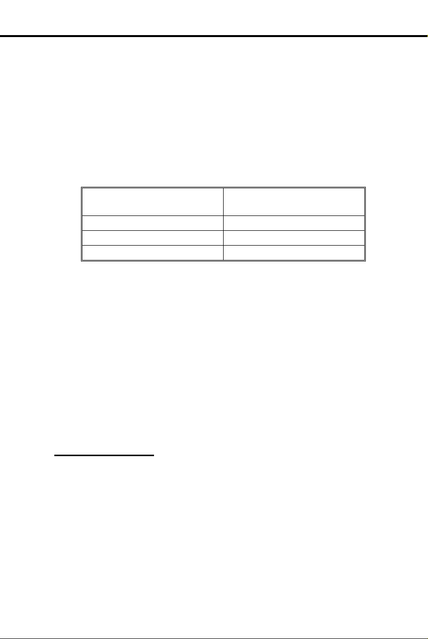
When the DSS/BLF
key is . . .
The extension is . . .
To assign an extension to
a DSS key when your
extension has program
access level 1-5:
Direct Station Selection
Direct Station Selection
Make Intercom calls with two touches. No need to remember, look
✆
up, or dial extension numbers. Your phone can re member a nd dial
them for you.
Direct Station Selection (DSS) lets you call an extension by pressing two keys: ICM,
then the DSS key for the desired extension. Keys 1-15 are the DSS keys. You can
program a DSS ke y t o ca l l whic h ever extension you wish as lon g as yo ur extension
has program a ccess lev el 1-5. You can also use DS S keys to Transfer calls.
In addition, when you press ICM, the DSS keys show you the status of their
associated extensions (the status is called Busy Lamp Field [BLF] and is describ ed
below).
Off Idle
On Busy or ringing
Flashing fast in Do Not Disturb
Direct Station Selection also does the following:
Signals a busy e xt e ns i o n if i t is programmed for Off-Hook Signalin g (s e e pa ge
•
126).
Lets you manually send Call Waiting beeps (see page 55) to a busy extension if
•
it is not programmed for Off-Hook Signaling
Direct Station Selection does not, however, let you contact an extension in Do Not
Disturb unless your extension is programmed for Intrusion (see page 106).
Initial Configuration
DSS/BLF enabled for keys 1-15
•
All DSS keys call extension 300
•
All extensions ca n change DSS exten si on as s ign ments
•
DSS keys automatically activate Off-Hook Signaling (Whisper Page)
•
Intrusion allowed for attendant extension 300
•
Using the Feature
Part I: DIGITAL SYSTEM Features 69
Do not lift handset.
1.
Press #.
2.
Dial DSS. DSS keys flash fast.
3.
Press desired DSS key.
4.
-The key flashes slowly.
Dial extension, press #.
5.
Return to step 4.
6.
OR
Press SAVE to finish.
-All keys go out.
Page 86

To place a call using a
DSS key:
To transfer a call using a
DSS key:
Program 18 (I)
Program 18 (II)
Program 15
Direct Station Selection
Lift handset.
1.
Press ICM.
2.
-If ICM does not light, you do not have DSS keys.
Press lit or unlit DSS key to call the extension.
3.
-If you hear two beeps, spea k.
-If you hear ringing, wait f or an answ er.
-If you hear busy tone, dial C to send Call Waiting
beeps.
-If you hear fast busy, dial I to intrude (override
DND).
Press ICM.
1.
-This puts your call on Hold. If ICM does not light,
you do not have DSS keys.
Press lit or unlit DSS key to call the extension.
2.
-See step 3 above for your options.
Announce the call and hang up.
3.
OR
Hang up to have the call wait at your partner’s extension unannounced.
-If the person does not pick up the Transfer, it recalls
your phone like a normal Tr ansfer.
Understanding Related Programming
To enable/disable DSS capability on keys 1-15 (BLF + #
+ Y or N + #)
To assign extensions to the DSS keys after you enable
them in Program 18 [I] (DSS + # + Key + Extension
number + #)
To assign a program access level to an extension (PGM
ACC LEVEL = 00-05 + #)
70 DIGITAL SYSTEM Administrator’s Guide
Page 87

To answer a call that is
ringing another extension:
Program 16
Directed Call Pickup
Directed Call Pickup
Answer someone else’s call from your phone as long as you know
✆
their extension number.
Directed Call Pickup lets you answer, from your extension, a call that is ringing a
co-worker’s extension. You must, however, know the number of the ringing
extension.
Directed Call Pickup does not answer calls ringing another extension’s Call
Coverage keys.
Initial Configuration
Directed Call Pickup always allowed
Using the Feature
Lift handset.
1.
-If you have a One-Touch Speed Dial key, you can
press it instead of using steps 2-4.
Press ICM (except at an ESL set).
2.
-You hear dial tone.
Dial *.
3.
-Dial tone stops.
Dial number of ringing extension.
4.
-This procedure picks up calls other than calls
ringing other extensions. The pick-up order is as
follows:
Ringing Intercom calls
Personal P a r k calls
Ringing outside calls and Direct Inward Lines
Calls on Hold
Understanding Related Programming
Part I: DIGITAL SYSTEM Features 71
To give an extension access to any line it should be able to
pick up (L + Line 01-16 + # + 02 + #)
Page 88

To place a call using
Directory Dialing:
Directory Dialing
Directory Dialing
Place Intercom or Speed Dial calls by displaying the name of the
✆
person you want to call — the DIGITAL SYSTEM does the rest for
you. No need to refer to a list of Intercom and Speed Dial numbers
filed away at your desk.
If you have a Display Phone, Directory Dialing lets you make an Intercom or Speed
Dial call by name instead of by number. It works like this:
You display the name of the perso n yo u want to call from a stor ed directory
•
("phone book")
Press a button to have the system dial the person’s number
•
Intercom Directory Dialing is always available if the system administrator has stored
extension names in memory.
Speed Dial Directory Dialing is available only if your system is equipped with an
AUX Modu l e. If so , yo u ca n s t or e names with your Person al S pe ed Dia l numbers as
long as your ext e ns i o n has program acc es s l evel 1-5. If you r extension has program
access level 4-5, you can store 100 System Speed Dial names. To store Speed Dial
names from your phone, see Speed Dial on pag e 16 2. Optionally, the system
administrator can store Speed Dial names from a terminal connected to the AUX
Module.
Initial Configuration
Directory Dialing always allowed at Display Phones, but no names are stored initially
Using the Feature
Lift handset.
1.
Dial code (I, P, or C) for names.
2.
-I = Intercom names
-P = P ersonal Speed Di al names
-C = System (Company-Wide) Speed Dial names.
-To scroll through the directory, go to step 5.
-If you see, NO RAM INSTALLED, this means only
Intercom Directory Dialing is available.
Dial first letter of the desired name.
3.
-For example, to dial G: Dial 4. To dial a blank, Q
or Z: Dial 0 (zero).
-After you dial G, for example, the display shows:
1=G, 2=H, 3=I. "1=G" because G is the first letter
on the 4 button, etc.
Dial the number (1, 2, or 3) that corresponds to the let-
4.
ter you just dialed.
-The display shows you the first name stored for that
letter. If you see UNLISTED NAME, this means
there are no stored names for that letter.
Press VOL UP or VOL DN to scroll through the direc-
5.
tory until you see the name you want.
-To begin scrolling from the first name again, dial #.
72 DIGITAL SYSTEM Administrator’s Guide
Page 89

Press DIAL to have the system dial your call.
To exit Directory Dialing
at any time:
Program 14
Program 18 (I)
Program 18 (II)
Program 15
6.
Hang up.
1.
Understanding Related Programming
To assign a name to an extension for Intercom Directory
Dialing (see extension name programming on page 242)
To assign a Spe e d Dial block to an extensio n (SDB + # +
01-28 + #). Names cannot be stored at ex t en s ion s with
blocks 51-57. Remember: Speed Dial names can be
stored only if the system has an AUX card.
To store Speed Dial numbers and names (SD + # + Bin or
key + # + Line name [refer to line name programming on
page 230] + Number + #)
To assign program access level 1-5 (PGM A CC LEVEL
= 01-05 + #) to extens i o ns so t hey can store thei r own
Personal Speed Dial numbers and names
To assign program access level 4-5 (PGM A CC LEVEL
= 04-05 + #) to any extension that should be able to store
System Speed Dial names
Directory Dialing
Part I: DIGITAL SYSTEM Features 73
Page 90

To activate DND for your
extension:
To cancel DND at your
extension:
Program 18 (I)
Do Not Disturb
Do Not Disturb
Work uninterrupted by phone calls when you have paper wo rk to
✆
do.
Do Not Disturb (DND) lets you block incoming pages, ring ing , an d In ter co m voice
announcements. While in DND, you can still use your extension to process calls and
use features. Incoming outside calls still flash the Line keys and you can answer
them, if you wish.
Someone using Hotline (at a phone or DSS Console) or Intrusion, can however,
override your DND and ge t thro ug h. Li k ewise, you can use these fea tures to contact
an extension in DND.
Notes:
Attendants cannot use Do Not Disturb
•
Extension Hunting considers an extension in DND to be busy. This may disrupt
•
normal hunting.
Initial Configuration
Do Not Disturb enabled
Using the Feature
DND is not available to the attendant, even if the attendant is programmed for it.
Pressing the DND key at an attendant extension puts the system in the Night Answer
mode.
Do not lift handset.
1.
Press DND until it flashes.
2.
Activatin g DND does the following at your extension:
-Turns off Background Music, if it was on
-Cancels any Call Forwards
-Makes your extension appear busy if it is a Hunt
Group member
The attendant can automatically canc el a DND condition
at your extension by making it an Alternate Attendant or
by canceling system-wide.
Do not lift handset.
1.
Press DND until it goes out.
2.
Understanding Related Programming
To allow/deny Do Not Disturb for an extension (DND + #
+ Y or N + #)
74 DIGITAL SYSTEM Administrator’s Guide
Page 91

To use the Door Bo
x
:
Door Box
Door Box
From a Door Box installed at an entrance door, a visitor can press
✆
the call button (like a door bell) to ring your phone.
The Door Box (P/N 88545) is a
self-contained Intercom unit
typically used to monitor an
entrance door. A visitor at the do or
can press the Door Box call button
(like a door bell). The Door Box
then sends chime tones to all
extensions programmed to receive
chimes. To answer the chime, the
called extension user just lifts the
handset. This lets the user talk to
the visitor at the Door Box. The
Door Box is convenient to have at a delivery entrance, for example. It is not
necessary to have a co-worker monitor the delivery entrance; they just answer the
Door Box chimes instead.
The system can have up to four Door Boxes (numbered 1-4), installed at extensions
310, 311, 322 and 32 3 in t he Main CEU. Each Door Box has a distinctive chim e
pattern.
Relay Box
The Relay Box (P/N 88546) provides relay contacts for up to four Door Box
locations. A relay typically enables an electric strike on an entrance door next to a
Door Box. After ans wering the Door Bo x c hi m es , you can press a dial pad key to
enable the relay which releases the door. The visitor at the door can then enter
without you having to open the entrance door for them.
You can only install a Relay Box at extension 309 in the Main CEU. This provides
relays for the Door Boxes at extensions 311, 322 and 323. The Relay Box has a
normally open (NO) and normally closed (NC) contact for each Door Box. The relay
for the Door Box at extension 310 is currently unavailable.
Notes:
•
•
Initial Configuration
•
•
Using the Feature
Part I: DIGITAL SYSTEM Features 75
The Door Box is a weather-tight unit, with an operating temperature range of
o
20
C to 60oC (-4oF to 140oF). It is not, however, intended for an outdoor installation directly exposed to the elements (e.g. rain or sunlight).
You can only use a Door Box with software AUX Module Y2.0/Base Y5.0 or
higher.
No Door Boxes installed
Relay Box not installed.
Press and release the Door Box button.
1.
Page 92

To answer the Door Box
chimes (from your
phone):
To call the Door Box
(from your ph one):
Program 17
Program 18 (I)
Door Box
Lift handset.
1.
-If you have a Hotline or Call Coverage key, it will
flash. Press the ke y to answer the Door Box.
Lift handset.
1.
Press ICM (except at ESL set) and dial Door Box ex-
2.
tension number.
-If the Door Box is idle, your call connects. You
don’t hear any tones or ringing before you go
through.
-If you have a Hotline or Call Coverage key, you can
press it to call the Door Box.
(Optional) Release the door strike.
3.
At multibutton set:
Press and hold FTR to release the door.
OR
At ESL set
Dial * (but do not hold it down).
-At a multibutton set, the relay activates as long as
you hold down the FTR key (up to 60 seconds).
-At an ESL set, the relay activates for six seconds
and then automatically releases.
-You can have Relay Boxes for the Door Boxes at
exten s ions 311, 322 and 323 on l y.
Hang up.
4.
Understanding Related Programming
To assign which extensions should have Hotline (Key +
HL + Door Box extension number + #) or Call Coverage
(CCK + Door Box extension number) keys for Door
Boxes.
To assign each Door Box Class of Service 28
(COS + # + 28 + #).
Also, to assign which extensions should receive chime
tones from which Door Boxes (DB + # + DOOR ALERT
= Y or N + # for ea ch Do or B ox).
76 DIGITAL SYSTEM Administrator’s Guide
Page 93

To convert to tone dialing
when using a pulse line:
Program 10
Program 4
DP and DTMF Compatibility
DP and DTMF Compatibility
Any combination of DP and DTMF Central Office lines can be
✆
connected to the DIGITAL SYSTEM.
With Pulse to Tone Conversion, use your pulse (rotary) lines to
access computer services that require tone dialing (such as
banking, MCI, Sprint, etc.).
You can program the system for either DP or DTMF lines from the Central Office.
Pulse to T one Co n ver sion
Pulse to Tone Conversion lets you dial digits on a Dial Pulse (rotary) line, then
convert to tone dialing. After you dial the pulse digits, you simply stop dialing for
six seconds. Any digits you dial after the six-second pause will be dialed out as
tones. When you hang up the call, the dialing mode automatically reverts to pulse.
Initial Configuration
All Lines are CO Loop Start DTMF
Pulse to Tone Conversion enabled
Using the Feature
Place call on pulse line and wait six seconds.
1.
Dial more digits.
2.
-If you call a Speed Di al number that contains a
pulse line and a pause, the system automatically
dials tone digits after the pause.
Understanding Related Programming
To set the dialing mode of a line
Part I: DIGITAL SYSTEM Features 77
To identify the type of line (CIRCUIT TYPE = 10 + #
for CO loop start DTMF, CIRCUIT TYPE = 11 + # for
CO loop start DP) connected to a line port
To set the Make (Timer 10 + # + Duration + #), Break
(Timer 11 + # + Duration + #), and Interdigit timers
(Timer 12 + # + Duration + #) for DP lines
To set the Line Response timer (Timer 04 + # + Duration
+ #) for DP and DTMF lines
Page 94

Program 6
Program 1
Program 18 (I)
Program 10
Program 16
DP and DTMF Compatibility
To set up Pulse to Tone Conversion
To make sure the Active Dialpad option is enabled (ACT
DIAL P AD = Y) in a Toll Restriction level so a use r ca n
continue dialing after a pause; otherwise, Pulse to T one
Conv e r si o n wo ul d be dis abled (see also Pr ogram 1)
To assign a Toll Restriction level (TOLL RESTRICT =
01-07) from Program 6 to a Class of Service (see also
Program 18 [I])
To assign a Class of Service from Program 1 (COS =
01-27 + #) to an extension
To identify a line as a pulse line (11 = CO loop start DP +
#)
To give an extension outgoing access to a line (L + Line
01-16 + # + 02 + #)
78 DIGITAL SYSTEM Administrator’s Guide
Page 95

To use Equal Access
Dialing:
Program 6
Program 1
Program 18 (I)
Equal Access Compatibility
Equal Access Compatibility
Use an alternative long distance service without dialing its
✆
telephone number.
If the DIGITAL SYSTEM is installed in an Equal Access area, you can dial a code to
access a long distance carrier other than your main one (i.e., the one you access when
you dial 1). The code is in the form 10XXX, where XXX is the c ar rier’ s
identification code. The identification code is set up by the local telephone company.
In software A UX Module Y2.0/Base Y5.0 or later, the system does not restrict Equal
Access codes. However, it restricts the phone number according to T oll Restric tion.
In software versions prior to A UX Module Y2.0/Base Y5.0, once you manually dial
an Equal Access code, you can dial any number (i.e., you have unrestricted dialing)
unless your phone has any of the following options enabled in its Class of Service:
Only Intercom Call at Night, which prevents Equal Access dialing during the
•
Night Answer mode.
Only Local Calls at Night, which prevents Equal Access dialing to long dis-
•
tances numbers d uri ng the Ni gh t An s wer mode.
Only Local Calls (Day or Night), which prevents Equal Access dialing to long
•
distance numbers.
The system never restricts an Equal Access call that is stored in System Speed Dial bin.
Initial Configuration
Equal Access Dialing allowed (if the system is in a n Equal Ac ce ss a re a)
Using the Feature
Understanding Related Programming
Part I: DIGITAL SYSTEM Features 79
Access an outside line.
1.
-See Placing an Outside Call on page 134.
Dial Equal Access code.
2.
Dial number.
3.
(Versions prior to AUX Module Y2.0/Base Y5.0)
To allow/deny Equal Access Dialing (EQUAL A CCESS
= Y or N + #). See also Program 1. W ith AUX Module
terminal programming (AP command), you can
allow/deny specific 10XXX codes.
To assign a Toll Level from Program 6 (TOLL
RESTRICT = 01-07 + #) to a Class of Service (see also
Program 18 [I])
To limit Equal Access Dialing using Class of Service
dialing options (see the explanation above)
To assign a Class of Service (COS + #+ 01-27 + #) from
Program 1 to an extension
Page 96

Program 1
Program 18 (I)
Extended Ringing
Extended Ringing
Calls can ring longer than usual to assist people who can’t readily
✆
get to their phones (like a war e hous e w or k er, for ex am pl e).
Extended Ringing forces an unanswered call to ring an extension 15 times before the
system can rero ute it to another exte ns i o n. F or example, a Transfer woul d rin g an
extension 15 times before recalling the extension that transferred it.
If an extension has Extended Ringing, the following types of calls ring it 15 times
before being rerouted:
A Hunting call
•
A Transfer
•
A recalling call on Hold
•
A ring-no-answer forwarded call
•
A Direct Inward Line
•
A Direct Inward Dialing call
•
Initial Configuration
Extended Rin gi n g di s abled
Using the Feature
N/A
Understanding Related Programming
Note: Enabling Extended Ringing overrides Timer 06 (Number of Rings Before
Recall).
To enable/disable Extended Ringing in a Class of Service
(EXTENDED RING = Y or N + #). See al s o P r og ram 18
(I).
To assign a Class of Service (COS + # + 01-27 #) from
Program 1 to an extension
80 DIGITAL SYSTEM Administrator’s Guide
Page 97

Extension Hunting
Extension Hunting
Call handling among people in a sales or service department
✆
becomes very efficient. If one per so n is busy handling a custom er,
the DIGITAL SYSTEM sends a new call to another person in the
group. No need for an attendant to look for an available person to
take a call.
Extension Hunting sends a call through a group of extensions until it is answered. In
other words, if a call tries a Hunt Group extension and it is busy, the call tries (hunts
for) the next available extension in the group, and so on.
The following types of calls hunt when they come into a Hunt Group extension:
Ringing Intercom calls
•
Transferred calls
•
Direct Inward Lines
•
DISA calls
•
Voice-announced Intercom calls and lines assigned to a Hunt Group extension
through Program 16 do not hunt.
A Hunt Group can have any number of members, and the system can have any
number of Hunt Groups. However, an extension can be in only one Hunt Group.
There are three types of Extension Hunting:
Circular Hunting
A Circular Hunt Group consists of extensions programmed into an ordered "circular"
list, where the first and last extension are the same (e.g., 304, 305, 306, 307, 304). If
a call is unanswered at one extension, it moves to the next extension in the list. If
still unanswered, it rings all remaining members, circling back to the top of the list if
necessary. If not picked up after ringing all group members:
An Intercom call continues to ring the last extension in the group
•
An outside call rings all extensions programmed for ringing on that line (an un-
•
answered Transfer call may recall the transferer before ringing the other extensions)
Terminal Hunting
A T e rmina l Hunt Group consists of extensions programmed into a ordered list (e.g.,
304, 305, 306, 307). If a call is unanswered at one extension, it moves to the next
extension in the list. If still unanswered, it rings the remaining members until it
reaches the bottom of the list; it does not circle back to the top of the list. If still
unanswered:
An Intercom call continues to ring the last extension in the group
•
An outside call can ring the attendant or all extensions programmed for ringing
•
on that line (an unanswered Transfer may recall the transferer before ringing the
other extensions)
Part I: DIGITAL SYSTEM Features 81
Page 98

Extension Hunting
Uniform Call Distribution (UCD)
A UCD Hunt Group consists of extensions programmed into a list, and the group is
assigned a master extension number. The UCD Hunting process begins when a cal l
comes into the master extension number (such as a call transferred t o the master number).
The order in which the call rings the member extensions depends on ho w b usy the
extensions have been. The f irs t ext ension rung is the one t hat has been idle the longes t.
The last extension rung is the one that has been bus iest. If all UCD members are b usy, the
call waits (Camps-On) for the programmed Camp-On time, then moves to the ov erflo w
extension (if any). If not answered at the ov erflo w ext ension, a waiting out side call rings
all extensions programmed for ringing on that line.
Notes:
Hunt Groups can be linked together. For example, a UCD master number ca n be
•
the last member of a Terminal Hunt Group, or the overflow f or an other UCD
Hunt Group.
Activating at a Hunt Group extension disrupts normal hunting.
•
Activating DND at a Hunt Group extension temporarily removes it from the
•
group. If a "Circular" extension is in DND, an outside call continua lly cycles
through the group.
Two attendants (e.g., 307, 304 ) ca n be in a circular Hunt Group for special Night
•
Answer operation (the group = 307, 304, 307 with type 02). Both attendan ts
must activate Night Answer to put their lines into the Night Answer mode.
Automatic Call Distribution is similar to UCD Hunting, but with unique supervi-
•
sor and agent features. Refer to page 36 for the specifics.
Extension Hunting considers an extension in DND to be busy. This may disrupt
•
normal hunting.
Initial Configuration
Extension Hunting disabled (No Hunt Groups assigned)
Using the Feature
N/A
82 DIGITAL SYSTEM Administrator’s Guide
Page 99

Understanding Related Programming
Program 19
Program 4
Program 17
Program 12
Program 18 (II)
To set up Hunt Groups (see page 272)
T o s et two timers: Camp-On (T imer 03 + # + Duration + # –
how long a call waits at a busy UCD group) and Rings
Before Recall (Timer 06 + # + Duration + # – the number of
times a call rings a Hunt Group extension before going to the
next one; and, before ringing all extensions with ringing and
access for that line)
To assign a Call Coverage (CCK + Master extension
number + #) or Hotline (HL + Master extension number
+ #) key for a UCD master number (k ey lights when all
members are busy)
To directly terminate a line to a UCD master number
(DTD or DTN + # + master number + #) so calls ring it
instead of having to be transferred to it
To disable Whisper Page (VO + # + Y or N + #) for
extensions in Circular and Terminal Hunt Groups
Extension Hunting
Part I: DIGITAL SYSTEM Features 83
Page 100

Program 7
Program 16
External Alerting Device
External Alerting Device
The ringing for incoming calls is amplified so it can be heard in
✆
large noisy areas, such as a machine shop.
An External Alerting Device, such as a bell, can be connected to Relay 01 (located in
the Main CEU) and Relay 02 (located in Expansion CEU #1). You can program the
system so that a relay activates and the bell rings when an incoming call rings one of
the following destinations:
A line (348-363)
•
An extension (300-347)
•
A Ring Group (3 64 -3 71 wit h ou t AUX, 396-403 with AUX)
•
The relay activates for day and Night Answer calls with one exception: If you select
extension 300 for a relay, the relay activates only for calls that ring extension 300
while it is in the Night Answer mode. You can also program the relays to have a
steady or inte rr up t ed cl o s ur e, depending on wha t t he Ex t er nal Alerting De v ice
requires.
An External Alerting Device must be compatible with the following relay
specifications:
Maximum Load 60 mA @ 30 Vdc
10 mA @ 90 Vdc
Initial Configuration
Relays 01 and 02 activate when a call rings extension 300 durin g the Night
•
mode
Relays 01 and 02 are pr ogrammed for steady closure
•
Using the Feature
See Answerin g an Outside Cal l on page 132 or Ni gh t An s w er on page 121.
Understanding Related Programming
To select the type of call that activa tes a re lay ( RELAYnn
OWNER = line, extension or Ring Group + #)
To select interrupted or steady closure for the relays
(INTRUP RING RLY = Y or N + #)
To give an extension access to the line you assign to a
relay so the extension can answer a call on that line (L +
Line 01-16 + # + 01 or 02 + #)
84 DIGITAL SYSTEM Administrator’s Guide
 Loading...