

Page 1

NEC Express5800/BladeServer Series
N8400-083F/084F/085F
NEC Express5800/B120a
User's Guide
1st Edition
2-2009
ONL-540_001_04-B120a-100-99-0902
Page 2

PROPRIETARY NOTICE AND LIABILITY DISCLAIMER
The information disclosed in this document, including all designs and related materials, is the
valuable property of NEC Corporation (NEC) and /or its licensors. NEC and/or its licensors, as
appropriate, reserve all patent, copyright and other proprietary rights to this document, including all
design, manufacturing, reproduction, use, and sales rights thereto, except to the extent said rights are
expressly granted to others.
The NEC product(s) discussed in this document are warranted in accordance with the terms of the
Warranty Statement accompanying each product. However, actual performance of each such
product is dependent upon factors such as system configuration, customer data, and operator control.
Since implementation by customers of each product may vary, the suitability of specific product
configurations and applications must be determined by the customer and is not warranted by NEC.
To allow for design and specification improvements, the information in this document is subject to
change at any time, without notice. Reproduction of this document or portions thereof without prior
written approval of NEC is prohibited.
First Printing, February 2009
Copyright 2009
NEC Corporation
7-1 Shiba 5-Chome, Minato-Ku
Tokyo 108-8001, Japan
All Rights Reserved
Printed in Japan
Page 3
Keep this User's Guide at hand for quick reference at anytime necessary.
SAFETY INDICATIONS
Follow the instructions in this User's Guide for your safety to use the server.
The server contains components with possible danger, hazards that may cause by ignoring warnings,
and preventive actions against such hazards.
Server components with possible danger are indicated with a warning label placed on or around them
as well as described in this User's Guide.
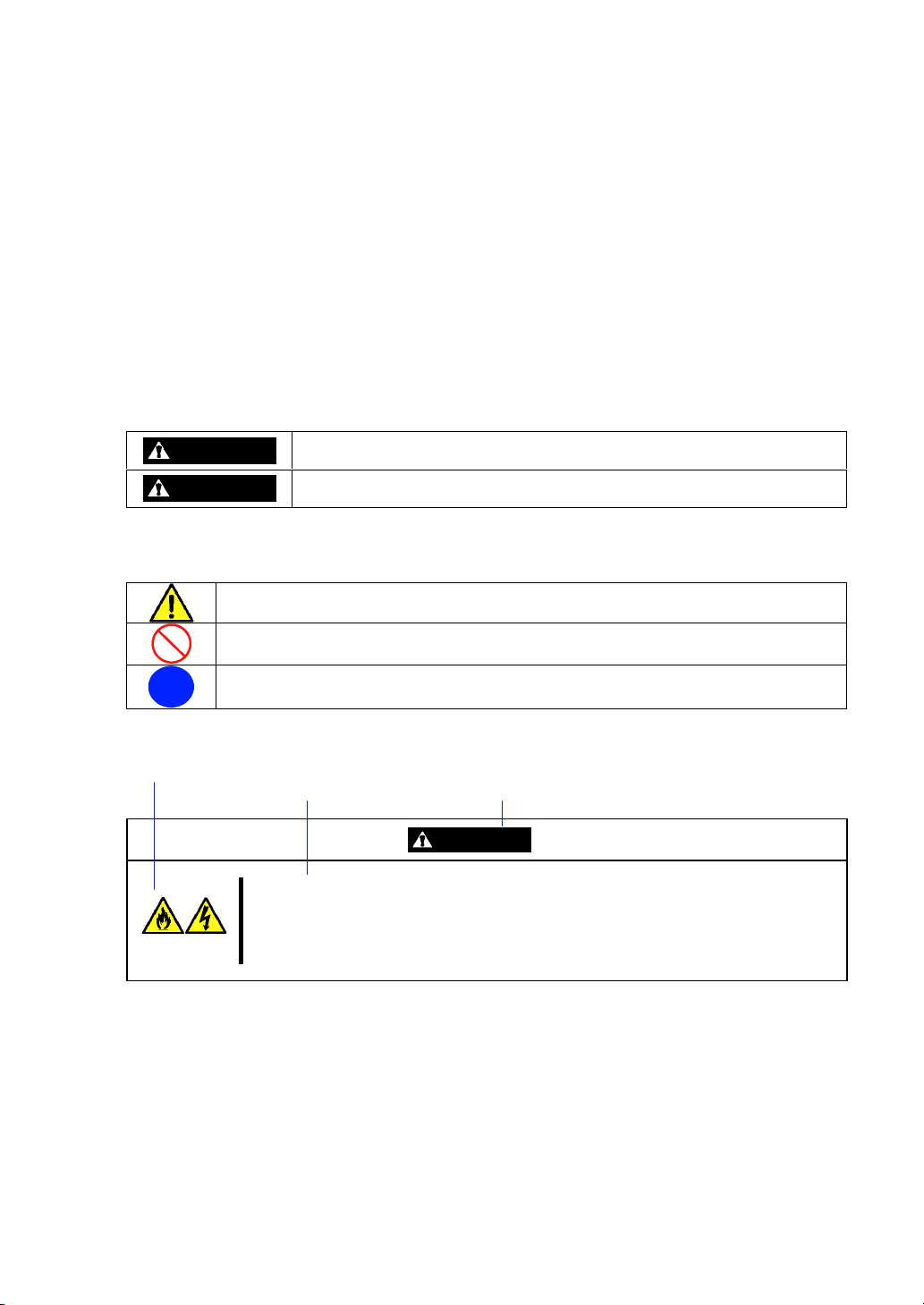
In the User's Guide or warning labels, "WARNING" or "CAUTION" is used to indicate a degree of
danger. These terms are defined as follows:
WARNING
CAUTION
Precautions and notices against hazards are presented with one of the following three symbols. The
individual symbols are defined as follows:
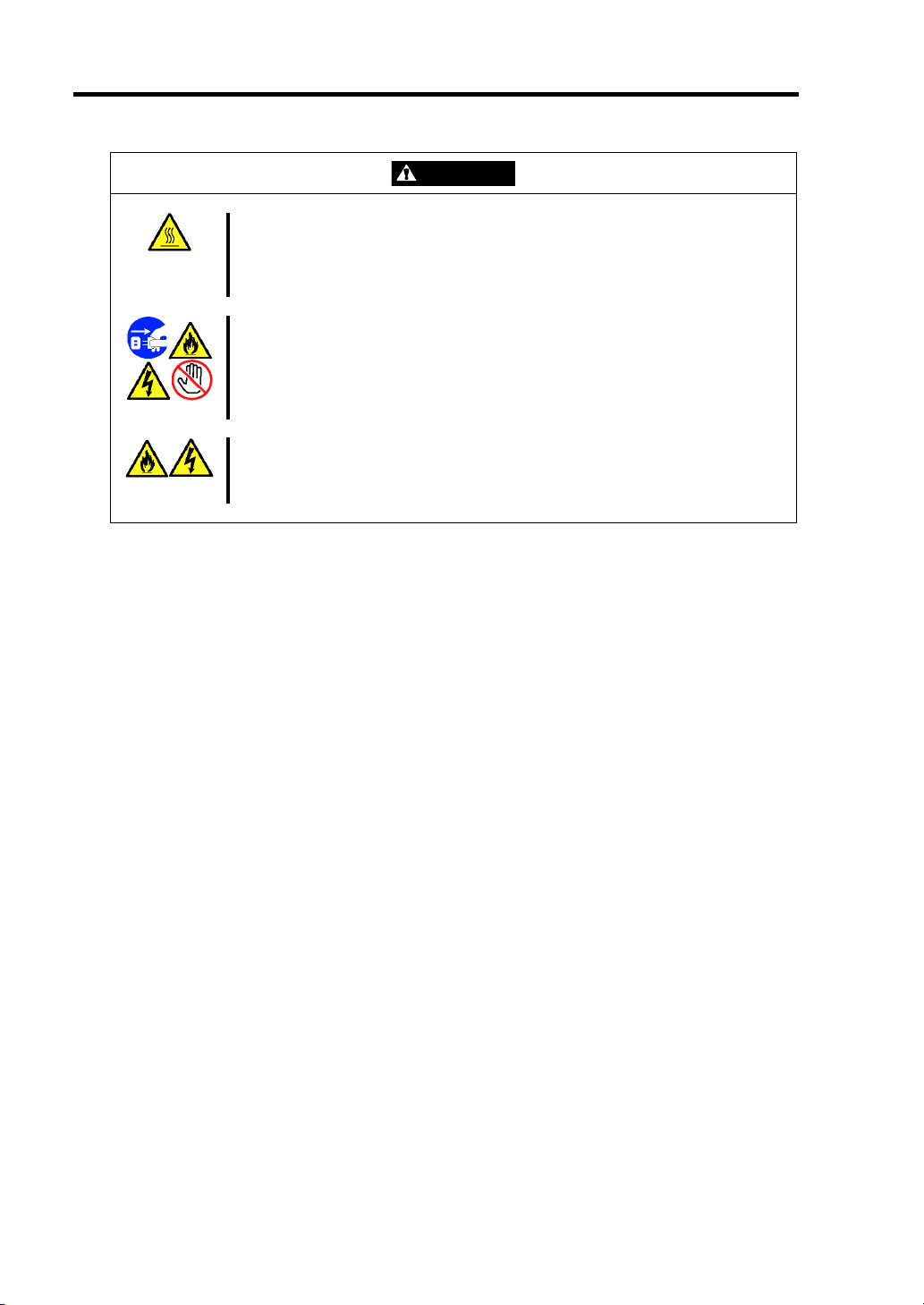
This symbol indicates the presence of a hazard if the instruction is ignored.
An image in the symbol illustrates the hazard type. (Attention)
This symbol indicates prohibited actions. An image in the symbol illustrates a particular
prohibited action. (Prohibited Action)
This symbol indicates mandatory actions. An image in the symbol illustrates a
mandatory action to avoid a particular hazard. (Mandatory Action)
(Example)
(Example)
Symbol to draw attention
Indicates the presence of a hazard that may result in death or serious
personal injury if the instruction is ignored.
Indicates the presence of a hazard that may cause minor personal injury,
including burns, or property damage if the instruction is ignored.
Description of a danger Term indicating a degree of danger
CAUTION
Plug in to a proper power source.
Use a proper wall outlet. Use of an improper power source may cause a fire or a
power leak.
Page 4
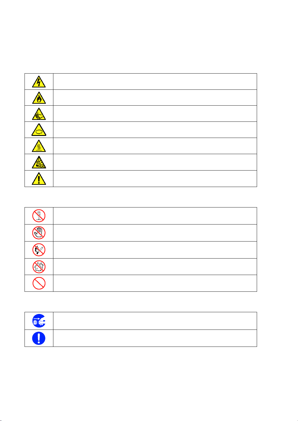
Symbols used in this User's Guide and warning labels are listed below.
Attentions
Indicates that improper use may cause an electric shock.
Indicates that improper use may cause fumes or fire.
Indicates that improper use may cause fingers to be caught.
Indicates that improper use may cause personal injury by the moving fan blades.
Indicates that improper use may cause personal injury.
Indicates that improper use may cause explosion.
Indicates a general notice or warning that cannot be specifically identified.
Prohibited Actions
Do not disassemble, repair, or modify the server. Otherwise, an electric shock or fire
may be caused.
Do not touch any component other than specified. Otherwise, an electric shock or
personal injury such as burns may be caused.
Keep away from fire. Otherwise, an ignition may be caused.
Keep away from water or liquid. Otherwise, an electric shock or fire may be caused.
Indicates a general prohibited action that cannot be specifically identified.
Mandatory Action
Unplug the power cord of the server. Otherwise, an electric shock or fire may be
caused.
Indicates a mandatory action that cannot be specifically identified. Make sure to follow
the instruction.
Page 5

NOTE: This equipment has been tested and found to comply with the limits for a Class A digital
device, pursuant to Part 15 of the FCC Rules. These limits are designed to provide reasonable
protection against harmful interference when the equipment is operated in a commercial
environment. This equipment generates, uses, and can radiate radio frequency energy and, if not
installed and used in accordance with the instruction manual, may cause harmful interference to
radio communications. Operation of this equipment in a residential area is likely to cause harmful
interference in which case the user will be required to correct the interference at his own expense.
BSMI Statement (N8400-083F/084F/085F)
CE Mark EMI:
Australia EMI:
NOTE: This is a Class A product. In domestic environment, this product may cause radio
interference in which case the user may be required to take adequate measures.
Canada EMI:
This Class A digital apparatus meets all requirements of the Canadian Interference-Causing
Equipment Regulations.
Cet appareil numérique de la classe A respecte toutes les exigences du Règlement sur le matériel
brouilleur du Canada.
Page 6

Trademarks
NEC ESMPRO and NEC EXPRESSBUILDER are trademarks of NEC Corporation.
Microsoft, Windows, Windows Server, Windows NT, and MS-DOS are registered trademarks or trademarks of Microsoft
Corporation in the United States and other countries.
Intel and Pentium are registered trademarks of Intel Corporation.
Datalight is a registered trademark of Datalight, Inc.
ROM-DOS is a trademark of Datalight, Inc.
AT is a registered trademark of International Business Machines Corporation in the United States and other countries.
LSI and the LSI logo design are trademarks or registered trademarks of LSI Corporation.
Adaptec and its logo is a registered trademark of Adaptec, Inc. of United States.
SCSISelect is a trademark of Adaptec, Inc. of the United States.
Adobe, Adobe logo, and Acrobat are trademarks of Adobe Systems Incorporated.
All other product, brand, or trade names used in this publication are the trademarks or registered trademarks of their
respective trademark owners.
Windows Server 2008 stands for Microsoft® Windows Server® 2008 Standard Operating system and Microsoft® Windows
Server® 2008 Enterprise operating system. Windows Server 2003 x64 Editions stands for Microsoft® Windows Server
2003 R2, Standard x64 Edition operating system and Microsoft® Windows Server® 2003 R2, Enterprise x64 Edition
operating system, or Microsoft® Windows Server® 2003, Standard x64 Edition operating system and Microsoft® Windows
Server® 2003, Enterprise x64 Edition operating system. Windows Server 2003 stands for Microsoft® Windows Server
2003 R2, Standard Edition operating system and Microsoft® Windows Server® 2003 R2, Enterprise Edition operating
system, or Microsoft® Windows Server® 2003, Standard Edition operating system and Microsoft® Windows Server® 2003,
Enterprise Edition operating system. Windows XP x64 Edition stands for Microsoft® Windows® XP Professional x64
Edition operating system. Windows XP stands for Microsoft® Windows® XP Home Edition operating system and
Microsoft® Windows® XP Professional operating system. Windows 2000 stands for Microsoft® Windows® 2000 Server
operating system and Microsoft® Windows® 2000 Advanced Server operating system, and Microsoft® Windows® 2000
Professional operating system. Windows NT stands for Microsoft® Windows NT® Server network operating system version
3.51/4.0 and Microsoft® Windows NT® Workstation operating system version 3.51/4.0. Windows Me stands for Microsoft
Windows® Millennium Edition operating system. Windows 98 stands for Microsoft® Windows®98 operating system.
Windows 95 stands for Microsoft® Windows®95 operating system. WinPE stands for Microsoft® Windows® Preinstallation
Environment.
®
®
®
Momentary voltage drop prevention:
This product may be affected by a momentary voltage drop caused by lightning. To prevent a
momentary voltage drop, an AC uninterruptible power supply (UPS) unit should be used.
Notes:
(1) No part of this manual may be reproduced in any form without the prior written permission of
NEC Corporation.
(2) The contents of this User's Guide may be revised without prior notice.
(3) The contents of this User's Guide shall not be copied or altered without the prior written
permission of NEC Corporation.
(4) All efforts have been made to ensure the accuracy of all information in this User's Guide. If
you notice any part unclear, incorrect, or omitted in this User's Guide, contact the service
representative where you purchased this product.
(5) NEC assumes no liability arising from the use of this product, nor any liability for incidental or
consequential damages arising from the use of this User's Guide regardless of Item (4).
Page 7

PREFACE
Welcome to the NEC Express5800/BladeServer series server.
The NEC Express5800/BladeServer holds powerful performance and employs the latest technology
to implement a computer for the next generation. With its potential capabilities, the server may be
used as the workstation PC that configures a client-server system and provides high-speed
processing and superior reliability.
Read this User's Guide thoroughly to fully understand handling of the server and appreciate its
functions to the maximum extent.
i
Page 8

ii
ABOUT THIS USER'S GUIDE
This User's Guide is a guide for proper setup and use of the server.
This User's Guide also covers useful procedures for dealing with difficulties and problems that may
arise during setup or operation of the server.
Keep this manual for future use.
The following describes how to proceed with this User's Guide.
How to Use This User's Guide
To aid you in finding information quickly, this User's Guide contains the following information:
Chapter 1 Notes on Using Your Server
includes information that needs attention to use the CPU blade. Make sure to read this
chapter before setting up and using the CPU blade. It also includes requirements and
advisory information for transfer and disposal of the CPU blade.
Chapter 2 General Description
includes information necessary to use the CPU blade, such as names and functions of its
components.
Chapter 3 Setting Up Your Server
tells you how to select a site, unpack the system, make cable connections, and power on
your system.
Chapter 4 Configuring Your Server
tells you how to configure the system and provides instructions for running the BIOS Setup
Utility and the LSI Software RAID Configuration Utility, which is used to configure RAID drive
in your system.
Chapter 5 Installing the Operating System
describes how to install the operating system.
Chapter 6 Installing and Using Utilities
describes how to install the utilities for the server. It also includes a description on using the
attached "NEC EXPRESSBUILDER" DVD.
Chapter 7 Maintenance
provides you with all the information necessary to maintain successful operation of the CPU
blade.
Chapter 8 Troubleshooting
contains helpful information for solving problems that might occur with your system.
Chapter 9 Upgrading Your Server
provides you with instructions for upgrading your system with an additional processor,
optional memory, optional mezzanine cards, and hard disk drives.
Appendix A Specification
provides specifications for your CPU blade.
Appendix B Installing the Operating System
describes how to install Microsoft Windows Server 2008, Microsoft Windows Server 2003
x64 Editions, and Windows Server 2003 without using Express Setup.
Page 9

Text Conventions
The following conventions are used throughout this User's Guide. For safety symbols, see
"SAFETY INDICATIONS" provided earlier.
iii
IMPORTANT:
NOTE:
Items that are mandatory or require attention when using the server
Helpful and convenient piece of information
IN THE PACKAGE
The carton contains various accessories, as well as the server itself. See the packing list to make
sure that you have everything and that individual components are not damaged. If you find any
component missing or damaged, contact your service representative.
Store the provided accessories in a designated place for your convenience. You will need
them to install an optional device or troubleshoot the server, as well as to set it up.
Make a backup copy of each provided floppy disk, if any. Store the original disk as the
master disk in a designated place, and use its copy.
Improper use of any provided floppy disk or CD-ROM may alter your system
environment. If you find anything unclear, immediately ask your service representative for
help.
Page 10

iv
CONTENTS
Preface ..............................................................................................................................................i
About This User's Guide..................................................................................................................ii
In the Package................................................................................................................................ iii
Chapter 1 Notes on Using Your Server........................................................................ 1-1
Safety Notes................................................................................................................................. 1-2
For Proper Operation ................................................................................................................... 1-5
Transfer to Third Party................................................................................................................. 1-7
Disposal and Consumables .......................................................................................................... 1-8
User Support ................................................................................................................................ 1-9
Chapter 2 General Description ..................................................................................... 2-1
Overview...................................................................................................................................... 2-2
Standard Features......................................................................................................................... 2-3
Part Names and Controls ............................................................................................................. 2-4
CPU Blade............................................................................................................................... 2-4
Hard Disk Drive ...................................................................................................................... 2-8
Lamp Indications..................................................................................................................... 2-9
Using Your Server...................................................................................................................... 2-15
Power-on of Blade Server...................................................................................................... 2-15
Power-off of Blade Server ..................................................................................................... 2-17
POST ..................................................................................................................................... 2-17
Device Identification ............................................................................................................. 2-20
Chapter 3 Setting Up Your Server ................................................................................3-1
Before Installing CPU Blade ....................................................................................................... 3-2
Check of MAC Address........................................................................................................... 3-2
Installing DIMM...................................................................................................................... 3-2
Installing the CPU Blade ............................................................................................................. 3-3
Installing the Hard Disk Drive..................................................................................................... 3-3
Making Connections .................................................................................................................... 3-4
Network................................................................................................................................... 3-6
Chapter 4 Configuring Your Server.............................................................................. 4-1
System BIOS ~ SETUP ~ ............................................................................................................ 4-1
Starting SETUP Utility ............................................................................................................ 4-2
Description on On-Screen Items and Key Usage .................................................................... 4-3
Menu and Parameter Descriptions........................................................................................... 4-4
Page 11

RAID Configuration ...................................................................................................................4-23
RAID......................................................................................................................................4-23
Configuration by N8403-027 SATA Interface Card ...............................................................4-28
LSI Software Configuration Utility........................................................................................4-29
Menu Tree ..............................................................................................................................4-31
Operating Procedures for Setup Utility ..................................................................................4-32
LSI Software Configuration Utility and Universal RAID Utility...........................................4-39
Configuration by N8403-026 RAID Controller .....................................................................4-41
Before Using WebBIOS .........................................................................................................4-45
Using WebBIOS.....................................................................................................................4-48
Configuring Virtual Drive ......................................................................................................4-62
Operation of Various Features ................................................................................................4-72
Locate.....................................................................................................................................4-81
Slow Initialize ........................................................................................................................4-82
WebBIOS and Universal RAID Utility ..................................................................................4-83
Chapter 5 Installing the Operating System with Express Setup............................... 5-1
About Express Setup ....................................................................................................................5-2
Windows Server 2008...................................................................................................................5-3
Notes on Windows Installation.................................................................................................5-3
Flow of Setup ...........................................................................................................................5-7
Installing the Windows Server 2008.........................................................................................5-8
Installing and Setting Device Drivers.....................................................................................5-21
Microsoft Windows Server 2003................................................................................................5-22
Notes on Windows Installation...............................................................................................5-22
Flow of Setup .........................................................................................................................5-28
Installing the Windows Server 2003.......................................................................................5-29
Installing and Setting Device Drivers.....................................................................................5-38
Available Switch Options for Windows Server 2003 Boot.ini file.........................................5-39
Setting for Solving Problems......................................................................................................5-40
Installing Maintenance Utilities..................................................................................................5-52
Updating the System...................................................................................................................5-52
Making Backup Copies of System Information..........................................................................5-53
Installing with the OEM-FD for Mass Storage Device ..........................................................5-54
v
Chapter 6 Installing and Using Utilities ....................................................................... 6-1
NEC EXPRESSBUILDER...........................................................................................................6-2
Autorun Menu ..........................................................................................................................6-6
Parameter File Creator..................................................................................................................6-7
Parameter File ..........................................................................................................................6-8
NEC ESMPRO ...........................................................................................................................6-20
Universal RAID Utility...............................................................................................................6-22
Setup with Express Setup.......................................................................................................6-22
Manual Setup .........................................................................................................................6-22
Using Universal RAID Utility via Network...........................................................................6-22
Page 12

vi
NEC Product Info Collection Utility.......................................................................................... 6-23
Installation ............................................................................................................................. 6-23
Using Utility .......................................................................................................................... 6-23
Uninstallation ........................................................................................................................ 6-23
Chapter 7 Maintenance.................................................................................................. 7-1
Making Backup Copies................................................................................................................ 7-1
System Diagnostics...................................................................................................................... 7-2
Test Items ................................................................................................................................ 7-2
Startup and Exit of System Diagnostics .................................................................................. 7-3
Chapter 8 Troubleshooting ........................................................................................... 8-1
System Viewers............................................................................................................................ 8-2
Error Messages ............................................................................................................................ 8-3
POST Error Messages .............................................................................................................8-3
Lamps .......................................................................................................................................... 8-7
Solving Problems......................................................................................................................... 8-8
CPU Blade............................................................................................................................... 8-8
Problems with Windows........................................................................................................ 8-14
Problems with NEC EXPRESSBUILDER............................................................................ 8-19
Problems with Express Setup ................................................................................................ 8-20
Problems with Parameter File Creator................................................................................... 8-22
Problem with Disk Array Configuration................................................................................ 8-22
Problems with RAID System and RAID Controller.............................................................. 8-22
Problems with N8403-018 FibreChannel Controller............................................................. 8-23
Collecting Event Log ................................................................................................................. 8-24
Collecting Configuration Information........................................................................................ 8-25
Collecting Dr. Watson Diagnostic Information.......................................................................... 8-25
Memory Dump........................................................................................................................... 8-26
Recovery for Windows System.................................................................................................. 8-27
Maintenance Tools ..................................................................................................................... 8-28
Starting Maintenance Tools ................................................................................................... 8-28
Function of Maintenance Tools ............................................................................................. 8-30
Maintenance Tools with Remote Console ............................................................................. 8-32
Resetting the CPU blade ............................................................................................................ 8-34
Forced Shutdown ....................................................................................................................... 8-35
Chapter 9 Upgrading Your Server ................................................................................9-1
Safety Notes................................................................................................................................. 9-2
Anti-static Measures .................................................................................................................... 9-3
Preparation for Installation .......................................................................................................... 9-4
Installation/Removal Procedure................................................................................................... 9-5
Processor (CPU) ...................................................................................................................... 9-5
DIMM.................................................................................................................................... 9-14
Mezzanine Card..................................................................................................................... 9-20
Interface Card for Connecting Hard Disk Drive.................................................................... 9-26
Hard Disk Drive .................................................................................................................... 9-30
Page 13

vii
Appendix A Specifications............................................................................................A-1
Appendix B Installing the Operating System..............................................................B-1
Setup and Re-setup of CPU Blade of Diskless Model................................................................. B-1
Local Installation..................................................................................................................... B-1
Remote Desktop for Management............................................................................................. B-33
Windows Server 2008 ........................................................................................................... B-33
Windows Server 2003 x64 Editions...................................................................................... B-33
Windows Server 2003 ........................................................................................................... B-34
Setup of Device Driver (Normally Installed in Server)............................................................. B-35
PROSet.................................................................................................................................. B-35
Network Driver .....................................................................................................................B-36
Graphics Accelerator............................................................................................................. B-37
Installing Fibre Channel Controller Driver (N8403-018)...................................................... B-37
Optional Network Board Driver............................................................................................ B-38
Setup of Adapter Fault Tolerance (AFT)/Adaptive Load Balancing (ALB).............................. B-40
Setup Teaming....................................................................................................................... B-41
Remove Team........................................................................................................................ B-43
Setting WOL.............................................................................................................................. B-44
SETTING Receive Side Scaling................................................................................................ B-47
Re-installation of the Network Driver ....................................................................................... B-48
Available Switch Options for Windows Server 2003 Boot.ini File....................................... B-50
Setting for Solving Problems..................................................................................................... B-51
Setting for Collecting Memory Dump (Debug Information) ................................................ B-51
Re-installing the Operation System if Multiple Logical Drives Exist................................... B-51
Updating the System - Applying Service Pack -........................................................................ B-53
Local Update ......................................................................................................................... B-54
Update from TS Client (Windows Server 2008) ................................................................... B-62
Update from TS Client (Windows Server 2003 x64 Editions) .............................................. B-63
Update from TS Client (Windows Server 2003) ................................................................... B-66
About Windows Activation ................................................................................................... B-69
Page 14

viii
(This page is intentionally left blank.)
Page 15

Chapter 1
Notes on Using Your Server
This chapter includes information necessary for proper and safe operation of the server.
Page 16
1-2 Notes on Using Your Server
SAFETY NOTES
This section provides notes on using the server safely. Read this section carefully to ensure proper
and safe use of the server. For symbols, see "SAFETY INDICATIONS" provided earlier.
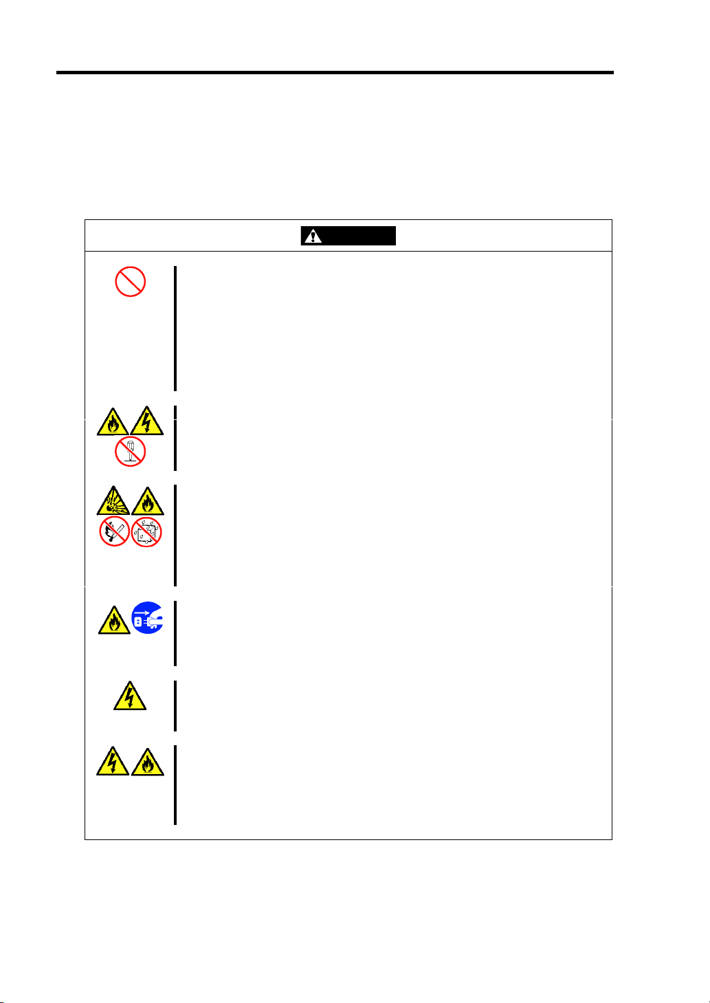
WARNING
Do not use the server for services where critical high availability may directly
affect human lives.
The server is not intended to be used with or control facilities or devices
concerning human lives, including medical devices, nuclear facilities and
devices, aeronautics and space devices, transportation facilities and devices;
and facilities and devices requiring high reliability. NEC assumes no liability
for any accident resulting in personal injury, death, or property damage if the
server has been used in the above conditions.
Do not disassemble, repair, or alter the server.
Never attempt to disassemble, repair, or alter the server on any occasion
other than described in this User's Guide. Failure to follow this instruction may
cause an electric shock or fire as well as malfunctions of the server.
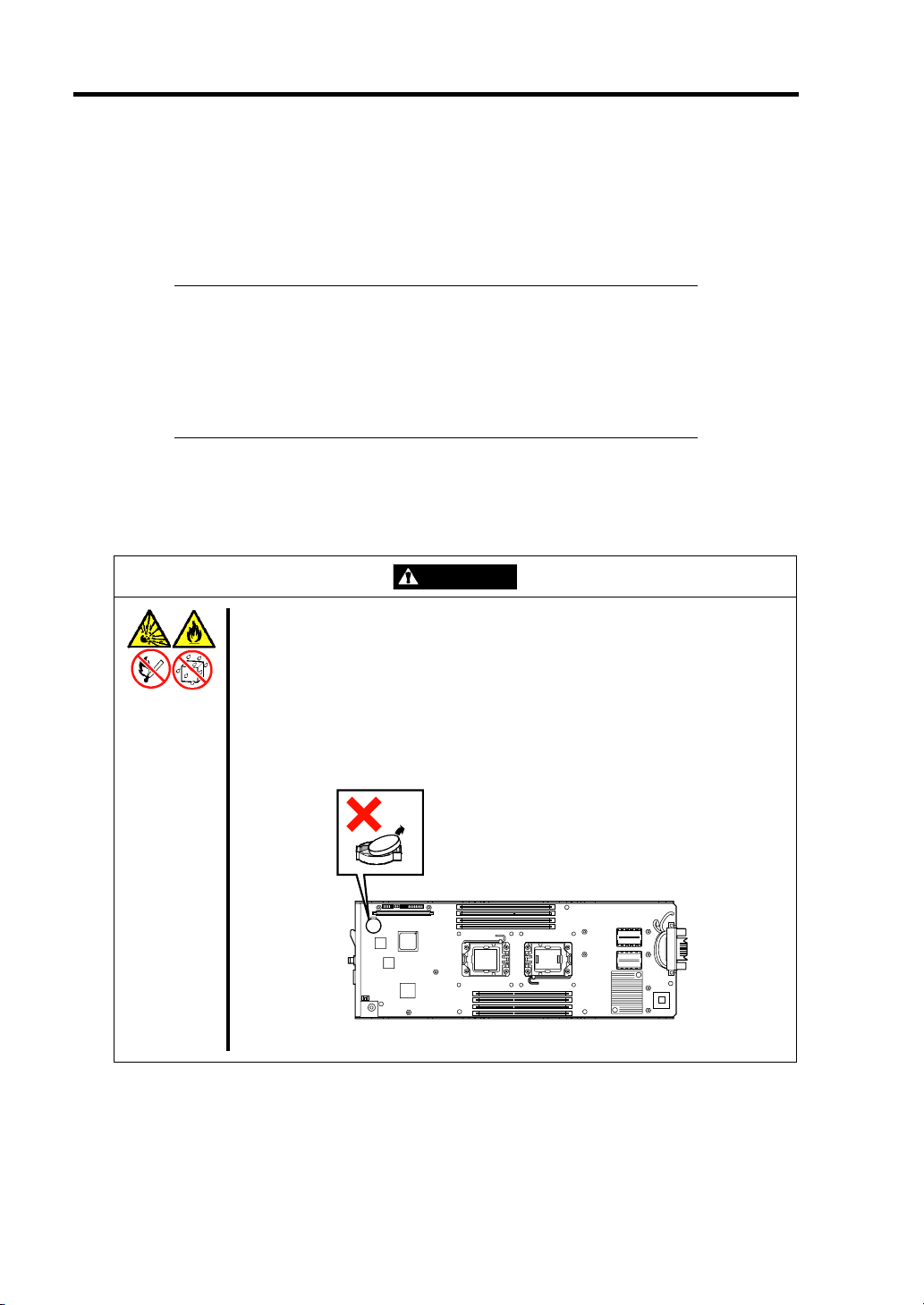
Do not remove the lithium battery.
The server contains the lithium battery. Do not remove the battery. Placing
the lithium close to a fire or in the water may cause an explosion.
When the server does not operate appropriately due to the dead lithium
battery, contact your service representative. Do not disassemble the server to
replace or recharge the battery by yourself.
Do not use the server if any smoke, odor, or noise is present.
If smoke, odor, or noise is present, immediately turn off the system and
disconnect the power plug from the outlet, then contact your service
representative. Using the server in such conditions may cause a fire.
Keep needles or metal objects away from the server.
Do not insert needles or metal objects into ventilation holes in the server.
Doing so may cause an electric shock.
Use the devices only in the specified areas.
CPU blades and hard disk drives should be installed in the dedicated Blade
Enclosure for their uses. Do not install the CPU blades and hard disk drives in
a chassis other than the Blade Enclosure. Failure to follow it may result in fire
and/or electric shock to occur.
Page 17
Notes on Using Your Server 1-3
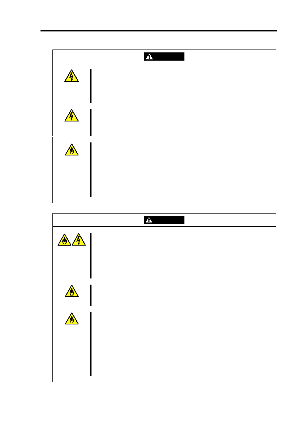
WARNING
Do not handle the CPU blade if it is installed in the Blade Enclosure.
To install or remove an option from the CPU blade, first turn off the power of
the CPU blade and remove the CPU blade from the Blade Enclosure. If you
touch parts on the CPU blade with it connected to the Blade Enclosure, you
may get an electric shock.
Do not install or remove more than one CPU blade at a time.
Install or remove CPU blades one by one. If you install or remove more than
one CPU blade at a time or a CPU blade with the cover of another slot
removed, you may be electrically shocked.
Do not use the equipment in the place where corrosive gases exist.
Make sure not to locate or use the server in the place where corrosive gases
(sulfur dioxide, hydrogen sulfide, nitrogen dioxide, chlorine, ammonia, ozone,
etc) exist.
Also, do not set it in the environment where the air (or dust) includes
components accelerating corrosion (ex. sulfur, sodium chloride) or conductive
metals. There is a risk of a fire due to corrosion and shorts of an internal
printed board.
CAUTION
Keep water or foreign matter away from the CPU blade.
Do not let any form of liquid (water etc.) or foreign matter (e.g., pins or paper
clips) enter the server. Failure to follow this warning may cause an electric
shock, a fire, or a failure of the server. When such things accidentally enter
the server, immediately turn off the power and disconnect the power plug
from the outlet. Do not disassemble the server. Contact your service
representative.
Make sure to complete device installation.
Always install a CPU blade, hard disk drive and board firmly. An incompletely
installed device may cause a contact failure, resulting in smoking or fire.
Do not use any unauthorized interface cable.
Use only interface cables provided by NEC and locate a proper device and
connector before connecting a cable. Using an authorized cable or
connecting a cable to an improper destination may cause a short circuit,
resulting in a fire.
Also, observe the following notes on using and connecting an interface cable.
Do not use any damaged cable connector.
Do not step on the cable.
Do not place any object on the cable.
Do not use the Blade Enclosure with loose cable connections.
Page 18
1-4 Notes on Using Your Server
Avoid installation in extreme temperature conditions.
Immediately after the server is powered off, its internal components such as
hard disk drives are very hot. Leave the server until its internal components
fully cool down before installing/removing any component.
Avoid contact with the server during thunderstorms.
Disconnect the power plug from the outlet when a thunderstorm is
approaching. If it starts thundering before you disconnect the power plug, do
not touch any part of the server including the cables. Failure to follow this
warning may cause a fire or an electric shock.
Keep animals away from the server.
Pet's discharges or fur may enter the CPU blade and cause a fire or electric
shock.
CAUTION
Page 19

Notes on Using Your Server 1-5
FOR PROPER OPERATION
Observe the following notes for successful operation of the server. Use of the server ignoring the
notes will cause malfunctions or failures of the server.
CPU blade
– N8400-083F/084F/085F CPU blade assembly can be installed in the Blade Enclosure
(SIGMABLADE).
– Install or remove CPU blades one by one.
– Hold the portions covered with metal plates when a CPU blade is installed or removed.
To carry a CPU blade, put it into the case in which the CPU blade was contained at the
purchase and pack it into the package.
– The CPU blade is extremely sensitive to static electricity. Make sure to touch the metal
frame of the server to discharge static electricity from your body before handling the
CPU blade. Do not touch the CPU blade terminals or on-board parts by a bare hand and
place the CPU blade directly on the desk.
– Check and adjust the system clock before the operation if any of the following
conditions is applicable.
After carriage of device
After storage of device
After the device is entered into the pause state under the environmental
condition enduring device operation (temperature: 10°C - 35°C, humidity:
20% - 80%)
Check the system clock at the rough rate of once per month. When the system clock is
installed in a system requiring high time precision, it is recommended to use a time
server (NTP server).
If the system clock is remarkably delayed or advanced as the passage of time in spite of
adjustment, contact your service representative to ask maintenance.
– Store the unit under the storage condition (temperature: -10°C - 55°C, humidity: 20% -
80%, without condensation) to allow built-in devices and the unit to operate correctly
in the next operation.
– Before turning off the power of a CPU blade, shut down the CPU blade correctly.
– Turn on the power of each CPU blade by the use of the POWER switch or the remote
power-on after the period of 30 seconds or longer has passed from the supply of AC
power (the POWER lamp of the CPU blade goes on amber) to every power unit. The
power of the CPU blade may not be turned on if the power-on operation is done within
the period of less than 30 seconds from the supply of AC power. After making sure that
the AC power is supplied to every power unit, turn on the power of each CPU blade by
using the POWER switch.
– After turning off the power of a CPU blade once, turn on the power again after 30
seconds have passed from the power-off.
– Remove a CPU blade after turning off the power of the CPU blade.
Page 20

1-6 Notes on Using Your Server
– The CPU blade contains precision component that is easily affected by drastic
temperature change. If the CPU blade is used after storage or relocation, make sure that
the CPU blade is fully adapted to the operating environment.
– Make sure that the options are optional devices for the purchased blade server. If an
option can be installed or connected to the CPU blade, the option may not operate
properly and further the CPU blade may be defected.
– Do not perform any of the following operation during POST (including similar
operations from EM card and external applications).
Press the POWER switch of the CPU blade.
Press the RESET switch of the CPU blade.
Remove the CPU blade from the Blade Enclosure.
Disconnect the power cord from the power unit of the Blade Enclosure.
Hard disk drive
– The hard disk drive is extremely sensitive to static electricity. Make sure to touch the
metal frame of the server to discharge static electricity from your body before handling
the hard disk drive. Do not touch the hard disk drive terminals or on-board parts by a
bare hand and place the hard disk drive directly on the desk.
– Do not give excess shocks or vibrations to the hard disk drive. Failure to follow it may
cause the hard disk drive to be defected.
– The hard disk drive to be used should be options of the purchased blade server.
– Confirm the slot to which the hard disk drive is inserted. The slot for the hard disk
drive to be connected to each CPU blade is defined previously.
– The hard disk drive contains precision component that is easily affected by drastic
temperature change. If the hard disk drive is used after storage or relocation, make sure
that the hard disk drive is fully adapted to the operating environment.
Optional memory, processor, mezzanine card, board, and other electronic components
– These components are extremely sensitive to static electricity. Make sure to touch the
metal frame of the server to discharge static electricity from your body before handling
the components. Do not touch the terminals or parts on the components by a bare hand
and place the components directly on the desk.
– Make sure that the options are optional devices for the purchased blade server. If an
option can be installed or connected to the server, the option may not operate properly
and further the server itself may be defected.
– The internal option device contains precision component that is easily affected by
drastic temperature change. If the device is used after storage or relocation, make sure
that the device is fully adapted to the operating environment.
– It is recommended to use options provided by NEC. Some memory devices and hard
disk drives of other vendors are designed to be available for the server. If such an
option causes the server to be defected or damaged, you will be charged for the repair
within the warranty period.
Do not use a cellular phone or pager around the server.
Turn off the cellular phone or pager. Radio interference may cause malfunctions of the
server.
Page 21

Notes on Using Your Server 1-7
TRANSFER TO THIRD PARTY
The following must be observed when you transfer (or sell) the server or software provided with the
server to a third party:
Server
Make sure to provide this manual along with the server to a third party.
IMPORTANT: About data on the hard disk drive
Be sure to take appropriate measures not to leak important data (e.g.,
customers' information or companies' management information) on the
removed hard disk drive to any third parties.
Data seems to be erased when you empty "Recycle Bin" of Windows or
execute the "format" command of the operating system. However, the
actual data remains written on the hard disk drive. Data not erased
completely may be restored by special software and used for
unexpected purposes.
It is strongly recommended that the software or service (both available
at stores) for data erasure should be used in order to avoid the trouble
explained above. For details on data erasure, ask your sales
representative.
Provided Software
To transfer or sell any software application that comes with the server to a third party, the following
requirements must be satisfied:
All provided software applications must be transferred and no backup copies must be
retained.
Transfer requirements listed in "Software License Agreement" that comes with each
software application must be satisfied.
Software applications that are not approved for transfer must be uninstalled before
transferring the server.
Page 22
1-8 Notes on Using Your Server
DISPOSAL AND CONSUMABLES
Dispose of the CPU blade, hard disk drives, Blade Enclosure, option board, floppy disks,
and CD/DVD-ROMs according to all national laws and regulations. Also dispose of the
power cord provided with the server to avoid diversion to some other devices.
IMPORTANT:
For disposal (or replacement) of the battery on the mother board of
the server, consult with your service representative.
It is the user's responsibility to completely erase or modify all the
data stored in storage device such as hard disk drive so that the data
cannot be restored.
The server contains some components that are only good for a limited period of time and
require replacement. For stable operation of the server, NEC recommends you replace
these components on a regular basis. Consult with your service representative for
replacement or the product lives.
WARNING
Do not remove the battery.
The server contains the lithium battery. (Some option devices contain lithium
battery, nickel cadmium battery, or nickel hydrogen battery.) Do not remove
the battery. Placing the lithium, nickel cadmium, or nickel hydrogen battery
close to a fire or in the water may cause an explosion.
When the server does not operate appropriately due to the dead lithium
battery, contact your service representative. Do not disassemble the server to
replace or recharge the battery by yourself.
CPU blade
Page 23

Notes on Using Your Server 1-9
USER SUPPORT
Before Asking for Repair, do the following when the server appears to fail:
1. Check if the power cord and the cables to other devices are properly connected.
2. See Chapter 8 to find if your problem fits the description. If it does, take the
recommended measure for it.
3. Check if the software required for operation of the server is properly installed.
If the server still appears to fail after you have taken the above actions, consult with your service
representative immediately. Take notes on lamp indications of the server and alarm indications on
the display unit before consultation, which may provide a significant help to your service
representative.
Page 24
1-10 Notes on Using Your Server
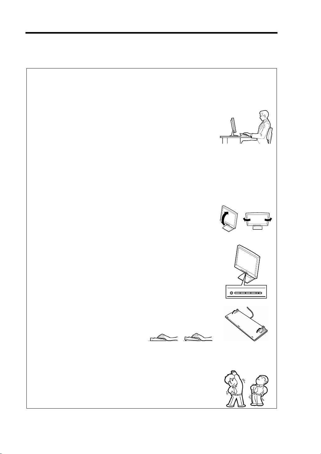
Advice for Health
The longer you keep using the computer equipment, the more you become
tired, which may cause disorders of your body. When you use a computer,
observe the following to keep yourself from getting tired:
Good Working Posture
You have good posture if the following are satisfied when you use a
computer:
• You sit on a chair with your back straight.
• Your hands are parallel with the floor when you put them on the
keyboard.
• You look at the screen slightly lower than your eye height.
You have "good working posture" as described in the above when no part
of your body is under excess strain, in other words when your muscles are
most relaxed.
You have "bad posture" when you sit with your back hunched up or you
operate a display unit with your face close to the screen. Bad working
posture may cause eye strain or poor eyesight.
Adjustment of Display Unit Angles
Most display units are designed for adjustment of the horizontal and
vertical angles. This adjustment is important to prevent the screen from
reflecting bright lights and to make the display contents easy to see. You
will not be able to keep "good working posture" and you will feel more tired
than you should if you operate a display unit without adjusting horizontal
and vertical angles.
Adjustment of Screen Brightness and Contrast
The display unit has brightness and contrast adjustment functions. The
most suitable brightness and contrast depend on the individual and the
working environment (well-lighted room or insufficient light). Adjust
brightness and contrast so that the screen will be easy to see. An
extremely bright or dark screen will give a bad effect to your eyes.
Adjustment of Keyboard Angle
The keyboard provided with the server is designed for adjustment of an
angle. Adjust the keyboard angle at which the keyboard is easy to operate.
The adjustment assists in reducing strain on your shoulders, arms, and
fingers.
Cleaning of Equipment
Clean equipment regularly. It is difficult to see the display contents on a
dusty screen. Keeping equipment clean is also important for your sight.
Fatigue and Rest
If you feel tired, you should stop working and do light exercises.
Page 25

Chapter 2
General Description
This chapter provides information that you should be familiar with before using the server. It
includes names and functions of the components and features of the server.
Page 26
2-2 General Description
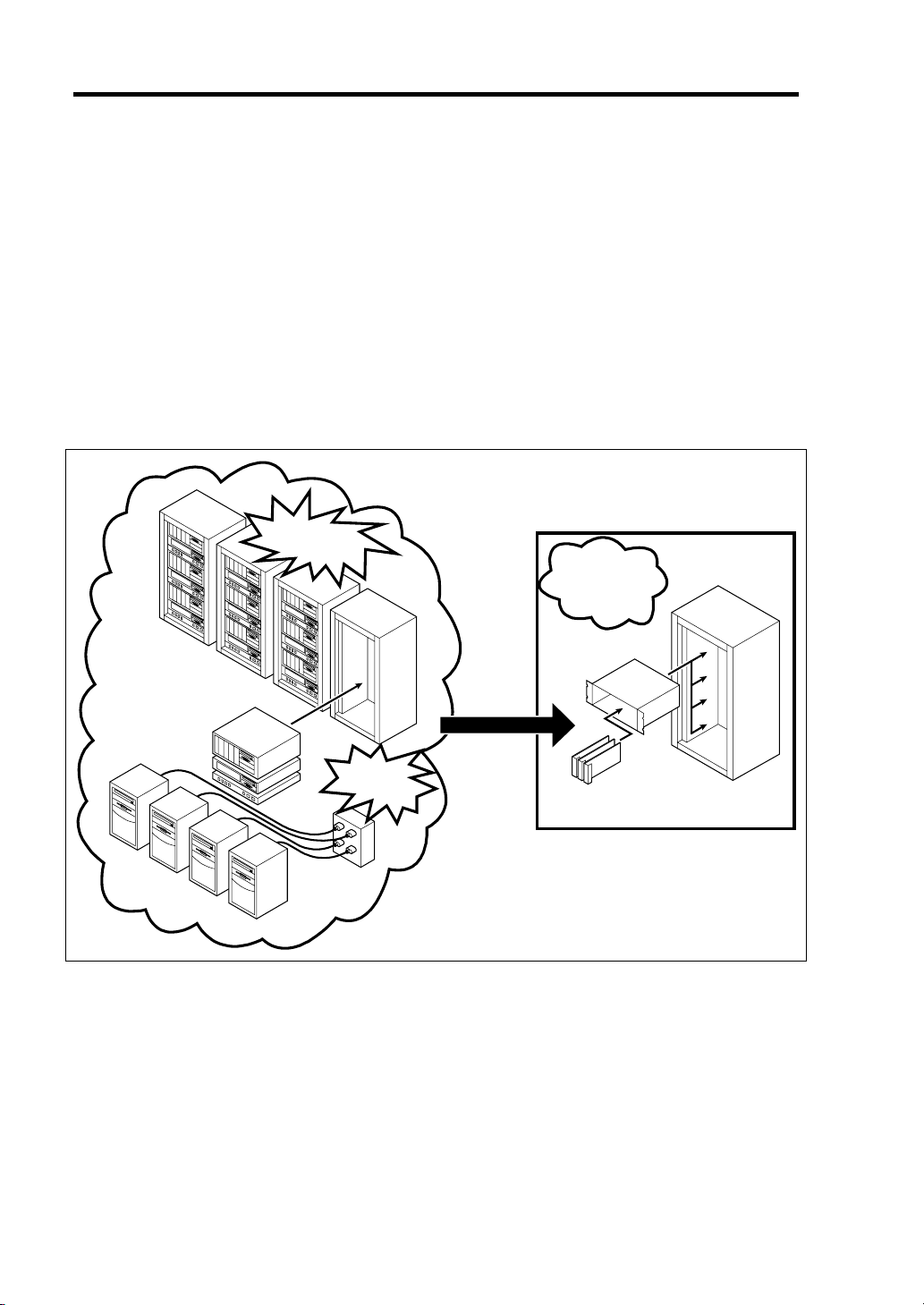
OVERVIEW
BladeServer is a modular and multiprocessing system that includes processor, memory, network
connections, optional add-in card slot, and associated electronics, all on a single mother board called
a CPU blade.
The CPU blade, hard disk drive, and other CPU blades are typically installed into a rack-mountable
enclosure that houses multiple CPU blades that share common resources such as cabling, power
supplies, and cooling fans.
This high-density technology reduces the installation space, lowers a total cost of ownership, and
offers increased computing density while ensuring both maximum scalability and ease of
management.
Increase
in installation space
Save space
and
save power
Increase in
power
consumption
Blade Enclosure
CPU blade
Page 27
STANDARD FEATURES
High performance Expandability
High-speed Intel
DDR3-1066 Registered DIMM or DDR3-
1333 Unbuffered DIMM
High-speed 1000BASE-T interface x2
(1Gbps supported)
High-speed disk access (SAS and SATA)
® Xeon® Processor
Two mezzanine card slots
Large memory of up to 64GB
Up to two multi-processors are available
for upgrade.
Two network ports
Up to two SAS or SATA hard disk drives
(2.5-inch) per CPU blade
Two USB (Ver 2.0) interface ports
High-reliability
Memory monitoring feature (correction of
correctable error/detection of
uncorrectable error)
Bus parity error detection
Temperature detection
Error notification
Internal voltage monitoring feature
BIOS password feature
Auto-rebuild feature (hot-swappable)
General Description 2-3
Management Utilities Many Available Features
NEC ESMPRO
Remote monitoring feature
(EXPRESSSCOPE engine 2)
Maintenance Features Self-diagnosis
Off-line Maintenance Utility
Memory dump feature using the DUMP
switch
Software power-off
Remote power-on feature
AC-Link feature
Power On Self-Test (POST)
Test and Diagnosis (T&D)
Easy and Fine Setup
NEC EXPRESSBUILDER (system
management tools)
SETUP (BIOS setup utility)
LSI Software RAID Configuration Utility
(RAID configuration utility)
Page 28
2-4 General Description
PART NAMES AND CONTROLS
This section describes the names and features of the sections in the device.
CPU Blade
This section describes the names, installation positions, and features of the sections on the CPU
blade.
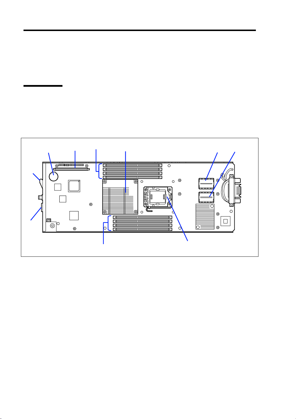
Onboard Components
1
10
9
1 Lithium battery
2 Interface card connector for hard disk drive
3 DIMM slot (CPU #1)
CPU1_DIMM1 to CPU1_DIMM4 from top
4 Heat sink
Install the processor #1 (CPU #1) below this heat sink.
5 Type 2 mezzanine slot
Slot to install mezzanine card for blade. The slot number is "MEZ2".
6 Type 1 mezzanine slot
Slot to install mezzanine card for blade. The slot number is "MEZ1".
7 DIMM slot (CPU #2)
CPU2_DIMM1 to CPU2_DIMM4 from bottom
8 Socket cover
Install the processor #2 (CPU #2) below this socket cover.
9 SUV connector
10 Eject lever
2
3
8
4
5
6
7
Page 29
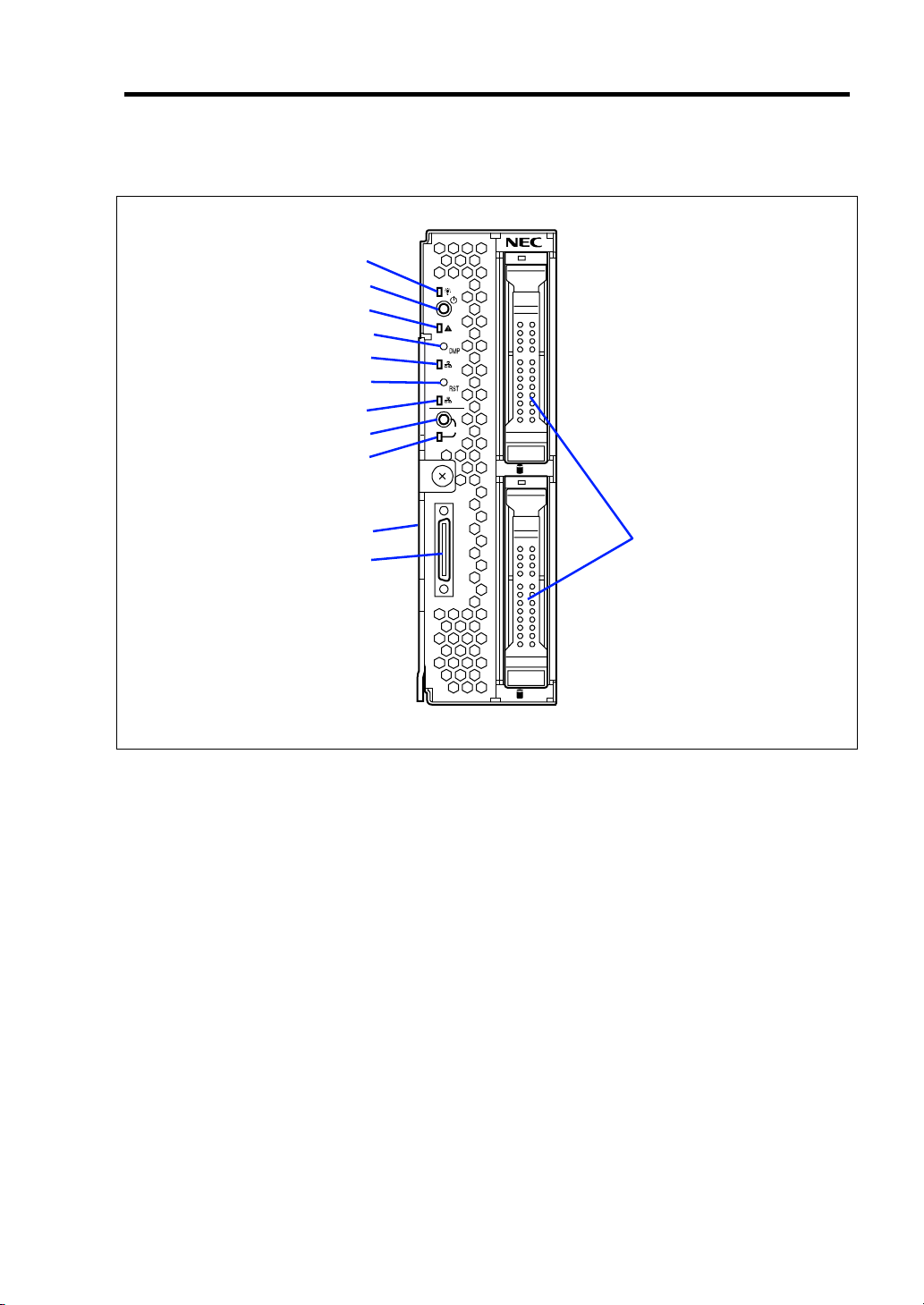
CPU Blade Access Side
General Description 2-5
1
2
3
4
5
6
7
8
9
1
2
ID
0
10
12
11
1
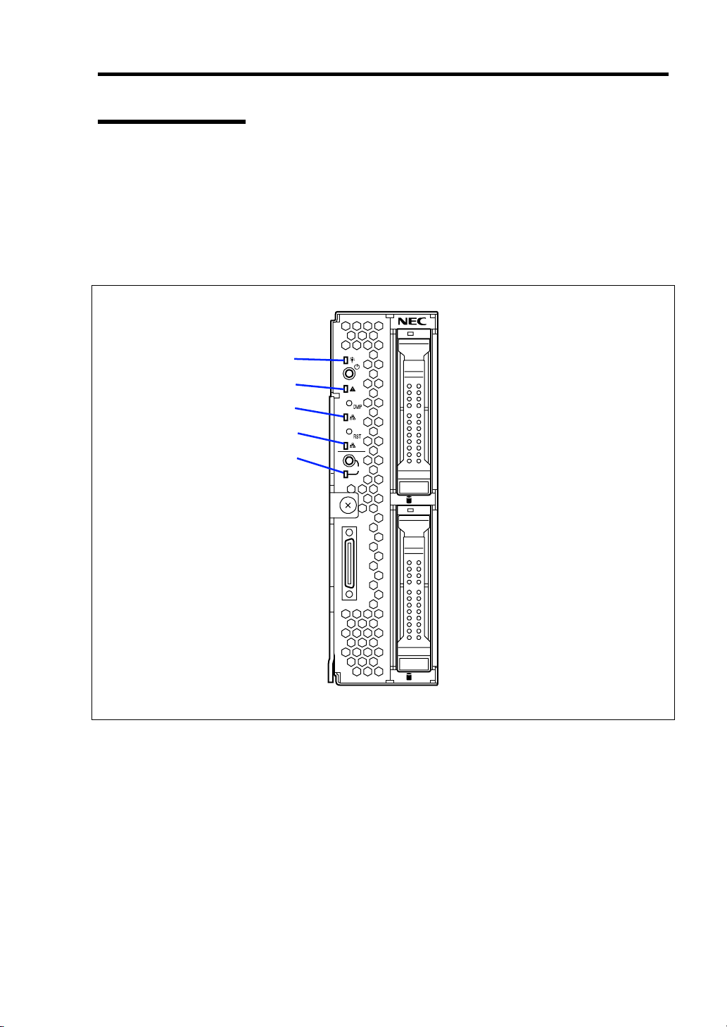
1 POWER lamp
The lamp goes on green when the CPU blade is powered on.
The lamp goes on amber when the CPU blade is powered off but the power is supplied from
the power supply unit.
2 POWER switch
The switch is intended to turn on or off the power of the CPU blade itself. Pressing the switch
for 4 seconds or longer causes the power supply to be turned off forcibly.
3 STATUS lamp (green/amber/red)
The lamp indicates the status of the CPU blade. See "Lamp Indications" described later for
the indications and meanings of the lamp.
4 DUMP switch
Press this switch to run the memory dump.
5 LAN1 Link/Access lamp (green)
The lamp goes on when LAN port 1 is connected to the network. The lamp blinks when data
is being transmitted.
6 RESET switch
Press this switch to reset the CPU blade.
7 LAN2 Link/Access lamp (green)
The lamp lights when LAN port 2 is connected to the network. The lamp blinks when data is
being transmitted.
Page 30

2-6 General Description
8ID switch
Press this switch to turn on or off the ID lamp.
9 ID lamp (blue)
The lamp is intended to identify the CPU blade in the system. The lamp is lit by a switch or
software command.
When the recognize command is received from software, the lamp blinks. If you press the ID
switch, the lamp goes on.
You may use the remote control feature of EXPRESSSCOPE Engine 2 (BMC) to perform the
same operation as using the ID switch on the server.
10 Eject lever
Pull the lever to remove the CPU blade from the Blade Enclosure.
11 SUV connector
This connector sends or receives various signals.
The K410-150(00) SUV cable is connected to this connector.
12 Hard disk drive (top: slot 0, bottom: slot 1)
Page 31

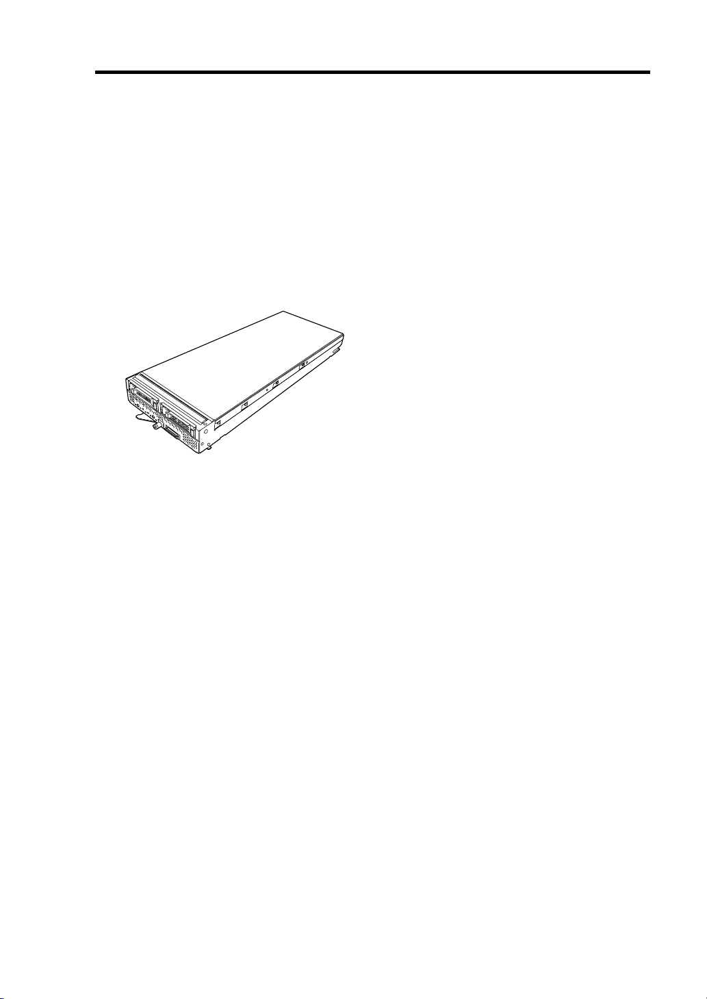
External View
Top cover
General Description 2-7
Hard disk drive bracket
CPU blade with its cover installed
Air duct cover
CPU blade with its cover removed
Page 32
2-8 General Description
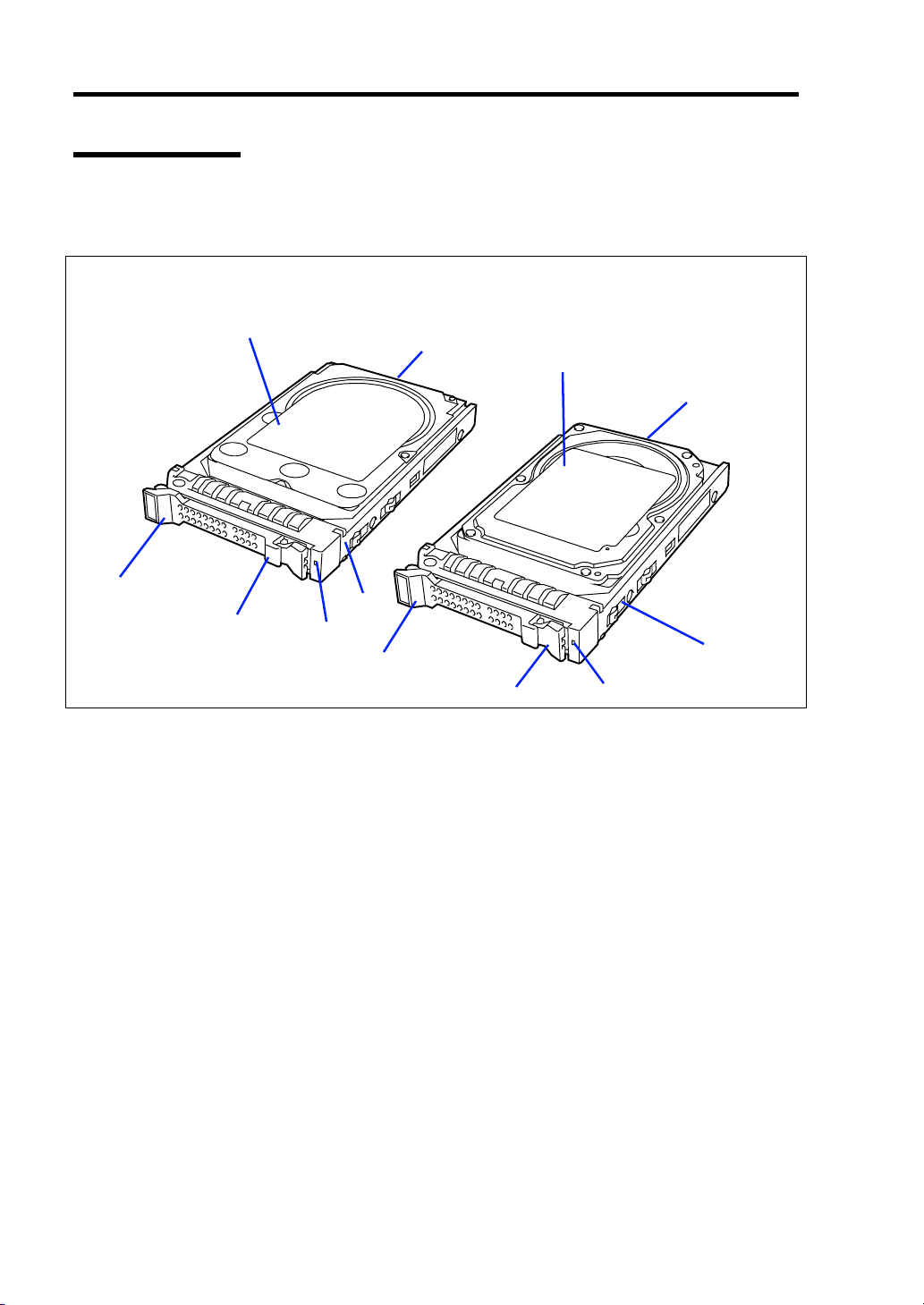
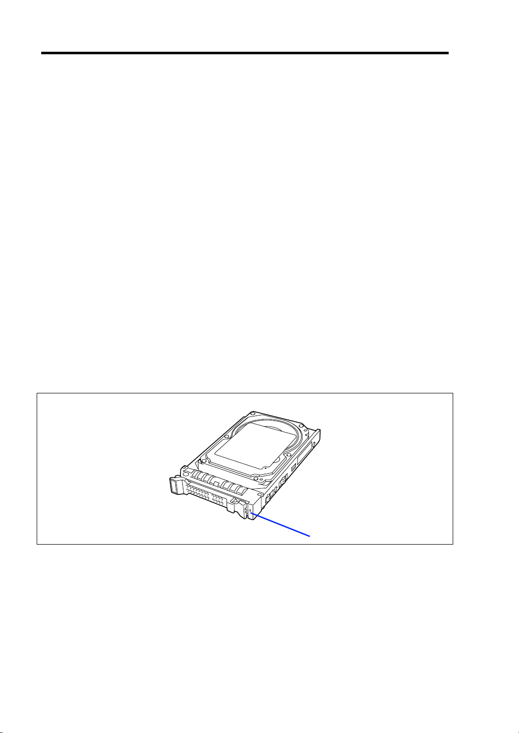
Hard Disk Drive
The hard disk drive is an optional device. An operating system may be installed in the hard disk
drive. Handle it carefully.
SATA hard disk drive
1
2
6
3
5
1 Hard disk drive
2 BP connector
Used to connect with the hard disk drive backplane in the CPU blade.
3 Drive carrier
4 Disk access lamp (green/amber)
Lights green in accessing to a hard disk drive.
Lights amber if a fault occurs in a hard disk drive. Blinks green or amber alternately or blinks
amber while array disks are rebuilt. However, when hard disk drives are operated in the array
configuration using SW RAID, the disk access lamp operates only in the OS boot status.
5 Lever
The lever is intended to fix the hard disk drive. Pull the lever to remove the hard disk drive.
6 Handle
Hold the handle when the hard disk drive is installed or removed.
4
6
5
SAS hard disk drive
1
2
4
3
Page 33
General Description 2-9
Lamp Indications
This section describes the positions and display meanings of the lamps on the CPU blade and hard
disk drive.
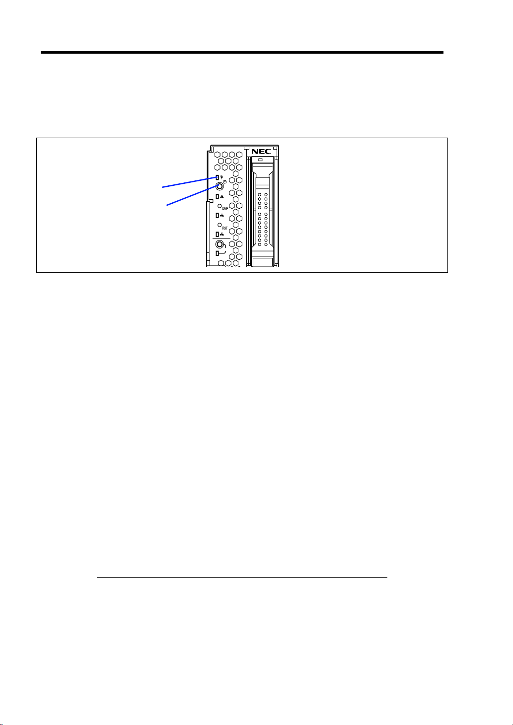
CPU Blade
The CPU blade includes five lamps.
POWER lamp
STATUS lamp
LAN1 Link/Access lamp
LAN2 Link/Access lamp
ID lamp
1
2
ID
0
1
POWER Lamp
The POWER lamp lights green while the power of the CPU blade is on. The lamp lights amber
when the CPU blade is powered off but the power is supplied from the power supply unit. The lamp
is off if the power is not supplied to the system.
Page 34

2-10 General Description
STATUS Lamp
The STATUS lamp stays lit in green when the CPU blade is in successful operation. When the
STATUS lamp is flashing in amber or red, it indicates that the system has failed.
In addition, you can view the detailed information on error message on virtual LCD when the
STATUS lamp is flashing in amber or red.
You can use the virtual LCD through the Web browser of EXPRESSSCOPE engine (BMC) or NEC
ESMPRO Manager.
The following table lists indications of the STATUS lamp, descriptions, and actions to take.
If an error occurs, contact your service representative.
NOTE: If the CPU blade has the NEC ESMPRO installed, you can
view the System Event Log (SEL) to identify the cause of a trouble.
STATUS lamp indications
STATUS lamp
Status Color
On Green The CPU blade is operating
Off –
On Red BMC is being initialized.
Flash Red
Flash Amber
Description Action
normally.
The power is turned off.
See the table "Virtual LCD indications when STATUS lamp is flashing in
red" described later.
See the table "Virtual LCD indications when STATUS lamp is flashing in
amber" described later.
NOTE: If the CPU blade is powered off while the STATUS lamp is
flashing in amber or red, the indication of the STATUS lamp is retained
except for certain factors. When the CPU blade is powered on, the
STATUS lamp goes on green (normal status).
–
Turn on the power.
1. Wait until the lamp goes off.
2. If the lamp still goes on, check
installation of the CPU blade.
Page 35

Virtual LCD indications when STATUS lamp is flashing in red
On-screen message Description Action
Proc 1 IERR An error was detected in CPU#1.
Proc 2 IERR An error was detected in CPU#2.
WDT Timeout Watchdog timer timeout error
occurred.
WDT Power Down Forcedly powered off due to
watchdog timer timeout error.
SMI Timeout A timeout error occurred while the
system management interrupt
process is in progress.
ErrPause in POST
DUMP Request ! Under memory dump request
CPU1_DIMM U-Err
CPU2_DIMM U-Err
Proc Missing No CPU is installed in slot CPU#1.
Proc1 Config Err The CPU installed in the CPU#1 slot
Proc2 Config Err The CPU installed in the CPU#2 slot
MEZ1 Power Fault An error was detected in power
MEZ2 Power Fault An error was detected in power
IOH Thermal Trip
Proc1ThermalTrip Forced power-off occurred due to a
Proc2ThermalTrip Forced power-off occurred due to a
Proc1 Therm % 09 A high temperature error was
Proc2 Therm % 09 A high temperature error was
CPUx_DIMMyTemp09 A high temperature error was
AmbientTempAlm09 A high temperature error was
The system is waiting for key entry
due to serious POST error.
An uncorrectable memory error was
detected on CPU1_DIMM.
An uncorrectable memory error was
detected on CPU2_DIMM.
is unsupported or its combination is
illegal.
is unsupported or its combination is
illegal.
circuit of mezzanine card installed in
Type 1 slot of CPU blade.
circuit of mezzanine card installed in
Type 2 slot of CPU blade.
Forced power-off occurred due to a
thermal error in chipset on CPU
blade.
thermal error in CPU#1.
thermal error in CPU#2.
detected in CPU #1.
detected in CPU #2.
detected in DIMM. x denotes CPU
number, and y denotes DIMM slot
number.
detected in CPU blade.
Turn of the power once and then
on again.
If an error message appears on
POST screen, take note of the
message, and contact your service
representative.
If no error message appears,
check the IPMI information by
using the Off-line Maintenance
Utility.
Check the error message on
POST screen, take note of it, and
contact your service
representative.
Wait until dump collection
completes.
Check installation status DIMM.
If the same error persists, contact
your service representative.
Check installation status of CPU.
If the same error persists, contact
your service representative.
Check installation status of
mezzanine card.
If the same error persists, contact
your service representative.
Check installation status of the
heat sink on the CPU blade.
Check if fans in Blade Enclosure
work normally.
Refer to the User’s Guide of the
Blade Enclosure to make sure that
the sufficient number of fans are
installed in correct locations.
Check if the fans and CPU blades
are installed in correct locations.
Check if the ambient temperature
of installation location satisfies the
operation guarantee condition.
If the same error persists, contact
your service representative.
General Description 2-11
Page 36

2-12 General Description
On-screen message Description Action
AmbientTempAlm02
P1 VCCP Alm XX
P1 VTT Alm XX
P1 VDDQ Alm XX
P1 DDR_VTT AlmXX
P2 VCCP Alm XX
P2 VTT Alm XX
P2 VDDQ Alm XX
P2 DDR_VTT AlmXX
BB +1.1v Alm XX
BB +1.5v Alm XX
BB +1.8v Alm XX
BB +3.3v Alm XX
BB +5v Alm XX
BB +0.9vs Alm XX
BB +1.1vs Alm XX
BB +1.8vs Alm XX
BB +3.3vs Alm XX
BB +5vs Alm XX
BB +12vs Alm XX
Battery Alm XX
A low temperature error was
detected in CPU blade.
A voltage alarm was detected.
XX=09: Upper limit alarm
XX=02: Lower limit alarm
Check if the ambient temperature
of installation location satisfies the
operation guarantee condition.
If the same error persists, contact
your service representative.
Contact your service
representative.
Virtual LCD indications when STATUS lamp is flashing in amber
On-screen message Description Action
Mem Reconfigured
Mem Err Disable
CPU Reconfigured The failing CPU is forcedly used. Check installation status of CPU.
HDD X Fault An error was detected in hard
E-Keying Error In the Blade Enclosure,
The failing memory is forcedly
used, or the memory is degraded.
Correctable memory error
frequently occurs.
disk drive installed in CPU blade.
X: Indicates slot number
containing the failing hard disk
drive with 0-origin number.
combination of installation
locations of CPU blade,
mezzanine card, and switch
module is not correct. Thus, an
unconformity of interface signal
was detected and the CPU blade
failed to power on.
Check installation status of DIMM.
If the same error persists, contact your
service representative.
If the same error persists, contact your
service representative.
Contact your service representative.
Refer to the User's Guide of Blade
Enclosure for correct installation
locations.
If the same error persists, contact your
service representative.
Page 37

On-screen message Description Action
Location Error
Cooling Error In the Blade Enclosure, the
Proc1 Therm % 07 A high temperature warning was
Proc2 Therm % 07 A high temperature warning was
CPUx_DIMMyTemp07 A high temperature warning was
AmbientTempAlm07 A high temperature warning was
AmbientTempAlm00 A low temperature warning was
P1 VCCP Alm XX
P1 VTT Alm XX
P1 VDDQ Alm XX
P1 DDR_VTT AlmXX
P2 VCCP Alm XX
P2 VTT Alm XX
P2 VDDQ Alm XX
P2 DDR_VTT AlmXX
BB +1.1v Alm XX
BB +1.5v Alm XX
BB +1.8v Alm XX
BB +3.3v Alm XX
BB +5v Alm XX
BB +0.9vs Alm XX
BB +1.1vs Alm XX
BB +1.8vs Alm XX
BB +3.3vs Alm XX
BB +5vs Alm XX
BB +12vs Alm XX
Battery Alm XX
In the Blade Enclosure, the
installation location of CPU blade
is incorrect, or the installation
locations of the fan and CPU
blade are incorrect. Thus, the
CPU blade failed to power on.
number of fans installed is
insufficient or the installed fan is
faulty. Thus, the CPU blade failed
to power on due to insufficient
cooling power.
detected in CPU #1.
detected in CPU #2.
detected in DIMM.
x, y: Indicates location of DIMM
slot.
detected in CPU blade.
detected in CPU blade.
A voltage warning was detected
on CPU blade.
XX=07: Upper limit warning
XX=00: Lower limit warning
Refer to the User's Guide of Blade
Enclosure to check if the CPU blade is
installed in correct location.
Check the installation locations of the fan
and CPU blade.
If the same error persists, contact your
service representative.
Check if the heat sink is installed
correctly on CPU blade.
Check if fans in Blade Enclosure work
normally.
Refer to the User’s Guide of the Blade
Enclosure to make sure that the
sufficient number of fans are installed in
correct locations.
Check if the fans and CPU blades are
installed in correct locations.
Check if the ambient temperature of
installation location satisfies the
operation guarantee condition.
If the same error persists, contact your
service representative.
Check if the ambient temperature of
installation location satisfies the
operation guarantee condition.
If the same error persists, contact your
service representative.
Contact your service representative.
General Description 2-13
Page 38
2-14 General Description
LAN (1 - 2) Link/Access Lamps
The lamp goes on when LAN port is connected to the network. The lamp blinks when data is being
transmitted. When the CPU blade is powered on and the LAN cable is connected, the lamp on LAN
port for which the link is being established goes on. The connection of LAN port is physically
controlled by the EM card and the switch module installed in the Blade Enclosure.
To check connection status of LAN port, refer to the User's Guide of the EM card and the switch
module installed in the Blade Enclosure.
ID Lamp
Pressing the ID switch brings the lamp to light, and pressing again brings the lamp to go off. The ID
lamp is intended to identify a specific CPU blade in the system in which more than one CPU blade
is installed. Making this lamp being lit can help the maintenance work to identify the faulty device.
If you press the ID switch, the lamp goes on. When the recognize command is received from
management software such as NEC ESMPRO Manager, the lamp blinks.
You may use the remote control feature of EXPRESSSCOPE Engine 2 (BMC) to perform the same
operation as using the ID switch on the server.
Hard Disk Drive
A single hard disk drive includes one lamp.
DISK ACCESS lamp
The lamp lights while accessing to a hard disk drive occurs (however, if the hard disk drive is
operated in the array configuration using SW RAID, the lamp operates only in the OS boot status).
The lamp is lit amber if a hard disk drive cannot be interfaced with the CPU blade correctly due to a
hardware fault in the CPU blade or another failure.
In the disk array configuration, the lamp blinks green or amber alternately while the disk array is
rebuilt (this does not indicate an error). After the rebuilding completes, the lamp returns to the
normal indication. If the rebuilding fails, the lamp is lit amber.
Page 39

General Description 2-15
USING YOUR SERVER
This section describes the basic operation of the blade server.
Power-on of Blade Server
There are the following two ways to turn on the power of the CPU blade. Turn on the power of the
CPU blade in any of the two ways after turning on the powers of the display unit and peripherals
connected to the CPU blade.
IMPORTANT: Perform the power-on operation of the CPU blade by
either the use of the POWER switch or the remote power-on after the
period of 30 seconds or longer has passed from the supply of AC power
to every power unit. The power-on operation within the period of 30
seconds from the supply of AC power to every power unit may not turn
on the power of the CPU blade. If so, turn on the power of the CPU
blade by using the POWER switch after making sure that the AC power
is supplied to every power unit.
NOTES:
If a power cord on the Blade Enclosure is connected to a power
controller including an uninterruptible power supply (UPS), make
sure that the power of the power controller is turned on.
When the power is supplied to the server, the initial diagnosis is
executed for about 30 seconds. In this period, the POWER switch is
disabled. Power on the server about 30 seconds immediately after
you installed the CPU blade or turned on the server.
Page 40
2-16 General Description
Power ON from CPU Blade
Press the POWER switch on the panel of the CPU blade (the POWER lamp on the CPU blade goes
on green).
POWER lamp
POWER switch
1
2
ID
Power ON from Network Serial Port
Depending on the BIOS setting of the CPU blade, the power of the CPU blade may be automatically
turned on by a proper packet received from the network or via the modem connected to the serial
port.
This power-on procedure can be specified by setting [Wake On Events] of [System Hardware] in the
BIOS SETUP Utility.
Power ON from Remote Console
The power of the CPU blade can be turned on by using remote control feature of EXPRESSSCOPE
Engine 2 (BMC).
Operation after Power ON
If the CPU blade is connected with a display unit, the NEC logo appears on the screen of the display
unit after a while from the power-on.
While the NEC logo appears, the CPU blade runs the self-diagnosis program (POST) to diagnose
the CPU blade itself. See "POST" described later for details. At the completion of POST, OS is
booted.
NOTE: If a fault is found during POST, it is interrupted and the error
message notifying the fault appears. See Chapter 8.
Page 41

General Description 2-17
Power-off of Blade Server
There are the following three ways to turn off the power of the CPU blade.
1. Power-off by OS shutdown
2. Power-off from CPU Blade
Press the POWER switch on the panel of the CPU blade
3. Power-off from Remote Console
The power of the CPU blade can be turned off by using "OS Shutdown" in remote control
feature of EXPRESSSCOPE Engine 2 (BMC).
The POWER lamp on the CPU blade of which power was turned off goes on amber.
NOTE: To power-off from CPU blade or remote console, the OS must
be set so that it starts shutdown process when the POWER switch on
the CPU blade is pressed.
POST
POST (Power On Self-Test) is the self-diagnostic program stored in the CPU blade.
When you power on the CPU blade, the system automatically runs POST to check the mother board,
ECC memory module, CPU module, keyboard, and mouse. POST also displays messages of the
BIOS SETUP utility, such as the start-up message, while in progress.
With the factory setup of the CPU blade, the NEC logo appears on the display unit (if connected)
while POST is in progress. To display the POST check results, press Esc.
NOTE: You can set the POST check results to appear on the display
unit without pressing Esc. To do so, select "Enabled" for "Boot-time
Diag Screen" under the Advanced menu of the BIOS SETUP utility.
See Chapter 4 for details.
You don't always need to check the POST check results. Check messages that POST displays when:
you use the blade server for the first time.
the server appears to fail.
an error message appears on the display unit.
Page 42

2-18 General Description
POST Execution Flow
The following describes the progress of POST in the chronological order.
IMPORTANT:
Do not make unnecessary key entries or perform mouse operations
while POST is in progress.
Some system configurations may display the message "Press Any
Key" to prompt a key entry. This message is driven by BIOS of an
installed optional board. Make sure to read the manual that comes
with the optional board before any key entry.
Powering on the server, after you installed or removed an optional
mezzanine card, may display the message that indicates incorrect
board configuration and suspend POST.
In such a case, press F1 to continue POST. Board configuration can
be made using the utility described later.
1. After a few seconds from power-on, POST starts checking the memory. The count
message of the basic and expansion memory appears on the screen of the display unit (if
connected). The memory check may takes a few minutes to complete depending on the
memory size of the CPU blade. Also, it may take approximately one minute for the screen
display to appear after rebooting the CPU blade.
2. Some messages appear upon completion of the memory check. These messages appear to
indicate that the system has detected the CPU and other devices installed.
3. After a few seconds, POST displays the following message prompting you to launch the
BIOS setup utility, SETUP, stored in the system memory of the CPU blade. This message
appears at bottom left on the screen.
Press <F2> to enter SETUP
Launch the BIOS SETUP utility when you need to change the settings to meet the
requirements for the CPU blade. As long as the above message is not displayed with an
error message, you don't have to launch the utility. (Ignore the message. POST will
automatically proceed.)
To launch the SETUP utility, press F2 while the above message is displayed. See Chapter
4 for setup and parameters.
The CPU blade automatically restarts POST all over again when you exit the SETUP
utility.
4. If the server has an optional board installed, POST displays the board information on the
screen.
Refer to the manual supplied with the board for details.
POST will automatically proceed a few seconds later.
Page 43

General Description 2-19
5. If you have set the password using the BIOS SETUP utility, the password entry screen
appears upon successful completion of POST.
Up to three password entries will be accepted. Three incorrect password entries disable
the system to boot. In such a case, turn off the power and wait about 30 seconds before
turning on to boot the CPU blade.
IMPORTANT: Do not set a password before installing an OS.
6. The OS starts when POST completes.
POST Error Messages
When POST detects an error, it displays an error message on the screen. See Chapter 8 for POST
error codes.
IMPORTANT: Take a note on the messages displayed before
consulting with your service representative. Alarm messages are useful
information for maintenance.
Page 44

2-20 General Description
Device Identification
To identify the device to be maintained among more than one device, ID lamp is used.
The ID lamp is located on the CPU blade installed in the Blade Enclosure.
The ID lamp allows you to identify the device subject to maintenance among more than one CPU
blade installed in the Blade Enclosure.
The ID lamp on CPU blade can also be made blink blue by proper software commands from the
management PC on the network. In addition, pressing the ID switch on the CPU blade brings the ID
lamp to light.
You may use the remote control feature of EXPRESSSCOPE Engine 2 (BMC) to perform the same
operation as using the ID switch on the CPU blade.
1
ID switch
ID lamp
2
ID
0
1
Page 45

Chapter 3
Setting Up Your Server
This chapter describes how to set up the server appropriate for your system, on a step-by-step basis.
Page 46

3-2 Setting Up Your Server
BEFORE INSTALLING CPU BLADE
Be sure to check the MAC addresses before installing a CPU blade in the Blade Enclosure.
Check of MAC Address
A MAC address indicates the address specific for the network. It is expressed by 12-digit
alphanumeric starting with "003013". A CPU blade has two MAC addresses. Check the MAC
addresses before installing a CPU blade in the Blade Enclosure.
A MAC address is indicated in the area as shown in the figure below.
Label indicating
MAC address
The address of LAN port depends on the numeral and alphabet of the last digit of MAC address.
When the numeral/alphabet of the last digit is even number, A, C, or E:
The MAC address for LAN port 1 is as described on the label.
The MAC address for LAN port 2 can be obtained by adding 1 to the described MAC
address.
When the numeral/alphabet of the last digit is odd number, B, D, or F:
The MAC address for LAN port 1 can be obtained by adding 1 to the described MAC
address.
The MAC address for LAN port 2 can be obtained by adding 2 to the described MAC
address.
The MAC addresses can be checked from the proper Windows or Linux command.
Windows
Enter "ipconfig /all" for the MS-DOS prompt or from [Run] in the Start menu to see the
indicated physical address part.
Linux
Enter "ifconfig" for the prompt to see the indicated "Hwaddr".
You may use the remote control feature of EXPRESSSCOPE Engine 2 (BMC) to check the MAC
address.
Installing DIMM
If your CPU blade is not equipped with memory device, install DIMMs according to Chapter 9.
Page 47

Setting Up Your Server 3-3
INSTALLING THE CPU BLADE
Install the CPU blade in the dedicated Blade Enclosure. Refer to the User's Guide of Blade
Enclosure for how to install the CPU blade.
IMPORTANT: The CPU blade is extremely sensitive to static
electricity. Make sure to touch the metal frame of the CPU blade to
discharge static electricity from your body before handling the CPU
blade. Do not touch the pins, leads, or circuitry and place the CPU
blade directly on the desk. For static notes, see "Anti-static Measures"
in Chapter 9.
INSTALLING THE HARD DISK DRIVE
Install a hard disk drive according to the procedure described in Chapter 9.
IMPORTANT:
The hard disk drive is extremely sensitive to static electricity. Make
sure to touch the metal frame of the CPU blade to discharge static
electricity from your body before handling the hard disk drive. Do
not touch the pins, leads, or circuitry and place the hard disk drive
directly on the desk. For static notes, see "Anti-static Measures" in
Chapter 9.
Some hard disk drive may contain operating system. Strict care
must be taken when handling it.
Handle the hard disk drive carefully so that the hard disk drive may
not be given excess shocks and vibrations.
Page 48
3-4 Setting Up Your Server
MAKING CONNECTIONS
Connect peripheral devices to the CPU blade.
IMPORTANT:
Contact the maintenance engineer in your service representative if
you have any requests on the system configuration including the
connection to the uninterruptible power supply system or auto
power controller and the time schedule operation.
If you are installing the CPU blade in the Blade Enclosure
(SIGMABLADE), follow instructions described in the User's Guide
of the Blade Enclosure.
Observe the following instructions to use the server safely. Failure to follow
these instructions may result in death or serious personal injury. See pages 1-2
to 1-6 for details.
■ Do not hold the power plug with a wet hand.
■ Do not connect earth lines to any gas tubes.
WARNING
CAUTION
Observe the following instructions to use the server safely. Failure to follow
these instructions may cause a fire, personal injury, or property damage. See
pages 1-2 to 1-6 for details.
■ Do not plug the power cord in to an improper power source.
■ Do not connect the power cord to an outlet that has an illegal number of
connections.
■ Insert the power plug into the outlet as far as it goes.
■ Use the authorized power cord only.
■ Do not connect or disconnect any interface cable with the power cord of the
server plugged to a power source.
■ Do not use any unauthorized interface cable.
Page 49
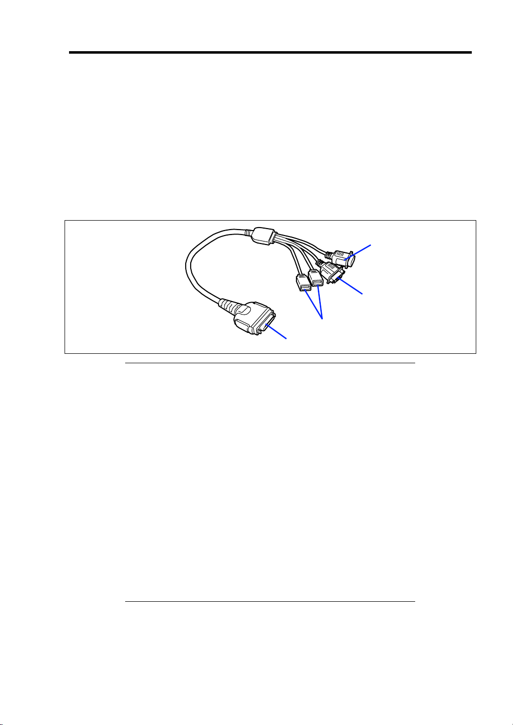
Setting Up Your Server 3-5
In the ordinary operation, any cables may not be connected to a CPU blade. Proper cable(s) should
be connected to the USB, serial, and/or VGA ports on the CPU blade in the following cases:
Installing OS (when the CPU blade is installed in the Blade Enclosure (SIGMABLADE-
H))
Maintenance
Updating BIOS and firmware
The K410-150(00) SUV cable is a standard accessory for the Blade Enclosure (SIGMABLADE).
The K410-150(00) SUV cable has the USB, serial interface, and monitor connection connectors at
the other ends. Connect a proper device at each of the ends.
To serial interface device
To monitor
To USB devices
To CPU blade
IMPORTANT:
To connect a peripheral or interface cable provided by a vendor
other than NEC (or third party) to the CPU blade, make sure that the
device is available for the CPU blade. Some third party devices are
not available for the CPU blade.
The serial port connector cannot be directly connected with the
leased line.
Do not connect/disconnect the SUV cable or add/remove the USB
device until the operating system starts running.
To connect/disconnect the SUV cable or add/remove the USB
device after OS startup, follow restrictions of operating system.
If the device having serial interface is connected, first power off the
CPU blade and destination device, and remove the power cord from
the destination device before connecting/disconnecting SUV cable
or serial cable. Failure to follow it may cause the devices to be
defected due to the potential difference between them.
If the CPU blade is installed in the Blade Enclosure
(SIGMABLADE-H) and you are going to install an OS in it, use the
SUV cable. See the next page for connection.
Page 50
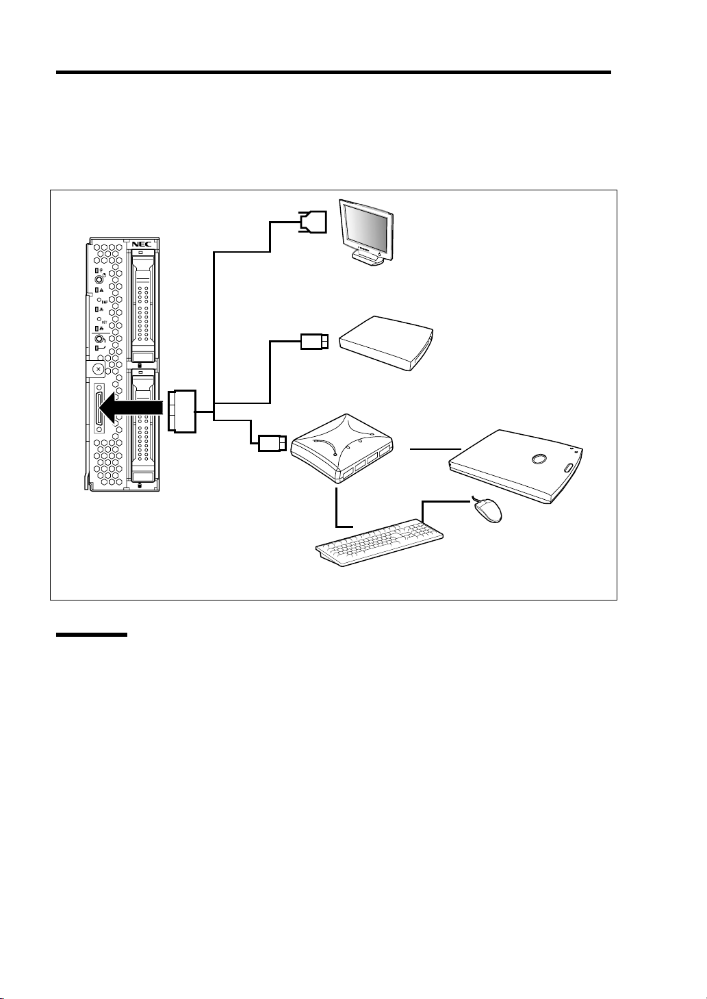
3-6 Setting Up Your Server
USB Connection by K410-150(00) SUV Cable
Connect the floppy disk drive, DVD-ROM drive, keyboard, and mouse according to the figure
shown below.
Display unit
1
2
ID
0
USB
External floppy disk drive
External DVD-ROM drive *
USB
1
CPU blade
* Use the USB hub and external DVD-ROM
drive supported by this CPU blade.
Self-powered
USB hub *
Mouse
Keyboard
Network
The CPU blade is connected with network via the Blade Enclosure. Refer to the User's Guide of the
Blade Enclosure for details.
Page 51

Chapter 4
Configuring Your Server
This chapter describes Basic Input Output System (BIOS) configuration.
When you install the blade server for the first time or install/remove optional devices, thoroughly
read this chapter for better understanding and correct setups.
SYSTEM BIOS ~ SETUP ~
The SETUP utility is provided to make basic hardware configuration for the CPU blade. This utility
is pre-installed in the flash memory of the CPU blade and ready to run.
The CPU blade is configured with the correct parameters using the SETUP utility and shipped in the
best conditions. Thus, you don't need to use the SETUP utility in most cases. However, you might
wish to use the SETUP utility in the cases described below.
IMPORTANT:
The SETUP utility is intended for system administrator use only.
The SETUP utility allows you to set a password. The CPU blade is
provided with two levels of password: Supervisor and User. With
the Supervisor password, you can view and change all system
parameters of the SETUP utility. With the User password, system
parameters available for viewing and changing are limited.
Do not set any password before installing the OS.
The CPU blade contains the latest version of the SETUP utility.
Dialog boxes appear on your SETUP utility, thus, may differ from
descriptions in this manual. If you find anything unclear, see the
online help or ask your sales representative.
Page 52

4-2 Configuring Your Server
Starting SETUP Utility
Powering on the CPU blade starts POST (Power On Self-Test) and displays its check results. If the
NEC logo is displayed, press Esc.
After a while, the following message appears at bottom left on the screen.
Press <F2> to enter SETUP
Press F2 to start the SETUP utility and display its Main menu.
If you have previously set a password with the SETUP utility, the password entry screen appears.
Enter the password.
Enter password:[ ]
Up to three password entries will be accepted. If you fail to enter the password correctly for three
consecutive times, the CPU blade halts. (You can no longer proceed.) Power off the CPU Blade.
NOTE: The CPU blade is provided with two levels of password:
Supervisor and User. With the Supervisor password, you can view and
change all system parameters. With the User password, system
parameters available for viewing and changing are limited.
Page 53

Configuring Your Server 4-3
Description on On-Screen Items and Key Usage
Use the following keyboard keys to work with the SETUP utility. (Key functions are also listed at
the bottom of the screen.)
Indicates
there are
submenus.
Setup item
menu
Indicates the current menu.
Online help
window
Explanation of key functions
Cursor (↑, ↓):
Selects an item on the screen. The highlighted item is currently
Parameter (high-lights upon selection) menu
selected.
Cursor (←, →):
Selects the Main, Advanced, Security, Server, Boot, or Exit menu.
– and +: Changes the value (parameter) of the selected item. When a
submenu option (an option preceded by "
³") is selected, these
keys are disabled.
Enter: Press Enter to select (determine) parameters.
Esc:
Displays the previous screen.
F1: Press F1 when you need help on SETUP operations. The help
screen for SETUP operations appears. Press Esc to return to the
previous screen.
F9:
Sets the parameter of the currently displayed item back to the
factory set parameter.
F10:
Save and exit the SETUP utility.
Page 54

4-4 Configuring Your Server
Menu and Parameter Descriptions
The SETUP utility has the following six major menus:
Main
Advanced
Security
Server
Boot
Exit
To set minute functions, select a submenu from the above menus. The following describes available
functions and parameters, as well as the factory-set, for each menu.
Page 55

Configuring Your Server 4-5
Main
Option Parameter Description Your Setting
System Time HH:MM:SS Set the system time.
System Date MM/DD/YYYY Set the system date.
Hard Disk Pre-Delay [Disabled]
3 seconds
6 seconds
9 seconds
12 seconds
15 seconds
21 seconds
30 seconds
Processor Settings Select submenu
When accessing the internal
SATA hard disk drive for the first
time during POST, the system
waits for the specified time until
the drive becomes ready.
Shows the processor settings
submenu.
[ ]: Factory-set
IMPORTANT: Check and adjust the system clock before the
operation if any of the following conditions is applicable.
After carriage of device
After storage of device
After the device is entered into the pause state under the
environmental condition enduring device operation (temperature:
10°C - 35°C, humidity: 20% - 80%)
Check the system clock at the rough rate of once per month. When the
system clock is installed in a system requiring high time precision, it is
recommended to use a time server (NTP server).
If the system clock is remarkably delayed or advanced as the passage of
time in spite of adjustment, contact your service representative for
maintenance.
Page 56

4-6 Configuring Your Server
Processor Settings
Option Parameter Description Your Setting
Processor Speed Setting nnn GHz Displays clock speed for the
processor. (View only)
Processor 1 CPUID Numeral
Disabled
Not Installed
Error
Processor 1 L2 Cache nnn KB Displays L2 cache size for
Processor 1 L3 Cache nnn KB Displays L3 cache size for
Processor 2 CPUID Numeral
Disabled
Not Installed
Error
Processor 2 L2 Cache nnn KB Displays L2 cache size for
Processor 2 L3 Cache nnn KB Displays L3 cache size for
Active Processor Cores [ALL]
1
Hyper Threading
Technology
Execute Disable Bit [Enabled]
Intel SpeedStep(R)
Technology
C1 Enhanced Mode [Enabled]
Virtualization Technology [Enabled]
Hardware Prefetcher [Enabled]
Adjacent Cache Line
Prefetch
[Enabled]
Disabled
Disabled
[Enabled]
Disabled
Disabled
Disabled
Disabled
[Enabled]
Disabled
Displays CPU ID for processor, if
present.
"Disabled" indicates that the
processor is defected.
"Not Installed" indicates that no
processor is installed.
"Error" indicates that the processor
is forcedly booted. (View only)
processor.
processor.
Displays CPU ID for processor, if
present.
"Disabled" indicates that the
processor is defected.
"Not Installed" indicates that no
processor is installed.
"Error" indicates that the processor
is forcedly booted. (View only)
processor.
processor.
Specifies the number of valid cores
in the processor.
TBD
Displayed only when the CPU
supports Execute Disable Bit.
Fixed to "Disabled" if the processor
does not support this feature.
Enables or disables the C1
Enhanced Mode.
Enables or disables the Intel(R)
virtualization technology.
Enables or disables the hardware
prefetcher.
Enables or disables the optimization
of an access from memory to cache.
[ ]: Factory-set
Page 57

Configuring Your Server 4-7
Advanced
Option Parameter Description Your Setting
Memory Configuration – Displays Memory Configuration
submenu.
PCI Configuration – Displays PCI Configuration
submenu.
Peripheral Configuration – Displays Peripheral Configuration
submenu.
Advanced Chipset Control – Displays Advanced Chipset Control
submenu.
Boot-time Diagnostic
Screen
Reset Configuration Data [No]
NumLock On
Memory/Processor Error [Boot]
[Disabled]
Enabled
Yes
[Off]
Halt
When disabled, the BIOS will display
the NEC logo during POST. Press
Esc to switch to the POST execution
screen.
Select "Yes" if you want to clear the
system configuration data during the
next boot. Automatically reset to
"No" in the next boot.
Sets power on Numlock state.
If "Halt" is selected, the boot is
stopped when POST error occurs.
[ ]: Factory-set
IMPORTANT: Be sure to take a note of boot priority before selecting
"Yes" for [Reset Configuration Data], because the information on boot
device will be cleared. Select [Exit Saving Changes] to reboot the
system, run BIOS SETUP utility, and provide settings for boot device
order again.
Page 58

4-8 Configuring Your Server
Memory Configuration
Option Parameter Description Your Setting
Installed memory nnn MB Indicates the total capacity of the basic
memory. (View only)
Available under
4GB
CPU1_DIMM1-4
Status
nnnnnnn MB Indicates the capacity of memory
available in the area under 4GB. (View
only)
Normal
Disabled
Not installed
Error
Indicates the current memory status
installed in CPU1_DIMM1 to
CPU1_DIMM4.
"Normal" indicates the normal status,
"Disabled" indicates a memory error, "Not
installed" indicates no DIMM installed, and
"Error" indicates the system is forcibly
started with memory error. (View only).
CPU2_DIMM1-4
Status
Memory Retest [No]
Extended RAM
Step
Memory RAS
Mode
NUMA
configuration
Normal
Disabled
Not installed
Error
Yes
1MB
1KB
Every location
[Disabled]
[Independent]
Mirror
Lock Step
[Disabled]
Enabled
Indicates the current memory status
installed in CPU2_DIMM1 to
CPU2_DIMM4.
"Normal" indicates the normal status,
"Disabled" indicates a memory error, "Not
installed" indicates no DIMM installed, and
"Error" indicates the system is forcibly
started with memory error. (View only).
Causes BIOS to retest all memory on the
next boot.
"1MB" indicates that the memory test is
done in the unit of 1MB. "1KB" indicates
that the memory test is done in the unit of
1KB. "Every location" tests every memory
location. "Disabled" indicates that only
memory initialization is done.
Only pressing Space is acceptable to
suspend the test during the memory test.
Specifies the memory RAS mode. See
"DIMM" in Chapter 9 for details.
Disables or enables Non-Uniform Memory
Access feature.
[ ]: Factory-set
Page 59

Configuring Your Server 4-9
PCI Configuration
Option Parameter Description Your Setting
Mezzanine Slot
#1-2 Option ROM
Scan
PXE/iSCSI Select [PXE]
Enabled
[Disabled]
iSCSI
Indicates whether the expansion of
BIOS of mezzanine card to be
installed is enabled or disabled.
Specify PXE or iSCSI to boot the
mezzanine card to be installed.
[ ]: Factory-set
IMPORTANT: An option [PXE/iSCSI Select] is displayed only when
the mezzanine card that supports iSCSI standard is installed.
Onboard SCSI
Option Parameter Description Your Setting
Option ROM Scan [Enabled]
Disabled
Indicates whether the expansion of
BIOS of RAID controller is enabled or
disabled.
[ ]: Factory-set
IMPORTANT: This menu appears only when N8403-026 RAID
controller is installed.
Onboard LAN
Option Parameter Description Your Setting
LAN Port #1 - 2
Option ROM Scan
[Enabled]
Disabled
Indicates whether the expansion of
BIOS of on-board LAN controller is
enabled or disabled.
[ ]: Factory-set
Page 60

4-10 Configuring Your Server
Peripheral Configuration
IMPORTANT:
Note that the interrupt and/or base I/O address are not overlapped
with others. If the value set for the interrupt or base I/O address is
used in another resource, the yellow asterisk (*) appears. Reset any
item with the yellow asterisk properly.
If N8403-026 RAID controller is installed, "Serial ATA", "SATA
Controller Mode Option", "SATA AHCI", and "SATA RAID" are
not displayed.
Option Parameter Description Your Setting
Serial Port B Disabled
[Enabled]
Base I/O
address
Interrupt [IRQ 3]
Serial ATA Disabled
SATA Controller
Mode Option
SATA AHCI Disabled
SATA RAID Disabled
3F8
[2F8]
3E8
2E8
IRQ 4
[Enabled]
Compatible
[Enhanced]
[Enabled]
[Enabled]
Selects whether serial port B is enabled or
disabled.
Selects the base I/O address for serial port
A.
Selects the interrupt for a serial port A.
Selects whether the serial ATA is enabled or
disabled.
Selects an operation mode of onboard
SATA controller. Displayed only when Serial
ATA is enabled.
Compatible mode:
SATA drives are automatically detected
and recognized as legacy mode.
Enhanced mode:
SATA drives are automatically detected
and recognized as native mode.
Selects whether AHCI (Advanced Host
Controller Interface) is enabled or disabled.
This item appears only when "SATA RAID"
is set to "Disabled".
Selects whether RAID feature of onboard
SATA controller is enabled or disabled.
[ ]: Factory-set
Page 61

Configuring Your Server 4-11
Advanced Chipset Control
Option Parameter Description Your Setting
Multimedia Timer Disabled
[Enabled]
Intel(R) I/O AT Disabled
[Enabled]
Intel(R) VT-d Disabled
[Enabled]
Wake On
LAN/PME
Wake On Ring [Disabled]
Wake On RTC
Alarm
Disabled
[Enabled]
Enabled
[Disabled]
Enabled
Specify whether the system supports
the multimedia timer feature.
Enables or disables the Intel(R)
Acceleration technology.
Specify whether the Intel(R)
Virtualization Technology for Directed
I/O feature is enabled or disabled. This
item appears only when the processor
supports this feature.
Specify whether the remote power-on
feature through the device connected
to the standard network card or
expansion slot card is enabled or
disabled. To use Wake On LAN
feature, set the link speed and duplex
to [Auto].
Specify whether the remote power-on
function through a serial port is
enabled or disabled.
Specify whether the remote power-on
function by using RTC alarm feature is
enabled or disabled.
[ ]: Factory-set
IMPORTANT:
If the AC power is turned off while the Wake On Ring feature is
enabled, this feature is disabled at the next system boot after AC
power-on. You need to press the Power switch to boot the system. If
the AC power is turned off, Wake On Ring feature on power
management chip is disabled until the next DC power-on.
To use this feature on Windows Server 2003, see Chapter 8
"Problems with Windows Server 2003".
Page 62

4-12 Configuring Your Server
Security
The Security menu appears if you move the cursor to the position of "Security."
Press Enter on "Set Supervisor Password" or "Set User Password," to display the following screen.
Enter the passwords on the dialog box. Passwords may have up to eight characters including
alphanumerics and symbols.
IMPORTANT:
User password can be set only when Supervisor password is already
set.
Set the passwords only after OS is installed.
See the table below for the items.
Option Parameter Description Your Setting
Security Chip
Configuration
Supervisor
Password Is
User PasswordIsClear
Set Supervisor
Password
– Security Chip Configuration
submenu is displayed.
Clear
Set
Set
Up to eight
alphanumerics
Status only, user cannot modify.
Once set, this can be disabled by
setting it to a null string, or by
clearing password jumper on system
board (see Configuring Mother
Board Jumpers in this Chapter).
Status only, user cannot modify.
Once set, this can be disabled by
setting it to a null string, or by
clearing password jumper on system
board (see Configuring Mother
Board Jumpers in this Chapter).
When the <Enter> key is pressed,
the user is prompted for a password;
press ESC key to abort. Once set,
this can be disabled by setting it to a
null string, or by clearing password
jumper on system board (refer to
Configuring Mother Board Jumpers
in this
chapter).
Page 63

Configuring Your Server 4-13
Option Parameter Description Your Setting
Set User
Password
Password on
boot
Fixed disk boot
sector
Power Switch
Inhibit
Up to eight
alphanumerics
[Disabled]
Enabled
[Normal]
Write Protect
[Disabled]
Enabled
Supervisor password controls
access to the setup utility.
When Enter is pressed, the user is
prompted for a password; press Esc
to abort. Once set, this can be
disabled by setting it to a null string,
or by clearing password jumper on
system board (refer to Configuring
Mother Board Jumpers in this
chapter).
Disables or enables password entry
on boot.
Will write protect the boot sector of
the hard drive to prevent viruses
from corrupting the drive under DOS
if set to write protect.
Enables or disables the POWER
switch mask feature. If "Enabled" is
selected, power-off with the POWER
switch becomes unavailable after
OS boot-up. (Forced shut down
feature is always acceptable to the
server. Forced shut down is a
feature to shut down by pressing the
POWER switch for at least four
seconds.)
[ ]: Factory-set
Security Chip Configuration Submenu
Option Parameter Description Your Setting
TPM Support Disabled
[Enabled]
Current TPM
State
Change TPM
State
– Displays the current TPM state.
[No Change]
Enable & Activate
Deactivate & Disable
Clear
Disables or enables TPM feature.
Changes TPM state.
(This option can be selected only
when the supervisor password is
set.)
[ ]: Factory-set
Page 64

4-14 Configuring Your Server
T
T
T
T
T
IMPORTANT: If you select any parameter except for [No Change] to
change TPM State, a confirmation screen as shown below appears at
the end of POST after restarting the system. Select [Execute] on the
confirmation screen to determine the change you have made.
When [Enable & Activate] is selected:
Physical Presence operations
PM configuration change was requested to
State: Enable & Activate
Note:
his section will switch on the TPM
Reject
Execute
When [Deactivate & Disable] is selected:
Physical Presence operations
PM configuration change was requested to
State: Deactivate & Disable
Note:
his action will switch off the TPM
Doing so might prevent security applications
that rely on the TPM from functioning
as expected
Reject
Execute
When [Clear] is selected:
Physical Presence operations
PM configuration change was requested to
State: Clear
Clearing erases information stored on the TPM.
You will lose all created keys and access to
data encrypted by these keys.
Reject
Execute
WARNING!!!
WARNING!!!
Page 65

Configuring Your Server 4-15
Server
Option Parameter Description Your Setting
System
Management
Console
Redirection
BMC LAN
Configuration
Event Log
Configuration
Assert NMI on
PERR
Assert NMI on
SERR
FRB-2 Policy Disable FRB2
Boot Monitoring [Disabled]
Boot Monitoring
Policy
Thermal Sensor Disabled
BMC IRQ Disabled
– System Management submenu is
displayed.
– Console Redirection submenu is
displayed.
– BMC LAN Configuration submenu is
displayed.
– Event Log Configuration submenu is
displayed.
Disabled
[Enabled]
Disabled
[Enabled]
Timer
[Retry 3 Times]
Always Reset
5 Minutes
10 minutes
15 minutes
20 minutes
25 minutes
30 minutes
35 minutes
40 minutes
45 minutes
50 minutes
55 minutes
60 minutes
[Retry 3 Times]
Always Reset
[Enabled]
[IRQ 11]
Specify whether to support PCI PERR or
not.
Specify whether to support PCI SERR or
not.
Set the FRB level 2 timer.
Specify whether to enable or disable the
boot monitoring function on booting, or
select the time limit for timeout.
To use this function, install NEC
ESMPRO Agent. Set this item to
"Disabled" if the system is booted from
OS without installation of NEC
ESMPRO Agent.
Specify the processing at the
occurrence of timeout during boot
monitoring.
If [Retry 3 times] is selected, the system
is reset after the occurrence of timeout
and OS boot is retried up to three times.
If [Always Reset] is selected, the system
is reset after the occurrence of timeout
and OS boot is retried repeatedly.
* If no service partition exists in the
system, OS boot is retried repeatedly
from the system partition.
Specify whether to enable or disable the
thermal sensor monitoring function. If a
thermal error is detected with this item
being set to "Enabled", the system stops
at the end of POST.
Determines routing of the BMC
interrupt.
Page 66

4-16 Configuring Your Server
Option Parameter Description Your Setting
Post Error Pause Disabled
[Enabled]
AC-LINK Stay Off
[Last State]
Power On
Platform Event
Filtering
Disabled
[Enabled]
Specify whether to stop the POST once
at the end of POST if an error occurs
during the POST.
Specify the state of power when the AC
power to the server is turn off once and
then on.
Specify whether to enable or disable the
platform event filtering (PEF) feature.
[ ]: Factory-set
IMPORTANT: To power on the server from the UPS (Uninterruptible
Power Supply), select [Server] - [AC LINK] - [Power On].
The table below shows the operation when the AC power to the server is turn off once and then on
again, depending on the setting of "AC LINK."
System status before AC power off
Operating Off On On
Aborting (DC power being off also) Off Off On
Forced shutdown Off Off On
* Press the power switch continuously for four seconds or longer. This forcibly turns off the power.
Setting of AC LINK
Stay Off Last State Power On
Page 67

Configuring Your Server 4-17
System Management Submenu
Option Parameter Description Your Setting
BIOS Revision – Displays the current BIOS revision.
(View only)
Board Part Number – Displays the part number of mother
board. (View only)
Board Serial Number – Displays the serial number of mother
board. (View only)
System Part Number – Displays the part number of the
system. (View only)
System Serial Number – Displays the serial number of the
system. (View only)
Chassis Part Number – Displays the part number of the
chassis. (View only)
Chassis Serial Number – Displays the serial number of the
chassis. (View only)
Onboard LAN1 MAC
Address
Onboard LAN2 MAC
Address
Management LAN MAC
Address
BMC Device ID – Displays BMC device ID. (View only)
BMC Device Revision – Displays BMC device revision. (View
BMC Firmware Revision – Displays BMC firmware revision.
SDR Revision – Displays revision of the sensor data
PIA Revision – Displays revision of the platform
– Displays the MAC address of the
onboard LAN port 1. (View only)
– Displays the MAC address of the
onboard LAN port 2. (View only)
– Displays the MAC address of the
management LAN port. (View only)
only)
(View only)
record.
information area. (View only)
[ ]: Factory-set
Page 68

4-18 Configuring Your Server
Console Redirection Submenu
Option Parameter Description Your Setting
BIOS Redirection
Port
Baud Rate 9600
Flow Control None
Terminal Type PC ANSI
Continue
Redirection after
POST
Remote Console
Reset
[Disabled]
Serial Port A
Serial Port B
[19.2K]
38.4K
57.6K
115.2K
Xon/Xoff
[CTS/RTS]
CTS/RTS+CD
[VT100+]
VT-UTF8
Disabled
[Enabled]
[Disabled]
Enabled
Specify the address/interrupt of the
serial port to which a remote console
is connected.
Specify the baud rate used for the
interface with successive remote
consoles.
Specify the flow control method.
Specify the type of remote console.
Specify whether to continue console
redirection feature after completion of
POST.
Specify whether to enable or disable
resetting by Escape command (Esc R)
sent from the remote console.
If the server is connected with the
management PC that uses NEC
ESMPRO Manager, this option is
always enabled even if "Disabled" is
specified here.
[ ]: Factory-set
Page 69

Configuring Your Server 4-19
BMC LAN Configuration Submenu
Option Parameter Description Your Setting
IP Address [192.168.001.129] Specify an IP address for
management LAN.
Subnet Mask [255.255.255.000] Specify a subnet mask for
management LAN.
Default Gateway [192.168.001.254] Specify a default gateway for
management LAN.
DHCP Disabled
[Enabled]
Web Interface – –
HTTP Disabled
[Enabled]
HTTP Port
Number
HTTPS Disabled
HTTPS Port
Number
Command Line
Interface
Telnet Disabled
Telnet Port
Number
SSH [Disabled]
SSH Port Number [22] Specify the TCP port number to be
Clear BMC
Configuration
[80]
[Enabled]
[443] Specify the TCP port number
––
[Enabled]
[23] Specify the TCP port number to be
Enabled
[Enter]
Set to [Enabled] to obtain an IP
address from DHCP server
automatically. If you intend to
specify an IP address manually,
set to [Disabled].
Set to [Enabled] to use HTTP
communication for Web interface.
Specify the TCP port number
which the management LAN uses
for HTTP communication.
Set to [Enabled] to use HTTPS
communication for Web interface.
which the management LAN uses
for HTTPS communication.
Set to [Enabled] to use Telnet
communication as a command line
interface.
used for Telnet communication.
Set to [Enabled] to use SSH
communication as a command line
interface.
used for SSH communication.
Press Enter and select "Yes" to
initialize the BMC configuration.
[ ]: Factory-set
Page 70

4-20 Configuring Your Server
IMPORTANT: Notes on performing Clear BMC Configuration
Executing "Load Setup Defaults" in BIOS SETUP utility does not
restore the default value for settings related to management LAN of
BMC. To restore the default value, you need to execute Clear BMC
Configuration.
It takes about several tens seconds until initialization completes
after execution of Clear BMC Configuration.
Executing Clear BMC Configuration also clears settings made in
NEC ESMPRO Manager. Before execution, be sure make backup
copy of setting information of NEC ESMPRO Manager.
NOTE: Executing [Save Custom Defaults/Load Custom Defaults] of
BIOS SETUP does not save the settings you have made in BMC LAN
Configuration menu.
Event Log Configuration Submenu
Option Parameter Description Your Setting
System Event Log – System Event Log submenu is
displayed.
Auto Clear Event
Logs
Clear All Event
Logs
[Disabled]
Enabled
–
If set to "Enabled", logs are
automatically cleared when the error
log area is fulfilled.
Press Enter and select "Yes" to clear
the system event log.
[ ]: Factory-set
Page 71

Configuring Your Server 4-21
Boot
The CPU blade searches for devices in the order set in this menu on booting. Finding the boot
software, the CPU blade starts the software.
The priority of the boot devices can be changed by using the ↑, ↓, +, and - keys. Move the cursor to
the desired device with the ↑ or ↓ key and change the priority with the + or - key.
The boot device priority is factory-set in the following order.
– USB CDROM (optical drive)
– USB FDC (removable device)
– IBA GE Slot 0100 v1324 (LAN1)
– Hard Drive
– USB Hard Drive
– IBA GE Slot 0101 v1324 (LAN2)
Page 72

4-22 Configuring Your Server
Exit
The options on the menu are described below.
IMPORTANT: The values of SETUP at the shipment may be
different from their default values depending on the model of the CPU
blade. It is necessary to set the values meeting the environment in
which the CPU blade is used referring to the models.
Exit Saving Changes
Exit after writing all modified BIOS SETUP item values to CMOS.
Exit Discarding Changes
Exit leaving CMOS unmodified. User is prompted if any of the setup fields ware modified.
Load Setup Defaults
Load default values for all BIOS SETUP items.
Load Custom Defaults
Load custom defaults for BIOS SETUP options.
Save Custom Defaults
Saves the current values as custom defaults. The “Load Custom Defaults” menu appears on the
screen after saving the custom default values.
Discard Changes
Read the previous values of the all BIOS SETUP items from CMOS.
Save Changes
Write all BIOS SETUP item values to CMOS.
Page 73

Configuring Your Server 4-23
RAID CONFIGURATION
This section describes how to use the internal hard disk drives as RAID System by N8403-027
SATA interface card or N8403-026 RAID Controller.
About the optional RAID Controller, refer to the documents provided with optional RAID
Controller.
RAID
Overview of RAID System
What is RAID (Redundant Array of Inexpensive Disks)?
RAID is an abbreviation for "Redundant Array of Inexpensive Disks". The RAID technology allows
more than one hard disk drive (HDD) to be handled collectively.
In actual, RAID can configure more than one HDDs as a single array (disk group) to operate the
HDDs effectively. This can bring higher performance than a single HDD of a large capacity.
N8403-027 SATA interface card or N8403-026 RAID Controller has a feature to divide a single disk
group into several virtual drives. Operating system recognizes these virtual disks as if it were a
single hard disk drive. Operating system accesses to more than one hard disk drive configuring a
disk group in parallel.
Some RAID levels can recover data from remaining data and parity by using rebuild feature if an
error occurs in a single HDD. This can provide high reliability for the system.
Page 74

4-24 Configuring Your Server
RAID Levels
The record mode enabling the RAID feature includes several levels. N8403-027 SATA interface
card and N8403-026 RAID Controller support RAID levels 0 and 1. The number of hard disk drives
required to create a disk group varies depending on the RAID level as shown in the table below.
RAID level
Number of required HDDs
Min. Max.
RAID 0 1 2
RAID 1 2 2
NOTE: For details of the RAID levels, see "RAID Levels" described
later in this chapter.
Disk Group
A disk group is configured with more than one HDDs.
The allowable number of disk groups is equal to the number of HDDs.
The figure below shows a sample configuration. The two HDDs are connected to N8403-027 SATA
interface card or N8403-026 RAID Controller, creating one disk group (DG).
RAID Controller
DG 0: 72 GB
HDD 1
(36 GB)
HDD 2
(36 GB)
Page 75

Configuring Your Server 4-25
Virtual Disk
Virtual drive is defined in disk group. It is recognized as a physical drive by OS. The allowable
number of virtual disks is up to 16 per disk group, or up to 64 per controller.
The figure below shows a sample configuration in which the N8403-027 SATA interface card or
N8403-026 RAID Controller is connected with two HDDs, creating one Disk Group. Two virtual
drives (VD) of RAID0 are defined in the Disk Group.
RAID Controller
DG0 72 GB
VD0-1
20GB
VD1-1
16GB
HDD 1
(36 GB)
VD0-2
20GB
VD1-2
16GB
HDD 2
(36 GB)
VD0 (RAID0)
40 GB
VD1 (RAID0)
32 GB
Hot-Swap
The hot-swap enables a HDD to be removed (or replaced) under system operation.
Page 76

4-26 Configuring Your Server
RAID Levels
Characteristics of RAID Levels
The table below lists the characteristics of the RAID levels.
Level Function Redundancy Characteristics
RAID0 Striping No • Data read/write at the highest rate
• Largest capacity
• Capacity: (capacity of single HDD) ×
(number of HDDs)
RAID1 Mirroring Yes • Two HDDs required
• Capacity: capacity of single HDD
RAID0
In RAID0, data to be recorded is distributed to HDDs. The mode is called "striping".
In the figure below, data is recorded in stripe 1 (disk 1), stripe 2 (disk 2), and stripe 3 (disk 1)… in
the order. Because RAID0 allows all HDDs to be accessed collectively, it can provide the best disk
access performance.
IMPORTANT: RAID0 cannot have data redundancy. If a HDD is
defected, the data saved in the HDD cannot be recovered.
RAID Controller
HDD 1 HDD 2
Stri pe 1
Stri pe 3
Stri pe 2
Stri pe 4
Page 77

Configuring Your Server 4-27
RAID1
In the RAID1 level, data saved in a HDD is written to another HDD without change. The mode is
called "mirroring".
When data is written onto a single HDD, the same data is written onto another HDD. If either of the
HDDs is defected, the other HDD containing the same data can substitute for the defected HDD.
Thus the system can continue to operate without interruption.
RAID Controller
HDD 1 HDD 2
Stripe 1
Stripe 2
Stripe 1
Stripe 2
Page 78

4-28 Configuring Your Server
Configuration by N8403-027 SATA Interface Card
This section describes how to use the internal hard disk drives as RAID System by N8403-027
SATA Interface card.
Installing the Hard Disk Drives
Install two hard disk drives to your CPU blade. See Chapter 9 for detail.
IMPORTANT: Use two hard disk drives of the same revolution. In
addition, use two hard disk drives of the same capacity if you are going
to configure RAID1.
Enabling RAID Feature
You can use the two hard disk drives as a single disk drive or RAID drives. To configure a hard disk
drive as RAID drive, run SETUP utility and select [Advanced] - [PCI Configuration] - [Onboard
SCSI] - [Option Rom] - [Enabled]. See Chapter 4 for details.
NOTE: The factory-set value is to use the hard disk drive as a RAID
drive.
Page 79

Configuring Your Server 4-29
LSI Software Configuration Utility
The configuration tool used for N8403-027 SATA interface card / N8403-026 RAID controller is
"LSI Software Configuration Utility".
NOTE: The LSI Software Configuration Utility cannot be used on
remote console feature of NEC ESMPRO Manager.
Running the Utility
When the following screen appears after you have powered on the CPU blade, press Esc.
1.
The POST screen appears.
2. Check the description as shown below on the POST screen, then press Ctrl + M.
Press <Ctrl><M> or Enter to Run LSI Software Configuration Utility
LSI Software Configuration Utility starts, and its TOP Menu appears.
LSI Software Configuration Utility TOP Menu
(Management Menu)
LSI Sofotware RAID Configuration Utility Ver xxx XXXXXXXXX
Configure VD(s)
Use Cursor Keys To Navigate Between Items And Press Enter To Select An Option
See "Menu Tree" and "Operating Procedures for Setup Utility" described later for setup and
operation of disk array.
Page 80

4-30 Configuring Your Server
Exiting from the Utility
Press Esc in the TOP menu of LSI Software Configuration Utility.
When a confirmation message appears, select [Yes].
When the above message appears, press Ctrl + Alt + Delete.
The CPU blade is rebooted.
Page 81

Configuring Your Server 4-31
Menu Tree
Setting list
+: Selection/execution parameter : Setting parameter. •: Information display
>: Can be set (modified) after creation of virtual drive
Menu Description
+Configure Performs Configuration settings
+Easy Configuration Set configuration (Using fixed value)
+New Configuration Set new configuration
+View/Add Configuration Additional setting / viewing configuration
+Clear Configuration Clear configuration
+Select Boot Drive Choose Bootable Virtual Drive
+Initialize Initialize Virtual Drive
+Objects Various settings
+Adapter Set RAID controller
+Sel. Adapter Clear configuration
Rebuild Rate 30
Chk Const Rate 30
FGI Rate 30
BGI Rate 30
Disk WC Off
Read Ahead On
Bios State Enable
Cont on Error Yes
Fast Init Enable
Auto Rebuild On
Auto Resume Enable
Disk Coercion 1GB
Factory Default Set to default value
+Virtual Drive Virtual drive operation
+Virtual Drives Select virtual drive (when multiple virtual drives exist)
+Initialize Initialize virtual drive
+Check Consistency Check virtual drive redundancy
+View/Update Parameters Display virtual drive information
• RAID Display RAID level
• SIZE Display virtual drive capacity
• Stripe SIZE Display stripe size
• #Stripes Display the number of hard disk drives in virtual drive
• State Display virtual drive status
• Spans Display setting of spanning
• Write Cache Display setting of write cache
• Read Ahead Display setting of read ahead
+Physical Drive Physical drive operation
+Physical Drive Selection Menu Select physical drive
+Make HotSpare Set as hot-spare disk for auto rebuilding
+Force Online Make a disk online
+Change Drv State Make a disk offline or make a hot-spare ready
+Device Identification Display hard disk drive information
• Device Type Hard disk drive type
• Capacity Hard disk drive capacity
• Product ID Hard disk drive model
• Revision No. Hard disk drive revision
+Rebuild Perform rebuilding
+Check Consistency Perform virtual drive redundancy check
Page 82

4-32 Configuring Your Server
Operating Procedures for Setup Utility
Creating/Adding Configuration
Run LSI Software Configuration Utility
Set new configuration information (pack/virtual drive settings)
Check the virtual drive settings
Initialize virtual drive
Perform Consistency Check
Exit LSI Software Configuration Utility
1. Run LSI Software Configuration Utility.
2. Select [Configure] → [New Configuration] from the TOP menu (Management Menu).
IMPORTANT: Creating a configuration using [New Configuration]
menu clears the existing configuration information.
Page 83
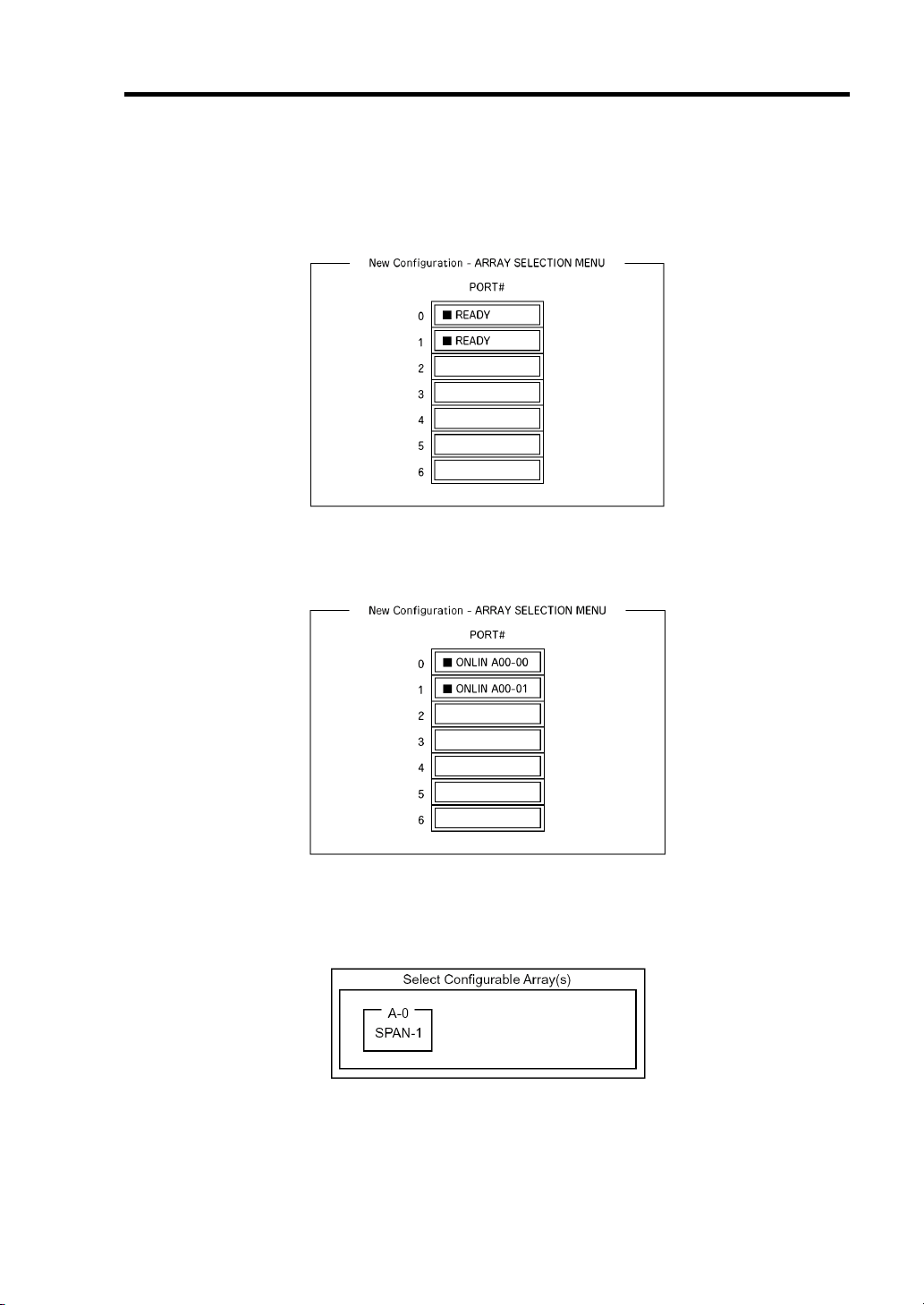
Configuring Your Server 4-33
3. When a confirmation message (Proceed?) is displayed, select [Yes.]
The SCAN DEVICE starts (scanning information is displayed at the bottom of the screen).
Upon completion of SCAN DEVICE, the [New Configuration - ARRAY SELECTION
MENU] screen appears.
4. Move the cursor onto the hard disk drive to be packed and then press Space to select the
hard disk drive.
The display for the selected hard disk drive changes from READY to ONLINE.
5. Press F10 to set [Select Configurable Array(s)].
6. Press Space.
SPAN-1 is set.
Page 84
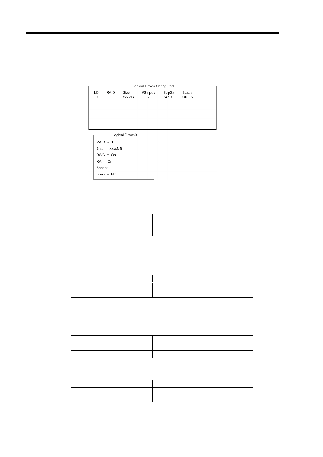
4-34 Configuring Your Server
7. Press F10 to create virtual drive.
The [Virtual Drives Configure] screen appears. (The figure below shows an example of
RAID1 configured with two hard disk drives.)
8. Select "RAID", "Size", "DWC", "RA", or "Span" by using cursor keys. Then press Enter
to fix the selection and set each value.
(1) "RAID": Sets RAID level.
Parameter Description
0RAID0
1RAID1
(2) "Size": Sets virtual drive size.
Up to 8 virtual drives can be created per RAID controller.
(3) "DWC": Sets parameter for Disk Write Cache.
Parameter Description
Off Write thru
On (Recommended) * Write back
* DWC is factory-set to "On" in consideration of performance. The data in cache
memory may be lost if an unexpected power failure occurs. If set to "Off", the
performance may be decreased to approximately 50% or less.
(4) "RA": Sets parameter for Read Ahead.
Parameter Description
Off Does not perform read ahead.
On (Recommended) Performs read ahead.
(5) "Span: Sets Span.
Parameter Description
SPAN=NO (Recommended) Does not perform SPAN.
SPAN=YES Performs SPAN.
* SPAN is not available since the CPU blade contains only two hard disk drives.
Page 85

Configuring Your Server 4-35
9. When all settings are completed, select "Accept" and then press Enter to create virtual
drive.
The created virtual drive is displayed in the [Virtual Drive Configured] screen.
10. After creating virtual drive, press Esc to exit from the menu.
Go back to the [Save Configuration?] screen and then select "Yes" to save the
configuration.
11. When the confirmation message shows that the configuration has been saved, press Esc
to return to the TOP menu screen.
12. On the TOP menu screen, select [Objects] → [Virtual Drive] → [View/Update
Parameters] to check virtual drive information.
13. Select [Initialize] in the TOP menu screen.
14. When the [Virtual Drives] screen appears, move the cursor to the virtual drive to be
initialized, and press Space.
The virtual drive is selected.
15. After selecting virtual drive, press F10 to start initialization.
A confirmation screen for execution appears. Select "Yes" to start initialization.
When the progress bar in the [Initialize Virtual Drive Progress] screen indicates 100%,
initialization is completed.
16. Execute Check Consistency on the virtual drive that has been initialized.
See [Check Consistency] for details.
17. Press Esc to return to the TOP menu and exit from LSI Software Configuration Utility.
IMPORTANT: Be sure to execute Check Consistency after creating
configuration. Inconsistency may be detected or corrected at the first
Check Consistency performed after the configuration has been created,
however, it is not a problem.
Page 86
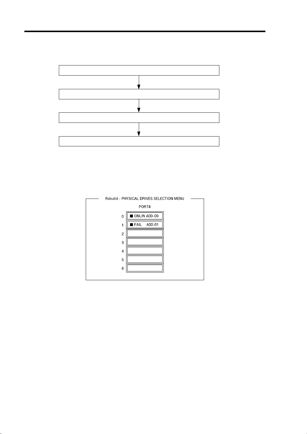
4-36 Configuring Your Server
Manual Rebuild
Replace hard disk drive
Run LSI Software Configuration Utility
Execute rebuilding
Exit LSI Software Configuration Utility
1. Replace a hard disk drive and turn on the CPU blade.
2. Run LSI Software Configuration Utility.
3. Select [Rebuild] from the TOP menu.
The [Rebuild – PHYSICAL DRIVES SELECTION MENU] screen appears.
4. Move the cursor onto the hard disk drive displaying "FAIL", and then press Space to
select it.
Multiple hard disk drives can be selected (simultaneous rebuilding.)
5. The "FAIL" indication for the hard disk drive selected starts blinking.
6. When hard disk drive has been selected, press F10 to start rebuilding.
7. When confirmation screen for execution appears. Select "Yes".
The rebuild process starts.
When the progress bar in the [Rebuild Physical Drives in Progress] screen indicates 100%,
rebuilding is completed.
8. Press Esc to return to the TOP menu and exit LSI Software Configuration Utility.
Page 87

Configuring Your Server 4-37
Check Consistency
Run LSI Software Configuration Utility
Execute Check Consistency
Exit LSI Software Configuration Utility
1. Run LSI Software Configuration Utility.
2. Select [Check Consistency] from the TOP menu.
The [Virtual Drives] screen appears.
3. Move the cursor onto the virtual drive to be checked, and press Space to select it.
4. When virtual drive has been selected, press F10 to start consistency check.
5. A confirmation screen for execution appears. Select "Yes".
The consistency check starts.
When the progress bar in the [Check Consistency Progress] screen indicates 100%, the
consistency check is completed.
6. Press Esc to return to the TOP menu and exit utility.
IMPORTANT: Be sure to execute Check Consistency after creating
configuration.
Page 88

4-38 Configuring Your Server
Others
Clear Configuration
1.
Clears configuration information. Select [Configure] → [Clear Configuration] from the
TOP menu. Executing [Clear Configuration] clears all configuration information on the
RAID controller and hard disk drives. The configuration information on all channels of
the RAID controller is also cleared.
NOTES:
LSI Software RAID Configuration Utility cannot delete each virtual
drive. Use Universal RAID Utility instead.
If the configuration information stored in RAID controller differs
from that in hard disk drive, configuration by using the
configuration information in RAID controller will fail. Perform
"Clear Configuration", then create a configuration again.
2. Force Online
Puts a hard disk drive being in the FAIL status online.
Select [Objects] → [Physical Drive] → (select hard disk drive) → [Force Online] from the
TOP menu.
3. Rebuild Rate
Sets the Rebuild Rate.
Select [Objects] → [Adapter] → [Sel. Adapter] → [Rebuild Rate] from the TOP menu.
Available value is between 0% and 100%. Default value (recommended) is 30%.
4. Hard disk drive information
Checks hard disk drive information.
Select [Objects] → [Physical Drive] → (select hard disk drive) → [View Drive
Information] from the TOP menu.
Page 89

Configuring Your Server 4-39
LSI Software Configuration Utility and Universal RAID Utility
You can use Universal RAID Utility for configuration and management, monitoring of N8403-027
SATA interface card / N8403-026 RAID cotnroller after start up operating system.
The point to keep in mind when you use Universal RAID Utility together with LSI Software
Configuration Utility is as follows.
Terms
LSI Software Configuration Utility and Universal RAID Utility are different in term. When you use
Universal RAID Utility together with LSI Software Configuration Utility, please convert terms by
the following list.
Term of LSI Software
Configuration Utility
Adapter RAID Controller RAID Controller
Virtual Drive Logical Drive Logical Drive
Array Disk Array Disk Array
Physical Drive Hard disk drive Hard disk drive
Term of Universal RAID Utility
RAID Viewer raidcmd
NOTE: raidcmd is a command that Universal RAID Utility provides.
For more information, refer to "Universal RAID Utility Ver2.0 User's
Guide".
Number and ID
The number to manage each component of RAID Controller used in the LSI Software Configuration
Utility is different from that in Universal RAID Utility, as shown in the table below. For more
information, refer to "Universal RAID Utility Ver2.0 User's Guide".
Management Number
Item
Adapter (RAID Controller) A number beginning with 0 A number beginning with 1
Virtual Drive (Logical Drive) A number beginning with 0 A number beginning with 1
Array (Disk Array) A number beginning with 0 A number beginning with 1
Physical Drive (Hard disk drive) A number beginning with 0 A number beginning with 1
LSI Software
Configuration Utility
Universal RAID Utility
Page 90

4-40 Configuring Your Server
Setting of Priority (Rate) of Background Tasks
LSI Software Configuration Utility displays and sets priority of background tasks (Rebuild, Patrol
Read, and Consistency Check) by percentage. Universal RAID Utility uses three levels as
High/Middle/Low for them. See the table below.
The priority indicates the ratio which the background task occupies to the process running by the
RAID Controller.
The setting value of LSI Software Configuration Utility and
the display level of Universal RAID Utility
Item
Rebuild Rate
Patrol Read Rate
Chk Const Rate
Setting value of LSI Software
Configuration Utility (%)
15 to 100 High
8 to 14 Middle
0 to 7 Low
15 to 100 High
8 to 14 Middle
0 to 7 Low
15 to 100 High
8 to 14 Middle
0 to 7 Low
Display level of Universal
RAID Utility
The setting level of Universal RAID Utility and the display level of
LSI Software Configuration Utility
Item
Rebuild Priority
Patrol Read Priority
Consistency Check
Priority
Setting level of Universal
RAID Utility
High 20
Middle 10
Low 5
High 20
Middle 10
Low 5
High 20
Middle 10
Low 5
Display level of LSI Software
Configuration Utility (%)
NOTES:
LSI Software Configuration Utility allows you to set BGI Rate
(Background Initialize Priority). But Universal RAID Utility does
not.
The server does not support full initialization feature, you cannot set
Initialization Priority though Universal RAID Utility allows it.
Page 91

Configuring Your Server 4-41
Configuration by N8403-026 RAID Controller
This section describes how to use the internal hard disk drives as RAID System by N8403-026
RAID Controller.
Rebuild
If a HDD is defected, the rebuild feature can recover the data in the defected HDD. The rebuild can
be applied to redundant virtual drives in the RAID1 level.
Manual Rebuild
The manual rebuild can be performed by using Universal RAID Utility, the management utility of
the RAID Controller. Select a HDD and start the rebuild manually.
For the detailed operation, refer to the "Universal RAID Utility
EXPRESSBUILDER DVD that comes with the server.
Auto Rebuild
Ver2.0 User's Guide" in NEC
The RAID Controller can automatically start the rebuild without use of any utility such as Universal
RAID Utility.
The auto rebuild includes the following type:
Hot-swap rebuild
Automatic rebuild by hot-swapping defected HDD.
IMPORTANT: Note the following for the rebuild:
The HDD used for rebuild should have the same capacity, rotation
speed, and standard as the defected HDD.
During rebuild, the processing rate is decreased due to much load.
During rebuild, do not shutdown or reboot the server. If the server is
shutdown by an unforeseen accident such as power interruption,
turn on the power again as soon as possible. The rebuild is
automatically restarted.
The interval from the removal of the defected HDD to the
installation of a substitute HDD should be 60 sec or longer.
If the hot-swap rebuild does not operate, perform the manual
rebuild.
Page 92

4-42 Configuring Your Server
Patrol Read
The patrol read gives the read & verify test in the entire area of HDDs. It can be performed for all
HDDs assigned to virtual drives.
The Patrol Read allows subsequent detects of HDDs to be detected and repaired.
For HDDs configuring redundant virtual drives, error sectors detected during Patrol Read can be
repaired.
IMPORTANT: Note the following for the patrol read:
For the RAID Controller, Patrol Read feature is factory-set to
"Enabled".
To change settings of Patrol Read, use Universal RAID Utility.
If the system is restarted while running Patrol Read, Patrol Read
resumes from that point.
Consistency Check
The Consistency Check is used to check consistency among virtual drives. It is available for
redundant virtual drives except for RAID0. It is also available for host spare.
Consistency Check can be performed through WebBIOS or Universal RAID Utility.
Consistency Check performs not only consistency check but also repair of error sectors.
Accordingly, it can be used as preventive maintenance.
IMPORTANT: Note the following for Consistency Check:
During Consistency Check, the processing rate is decreased due to
much load.
If the system is restarted, the Consistency Check is aborted.
However, the Consistency Check resumes after restart.
To schedule execution of Consistency Check, use WebBIOS, not the
Universal RAID Utility
Page 93

Configuring Your Server 4-43
Reconstruction
The reconstruction feature is used to change configuration and/or RAID level of existing virtual
drive. The Reconstruction contains the following three features, however, the RAID Controller
supports "Migration with addition" only.
IMPORTANT: You can use WebBIOS for Reconstruction. Universal
RAID Utility does not support Reconstruction.
Removed physical drive
Unsupported.
Migration only
Unsupported.
Migration with addition
Use this feature to add HDDs to existing virtual drive. The execution patterns are as shown below
(α: Number of HDDs to be added).
Before execution After execution
RAID
level
RAID0 x RAID0
RAID0 1 RAID1 2 Capacity remains unchanged.
RAID1 2 RAID0
Number of
HDDs
RAID
level
Number of
HDDs
x+α Capacity increased: equivalent to α HDDs
2+α Capacity increased: equivalent to α+1 HDDs
Description
Page 94
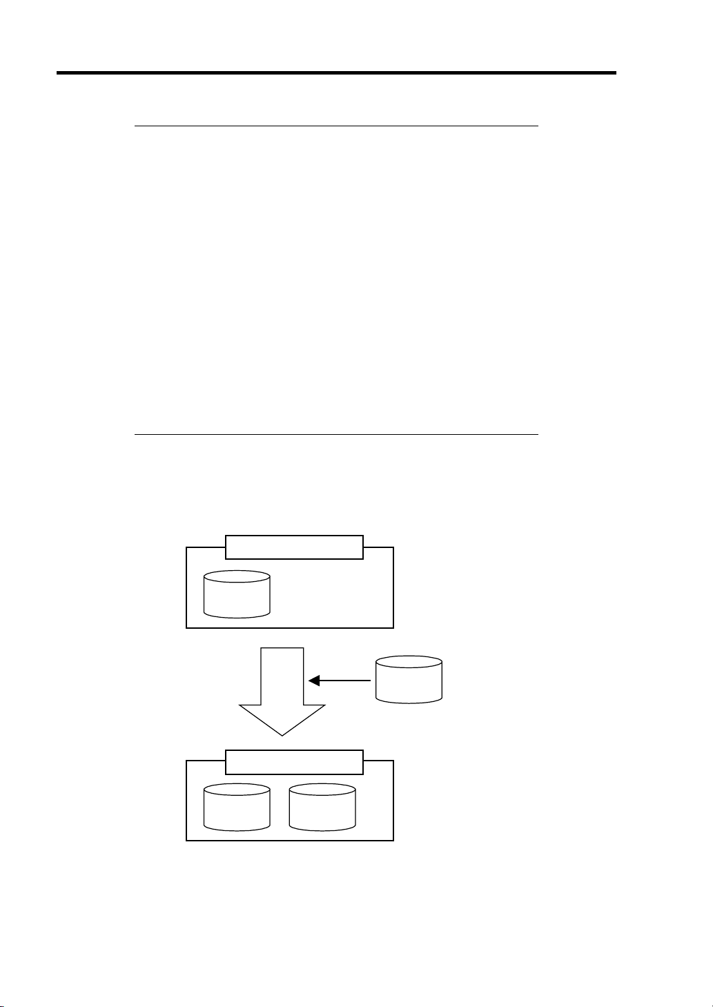
4-44 Configuring Your Server
IMPORTANT: Note the following for the Reconstruction:
Be sure to make backup copy of data and perform Consistency
Check before starting Reconstruction.
The Reconstruction is disabled in the configuration where several
virtual drives are defined in one disk group
During Reconstruction, the processing rate is decreased due to much
load.
The Reconstruction may be performed for the degraded or partially
degraded virtual drive. However, it is recommended to execute
Rebuild to recover the virtual drive, then execute Reconstruction.
During Reconstruction, do not shutdown or reboot the server. If the
server is shutdown by an unforeseen accident such as power
interruption, turn on the power again as soon as possible. The
Reconstruction is automatically restarted.
In some configuration, Background Initialize may start
automatically upon completion of Reconstruction.
Ex: Migration with addition for RAID0 virtual drive
The figure below shows an example of adding a single 36GB HDD to a RAID0 virtual drive
configured with a single 36GB HDD to make data redundancy available.
Virtual drive (RAID0)
[Before execution]
36GB
Execute Migration with addition
Virtual drive (RAID0)
36GB 36GB
Capacity = 36GB
36GB
[After execution]
Capacity = 72GB
Page 95

Configuring Your Server 4-45
Before Using WebBIOS
Read the following sections describing supported functions and precautions before using
"WebBIOS".
Supported Functions
Indication of model name and capacity of hard disk drive
Indication of allocation status of hard disk drive
Creation of virtual drive
– Setting of RAID level
– Setting of Stripe Block size
– Setting of Read Policy/Write Policy/IO Policy
Indication of configuration information and status of virtual drive
Removal of virtual drive
Clearing of configuration
Execution of initialization
Execution of Consistency Check
Execution of manual rebuild
Execution of reconstruction
Page 96
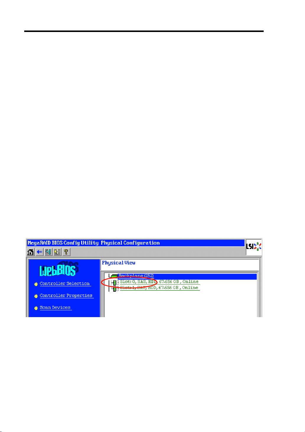
4-46 Configuring Your Server
Notes on Creating Virtual Drive
The hard disk drives configuring the drive group should have the same capacity and
1.
rotation speed.
2. Be sure to execute Consistency Check after creating VD.
3. When installing an OS in VD under N8403-026 RAID controller, create a VD dedicated to
OS installation.
4. WebBIOS cannot be handled via remote console functions of NEC ESMPRO Manager.
5. The physical drive numbers shown in WebBIOS and those shown in Universal RAID
Utility are identified as follows.
– WebBIOS
Slot number shown in Physical View *
*1: The slot number, type of hard disk drive, its capacity, and its current status are
shown in Physical View.
The slot number is indicated by the number 0 or 1. It represents the slot number in
the hard disk drive.
– Universal RAID Utility
ID shown in Hard disk drive Properties
The slot number shown on WebBIOS corresponds to the hard disk drive ID shown
on Universal RAID Utility. For more information, refer to the Universal RAID
Utility Ver2.0 User's Guide.
Physical View of WebBIOS
Page 97
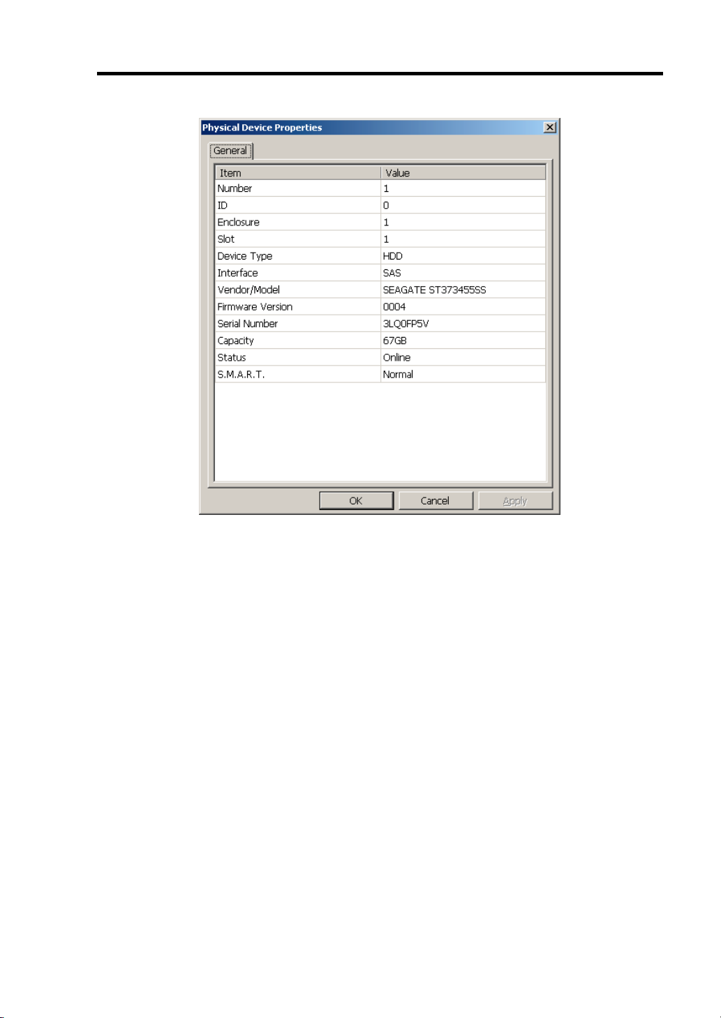
Configuring Your Server 4-47
Property of Hard disk drive of Universal RAID Utility
Page 98

4-48 Configuring Your Server
Using WebBIOS
Starting WebBIOS
When the screen as shown below appears, press Ctrl + H to start WebBIOS.
1.
LSI MegaRAID SAS - MFI BIOS
Version XXXX (Build MMM DD, YYYY)
Copyright (c) 20XX LSI Corporation
HA - X (Bus X Dev X) MegaRAID SAS 8708EM2
FW package: X.X.X - XXXX
0 Virtual Drive(s) found on the host adapter.
0 Virtual Drive(s) handled by BIOS.
Press <Ctrl> <H> for WebBIOS......
POST screen image (with no virtual drive assigned)
IMPORTANT:
Do not press unnecessary key such as Pause during POST.
If you fail to press Ctrl + H or the system proceeds without
displaying the WebBIOS main menu (shown on the next page),
reboot the system, and press Ctrl + H on POST screen.
Page 99
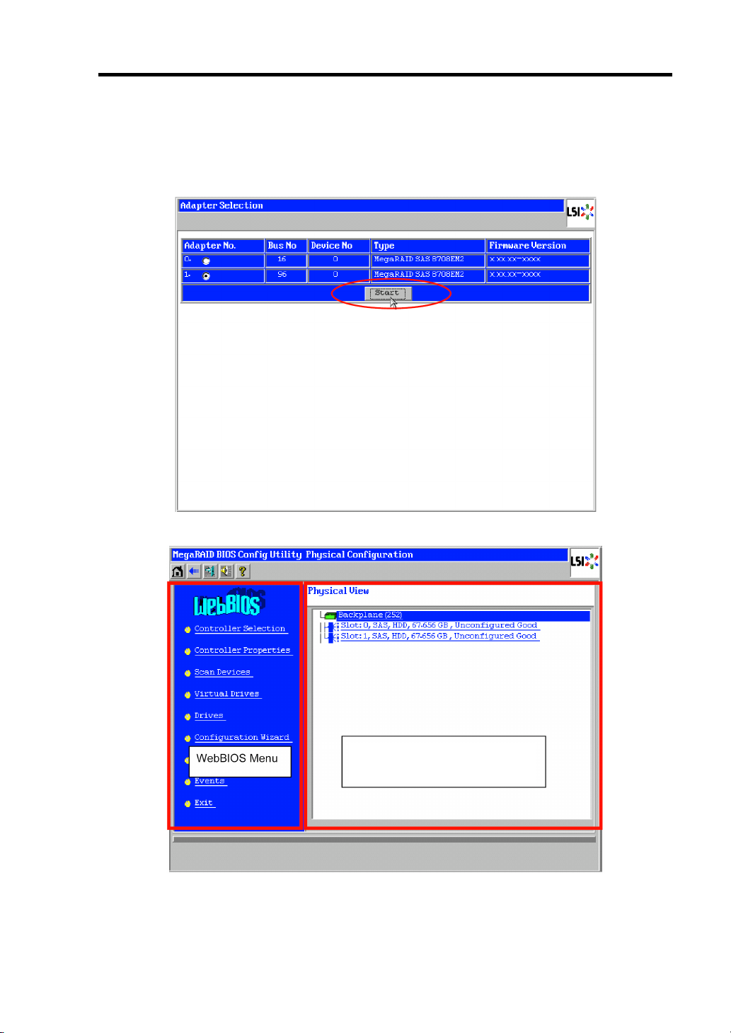
Configuring Your Server 4-49
Main Menu
Shown below is [Adapter Selection] screen that appears first on WebBIOS. On [Adapter No.] box,
select an adapter you want to operate with WebBIOS, then click [Start].
When the adapter is selected on [Adapter Selection], the WebBIOS Top Menu appears.
Information of VD configured and
hard disk drives connected with the
controller.
Page 100

4-50 Configuring Your Server
Controller Selection: Goes back to Adapter Selection menu.
Controller Properties: Displays properties of the controller.
Scan Devices: Detects hard disk drives connected with the controller again.
Virtual Drives: Opens operation window for VD that has already been
Drives: Opens operation window for hard disk drive connected with the
Configuration Wizard: Displays the wizard to configure VD.
Physical View /
Logical View:
Events: Displays event data.
Exit: Goes to Exit menu of WebBIOS.
Status Indication of Virtual Drive (not shown on Physical View)
Optimal: Indicates that the VD is in normal state.
Degraded: Indicates that one of the hard disk drives in the relevant VD is
Offline: The relevant VD is in offline state.
Initialization: The relevant VD is being initialized.
ConsistencyCheck: Consistency Check is being performed to the relevant VD.
Rebuild: The relevant VD is being rebuilt.
Reconstruction: The relevant VD is being reconstructed.
WebBIOS Menu
configured.
controller.
Switches indication between hard disk drives and VD
configuration.
The indication is green.
degraded.
The indication is blue.
The indication is red.
Status Indication of Hard disk drive
Reconstruction: The relevant VD is being reconstructed.
Unconfigured Good: The hard disk drive connected with the controller is not in use.
The indication is blue.
Online: Indicates that the hard disk drive in configuration is in normal state.
The indication is green.
Offline: Indicates that the hard disk drive in configuration is in offline state.
The indication is red.
Unconfigured Bad: The relevant hard disk drive is faulty.
(The hard disk drive in this status can be checked only on Physical
View.)
The indication is black.
Rebuild The relevant hard disk drive is being rebuilt.
The indication is yellow.
Hotspare Indicates the hard disk drive that is assigned to hot-spare.
The indication is pink.
 Loading...