

Page 1
N8151-54
内蔵
AIT
Built-In AIT
取扱説明書 ......................1ページ
User’s Guide
...............
Page 60
製品をご使用になる前に必ず本書をお読みください。本書
•
は熟読の上、大切に保管してください。
• Make sure you read this manual before using the
product.
store it in a safe place.
After reading this manual carefully,
2-586-887-01(1)
Page 2
商標について
Microsoft
標です。
Advanced Intelligent Tape
記載の会社名および商品名は各社の商標または登録商標です。
Windows 2000は、Microsoft® Windows® 2000 Professional operating system、Microsoft® Windows
ating system
とそのロゴ、および
®
2000 Server operating system
の略称です。
Windows
はソニー株式会社の商標です。
は米国
Microsoft Corporation
、および
Microsoft® Windows® 2000 Advanced Server oper-
の米国およびその他の国における登録商
Windows XPは、Microsoft® Windows® XP Professional operating system
®
XP Home Edition operating system
dows
の略称です。
、および
Microsoft® Win-
Windows Server 2003は、Microsoft® Windows Server™ 2003 Standard Edition operating system
Microsoft® Windows Server™ 2003 Enterprise Edition operating system、Microsoft® Windows
、および
Server™ 2003 Datacenter Edition operating system
Web Edition operating system
サンプルアプリケーションで使用している名称は、すべて架空のものです。実在する品名、団体名、個人名とは一
切関係ありません。
Für kunden in Deutshland
Diese Ausrüstung erfüllt die Europäischen EMC-Bestimmungen für die Verwendung in folgender / folgenden Umgebung(en):
• Wohngegenden
• Gewerbegebiete
• Leichtindustriegebiete
(Diese Ausrüstung erfüllt die Bestimmungen der Norm EN55022, Klasse B.)
の略称です。
Microsoft® Windows Server™ 2003
、
ご注意
(1) 本書の内容の一部または全部を無断転載することは禁止されています。
(2) 本書の内容に関しては将来予告なしに変更することがあります。
(3)
(4) 本書は内容について万全を期して作成いたしましたが、万一ご不審な点や誤り、記載もれなどお気づきのこ
(5)運用した結果の影響については(4)項にかかわらず責任を負いかねますのでご了承ください。
の許可なく複製・改変などを行うことはできません。
NEC
とがありましたら、お買い求めの販売店にご連絡ください。
©
NEC Corporation 2005
1
Page 3
この取扱説明書は、必要なときすぐに参照できるよう、お手元に置いておくようにし
てください。「使用上のご注意」を必ずお読みください。
使用上のご注意
本製品を安全に正しくご使用になるために必要な情報が記載されています。
〜必ずお読みください〜
安全にかかわる表示について
本書にはどこが危険か、どのような危険に遭うのか、どうすれば危険を避けられるかなど
について説明されています。
本書、および警告ラベルでは危険の程度を表す言葉として、「警告」と「注意」という用語を
使用しています。それぞれの用語は次のような意味を持つものとして定義されます。
警告
注意
危険に対する注意・表示は次の
のような意味を持つものとして定義されています。
人が死亡する、または重傷を負うおそれがあることを示します。
火傷やけがなどを負うおそれや物的損害を負うおそれがあることを示
します。
種類の記号を使って表しています。それぞれの記号は次
3
注意の喚起 この記号は危険が発生するおそれがあることを表
します。記号の中の絵表示は危険の内容を図案化
したものです。
(例)
(感電注意)
使用上のご注意
2
行為の禁止 この記号は行為の禁止を表します。記号の中や近
くの絵表示は、してはならない行為の内容を図案
化したものです。
行為の強制 この記号は行為の強制を表します。記号の中の絵
表示は、しなければならない行為の内容を図案化
したものです。危険を避けるためにはこの行為が
必要です。
(例)
(分解禁止)
(例)
(プラグを抜け)
Page 4
(本書での表示例)
注意を促す記号 危険に対する注意の内容 危険の程度を表す用語
注意
電源が
本体装置への取り付け・取り外しの際や、周辺機器との接続の際は
必ず主電源に接続しているACコードをコンセントから抜いてくだ
さい。
しや接続をすると感電をするおそれがあります。
のまま取り付け・取り外しをしない
ON
コードがコンセントに接続されたまま取り付け・取り外
AC
本書および警告ラベルで使用する記号とその内容
注意の喚起
感電のおそれがあることを示し
ます。
指などがはさまれるおそれがあ
ることを示します。
高温による障害を負うおそれが
あることを示します。
行為の禁止
特定しない一般的な禁止を示し
ます。
発煙または発火のおそれがある
ことを示します。
特定しない一般的な注意・警告
を示します。
本製品を分解・修理・改造しな
いでください。感電や火災のお
それがあります。
行為の強制
本製品の電源プラグをコンセン
トから抜いてください。火災や
感電のおそれがあります。
特定しない一般的な使用者の行
為を指示します。説明に従った
操作をしてください。
使用上のご注意
3
Page 5
安全上のご注意
本製品を安全にお使いいただくために、ここで説明する注意事項をよく読んでご理解し、
安全にご活用ください。記号の説明については巻頭の『安全にかかわる表示について』の説
明を参照してください。
全般的な注意事項
警告
人命に関わる業務や高度な信頼性を必要とする業務には使用しない
本製品は、医療機器・原子力設備や機器、航空宇宙機器・輸送設備
や機器など、人命に関わる設備や機器および高度な信頼性を必要と
する設備や機器などへの組み込みやこれらの機器の制御を目的とし
た使用は意図されておりません。これらの設備や機器、制御システ
ムなどに本製品を使用した結果、人身事故、財産被害などが生じて
も当社はいかなる責任も負いかねます。
煙や異臭、異音がしたまま使用しない
万一、煙、異臭、異音などが生じた場合は、ただちに本体装置の電
源を
ブルを抜いてください。その後、お買い求めの販売店または保守
サービス会社にご連絡ください。そのまま使用すると火災の原因と
なります。
にしてACコードをコンセントから抜き、本製品のDCケー
OFF
使用上のご注意
4
針金や金属片を差し込まない
通気孔やカートリッジ挿入口から金属片や針金などの異物を差し込
まないでください。感電の危険があります。
注意
製品内に水や異物を入れない
製品内に水などの液体、ピンやクリップなどの異物を入れないでく
ださい。火災や感電、故障の原因となります。もし入ってしまった
ときは、すぐに本体装置の電源を
から抜き、本製品の
売店または保守サービス会社に連絡してください。
ケーブルを抜いてください。分解しないで販
DC
にしてACコードをコンセント
OFF
Page 6
電源・ACコードに関する注意事項
ぬれた手でDCケーブルを持たない
警告
ぬれた手で
それがあります。
ケーブルの抜き差しをしないでください。感電するお
DC
注意
電源がONのまま取り付け・取り外しをしない
本体装置への取り付け・取り外しの際や、周辺機器との接続の際は
必ず主電源に接続している
い。
接続をすると感電をするおそれがあります。
中途半端に差し込まない
DC
と接触不良のため発熱し、火災の原因となることがあります。また
差し込み部にほこりがたまり、水滴などが付くと発熱し、火災の原
因となるおそれがあります。
指定以外の接続をしない
DC
い。指定以外の接続や配線は火災や感電の原因となるおそれがあり
ます。
コードがコンセントに接続されたまま取り付け・取り外しや
AC
ケーブルはしっかりと差し込んでください。中途半端に差し込む
ケーブルの接続や配線は本書の説明に従って正しく行ってくださ
コードをコンセントから抜いてくださ
AC
破損したケーブルを使用しない
ケーブルを接続する前にコネクタが破損していたり、コネクタピン
が曲がっていたり、汚れたりしていないことを確認してください。
破損や曲がっているコネクタおよび汚れたコネクタを使用すると
ショートにより火災を引き起こすおそれがあります。
指定以外のケーブルを使用しない
本体装置と接続するケーブルは当社指定のものを使用し、接続先を
よく確認してください。指定以外のケーブルを使用したり、指示と
は異なる接続のまま使用したりすると火災を引き起こすおそれがあ
ります。
使用上のご注意
5
Page 7
設置・移動・保管・接続に関する注意事項
注意
通気孔をふさがない
本製品の前面にある通気孔をふさがないでください。内部の温度が上昇
し、誤動作の原因となるばかりでなく、火災や感電の原因となります。
プラグを差し込んだままインタフェースケーブルの取り付けや取り
外しをしない
インタフェースケーブルの取り付け/取り外しは本体装置の
ドをコンセントから抜いて行ってください。たとえ電源を
ても
り、ショートによる火災を起こしたりすることがあります。
指定以外のインタフェースケーブルを使用しない
インタフェースケーブルは、
る製品やコネクタを確認した上で接続してください。指定以外の
ケーブルを使用したり、接続先を誤ったりすると、ショートにより
火災を起こすことがあります。
また、インタフェースケーブルの取り扱いや接続について次の注意
をお守りください。
•
•
•
•
•
•
腐食性ガスの存在する環境で使用または保管しない
腐食性ガス(二酸化硫黄、硫化水素、二酸化窒素、塩素、アンモニ
ア、オゾンなど)の存在する環境に設置し、使用しないでください。
また、ほこりや空気中に腐食を促進する成分(塩化ナトリウムや硫黄
など)や導電性の金属などが含まれている環境へも設置しないでくだ
さい。製品内部のプリント板が腐食し、故障および発煙・発火の原
因となるおそれがあります。
もしご使用の環境で上記の疑いがある場合は、販売店または保守
サービス会社にご相談ください。
コードを接続したままケーブルやコネクタに触ると感電した
AC
が指定するものを使用し、接続す
NEC
ケーブルを踏まない。
ケーブルの上にものを載せない。
ケーブルの接続がゆるんだまま使用しない。
破損したケーブルを使用しない。
破損したケーブルコネクタを使用しない。
ネジ止めなどのロックを確実に行ってください。
AC
OFF
コー
にし
使用上のご注意
6
Page 8
高温注意
注意
本体装置の電源を
はじめ装置内の部品が高温になっています。十分に冷めたことを確
認してから取り付け/取り外しを行ってください。
お手入れに関する注意事項
自分で分解・修理・改造はしない
本製品の分解や、修理・改造は絶対にしないでください。製品が正
常に動作しなくなるばかりでなく、感電や火災の危険があります。
本製品でお客様が行える分解は次の作業のみです。
次に記述する以外の分解は絶対にしないでください。
ブラケットの取り外し/取り付け
•
・信号ケーブルの取り付け/取り外し
•DC
プラグを差し込んだまま取り扱わない
お手入れは、本体装置の電源を
から抜き、本製品の
にしても、ACコードを接続したまま製品内の部品に触ると感電
OFF
するおそれがあります。
した直後は、内蔵型のハードディスクなどを
OFF
警告
にして、ACコードをコンセント
OFF
ケーブルを抜いてください。たとえ電源を
DC
注意
中途半端に取り付けない
ケーブルやインタフェースケーブルは確実に取り付けてくださ
DC
い。中途半端に取り付けると接触不良を起こし、発煙や発火の原因
となるおそれがあります。
使用上のご注意
7
Page 9
運用中の注意事項
注意
カートリッジ挿入口に手を入れない
カートリッジ挿入口に手を入れないでください。手を挟まれたり、
巻き込まれたりしてけがをするおそれがあります。
雷がなったら触らない
雷が鳴りだしたら、本製品内蔵の本体装置には、触れないでくださ
い。感電の原因となります。
ペットを近づけない
本製品にペットなどの生き物を近づけないでください。排泄物や体
毛が製品内部に入って火災や感電の原因となります。
近くで携帯電話や
本製品のそばでは携帯電話や
しておいてください。電波による誤動作の原因となります。
、ポケットベルを使わない
PHS
、ポケットベルの電源を
PHS
OFF
に
使用上のご注意
8
Page 10

正しく動作させるために
本製品を正しく動作させるために、次の点について注意してください。
データカートリッジの取り扱いに関する注意事項については、「
AIT
ジ」の章を参照してください。
AIT
データカートリッ
● 本製品の
ください。
→ 誤動作の原因となります。
● 本製品前面にある
OFF
→ 故障、およびバックアップデータの破損の原因となります。
● 腐食性ガスの発生する場所、薬品類の近くや薬品類がかかるおそれのある場所に保
管しないでください。
→ 部品が変形したり傷んだりして正常に動作しなくなるおそれがあります。
● 強い振動の発生する場所に保管しないでください。
→ 故障の原因となります。
● 本製品にセットするデータカートリッジには、当社製の「
(EF型番品)を使用してください。
→ 当社製以外のデータカートリッジを使用するとリード/ライトエラーを起こす
● 定期的にクリーニングを実施してください。
→ クリーニングについては、「クリーニング」(
●本製品のクリーニングには、当社製の「
(型番
→ 当社製以外のクリーナーを使用すると故障の原因となることがあります。
● カートリッジを入れたままでの移動はやめてください。
→ 衝撃が加わったとき、製品やカートリッジを傷める原因となります。
● バックアップ完了後は、カートリッジを取り出してください。
→ カートリッジの寿命が短くなったり、誤動作の原因となるおそれがあります。
SCSI ID
にしないでください。
ことがあります。
: EF-3237J
とその他の
SCSI
機器の
TAPE MOTION LED
AIT
)」を使用してください。
SCSI ID
が点滅しているときに本体装置の電源を
クリーニングカートリッジ
が重複しないように設定して
データカートリッジ」
AIT
ページ)を参照してください。
43
使用上のご注意
9
Page 11

本書について
本書は、
きです。内蔵
たときにご利用ください。
本書は、内蔵
いおよび保守)と内蔵
使いになるための事柄(取り扱い方法や保管方法)の
N8151-54 内蔵AIT
のセットアップを行う場合や日常使用する上で、わからないことが起き
AIT
を安全に、正しくお使いになるための事柄(セットアップや日常の取り扱
AIT
AIT
を正しくセットアップし、使用できるようにするための手引
で使用できるカートリッジ「
データカートリッジ」を正しくお
AIT
つの章から構成されています。
2
はじめて取り扱うときの読み方
本製品を梱包箱から取り出して、はじめて取り扱うときは次の順序で本書を参照して、
セットアップをしてください。
箱の中身を確認する ............................... 箱の中身について(→13ページ)
1.
取り扱う上での注意事項を覚える ......... 使用上のご注意(→2〜8ページ)
2.
内蔵
3.
取り付け前の設定をする ........................ セットアップ(→19〜24ページ)
4.
本体装置に取り付ける ........................... セットアップ(→25〜28ページ)
5.
ドライバをインストールする*............... テープドライバのインストール
6.
カートリッジの取り扱い方法を覚える ..
7.
カートリッジをセットする .................... 取り扱い(→39〜42ページ)
8.
9. LED
内蔵
10.
の部品の名前を覚える .............. 各部の名称と機能(→17〜19ページ)
AIT
(→
29〜37
データカートリッジ(EF型番品)に
AIT
ついて(→
表示を確認する .............................. 取り扱い(→42ページ)
をクリーニングする ................. クリーニング(→43〜44ページ)
AIT
ページ)
45〜50
ページ)
*
データの保存のしかたやデータの保存形式などの設定については、バッ
クアップソフトに添付の説明書を参照してください。
使用上のご注意
10
Windows 2000のWindows
および
Windows Server 2003
バックアップ、
のバックアップを使用する場合のみ
Windows XP
のバックアップ、
Page 12
本文中の記号について
本文中では、次の記号を使って運用上の注意やヒントを示しています(安全上の注意事項
に関する記号については巻頭の説明をご覧ください)。
製品の取り扱いや、ソフトウェアの操作で守らなければならない事柄や
特に注意をすべき点を示します。
知っておくと役に立つ情報や、便利なことなどを示します。
✎
その他
第三者への譲渡について
本製品または本製品に添付されているものを第三者に譲渡(または売却)するときは、次の
注意を守ってください。
●本製品本体について
本製品を第三者へ譲渡(または売却)する場合は、本書を一緒にお渡しください。
●その他の付属品について
その他の付属品もセットアップするときなどに必要となりますので、一緒にお渡し
ください。
テープ内のデータについて
使用していたテープに保存されている大切なデータ(例えば経営情報や企業の経理情報な
ど)が第三者へ漏洩することのないように、お客様の責任において確実に処分しておいて
ください。
このようなトラブルを回避するために使用しているバックアップソフトでデータを完全
消去し、確実にデータを処分することを強くおすすめします。データの消去についての
詳細はバックアップソフトの取扱説明書をご参照ください。
なお、データの処分をしないまま譲渡(または売却)し、大切なデータが漏洩された場
合、その責任は負いかねます。
使用上のご注意
11
Page 13

●添付ソフトウェアについて
本製品に添付のソフトウェアを第三者に譲渡(売却)する場合には、以下の条件を満
たす必要があります。
添付されているすべてのものを譲渡し、譲渡した側は一切の複製物を保持しないこと。
各ソフトウェアに添付されている「ソフトウェアのご使用条件」の譲渡、移転に関す
る条件を満たすこと。
消耗品・製品の廃棄について
本製品、およびカートリッジの廃棄については各自治体の廃棄ルールに従ってください。
詳しくは、各自治体へお問い合わせください。
製品寿命について
本製品の製品寿命は5年です。
保証について
本製品には『保証書』が添付されています。『保証書』は販売店で所定事項を記入してお渡し
しますので、記載内容を確認のうえ、大切に保管してください。保証期間中に故障が発生
した場合は、『保証書』の記載内容にもとづき無料修理いたします。詳しくは『保証書』をご
覧ください。
保証期間後の修理についてはお買い求めの販売店、最寄りの
ビス会社に連絡してください。
本製品に対し保守契約を結ばれたお客様へ
本製品の保守停止時期は、製造打ち切り後5年になります。
使用上のご注意
12
NEC
または
NEC
の保守サー
Page 14
箱の中身について
N8151-54 内蔵AIT
の梱包箱の中には、内蔵
本体以外にいろいろな付属品が入ってい
AIT
ます。下図を参照してすべてがそろっていることを確認し、それぞれ点検してください。
万一足りないものや損傷しているものがある場合は、販売店に連絡してください。
□
N8151-54
□
CD-ROM
(取扱説明書、デバイスドライバ)
□ 保証書
□
□ クリーニング
カートリッジ
製品
AIT
取り扱いについて
ブラケット(
出荷しています。
□ネジ(4本)
※ 本製品を本体装置に
取り付けるときのみ
に使用します。
□ スタートアップガイド
本)をネジ止め(4本)した状態で
2
□
ケーブル
SCSI
※ オプションの
(
N8103-75
置を接続する場合に使用
SCSI
)を使用して本装
ボード
● 梱包箱や箱の中に入っていた固定用部材は、本製品を取り外して輸送する際に必要と
なります。大切に保管しておいてください。
● 接続する環境によっては使用しない部品がありますが、環境が変わったときなどに使
用する可能性がありますので、大切に保管してください。
● 添付の
CD-ROM
のバックアップをとってください。また、添付の
CD-ROM
をマス
タディスクとして大切に保管し、バックアップディスクを使用してください。
● 添付の保証書はアフターサービスを受けるときに必要となります。大切に保管してお
いてください。
使用上のご注意
13
Page 15
目 次
使用上のご注意
〜必ずお読みください〜
内蔵
AIT
について
商標について .............................................................
安全にかかわる表示について ...................................
本書および警告ラベルで使用する記号とその内容 ...
安全上のご注意 .........................................................
正しく動作させるために...........................................
本書について ..........................................................
はじめて取り扱うときの読み方 .................
本文中の記号について ................................
その他.....................................................................
第三者への譲渡について ............................
消耗品・製品の廃棄について .....................
製品寿命について .......................................
保証について ..............................................
箱の中身について ..................................................
特長 ........................................................................
使用可能カートリッジおよび互換表 .....................
各部の名称と機能 ..................................................
製品前面 ......................................................
製品前面(防塵カバーが開いているとき)...
製品背面 ......................................................
製品底面 ......................................................
セットアップ ..........................................................
ブラケットの取り外し、取り付け方法 ......
内蔵
〜ジャンパピンを使った設定〜 ..............
内蔵
〜
本体装置への取り付け ................................
バックアップソフト使用のご注意 ..............
テープデバイスドライバのインストール ...
機能を使用する場合 .......................................
ASR
取り扱い .................................................................
AIT
AIT
LED
データのリード/ライト ............................
の設定
AIT
の設定
AIT
スイッチを使った設定〜 ..............
DIP
データカートリッジのセット ...............
データカートリッジの取り出し ...........
表示 .....................................................
1
2
3
4
9
10
10
11
11
11
12
12
12
13
16
17
17
18
18
18
19
19
19
21
23
25
28
29
38
39
39
41
42
42
14
目 次
Page 16

クリーニング ..........................................................
リード/ライトヘッドのクリーニング ......
本体のクリーニング ...................................
43
43
44
データカートリッジ
AIT
(EF型番品)について
データカートリッジの各部の名称 .........................
使用・保管・運搬条件 ...........................................
ラベル .....................................................................
ラベル貼り付け位置 ...................................
ラベルへの記入上の注意事項 .....................
ライトプロテクト ..................................................
取り扱い上の注意事項 ...........................................
使用上のご注意 ...........................................
一般的注意事項 ...........................................
使用禁止基準 ..........................................................
寿命 ........................................................................
重要なデータの保存について ................................
データの3世代管理について..................................
データカートリッジの保管について .....................
バックアップと惨事復旧手順の制定 .....................
仕 様 .....................................................................
運用状況お客様記入シート ....................................
トラブルシューティング チェックリスト .............
45
46
46
46
47
47
48
48
48
49
49
50
50
50
50
51
53
54
目 次
15
Page 17
内蔵
本製品のセットアップから取り付け、日常の取り扱い方法について説明します。
AIT
について
特長
本製品には、次のような特長があります。
●
Advanced Intelligent Tape (AIT)
リッジに大容量記録できます。
●
データ圧縮機能により、次の容量をデータカートリッジに記録できます。
フォーマットを使ってデータをデータカート
規格
AIT-1 Turbo EF-2429
AIT-1 EF-2420L
AIT-2 Turbo EF-2431
AIT-2 EF-2423
●
データカートリッジに記録されているデータが圧縮されているのか、されていな
AIT
いのかを自動判別しますので、従来の機器で記録した
タも、そのまま読み出すことができます。
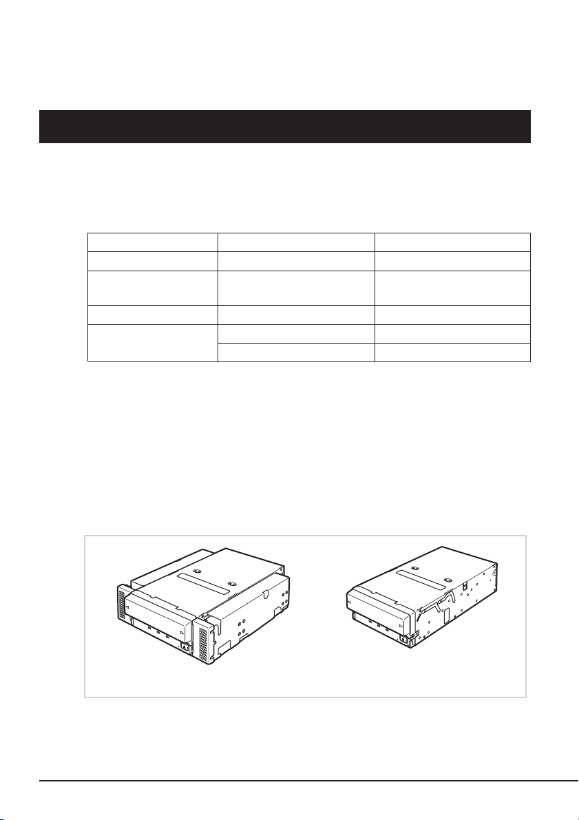
● 出荷時は、ドライブ部の両端にブラケットが取り付けられている
スですが、ブラケットを取り外すことにより、ドライブのみの
なります。
カートリッジ(型番) 記憶容量(
AIT
EF-2420
EF-2423S
データカートリッジのデー
AIT
3.5
5.25
インチデバイスに
約
80 Gbyte
約
70 Gbyte
約
50 Gbyte
約
160 Gbyte
約
100 Gbyte
約
72 Gbyte
インチデバイ
Gbyte
)
16
内蔵
AIT
インチデバイス実装タイプ(出荷時)
5.25
について
インチデバイス実装タイプ
3.5
Page 18
使用可能カートリッジおよび互換表
本製品には、当社製
データカートリッジを使用するとリード/ライトエラーの原因となる場合がありま
AIT
す。
●
本製品の
AIT
AIT-2 Turbo EF-2431
AIT-2 EF-2423
AIT-1 Turbo EF-2429
AIT-1 EF-2420L
データカートリッジ(EF型番品)をご使用ください。当社製以外の
AIT
カートリッジの互換は、下記の通りです。
規格 型番 読み取り 書き込み テープ長
○○
EF-2423S 170 m
EF-2420 170 m
○○
○○
○○
186 m
230 m
186 m
230 m
各部の名称と機能
本製品の各部の名称と機能について説明します。
インチデバイスベイ実装タイプと
5.25
み)の、各部の名称と働きおよび設定方法は、共通です。(以降、本書では、
デバイスの図を使用して説明します。)
インチデバイスベイ実装タイプ(ドライブ部の
3.5
5.25
インチ
内蔵
AIT
について
17
Page 19
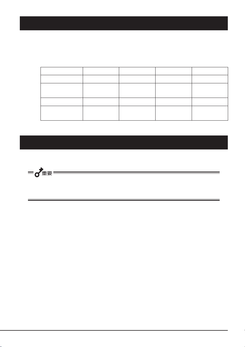
製品前面
1
654 3
7
2
製品前面(防塵カバーが開いているとき)
8
1
1 防塵カバー
カートリッジ挿入口を保護するカバー(→
ページ)。
2 通風口
(ドライブ部には通風口はありません。)
3
4
5
6
7 ブラケット
8 カートリッジ挿入口
ボタン
EJECT
データカートリッジを本製品から取り出
AIT
すときに押す(→41ページ)。
REPLACE TAPE LED
データカートリッジの交換を示す
AIT
(→42ページ)。
CLEANING REQUEST LED
データカートリッジのクリーニングを
AIT
示す
LED(→42
ページ)。
TAPE MOTION LED
データカートリッジの状態を示す
AIT
(→42ページ)。
カートリッジをセットするスロット
AIT
(→40ページ)。
39
LED
LED
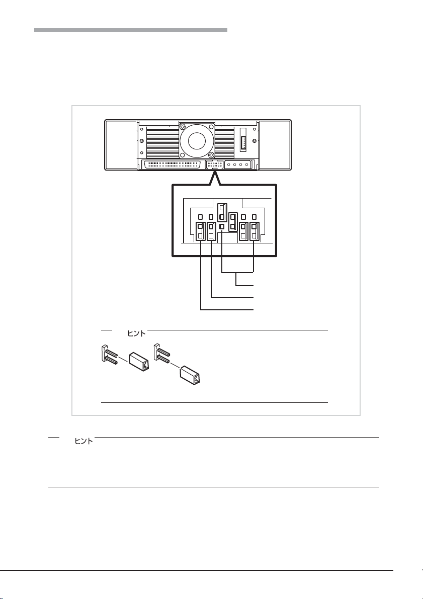
製品背面
内蔵
18
AIT
3
について
4
1 電源コネクタ
本体の内蔵
(→26ページ)。
2 ジャンパピン
内蔵
AIT
3
SCSI
本体の内蔵
(→26ページ)。
12
4 ファン
電源ケーブルを接続する
DC
の設定をするピン(→21ページ)。
コネクタ
ケーブルを接続する
SCSI
Page 20
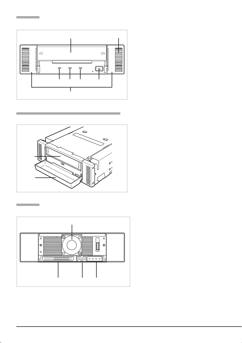
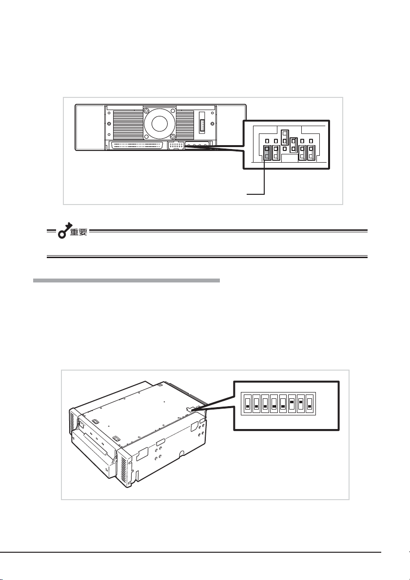
製品底面
セットアップ
12345678
1
スイッチ
ON
DIP
内蔵
の設定をするスイッチ
AIT
(→23ページ)。
1
本製品を
Express5800
シリーズ製品などの「本体装置」に取り付けるまでの手順を説明します。
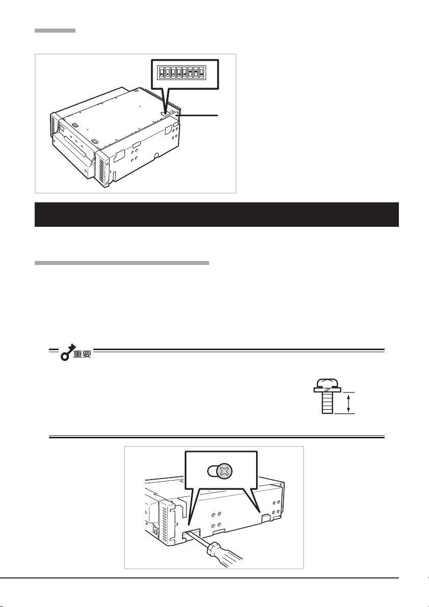
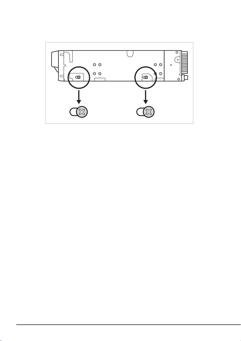
ブラケットの取り外し、取り付け方法
本製品を
ブラケットの取り外し
プラスドライバを使ってネジを取り外すと、ブラケットが外れます。
インチデバイスで使用するときは、左右のブラケットを取り外します。
3.5
● 取り外したブラケットとネジは、大切に保管しておいてください。
● このネジは、ブラケットを取り付けるときのみに使用します。
このネジはミリネジ(長さ
4.0 mm
となります。
)です。このネジより長いものを使用すると故障の原因
5.0 mm
、ワッシャより下の長さ
4.0 mm
ミリネジ
内蔵
AIT
について
19
Page 21
ブラケットの取り付け
本製品のネジ穴とブラケットの長穴の後部を合わせ、プラスドライバを使ってネジを取り
付けます。
20
内蔵
AIT
について
Page 22
内蔵
本製品の背面にあるジャンパピンでは次の設定を変更することができます。
の設定 〜ジャンパピンを使った設定〜
AIT
●
SCSI ID
● パリティ機能(工場出荷時の設定は「有効」)
(工場出荷時の設定は「
ID4
」)
(右からピン0〜3)
SCSI ID
未使用(NC)
パリティ(
PD
)
✎
「ジャンパプラグなし」にする場合
は、片方のピンにジャンパプラグを
取り付けておくか、ジャンパプラグ
を取り外します。取り外したジャン
パプラグは、大切に保管しておいて
ください。
✎
ここでの「ジャンパプラグあり」とは、2つのピンにジャンパプラグを取り付けた状態を
さします。また、「ジャンパプラグなし」はジャンパプラグをピンに取り付けていない
か、2つのピンのうち、どちらか一方のピンにのみ取り付けられている状態をさします。
内蔵
AIT
について
21
Page 23
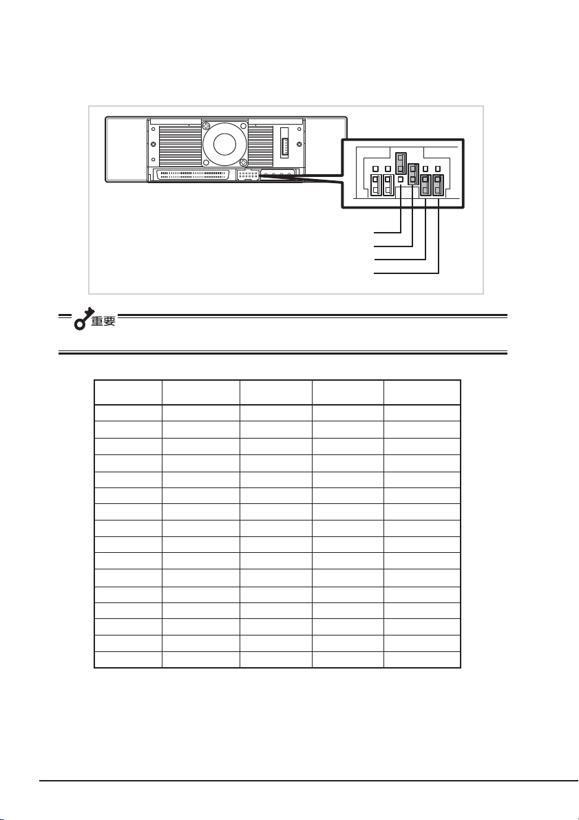
SCSI ID
の設定
本製品が使用する
ン
本のピンを使います。
3」の4
SCSI ID
を設定します。設定は背面にあるジャンパピンの「ピン0」〜「ピ
ピン3(工場出荷時:ジャンパプラグなし)
ピン2(工場出荷時: ジャンパプラグあり)
ピン1(工場出荷時: ジャンパプラグなし)
ピン0(工場出荷時: ジャンパプラグなし)
他の
機器と
SCSI
DIISCSンピ3 ンピ2 ンピ1 ンピ0
0 × × × ×
1 × × × ○
2 × × ○ ×
3 × × ○ ○
1
*4
5 × ○ × ○
6 × ○ ○ ×
2
*7
8 ○ × × ×
9 ○ × × ○
01 ○ × ○ ×
11 ○ × ○ ○
21 ○ ○ × ×
31 ○ ○ × ○
41 ○ ○ ○ ×
51 ○ ○ ○ ○
◯ ジャンパプラグあり
× ジャンパプラグなし
1
*
出荷時の設定。
2
*
SCSI IDをID7
SCSI ID
が重複していないことを確認してください。
×○××
×○○○
に設定しないでください。
22
内蔵
AIT
について
Page 24
パリティ機能の設定
パリティ機能の設定を設定します。設定は背面にあるジャンパピンの一番左側のピンを使
います。
ジャンパプラグなしにすると、パリティ機能は「有効」になります(工場出荷時の設定)。
ジャンパプラグありにするとパリティ機能は「無効」になります。
(工場出荷時: ジャンパプラグなし)
PD
信頼性を向上させるために、「有効(ジャンパプラグなし)」のままで使用してください。
内蔵
の設定 〜
AIT
本製品の底面にある
●
Terminator Power
●
DC Control (1)
●
DC Control (2)
スイッチを使った設定〜
DIP
スイッチでは次の設定を変更することができます。
DIP
(ターミネータ電源供給)(工場出荷時の設定は「
(データ圧縮設定)(工場出荷時の設定は「ON」)
(データ圧縮設定)(工場出荷時の設定は「
12345678
スイッチ1〜
スイッチ
スイッチ
スイッチ
スイッチ
OFF
未使用
4:
5: Terminator Power
未使用
6:
7: DC Control (1)
8: DC Control (2)
内蔵
」)
AIT
OFF
ON
について
」)
23
Page 25
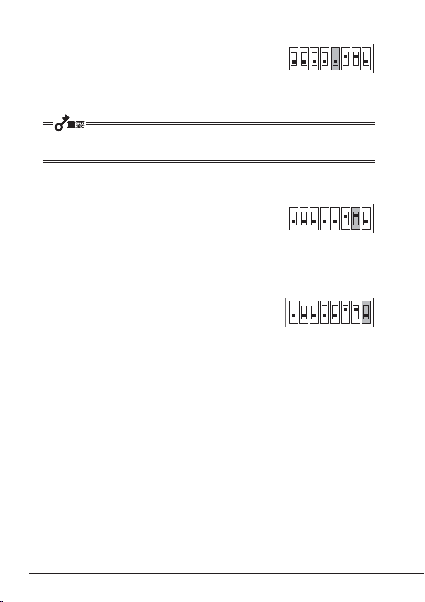
ターミネータ電源供給の設定 〜
ターミネータ電源を
設定します。
設定はスイッチ
給する設定に、「
になります。
を使います。「ON」でターミネータ電源を供
5
OFF
バスに供給するか供給しないかを
SCSI
(工場出荷時の設定)」で供給しない設定
Terminator Power
〜
ON
12345678
本製品を
使用する場合には、出荷時設定(
データ圧縮の設定 〜
本製品が持つデータ圧縮機能を有効にするか無効にするかを
設定します。
設定はスイッチ
データ圧縮機能を有効にする設定に、「
能を無効にする設定になります。
データ圧縮の設定 〜
バックアップソフトからデータ圧縮の制御を有効にするか無
効にするかを設定します。
設定はスイッチ
らのデータ圧縮制御を無効にする設定に、「
の設定)」でバックアップソフトからのデータ圧縮制御を有効
にする設定になります。
N8541-28、N8141-28A
DC Control (1)
を使います。「ON(工場出荷時の設定)」で
7
DC Control (2)
を使います。「ON」でバックアップソフトか
8
デバイス増設ユニットに搭載して、電源連動機能を
)のままにしてください。
OFF
〜
」でデータ圧縮機
OFF
〜
(工場出荷時
OFF
ON
12345678
ON
12345678
24
内蔵
AIT
について
Page 26
本体装置への取り付け
注意
電源がONのまま取り付け・取り外しをしない
本製品の取り付け・取り外しの際や、ケーブルの接続の際は必ず主電源
に接続している
コードをコンセントから抜いてください。ACコード
AC
がコンセントに接続されたまま取り付け・取り外しや接続をすると感電
をするおそれがあります。
本体装置機器等への設置方法例を以下に示します。
✎
本体装置によってはレールを使用するものもあります。設置方法については、本体装置
の取扱説明書も参照してください。
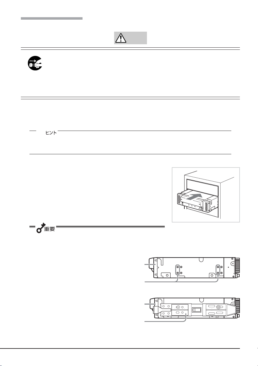
右の図の位置に
1.
● 本製品にレールを取り付ける場合は、
用してください(
対側も同様に、片側2箇所、計
箇所をネジ止めしてくださ
4
い。)
レールが、フロントカバー部の
モールド部までくる場合があり
ますが、問題ありません。
(
Fig. 3
(レールの形状は本体装置によ
り異なります。)
N8151-54内蔵AIT
Fig. 2
)
)。(反
を取り付けます。
に示すフロントカバー側のネジ穴を使
Fig. 1
フロントカバー
ネジ穴
フロントカバー
レール
Fig. 1
Fig. 2
内蔵
AIT
について
25
Page 27
フロントカバー
レール
Fig. 3
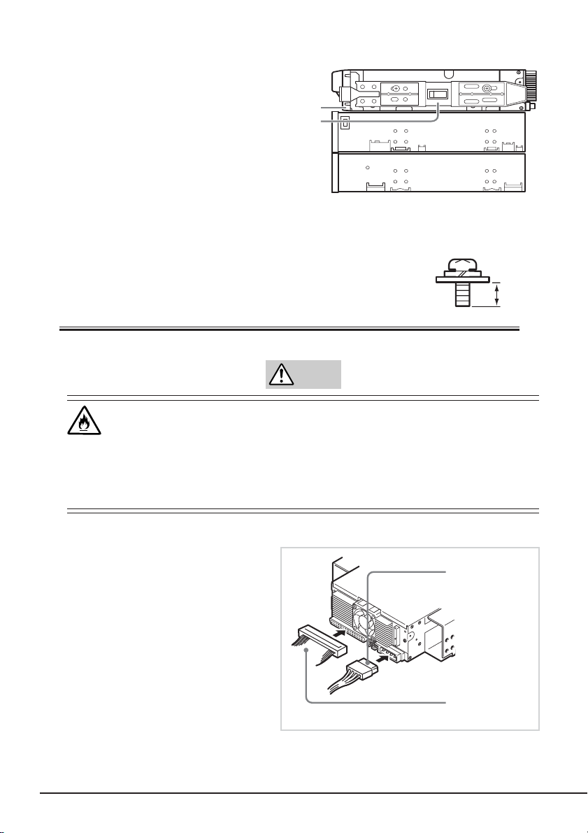
●
● 必ず本製品に添付されているネジを使って固定してください。本製品
インチデバイスタイプ、
5.25
ジは同じです。
に添付のネジは、ミリネジ(長さ
3.5 mm
原因となります。
)です。添付のネジより長いものを使用すると製品の故障の
3.5
インチデバイスタイプのどちらの場合も使用するネ
5.0 mm
、ワッシャより下の長さ
注意
破損したケーブルを使用しない
ケーブルを接続する前にコネクタが破損していたり、コネクタピンが曲
がっていたり、汚れたりしていないことを確認してください。破損や曲
がっているコネクタおよび汚れたコネクタを使用するとショートにより
火災を引き起こすおそれがあります。
右の図のようにケーブルを接続して
2.
ください。
3.5 mm
ミリネジ
電源ケーブル
DC
(システム内で使
用可能な空きコネ
クタ)
26
内蔵
AIT
について
インター
SCSI
フェースケーブル
Page 28

●本製品を
SCSI
ントローラとの接続以外では使用しないでください。
ただし、本体装置によっては、本製品添付の
ります。その場合は、本体装置に添付されている
い。
● 設置の際には、
● 本装置の出荷時の
ように設定してください。
● 本装置には、ターミネータ機能はありません。本装置が
合は、
本体装置にカバーを取り付けて、ACコードをコンセントに接続する。
3.
本体装置の電源をONにする。
4.
N8103-75 SCSI
ケーブルを使用してください。添付の
SCSI ID
SCSI ID
ケーブルの末端にターミネータを取り付けてください。
SCSI
コントローラを使用して接続する場合は、本製品添付の
ケーブルは、
SCSI
ケーブルを使用できない装置があ
SCSI
ケーブルを使用してくださ
SCSI
等の各設定の確認をお願いします。
は4に設定されております。他の
SCSI ID
接続の最遠端になる場
SCSI
N8103-75 SCSI
と重複しない
コ
5. SCSI
バスの設定が本体装置側でできる場合は、本製品について以下のように設定し
てください。
● 転送レート
●
データバス幅
●
DISCONNECT/RECONNECT機能:
本製品の最大転送レートは、
体装置は
160Mbyte
ただし、
なりますので、
また、本製品を
160Mbyte
秒未満の最大値に設定してください。
詳しくは、本体装置に添付の説明書を参照してください。
160Mbyte
/秒未満の最大値に設定してください。
N8103-75 SCSI
160Mbyte
N8141-28A
/秒に設定可能な場合でも
160Mbyte
/秒に設定し、
ボードを使用した場合は、
/秒に設定してください。
デバイス増設ユニットに接続する場合は、本体装置が
:160 Mbyte
ビット(
:
16
有効
/秒です。
160Mbyte
160Mbyte
/秒(最大、同期)
Ultra Wide SCSI、LVD/SE
160Mbyte
/秒に設定できない本体装置は
160Mbyte
/秒に設定せずに、
/秒に設定できる本
/秒に設定可能に
160Mbyte
)
/
内蔵
AIT
について
27
Page 29
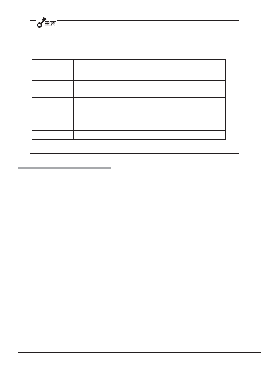
同一バス上に接続されているデバイス数および
転送レートを設定してください。
下記の値は目安です。他で指定がある場合は、そちらに設定してください。
ケーブル長により、下記の通り最大
SCSI
SCSI
Ultra 160 SCSI 160 16 4 12 16
Ultra 2 Wide SCSI
Ultra Wide SCSI 40 16 3 - 4
Ultra Wide SCSI 40 16 1.5 - 8
Ultra Wide SCSI 40 16 - 3 16
Fast Wide SCSI 20 16 3 3 16
Wide SCSI 10 16 6 3 8
ホストおよび同一バス上の全デバイスが
*SCSI
最大転送レート データバス幅 最大ケーブル長
(Mbyte/s) (bit)
80 16 - 12 16
Single-ended
対応の場合
LVD
(m)
LVD*
最大デバイス数
(
ホスト
SCSI
デバイス数)
+
バックアップソフト使用のご注意
NECのWeb
「テクニカル情報(テクニカルガイド)」−「
情報ページである8番街(
http://www.express.nec.co.jp
Express5800/100
シリーズテクニカルガイド」に
ありますバックアップ装置の<バックアップ装置対応ソフトウェア>を確認してください。
問い合わせ先:
webmaster@ace.comp.nec.co.jp
)の「サポート情報」−
28
内蔵
AIT
について
Page 30
テープデバイスドライバのインストール
Windows 2000のWindows
アップ(システムツール)、および
のみインストールしてください。
本体装置にテープデバイスドライバをインストールします。ドライバのインストールに
は、添付のフロッピィディスクを使用します。あらかじめ用意しておいてください。
●
Windows 2000
「スタート」ボタンをクリックし、「設定」をポイントし、「コントロールパネル」をク
1.
リックして、「システム」をダブルクリックする。
「システムのプロパティ」ダイアログボックスが表示されます。
「ハードウェア」タブをクリックし、「デバイスマネージャ」ボタンをクリックする。
2.
「デバイスマネージャ」ダイアログボックスが表示されます。
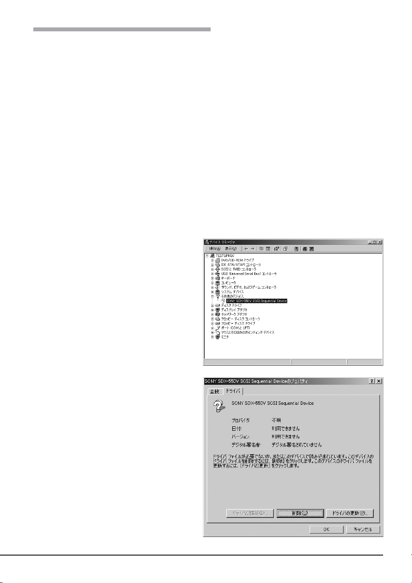
「その他のデバイス」に「
3.
でドライブをご使用のお客様
バックアップ(システムツール)、
Windows Server 2003
のバックアップを使用する方
SONY
Windows XP
のバック
SDX-550V SCSI Sequential
Device
確認し、「
SCSI Sequential Device
ルクリックする。
「
SONY SDX-550V SCSI Se-
quential Device
イアログボックスが表示されます。
」と表示されていることを
SONY SDX-550V
」をダブ
のプロパティ」ダ
「ドライバ」タブをクリックし、「ド
4.
ライバの更新」ボタンをクリックす
る。
「デバイスドライバのアップグレー
ドウィザード」が表示されます。
内蔵
AIT
について
29
Page 31

「次へ」ボタンをクリックする。
5.
「ハードウェアデバイスドライバの
インストール」画面が表示されま
す。
「デバイスに最適なドライバを検索
6.
する(推奨)」を選択し、「次へ」ボタ
ンをクリックする。
「ドライバファイルの特定」画面が表
示されます。
添付のフロッピーディスクを挿入し
ます。
「フロッピーディスクドライブ」にの
7.
みチェックを入れ、「次へ」ボタンを
クリックする。
「ドライバファイルの検索」画面が表
示されます。
ドライバファイルの検索が始まりま
す。
8.「a:¥win2000¥32¥s32ait.inf
選ばれていることを確認し、[次へ]
ボタンをクリックする。
「デバイスドライバのアップグレー
ドウィザードの完了」画面が表示さ
れます。
30
内蔵
AIT
について
」が
Page 32

[完了]ボタンをクリックする。
9.
「デバイスマネージャ」ダイアログ
10.
ボックスで、
ニットが表示されていることを確認
する。
テープドライブユ
AIT
内蔵
AIT
について
31
Page 33

●
Windows XP
「スタート」ボタンをクリックし、「コントロールパネル」をクリックして、「システム」
1.
をダブルクリックする。
「システムのプロパティ」ダイアログボックスが表示されます。
「ハードウェア」タブをクリックし、「デバイスマネージャ」ボタンをクリックする。
2.
「デバイスマネージャ」ダイアログボックスが表示されます。
「その他のデバイス」に「
3.
でドライブをご使用のお客様
SONY
SDX-550V SCSI Sequential
Device
認し、「
Sequential Device
リックする。
「
quential Device
イアログボックスが表示されます。
「ドライバ」タブをクリックし、「ドラ
4.
イバの更新」ボタンをクリックする。
」と表示されていることを確
SONY SDX-550V SCSI
」をダブルク
SONY SDX-550V SCSI Se-
のプロパティ」ダ
「ハードウェアの更新ウィザード」が
表示されます。
32
内蔵
AIT
について
Page 34

「ソフトウェアを自動的にインス
5.
トールする(推奨)」を選択し、フ
ロッピーを挿入して、「次へ」ボタン
をクリックする。
「下の一覧からハードウェアに最適
なソフトウェアを選んでくださ
い。」画面が表示されます。
一覧から「
6.
を選択し、「次へ」ボタンをクリック
する。
「ハードウェアの更新ウィザードの
完了」画面が表示されます。
「完了」ボタンをクリックする。
7.
a:¥xp¥32¥s32ait.inf
」
内蔵
AIT
について
33
Page 35

「デバイスマネージャ」ダイアログ
8.
ボックスで、
ニットが表示されていることを確認
する。
テープドライブユ
AIT
✎
インストールしたテープデバイスドライバは、システムの再起動後に有効になります。
34
内蔵
AIT
について
Page 36

●
Windows Server 2003
「スタート」ボタンをクリックし、「コントロールパネル」をポイントして、「システム」
1.
をクリックする。
「システムのプロパティ」ダイアログボックスが表示されます。
「ハードウェア」タブをクリックし、「デバイスマネージャ」ボタンをクリックする。
2.
「デバイスマネージャ」ダイアログボックスが表示されます。
「その他のデバイス」に「
3.
でドライブをご使用のお客様
SONY
SDX-550V SCSI Sequential
Device
認し、
「
quential Device
クする。
「
quential Device
イアログボックスが表示されます。
「ドライバ」タブをクリックし、「ドラ
4.
イバの更新」ボタンをクリックする。
」と表示されていることを確
SONY SDX-550V SCSI Se-
」をダブルクリッ
SONY SDX-550V SCSI Se-
のプロパティ」ダ
「新しいハードウェアの検出ウィザー
ド」が表示されます。
内蔵
AIT
について
35
Page 37

「ソフトウェアを自動的にインス
5.
トールする(推奨)」を選択し、フ
ロッピーを挿入して、「次へ」ボタン
をクリックする。
「下の一覧からハードウェアに最適
なソフトウェアを選んで下さい。」
画面が表示されます。
一覧から
6.
「
a:¥w2k3¥32¥s32ait.inf
し、「次へ」ボタンをクリックする。
「ハードウェアの更新ウィザードの
完了」画面が表示されます。
「完了」ボタンをクリックする。
7.
」を選択
36
内蔵
AIT
について
Page 38

「デバイスマネージャ」ダイアログ
8.
ボックスで、
ニットが表示されていることを確認
する。
以上でテープデバイスドライバのインストールが完了しました。
テープドライブユ
AIT
内蔵
AIT
について
37
Page 39

ASR
機能を使用する場合
WindowsのASR(Automated System Recovery*
ピーディスクからファイルを読み込んでデバイスドライバをインストールする必要があり
ます。空のフロッピーディスクをご用意いただき、添付の
「
DeviceDriver
さい。
フロッピーディスクを作成する際は、
ファイルパスが重要になります。
「
DeviceDriver
の画面イメージになるようにコピーし
てください。(「
ダ自身は含みません)
」フォルダの配下にあるファイルをフロッピーディスクにコピーしてくだ
」フォルダの下を下記
DeviceDriver
」フォル
)機能を使用する場合は、フロッ
CD-ROM
内の
*ASR(Automated System Recovery
Windows XP、Windows Server 2003
ドウェア構成、アプリケーションを保存し、災害から回復する過程において1ステップで復元するこ
とが可能です。詳しい使用方法等については、OS、バックアップソフトのマニュアルを参照くださ
い。
Windows 2000はASR
38
内蔵
AIT
について
機能をサポートしておりません。
)
でサポートされている機能で、OSやシステム状態、ハー
Page 40

取り扱い
本製品の取り扱い方法を説明します。
データカートリッジのセット
AIT
● 本製品にセットするデータカートリッジには、当社製の「
使用してください。当社製以外のデータカートリッジを使用するとリード/ライトエ
ラーを起こすことがあります。
● データカートリッジをセットしている間は、本体装置の電源を
さい。誤動作やデータ破壊の原因となります。
本体装置の電源をONにした後、本
1.
製品の
REPLACE TAPE LED
と
TAPE MOTION LED、CLEANING REQUEST LED
ことを確認する。
防塵カバーを指で開く。
2.
が消灯した
データカートリッジ」を
AIT
にしないでくだ
OFF
内蔵
AIT
について
39
Page 41

3. AIT
データカートリッジを右図の向
きにして本製品のデータカート
リッジ挿入口に挿入する。
ある程度挿入するとデータカート
リッジは自動的に本製品内部に
セットされ、
が点灯します。
LED
防塵カバーを閉める。
4.
● 防塵カバーの取り付け
TAPE MOTION
防塵カバーは破損防止のため、力が
加わると外れる構造になっていま
す。防塵カバーが外れた場合は、
に示す矢印の方向に防塵カ
Fig. 1
バーの両端を、片方ずつ、やや斜め
上からまっすぐに押し、カチッと音
がするまで押し込むことで取り付け
ることができます。
Fig. 1
防塵カバー
40
内蔵
AIT
について
Page 42

データカートリッジの取り出し
AIT
1. TAPE MOTION LED
いないことを確認する。
が点滅して
2. EJECT
巻き戻しが始まります(巻き戻しに
数分かかる場合があります)。
巻き戻しが終わるとデータカート
リッジは自動的に製品内から排出
されます。
防塵カバーを指で開く。
3.
ボタンを押すと、テープの
バックアップソフト、OSのロックにより、
出されない場合があります。バックアップソフトによるカートリッジ排出、またはしば
らく待ってから
ボタンを一定時間(5秒〜10秒)押し続け、強制排出を行ってください。
EJECT
EJECT
ボタンを押してください。それでも排出されない場合は、
ボタンを押してもカートリッジが排
EJECT
内蔵
AIT
について
41
Page 43

データカートリッジ挿入口から
4.
データカートリッジを取り出し、
防塵カバーを閉める。
●
TAPE MOTION LED
が点灯、または点滅している間は、本体装置の電源を
しないでください。誤動作やデータの破壊の原因となります。
● 本製品にデータカートリッジを挿入したまま移動しないでください。本製品の故障の
原因となります。
● バックアップ完了後は、カートリッジを取り出してください。
表示
LED
本製品前面にある3つの
消灯
点灯
点滅(
点滅(
すべての
点滅(
点滅(
点滅(
LED
Slowly
)
Fast
LED
)
Fast
):
Fast
):
Slowly
)
が
TAPE MOTION
データカートリッジがセット
されていない。
データカートリッジがセット
されている。
セットされているデータカー
トリッジが正常に動いている
(
Write/Read
セットされているデータカー
トリッジが正常に動いている
(
Write/Read
本製品が故障している。
秒点灯/
0.3
秒点灯/
0.9
で、本製品や
LED
)。
以外)。
秒消灯
0.3
秒消灯
0.3
データカートリッジの状態を知らせます。
AIT
CLEANING REQUEST
本製品のクリーニングの必要
はない。
本製品のクリーニングが必要
である。
ヘッドクリーニング中、ク
リーニングカートリッジの
テープが終了した。
−
REPLACE TAPE
データカートリッジにエラー
は起きていない。
データカートリッジにエラー
が起きている。
−
−
OFF
に
データのリード/ライト
データカートリッジからのデータの読み込み(
AIT
については、バックアップソフトに添付の説明書を参照してください。
42
内蔵
AIT
について
)、または書き込み(
Read
Write
)の方法
Page 44

クリーニング
本製品を良い状態に保つために、定期的にクリーニングをしてください。
リード/ライトヘッドのクリーニング
CLEANING REQUEST LED
ドを清掃してください。
添付のクリーニングカートリッジ(
セット」で説明している手順で本製品にセットします。
クリーニングカートリッジをセットすると自動的にヘッドのクリーニングが開始されま
す。
クリーニングが終了すると、自動的にクリーニングカートリッジが出てきます(開始から
約
秒後)。クリーニングカートリッジを取り出してください。
35
● 本製品のクリーニングには、当社製の「
)」を使用してください。当社製以外のクリーナーを使用すると故障の原因と
3237J
なることがあります。
● クリーニングカートリッジのテープ面を手で
触ったり、テープを巻き戻して使用したりし
ないでください。
● クリーニングカートリッジは約70回使用する
ことができます。本製品では、使い切ったク
リーニングカートリッジを挿入した場合や、
クリーニング中にテープが使い切られたため
に正常にクリーニングが終了しなかった場合
でも、クリーニングカートリッジは自動的に
排出されません。このような場合は、
ボタンを押して、クリーニングカー
EJECT
トリッジを取り出してください。新しいク
リーニングカートリッジを別途お買い求めく
ださい。
が点灯しているときは、本製品内部のリード/ライトヘッ
EF-3237J
)を「取り扱い」の「
クリーニングカートリッジ(型番
AIT
データカートリッジの
AIT
: EF-
✎
リード/ライトヘッドは、1週間に1回、使用する前にクリーニングカートリッジで清掃
することをお勧めします(使用している環境(チリやホコリの発生状況)や使用回数によっ
て異なりますが、一般的な事務室などで毎日使用する場合、1週間に1回の清掃を目安と
してください)。
内蔵
AIT
について
43
Page 45

本体のクリーニング
本製品の外観が汚れたときは、やわらかい布に水または洗剤を含ませて軽く拭いてくださ
い。
ベンジン、シンナーなど(揮発性のもの)の薬品で拭くと、変形や変色の原因となること
があります。また、殺虫剤をかけた場合も変形や変色の原因となることがあります。薬
品が付着したら、早めに水を含ませた柔らかい布で拭き取ってください。
44
内蔵
AIT
について
Page 46

AIT
データカートリッジ(
品)について
データカートリッジの取り扱い方法について説明します。
AIT
データカートリッジの各部の名称
ラベル貼り付け位置
EF
型番
ラベル貼り付け位置
ライトプロテクト
プラグ
取り付け/取り外し時
の取っ手(反対側にも
あります)
データカートリッジについて
AIT
45
Page 47

使用・保管・運搬条件
■ 使用条件
温度
湿度
放置時間 使用および保管環境条件以外の環境に
■ 保管条件
温度
湿度
保管状態
■ 運搬条件
温度
湿度
温度勾配 最大
10〜45
20〜80
されていた場合には、使用および保管環境条件以外の環境にさらさ
れていた時間より長く(最大
てください。温度勾配は最大10℃/時間とします。
5〜32
20〜60
AIT
てください。置き方は水平、垂直どちらでもかまいません。
–40〜45
5〜80
℃
%(ただし、湿球の最高温度は26℃とします。)
℃
%(ただし、湿球の最高温度は26℃とします。)
データカートリッジは、保護ケースに入れて、フタをして保管し
℃
%(ただし、湿球の最高温度は26℃とします。)
℃/時間
10
データカートリッジがさら
AIT
時間)使用環境になじませてから使用し
8
運搬状態
ラベル
どの
ように
ラベル貼り付け位置
46 AIT
データカートリッジにどのデータをバックアップしているかなどがすぐにわかる
AIT
データカートリッジにラベルを貼り付けておくことをお勧めします。
AIT
データカートリッジについて
データカートリッジを保護ケースに収納してください。輸送の場
AIT
合には、
ださい。
データカートリッジに力が加わらないように包装してく
AIT
Page 48

ラベルへの記入上の注意事項
●
データカートリッジの内容を表示するために用いるラベルは簡単に取り換える
AIT
ことができ、取り外した後に粘着物が残らないようなものを使用してください。
● 内容の表示を変更するときは、消しゴムで消さず、必ずラベルを貼り替えてくださ
い(
INDEX
● ラベルを貼るときは、前項で指定された位置に確実に貼り、さらに取り換える場合
は古いラベルを取り除いてから新しいラベルを貼ってください。
● 指定の
てください。
● 添付の
リッジの寿命をチェックする目安となります。
ラベルは
INDEX
INDEX
ラベル以外のものを使用する場合は、大きさが合ったものを使用し
ラベルには、使用開始年月日を記入してください。
データカートリッジに添付されています)。
AIT
データカート
AIT
ライトプロテクト
ライトプロテクトプラグを右図のように
設定すると、テープの内容が保護されま
す。
書き込んだデータを消去したくないとき
は、このプラグを「
不可)に設定してください。また、プラ
グを「
るとテープに書き込み可能となります。
」側(書き込み可能)に設定す
REC
SAFE
」側(書き込み
EF-2429
EF-2423
EF-2423S
EF-2431
書き込み不可書き込み可能
ライトプロテクト
プラグ
EF-2420L
EF-2420
書き込み不可書き込み可能
ライトプロテクト
プラグ
データカートリッジについて
AIT
47
Page 49

取り扱い上の注意事項
使用上のご注意
使用する前
● 使用する
り、曲がっているときは、使用しないでください。
● 製品の使用温湿度条件以外で保管されていた
合は、使用温湿度条件以外にあった時間より長く(最大8時間)、使用環境に持ち込
んでから使用してください。保管場所と使用場所の温度差が大きい場合は、一度に
持ち込むのではなく、温度変化が
カートリッジを使用場所の温度になじませてください。
製品への装着
「
データカートリッジのセット」での説明に従って
AIT
てください。
チリやホコリの少ない場所で保管してください。
使用した後
使用済みの
所で保管してください。置き方は水平、垂直どちらでもかまいません。
AIT
データカートリッジが、外的損害を受けていたり、または変形した
AIT
データカートリッジを使用する場
AIT
時間に10℃以下になるようにして、
1
データカートリッジをセットし
AIT
データカートリッジを取り出した後の保護ケースは、しっかりと閉じ、
AIT
データカートリッジは、必ず保護ケースに入れてチリやホコリの少ない場
AIT
データ
一般的注意事項
● テープに手を触れないでくださ
い。また、テープカバーを開閉
しないでください。
● 磁気を発生するものを近づけな
いでください。
● 直射日光や暖房器具の近くには
置かないでください。
● 強い衝撃を与えないでください。
● 飲食や喫煙をしながらの取り扱いは避けてください。また、シンナーやアルコール
などを付着させないように注意してください。
● 製品への挿入は、ていねいに行ってください。
48 AIT
データカートリッジについて
テープ面
テープカバー
Page 50

使用禁止基準
以下の項目に該当する場合は、新しい
す。
● 落下させるなど強い衝撃を与え、
強い衝撃を受けた場合、カートリッジが変形したり、欠けたりする場合がありま
す。また、テープカバーが正常に開閉しなくなり、カートリッジが排出されないと
いった障害の原因となります。
● 清涼飲料、コーヒー、紅茶など液体、溶剤や金属粉、たばこの灰などで記録面が汚
れている場合。
この状態で
汚したりすることになり、製品の故障の原因となります。また、ヘッドの汚れやキ
ズに気づかず、新しい
トリッジを汚したり、傷つけたりして被害を広げることになります。
データカートリッジを製品に挿入するとヘッドや製品を損傷したり、
AIT
データカートリッジを製品に挿入すると、
AIT
データカートリッジに取り替える必要がありま
AIT
データカートリッジが損傷を受けた場合。
AIT
データカー
AIT
寿命
テープの寿命は、温度・湿度、ヘッドクリーニング回数などによって左右されます。
AIT
毎日
回使用した場合は、使用開始より1年後、毎回使用していない場合でも、使用開始よ
1
り
年後に交換をお願いします。また、エラーが頻繁に発生する場合は、その前に交換を
2
お願いします。
データカートリッジの寿命管理として下記の手順を実施していただくことをお勧めし
AIT
ます。
● 新しい
トリッジのラベルに記入しておきます。
●
AIT
ジの使用年数と使用回数を見積もります。
● 定期的に
いたり、書き込み、読み取りエラーが発生するなど信頼性が低い
リッジを廃棄します。
また、テープ磁性層は、化学物質で構成されており、時間経過と共に劣化します。
この劣化によるテープ寿命は、テープ保管の環境(温度・湿度)により大きく異なります
が、カートリッジを使用していない場合でもテープを購入してから約
てください。
データカートリッジに管理番号を割り当て、その番号を
AIT
データカートリッジ管理台帳を作り、使用日を記録し、
データカートリッジの管理台帳と標識ラベルを調べ、長く使用されて
AIT
データカートリッジについて
AIT
データカー
AIT
データカートリッ
AIT
データカート
AIT
年を目安に交換し
3
49
Page 51

重要なデータの保存について
重要なデータまたはプログラムなどを保存する場合には、万一の場合に備えて、正副2巻
に保存することをお勧めします。
また、保存する際にはバックアップソフトのベリファイ機能を利用し、保存したデータの
確認も行うことをお勧めします。ベリファイ機能の利用方法については、各バックアップ
ソフトの取扱説明書を参照してください。
こうしておけば、一方のテープがチリやホコリによるリードエラーを起こしても、もう一
方のテープから復旧でき、大切なデータやプログラムの消失を防げます。
データの3世代管理について
ディスク上のデータを保存する場合は、保存したデータの3世代管理をお勧めします。
世代管理は、テープ3巻(A、B、C)を使用して、ディスク上のデータを1日目はテープ
3
に保存し、2日目はテープBに、3日目はテープCに保存していくものです。
これにより、例えば一巻のテープ
してデータを復旧でき、また、テープ
タを使用して大切なデータを復旧することができます。
がリードエラーを起こした場合には、データBを使用
C
がリードエラーを起こした場合でもテープAのデー
B
データカートリッジの保管について
A
決められた保管条件を守り、保管場所を常に清潔に保ってください。
書き込みを禁止にしておくことをお勧めします。
長期間にわたって保管する場合は、常にバックアップデータが復旧可能であることを確認
するため、定期的にデータの読み出しを行ってください。
万一の場合を想定してシステムから遠く離れた場所に保管しておくことをお勧めします。
正副
巻のデータカートリッジがある場合には、正、副それぞれを異なる場所に保管して
2
おくとさらに効果的です。
バックアップと惨事復旧手順の制定
バックアップ方法を定めるときは、常に惨事復旧を想定したスケジュールを組んでくださ
い。バックアップ・リストアの正しい手順を制定することが、バックアップの運用の第一
歩です。惨事復旧の手順を確立し、正しく運用されることを定期的に確認してください。
50 AIT
データカートリッジについて
Page 52

仕 様
本製品の仕様について記載します。
■ 性 能
記憶容量
ビットエラーレート
データ転送速度(
バーストデータ転送速度(
イニシャライズ時間
ロード時間 平均25秒
アンロード時間 平均
巻き戻し時間 平均
■ 環境条件
使用時 温度
TAPE
)
SCSI)160 Mbyte
17
−
(圧縮時:
(圧縮時:
(圧縮時:
(圧縮時:
(圧縮時:
(圧縮時:
以下
160 Gbyte) EF-2431
100 Gbyte) EF-2423
72 Gbyte) EF-2423S
80 Gbyte) EF-2429
70 Gbyte) EF-2420L
50 Gbyte) EF-2420
• 80 Gbyte
• 50 Gbyte
• 36 Gbyte
• 40 Gbyte
• 35 Gbyte
• 25 Gbyte
圧縮時の値は圧縮効率が2倍である場合の値です。
圧縮効率はデータパターンにより変化します。
10
•AIT-1 Turbo、AIT-2、AIT-2 Turbo
12 Mbyte
• AIT-1:8 Mbyte
データ転送速度は接続しているサーバのシステム
環境により変化します。
接続環境によっては、
きない場合もあります。
秒未満
5
平均
平均14秒
EF-2423S
平均20秒
EF-2423S
平均
平均80秒
リトライ処理が発生した場合は上記秒数を超える
場合があります。
湿度
最大湿球温度
/秒(非圧縮時)
/秒(非圧縮時)
/秒(最大、同期)
160 Mbyte
EF-2431
80秒 EF-2429
使用時
使用時
EF-2420L、EF-2420、EF-2423
使用時
25秒 EF-2431、EF-2429
使用時
EF-2420L、EF-2420、EF-2423
使用時
90秒 EF-2431、EF-2429
使用時
105秒 EF-2420L、EF-2423、EF-2423S
EF-2420
: 10℃〜35
: 20%〜80%
使用時
℃
(結露なきこと)
℃
: 26
使用時
使用時
使用時
使用時
使用時
使用時
:
/秒に設定で
、
、
使用時
非動作時 温度
湿度
: −40℃〜70
: 5%〜95%
(結露なきこと)
℃
仕 様
51
Page 53

■ 電源仕様
電圧
電流(
Typ.
電流(
Max.
■ 寸法・重量
%
5V±5
)
)
1.6 A 0.5 A
1.9 A 1.2 A
12 V±10
%
N8151-54 5.25
41.2 mm
149.0 mm
N8151-54 3.5
41.2 mm
101.6 mm
インチデバイスタイプ
インチデバイスタイプ
172.2 mm
172.2 mm
重量
重量
1.05 kg
0.78 kg
52
仕 様
Page 54

運用状況お客様記入シート
本製品を保守・管理する際に必要な情報を記録しておくメモ欄です。
項目 記入欄
本体装置モデル名
オペレーティングシステム(OS)
(名称、バージョン、サービス
パック/パッチの適用状況)
バックアップソフト
(名称、バージョン、サービス
パック/パッチの適用状況)
バス構成
SCSI
(
SCSI ID
ス)製品設置環境
製品設置環境
(温度、湿度、ホコリの状況な
ど)
カートリッジ種類
(メーカ名、EF型番)
/同一バス上のデバイ
クリーニングカートリッジ種類
(メーカ名、EF型番)
クリーニングカートリッジ使
用状況(クリーニング周期、使
用回数や使用開始月の管理方
法など)
カートリッジ使用状況
(使用回数や使用開始月の管理
方法など)
カートリッジの管理状況
運用状況お客様記入シート
53
Page 55

トラブルシューティング
本製品が思うように動作しない場合は、修理に出す前に以下のチェックリストの内容に
従って、本製品をチェックしてください。リストにある症状に当てはまる項目があると
きは、処置に従ってください。
チェックリスト
項番 症状
□ ドライブの電源が入らな
1
い。
□
が点灯しない。
LED
□ システム起動時にドライ
2
ブが正しく認識されな
い。
内蔵型
外付型
内蔵型
外付型
内蔵型
外付型
処置
□ ドライブにDCケーブルが正しく接続されている
ことを確認してください。
□ 集合型ドライブでは電源コネクタを2カ所持って
いるものがあります(専用のDCケーブルが必要な
ドライブがあります)。取扱説明書を確認して正
しく接続されていることを確認してください。
□DCケーブルの接触不良が無いか、挿抜して確認
してください。
□ ドライブにACコードが正しく接続されているこ
とを確認してください。
□ACコードが正しくコンセントに接続されている
ことを確認してください。
□ ドライブに
ることを確認してください。
□
□同一
ケーブルが正しく
SCSI
コネクタ、MBのコネクタなど)に接続されている
ことを確認してください。
SCSI
じではないか確認してください。
→同じ
SCSI ID
のIDを使われていない番号へ変更してくださ
い(
“7”
てないでください)。
ケーブルが正しく接続されてい
SCSI
SCSI I/F(SCSI
バス上の他のドライブと
のドライブがある場合、どちらか
はホスト側が使用しているため、割り当
ボードの
SCSI ID
が同
トラブルシューティングチェックリスト
54
Page 56

項番 症状
□ システム起動時にドライ
2
ブが正しく認識されな
い。
□OS起動後にドライブが
3
正しく認識されない。
(システム起動時は正し
く認識されていた。)
内蔵型
外付型
内蔵型
外付型
内蔵型
外付型
処置
□ 終端抵抗が正しく接続・設定されていることを確
認してください。
→ 終端抵抗は
いる必要があります。
・最遠端がケーブル(コネクタ)の場合、終端
コネクタが接続されていることを確認して
ください。
・ 最遠端が内蔵型ドライブの場合、ドライブ
の終端抵抗設定がONとなっていることを
確認してください。
・ 最遠端が外付型ドライブの場合、終端コネ
クタが接続されていることを確認してくだ
さい。
・ 最遠端が
BIOS
確認してください(それぞれの取扱説明書を
参照してください)。
・ 最遠端でないドライブの終端抵抗がONと
なっていないことを確認してください。
□
タイプの
PIN
生していないか確認してください(内蔵型
ドライブ側、内蔵/外付
付型
50pin[PIN
→ 折れた
□
SCSI BIOS
(取扱説明書に設定方法がかかれている場合は参
照してください。
のもあります)。
□ システム構成上、正しい位置に接続されているか
確認してください。
□ デバイスドライバが正しくインストールされてい
るか確認してください。
→ 自動的にインストールされる場合と、手動でイ
□ デバイスドライバが正しく起動されているか確認
してください。
PIN
るいはケーブルを交換してください。
ンストールする必要のある場合があります。ま
たデバイスドライバが製品に添付されている場
合があります。取扱説明書を参照してくださ
い。
バスの両最遠端に接続されて
SCSI
ボード(MB)の場合、
SCSI
などで正しく設定されていることを
コネクタの場合、
SCSI
PIN
SCSI
折れが発
50pin
のケーブル側、外
68pin
タイプ]のケーブル側など)。
を元に戻して使わずに、ドライブあ
の設定が正しいか確認してください
SCSI BIOS
が変更できないも
の
トラブルシューティングチェックリスト
55
Page 57

項番 症状
□ 正しくテープを認識しな
4
い。
□ 正しくバックアップがで
きない。
(バックアップソフトは
ドライブを正しく認識し
ている。)
□ 正しくバックアップがで
5
きない。
(バックアップソフトが
ドライブを正しく認識し
ていない。)
内蔵型
外付型
内蔵型
外付型
内蔵型
外付型
処置
□ クリーニングテープでヘッドのクリーニングを
行ってください。
□ データテープを新品と交換してください。
□ 正しいデータテープを使用しているか確認してく
ださい。
→・
・ 動作保証のされたテープ(EF型番テープな
・ 寿命に達したテープを使用していないか確
・ エラーの発生していたテープを使用してい
□
SCSI
問題がある可能性があります。
→ もう1度接続を確認してください。
□ 温度・湿度の異なる環境から持ち込んだドライブ
は、使用環境に十分馴染んでいない場合がありま
す。環境の馴染ませを行ってから使用してくださ
い。
□ 空調管理の行われていない環境でシステム起動直
後にバックアップを行うと、ドライブが環境に十
分馴染んでいない場合があります。環境に十分馴
染んでからバックアップするように運用の変更を
行ってください(夜間のシステム起動・バック
アップ開始などで発生しやすい)。
□ バックアップソフトが正しくインストールされて
いるか確認してください。
□
SCSI
いか確認してください。
□ ソフトウェア同士の競合が発生していないか確認
してください。
→ 同時に使用できないデバイスドライバが組み込
まれている場合に片方のドライバを外す必要の
ある場合があります。詳しくはソフトウェア側
の説明書を参照してください。
□
SCSI
問題がある可能性があります。
→ もう1度接続を確認してください。
ドライブに
DDS2
いないか、などのドライブとテープの組み
合わせは正しいか確認してください。
ど)を使用しているか確認してください。
認してください。
ないか確認してください。
ケーブル、コネクタ、終端抵抗等の接続に
バス上の他のデバイスとIDが重複していな
ケーブル、コネクタ、終端抵抗等の接続に
テープを使用して
DDS3
トラブルシューティングチェックリスト
56
Page 58

項番 症状
□ 正しくバックアップがで
6
きない。
(
が点滅している、
LED
にエラーを表示し
LCD
ている。)
□ テープが取り出せない。
7
(データテープの場合)
内蔵型
外付型
内蔵型
外付型
内蔵型
外付型
処置
□ 取扱説明書に
ある場合は、それを参照してください。
→・クリーニング要求の出ている場合は、ク
・エラー表示(
□ バックアップソフトで自動排出を設定したにも関
わらず排出されない場合は、正しくバックアップ
ができていないことが考えられます。
→項番4〜6を参照してください。
□ ドライブの
されない場合は、バックアップソフトによるソフ
トウェア的なロックのはたらいていることが考え
られます。
→・ソフトウェアを終了させてください。
・ システムを再起動してください。
・ 電源の
□ ドライブが何らかの不具合を検出して排出させな
いようにしていることが考えられます。
→・
・ システムを再起動してください。
・ 電源の
□テープがドライブ内部で絡まっていること(テー
プジャム)が考えられます。(
定時間以上押しても排出されない場合)
→・テープジャムを起こしたドライブは、内部
LED・LCD
リーニング実施後にバックアップを行い、
再発するようであればデータテープの交換
を行ってください。
は、ドライブに何らかの不具合を生じてい
ることが考えられるため、ドライブの交換
を行ってください。
EJECT
OFF/ON
キーを一定時間(5秒または10秒)以
EJECT
上押下し続けることで強制排出されるドラ
イブがありますので、これを行ってくださ
い。強制排出の手順に従い、手動で取り出
すことをお勧めします。
OFF/ON
のヘッド・ドラム・各ガイドピンなどを傷
めていることが考えられるため、ドライブ
交換を行ってください。
の表示に関する説明が
など)の出ている場合
ERRxx
キーを押下してもテープが排出
を行ってください。
を行ってください。
ボタンを一
EJECT
トラブルシューティングチェックリスト
57
Page 59

項番 症状
□ テープが取り出せない。
8
(クリーニングテープの
場合)
内蔵型
外付型
内蔵型
外付型
処置
□ 使い切ったクリーニングテープを挿入した場合、
あるいはクリーニング中に使い切ったため正常に
クリーニングが終了しなかった場合に、それを知
らせるためにクリーニングテープが排出されない
ドライブがあります。
→
□テープがドライブ内部で絡まっていること(テー
プジャム)が考えられます。(
定時間以上押しても排出されない場合)
→・テープジャムを起こしたドライブは、内部
キーを押下してクリーニングテープを
EJECT
取り出し、新しいクリーニングテープでクリー
ニングを再度行ってください。
ボタンを一
EJECT
のヘッド・ドラム・各ガイドピンなどを傷
めていることが考えられるため、ドライブ
交換を行ってください。
□ マガジンが排出されな
9
い。
(集合型の場合)
□ テープが排出される。
10
(データテープの場合)
□ テープが排出される。
11
(クリーニングテープの
場合)
内蔵型
外付型
内蔵型
外付型
内蔵型
外付型
□
TAPE MOTION LED
てください。
→ テープの読み取りに時間がかかっている可能性
があります。テープの読み取りが終わるまでお
待ちください。読み取りエラーが発生した場合
はテープを交換してください。
□ 正しいデータテープを使用しているか確認してく
ださい。
→・
・動作保証のされたテープ(EF型番テープな
・寿命に達したテープを使用していないか確
・エラーの発生していたテープを使用してい
□ ヘッドが汚れている可能性があります。
→ ヘッドが汚れていた場合、書き込み/読み取り
時に失敗しテープを排出する場合があります。
クリーニングを行ってください。
□ クリーニングテープが使い切っている可能性があ
ります。
→ 新しいクリーニングテープに交換してください。
ドライブに
DDS2
いないか、また、
テープを使用していないかなど、ドライブ
とテープの組み合わせは正しいか確認して
ください。
ど)を使用しているか確認してください。
認してください。
ないか確認してください。
が点滅していないか確認し
テープを使用して
DDS3
ドライブに
AIT-1
AIT-2
トラブルシューティングチェックリスト
58
Page 60

N8151-54
内蔵
AIT
取扱説明書
2005年 1月
日本電気株式会社
東京都港区芝五丁目7番1号
TEL(03)3454-1111
乱丁・落丁はお取り替えします。
©
NEC Corporation 2005
日本電気株式会社の許可なく複製・改変などを行う
ことはできません。
本書の内容は予告なく変更することがあります。
初版
(大代表)
Page 61

Trademarks
Microsoft and the Microsoft logo are registered trademarks of Microsoft Corporation in the United
States and other countries.
Advanced Intelligent Tape is a trademark of the Sony Corporation.
The company and product names contained in this manual are trademarks or registered trademarks
of the respective companies.
®
Windows 2000 is an abbreviation for Microsoft
Windows® 2000 Professional, Microsoft
Windows® 2000 Server, and Microsoft® Windows® 2000 Advanced Server.
Windows XP is an abbreviation for Microsoft® Windows® XP Professional and Microsoft
Windows® XP Home Edition.
®
®
Windows Server 2003 is an abbreviation for Microsoft® Windows Server™ 2003 Standard Edition,
Microsoft
Datacenter Edition, and Microsoft
®
Windows Server™ 2003 Enterprise Edition, Microsoft® Windows Server™ 2003
®
Windows Server™ 2003 Web Edition.
All names used in the sample applications are fictitious. They have no relation with any product,
party or individual names.
Für kunden in Deutshland
Diese Ausrüstung erfüllt die Europäischen EMC-Bestimmungen für die Verwendung in folgender / folgenden Umgebung(en):
• Wohngegenden
• Gewerbegebiete
• Leichtindustriegebiete
(Diese Ausrüstung erfüllt die Bestimmungen der Norm EN55022, Klasse B.)
Remarks
(1) Reproduction of this document or portions thereof without prior approval is prohibited.
(2) The information contained in this document is subject to change at any time, without prior
notice.
(3) Reprinting or changing of this document without prior approval of NEC is prohibited.
(4) All efforts have been made to ensure that the contents of this manual are correct; however,
should any doubts arise, or errors or missed entries be detected, NEC would greatly appreciate
it if our dealers are informed about it.
(5) Please note that in no event shall NEC be liable for any damages whatever arising out of the
use of this device, regardless of item (4) above.
60 Safety Consideration
© NEC Corporation 2005
Page 62

Keep this User’s Guide at hand for quick reference at anytime necessary.
Safety Considerations - Must Read -
Follow the instructions given in this User’s Guide for proper operations and safe use of the
device.
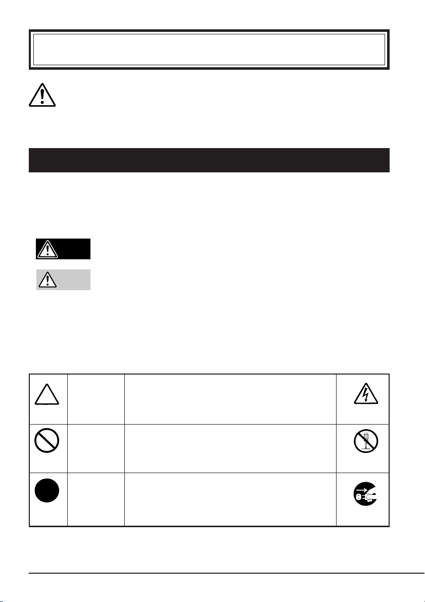
SAFETY INDICATIONS
This User’s Guide describes the device components with possible danger, hazards that
may be caused by ignoring warnings, and preventive actions against such hazards.
Components with possible danger are indicated with a warning label placed on or around
them. In the User’s Guide or warning labels, “WARNING” or “CAUTION” is used to
indicate a degree of danger. These terms are defined as follows:
Failure to heed this sign could result in serious
Warning
Caution
injury or death.
Failure to heed this sign could result in personal
in-jury or damage to properties.
Precautions and notices against hazards are presented with one of the follow-ing three
symbols. The individual symbols are defined as follows:
Attention
Prohibited
Action
Mandatory
Action
This symbol indicates the presence of a
hazard if the instruction is ignored. An
image in the symbol illustrates the hazard
type.
This symbol indicates prohibited actions.
An image in the symbol illustrates a
particular prohibited action.
This symbol indicates mandatory actions.
An image in the symbol illustrates a
mandatory action to avoid a particular
hazard.
(sample)
(Electric shock)
(sample)
(Do not
disassemble)
(sample)
(Disconnect the
power cord)
Safety Consideration 61
Page 63

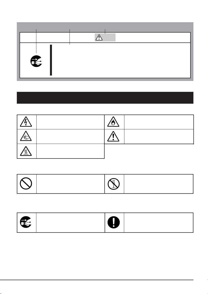
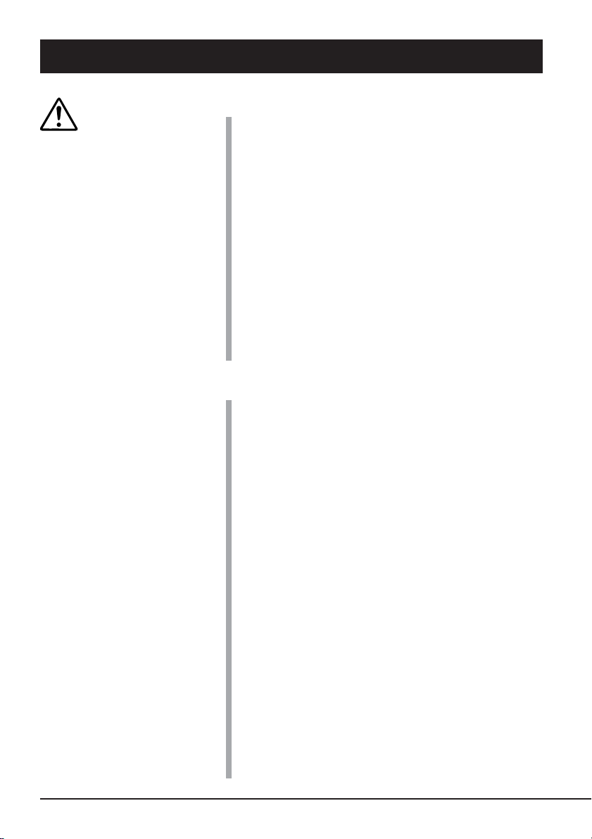
(Sample)
A symbol for
arousing attention
A content of
possible danger
A term indicating a
hazard level
Warning
Do not install the device while the power is turned on.
Unplug the AC power cord from the main power source when
installing/ uninstalling the device to/from basic processing unit
or connect it with the enclosure. Failure to follow this warning
may cause an electric shock.
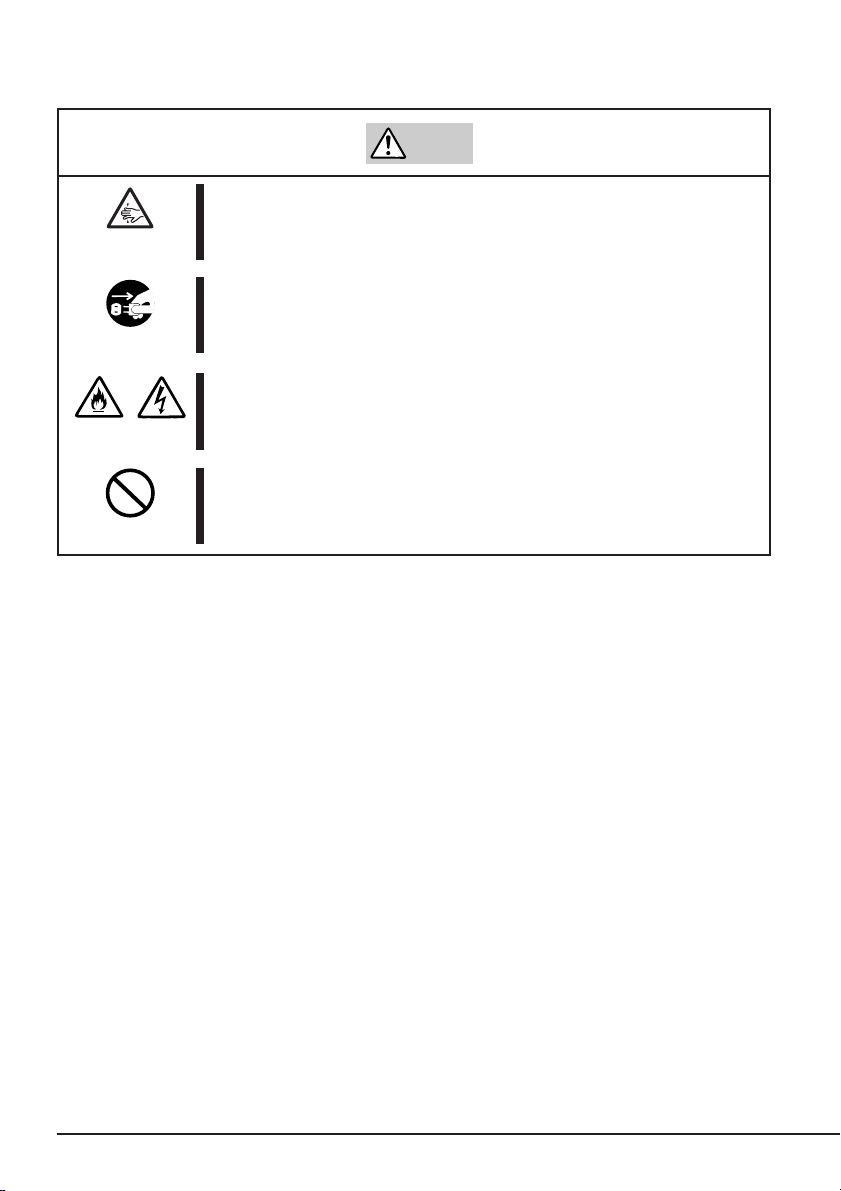
SYMBOLS USED IN THIS USER’S GUIDE AND WARNING LABELS
Attention
Indicates that improper use
may cause an electric shock.
Indicates that improper use
may cause fingers to be caught.
Indicates that improper use
may cause personal injury.
Indicates that improper use
may cause fumes or fire.
Indicates a general notice or
warning that cannot be
specifically identified.
Prohibited Action
Indicates a general prohibited
action or warning that cannot
be specifically identified.
Mandatory Action
Unplug the power cord.
Otherwise, an electric shock or
fire may be caused.
62 Safety Consideration
Do not disassemble, repair, or
modify the device. Otherwise,
an electric shock or fire may be
caused.
Indicates a general mandatory
action or warning that cannot
be specifically identified.
Page 64

SAFETY NOTES
This section provides several precautions to enable you to use the product safely and
correctly and to prevent injury and property damage. Read this section carefully to ensure
proper and safe use of the product. For symbols, see “SAFETY INDICATIONS” provided
earlier.
General Attention
Warning
Do not use in life-critical applications or applications
requiring high reliability.
This device is not intended for integration with or control of
facilities or equipment that may affect human life or that require a
high degree of reliability, such as medical equipment, nuclear
power facilities, aerospace instruments, and transportation
equipment. The manufacturer does not assume any liability for
accidents resulting in injury or death, or for any damages to
property that may occur as a result of using this device in such
facilities, equipment, or control systems.
Do not use the Built-in AIT if any smoke, odor, or noise is
present.
If smoke, odor, or noise is present, immediately turn off the
POWER switch and disconnect the power plug from the outlet,
then contact your sales agent. Using the Built-in AIT in such
conditions may cause a fire.
Keep needles or metal objects away from the Built-in AIT.
Do not insert needles or metal objects into ventilation holes in
the Built-in AIT. Failure to follow this warning may cause an
electric shock.
Caution
Keep water or foreign matter away from the Built-in AIT.
Do not let any kind of liquid (water etc.) or foreign matter
(e.g.,pins or paper clips) enter the Built-in AIT. Failure to follow
this warning may cause an electric shock, a fire, or a failure of
the Built-in AIT. When such things accidentally enter the Built-in
AIT, immediately turn off the power and disconnect the power
plug from the outlet. Do not disassemble the Built-in AIT. Contact
your sales agent.
Safety Consideration 63
Page 65

Attention to Power or Power Cord
Warning
Do not hold the DC cable with a wet hand.
Do not disconnect/connect the cable while your hands are wet.
Failure to follow this warning may cause an electric shock.
Caution
Do not install the device while the power is turned on.
Unplug the AC power cord from the main power source when
installing/ uninstalling the device to/from basic processing unit or
connect it with the enclosure. Failure to follow this warning may
cause an electric shock.
Insert the DC cable into the outlet as far as it goes.
Heat generation resulting from a halfway inserted DC cable
(imperfect contact) may cause a fire. Heat will also be generated
if condensation is formed on dusty blades of the halfway inserted
cable, increasing the possibility of a fire.
Do not connect the Built-in AIT by unspecified cabling.
Connecting or cabling with DC cable should be done in
accordance with the procedure specified in the User’s Guide.
Unspecified connecting or cabling may cause an electric shock
or a fire.
Do not use any damaged power cord.
If the power cord is damaged, immediately replace it with a new
part of same type. Do not repair the damaged section for reuse.
Otherwise, the section repaired with vinyl tape or the like will be
overheated to cause an electric shock or a fire.
Use the authorized cable only.
Use only the specified cable when connecting the Built-in AIT
with a basic processing unit. Use of an unspecified cable or
connection by unspecified cabling may cause a fire.
64 Safety Consideration
Page 66

Attention to Installing, Moving, Storing, Connection
Caution
Do not close the ventilation hole.
Do not close the ventilation hole in the front side of the Built-in
AIT. Otherwise, Its internal temperature will rise to cause
malfunctions or a fire.
Do not connect/disconnect the interface cables before
unplugging the power plug.
Before connecting/disconnecting the interface cables, disconnect
the power plug of the main power unit from the outlet. If the
power is off but the power plug is still connected, you may get an
electric shock.
Do not use the unspecified interface cables.
Use only the cable authorized by NEC and locate the device and
connector before connection. Use of an unauthorized cable or
displaced connection may cause a short circuit, resulting in a fire.
When handling or connecting the interface cables, keep the
notes as follows:
• Do not tread on cables.
• Do not load on the cable.
• Insert the cable connector as far as it goes.
• Do not use damaged cables.
• Do not use damaged connectors.
• Make sure that screwing or the like be done firmly.
Do not use or store this product in corrosive environment.
Avoid the usage or storage of this product in an environment
which may be exposed to corrosive gases, such as those
including but not limited to :
sulfur dioxide, hydrogen sulfide, nitrogen dioxide, chlorine,
ammonia and/or ozone.
Avoid installing this product in a dusty environment or one that
may be exposed to corrosive materials such as sodium chloride
and/or sulfur.
Avoid installing this product in an environment which may have
excessive metal flakes or conductive particles in the air.
Such environments may cause corrosion or short circuits within
this product, resulting in not only damage to this product, but
may even lead to be a fire hazard.
If there are any concerns regarding the environment at the planned
site of installation or storage, please contact your sales agent.
Safety Consideration 65
Page 67

Caution
High temperature
Immediately after the server is powered off, its internal
components such as hard disks are very hot. Leave the server
until its internal components fully cool down before installing/
removing any component.
Attention to Handling or Maintenance
Warning
Do not disassemble, repair, or alter the Built-in AIT.
Never attempt to disassemble, repair, or alter the Built-in AIT on
any occasion other than described in this User’s Guide. Failure
to follow this instruction may cause an electric shock or a fire as
well as malfunctions of the Built-in AIT.
The following can be performed by the Built-in AIT user. Do not
perform any other type of disassembly than described here.
• Remove or install brackets
• Remove or install the DC signal cable
Do not handle while the power plug is connected.
Before handling or cleaning the Built-in AIT, disconnect the
power plug of the main power unit from the outlet. If the power is
off but the power plug is still connected, you may get an electric
shock.
Insert the cables into the connectors as far as it goes.
Heat generation resulting from a halfway inserted cables or
Interface cables (imperfect contact) may cause a fire. Heat will
also be generated if condensation is formed on dusty blades of
the halfway inserted cable, increasing the possibility of a fire.
66 Safety Consideration
Caution
Page 68

Attention to Operation
Do not insert your hands into the cartridge load
compartment.
Do not insert your hands into the cartridge load compartment.
Otherwise, the fingers will be caught/pinched by the Built-in AIT
to cause an injury.
Do not touch the Built-in AIT when it thunders.
If it starts thundering, do not touch any part of the Built-in AIT.
Failure to follow this warning may cause an electric shock or a
fire.
Keep away pets.
Keep away pets from the Built-in AIT. Insertion their hair or
excrements may cause a fire or an electric shock.
Do not use a cellular phone or a pager
Tu rn off the power of the cellular phone or a pager. Otherwise,
malfunction may be caused.
Warning
Safety Consideration 67
Page 69

For Correct Operation
To operate the Built-In AIT correctly, observe the following points. For considerations on handling
the AIT data cartridge, refer to the chapter “AIT Data Cartridge”.
• Set the Built-In AIT’s SCSI ID so that it will not duplicate with SCSI ID of other SCSI equip-
ment.
→ Otherwise, an operation error will occur.
• Do not turn off the basic processing unit when the TAPE MOTION LED on the front of the
Built-In AIT is blinking.
→ This may cause a machine failure or damage of backup data.
• Do not store the Built-In AIT in a place subject to corrosive gas, chemicals or splash of chemi-
cals.
→ A Built-In AIT part may be deformed or damaged and may not be able to operate correctly.
• Do not store the Built-In AIT in a place subject to strong vibrations.
→ This may cause a machine failure.
• As the data cartridge set in the Built-In AIT, use our “AIT Data Cartridge” (models: AIT-1,
AIT-1 Turbo, AIT-2 or AIT-2 Turbo).
→ If you use a data cartridge of other manufacturer, a read/write error may occur.
• Clean the Built-In AIT on a regular basis.
→ For details about cleaning the Built-In AIT, see “Cleaning” (page 101).
• When cleaning the Built-In AIT, use our “AIT Cleaning Cartridge”.
→ If you use a cleaner of other manufacturer, a machine failure may occur.
• Do not transport the Built-In AIT with a data cartridge inserted.
→ Shocks may damage the Built-In AIT and/or data cartridge.
• Eject the data cartridge when you are done performing a backup.
→ This may shorten the operational life of the data cartridge and/or cause malfunctions.
68 Safety Consideration
Page 70

Organization of the Instruction Manual
The instruction manual function as a guide that enables you to set up and use the N8151-54 BuiltIn AIT correctly. You can refer to this manual whenever you encounter a question or problem
during setup and daily operation.
The instruction manual consists of two chapters: the first covers the considerations on the safe use
of the Built-In AIT (setup, daily operation and maintenance) and the second covers the considerations on the safe use of the AIT data cartridge available on the Built-In AIT (operation and
maintenance).
Order of priority when the Built-In AIT is used for the first time
When the Built-In AIT is being used first time, refer to the instruction manual in the following
sequence to perform the setup after unpacking the driver.
1. Check the contents in the package. ....................... Package Contents (→P. 72)
2. Learn the operational precaution. ......................... Safety Consideration (→ P. 61 to 67)
3. Learn the parts of the Built-In AIT ....................... Part Name and Function (→ P. 76 to 77)
4. Set before installation. .......................................... Setup (→ P. 78 to 83)
5. Mount the drive in the basic processing unit. ....... Setup (→ P. 84 to 86)
6. Install the tape driver.
7. Learn how to handle the cartridge......................... AIT Data Cartridge (→ P. 103 to 108)
8. Set the cartridge. ................................................... Handling (→ P. 98 to 100)
9. Check the LED indication..................................... Handling (→ P. 101)
10. Clean the Built-In AIT. ......................................... Cleaning (→ P. 101 to 102)
*
........................................... Installing the tape driver (→ P. 87 to 96)
*
Only necessary when using the Windows 2000, Windows XP, or Windows Server 2003
backup feature.
For details on data storage methods and settings, such as data save format, refer to
the instruction manual provided with the backup software.
Safety Consideration 69
Page 71

Symbols Used in This Text
The following symbols are used in this text to indicate cautions and notes concerning the operation
of this device. (Refer to the beginning of this document for an explanation of the symbols used for
safety-related cautions.)
Important
Hint
✎
This symbol indicates important information concerning the handling of the
device or the operation of the software.
Indicates useful information and operational help.
70 Safety Consideration
Page 72

Others
Transfer to a third party
If you transfer or sell the Built-In AIT to a third party, make sure that the transfer or sale satisfies
the following.
When you transfer or sell the Built-In AIT, be sure to include the instruction manual.
Other accessories
Accessories accompanying the Built-In AIT are necessary during setup and other procedures,
therefore be sure to include them.
Important
Data on tape
It is the responsibility of the transferring or selling party to dispose of important data stored on
tape (such as sales forecasts or budgets) to avoid divulging it to a third party. To this end, we
strongly recommend that you dispose of all backed up data through your backup software before
transferring or selling the unit. For details about how to perform this operation, refer to your
backup software documentation. NEC does not accept responsibility for information leaks to third
parties.
Supplied software
When you transfer or sell the Built-In AIT, make sure that you include all the software supplied
with the unit and do not keep any copies of said software. Also, make sure that the transfer
satisfies the conditions specified in each supplied software user license agreement.
Disposal of consumed parts and equipment
For the disposal of the Built-In AIT and its cartridge, observe the waste disposal rules of your local
government. For details, contact the local government office.
Product life
The life of the N8151-54 are five years.
Safety Consideration 71
Page 73

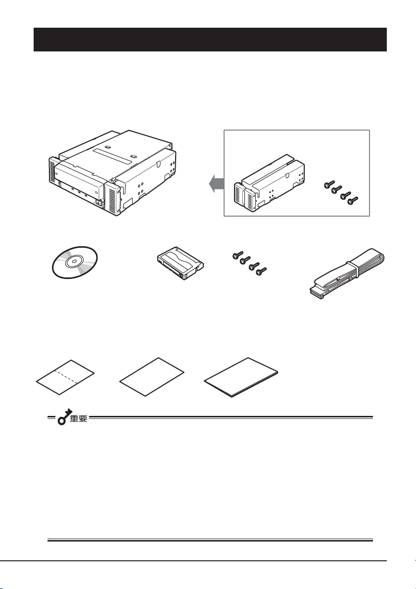
Package Contents
Many accessories are included with the Built-In AIT in the N8151-54 Built-In AIT. Verify the
packed contents with the part list given below and ensure that all the components and parts are
present. Also, check that each item is undamaged. If a component or part is missing or damaged,
contact your dealer.
N8151-54
The brackets (2) are shipped screwed (4).
Cleaning cartridge
Instructions on handling
the AIT unit
Important
Screws (4)
* Only use when
installing the device
on the basic
processing unit.
Startup Guide
CD-ROM
(User’s Guide, Device driver)
SCSI cable
* Used to connect to the Built-
In AIT when using the
optional SCSI board
(N8103-75F).
• Locking parts contained in the package or box will be required when removing the Built-In AIT
for transportation. Store them securely.
• Depending on the environment connected to, some parts may not be usable. However, when
the environment is changed, these parts may become usable, therefore store them securely.
•To ensure that you do not lose the device driver, make sure that you back up the supplied CDROM. Once you do, store the master disk in a safe location and use the copy.
72 Safety Consideration
Page 74

Table of Contents
Trademarks ............................................................. 60
Safety
Considerations
- Must Read -
Built-in AIT
SAFETY INDICATIONS ....................................... 61
SYMBOLS USED IN THIS USER’S GUIDE AND
WARNING LABELS ........................................... 62
SAFETY NOTES ................................................... 63
For Correct Operation............................................. 68
Organization of the Instruction Manual.................. 69
Order of priority when the Built-In AIT is used
for the first time ............................................. 69
Symbols Used in This Text ............................... 70
Others ..................................................................... 71
Transfer to a third party .................................... 71
Disposal of consumed parts and equipment ..... 71
Product life........................................................ 71
Package Contents.................................................... 72
Features................................................................... 75
Usable Cartridges and Compatibility Chart ........... 75
Part Name and Function ......................................... 76
Front .................................................................. 76
Front (when the dust cover is open).................. 76
Rear ................................................................... 77
Bottom .............................................................. 77
Setup ....................................................................... 78
Removing and installing the brackets ............... 78
Setting the Built-In AIT - Setting with the jumper
pins - .............................................................. 80
Setting the Built-In AIT - Setting with the DIP
switch - .......................................................... 82
Mounting on the basic processing unit ............. 84
Installing the tape device driver ........................ 87
Using the ASR function.......................................... 97
Handling ................................................................. 98
Setting the AIT data cartridge........................... 98
Ejecting the AIT data cartridge......................... 99
LED indication................................................ 101
Reading/writing data ....................................... 101
Table of Contents 73
Page 75

Cleaning................................................................ 101
Cleaning the read/write head .......................... 101
Cleaning the Built-In AIT ............................... 102
AIT Data Cartridge
Data Cartridge Part Name and Function............... 103
Operation, Storage and Transportation
Requirements...................................................... 104
Label ..................................................................... 104
Label paste position ........................................ 104
Precautions on entry to label........................... 105
Write-protect......................................................... 105
Precautions on Handling....................................... 106
Operational precautions .................................. 106
General precautions ........................................ 106
Usage Inhibition Standard .................................... 107
Service Life .......................................................... 107
Storing Important Data ......................................... 108
Managing 3-generation Data ................................ 108
Data cartridge storage ........................................... 108
Establishing backup and disaster
recovery procedures ........................................... 108
Specifications........................................................ 109
Customer’s Application Sheet .............................. 111
Troubleshooting Checklist.................................... 112
74 Table of Contents
Page 76

Built-in AIT
This chapter explains setup, installation and daily operation of the Built-In AIT.
Features
This unit has the following features:
• You can record large amounts of data cartridges using AIT (Advanced Intelligent Tape) format.
• When using the data compression function, the following volumes can be stored on a data
cartridge.
Tape standard Tape length Memory capacity (GB)
AIT-1 Turbo 186 m Approx. 80 GB
AIT-1 230 m Approx. 70 GB
170 m Approx. 50 GB
AIT-2 Turbo 186 m Approx. 160 GB
AIT-2 230 m Approx. 100 GB
170 m Approx. 72 GB
• The basic processing unit automatically determines whether data recorded on the AIT data
cartridges is compressed. It can also read data recorded on AIT data cartridges with conventional AIT drives.
• Upon shipment, the 5.25-in device comes with brackets installed at both ends of the drive.
Removing the brackets makes the drive only a 3.5-in device.
5.25-in device, installed (Upon shipment) 3.5-in device, installed
Usable Cartridges and Compatibility Chart
Please use Sony AIT data cartridges only with this unit. Using other types of AIT data cartridges
may cause read and write errors.
Built-in AIT 75
Page 77

The following AIT cartridges are compatible with this drive:
Tape standard Read from Write to Tape length
AIT-2 Turbo Yes Yes 186 m
AIT-2
Ye s Ye s
230 m
170 m
AIT-1 Turbo Yes Yes 186 m
AIT-1
Ye s Ye s
230 m
170 m
Part Name and Function
The Built-In AIT and magazine have the following parts and functions.
Important
The part names, functions, and settings of the installed 5.25-in device and installed 3.5-in device
(drive only) are the same. (For clarity, we use the 5.25-in device in the explanations below.)
Front
1
2
56 4 3
7
Front (when the dust cover is open)
8
1
1 Dust cover
Protects the cartridge slot against
dust. (→ P. 98)
2 Ventilation holes
(The drive does not have ventilation
holes.)
3 EJECT button
Press this button when ejecting a data
cartridge. (→ P. 99)
4 REPLACE TAPE LED
LED that shows that the AIT data
cartridge needs to be replaced.
(→ P.101)
5 CLEANING REQUEST LED
LED that shows the Built-In AIT
cleaning status. (→ P. 101)
6 TAPE MOTION LED
LED that shows the AIT data cartridge
status. (→ P. 101)
7 Brackets
8 Cartridge slot
Slot in which the AIT cartridge is set.
(→ P. 98)
76 Built-in AIT
Page 78

Rear
4
1 Power connector
Connect the Built-In AIT’s built-in
power cable. (→ P. 85)
2 Jumper pin
Pins which set the Built-In AIT
(→ P. 80)
3 SCSI connector
Connect the Built-In AIT’s built-in
SCSI cable. (→ P. 85)
4 Fa n
Bottom
3
2
1
12345678
ON
1
1 DIP switch
Switches which set the Built-In AIT
(→ P. 82)
Built-in AIT 77
Page 79

Setup
The procedure up to installation of the Built-In AIT to the “basic processing unit” is explained in
the following.
Removing and installing the brackets
When you want to use the Built-In AIT as a 3.5-in device, you need to remove the left and right
brackets.
To remove the brackets
Using a Phillips screwdriver, remove the screws, and then the brackets.
Important
• Make sure that you store the brackets and screws in a safe place.
• Only use these screws when installing the brackets. They are metric
screws (length: 5.0 mm; length below washer: 4.0 mm). Using longer
screws could result in damage.
metric screw
4.0 mm
78 Built-in AIT
Page 80

To install the brackets
Align the Built-In AIT screw holes with the far end of the bracket adjustable screw holes. With a
Phillips screwdriver, tighten the screws.
Built-in AIT 79
Page 81

Setting the Built-In AIT - Setting with the jumper pins -
You can change the following settings with the jumper pins on the rear of the Built-In AIT.
• SCSI ID (factory-set to “ID4”)
• Parity function (factory-set to “Enabled”)
SCSI ID (pin 0 to 3 from right)
Unused (NC)
Parity (PD)
Hint
✎
Hint
✎
“With jumper plug” means a status that the jumper plugs are attached to two pins.
“Without jumper plug” means a status that no jumper plug is attached to either pin or it is
attached to one of two pins.
“Without jumper plug” means that one
jumper plug is attached to one of the two
pins, or that the jumper plug has been
removed altogether. If you remove the
jumper plug, make sure you store it in a
safe place.
80 Built-in AIT
Page 82

Setting SCSI ID
Set SCSI ID which is used by the Built-In AIT. Use four jumper pins, pin 0 to pin 3, on the rear of
the Built-In AIT.
Pin 3 (Factory-set to “Without jumper plug)
Pin 2 (Factory-set to “With jumper plug”)
Pin 1 (Factory-set to “Without jumper plug”)
Pin 0 (Factory-set to “Without jumper plug”)
Important
Check that the Built-In AIT’s SCSI ID is not duplicated with SCSI ID of other SCSI device.
SCSI ID Pin 3 Pin 2 Pin 1 Pin0
0 ✕✕✕✕
1 ✕✕✕❍
2 ✕✕❍✕
3 ✕✕❍❍
*1
4
5 ✕❍✕❍
6 ✕❍❍✕
*2
7
8 ❍ ✕✕✕
9 ❍✕✕❍
10 ❍✕❍✕
11 ❍✕❍❍
12 ❍❍✕✕
13 ❍❍✕❍
14 ❍❍❍✕
15 ❍❍❍❍
✕❍✕ ✕
✕ ❍❍❍
❍ : With jumper plug
✕ : Without jumper plug
*1
: Factory-set value
*2
: Do not set SCSI ID to ID7.
Built-in AIT 81
Page 83

Setting the parity function
Set the parity function using the leftmost jumper pin on the rear of the Built-In AIT.
The parity function is “Enabled” when setting “Without jumper plug” (factory-set value). The
parity function is “Disabled” when setting “With jumper plug”.
PD (Factory-set to “Without jumper plug”)
Important
For better reliability, use with “Enabled (Without jumper plug)”.
Setting the Built-In AIT - Setting with the DIP switch -
The DIP switch on the bottom of the Built-In AIT enables you to change the following settings.
• Terminator Power (Terminator power supply) (Factory-set to OFF)
• DC Control (1) (Data compression setting) (Factory-set to ON)
• DC Control (2) (Data compression setting) (Factory-set to OFF)
82 Built-in AIT
ON
12345678
Switches 1 to 4: Unused
Switch 5: Terminator Power
Switch 6: Unused
Switch 7: DC Control (1)
Switch 8: DC Control (2)
Page 84

Setting terminator power - Terminator Power -
Set whether terminator power is supplied to the SCSI bus or not.
Use Switch 5. Setting Switch 5 to ON will supply terminator
power; setting Switch 5 to OFF (factory-set to OFF) will not
supply terminator power.
Important
When the Built-In AIT is equipped with the N8541-28F/N8141-28AF device expansion unit and
you want to use the slaved power feature, leave Switch 5 to OFF.
12345678
Setting data compression - DC Control (1) -
Set whether the Built-In AIT’s data compression function is
enabled or disabled.
Use Switch 7. Setting Switch 7 to ON (factory-set to ON) will
enable the data compression function; setting Switch 7 to OFF will
12345678
disable the terminator data compression function.
Setting data compression - DC Control (2) -
Set whether control of data compression from the backup software
is enabled or disabled.
Use Switch 8. Setting Switch 8 to ON will disable control of data
compression from the backup application; setting Switch 8 to OFF
(factory-set to OFF) will enable control of data compression from
the backup software.
12345678
ON
ON
ON
Built-in AIT 83
Page 85

Mounting on the basic processing unit
Caution
Turn off the power before installing or removing the device
Always be sure to turn off the main power and unplug the power cord from the
AC outlet before installing/removing this device or connecting any cables.
There is a risk of electric shock if this device in installed or removed or if any
cables are connected while the power cord is still plugged into an AC outlet.
The procedure for installing the drive in a server is as follows.
Hint
✎
Some servers require the rails to be used. For details on how to install the rails, refer to the
server's operating manual.
1 Install the Built-In AIT as shown here.
Important
• When using the rails with this
device, use the screw holes in the
front cover illustrated in Fig. 1 (see
Fig. 2). (Perform the same operation
on the opposite side. Secure two
screws on each side, four screws
total.)
In some cases the rails may extend
all the way to the front cover
molding. This causes no problems.
(The shape of the rails varies
according to the model of the
device.)
84 Built-in AIT
Fig. 1
Front cover
Screw hole
Fig. 2
Front cover
Rail
Page 86

Front cover
Rail
• The screws needed with the 5.25-in and 3.5-in devices are the same.
• Always use the screws that are provided with this device. The screws that
are provided with this device are metric screws (length: 5.0 mm; length
below washer: 3.5 mm). Using screws that are longer than the screws that
are provided with this device could result in damage to the device.
Caution
Do not use any damaged power cord.
If the power cord is damaged, immediately replace it with a new part of same
type. Do not repair the damaged section for reuse. Otherwise, the section repaired
with vinyl tape or the like will be overheated to cause an electric shock or a fire.
Fig. 3
3.5 mm
metric screw
2 Connect the cables to the drive as
shown here.
Important
• Except as noted below, use the SCSI cable provided with the Built-In AIT when connecting it to
the N8103-75F SCSI controller. Further, do not use the provided SCSI cable with any controller
other than the N8103-75F.
Some units may not be able to use the SCSI cable provided with the Built-In AIT. In that case,
use the SCSI cable that is provided with these units.
• Confirm the SCSI ID and other settings before installation.
• The factory default setting of the SCSI ID is 4. Make sure this ID is not used by any other
device in the system.
• This unit does not have a built-in terminator. When connecting this unit to the last terminal of
the SCSI bus terminal, attach a terminator to the end of the SCSI cable.
DC power cable
(unused power
supply connector in
the computer)
SCSI interface cable
Built-in AIT 85
Page 87

3 Attach the cover to the basic processing unit. Plug the power cable to the outlet.
4 Turn on the basic processing unit.
5 When the SCSI bus can be set on the side of the basic processing unit, set the following on the
Built-In AIT.
• Transfer rate : 160 Mbyte/second (max., synchronous)
• Data bus width : 16 bits (Ultra Wide SCSI, LVD/SE)5
• DISCONNECT/RECONNECT function : Enable
This device has a maximum transfer rate of 160 Mbyte/second. Set the transfer rate to 160
Mbyte/second on Built-In AIT units that support it, and to the next greatest transfer rate under
160 Mbyte/second on those that do not.
When using the N8103-75F SCSI board, set to 160 Mbyte/second.
Also, when the N8141-28AF expansion unit is connected, even if the transfer rate of the BuiltIn AIT is 160 Mbyte/second, set it to the next greatest transfer rate under 160 Mbyte/second.
For details, see the instruction manual provided with the basic processing unit.
Important
Set the maximum transfer rates as follows according to the number of devices connected to the
bus and the SCSI cable length.
The following are standard values.
If you have other specifications at your disposal, use them over the ones below.
SCSI ID
Ultra 160 SCSI 160 16 4 12 16
Ultra 2 Wide SCSI
Ultra Wide SCSI 40 16 3 - 4
Ultra Wide SCSI 40 16 1.5 - 8
Ultra Wide SCSI 40 16 - 3 16
Fast Wide SCSI 20 16 3 3 16
Wide SCSI 10 16 6 3 8
Maximum transfer Data bus Maximum cable
rate (Mbyte/s) width (bit) length (m) of devices
Single-ended LVD*
80 16 - 12 16
Maximum number
number of devices)
* When the SCSI host and all devices connected to the same bus are LVD-compatible.
86 Built-in AIT
(SCSI host +
Page 88

Installing the tape device driver
Only install the device drive if you intend to use Windows 2000 Backup, Windows XP Backup, or
Windows Server 2003 Backup (found in their respective System Tools folder).
Install the device driver in the basic processing unit with the supplied floppy disk. Prepare the
floppy disk beforehand.
For Windows 2000 Users
1 Click the [Start] button, point to [Settings], click [Control Panel], and then double-click
[System].
The [System Properties] dialog box appears.
2 Click the [Hardware] tab, then click the [Device Manager] button.
The [Device Manager] window appears.
3 Make sure that [SONY SDX-550V
SCSI Sequential Device] appears in
[Other devices], and then double-click
it.
The [SONY SDX-550V SCSI Sequential Device Properties] dialog box
appears.
Built-in AIT 87
Page 89

4 Click the [Driver] tab, then click the
[Update Driver] button.
The [Upgrade Device Driver Wizard]
appears.
5 Click the [Next] button.
The [Install Hardware Device Drivers]
screen appears.
6 Select [Search for a suitable driver for
my device (recommended)], then click
the [Next] button.
The [Locate Driver Files] screen
appears.
Insert the floppy disk provided.
88 Built-in AIT
Page 90

7 Select the [Floppy disk drives] check
box, then click the [Next] button.
The basic processing unit starts
searching for driver files, then the
[Driver Files Search Results] screen
appears.
8 Make sure that
“a:\win2000\32\s32ait.inf” appears in
the [Driver Files Search Results]
screen, then click the [Next] button.
The [Completing the Upgrade Device
Driver Wizard] screen appears.
9 Click the [Finish] button.
Built-in AIT 89
Page 91

10 Make sure that the “Sony AIT 80 GB
SCSI Drive” appears in the [Device
Manager] window.
Installation of the tape device driver is now complete.
90 Built-in AIT
Page 92

For Windows XP Users
1 Click the [Start] button, click [Control Panel], then double-click [System].
The [System Properties] dialog box appears.
2 Click the [Hardware] tab, then click the [Device Manager] button.
The [Device Manager] window appears.
3 Make sure that [SONY SDX-550V
SCSI Sequential Device] appears in
[Other devices], and then double-click
it.
The [SONY SDX-550V SCSI Sequential Device Properties] dialog box
appears.
4 Click the [Driver] tab, then click the
[Update Driver] button.
The [Hardware Update Wizard]
appears.
Built-in AIT 91
Page 93

5 Select [Install the software automati-
cally (Recommended)], insert the
floppy disk provided, then click the
[Next] button.
The [Please select the best match for
your hardware from the list below.]
screen appears.
6 Select the hardware associated to
“a:\xp\32\s32ait.inf”, then click the
[Next] button.
The [Completing the Hardware Update
Wizard] screen appears.
7 Click the [Finish] button.
92 Built-in AIT
Page 94

8 Make sure that the “Sony AIT 80 GB
SCSI Drive” appears in the [Device
Manager] window.
Installation of the tape device driver is now complete.
Hint
✎
The device driver that you installed is enabled after you restart the system.
Built-in AIT 93
Page 95

For Windows Server 2003 Users
1 Click the [Start] button, point to [Control Panel], then click [System].
The [System Properties] dialog box appears.
2 Click the [Hardware] tab, then click the [Device Manager] button.
The [Device Manager] window appears.
3 Make sure that [SONY SDX-550V
SCSI Sequential Device] appears in
[Other devices], and then double-click
it.
The [SONY SDX-550V SCSI Sequential Device Properties] dialog box
appears.
4 Click the [Driver] tab, then click the
[Update Driver] button.
The [Hardware Update Wizard]
appears.
94 Built-in AIT
Page 96

5 Select [Install the software automati-
cally (Recommended)], insert the
floppy disk provided, then click the
[Next] button.
The [Please select the best match for
your hardware from the list below.]
screen appears.
6 Select the hardware associated to
“a:\w2k3\32\s32ait.inf”, then click the
[Next] button.
The [Completing the Hardware Update
Wizard] screen appears.
7 Click the [Finish] button.
Built-in AIT 95
Page 97

8 Make sure that the “Sony AIT 80 GB
SCSI Drive” appears in the [Device
Manager] window.
Installation of the tape device driver is now complete.
96 Built-in AIT
Page 98

Using the ASR function
When using the ASR (Automated System Recovery*) function in Windows, you must download
and install the device driver files from a floppy disk. Prepare a blank floppy disk, and copy the files
in the “DeviceDriver” folder on the supplied CD-ROM to the blank floppy disk.
Important
It is important to preserve the file paths
when creating the floppy disk. Copy the files
in the “DeviceDriver” folder so they appear
as shown below. (Do not include the
“DeviceDriver” folder itself.)
*ASR (Automated System Recovery)
Supported by Windows XP and Windows Server 2003, this function backs up the OS, system
state, hardware composition, and applications on your computer, allowing you to restore them in
one step when recovering from a crash. For more details on using this function, refer to the
manual for your OS and backup software.
Windows 2000 does not support the ASR function.
Built-in AIT 97
Page 99

Handling
The following explains how to handle the Built-In AIT.
Setting the AIT data cartridge
Important
• As the data cartridge to be set in the magazine, use our “AIT Data Cartridge”. If you use a data
cartridge of other manufacturer, a read/write error may occur.
• While setting the data cartridge, do not turn off the basic processing unit. This may cause a
malfunction or damage to data.
1 Turn on the basic processing unit. Check
that the drive’s REPLACE TAPE LED,
TAPE MOTION LED and CLEANING
REQUEST LED go off.
2 Open the dust cover.
3 Set the AIT data cartridge orienta-
tion as shown here and insert it into
the data cartridge slot.
By inserting the data cartridge to the
extent, it is automatically set in the
drive and the TAPE MOTION LED
lights.
4 Close the dust cover.
98 Built-in AIT
Page 100

Important
• Installing the dust cover
To avoid damaging the dust cover, it
is designed to be easy to install and
remove.To install the dust cover, hold
it slightly (as illustrated) and insert
the pins at both ends of the cover in
turn until you hear them clik.
Fig. 1
Ejecting the AIT data cartridge
Dust cover
1 Confirm that the TAPE MOTION LED is not blinking.
2 Pressing the EJECT button, Built-In
AIT starts rewinding the tape (this
may take a few minutes).
When the tape is completely
rewound, the data cartridge is
automatically ejected from the BuiltIn AIT.
Important
Depending on your backup software or operating system lock, you may not be able to eject the data
cartridge in the drive by pressing the EJECT button. Eject the data cartridge from the backup
software or wait some time and retry the EJECT button. If you are still unable to eject the data
cartridge, press and hold the EJECT button for 5 or 10 seconds to forcefully eject the data cartridge.
Built-in AIT 99
 Loading...