

NEC Solutions (America), Inc.
Visual Systems Division
61XR4 Installation Guide
61” Plasma Display Rev 1.2
Contents:
Product Description and Notes Page 1
Ventilation Requirements
Display Dimensions
Front, Top & Bottom
Rear
Left & Right Side
Display Dimensions w/Optional Speakers and Stand
Dimensions w/Optional Wall Mount
Dimensions w/Optional Wall Mount
Connections
Control Codes
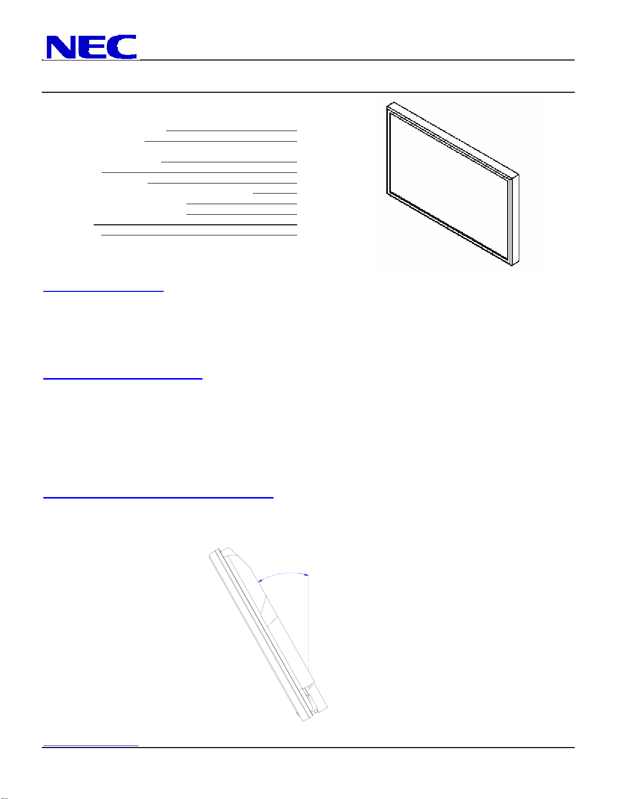
Product Description
Type: Plasma Display Screen Surface: Anti-Reflective
Resolution: 1365x768 Dimensions: 58.11”(W) x 34.64”(H) x 4.84”(D)
Aspect Ratio: 16:9 Weight: 134.5 lbs
Color Correction: NEC CCF (Capsulated Color Filter, in panel) FCC: Class B
and AccuCrimson (in front filter)
Notes
This document is intended to be used as a reference guide to supply useful information for a design or installation. It is not intended to
be a step-by step procedure for installation.
Any ceilings or walls must be strong enough to support the display and the installation must be in accordance with any local
building codes. All mounts should make secure contact to wood studs.
4:3 sources can be displayed on the 16:9 screen in either normal aspect ratio with bars on the left or right, or stretched horizontally to
fill the screen using the menus (see “Aspect Modes” in menus and user manual).
Distances are in inches, for millimeters multiply by 25.4.
Distances may vary ±5%.
Maximum Tilt Angles
Below are the maximum angles that the display can be tilted
Landscape 30°
Page 2
Page 3
Page 4
Page 5
Page 6
Page 7
Page 8
Page 9
Page 10
Max Tilt
www.visualsystems.com PX-61XR4 Page 1 of 10
NEC Solutions (America), Inc.
Visual Systems Division
61XR4 Installation Guide
61” Plasma Display Rev 1.2
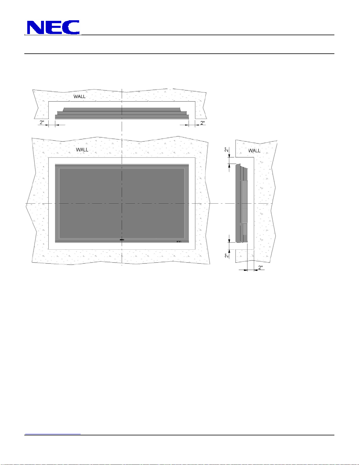
Ventilation Requirements (all models)
Dimensions below are minimum required for proper ventilation.
NOTE: The ventilation space should not be covered or closed off at the front of the opening. If for some reason the
opening needs to be covered, other means of ventilation will need to be incorporated into the design. Contact NEC for
design review and recommendations.
www.visualsystems.com PX-61XR4 Page 2 of 10
NEC Solutions (America), Inc.
Visual Systems Division
61XR4 Installation Guide
61” Plasma Display Rev 1.2
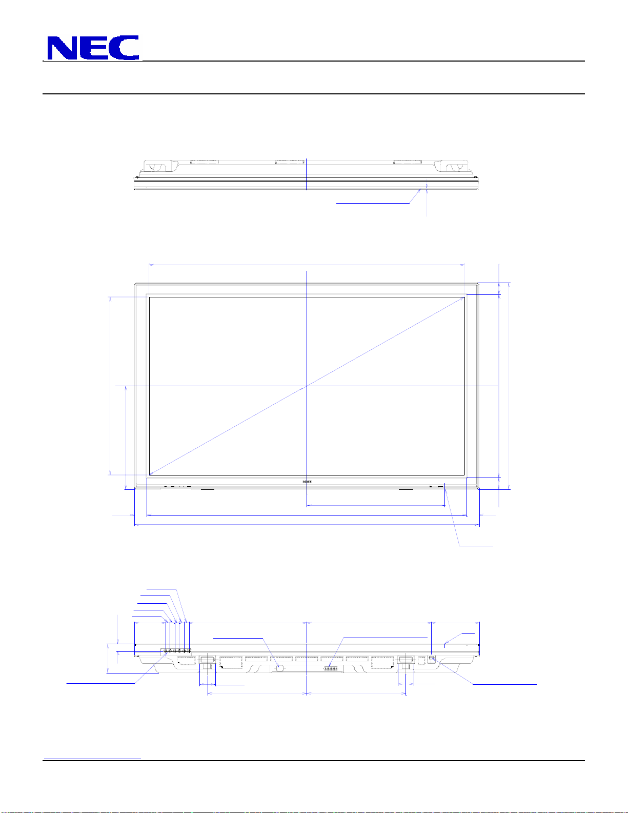
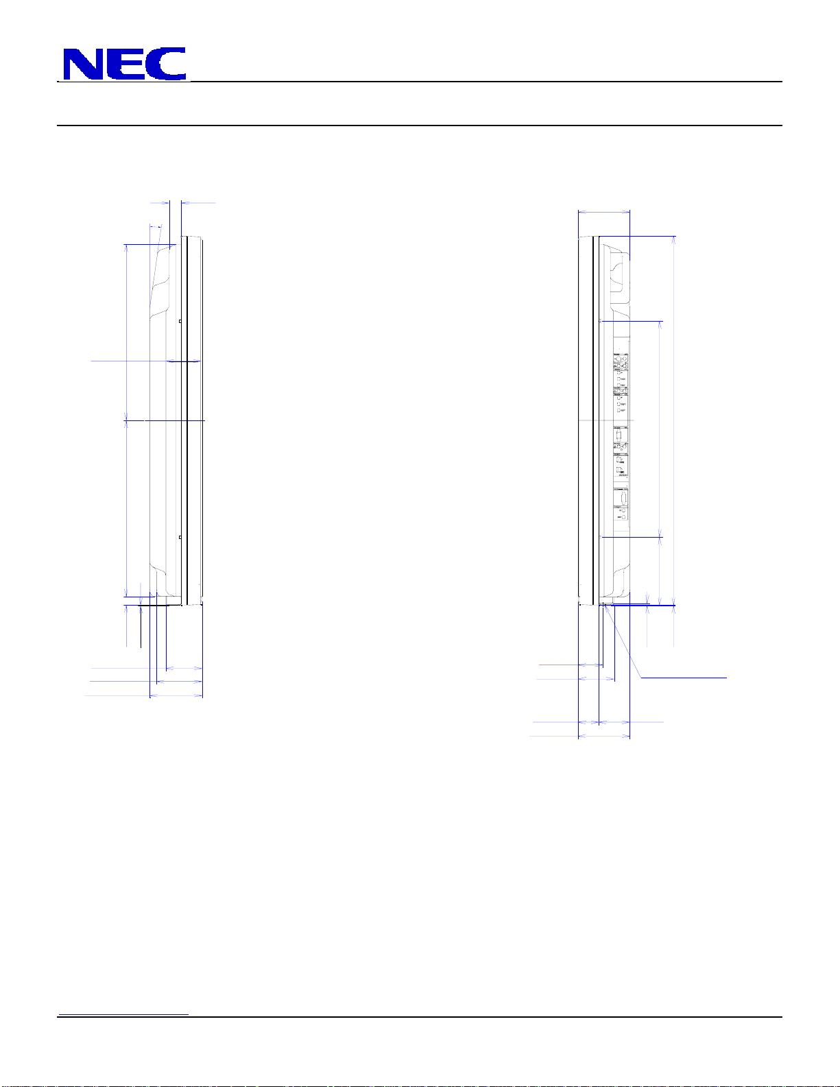
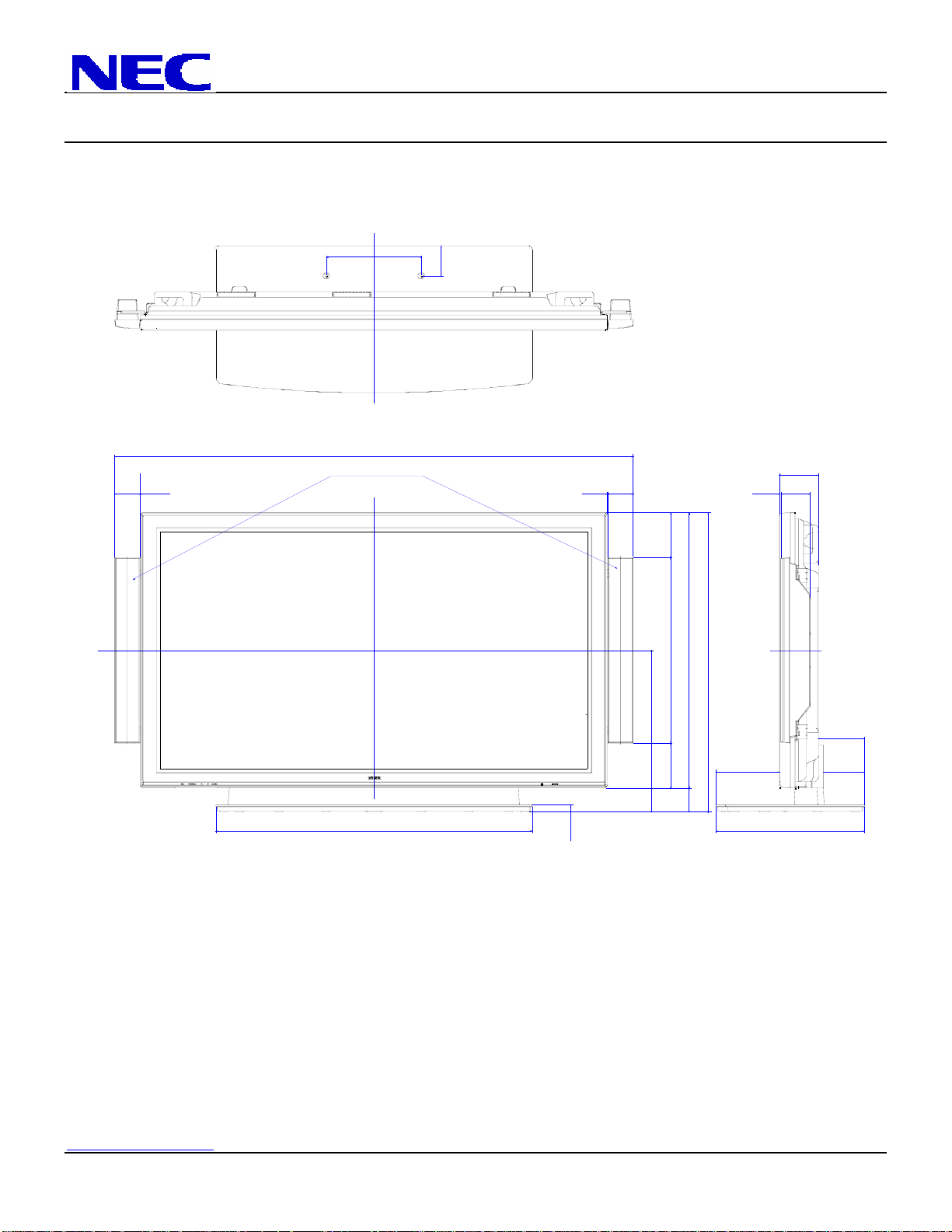
Display dimensions
29.92 (SCREEN AREA)
17.33
FILTER SURFACE
53.19 (SCREEN AREA)
1
6
0.33
1.92
30.78
34.64
2.05 54.02
1.20
4.84
CONTROL BUTTONS
0.78
0.78
0.78
0.78
5.23
0.78
19.88
AC INLET
2.75
16.73
58.11
23.33
21.05
SPEAKER TERMINAL
16.73
LED&IR
8.02
IR
2.75
1.92
2.05
POWER BUTTON
www.visualsystems.com PX-61XR4 Page 3 of 10
NEC Solutions (America), Inc.
Visual Systems Division
61XR4 Installation Guide
61” Plasma Display Rev 1.2
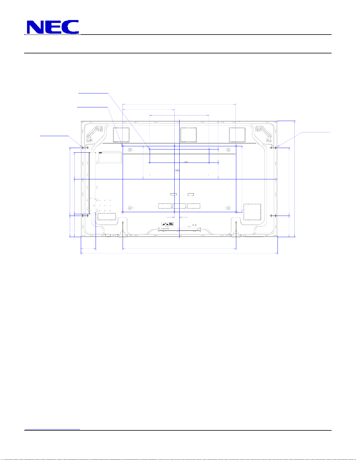
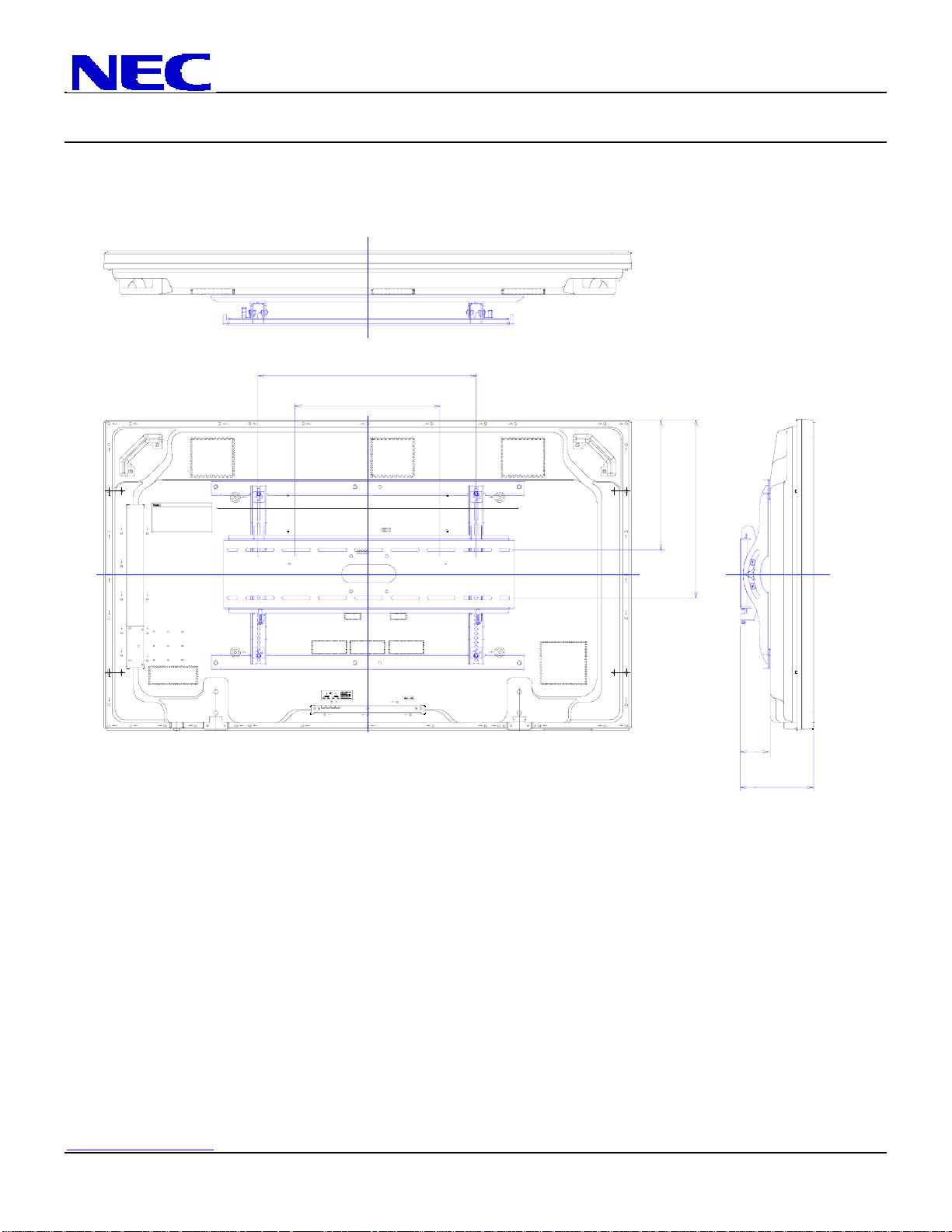
Display dimensions (cont.)
for PC
for Speaker
4-M4 Depth 10
4-M4 Depth 10
for Mount unit
20.28
6-M8 Depth 12
16.72
9.84
33.43
17.52
F
FF
8.42
4.02
4.88
19.69
FF
for Speaker
4-M4 Depth 10
FF
20.28
34.64
1.38
6.39
6 .89 10.42 7.91
4.41
33.47
58.11
F
FF
F
F
6.39
www.visualsystems.com PX-61XR4 Page 4 of 10
NEC Solutions (America), Inc.
Visual Systems Division
61XR4 Installation Guide
61” Plasma Display Rev 1.2
Display dimensions (cont.)
3.19
16.53
16.53
1.09
8
°
4.84
34.64
20.28 (for SPEAKER)
6 .39
0.05
0.20
POWER BUTTON
2.91
3.34
4.22
4.84
0.78
0.05
2.31
3 .34
1.92
4.84
www.visualsystems.com PX-61XR4 Page 5 of 10
NEC Solutions (America), Inc.
Visual Systems Division
61XR4 Installation Guide
61” Plasma Display Rev 1.2
Dimensions with optional speakers and stand
11.81
3.73
64.48
Optional Speakers
3.14
0.02 3.140.02
4.84
0.22 3.63
5.67
23.30
37.67
34.643.03
5.78
39.38
0.94
20.36
5.67
7.89 5.09
18.50
www.visualsystems.com PX-61XR4 Page 6 of 10
NEC Solutions (America), Inc.
Visual Systems Division
61XR4 Installation Guide
61” Plasma Display Rev 1.2
Dimensions with optional Wall Mount Kit (61WMK)
24.00
16.00
F
FF
FF
14.60
19.93
F
F
F
FF
F
F
3.35
8.14
www.visualsystems.com PX-61XR4 Page 7 of 10
NEC Solutions (America), Inc.
Visual Systems Division
61XR4 Installation Guide
61” Plasma Display Rev 1.2
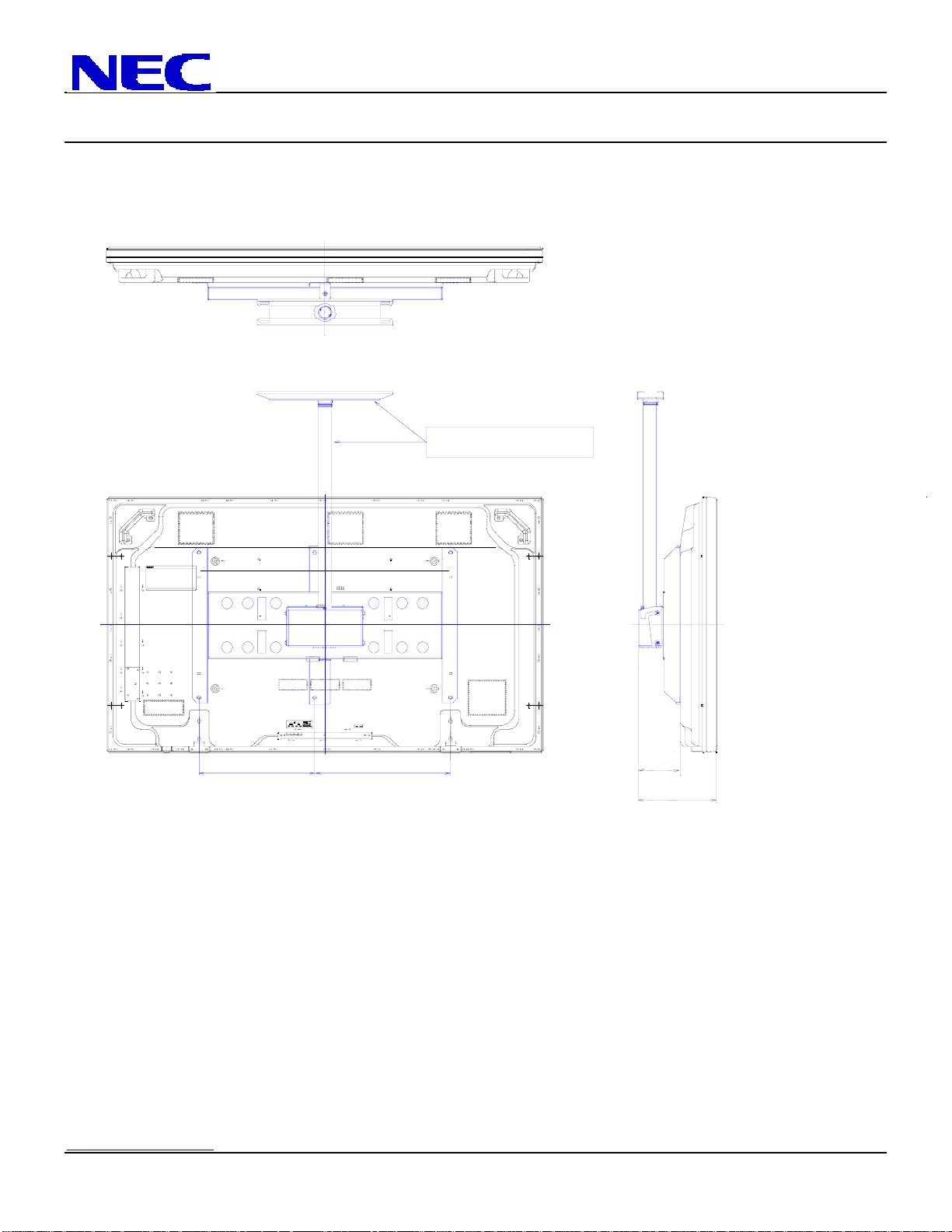
Dimensions with optional Ceiling Mount Kit (61CMK)
Note: Optional Accessories
not included with 4250CMK
F
F
15.49 18.05
F
FF
FF
FF
FF
F
5.70
10.45
www.visualsystems.com PX-61XR4 Page 8 of 10

NEC Solutions (America), Inc.
Visual Systems Division
61XR4 Installation Guide
61” Plasma Display Rev 1.2
Connections
Located at right side of display
Power Switch
AC inlet
Ext. Speaker Connections
Control Panel
www.visualsystems.com PX-61XR4 Page 9 of 10
NEC Solutions (America), Inc.
Visual Systems Division
61XR4 Installation Guide
61” Plasma Display Rev 1.2
Control Codes
Function Code Data
POWER ON 9FH 80H 60H 4EH 00H CDH
OFF 9FH 80H 60H 4FH 00H CEH
INPUT SWITCH VIDEO1 (RCA) DFH 80H 60H 47H 01H 01H 08H
VIDEO2 (S-Video) DFH 80H 60H 47H 01H 02H 09H
DVD1/HD1 DFH 80H 60H 47H 01H 05H 0CH
DVD2/HD2 DFH 80H 60H 47H 01H 06H 0DH
RGB1 (15pin HD) DFH 80H 60H 47H 01H 07H 0EH
DVD3/HD3 (HDMI) DFH 80H 60H 47H 01H 0EH 15H
DVD4/HD4 (HDMI) DFH 80H 60H 47H 01H 1AH 21H
AUDIO MUTE ON 9FH 80H 60H 3EH 00H BDH
OFF 9FH 80H 60H 3FH 00H BEH
PICTURE MODE NORMAL DFH 80H 60H 0AH 01H 01H CBH
THEAT.1 DFH 80H 60H 0AH 01H 02H CCH
THEAT.2 DFH 80H 60H 0AH 01H 03H CDH
DEFAULT DFH 80H 60H 0AH 01H 04H CEH
BRIGHT DFH 80H 60H 0AH 01H 05H CFH
SCREEN MODE: STADIUM DFH 80H 60H 51H 01H 02H 13H
ZOOM DFH 80H 60H 51H 01H 03H 14H
NORMAL DFH 80H 60H 51H 01H 04H 15H
ANAMORPHIC (FULL) DFH 80H 60H 51H 01H 05H 16H
2.35:1 DFH 80H 60H 51H 01H 0AH 1BH
AUTO PICTURE ON DFH 80H 60H 7FH 03H 03H 09H 00H 4DH
OFF DFH 80H 60H 7FH 03H 03H 09H 01H 4EH
CINEMA MODE ON DFH 80H 60H C1H 01H 01H 82H
OFF DFH 80H 60H C1H 01H 02H 83H
NOTE: Contact your NEC rep for codes not listed.
NOTE: Use a cross/reverse/null modem cable.
Cable Connection
Communication Protocol:
Interface: RS-232C Parity: Odd
Communication: Asynchronous Stop Bit: 1 bit
Baud Rate: 9600 bps Communication Code: Hex
Data Length: 8 bits
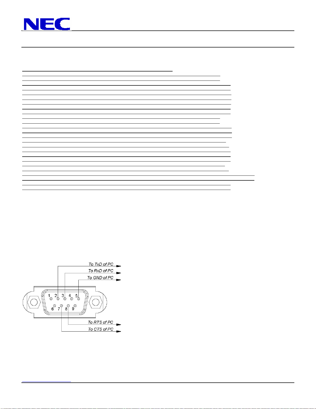
PC Control Connector (D-Sub 9P)
NOTE: If so Desired, jumper “Request to send” and “Clear to Send” together on both ends of the cable to simplify cable connection. These
connections are not required. The only connections required are pins 2 (RxD), 3 (TxD) and 5 (GND).
www.visualsystems.com PX-61XR4 Page 10 of 10
 Loading...