

Page 1

LA00 0605 D © 2007 Navm an New Zealand. All righ ts reser ved. Proprietary informatio n and specications subject to change without notice.
Jupiter 32
Miniature 20-channel
GPS receiver module
Integrator’s Manual
Related documents
• Jupiter 32 Product Brief LA000268
• Jupiter 32 Data Sheet LA000267
• Jupiter Development Kit Guide LA000645
• Low Power Operating Modes Application
Note LA000513
• Jupiter 32/30 Saving and retrieving
conguration data to Flash and Selectable
user proles Application Note LA000266
• Navman NMEA Reference Manual
MN000315
• SiRF Binary Protocol Reference Manual,
MN000314
Page 2

LA00 0605 D © 2007 Navm an New Zealand. All righ ts reser ved. Proprietary informatio n and specications subject to change without notice.
I
Contents
1.0 Introduction ....................................................................................................... 1
2.0 Hardware application information................................................................... 1
2.1 Electrical connections (SMT pad interface) .................................................................. 2
2.2 Typical application circuit ............................................................................................. 3
2.2.1 Power for receiver and active antenna ................................................................. 3
2.2.2 Grounding ............................................................................................................ 3
2.2.3 Decoupling ........................................................................................................... 5
2.2.4 Serial RS232 data level shifter ............................................................................. 5
2.3 PCB design recommendations ..................................................................................... 5
2.3.1 Choice of PCB stack up ....................................................................................... 5
2.3.2 Ground plane design ............................................................................................ 5
2.3.3 Decoupling components ...................................................................................... 6
2.3.4 Antenna connection ............................................................................................. 6
2.3.5 Design of 50 ohm microstrip antenna connection ................................................ 7
2.4 Antenna system design choices ................................................................................... 8
2.4.1 Antenna types ...................................................................................................... 8
2.4.2 Active antenna ..................................................................................................... 9
2.4.3 Passive antenna ................................................................................................... 9
2.4.4 Jupiter module used as a GPS sensor ................................................................10
2.4.5 DC supply protection for an active antenna ........................................................10
2.5 Jupiter adapter printed circuit board ............................................................................11
3.0 Packaging and delivery .................................................................................. 13
4.0 Manufacturing process recommendations .................................................. 15
4.1 Solder methods............................................................................................................15
4.1.1 Solder paste type .................................................................................................15
4.1.2 Solder paste mask size ........................................................................................15
4.1.3 Solder paste stencils ............................................................................................15
4.1.4 Reow prole recommendations .........................................................................15
4.1.5 Coating ................................................................................................................16
4.1.6 Post reow washing .............................................................................................16
4.1.7 Pre-baking ...........................................................................................................16
4.1.8 Rework .................................................................................................................16
4.1.9 Site Redress and Cleaning ..................................................................................17
4.1.10 Application of Solder Paste ................................................................................17
4.1.11 Placement and Attachment of the New Component ..........................................17
5.0 Software application information .................................................................. 17
5.1 Normal mode operation ...............................................................................................17
5.2 Power management ....................................................................................................17
5.2.1 Adaptive TricklePower mode ...............................................................................17
5.2.2 Push-to-Fix mode ...............................................................................................18
5.3 Serial I/O .....................................................................................................................18
5.3.1 Default settings ....................................................................................................18
5.3.2 NMEA input commands ......................................................................................18
5.4 Navman proprietary NMEA low power mode messages ............................................19
5.4.1 Low power conguration ......................................................................................19
5.4.2 Low power acquisition conguration ...................................................................19
5.5 Save and Retrieve Conguration Data to Flash ........................................................ 20
5.5.1 Writing to Flash ................................................................................................... 20
5.5.2 Retrieving from Flash ......................................................................................... 20
5.5.3 Reverting to default settings............................................................................... 20
5.6 Selectable User Proles .............................................................................................21
5.7 GPS x output .............................................................................................................21
5.8 Custom application software .......................................................................................21
6.0 Glossary and acronyms ................................................................................. 22
Page 3

LA00 0605 D © 2007 Navm an New Zealand. All righ ts reser ved. Proprietary informatio n and specications subject to change without notice.
II
Tables
Table 2-1: Jupiter 32 Module pad functions ........................................................................ 2
Table 2-2: Decoupling recommendations ........................................................................... 6
Table 2-3: PCB substrate thicknesses v track width .......................................................... 7
Table 2-4: Passive and active Patch antenna features ...................................................... 9
Table 2-5: Recommended antenna characteristics ...........................................................10
Table 2-6: Connector conguration ...................................................................................12
Table 5-1: Low power modes message values .................................................................19
Table 5-2: Low power acquisition input values ..................................................................19
Table 5-3: Actions based on signal state ......................................................................... 20
Figures
Figure 2-1: Jupiter 32 mechanical layout ............................................................................ 3
Figure 2-2: Basic Jupiter 32 application circuit ................................................................... 4
Figure 2-3: Example PCB layout for external active antenna ............................................. 4
Figure 2-4: Decoupling Capacitor Placement .................................................................... 5
Figure 2-5: Arrangement of active antenna and application board .................................... 6
Figure 2-6: Cross section of application board with passive patch antenna ...................... 7
Figure 2-7: PCB microstrip dimensions .............................................................................. 7
Figure 2-8: Simple current limiter circuit ............................................................................11
Figure 2-9: External Active Antenna Control and Current Limit circuit .............................. 11
Figure 2-10: Jupiter 32 adapter board ...............................................................................12
Figure 3-1: Moisture Barrier Bag Label .............................................................................13
Figure 3-2: Reel dimensions .............................................................................................13
Figure 3-3: Jupiter 32 Packaging ......................................................................................14
Figure 4-1: Sample Lead and Lead free reow prole ......................................................16
Page 4

LA00 0605 D © 2007 Navm an New Zealand. All righ ts reser ved. Proprietary informatio n and specications subject to change without notice.
1
1.0 Introduction
The Navman Jupiter 32 module is a complete GPS receiver designed for surface mount
assembly integration. The Jupiter 32 provides a simple, cost effective GPS solution for
application designers. Application integration will vary primarily with respect to antenna system
design and EMI protective circuitry.
The Jupiter 32 is the successor to the established Jupiter 30, being electrically compatible and
having a very small form factor. The provides an easy migration path for existing users requiring
very small packaging, low cost, high volume, greater sensitivity, lower power consumption and a
faster x.
Basic operation requires a power supply, GPS antenna system interface, relevant EMI
protection, and the design and layout of a custom PCB. This document outlines the following
design considerations and provides recommended solutions:
Hardware application information
This section introduces the system interface and provides the following physical specications:
a. electrical connections (SMT pad interface)
b. mounting (PCB pad layout dimensions)
c. manufacturing recommendations
d. application circuit interface
It also discusses fundamental considerations when designing for RF, and presents the antenna
system design overview. This covers the following topics:
a. PCB layout
b. antenna system design choices
A sample solution is presented and discussed. Due to the nature and complexity of GPS signals,
it is recommended that application integrators adhere to the design considerations and criteria
described in this document.
Software application information
This section provides answers to some common questions that might not have been covered in
the above topics.
2.0 Hardware application information
The Jupiter 32 module provide 34 Land Grid Array (LGA) pads for electrical connections. The
sections that follow introduce the physical and relative functional specications for application
integration.
Note: The electrical connections can carry very low level GPS signals at 1.57542 GHz. The
layout must be designed appropriately with consideration of the frequencies involved.
Page 5

LA00 0605 D © 2007 Navm an New Zealand. All righ ts reser ved. Proprietary informatio n and specications subject to change without notice.
2
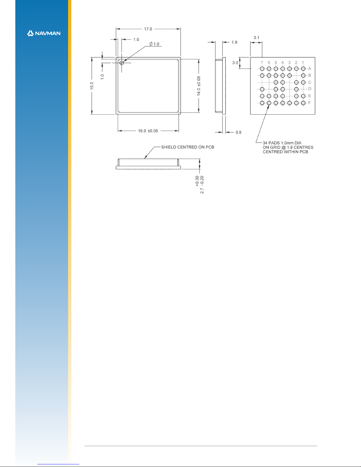
2.1 Electrical connections (SMT pad interface)
The round hole on the front label side of the chip locates pad A1. The pads are designated
A-F and 1-7. Details of the pad layout and numbering are shown in Figure 2-1.
Pad No Pad Names Type Description
A1 RF_IN I RF Input 50 ohm
A2 GND P RF signal ground return
A3 GND P ground
A4 VANT P active antenna power input
A5 GPIO15 I/O reserved
A6 GPIO14 I/O reserved
A7 RF_ON O output to indicate whether the RF section is
enabled (active high)
B1 GND P RF signal ground return
B3 VDD_BB P baseband power supply input for external
regulator build option - DO NOT CONNECT
B4 GPIO4 I/O reserved
B5 GPIO13 I/O reserved
B6 VDD_RTC P RTC power supply input for external regulator
build option - DO NOT CONNECT
B7 GPIO1 I/O reserved
C1 GND P ground
C2 TCXO_IN I TCXO input for external TCXO build option
- DO NOT CONNECT
C4 BOOT I active high to download ash rmware
C5 LNA _EN O external antenna enable, active high
D2 FACTORY USE ONLY reserved
D4 N_GPS_FIX O active low when 2D or 3D x data
available
D5 RXA I CMOS level asynchronous input for UART A
D7 TXA O CMOS level asynchronous output for UART A
E1 GND P ground
E2 GND P ground
E4 GPIO2 I/O reserved
E5 N_RESET I master reset, active low
E6 RXB I CMOS level asynchronous input for UART B
E7 1PPS O 1 pulse per second output 1µs wide
F1 PWRIN P 3.0 - 3.6 V main power supply input
F2 VBATT P 1.9 - 3.6 V backup battery input
F3 VCC_RF P RF power supply output for external regulator
option. Connect as per application circuit.
- Figure 2-2
F4 WAKEUP I Push-to-Fix wake-up, active high
F5 N_WAKEUP O low output indicates baseband is powered up
- DO NOT CONNECT
F6 TXB O CMOS level asynchronous output for UART B
F7 ECLK I external clock input, not used
Table 2-1: Jupiter 32 Module pad functions
Page 6
LA00 0605 D © 2007 Navm an New Zealand. All righ ts reser ved. Proprietary informatio n and specications subject to change without notice.
3
Figure 2-1: Jupiter 32 mechanical layout
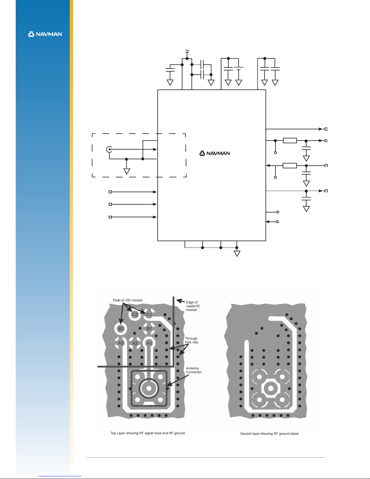
2.2 Typical application circuit
The schematic in Figure 2-2 (next page) represents a very basic application circuit, with simple
interfaces to the module. It is subject to variations depending on application requirements.
2.2.1 Power for receiver and active antenna
The receiver power connection requires a clean 3.3 VDC. Noise on this line may affect the
performance of the GPS receiver.
When an active antenna is used, the DC power is fed to it through the antenna coax. This
requires the user to apply the antenna DC voltage to pad A4 of the module.
A 2.85 V 30 mA supply is made available on pad F3 if the chosen antenna can accept that
voltage. This supply is under the command of the TricklePower energy control.
The source impedance of the power supply must be kept sufciently low. The capacitance of
the power supply and PCB track width determine the overall source impedance. If a passive
antenna is used, the supply must be able to provide a minimum of 100mA continuously with
minimal ripple as measured at the power input pin. This ripple requirement must be adhered
to for a larger current ow when an active antenna is used. In-rush current for some active
antennas have been measured as high as 70mA and may cause a dip in voltage or ripple.
Therefore, a low source impedance is important since the power to the Jupiter 32 must be
able to accommodate instantaneous currents in excess of 200mA.
2.2.2 Grounding
Separate analogue and digital grounds are not used. However, the antenna signal ground
uses a particular layout for optimum results. See Figure 2-3 (next page) and Section 2.3.5
for ground plane recommendations and for design considerations involving the antenna input
and the 50 ohm microstrip connection.
All dimensions in mm
Page 7
LA00 0605 D © 2007 Navm an New Zealand. All righ ts reser ved. Proprietary informatio n and specications subject to change without notice.
4
A1 RF_IN
C4 BOOT
F4 WAKEUP
RXB E6
E5 N_RESET
RXA D5
F1 PWRIN
A4 VANT
F2 VBATT
1PPS E7
TXA D7
N_GPS_FIX D4
TXB F6
Coaxial Connector
50 ohm Microstrip
A2 GND
B1 GND
GND A3
GND C1
GND E1
GND E2
TP
TP
See Section 2.5
1 uF
10 nF
3.0-3.6 V
1 PPS
27 pF
27 pF
27 pF
TP
TP
Battery
10K
10K
Jupiter 32 Reference Design
Figure 2-2: Basic Jupiter 32 application circuit
10 nF
1 nF
Jupiter 32
F3 VCC_RF
1 nF
1 uF
(Bottom)
Figure 2-3: Example PCB layout for external active antenna
(Top)
Page 8
LA00 0605 D © 2007 Navm an New Zealand. All righ ts reser ved. Proprietary informatio n and specications subject to change without notice.
5
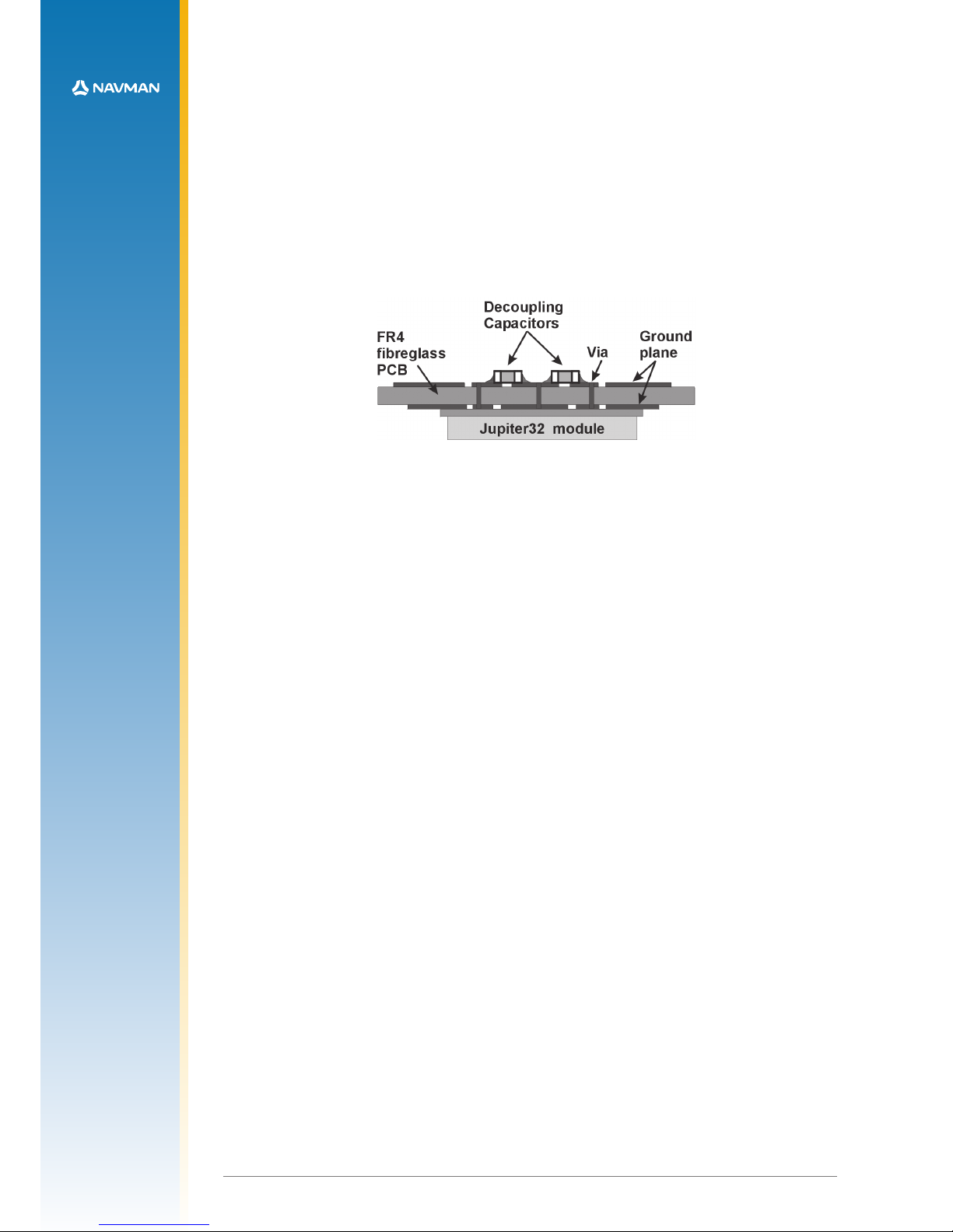
2.2.3 Decoupling
The schematic in Figure 2-2 illustrates a suggested method of decoupling that may be
followed. Table 2-2 suggests decoupling values for all signals relative to the function required.
This level of decoupling may not be required in a particular application, in which case
these capacitors could be omitted. As shown in Figure 2-2, only the signal lines used in the
application require decoupling.
All capacitors are highly recommended if the module will experience substantial
electromagnetic interference (EMI). All low value capacitors should be as close as possible to
the module pad with a short connection to the ground plane (see Figure 2-4). Any data lines
that have not been properly shielded are susceptible to data corruption.
Figure 2-4: Decoupling Capacitor Placement
2.2.4 Serial RS232 data level shifter
To connect the module to a PC COM port, the serial data signals must be level shifted to
RS232 levels. This has not been shown in the reference design, but many single chip RS232
level shifters are available, such as MAX3232.
Note: It is highly recommended to provide test points on the serial data lines and ‘BOOT’
signal (pad C4), even if the application circuit does not use these signals. This will allow the
user to connect to these signals if a rmware upload or new conguration is required. These
test points can take the form of an untted ‘through-hole’ connector. Refer to Figure 2-2.
2.3 PCB design recommendations
The modules are surface mounted devices, hence the layout of the application PCB plays an
integral part in the overall performance of the nished system.
It is not difcult to design such a PCB, despite the presence of high frequency, low level radio
signals. The following recommendations have been offered to allow the designer to create a
design that will meet the requirements of this product.
Figure 2-1 shows the copper pad dimensions and layout.
2.3.1 Choice of PCB stack up
In general, a two layer PCB substrate can be used, with all the RF signals on one side. Multilayer boards can also be used. The design recommendations here only address the microstrip
style of RF connection. Stripline designs can also be accommodated, however, long lengths
of stripline can cause excessive signal loss and vias in the signal track should be avoided.
2.3.2 Ground plane design
A complete ground plane should be used under the PCB with signal tracks on the same
layer as the module. The ground return for any signal should ideally have a clear path back
to its source and should not mix with other signal’s ground return paths. For this reason, RF
signal ground, underneath the microstrip antenna connection, should not be shared with any
digital signal or power supply return paths. Pads A2 and B1 are the RF signal ground return
connections.
Page 9
LA00 0605 D © 2007 Navm an New Zealand. All righ ts reser ved. Proprietary informatio n and specications subject to change without notice.
6
2.3.3 Decoupling components
The recommended values for power and signal decoupling are shown in Table 2-2. The
placement of these components must ensure that the low value capacitors have very short
connections to the module pad and to the ground plane.
Function Pad Decoupling
PWRIN F1 1 µF||10 nF
BOOT C4 27 pF
RXA D5 27 pF
TXA D7 27 pF
TXB F6 27 pF
RXB E6 27 pF
RF_ON A7 27 pF
VANT A4 1 nF
VCC_RF F3 1 µF||1 nF
VBATT F2 10 nF
N_RESET E5 27 pF
N_GPS_FIX D4 27 pF
GPIO (ALL) - 27 pF
WAKEUP F4 27 pF
LNA_EN C5 27pF
1PPS E7 27 pF
Note: ‘||’ represents a parallel connection
Table 2-2: Decoupling recommendations
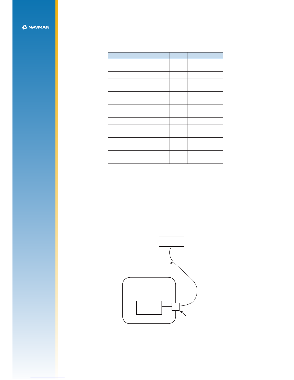
2.3.4 Antenna connection
The PCB layout design of the antenna input connection requires the appropriate selection of
PCB track width, substrate material and careful attention to the layout geometry. If this overall
system is not implemented correctly, the module will receive poor GPS signals and therefore
provide inferior navigation data.
Figure 2-5 shows an example of a PCB design integrating an external active antenna
connected via an MCX or SMA coaxial connector.
Application PCB
Jupiter
module
Active GPS
antenna
connec ting coa x carry ing
GPS signals and DC
power for amplication
coaxi al connec tor
tted to a pplication
PCB
Figure 2-5: Arrangement of active antenna and application board
Page 10

LA00 0605 D © 2007 Navm an New Zealand. All righ ts reser ved. Proprietary informatio n and specications subject to change without notice.
7
The modules can be used with a passive patch antenna if the connection to the antenna
input is very short. It is possible to mount the patch antenna on the same PCB as the module,
but to reduce the possibility of digital noise, it is recommended that the antenna be mounted
on the opposite side of the board to the module. (Figure 2-6 shows an example of a PCB
design integrating a passive patch antenna.)
Figure 2-6: Cross section of application board with passive patch antenna
2.3.5 Design of 50 ohm microstrip antenna connection
When designing the signal track from the antenna connection to the antenna input on the
module, a controlled impedance microstrip with a characteristic impedance of 50 ohms at
1.5 GHz must be used.
The PCB parameters that affect impedance are as follows:
1. Track width (W)
2. PCB substrate thickness (H)
3. PCB substrate permittivity (εr)
4. To a lesser extent, PCB copper thickness (T) and proximity of same layer ground plane.
Figure 2-7 shows a representation of the PCB microstrip and its parameters.
Figure 2-7: PCB microstrip dimensions
Table 2-3 shows typical track widths for an FR4 material PCB substrate (permittivity εr of 4.3
at 1.5 GHz) and different PCB thickness. The effect of track thickness (T) can be ignored for
the short track lengths associated with this design.
Substrate
material
Permittivity
ε
r
Substrate
thickness
H (mm)
Track width
W (mm)
FR4 4.3
1.6 2.0
1.2 1.8
1.0 1.6
0.8 1.4
0.6 1.2
0.4 0.7
0.2 0.4
Table 2-3: PCB substrate thicknesses v track width
Page 11

LA00 0605 D © 2007 Navm an New Zealand. All righ ts reser ved. Proprietary informatio n and specications subject to change without notice.
8
Notes:
1. If a multi-layer PCB is used, the thickness is the distance from signal track to nearest
ground plane.
2. If the antenna connection is routed under the module, the track width should be
approximately halved for that section only.
It is recommended that the antenna connection PCB track should be routed around the
outside of the module outline, kept on a single layer and have no bends greater than
45 degrees. It is not recommended (for production reasons) to route track under the module,
but if track has to route under the module, it should have a modied track width and solder
mask to avoid short circuits to the underside of the module.
To minimise signal loss and reduce the requirement for vias, it is recommended the signal
track not be placed on an inner layer of a multi-layer PCB.
The PCB track connection to the RF antenna input must:
• have a characteristic impedance of 50 ohm
• be as short as possible
• be interfaced to a coaxial connector if an external antenna is used
• have max clearance to ground on the same layer, or at least be half the substrate thickness
• be routed away from noise sources such as: switching power supplies, digital signals,
oscillators and transmitters
The PCB track connection to the RF antenna input must not have:
• vias
• sharp bends
• components overlaying the track
2.4 Antenna system design choices
2.4.1 Antenna types
The role of the antenna is to lter, amplify and down-convert the incoming GPS signals into
an electric signal that can be processed by the receiver electronics within the RF section.
There are several designs of GPS antennas:
Monopole, or dipole, congurations.
Quadrilar helices.
Spiral helices.
Microstrips - active and passive.
Planar rings (“choke ring”), and other multipath-resistant designs.
There are special considerations for GPS antennas. They must be able to pick up and
discriminate very weak signals. GPS signals are circularly polarised, so the GPS antenna
must also be circularly polarised. The antenna gain pattern design is intended to enhance the
ability of the RF section to lter multipath and low elevation signals. An essential requirement
of any consumer GPS product is that the antenna is a stable electrical centre which is
coincident with the geometric centre and insensitive to the rotation and inclination of the
antenna.
The main parts of the construction of the antenna consists of: (a) the omnidirectional antenna
element, (b) the antenna preamplier electronics, and (c) a ground plane (though not always
present). The industry has widely adopted the patch antenna as the most common and
practical design.
There are two major types of GPS antenna patch antennas: passive and active. The active
antenna has a built in LNA (Low Noise Amplier) to increase the strength of the signal, and to
compensate for the signal loss in a long cable connection.
Page 12

LA00 0605 D © 2007 Navm an New Zealand. All righ ts reser ved. Proprietary informatio n and specications subject to change without notice.
9
The features of each type of antenna are shown in Table 2-4, comparing an externally
mounted active antenna with a passive patch antenna mounted on the same PCB as the
module.
Feature Passive antenna Active antenna
antenna requires close proximity to receiver yes no
consumes power no yes
can be mounted remote from receiver no yes
gives good performance in poor signal situations no yes
has built in additional ltering no yes
low cost yes no
requires a coaxial connector no yes
Table 2-4: Passive and active Patch antenna features
2.4.2 Active antenna
An active antenna comprises a passive antenna with a built in LNA that requires a power
supply. Active antennas are used when the antenna input is connected to the receiver
through a coaxial cable (usually longer than 3 m) or any high loss transmission path.
The GPS signals experience loss in the transmission path from the antenna. The loss is
overcome by the antenna’s LNA, which amplies the signal before it enters the transmission
path.
The amplication is also used to enhance the signal in areas of low signal. If the coaxial
cable is shorter than 3 m it may experience too much gain at the receiver and degrade the
performance. There are some variations as to how the antenna will receive its power, but it is
usually supplied through the coaxial cable via the antenna input as shown in Figure 2-5.
Refer to Table 2-5 for the recommended active antenna characteristics.
2.4.3 Passive antenna
A passive antenna does not require any power because it has no amplier. This is not the
best choice if signal strength is a concern, however, it may be sufcient if the signal path is
kept to a minimum (usually below 300 mm). An advantage to using a passive antenna is the
ability to mount directly onto the application. For best performance, a passive patch antenna
should have a metal ground plane (about 80 mm in diameter) placed directly under the
antenna, and it is advisable to shield the module and application circuits from the antenna.
For this reason the antenna and Jupiter 32 module should not be mounted on the same side
of the PCB (see Figure 2-6).
Any cover close to the antenna (called the superstrate) will cause the resonant frequency and
efciency of the antenna to drop. It is therefore recommended to keep any distance to the
superstrate to a minimum of 3 mm from the top surface of the patch.
See Table 2-5 for recommended characteristics of both passive patch and active antennas
for use with the Jupiter receiver.
Page 13

LA00 0605 D © 2007 Navm an New Zealand. All righ ts reser ved. Proprietary informatio n and specications subject to change without notice.
10
Characteristic Active antenna Passive antenna
polarisation
right-hand circular polarised right-hand circular polarised
receive frequency L1
1.57542 GHz
+/- 1.023 MHz
1.57542 GHz
> +/- 1.023 MHz
power supply 3 V (typ), 5 V max. –
DC current < 10mA at 3 VDC –
antenna gain –
+2 to 5 dBi with 1 dB loss (max)
in connections
total gain (includes
antenna gain, LNA
gain and cable loss)
≤ 26 dBi (Jupiter 20)
≤18 dBi (Jupiter 32)
–
axial ratio < 3 dB < 3 dB
output VSWR < 2.5 –
Table 2-5: Recommended antenna characteristics
Note: GPS active and passive antenna selection must include practical TTFF tests
in weak and strong outdoor environments – noting peak and average signal strength
measurements. This must be done in comparison with the antenna supplied in the
Development kit. Performance results and signal strength measurements must be
comparable to the reference antenna supplied. Passive antenna signal strength
measurements will be on average lower than an active antenna. This depends on size of
patch antenna/ground plane, distance from RF input, gain of the element and noise in the
application circuit. However, the TTFF should be comparable in open sky conditions. An
active antenna is recommended if peak performance is required in very weak or obscured
conditions.
2.4.4 Jupiter module used as a GPS sensor
The adapter board reference design shows how a Jupiter 32 GPS receiver module can
be used with an external active antenna via a coax connector (See Figure 2-5). The same
design can be used with a passive patch antenna on the same PCB. The module is placed
so the connection between the antenna and the antenna input pad is as short as possible.
Also note, the PCB should have a complete ground plane on the patch side of the board
which serves as the ground plane required by the antenna (See Figure 2-6).
The serial data from the module must be connected to a local host processor, and care
should be taken so noise from these devices cannot enter the signal path or GPS antenna. It
is recommended that all digital devices are placed on the opposite side of the board from the
antenna.
2.4.5 DC supply protection for an active antenna
Antenna DC supply current limit
When the Jupiter 32 receiver is used with an external active antenna, the DC supply in the
coax cable is vulnerable to over-current if a fault occurs in the antenna. For example, this can
happen if its cable gets crushed in a car door.
Warning: The Jupiter 32 module antenna power feed does not have internal current limiting.
Damage can occur if unlimited current is permitted to ow through the module antenna power
feed components.
The circuit shown in Figure 2-8 (next page) will provide over-current protection.
Page 14
70 mA Antenna supply current limit
R1
10R
C9
100nF
GND
SUPPLY_INPUT
3-5 VDC
200 mW
Q2
BC857B
Q1
BC857B
GND
GND G ND
C8
100nF
C7
18pF
R10
1K
L3
120R @ 100 MHz
ANTEN NA_ SUPPLY
(V_A NT)
LA00 0605 D © 2007 Navm an New Zealand. All righ ts reser ved. Proprietary informatio n and specications subject to change without notice.
11
Figure 2-8: Simple current limiter circuit
NOTE: Ensure that the In-rush current of your active antenna does not cause it to approach the
current limit.
Transistor Q1 serves as a series pass transistor. Q2 is used to sense the current in the
antenna circuit, turning off Q1 if the voltage across the current sense resistor R1 exceeds
0.6 V. This circuit does not turn off the supply to the antenna, but merely limits it to a safe
value. With the components shown the supply will be limited to approximately 70 mA.
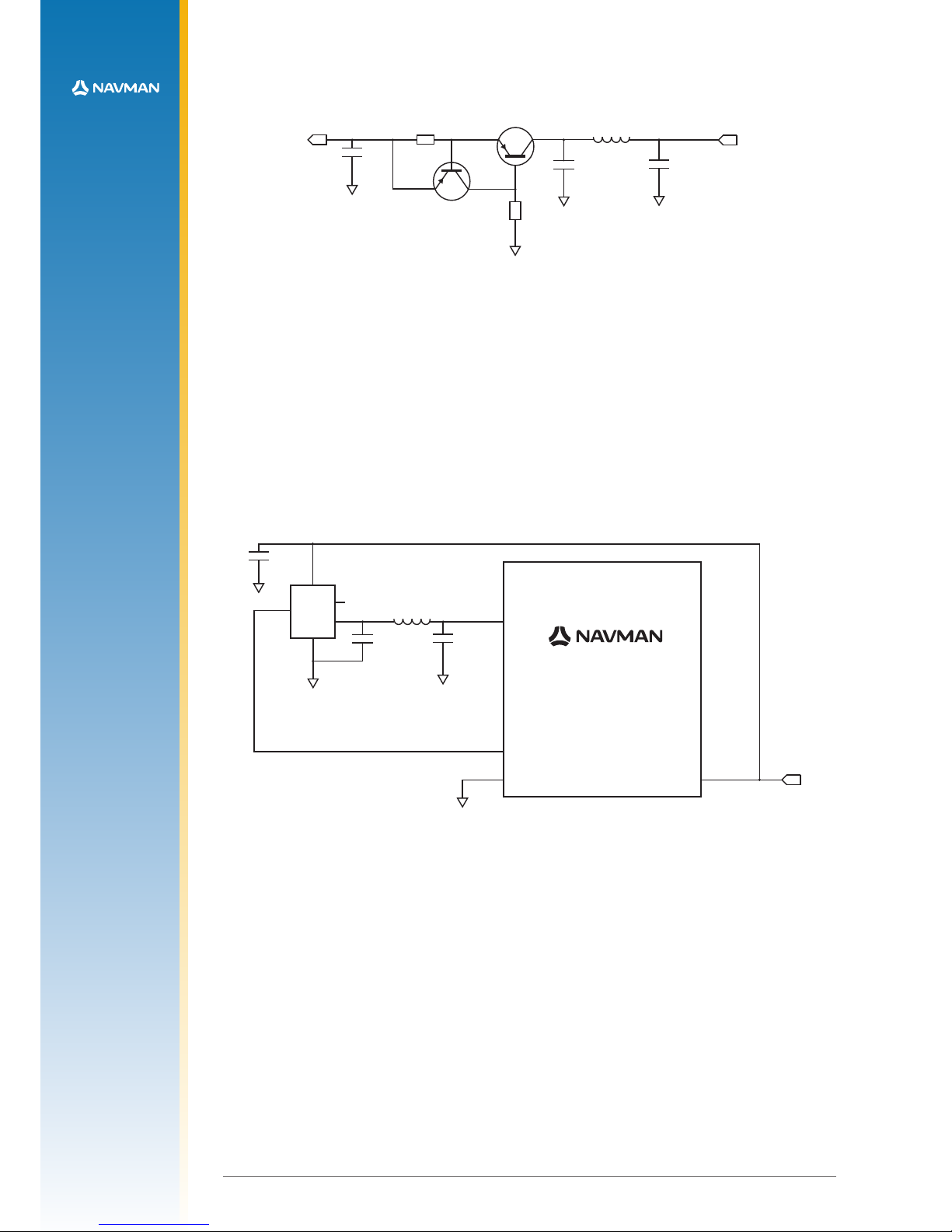
Other options are available to provide this function. MAXIM can supply a current trip IC
that will turn off the load if a preset supply current is exceeded. The part number for this is
MAX4785. The circuit is shown in Figure 2-9.
Figure 2-9: External Active Antenna Control and Current Limit circuit
Electro-resistive fuses can be used to protect the supply over-current. These are available
from Bourns, Vitromon and other manufacturers.
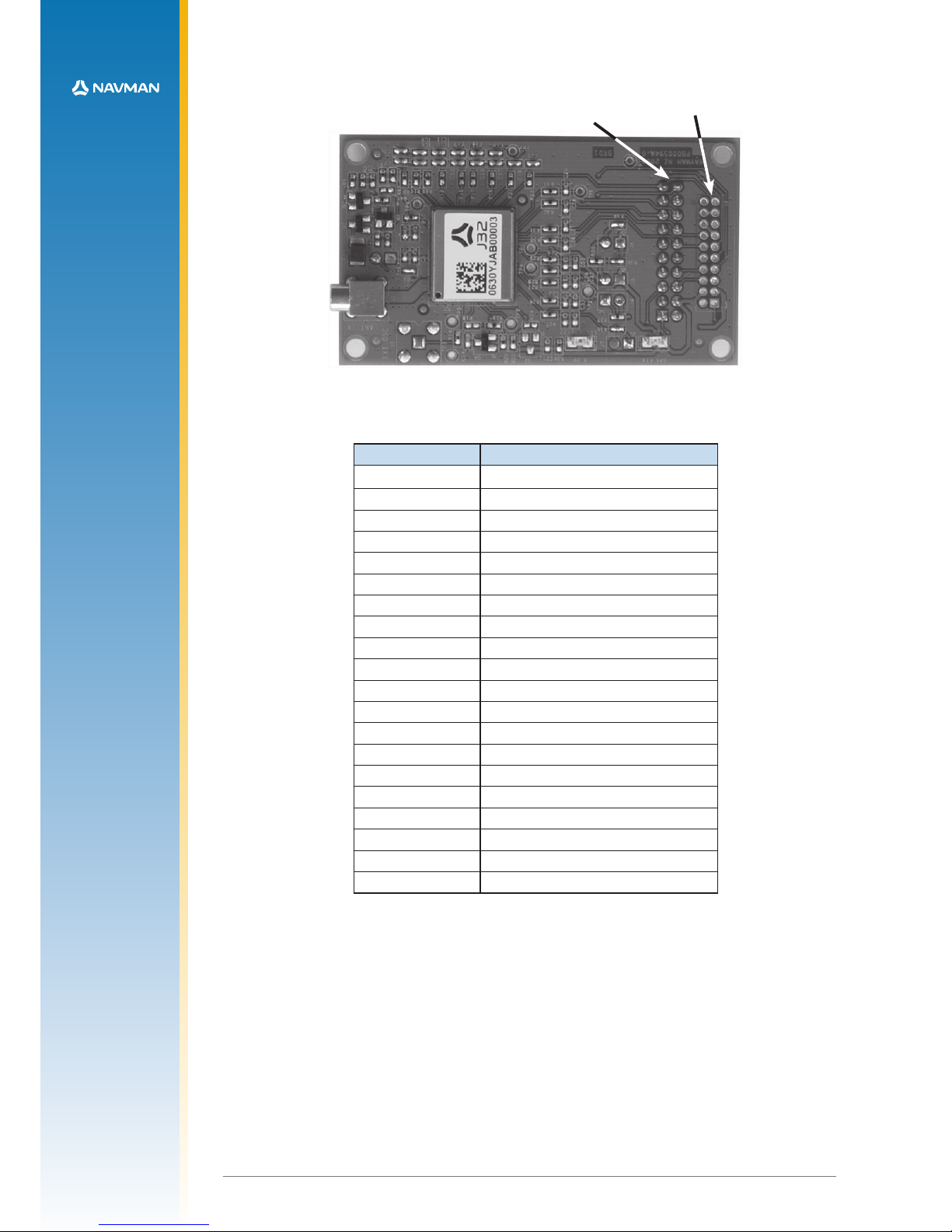
2.5 Jupiter adapter printed circuit board
The Jupiter 32 module supplied in the Development Kit is mounted on a carrier PCB in a method
typical of a customer application. This carrier PCB illustrates and implements many of the design
considerations discussed in this integrator’s manual.
The module is interfaced through a downward-facing 20-pin data connector.
The RTC (Real-Time Clock) backup supply voltage can be provided by an on-board lithium cell,
or from the Development unit backup supply. The adapter board carries a switch debounce IC to
provide reliable reset action from the Development unit.
Figure 2-10 (next page) shows the adapter board with the positions of the connectors and
indicators.
Antenna current limit using an IC
Jupiter G PS Module
A4
C5
GND
C5
100 nF
GND
GND
GND
GND
C4
100 nF
C6
18 pF
L2
120R @100 MHz
OUT
ON
IN
FLAG
3
1
2
4
5
PWR_IN
antenna po wer enable
U3
MAX478 5EXK–T
antenna sh ort circ uit sense si gnal
F1
Jupiter 32
Page 15
LA00 0605 D © 2007 Navm an New Zealand. All righ ts reser ved. Proprietary informatio n and specications subject to change without notice.
12
J2
(on bottom side)
J1
(not loaded)
Figure 2-10: Jupiter 32 adapter board
Refer to Table 2-6 for a description of the connector interfaces.
Jupiter function J2 (2.54 mm pitch header) pin no.
VANT 1
no connection 2
VBATT 3
VDD 4
N_RESET 5
reserved 6
reserved 7
BOOT 8
reserved 9
RF_ON 10
TXA 11
RXA 12
reserved 13
TXB 14
RXB 15
WAKEUP 16
GND 17
reserved 18
1PPS 19
N_GPS_FIX 20
Table 2-6: Connector conguration
Page 16

LA00 0605 D © 2007 Navm an New Zealand. All righ ts reser ved. Proprietary informatio n and specications subject to change without notice.
13
3.0 Packaging and delivery
Jupiter 32 modules are shipped in Tape and Reel form. The reeled modules are shipped with
250 units per reel. Each reel is ‘dry’ packaged and vacuum sealed in an Moisture Barrier Bag
(MBB) with two silica gel packs and placed in a carton.
All packaging is ESD protective lined. The Jupiter 32 GPS receiver is a Moisture Sensitive
Device (MSD) level 3. Please follow the MSD and ESD handling instructions on the labels of the
MBB and exterior carton. See Figures 3-1, 3-2 and 3-3.
CAUTION
This bag contains
MOISTURE SENSITIVE DEVICES
1. Calculated shelf life in sealed bag: 12 months at < 40oC and 90%
relative humidity (RH).
2. Peak package body temperature:
o
C,
If blank see adjacent bar code label
3. After bag is opened, devices that will be subject to reow solder or
other high temperature process must be:
a) mounted within hours, at factory conditions
If blank see adjacent bar code label
≤ 30oC/60% RH, or
b) stored at ≤ 10% RH.
4. Devices require baking before mounting if:
a) humidity indicator card is > 10% when read at 23±5oC,
b) condition 3a or 3b not met.
5. If baking is required, devices may be baked for 48 hours at 125±5oC.
Note: If device containers cannot be subjected to high temperature or
shorter bake times are desired,
reference: IPC/JEDEC J-STD-033 for bake procedure.
Bag seal date
o
C,
If blank see adjacent bar code label
Note: Level and body temperature dened by IPC/JEDEC J-STD-020
Figure 3-1: Moisture Barrier Bag Label
240
48
330.0
100 -0+2
All dimensions in mm
Figure 3-2: Reel dimensions
Page 17

LA00 0605 D © 2007 Navm an New Zealand. All righ ts reser ved. Proprietary informatio n and specications subject to change without notice.
14
Figure 3-3: Jupiter 32 Packaging
44
44mm
20.00
2.00
4.00
2.0
1.5
1.75
20.20
0.35±0.05
3.2±0.10
17.3±0.10
13.30±0.10
250 per reel
All Dim in mm
Direction of Feed
Page 18

LA00 0605 D © 2007 Navm an New Zealand. All righ ts reser ved. Proprietary informatio n and specications subject to change without notice.
15
4.0 Manufacturing process recommendations
The Jupiter 32 uses the latest Land Grid Array (LGA) technology. Solder interconnect is
formed solely by solder paste applied to the board assembly. This results in a low stand-off
height, depending on solder paste volume and Printed Circuit Board (PCB) geometry. This
makes LGA ideal for small form-factor applications. Solder joint reliability studies indicate that
LGA greatly exceed typical industry reliability.
4.1 Solder methods
The Jupiter 32 has 34 surface mount connection pads that have a base metal of copper
with an Electroless Nickel Immersion Gold (ENIG) nish. This is suitable for a lead free
manufacturing process. Critical factors to ensure successful circuit board assembly with LGA
devices include, the design of the solder paste stencil, the solder paste and reow prole
used. Stencil attributes that have been shown to succeed in tests are solder stencil thickness,
aperture diameter, paste release characteristics, and practices to ensure consistent solder
paste volumes that exceed recommended minimums.
4.1.1 Solder paste type
The module will accept all commonly used solder pastes. The solder paste can be lead
based or lead-free. In all processes, factors such as circuit board thickness, fabrication
complexity, assembly process compatibility, and surface nish should be taken into
consideration. Also, due to the low standoff height of LGA devices and difculty cleaning, a
no-clean paste is recommended.
4.1.2 Solder paste mask size
Solder paste mask size should be adjusted by experimentation according to the production
process requirements. As a starting point, a 0.75:1 (paste mask:pad size) ratio is
recommended.
4.1.3 Solder paste stencils
A 0.125 mm (5 mil) thick stencil is recommended with LGA.
4.1.4 Reow prole recommendations
An optimal reow prole depends on solder paste properties and should be optimised and
proven out as part of an overall process development. The following guidelines represent
good soldering practices to help yield high quality assemblies with minimum rework.
It is important to provide a solder reow prole that matches the solder paste supplier’s
recommendations. Some uxes need a long dwell time below the temperature of 180°C,
while others will be burned up in a long dwell. Temperatures out of bounds of the solder paste
ux recommendation could result in poor solderability of components on the board. Solder
paste suppliers can recommend an suitable reow prole to give the best solderability. The
maximum reow temperature is 260 °C for 10 seconds.
The typical reow prole consists of four sections. In the preheat section, the PCB assembly
should be preheated at the maximum rate of 1° to 2° C/sec to start the solvent evaporation
and to avoid thermal shock. The assembly can then be heated for 60 to 120 seconds to
remove solder volatiles and activate the ux so the temperature of the package rises above
100° C. The reow section of the prole, the time above liquidus (approx. 185° C), can be
between 45 to 60 seconds with a peak temperature in the range of 230° to 260° C. This
allows all solder joints on the assembly to fully reow and a maximum peak temperature that
is below the maximum that the devices or solder material can tolerate. Finally, the assembly
can undergo cool-down in the fourth section of the liquidus point (approx. 185° C). The actual
prole parameters depends upon the recommendations of the solder paste supplier and
other reow requirements of the customer’s PCB.
Refer to Figure 4-1 for sample lead and lead-free reow proles.
Page 19

Temperature
o
C
Time Sec
260
3000
Pre-heat
Reow
Cool-down
Liquidus Temp.
Peak Temp.
Pb Solder
Pb-free Solder
Heat
LA00 0605 D © 2007 Navm an New Zealand. All righ ts reser ved. Proprietary informatio n and specications subject to change without notice.
16
Figure 4-1: Sample Lead and Lead free reow prole
4.1.5 Coating
The nal PCB may be selectively coated with an acrylic resin, air / oven cured conformal
coating, clear lacquer or corresponding method, which gives electrical insulation and
sufcient resistance to corrosion.
4.1.6 Post reow washing
It is recommended that a low residue solder paste is used to prevent the need for post reow
washing. If a washing process is used, an aqueous wash is not recommended due to the
long drying time required and danger of contaminating the ne pitch internal components.
4.1.7 Pre-baking
The modules will be delivered on a tape and reel package, and sealed in an airtight bag. The
MSR (Moisture Sensitivity Rating) is 3, therefore they should be loaded and reowed within
168 hours (7 days). If the modules are in ambient humidity for longer than this, a pre-baking/
drying process will be required.
4.1.8 Rework
It is recommended that no more than 2 reow cycles are performed and that the maximum
reow temperature recommended by the solder paste manufacturer is not exceeded. The
maximum ramp-up rate of 3o C/sec for leaded solder or 4o C/sec for lead free solder should
not be exceeded.
Navman recommends that rework and repair is carried out in accordance with the following
guidelines:
• IPC-7711 Rework of Electronic Assemblies
• IPC-7721 Repair and Modication of Printed Boards and Electronic Assemblies
For proper removal of the part, special nozzles should be used for local heating of the part
to avoid reow of adjacent parts. The PCB assembly should be preheated to about 75° C
from the bottom using convective pre-heaters and the preheated nozzle should be lowered
Page 20

LA00 0605 D © 2007 Navm an New Zealand. All righ ts reser ved. Proprietary informatio n and specications subject to change without notice.
17
on the part. The proper nozzle should also heat the component leads by either hot gas or hot
bar. The ideal reow prole should be the same as the one used for mounting the part and
depends upon the paste used. The reow zone can be shortened as long as the reow is
complete. The part should then be lifted off automatically during the transition from reow to
cool down cycles using a vacuum.
4.1.9 Site Redress and Cleaning
Once the part is removed, the site needs to be cleaned for attachment of a new package.
This may be done by vacuum de-soldering or wick. Low-temperature, blade style conductive
tools in conjunction with de-soldering braids can also be used. Once all residual solder is
removed, the site should be cleaned with appropriate solvent such as alcohol and a lint-free
swab.
4.1.10 Application of Solder Paste
For a precise and uniform solder paste deposition on the redressed site, it is recommended
that a miniaturized stencil for the individual component be used. The stencil should be
aligned under 50x to 100x magnication, depending on the part. After precise alignment, the
stencil should be lowered onto the PCB and the paste should be applied in one pass.
4.1.11 Placement and Attachment of the New Component
The new part should be placed on the site using a split-beam alignment where a dual
image of the part leads and the land pattern on the PCB can be viewed on a high-resolution
monitor. Once aligned, the part should be placed on the site and attached to the board using
the reow prole used for the part removal.
5.0 Software application information
5.1 Normal mode operation
In normal mode of operation, the baseband processor software runs continuously, providing
a navigation solution at the maximum rate of once per second. No power saving functions are
applied.
If the power to the module is disrupted, the restart time can be shortened to a warm or hot start
by keeping the RTC and SRAM contents valid with a backup battery on the VBATT input.
If the module has been turned off for longer than 2 hours, the unit will revert to a warm or cold
start. This is caused by the stored ephemeris data becoming invalid after 4 hours.
5.2 Power management
The TricklePower mode of operation can be enabled to reduce the average power consumption.
The main power is supplied to the module continuously. An internal timer wakes the processor
from sleep mode. The module computes a navigation position x, after which the processor
reverts to sleep mode. The duty cycle is controlled by a user-congurable parameter.
If ephemeris data becomes outdated, the TricklePower mode will attempt to refresh the data set
within every 30 minute period, or for every new satellite that comes into view.
With TricklePower set to a 20% duty cycle, a power saving of 50% can easily be achieved with
minimal degradation in navigation performance.
5.2.1 Adaptive TricklePower mode
In Adaptive TricklePower mode, the processor automatically returns to full power when signal
levels are below the level at which they can be tracked in TricklePower mode. This is the
default behaviour when TricklePower is active. Adaptive TricklePower is always enabled on
the Jupiter 32.
Page 21

LA00 0605 D © 2007 Navm an New Zealand. All righ ts reser ved. Proprietary informatio n and specications subject to change without notice.
18
5.2.2 Push-to-Fix mode
Unlike TricklePower, the operation in this mode is not cyclic. This mode always forces the
GPS software to revert to a continuous sleep mode after a navigation position x. It will stay
in sleep mode until woken by wakeup input, and compute a fresh position.
If the ephemeris data become invalid or new satellites come into view, the RTC has the ability
to self activate and refresh the data, thus keeping the restart TTFF very short.
This mode yields the lowest power consumption of the module, and is ideal where a battery
powered application requires very few position xes.
For further information on the TricklePower and Push-To-Fix modes refer to the Low Power
Operating Modes application note (LA000513).
5.3 Serial I/O
The module can output serial data in the NMEA format or SiRF Binary format. The serial I/O
protocols are dened in the Navman NMEA reference manual (MN000315) and the SiRF Binary
Protocol reference manual. These describe the format of the serial data from the module, as well
as the structure of the commands. Navman has provided additional functionality to the NMEA
protocol as detailed in the following sections.
5.3.1 Default settings
The default protocol is NMEA, at a baud rate of 9600bps. The frame format is 8 data bits, no
parity bit and 1 stop bit.
The following messages are output by default, at a rate of once per second each:
$GPGGA, $GPGLL, $GPGSA, $GPGSV, $GPRMC, $GPVTG, $GPZDA
All output messages have checksums by default.
5.3.2 NMEA input commands
All NMEA input commands are in the form:
$PSRFxxx,…[*CS]<cr><lf>
where xxx is a decimal number between 100 and 255 (inclusive).
Note: In each case, CS represents an NMEA checksum. This checksum is detailed in the
Navman NMEA reference manual MN000315.
Acknowledgements
All input commands other than the standard SiRF commands will be acknowledged with a
sentence of the form:
$PTTK,…*CS
Where the arguments provided to a command are invalid, the response will be the message:
$PTTK,NACK*CS
Checksums
All input commands are accepted whether or not they include a checksum, however if a
checksum is included it must be correct in order for the message to be accepted.
Incorrect checksums will result in the response:
$PTTK,CHECKSUM*CS
Unused messages
Input messages where the message ID is not between 100 and 255, or where the message
ID does not correspond to a specied function, result in the response:
$PTTK,INVALID*CS
Page 22

LA00 0605 D © 2007 Navm an New Zealand. All righ ts reser ved. Proprietary informatio n and specications subject to change without notice.
19
Errors
Errors in message receipt (other than checksum errors) result in the response:
$PTTK,ERROR,xx*CS
where xx is a hexadecimal error code.
Magnetic Variation (Declination)
The Jupiter 32 module does not calculate the magnetic variation.
5.4 Navman proprietary NMEA low power mode messages
Navman has added a number of proprietary NMEA input messages to congure the
TricklePower and Push-To-Fix modes.
5.4.1 Low power conguration
The following message sets the receiver to low power mode:
$PSRF151,a,bbbb,cccc[*CS]<cr><lf>
where:
Field Description
a Push-To-Fix (1=on, 0=off)
b
TricklePower duty cycle (parts per
thousand)
c TricklePower on time (milliseconds)
*Note that Push-To-Fix does not require elds b and c so
they may be left blank
Table 5-1: Low power modes message values
This message is the NMEA equivalent of the SiRF Binary input message ID 151.
System response:
$PTTK,LPSET,a,bbbb,cccc*CS
The updated values returned by the system are as described in Table 3-1.
5.4.2 Low power acquisition conguration
The following message sets the acquisition parameters of the low power mode:
$PSRF167,aaaaaa,bbbbbb,cccc,d[*CS]<cr><lf>
where:
Field Description
a maximum off time (milliseconds)
b maximum search time (milliseconds)
c Push-To-Fix period (seconds)
d adaptive TricklePower (1=on, 0=off)
Table 5-2: Low power acquisition input values
This message is the NMEA equivalent of the SiRF Binary input message ID 167.
System response:
$PTTK,LPACQ,aaaaaa,bbbbbb,cccc,d*CS
The updated values returned by the system are as described in Table 3-2.
Page 23

LA00 0605 D © 2007 Navm an New Zealand. All righ ts reser ved. Proprietary informatio n and specications subject to change without notice.
20
5.5 Save and Retrieve Conguration Data to Flash
The current settings of the Jupiter 32 will be stored in Flash memory upon a command from the
user. Refer to Application Note LA000266. All parameters are written as a set.
The following parameters can be stored and retrieved:
· Port A and B protocols
· Port A and B baud rates and frame formats
· NMEA per-message output rates and checksums
· SiRF Binary debug and raw tracker data output
· Datum
· Altitude hold mode, source and default
· Degraded mode and timeout
· DR timeout
· DOP mode and GDOP/PDOP/HDOP thresholds
· Elevation navigation mask
· Power navigation mask
· Static navigation mode
· Track smoothing mode
· TricklePowerTM mode, on time and interval
· Push-to-Fix mode, period, maximum off and acquisition times
· DGPS source
· SBAS default PRN
5.5.1 Writing to Flash
The module accepts NMEA messaging or SiRF Binary messaging. The protocols are
dened in the Navman NMEA Reference Manual (MN000315) and the SiRF Binary Protocol
Reference Manual. These documents describe the structure of the general commands.
NMEA Store to Flash Memory command
To store all relevant parameters to Flash, send the following NMEA sentence:
$PSRF198[*CS] <cr><lf>
SiRF Binary Store to Flash Memory command
To store all relevant parameters to Flash send a SiRF Binary message with Message ID 198.
A payload of this message should have a length of 1 byte.
5.5.2 Retrieving from Flash
At power-up, the unit will retrieve any conguration parameters stored in Flash and restore
them as a set. Individual parameters can not be restored. Settings stored in battery backed
memory are not over written.
To prevent parameters from being restored, drive the defaults pin GPIO Pad A5 to a logic
low.
Logic State Power-up Action
high or oating retrieves stored parameters in Flash on power-up if no data in
battery backup RAM
low (grounded) ignores parameters stored in ash
Table 5-3: Actions based on signal state
5.5.3 Reverting to default settings
To restore the default settings, including deleting all parameters stored in Flash, send a
factory reset command in either the NMEA or SiRF Binary protocols.
Page 24

LA00 0605 D © 2007 Navm an New Zealand. All righ ts reser ved. Proprietary informatio n and specications subject to change without notice.
21
5.6 Selectable User Proles
The purpose of this feature is to provide some typical application proles which users can
select through a simple NMEA message. These proles are macro-like commands that modify
parameters used for common applications. These proles produce optimal navigation default
settings which conform specically to an application’s requirements. They can be then be saved
using the Write-to-Flash feature. The new prole will not be written to Flash automatically.
Available Proles include:
Default - A general prole that balances the needs of most applications.
Automotive - Takes into consideration higher velocities with occasional stopping.
Pedestrian - Takes into consideration slower velocities.
TricklePower - Power saving mode for battery applications. See Low Power Operating
Modes Application Note LA000513
Push to Fix - Only performs a x when requested. For use in special applications. See Low
Power Operating Modes Application Note LA000513
Command
The proles will be selected by an NMEA command
$PSRF197,n<cr><lf>
where n is the prole number:
1. Automotive
2. Pedestrian
3. TricklePower
4. Push to Fix
Refer to Application Note LA000266.
5.7 GPS x output
The GPS x output is an active low output on pin 23 of the module. Whenever the unit has either
a 2D or a 3D x, this output will be low. When the unit has no x, the output will be high.
5.8 Custom application software
The module provides custom modication of the rmware to use available CPU processing
capacities and I/O capabilities. The custom application software can be invoked internally or
externally, providing the ability to dedicate the module as the host application or an external
processor as the host. The module also provides the ability to communicate externally with
standard or customer specic communication protocols.
The custom application software has access to the ash memory, navigation data from the GPS
Navigation software, and access to various I/O lines used on the module.
This can be developed using the SiRF SDK. The SDK provides all the tools and resources
necessary for custom software development. Refer to http://www.sirf.com for more information
about the SDK.
Page 25

LA00 0605 D © 2007 Navm an New Zealand. All righ ts reser ved. Proprietary informatio n and specications subject to change without notice.
22
6.0 Glossary and acronyms
Axial ratio: For an electromagnetic wave having elliptical polarisation, the ratio of the
magnitudes of the major axis and the minor axis of the ellipse described by the electric eld
vector.
EMI: Electromagnetic Interference
ENIG: Electroless Nickel Immersion Gold
FR4 substrate: Flame Retardant type 4
The usual base material from which plated-through-hole and multi-layer printed circuit boards
are constructed. The type ‘4’ indicates woven glass reinforced epoxy resin.
GPS: Global Positioning System
A space-based radio positioning system that provides accurate position, velocity, and time data.
LGA: Land Grid Array
A physical interface for microprocessors. There are no pins on the chip; in place of the pins are
pads of bare gold-plated copper that touch pins on the motherboard.
LNA: Low Noise Amplier
A special type of amplier used to amplify weak signals captured by an antenna.
MCX: A type of miniature coaxial RF connector
NMEA: National Marine Electronics Association
PCB: Printed Circuit Board
RF: Radio Frequency
SDK: Software Development Kit
SMA: SubMiniature version A connectors are coaxial RF connectors developed in the 1960’s
as a minimal connector interface for coaxial cable with a screw type coupling mechanism. The
connector has a 50 Ω impedance.
SRAM: Static Random Access Memory
SMT: Surface mount technology (SMT) is a method for constructing electronic circuits in which
the components are mounted directly onto the surface of printed circuit boards
TTFF: Time-To-First-Fix
The actual time required by a GPS receiver to achieve a position solution. This specication
will vary with the operating state of the receiver, the length of time since the last position x, the
location of the last position x, and the specic receiver design.
Page 26

LA00 0605 D © 2007 Navm an New Zealand. All righ ts reser ved. Proprietary informatio n and specications subject to change without notice.
23
Push-To-Fix and TricklePower are registered trademarks of SiRF Technologies.
© 2007 Navman New Zealand. All Rights Reserved.
Information in this document is provided in connection with Navman New Zealand (‘Navman’) products. These materials
are provided by Navman as a service to its customers and may be used for informational purposes only. Navman
assumes no responsibility for errors or omissions in these materials. Navman may make changes to specications and
product descriptions at any time, without notice. Navman makes no commitment to update the information and shall
have no responsibility whatsoever for conicts or incompatibilities arising from future changes to its specications and
product descriptions. No license, express or implied, by estoppel or otherwise, to any intellectual property rights is
granted by this document. Except as provided in Navman’s Terms and Conditions of Sale for such products, Navman
assumes no liability whatsoever.
THESE MATERIALS ARE PROVIDED ‘AS IS’ WITHOUT WARRANTY OF ANY KIND, EITHER EXPRESSED OR
IMPLIED, RELATING TO SALE AND/OR USE OF NAVMAN PRODUCTS INCLUDING LIABILITY OR WARRANTIES
RELATING TO FITNESS FOR A PARTICULAR PURPOSE, CONSEQUENTIAL OR INCIDENTAL DAMAGES,
MERCHANTABILITY, OR INFRINGEMENT OF ANY PATENT, COPYRIGHT OR OTHER INTELLECTUAL PROPERTY
RIGHT. NAVMAN FURTHER DOES NOT WARRANT THE ACCURACY OR COMPLETENESS OF THE INFORMATION,
TEXT, GRAPHICS OR OTHER ITEMS CONTAINED WITHIN THESE MATERIALS. NAVMAN SHALL NOT BE
LIABLE FOR ANY SPECIAL, INDIRECT, INCIDENTAL, OR CONSEQUENTIAL DAMAGES, INCLUDING WITHOUT
LIMITATION, LOST REVENUES OR LOST PROFITS, WHICH MAY RESULT FROM THE USE OF THESE MATERIALS.
Navman products are not intended for use in medical, lifesaving or life sustaining applications. Navman customers using
or selling Navman products for use in such applications do so at their own risk and agree to fully indemnify Navman
for any damages resulting from such improper use or sale. Product names or services listed in this publication are for
identication purposes only, and may be trademarks of third parties. Third-party brands and names are the property of
their respective owners. Additional information, posted at www.navman.com, is incorporated by reference.
Reader response:
Navman strives to produce quality documentation and welcomes your feedback. Please send comments and
suggestions to tech.pubs@navman.com. For technical questions, contact your local Navman sales ofce or eld
applications engineer.
 Loading...