

Page 1
Manual
Page 2

The information in this document is subject to change without notice and does not represent a
commitment on the part of Native Instruments GmbH. The software described by this document is subject to a License Agreement and may not be copied to other media. No part of this
publication may be copied, reproduced or otherwise transmitted or recorded, for any purpose,
without prior written permission by Native Instruments GmbH, hereinafter referred to as Native
Instruments.
“Native Instruments”, “NI” and associated logos are (registered) trademarks of Native Instruments GmbH.
Mac, Mac OS, GarageBand, Logic, iTunes and iPod are registered trademarks of Apple Inc.,
registered in the U.S. and other countries.
Windows, Windows Vista and DirectSound are registered trademarks of Microsoft Corporation
in the United States and/or other countries.
All other trade marks are the property of their respective owners and use of them does not imply any affiliation with or endorsement by them.
Document authored by: Native Instruments GmbH
Software version: 1.8.0 (04/2015)
Disclaimer
Special thanks to the Beta Test Team, who were invaluable not just in tracking down bugs, but
in making this a better product.
Page 3

NATIVE INSTRUMENTS GmbH
Schlesische Str. 29-30
D-10997 Berlin
Germany
www.native-instruments.de
NATIVE INSTRUMENTS North America, Inc.
6725 Sunset Boulevard
5th Floor
Los Angeles, CA 90028
USA
www.native-instruments.com
NATIVE INSTRUMENTS K.K.
YO Building 3F
Jingumae 6-7-15, Shibuya-ku,
Tokyo 150-0001
Japan
www.native-instruments.co.jp
Contact
NATIVE INSTRUMENTS UK Limited
18 Phipp Street
London EC2A 4NU
UK
www.native-instruments.com
© NATIVE INSTRUMENTS GmbH, 2015. All rights reserved.
Page 4

Table of Contents
Table of Contents
1 Welcome to the Controller Editor! ...............................................................................
1.1 About This Manual ......................................................................................................................13
1.2 Document Conventions ............................................................................................................... 14
2 Installation ...............................................................................................................
2.1 Controller Editor as Part of an NI Product Installation ................................................................ 16
2.2 Downloading the Controller Editor from the Native Instruments Website .................................... 16
3 Quick Start ................................................................................................................
3.1 Switching your NI Controller to MIDI Mode .................................................................................. 19
3.2 Loading MIDI Assignments ......................................................................................................... 21
3.3 Modifying an Assignment ........................................................................................................... 29
3.4 Organizing Your Assignments ..................................................................................................... 31
3.5 Saving and Loading Templates .................................................................................................. 33
3.2.1 Select the NI Controller .............................................................................................. 21
3.2.2 Select a Template ...................................................................................................... 23
3.2.3 Select a Page ............................................................................................................. 24
3.2.4 Select a Pad Page (MASCHINE Controller Family Only) .............................................. 27
3.2.5 Ready to Go? .............................................................................................................. 29
3.4.1 Displaying the Lists of Templates and Pages ............................................................ 31
3.4.2 Renaming Templates and Pages ............................................................................... 32
3.4.3 Re-ordering Templates and Pages ............................................................................. 33
4 Basic Concepts .........................................................................................................
4.1 How the Controller Editor Works .................................................................................................. 36
4.2 Overview of the User Interface .................................................................................................... 36
4.2.1 Application Menu Bar ................................................................................................ 38
4.2.2 Application Control Bar ............................................................................................. 38
4.2.3 Hardware Area ........................................................................................................... 38
13
16
18
36
CONTROLLER EDITOR - Manual - 4
Page 5

Table of Contents
4.3 The Mapping System .................................................................................................................. 47
4.4 To Sum Up… ..............................................................................................................................51
4.2.4 Inspector ................................................................................................................... 40
4.3.1 Assignments .............................................................................................................. 47
4.3.2 Pages (or Knob Pages) ............................................................................................... 47
4.3.3 Pad Pages (MASCHINE Controller Family Only) .......................................................... 48
4.3.4 I/O and Level Pages (MASCHINE STUDIO Only) ........................................................... 48
4.3.5 Jog Wheel Pages (MASCHINE STUDIO Only) ................................................................ 49
4.3.6 Templates .................................................................................................................. 49
4.3.7 Configuration ............................................................................................................ 51
5 Using Your MASCHINE Controller ...............................................................................
5.1 Basic Controls ............................................................................................................................ 52
5.2 Assignable Control Elements ...................................................................................................... 54
5.3 Visual Feedback on Your Controller ............................................................................................ 57
5.4 The Displays ............................................................................................................................... 59
5.3.1 Buttons ...................................................................................................................... 57
5.3.2 Pads .......................................................................................................................... 58
5.3.3 Knobs ........................................................................................................................ 59
5.4.1 Switching Between Display Modes ............................................................................. 59
5.4.2 Knobs Display Mode ................................................................................................... 60
5.4.3 Pad Pages Display Mode ............................................................................................ 61
5.4.4 Knob Pages Display Mode .......................................................................................... 62
5.4.5 Template Display Mode .............................................................................................. 63
5.4.6 Monitor Display Mode ................................................................................................ 63
5.4.7 Settings Display Mode ............................................................................................... 64
6 Using Your MASCHINE MK2 Controller .......................................................................
6.1 Basic Controls ............................................................................................................................ 66
6.2 Assignable Control Elements ...................................................................................................... 68
52
66
CONTROLLER EDITOR - Manual - 5
Page 6

6.3 Visual Feedback on Your Controller ............................................................................................ 71
6.4 The Displays ............................................................................................................................... 74
6.3.1 Buttons ...................................................................................................................... 72
6.3.2 Multicolor Pads .......................................................................................................... 73
6.3.3 Knobs ........................................................................................................................ 74
6.3.4 Control Encoder ......................................................................................................... 74
6.4.1 Switching Between Display Modes ............................................................................. 74
6.4.2 Knobs Display Mode ................................................................................................... 75
6.4.3 Pad Pages Display Mode ............................................................................................ 76
6.4.4 Template Display Mode .............................................................................................. 77
6.4.5 Monitor Display Mode ................................................................................................ 78
6.4.6 Settings Display Mode ............................................................................................... 78
7 Using Your MASCHINE MIKRO Controller ....................................................................
7.1 Basic Controls ............................................................................................................................ 80
7.2 Assignable Control Elements ...................................................................................................... 82
7.3 Visual Feedback on Your Controller ............................................................................................ 84
7.4 The Display ................................................................................................................................. 86
7.3.1 Buttons ...................................................................................................................... 85
7.3.2 Pads .......................................................................................................................... 85
7.3.3 Control Encoder ......................................................................................................... 86
7.4.1 Switching Between Display Modes ............................................................................. 86
7.4.2 Control Display Mode ................................................................................................. 87
7.4.3 Template Display Mode .............................................................................................. 88
7.4.4 Setup Display Mode ................................................................................................... 89
8 Using Your MASCHINE MIKRO MK2 Controller .............................................................
8.1 Basic Controls ............................................................................................................................ 90
8.2 Assignable Control Elements ...................................................................................................... 92
8.3 Visual Feedback on Your Controller ............................................................................................ 94
Table of Contents
80
90
CONTROLLER EDITOR - Manual - 6
Page 7

Table of Contents
8.4 The Display ................................................................................................................................. 97
8.3.1 Buttons ...................................................................................................................... 94
8.3.2 Multicolor Pads .......................................................................................................... 96
8.3.3 Control Encoder ......................................................................................................... 97
8.4.1 Switching Between Display Modes ............................................................................. 97
8.4.2 Control Display Mode ................................................................................................. 98
8.4.3 Template Display Mode .............................................................................................. 98
8.4.4 Setup Display Mode ................................................................................................... 99
9 Using Your MASCHINE STUDIO Controller ...................................................................
9.1 Basic Controls ............................................................................................................................ 101
9.2 Assignable Control Elements ...................................................................................................... 103
9.3 Visual Feedback on Your Controller ............................................................................................ 108
9.4 The Displays ............................................................................................................................... 111
9.3.1 Buttons ...................................................................................................................... 109
9.3.2 Multicolor Pads .......................................................................................................... 110
9.3.3 Knobs ........................................................................................................................ 111
9.3.4 Control Encoder ......................................................................................................... 111
9.4.1 Switching Between Display Modes ............................................................................. 112
9.4.2 Settings Display Mode ............................................................................................... 112
9.4.3 Calibration Display Mode ........................................................................................... 114
9.4.4 Knobs Display Mode ................................................................................................... 115
9.4.5 Pages Display Mode ................................................................................................... 117
9.4.6 Templates Display Mode ............................................................................................ 118
9.4.7 Monitor Display Mode ................................................................................................ 119
10 Using Your TRAKTOR KONTROL X1 ..............................................................................
10.1 Basic Controls ............................................................................................................................ 120
10.2 Assignable Control Elements ...................................................................................................... 121
10.3 Visual Feedback on Your Controller ............................................................................................ 123
101
120
CONTROLLER EDITOR - Manual - 7
Page 8

10.4 Using Two or More TRAKTOR KONTROL X1 Units ......................................................................... 124
11 Using Your TRAKTOR KONTROL X1 MK2 ......................................................................
11.1 Basic Controls ............................................................................................................................ 125
11.2 Assignable Control Elements ...................................................................................................... 126
11.3 Visual Feedback on Your Controller ............................................................................................ 128
11.4 Using Two or More TRAKTOR KONTROL X1 MK2 Units .................................................................. 130
12 Using Your TRAKTOR KONTROL F1 ..............................................................................
12.1 Basic Controls ............................................................................................................................ 131
12.2 Assignable Control Elements ...................................................................................................... 132
12.3 Visual Feedback on Your Controller ............................................................................................ 134
12.4 Using Two or More TRAKTOR KONTROL F1 Units .......................................................................... 137
12.3.1 Buttons and Pads ...................................................................................................... 135
12.3.2 7-segment Display .................................................................................................... 136
13 Using Your TRAKTOR KONTROL Z1 ..............................................................................
13.1 Basic Controls ............................................................................................................................ 138
13.2 Assignable Control Elements ...................................................................................................... 139
13.3 Visual Feedback on Your Controller ............................................................................................ 140
14 Using Your TRAKTOR KONTROL Z2 ..............................................................................
14.1 Basic Controls ............................................................................................................................ 143
14.2 Assignable Control Elements ...................................................................................................... 144
14.3 Visual Feedback on Your Controller ............................................................................................ 146
15 Using Your TRAKTOR KONTROL D2 ..............................................................................
15.1 Basic Controls ............................................................................................................................ 149
15.2 Assignable Control Elements ...................................................................................................... 151
15.3 Visual Feedback on Your Controller ............................................................................................ 154
15.4 The Display ................................................................................................................................. 156
15.3.1 Buttons and Pads ...................................................................................................... 154
15.3.2 Performance Knobs, Slot Volume Faders, and Loop Encoder ...................................... 156
Table of Contents
125
131
138
143
149
CONTROLLER EDITOR - Manual - 8
Page 9

Table of Contents
15.4.1 Control Display Mode ................................................................................................. 157
15.4.2 Adjust Color And Brightness ...................................................................................... 158
16 Using Your TRAKTOR KONTROL S8 ..............................................................................
16.1 Basic Controls ............................................................................................................................ 161
16.2 Assignable Control Elements ...................................................................................................... 163
16.3 Visual Feedback on Your Controller ............................................................................................ 169
16.4 The Displays ............................................................................................................................... 172
16.2.1 Control Elements on the Deck Units ........................................................................... 164
16.2.2 Control Elements on the Mixer ................................................................................... 167
16.3.1 Buttons and Pads ...................................................................................................... 169
16.3.2 Performance Knobs, Slot Volume Faders, and Loop Encoder ...................................... 171
16.4.1 Control Display Mode ................................................................................................. 172
16.4.2 Adjust Color And Brightness ...................................................................................... 174
17 Using Your TRAKTOR KONTROL S4 ..............................................................................
17.1 Basic Controls ............................................................................................................................ 177
17.2 Assignable Control Elements ...................................................................................................... 179
17.3 Visual Feedback on Your Controller ............................................................................................ 183
17.2.1 Control Elements on the Left Deck ............................................................................. 180
17.2.2 Control Elements on the Right Deck .......................................................................... 181
17.2.3 Control Elements on the Mixer ................................................................................... 181
17.2.4 Assignment Parameters ............................................................................................ 183
17.3.1 Buttons ...................................................................................................................... 184
17.3.2 LED Chains ................................................................................................................ 185
18 Using Your TRAKTOR KONTROL S4 MK2 ......................................................................
18.1 Basic Controls ............................................................................................................................ 186
18.2 Assignable Control Elements ...................................................................................................... 188
18.2.1 Control Elements on the Left Deck ............................................................................. 189
18.2.2 Control Elements on the Right Deck .......................................................................... 190
161
177
186
CONTROLLER EDITOR - Manual - 9
Page 10

Table of Contents
18.3 Visual Feedback on Your Controller ............................................................................................ 192
18.2.3 Control Elements on the Mixer ................................................................................... 190
18.2.4 Assignment Parameters ............................................................................................ 192
18.3.1 Buttons ...................................................................................................................... 193
18.3.2 LED Chains ................................................................................................................ 194
19 Using Your TRAKTOR KONTROL S2 ..............................................................................
19.1 Basic Controls ............................................................................................................................ 195
19.2 Assignable Control Elements ...................................................................................................... 196
19.3 Visual Feedback on Your Controller ............................................................................................ 197
19.3.1 Buttons ...................................................................................................................... 198
19.3.2 LED Chains ................................................................................................................ 199
20 Using Your TRAKTOR KONTROL S2 MK2 ......................................................................
20.1 Basic Controls ............................................................................................................................ 200
20.2 Assignable Control Elements ...................................................................................................... 201
20.3 Visual Feedback on Your Controller ............................................................................................ 202
20.3.1 Buttons ...................................................................................................................... 203
20.3.2 LED Chains ................................................................................................................ 204
21 Using Your KOMPLETE KONTROL S-SERIES Keyboard ...................................................
21.1 Basic Controls ............................................................................................................................ 205
21.2 Assignable Control Elements ...................................................................................................... 207
21.3 Defining Key Zones ..................................................................................................................... 210
21.4 Visual Feedback on Your Keyboard ............................................................................................. 215
21.3.1 Overview of the Keybed Area ...................................................................................... 210
21.3.2 Editing Key Zones ...................................................................................................... 212
21.4.1 Visual Feedback on the Displays ............................................................................... 215
21.4.2 Visual Feedback on the Light Guide ........................................................................... 216
21.4.3 Visual Feedback on the Touch Strips ......................................................................... 216
21.4.4 Visual Feedback on the Buttons ................................................................................ 217
195
200
205
CONTROLLER EDITOR - Manual - 10
Page 11

21.5 Using Two or More KOMPLETE KONTROL S-SERIES Units ............................................................ 218
21.6 Stand-alone Operation ............................................................................................................... 218
22 Using Two or More Units of the Same Type .................................................................
22.1 Renaming the Units ....................................................................................................................222
22.2 Accessing Templates and Pages of a Particular Unit ................................................................. 224
22.3 Resolving Device Conflicts ......................................................................................................... 225
23 Reference .................................................................................................................
23.1 The Application Menu Bar ...........................................................................................................227
23.2 The Preferences Window ............................................................................................................. 229
23.3 The Application Control Bar ........................................................................................................ 241
23.4 The Hardware Area ..................................................................................................................... 245
23.5 The Inspector .............................................................................................................................. 249
23.6 MIDI Message Parameters .......................................................................................................... 270
23.1.1 File Menu ................................................................................................................... 227
23.1.2 View Menu ................................................................................................................. 228
23.1.3 Help Menu ................................................................................................................. 228
23.2.1 General Page ............................................................................................................. 230
23.2.2 Controller Page .......................................................................................................... 231
23.3.1 Device Menu .............................................................................................................. 242
23.3.2 Connect Button .......................................................................................................... 243
23.3.3 MIDI Activity Indicator ............................................................................................... 244
23.3.4 NI Logo ...................................................................................................................... 244
23.4.1 Label Fields ............................................................................................................... 245
23.4.2 Selection Frame ......................................................................................................... 247
23.4.3 Page Areas and Page Menus ..................................................................................... 247
23.5.1 Templates Pane ......................................................................................................... 250
23.5.2 Pages Pane ................................................................................................................ 256
23.5.3 Assign Pane ............................................................................................................... 266
Table of Contents
222
227
CONTROLLER EDITOR - Manual - 11
Page 12

Table of Contents
23.6.1 MIDI Message Types – Type Menu .............................................................................. 270
23.6.2 Assignments for Buttons ........................................................................................... 274
23.6.3 Assignments for Key Zones ........................................................................................ 280
23.6.4 Assignments for the Pads – Hit Action ...................................................................... 281
23.6.5 Assignments for Knobs and the Like .......................................................................... 282
23.6.6 Assignments for the Pads – Press Action .................................................................. 283
23.6.7 Assignments for Digital Encoders .............................................................................. 284
23.6.8 Assignments for Analog Encoders ............................................................................. 286
23.6.9 Assignments for Touch Strips – Position Action (TRAKTOR KONTROL Devices) .......... 289
23.6.10 Assignments for Touch Strips (KOMPLETE KONTROL S-SERIES) ................................. 290
23.6.11 Assignments for LED Chains and 7-segment Displays .............................................. 293
CONTROLLER EDITOR - Manual - 12
Page 13

Welcome to the Controller Editor!
About This Manual
1 Welcome to the Controller Editor!
This powerful tool turns your Native Instruments hardware controller into a versatile and efficient MIDI remote control for your studio and live setup.
With the Controller Editor, you can precisely define which MIDI message to send when using
your NI controller. This way, you can put your whole music setup right at your fingertips and
remotely control MIDI-capable software or hardware from your NI controller. After you have
prepared your MIDI assignments with the Controller Editor, you can focus on what it’s all
about: making music!
1.1 About This Manual
This manual is divided into four parts:
• The first part introduces you to the Controller Editor: after a short description of the installation procedure (chapter ↑2, Installation), we will start with a brief tutorial (chapter
↑3, Quick Start).
• The second part illustrates the user interface of the Controller Editor, mapping scheme
and the various ways to interact with the software (chapter ↑4, Basic Concepts). This will
familiarize you with Controller Editor’s workflow.
• The third part shows you how to use your particular NI controller(s):
◦ chapter ↑5, Using Your MASCHINE Controller,
◦ chapter ↑6, Using Your MASCHINE MK2 Controller,
◦ chapter ↑7, Using Your MASCHINE MIKRO Controller,
◦ chapter ↑8, Using Your MASCHINE MIKRO MK2 Controller,
◦ chapter ↑9, Using Your MASCHINE STUDIO Controller,
◦ chapter ↑10, Using Your TRAKTOR KONTROL X1,
◦ chapter ↑11, Using Your TRAKTOR KONTROL X1 MK2,
◦ chapter ↑12, Using Your TRAKTOR KONTROL F1,
CONTROLLER EDITOR - Manual - 13
Page 14
Welcome to the Controller Editor!
Document Conventions
◦ chapter ↑13, Using Your TRAKTOR KONTROL Z1,
◦ chapter ↑14, Using Your TRAKTOR KONTROL Z2,
◦ chapter ↑15, Using Your TRAKTOR KONTROL D2,
◦ chapter ↑16, Using Your TRAKTOR KONTROL S8,
◦ chapter ↑17, Using Your TRAKTOR KONTROL S4,
◦ chapter ↑18, Using Your TRAKTOR KONTROL S4 MK2,
◦ chapter ↑19, Using Your TRAKTOR KONTROL S2,
◦ chapter ↑20, Using Your TRAKTOR KONTROL S2 MK2,
◦ chapter ↑21, Using Your KOMPLETE KONTROL S-SERIES Keyboard,
◦ and chapter ↑22, Using Two or More Units of the Same Type.
• Finally, the fourth part (chapter ↑23, Reference) is a detailed reference describing the
software interface and its operation. Read for information on every knob, button or field
present in the Controller Editor’s interface. You will also find here a complete list of available MIDI message types and parameters.
This manual generally refers to all Native Instruments hardware controller devices simply as
“NI controller.” If any information applies to a specific device only, e.g. the MASCHINE
controller, this will be mentioned explicitly.
1.2 Document Conventions
This document uses particular formatting to point out special facts and to warn you of potential issues. The icons introducing the following notes let you see what kind of information can
be expected:
Whenever this exclamation mark icon appears, you should read the corresponding note
carefully and follow the instructions and hints given there if applicable.
This light bulb icon indicates that a note contains useful extra information. This information may often help you to solve a task more efficiently, but does not necessarily apply to
the setup or operating system you are using; however, it’s always worth a look.
CONTROLLER EDITOR - Manual - 14
Page 15

Welcome to the Controller Editor!
Document Conventions
Furthermore, the following formatting is used:
• Text appearing in (drop-down) menus (such as Open…, Save as… etc.) and paths to locations on your hard drive or other storage devices is printed in italics.
• Text appearing elsewhere on the screen (labels of buttons, controls, text next to check
boxes etc.) is printed in light blue. Whenever you see this formatting applied, you will find
the same text appearing on the screen.
• Text appearing on the display(s) of your hardware controller is printed in grey. Whenever
you see this formatting applied, you will find the same text appearing on the display(s) of
your controller.
• Important names and concepts are printed in bold.
• References to keys on your computer’s keyboard you’ll find put in square brackets (e.g.,
“Press [Shift] + [Return]”).
1. Sequences of ordered instructions are introduced by numbers.
Single instructions are introduced by this play button type arrow.
►
Results of actions are introduced by this smaller arrow.
→
CONTROLLER EDITOR - Manual - 15
Page 16

Controller Editor as Part of an NI Product Installation
2 Installation
This chapter describes how to install the Controller Editor in various situations.
2.1 Controller Editor as Part of an NI Product Installation
The Controller Editor is included in the product software package of NI hardware controllers
and was automatically installed during the installation procedure for your NI product.
We assume here that your NI product is already installed on your computer. For a detailed
description of this installation procedure, please refer to the Setup Guide provided with
your NI product.
You should find the Controller Editor at the following locations:
• Mac OS X: Applications/Native Instruments/Controller Editor
• Windows: Program Files\Native Instruments\Controller Editor
If for any reason the Controller Editor is not installed on your computer, please check that your
NI product is up to date. You can do this easily via the Service Center or via the Native Instruments website. If updates are available for your product, download and install them.
Installation
You can also download a stand-alone installer for the Controller Editor from the Native Instruments website — see next section for more information.
2.2 Downloading the Controller Editor from the Native Instruments Website
Apart from being included in the software package of supported NI products, the Controller
Editor is also available for download from the Native Instruments website. If your NI controller
is already installed on your computer, use the Service Center to download the last driver updates.
If your NI controller is not installed on your computer yet, you can manually download the
hardware drivers for your NI controller along with the Controller Editor. To do this:
CONTROLLER EDITOR - Manual - 16
Page 17

Downloading the Controller Editor from the Native Instruments Website
1. Open your favorite internet browser and go to the following URL:
http://www.native-instruments.com/updates
2. On this page, follow the link to the unprotected updates, drivers and the Service Center.
3. In the list of available downloads, follow the link to your specific NI controller.
4. Download the installer file for your operating system (Windows or Mac OS X) and save it to
your hard disk.
5. Navigate to the directory where you saved the installer file and double-click it.
This launches the installer.
6. The installation process is straightforward: follow the instructions on the screen and
you’re done.
Installation
CONTROLLER EDITOR - Manual - 17
Page 18

3 Quick Start
This chapter provides a hands-on introduction to the Controller Editor.
It is assumed herein that the Controller Editor is installed on your computer. See chapter
↑2, Installation for more information.
The use of the Controller Editor is straightforward. Most actions can be done either from your
NI controller or via the Controller Editor interface, and this in various ways — you can choose
the one that best fits your needs.
In this chapter, we will successively show you how to:
1. Switch your NI controller to MIDI mode.
2. Load MIDI assignments for a specific task: Select a whole set of assignments (known as a
Template) for your controller; Select a particular subset of assignments (known as a Page)
for specific control elements on your controller; MASCHINE controller family only: Select
an additional subset of assignments (known as a Pad Page) for the pads.
3. Modify assignments to make them perfectly fit your own needs.
4. Organize your customized assignments.
5. Save and recall the whole set of assignments as a Template.
Quick Start
In this chapter, we will often focus on the Controller Editor interface. But the instructions
provided here can also be applied to most NI controllers — and for a few of them, even in
various ways. Notably, this is very handy in live situations. For each task, we provide a
small summary table with the corresponding shortcuts on each NI controllers. For more information on using your controller, please refer to the respective controller-specific chapters, later in this manual.
For details on each and every element in the Controller Editor user interface, please refer to
chapter ↑23, Reference.
For details on each and every element in the Controller Editor user interface, please refer to
chapter ↑23, Reference.
Preparations
At this point, we assume that:
CONTROLLER EDITOR - Manual - 18
Page 19
Switching your NI Controller to MIDI Mode
• Your computer is up and running.
• You have already installed your NI controller and the Controller Editor (see chapter ↑2, In-
stallation).
• Your NI controller is physically connected to your computer via the USB 2.0 cable.
3.1 Switching your NI Controller to MIDI Mode
First of all, let’s switch your NI controller to MIDI mode.
Indeed, your NI controller can run in two different and mutually exclusive modes:
• In Application mode, it controls its dedicated software (e.g. MASCHINE software) via the
Native Instruments’ ultra fast high-resolution proprietary NHL protocol. Depending on the
respective software, this mode will be called MASCHINE mode, TRAKTOR mode, etc.
• In MIDI mode, it can control any MIDI target(s) available (software or hardware) via the
MIDI protocol.
Switch to MIDI Mode Directly from your NI Controller
Quick Start
It is not necessary to start the Controller Editor software in order to switch your NI controller to
MIDI mode: you can do it directly from your controller.
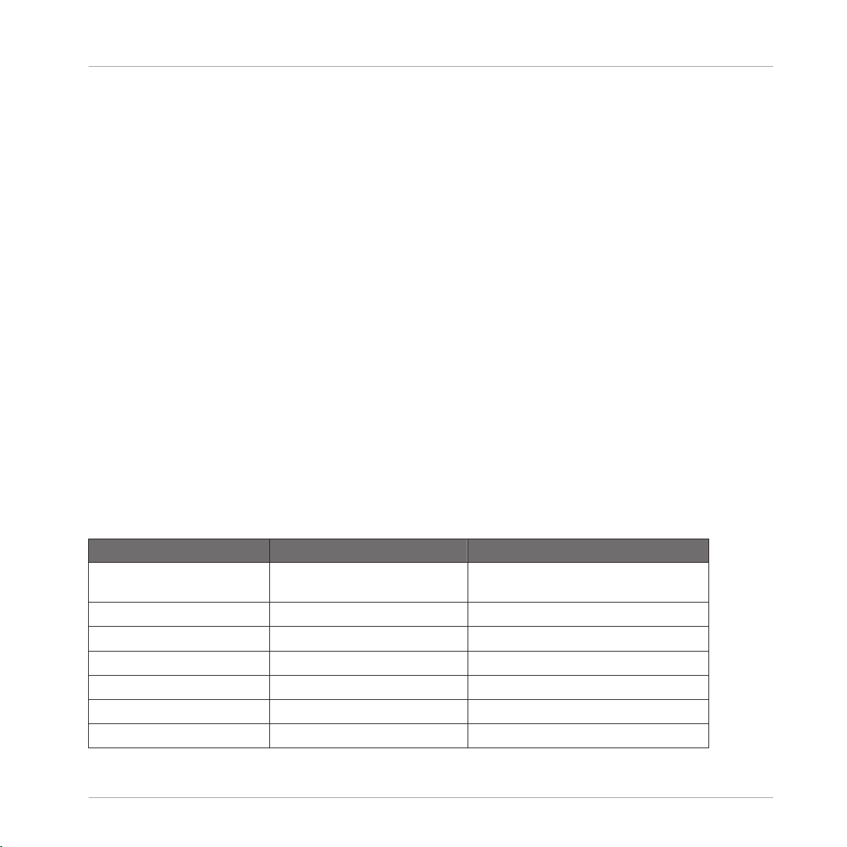
For each NI controller, the following table shows you how to switch to/from MIDI mode and
how to quickly see whether your controller currently is in MIDI mode or not:
NI Controller Switching to/from MIDI mode Checking that MIDI mode is on
KOMPLETE KONTROL S-SERIES
MASCHINE SHIFT + CONTROL SHIFT button dimly lit
MASCHINE MK2 SHIFT + CONTROL SHIFT button dimly lit
MASCHINE MIKRO SHIFT + F1 SHIFT button dimly lit
MASCHINE MIKRO MK2 SHIFT + F1 SHIFT button dimly lit
MASCHINE STUDIO SHIFT + CHANNEL SHIFT button dimly lit
TRAKTOR KONTROL S2 SHIFT + SHIFT (on both Decks) Both SHIFT buttons dimly lit
SHIFT + INSTANCE Both PRESET buttons lit
CONTROLLER EDITOR - Manual - 19
Page 20
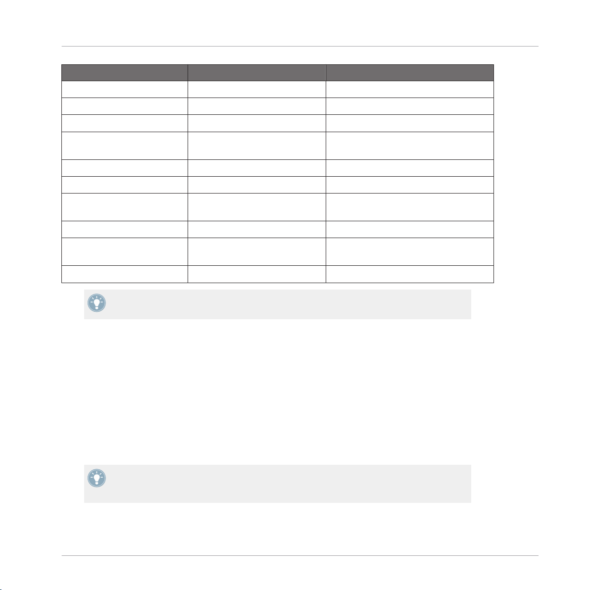
Switching your NI Controller to MIDI Mode
NI Controller Switching to/from MIDI mode Checking that MIDI mode is on
TRAKTOR KONTROL S2 MK2 SHIFT + SHIFT (on both Decks) Both SHIFT buttons dimly lit
Quick Start
TRAKTOR KONTROL S4 SHIFT + BROWSE button
TRAKTOR KONTROL S4 MK2 SHIFT + PREVIEW button
TRAKTOR KONTROL S8 SHIFT (any Deck) + BACK (right
Deck)
TRAKTOR KONTROL D2 SHIFT (any Deck) + BACK SHIFT button dimly or fully lit
TRAKTOR KONTROL X1 SHIFT + HOTCUE HOTCUE button lit in green
TRAKTOR KONTROL X1 MK2 SHIFT + Load (both left and right
buttons)
TRAKTOR KONTROL F1 SHIFT + BROWSE SHIFT button lit
TRAKTOR KONTROL Z1 MODE + CUES (ensure both A &
B headphone cues are pressed)
TRAKTOR KONTROL Z2 SHIFT + Settings Settings button lit
Please find more information on this in the respective controller-specific chapters, later in
this manual.
Loop Size Displays reading “ON”
Loop Size Displays reading “ON”
Both SHIFT buttons dimly or fully lit
SHIFT button lit
MODE button lit
Switch to MIDI Mode by Starting the Controller Editor
You can also switch all your connected NI controllers to MIDI mode by starting the Controller
Editor:
Start the Controller Editor by selecting Start > All Programs > Native Instruments > Con-
►
troller Editor > Controller Editor (Windows) or Applications > Native Instruments > Controller Editor (Mac OS X).
This not only opens the Controller Editor, but also automatically switches any connected
→
controller(s) to MIDI mode.
If the Controller Editor is already open, you can check at any time whether your NI controller is in MIDI mode or not, and if not, switch it back to MIDI mode via the Device menu
and the Connect button nearby — see ↑3.2.1, Select the NI Controller below.
CONTROLLER EDITOR - Manual - 20
Page 21
Loading MIDI Assignments
Whichever method you have used, when switching your controller(s) to MIDI mode, the MIDI
assignments last used are automatically loaded along with their last state of use. If you are
starting the Controller Editor for the first time, the default MIDI assignments for your controller(s) are loaded instead.
You can start right away using your NI controller as a MIDI remote control!
3.2 Loading MIDI Assignments
In order to load other MIDI assignments for your NI controller, we will use the Controller Editor.
As already mentioned, this can also be done from most NI controllers — see the controllerspecific chapters, later in this manual.
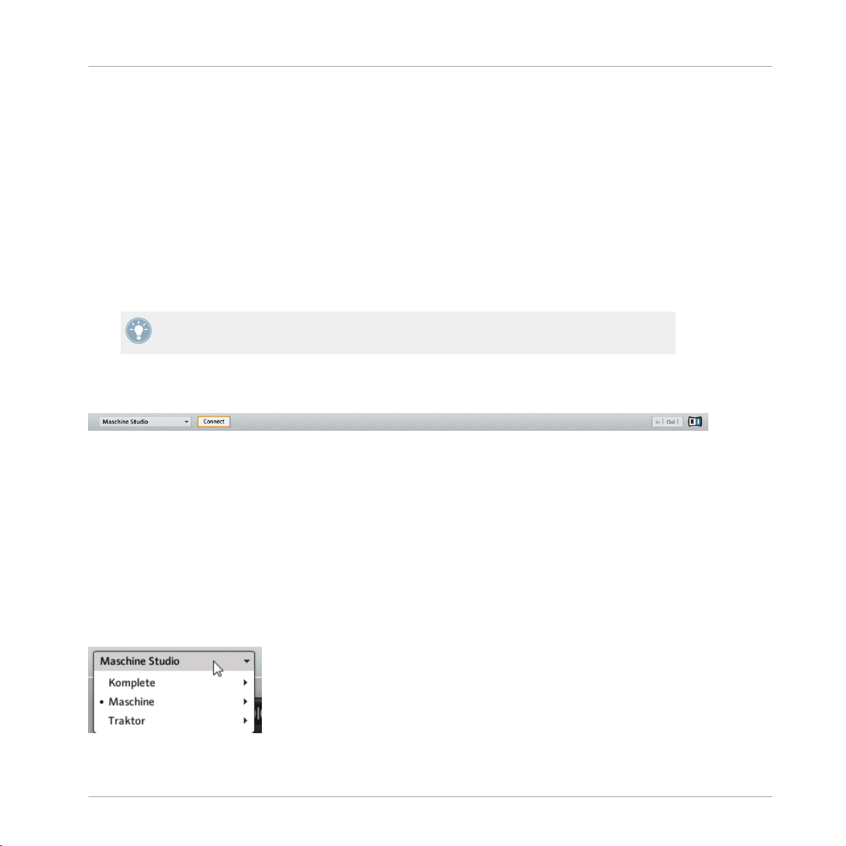
At the top of the Controller Editor window, you see a horizontal bar with a series of controls
ending in the NI logo at the far right. We call this bar the Application Control Bar:
The Application Control Bar, at the top of the Controller Editor window.
Quick Start
We will use the Application Control Bar to start loading new MIDI assignments.
3.2.1 Select the NI Controller
We first have to select the NI controller for which we want to load the MIDI assignments.
To select a controller:
Click the Device menu (the first control from the left in the Application Control Bar), and
►
select the desired controller in the menu.
Choose your NI controller in the Device menu.
CONTROLLER EDITOR - Manual - 21
Page 22
Loading MIDI Assignments
Here a few points of interest about the Device menu and the controller selection:
• In the menu both the folder containing the controller connected to your computer and the
name of the controller itself are indicated by a leading dot (•) in front of their name.
• Upon your selection, the menu closes and displays the name of the controller that you
just selected.
• The large controller picture below the menu is updated accordingly. This area is called
Hardware area — we will get back to it later.
The selection made in this Device menu does not affect in any way whether your NI controllers are in MIDI mode or not. Its sole purpose is to select a controller for loading,
changing, and managing its MIDI assignments.
Optional: Check that the Selected Controller Is in MIDI Mode
Besides looking at your NI controller to see if it’s in MIDI mode (see ↑3.1, Switching your NI
Controller to MIDI Mode), you can also check the Controller Editor interface:
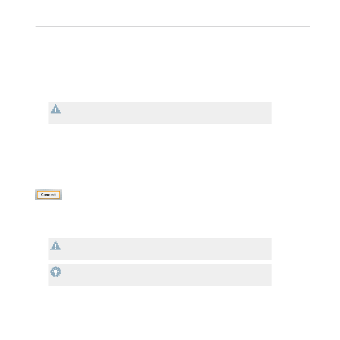
Next to the Device menu in the Application Control Bar, you can check that the Connect
►
button is lit, indicating that the selected NI controller is in MIDI mode (and thus is connected to the Controller Editor).
Quick Start
The Connect button lights up when your NI controller is in MIDI mode.
If the Connect button is unlit for any reason (for example, if you have started the MASCHINE
or TRAKTOR software after the Controller Editor), you can click it at any time to re-connect the
selected controller with the Controller Editor and switch it back to MIDI mode.
If the Connect button is grayed out and inactive, your NI controller might be disconnected
from your computer. Check the USB connection — if your controller is connected, ensure
that its drivers are properly installed (for more information, see chapter ↑2, Installation).
Your NI controller does not necessarily have to be in MIDI mode or even connected to your
computer in order to work on its MIDI assignments. This notably allows you to work on the
MIDI assignments even if your controller is not to hand at the moment.
CONTROLLER EDITOR - Manual - 22
Page 23
Loading MIDI Assignments
3.2.2 Select a Template
We will now select a Template — a full set of assignments for all assignable control elements
on your NI controller.
For more information on the Templates, see ↑4.3, The Mapping System.
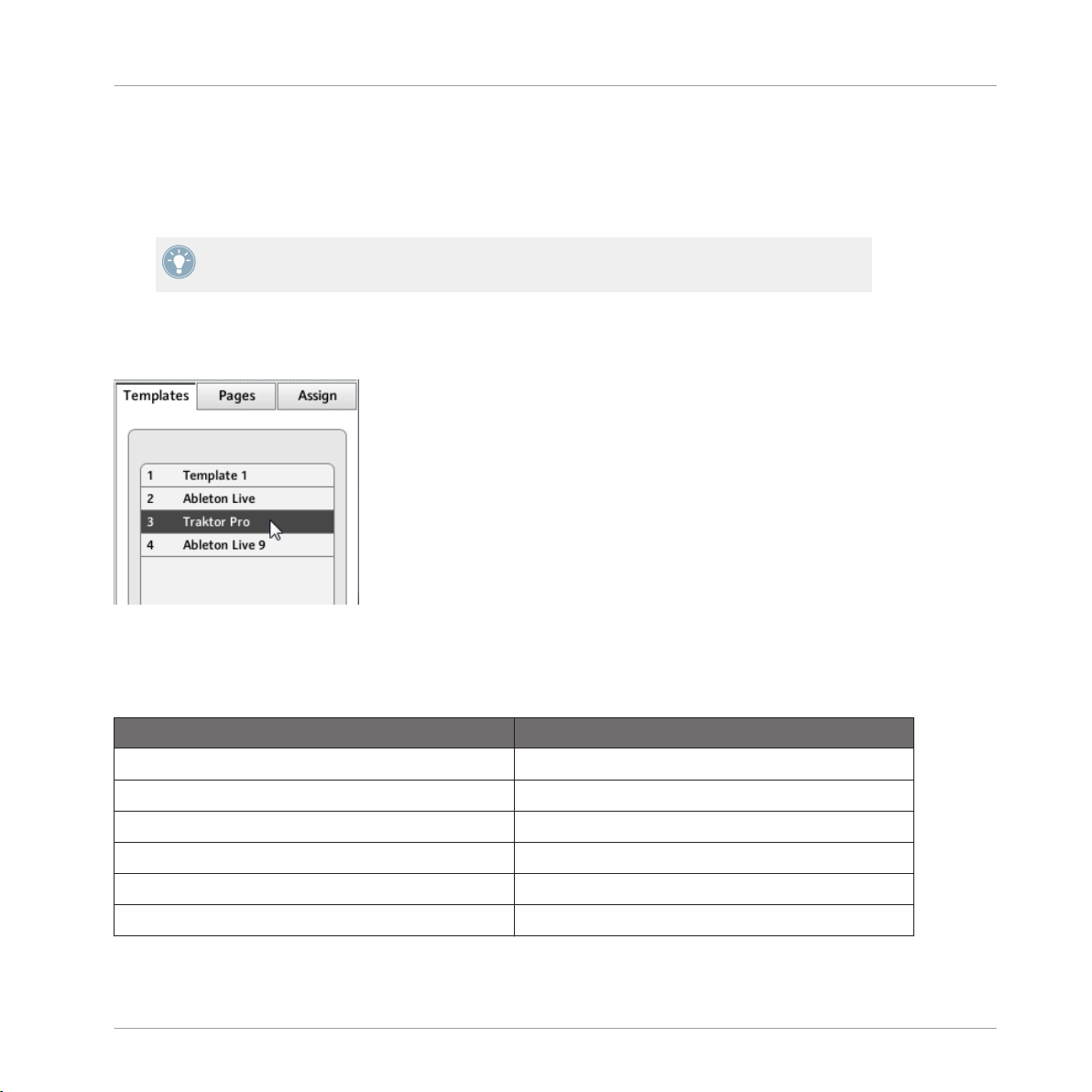
On the right of the application, click the Templates tab and choose a Template in the list
►
that appears underneath.
Quick Start
The Template list allows you to load the desired Template.
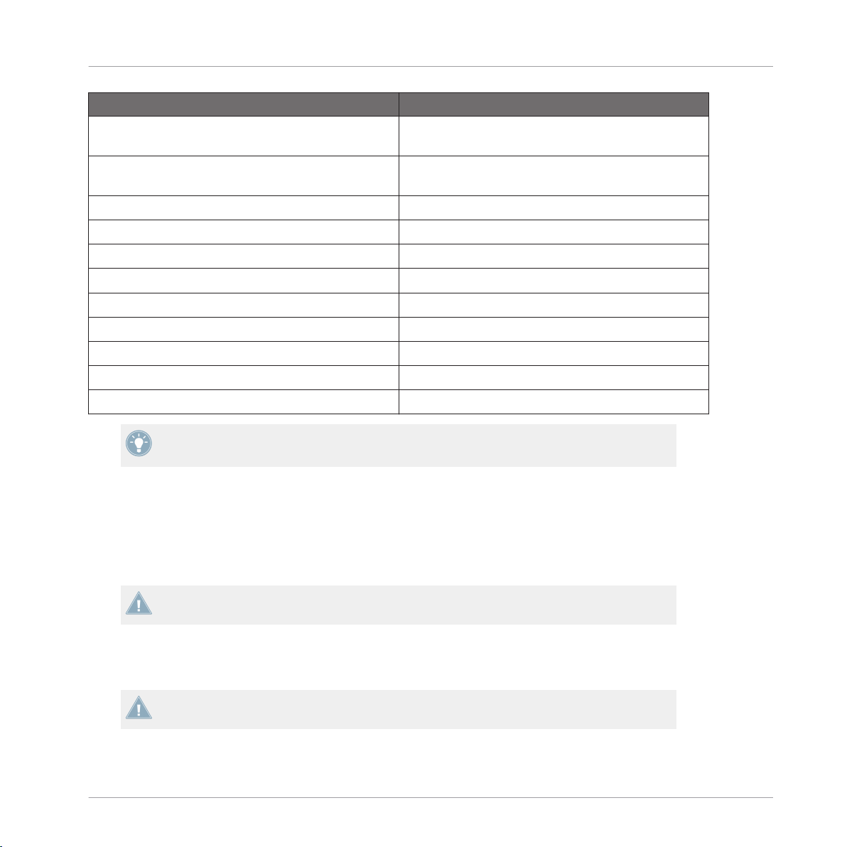
From the Hardware
Some NI controllers also allow you to select Templates via following shortcuts:
NI Controller Template Selection
KOMPLETE KONTROL S-SERIES PRESET buttons
MASCHINE STUDIO SHIFT + Page buttons
MASCHINE MK2 SHIFT + Page buttons
MASCHINE SHIFT + Page buttons
MASCHINE MIKRO MK2 SHIFT + Left/Right Arrow buttons
MASCHINE MIKRO SHIFT + Left/Right Arrow buttons
CONTROLLER EDITOR - Manual - 23
Page 24
Loading MIDI Assignments
NI Controller Template Selection
TRAKTOR KONTROL D2 Performance Mode buttons (left/right arrows on either
side of the displays)
TRAKTOR KONTROL S8 Performance Mode buttons (left/right arrows on either
side of the displays)
TRAKTOR KONTROL S4 n/a
TRAKTOR KONTROL S4 MK2 n/a
TRAKTOR KONTROL S2 n/a
TRAKTOR KONTROL S2 MK2 n/a
TRAKTOR KONTROL X1 n/a
TRAKTOR KONTROL X1 MK2 n/a
TRAKTOR KONTROL F1 n/a
TRAKTOR KONTROL Z1 n/a
TRAKTOR KONTROL Z2 n/a
More information on this in the respective controller-specific chapters, later in this manual.
Quick Start
Either way, the Template will automatically be loaded upon selection and its assignments will
be displayed. You can now control the new target from your NI controller.
Each assignment is recalled at the last state of use: the software automatically saves the last
value for each of the control elements assigned in this Template. When you load a Template
for the first time all assignments are at their default value.
TRAKTOR KONTROL S2: You can skip the following sections and directly go to ↑3.2.5,
Ready to Go?.
3.2.3 Select a Page
TRAKTOR KONTROL S2: There are no Pages available for this controller. Hence, you can
skip this section.
CONTROLLER EDITOR - Manual - 24
Page 25
Loading MIDI Assignments
KOMPLETE KONTROL S-SERIES: Only one Page is available and it is always selected.
Hence, you can skip this section. Multiple Pages will be available in a future KOMPLETE KONTROL update.
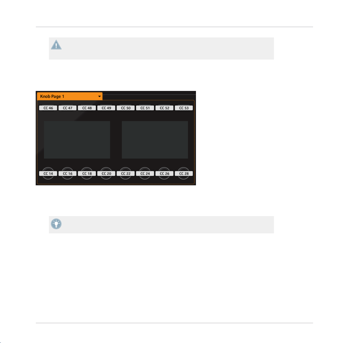
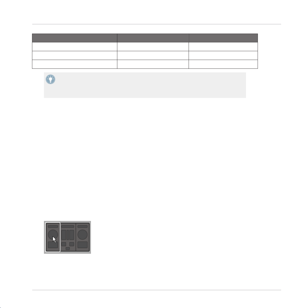
Within each Template, some (or all) of the control elements of your NI controller can have multiple assignments, organized into Pages. In the Hardware area, these control elements are indicated by a frame surrounding them.
Quick Start
The orange frame representing the Knob Page in the Hardware area for the MASCHINE STUDIO controller (detail).
At any time there is one active Page, i.e. one active subset of assignments for these specific
control elements.
For more information on the Pages, see ↑4.3, The Mapping System.
Thus, let’s select a particular Page of assignments for loading:
To select a Page, click the Page menu (the orange menu above the orange frame in the
►
picture above) and select the desired Page in the list.
CONTROLLER EDITOR - Manual - 25
Page 26
Loading MIDI Assignments
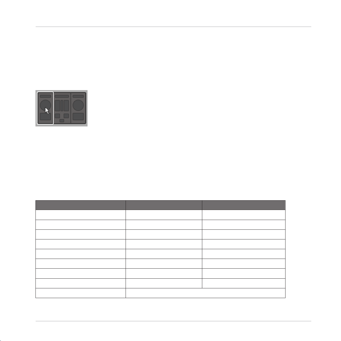
TRAKTOR KONTROL S2 MK2, S4 (MK2), and S8: the Overview Panel
Due to their great size and number of control elements, the TRAKTOR KONTROL S2 MK2, S4
(MK2) and TRAKTOR KONTROL S8 are divided into three parts in the Controller Editor: left
Deck, Mixer, and right Deck. Thus, before selecting any Page on these controllers, you first
have to choose a specific part for displaying. This is done via the Overview, at the top left corner of the Hardware area:
Use the Overview to select the desired Deck (S4 depicted).
You have two Pages at your disposal for each Deck. To select a specific Page:
1. Click the left or right Deck in the Overview.
2. Click the Page menu (the orange menu above the orange frame) and select the desired
Page in the list.
Quick Start
From the Hardware
You can also select Pages from your NI controller:
NI Controller
KOMPLETE KONTROL S-SERIES 1 n/a
MASCHINE (MK2) Unlimited Page buttons
MASCHINE MIKRO (MK2) Unlimited Left/Right Arrow buttons
MASCHINE STUDIO Unlimited Left/Right Arrow buttons
TRAKTOR KONTROL D2 2 for each Deck A–D DECK and/or SHIFT
TRAKTOR KONTROL S8 2 for each Deck A–D DECK and/or SHIFT
TRAKTOR KONTROL S4 2 for each Deck A–D DECK C/D then SHIFT
TRAKTOR KONTROL S4 MK2 2 for each Deck A–D DECK C/D then SHIFT
TRAKTOR KONTROL S2 n/a
# of Available Pages Page Switch/Selection
CONTROLLER EDITOR - Manual - 26
Page 27
Loading MIDI Assignments
NI Controller # of Available Pages Page Switch/Selection
TRAKTOR KONTROL S2 MK2 2 for each Deck A–B SHIFT
TRAKTOR KONTROL X1 2 SHIFT
TRAKTOR KONTROL X1 MK2 2 SHIFT
TRAKTOR KONTROL F1 2 SHIFT
TRAKTOR KONTROL Z1 Unlimited n/a
TRAKTOR KONTROL Z2 2 SHIFT
More information on this in the controller-specific chapters, later in this manual.
3.2.4 Select a Pad Page (MASCHINE Controller Family Only)
The sixteen pads of your MASCHINE STUDIO, MASCHINE (MK2) or MASCHINE MIKRO
(MK2) controller can optionally have multiple assignments, too. These are also organized into
pages: the Pad Pages. The Pad Page feature can be activated at the Template level: you can
have some Templates without Pad Pages (i.e. with one assignment each pad) and some other
with Pad Pages (i.e. with several assignments for each pad).
Quick Start
In the Hardware area, provided that the Pad Page feature is activated in the current Template,
the Pad Page is indicated by a blue frame around the pads:
CONTROLLER EDITOR - Manual - 27
Page 28
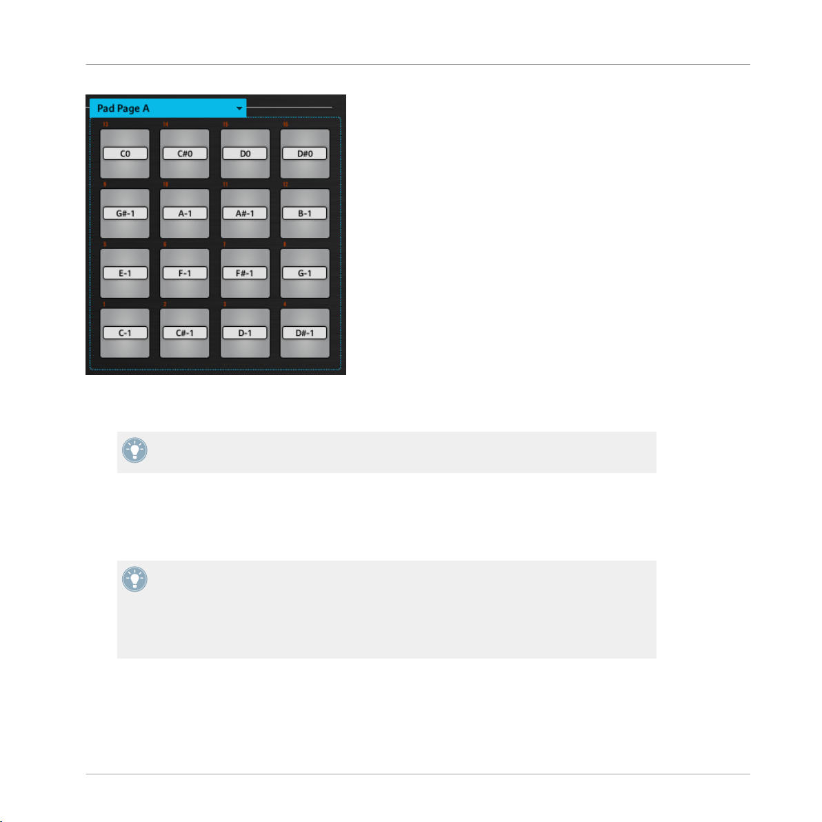
The blue frame representing the Pad Page in the Hardware area for the MASCHINE controller family (detail).
At any time there is one active Pad Page, i.e. one subset of assignments for the pads.
Quick Start
Loading MIDI Assignments
For more information on the Pad Pages, see ↑4.3, The Mapping System.
Thus, let’s select a particular Pad Page of assignments for loading:
To select a Pad Page, click the Pad Page menu (the blue menu above the blue frame) and
►
select the desired Pad Page in the list.
MASCHINE STUDIO: Your MASCHINE STUDIO controller offers another two optional paging systems: the I/O and Level Pages can store multiple assignments for the Level knob in
the Master section, and the Jog Wheel Pages can store multiple assignments for the jog
wheel and its LED ring. For more details, see section ↑4.3.4, I/O and Level Pages (MA-
SCHINE STUDIO Only) and ↑4.3.5, Jog Wheel Pages (MASCHINE STUDIO Only), respec-
tively.
From the Hardware
You can also select Pad Pages from your controller:
CONTROLLER EDITOR - Manual - 28
Page 29
Loading MIDI Assignments
NI Controller # of Available Pad Pages Pad Page Selection
MASCHINE STUDIO 8 (if feature activated) Group buttons A–H
MASCHINE (MK2) 8 (if feature activated) Group buttons A–H
MASCHINE MIKRO (MK2) 8 (if feature activated) GROUP + pads 9–16
Fore more information on the available commands on your controller, see chapter ↑5, Using
Your MASCHINE Controller, ↑6, Using Your MASCHINE MK2 Controller, ↑7, Using Your
MASCHINE MIKRO Controller, ↑8, Using Your MASCHINE MIKRO MK2 Controller, or ↑9,
Using Your MASCHINE STUDIO Controller.
3.2.5 Ready to Go?
If you only plan to use a Template as it is, i.e. without modifying any of its MIDI assignments,
you’re done! As you may have noticed, you can do all this from within your MASCHINE Controller, TRAKTOR KONTROL S8 or KOMPLETE KONTROL S-SERIES — this of course being the
preferred way for any live situation. If you used the Controller Editor, you can close the application now: the corresponding NI background service will take care of everything and you can
start using your NI controller as a MIDI remote control right away!
Quick Start
3.3 Modifying an Assignment
Now, if you want to modify some of the assignments stored in the selected Template (and possibly one of its Pages), continue with these few more steps:
1. TRAKTOR KONTROL S2 (MK2) / S4 (MK2) / S8 only: In the Overview at the top left,
click the part of the controller (left Deck, Mixer, or right Deck) containing the control element whose assignment you want to edit.
CONTROLLER EDITOR - Manual - 29
Page 30
Modifying an Assignment
2. Select the desired control element. You can do this in two ways: In the Controller Editor,
click the control element within the hardware representation (a double-click on the control element directly brings the Inspector’s Assign pane to the front for faster editing, see
next step). You can also [Shift]-click several control elements of the same type (or click
and drag a rectangle) to select them. Or, on your NI controller (except KOMPLETE KONTROL S-SERIES), touch the control element (for this, the Touch Select option must be
enabled in File > Preferences > General — this is the case by default).
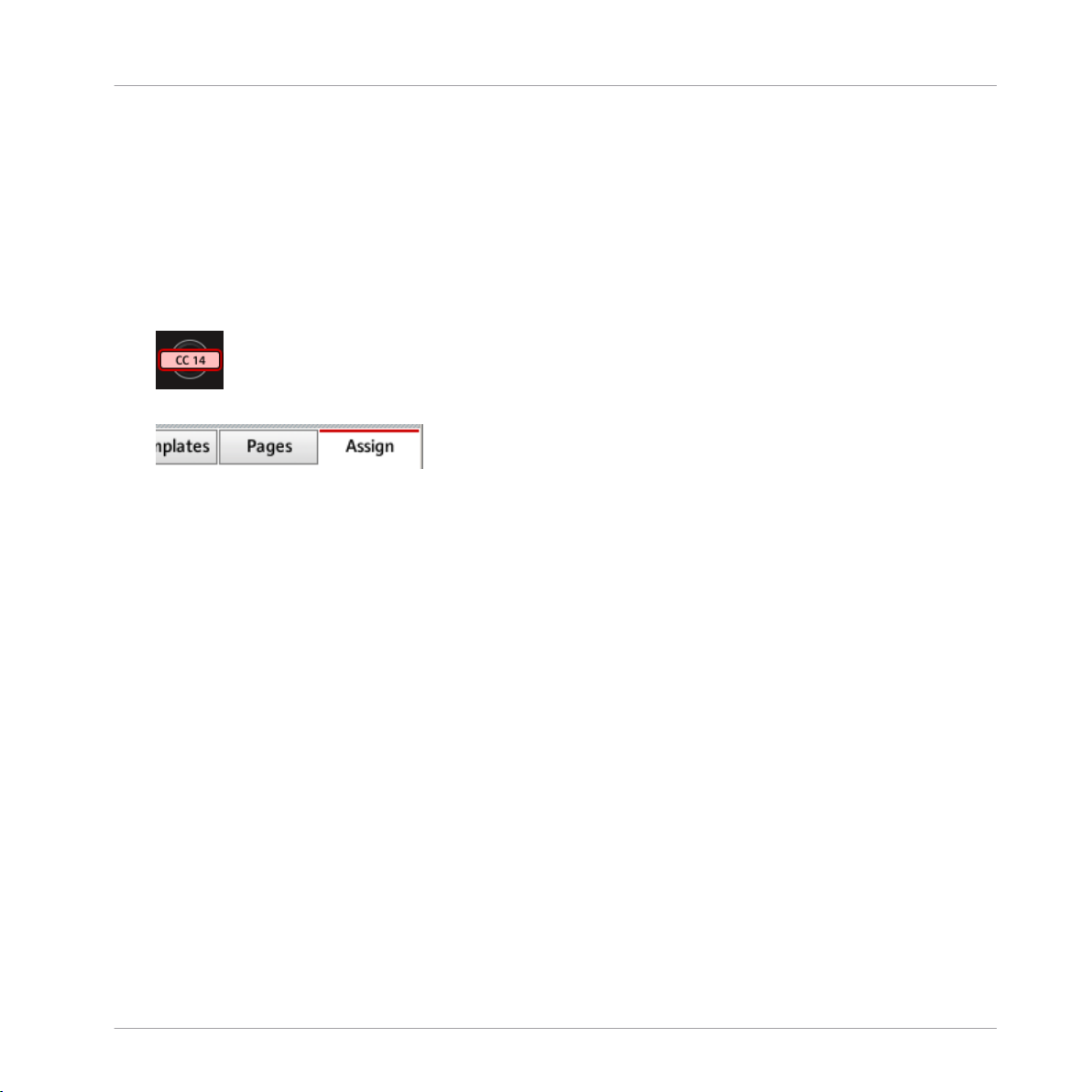
Either way, the control elements selected for editing get surrounded by the red Selection
Frame in the Controller Editor window:
3. In the Inspector (the right part of the Controller Editor interface), click the Assign tab:
The Assign pane opens up and displays all assignments’ properties for the selected control element(s).
4. Modify the assignment’s properties according to your needs: at the top, you can edit the
name of the assignment, and below, all MIDI properties like the type of MIDI message to
be sent, the MIDI channel to use, and so on. The assignment’s details will differ depending on the type of MIDI message you choose.
Quick Start
CONTROLLER EDITOR - Manual - 30
Page 31

That’s it! Now the corresponding control element on your NI controller triggers the MIDI
→
message that you just defined.
Quick Start
Organizing Your Assignments
3.4 Organizing Your Assignments
Thanks to its powerful mapping system, the Controller Editor lets you organize your assignments as you like. You can define Templates and Pages to address various situations: For example, you could define different Pages to control different instruments in your setup. Furthermore, you could prepare different Templates for different songs in your live performance, with
all necessary Pages inside.
3.4.1 Displaying the Lists of Templates and Pages
To manage (create, delete, duplicate, etc.) your Templates and Pages, use the first two tabs of
the Inspector, namely Templates and Pages.
CONTROLLER EDITOR - Manual - 31
Page 32

Organizing Your Assignments
The Templates tab and Pages tab allow you to organize your assignments.
• On the Templates pane, you find a list of all available Templates (both factory and userdefined), along with an Edit menu holding all managing commands (e.g. New, Duplicate,
Delete, etc.). Below, you can see a few additional settings for the selected Template —
these settings vary with each NI controller.
• On the Pages pane, an equivalent list is available for the (Knob) Pages and, only for the
MASCHINE controllers, for the Pad Pages (and other Page types on the MASCHINE STUDIO), along with their corresponding Edit menus.
The Page functionality is not available on the TRAKTOR KONTROL S2.
For the TRAKTOR KONTROL X1 (MK2), F1, S2 MK2, S4 (MK2), S8 and for Z2, there is no
Edit menu available under the Pages list — instead, there is a Shift Mode menu available.
For more information on this, see the controller-specific chapters, later in this manual.
KOMPLETE KONTROL S-SERIES: Only one Page is available and it is always selected.
Multiple Pages will be available in a future KOMPLETE KONTROL update.
Quick Start
3.4.2 Renaming Templates and Pages
Let’s say you have just defined a Knob Page that controls one of your software synthesizers.
You might want to rename it so that you easily remember its purpose:
1. In the Knob Pages list, double-click the Page that you just defined (let’s say Knob Page
3). Its name gets highlighted.
2. Type a new name for this Page (for example, “Absynth Lead”) and press [Enter] on your
computer keyboard to confirm the change:
CONTROLLER EDITOR - Manual - 32
Page 33

Organizing Your Assignments
3.4.3 Re-ordering Templates and Pages
You may want to put this Page at the top of the list, e.g. if you plan to use this synthesizer at
first in your song and want to have direct access to its parameters from your Controller:
1. Click the Page Absynth Lead in the list, hold the mouse button depressed and drag your
mouse toward the top of the list. An insertion line appears to show you the position where
the Page is going to be moved to.
2. When the insertion line reaches the top of the list (or the desired insertion position, wherever it is), release the mouse button. The Page “Absynth Lead” takes its new position in
the list.
The Pages for the TRAKTOR KONTROL X1 (MK2), F1, S2 MK2, S4 (MK2), S8, and the Z2
cannot be reordered.
This process can also be applied to the other Pages as well as to the Templates (on the Tem-
plates pane). The Edit menus offer more managing features — you will find all details later in
this manual (mainly sections ↑23.5.1, Templates Pane and ↑23.5.2, Pages Pane). For a detailed description of the mapping system, please refer to section ↑4.3, The Mapping System.
Quick Start
3.5 Saving and Loading Templates
Once you have defined a set of assignments that suits your needs, you have the possibility to
save it.
Actually, you don’t necessarily need to save it, since the Controller Editor automatically saves
the changes made to the Template you are working on (and its included Pages and single assignments). So if you only plan to use this Template later on the same computer, you can quit
the Controller Editor, the Template will be recalled with all modifications next time you switch
your NI controller to MIDI mode and select this Template.
You may want to use a modified or a newly created Template on another computer or you may
want to share your Template with other users. In that case, you can export a Template as a
Template file:
CONTROLLER EDITOR - Manual - 33
Page 34

Saving and Loading Templates
1. Go to the Templates pane of the Inspector and select the desired Template by clicking its
entry in the Template list. The selected Template is highlighted:
2. Below the list, click the Edit menu and select Export:
Quick Start
3. In the Save template dialog that opens, choose the destination and type the name of the
Template file to be exported. Please note that the filename that you choose can be different from the Template’s name inside the Controller Editor. Once this is done, click Save
to export the file and you’re done.
Template filenames have various extensions depending on the affected NI controller.
Please see ↑4.3.6, Templates for a list of filename extensions.
You can now transfer this Template file to another computer, share it with a friend, etc.
On the other hand, as you would expect, the Controller Editor also allows you to load a Template file. To do this:
1. In the Templates pane of the Inspector, click the Edit menu and select Open. An Open
template dialog appears that lets you navigate through your file system on your computer
and choose a Template file to import.
2. Select the desired Template file and click Open. The Template is loaded and appended to
your Template list.
CONTROLLER EDITOR - Manual - 34
Page 35

Saving and Loading Templates
The Controller Editor provides many factory Templates for use with various MIDI targets.
Please refer to the Controller Editor Template Documentation to know how to use them!
Quick Start
CONTROLLER EDITOR - Manual - 35
Page 36

Basic Concepts
How the Controller Editor Works
4 Basic Concepts
In this chapter we will introduce you to the basics of the Controller Editor. You might have already checked the previous chapter, which gives you a first idea of how to use the Controller
Editor. Here, we will approach the system in a more general way.
4.1 How the Controller Editor Works
The Controller Editor allows you to define the links between your NI controller and the audio
applications running on your computer or your external MIDI devices. It lets you decide how
your actions on the NI controller will be interpreted. For this purpose, the Controller Editor implements a powerful mapping system allowing you to define as many MIDI assignments as you
want for each control element (knob, button, etc.) available on your NI controller.
The Controller Editor works in conjunction with a small background service installed on your
computer during the Controller Editor installation procedure. This background service takes
care of all communication matters between your NI controller and your MIDI-capable targets,
both on the software side and on the hardware side. It stays active even if you close the Controller Editor application, which means you don’t need the Controller Editor open on your computer to use your NI controller as a MIDI remote control! You can select and/or tweak your assignments in the Controller Editor and then quit the application — the assignments (and Templates / Pages, see below) stay active thanks to this small background service. Thus, the Controller Editor can be seen as an assignment editor: use it to check or edit your assignments.
4.2 Overview of the User Interface
Now let’s look closely at the Controller Editor user interface. When you start the Controller Editor, you will see the application containing a Template, something like this:
CONTROLLER EDITOR - Manual - 36
Page 37

Basic Concepts
Overview of the User Interface
The Controller Editor user interface: the big view (Windows version pictured, with the MASCHINE STUDIO controller in the
Hardware area)
The user interface is divided into four main areas, namely:
(1) Application Menu Bar
(2) Application Control Bar
(3) Hardware area
(4) Inspector
In the following sections you will find a brief introduction to all areas of the software and their
corresponding control elements. For a detailed description of each of these elements, please
refer to chapter ↑23, Reference.
CONTROLLER EDITOR - Manual - 37
Page 38

Basic Concepts
Overview of the User Interface
4.2.1 Application Menu Bar
At the top of the Controller Editor window (or at the top of your computer screen on Mac OS X),
the Application Menu Bar is similar to the one found with most applications on your operating
system. Here it consists of three menus (File, View, and Help) controlling the general functions
of the software:
The Application Menu Bar (Windows version pictured)
4.2.2 Application Control Bar
Right under the Application Menu Bar, the Application Control Bar holds menus and buttons
controlling the overall mapping system:
The Application Control Bar
From left to right, we have the following controls:
(1) Device menu: Allows you to select the controller of which you want to edit the MIDI assignments.
(2) Connect button: Allows you to “call” your hardware — in other words, to switch it to MIDI
mode and connect it to the Controller Editor, in case it is currently connected to its dedicated
software.
(3) MIDI Activity indicator (except for KOMPLETE KONTROL S-SERIES keyboards): Shows any
incoming/outgoing MIDI data for the controller selected in the Device menu (1).
(4) NI Logo: Opens the About screen.
4.2.3 Hardware Area
Below the Application Control Bar is the Hardware area. The Hardware area is the largest part
of the user interface and basically represents your NI controller and all its control elements —
most of them are freely assignable to MIDI messages.
CONTROLLER EDITOR - Manual - 38
Page 39

Basic Concepts
Overview of the User Interface
The Controller depicted in the Hardware area corresponds to the device selected in the Device
menu located in the Application Control Bar (see above).
Click an assignable control element in the Hardware area to edit its assignment.
►
Compared to your real NI controller, the Hardware area holds a few additional graphical elements:
• Every control element that can be assigned to a MIDI message comes with a Label Field
which displays a name (describing by default its current assignment).
Pairs of mini buttons in the Hardware area: If mini buttons are not selected when you click
them, click their Label Field instead!
• A red Selection Frame highlights the selected control element(s).
• An orange Page (or Knob Page) menu allows you to select a particular Page (or Knob
Page) of assignments. The Page (or Knob Page) area, denoted by an orange frame, holds
the control elements affected by the Page (or Knob Page) selection in the menu. Please
refer to section ↑4.3.2, Pages (or Knob Pages) for more information on this.
The Page feature is not available on the TRAKTOR KONTROL S2.
• MASCHINE controllers only: If the Pad Page feature is activated, an additional blue Pad
Page menu allows you to select a particular page of assignments for the pads. The blue
frame highlights the Pad Page area, which holds the control elements included in the Pad
Pages — namely the pads. Please refer to section ↑4.3.3, Pad Pages (MASCHINE Con-
troller Family Only) for more information on this.
• MASCHINE STUDIO only: If the I/O and Level Page feature is activated, an additional red
I/O and Level Page menu allows you to select a particular assignment for the Level knob
(in the Master section of your controller). The red frame surrounds the control elements
involved in the I/O and Level Pages. Please refer to section ↑4.3.4, I/O and Level Pages
(MASCHINE STUDIO Only) for more information on this.
• MASCHINE STUDIO only: If the Jog Wheel Page feature is activated, an additional violet
Jog Wheel Page menu allows you to select a particular assignment for the jog wheel and
its LED ring. The violet frame highlights the jog wheel. Please refer to section ↑4.3.5, Jog
Wheel Pages (MASCHINE STUDIO Only) for more information on this.
CONTROLLER EDITOR - Manual - 39
Page 40

Basic Concepts
Overview of the User Interface
• TRAKTOR KONTROL S2 (MK2) / S4 (MK2) / S8 only: At the upper left corner, the little
Overview allows you to select a specific part of your controller for displaying and editing
(left Deck, Mixer, or right Deck). The Hardware area displays the part of the S2/S4/S8
that you selected here.
You will find a detailed description of each Hardware area / NI controller and its assignable
control elements in the respective controller-specific chapters, later in this manual.
4.2.4 Inspector
At the right of the Hardware area, the Inspector is the control tower of your mapping system.
There, you can precisely define what has to be done on your target when you press, turn, or
move anything on your NI controller. Moreover, you can organize all your assignments into Pages and Templates. Section ↑23.5, The Inspector will give you a detailed description of all
what you can do with the Inspector.
The Inspector is divided into three panes, each of them controlling a specific part of the mapping scheme: the Templates pane, the Pages pane, and the Assign pane.
The Templates Pane
The Templates pane allows you to manage your Templates. It shows a list of available Templates along with a few editing functions.
A Template holds a whole mapping configuration for all control elements of your NI controller. For more information, see ↑4.3.6, Templates below.
CONTROLLER EDITOR - Manual - 40
Page 41

Basic Concepts
Overview of the User Interface
The Templates pane in the Inspector (here for the MASCHINE controller)
The Templates pane holds the following elements, from top to bottom:
(1) Template list: Shows all available Templates with, for each Template, an index number (not
editable) and a name (editable). There, you can select a Template for editing by clicking its
name, and modify its name by double-clicking it.
(2) Template Edit menu and Factory Templates menu: The Edit menu provides you with editing
functions like New, Save As, etc. The Factory Templates menu allows you to load factory Templates.
(3) Template Properties area: Gives you access to the properties of the Template that is currently selected in the upper Template list.
The Template Properties area is available only for certain NI controllers.
CONTROLLER EDITOR - Manual - 41
Page 42

Basic Concepts
Overview of the User Interface
The Pages Pane
The Pages pane allows you to manage your Pages. Pages are sets of assignments focused on
certain areas of your NI controller. Therefore, each NI controller will have different sets of Pages.
This feature is not available on TRAKTOR KONTROL S2 — if you are currently working on
a Template for this controller, you cannot activate the Pages pane (the tab is grayed out).
Pages are sets of assignments for specific control elements. For more info, see ↑4.3.2, Pa-
ges (or Knob Pages), ↑4.3.3, Pad Pages (MASCHINE Controller Family Only), ↑4.3.4, I/O
and Level Pages (MASCHINE STUDIO Only), and ↑4.3.5, Jog Wheel Pages (MASCHINE STUDIO Only).
CONTROLLER EDITOR - Manual - 42
Page 43

Basic Concepts
Overview of the User Interface
The Pages pane in the Inspector for the MASCHINE STUDIO controller.
The Pages pane holds the following elements:
(1) Knob Pages list or Pages list: Shows a list with all available (Knob) Pages with, for each of
them, an index number (uneditable) and a name (editable). There, you can select a Page for
editing by clicking its name, and modify its name by double-clicking it. On the MASCHINE
controllers, you can rearrange the page order via drag and drop. You can also select a Page via
the orange (Knob) Page menu in the Hardware area, or possibly from your NI controller.
CONTROLLER EDITOR - Manual - 43
Page 44

Basic Concepts
Overview of the User Interface
(2) Knob Page Edit menu or Page Edit menu: Provides you with editing functions for the (Knob)
Pages like New, Duplicate, etc.
For some NI controllers, this Edit menu is replaced with a Shift Mode menu with the two
options Gate and Toggle allowing you to choose the behavior of the SHIFT button when
switching between Pages from your controller. For more information on this, see the controller-specific chapters, later in this manual.
The following elements are available only if you are working on the assignments for either of
the MASCHINE controllers:
(3) Enable Pad Pages button: Activates/deactivates the Pad Page feature. If the Pad Page feature is deactivated, the rest of the area is minimized and grayed out. It will not be possible to
interact with the Pad Pages when they are deactivated.
(4) Pad Page list: Shows a list with all available Pad Pages with, for each of them, an index
number (uneditable) and a name (editable). There, you can select a Pad Page for editing by
clicking its name, and modify its name by double-clicking it. You can rearrange the page order
via drag and drop. You can also select a Pad Page via the Pad Page menu above the pads in
the Hardware area, or from your controller: On the MASCHINE (MK2) and MASCHINE STUDIO
controllers, use the Group buttons labeled A to H; on the MASCHINE MIKRO (MK2) controller,
hold the GROUP button and use pad 9–16.
(5) Pad Page Edit menu: Provides you with editing functions like New, Duplicate, etc.
The following elements are available only if you are working on the assignments for the MASCHINE STUDIO:
(6) Enable I/O and Level Pages button: Activates/deactivates the I/O and Level Page feature. If
the I/O and Level Page feature is deactivated, the rest of the area is minimized and grayed out.
It will not be possible to interact with the I/O and Level Pages when they are deactivated. On
the other hand, this will make the eight Input/Output buttons available for MIDI assignments.
(7) I/O and Level Pages list: Shows a list with all available I/O and Level Pages. Each page will
have an index number (uneditable) and a name (editable). You can select a I/O and Level Page
for editing by clicking its name, and modify its name by double-clicking it. You can rearrange
the page order via drag and drop. You can also select a I/O and Level Page via the I/O and Level Pages menu above the Level knob in the Hardware area, or on your MASCHINE STUDIO
controller when in MIDI mode.
CONTROLLER EDITOR - Manual - 44
Page 45

Basic Concepts
Overview of the User Interface
(8) I/O and Level Page Edit menu: Provides you with editing functions for the I/O and Level Pages
like New, Duplicate, etc.
(9) Jog Wheel Pages button: Activates/deactivates the Jog Wheel Page feature. If the Jog Wheel
Page feature is deactivated, the rest of the area is minimized and grayed out. It will not be
possible to interact with the Jog Wheel Pages when they are deactivated. On the other hand,
this will make the FUNCTION buttons available for MIDI assignments.
(10) Jog Wheel Page list: Shows a list with all available Jog Wheel Pages. Each page will have
an index number (uneditable) and a name (editable). You can select a Jog Wheel Page for editing by clicking its name, and modify its name by double-clicking it. You can rearrange the
page order via drag and drop. You can also select a Jog Wheel Page via the Jog Wheel Page
menu above the jog wheel in the Hardware area, or using the FUNCTION buttons on your MASCHINE STUDIO controller when in MIDI mode.
(11) Jog Wheel Page Edit menu: Provides you with editing functions for the Jog Wheel Pages like
New, Duplicate, etc.
The Assign Pane
The last pane in the Inspector is the Assign pane. This is where you specify all details of the
assignment for a particular control element. This pane shows the properties of the currently selected control element:
CONTROLLER EDITOR - Manual - 45
Page 46

Basic Concepts
Overview of the User Interface
The Assign pane in the Inspector.
The Assign pane shows different properties depending on the type of element currently selected.
(1) Description area: This area is similar for all control elements. It shows the following information about the currently selected control element:
• The index number and the name of the Page of the selected control element (this is empty for elements not included in a Page).
• The element description (not editable) and its name (editable).
MASCHINE controller family: Depending on the controller and the selected control element, an additional setting can be available in the Description area. See section ↑23.5.3,
Assign Pane for more details.
(2) Definition area: Defines the MIDI assignment properties for the current control element.
Please refer to section ↑23.5.3, Assign Pane in the reference chapter for more information.
CONTROLLER EDITOR - Manual - 46
Page 47

Basic Concepts
The Mapping System
4.3 The Mapping System
Whatever you do on your NI controller, the Controller Editor translates it into a MIDI message
that is then sent to the desired MIDI port — this is what the Controller Editor is all about:
mapping human actions to MIDI events.
The Controller Editor’s mapping system is structured in a way that allows you to efficiently organize your assignments. This makes the whole mapping process a lot easier and informs you
about what will happen whenever you actuate a control element on your NI controller. The next
paragraphs will introduce you to some basic concepts.
4.3.1 Assignments
An assignment defines which MIDI event is triggered by a particular control element. Available
MIDI event types are “MIDI Note,” “MIDI CC,” etc. Every action on a control element is translated into one MIDI event, the corresponding assignment defines the rules of that translation.
Depending on the type of control element (button, knob, pad, fader, encoder, pedal input,
footswitch…), the available assignments differ. For more details about all available assignments for each type of control, please refer to section ↑23.6, MIDI Message Parameters.
4.3.2 Pages (or Knob Pages)
Pages are not available on TRAKTOR KONTROL S2.
For some of the control elements, you can have multiple assignments, organized in Pages (also
called Knob Pages on specific NI controllers). Those particular control elements are located in
the (Knob) Page area — indicated by the orange frame in the Hardware area, see section
↑4.2.3, Hardware Area above. A (Knob) Page is a set of assignments for all control elements in
this (Knob) Page area. One (Knob) Page can be selected (and loaded) at a time.
You can switch the available (Knob) Pages — either built-in or user-defined — via the Page
menu (or Knob Page menu) in the Hardware area or via the Page list (or Knob Page list) in the
Inspector. You can do it as well from your NI controller — more on this in the respective chapters describing the use of each NI controller.
CONTROLLER EDITOR - Manual - 47
Page 48

Basic Concepts
The Mapping System
When you select another (Knob) Page, all assignments for the control elements in the (Knob)
Page area are updated accordingly. All (Knob) Pages are stored as an editable list on the Pages
pane of the Inspector (for detailed information about the Inspector, see ↑23.5, The Inspector).
4.3.3 Pad Pages (MASCHINE Controller Family Only)
On the MASCHINE STUDIO, MASCHINE (MK2), and MASCHINE MIKRO (MK2) controllers,
you also have access to optional pages of assignments dedicated to the pads: the Pad Pages.
The Pad Pages work like the Pages and Knob Pages explained above, but they affect the sixteen pads instead of the control elements in the (Knob) Page area.
The number of Pad Pages is limited to eight. One Pad Page can be selected at a time. When
you select another Pad Page, all assignments for the sixteen pads are updated accordingly. The
eight available Pad Pages are stored as an editable list on the Pages pane in the Inspector (you
will find all details about the Inspector in section ↑23.5, The Inspector).
The Pad Pages can be activated or deactivated, depending on your needs, via the Enable Pad
Pages button in the Inspector’s Pages pane:
• If activated, you can switch the available Pad Pages via the Pad Page menu (in the Hardware area) or via the Pad Page list (in the Inspector). Again, you can do it as well from
your NI controller, via the Group buttons (labeled from A to H) or, for MIKRO controllers,
via the GROUP button and pads 9–16)..
• If deactivated, only one assignment can be set for each pad. The Group buttons A–H (or
the GROUP button on MIKRO controllers) can then be also assigned to MIDI commands.
4.3.4 I/O and Level Pages (MASCHINE STUDIO Only)
On the MASCHINE STUDIO controller, you also have access to optional pages of assignments
dedicated to the I/O and Level section: the I/O and Level Pages. The eight available I/O and
Level Pages allow you to store eight different assignments for the Level knob. Only one I/O and
Level Page can be selected at a time.
The I/O and Level Pages can be activated or deactivated via the Enable I/O and Level Pages
button in the Inspector’s Pages pane (you will find all details about the Inspector in section
↑23.5, The Inspector):
CONTROLLER EDITOR - Manual - 48
Page 49

Basic Concepts
The Mapping System
• If activated, you can switch the available I/O and Level Pages by pressing the Input buttons (IN1, IN2, IN3, IN4) and Level meter buttons (MST, GRP, SND, CUE) on your controller. The lit button indicates which I/O and Level page is currently active. You can also
do this in the Controller Editor via the I/O and Level Page menu (in the Hardware area) or
the I/O and Level Page list (in the Inspector).
• If deactivated, only one assignment can be set for the Level knob. The Input and Level
meter buttons can then be also assigned to MIDI commands.
4.3.5 Jog Wheel Pages (MASCHINE STUDIO Only)
On the MASCHINE STUDIO controller, you also have access to optional pages of assignments
dedicated to the jog wheel and its LED ring: the Jog Wheel Pages. The six available Jog Wheel
Pages allow you to store six different assignments for the jog wheel and its LED ring. Only one
Jog Wheel Page can be selected at a time.
The Jog Wheel Pages can be activated or deactivated via the Enable Jog Wheel Pages button in
the Inspector’s Pages pane (you will find all details about the Inspector in section ↑23.5, The
Inspector):
• If activated, you can switch the available Jog Wheel Pages by pressing the FUNCTION
buttons (under the jog wheel) on your controller. The lit LED near the jog wheel (EDIT,
CHANNEL, BROWSE, TUNE, SWING or VOLUME) indicates which Jog Wheel Page is currently active. You can also do this in the Controller Editor via the Jog Wheel Pages menu
(in the Hardware area) or the Jog Wheel Page list (in the Inspector).
• If deactivated, only one assignment can be set for the jog wheel and its LED ring. The
FUNCTION buttons can then be also assigned to MIDI commands.
4.3.6 Templates
A Template holds a mapping configuration for all control elements on your NI controller, including the (Knob) Pages, Pad Pages, I/O and Level Pages and Jog Wheel Pages that might
exist. One Template can be selected at a time. The Template also determines if the generated
MIDI events have to be sent to the internal MIDI port (to access an application listening to
MIDI on your computer) or to the external MIDI port (to access an external MIDI-capable device) — only for controllers that are equipped with MIDI ports of course. Switching between
different Templates can be used, for example, to address different applications on your computer or different hardware instruments.
CONTROLLER EDITOR - Manual - 49
Page 50

Basic Concepts
The Mapping System
The Template contains all Knob Page/Pad Page/I/O and Level Page/Jog Wheel Page data, the
list of Knob Pages/Pad Pages/I/O and Level Pages/Jog Wheel Pages and the index of the last
selected Knob Page/Pad Page/I/O and Level Page/Jog Wheel Page. The Template also stores
the last state of each control element.
Templates can be stored as distinct files on your computer. These files have the following extensions:
NI Controller Template file extension
KOMPLETE KONTROL S-SERIES .nckk
MASCHINE .ncm
MASCHINE MK2 .ncm2
MASCHINE MIKRO .ncmm
MASCHINE MIKRO MK2 .ncmm2
MASCHINE STUDIO .ncmst
TRAKTOR KONTROL X1 .nckx1
TRAKTOR KONTROL X1 MK2 .nckx1m2
TRAKTOR KONTROL F1 .nckf1
TRAKTOR KONTROL Z1 .nckz1
TRAKTOR KONTROL Z2 .nckz2
TRAKTOR KONTROL D2 .nckd2
TRAKTOR KONTROL S8 .ncks8
TRAKTOR KONTROL S4 .ncks4
TRAKTOR KONTROL S4 MK2 .ncks4m2
TRAKTOR KONTROL S2 .ncks2
TRAKTOR KONTROL S2 MK2 .ncks2m2
You can switch among the available Templates (either built-in or user-defined) via the Template list in the Templates pane of the Inspector. This can also be done from some NI controllers — more on this in the respective chapters describing the use of each NI controller.
When you select another Template, all assignments for all control elements of the controller
are updated accordingly, including the Pages, if any.
CONTROLLER EDITOR - Manual - 50
Page 51

Basic Concepts
The Mapping System
The Controller Editor provides many factory Templates for use with various MIDI targets.
Please refer to the Controller Editor Template Documentation for more information about
using them.
4.3.7 Configuration
For each NI controller, a working set of data contains all listed Templates, with all included
pages and assignments, and the index of the currently selected Template.
The working data sets for all controllers can be stored as a single Configuration file on your
computer. This type of file has the extension “.ncc.”
4.4 To Sum Up…
By utilizing your NI controller and the Hardware Service (the Controller Editor and the NI background service) you can remotely control any MIDI target. The Hardware Service was designed
in a way that allows you to forget its presence in a live situation: After having configured your
assignments, you can rely on your NI controller to allow you to control everything you need during your performance. Triggering MIDI hardware devices and applications in various ways,
switching in real time to other sets of assignments (or groups thereof), all this can be done directly from your NI controller.
In fact, the only thing that you can not do from the Controller is modify your assignments… For
that, you will need to use the Controller Editor! But thanks to the powerful mapping scheme
using Templates and Pages, which is partly mirrored on your NI controller, you can prepare as
many assignments as you want and recall them instantly during your live performance.
In the next chapters, we will show you how to use your NI controller(s) with the assignments
defined within the Controller Editor.
CONTROLLER EDITOR - Manual - 51
Page 52

Using Your MASCHINE Controller
5 Using Your MASCHINE Controller
In this chapter, we will focus on what’s happening on your MASCHINE controller. By reading
this, you will learn:
• How to use the basic controls on your controller for navigating through the MIDI mapping
system.
• The list of all assignable control elements on your controller.
• How the various luminous elements give you some important information about their
state.
• How to use the powerful displays of your MASCHINE controller in MIDI mode.
To enjoy full functionality of your NI controller as a MIDI remote control, especially concerning some control elements’ state and LED behavior, you need to tell your NI controller
what is the current state of the parameter in the MIDI target. You can do this by setting up
MIDI feedback channels coming from your MIDI target back to your NI controller. This way,
your controller will always stay up-to-date with the current parameter values in your target
software/hardware. For more information on how to configure these MIDI feedback channels, please refer to your target software/hardware’s documentation.
Basic Controls
5.1 Basic Controls
This section shows you the commands available on your MASCHINE controller for basic tasks:
switching between MIDI mode and MASCHINE mode, and selecting sets (Templates) and subsets (Knob Pages, Pad Pages) of MIDI assignments.
All these actions can of course be done via the Controller Editor user interface — see chapter ↑3, Quick Start for example. Nevertheless, using your NI controller instead can be very
handy in a live situation!
CONTROLLER EDITOR - Manual - 52
Page 53

Selection Command
MIDI/MASCHINE mode
Templates SHIFT +
Knob Pages Page but-
SHIFT +
CONTROL
Page buttons
tons
Using Your MASCHINE Controller
Basic Controls
Pad Pages
(if activated)
Display mode SHIFT +
Group
buttons
Buttons
1–8
For more information on Templates, Knob Pages, and Pad Pages, see ↑4.3, The Mapping
System.
CONTROLLER EDITOR - Manual - 53
Page 54

Using Your MASCHINE Controller
Assignable Control Elements
For more information on the display modes, see ↑5.4, The Displays. There you will also
learn another way to select and load Templates and Knob Pages from your controller.
When your MASCHINE controller is in MIDI mode, its SHIFT button is dimly lit.
Adjusting Settings for your Controller
You can adjust various settings for your MASCHINE controller by entering its Settings display
mode or by going to File > Preferences > Controller. See ↑5.4.7, Settings Display Mode for
more information.
5.2 Assignable Control Elements
If you selected the MASCHINE controller in the Device menu of the Application Control Bar,
this is what the Hardware area looks like:
CONTROLLER EDITOR - Manual - 54
Page 55

Using Your MASCHINE Controller
Assignable Control Elements
The Hardware area representing the MASCHINE controller.
In this Hardware area, you will notice the Knob Page menu and its associated Knob Page area
(orange frame), the Pad Page menu and its associated Pad Page area (blue frame), and the red
Selection Frame on the currently selected control element (pad 10 in the picture above).
The MASCHINE controller holds the following areas:
The names that you see on the device only refer to their original function in the MASCHINE
software. We use these names here only to describe the interface!
CONTROLLER EDITOR - Manual - 55
Page 56

Using Your MASCHINE Controller
Assignable Control Elements
(1) Page buttons and buttons around: In the top left part, you find a set of eight buttons arranged
into four rows of two buttons. From these eight buttons, six are freely assignable (CONTROL
and STEP, BROWSE and SAMPLING, SNAP (F1), and AUTO WRITE (F2)) and two have special functions: the left and right Page buttons (see previous section).
(2) MASTER area: The MASTER area holds four freely assignable control elements (three knobs
and one button).
(3) GROUPS area: The GROUPS area contains eight buttons labeled from A to H: the Group but-
tons. If you activated the Enable Pad Pages button in the Pages pane of the Inspector, these
buttons allow you to select the desired page of assignments for the pads (see ↑4.3.3, Pad Pa-
ges (MASCHINE Controller Family Only)). If you didn’t activate the Pad Pages, these eight but-
tons are freely assignable to MIDI events.
(4) TRANSPORT area: The TRANSPORT area contains eight buttons. Seven of them are freely
assignable: RESTART (LOOP), Previous, Next, GRID, PLAY, REC, and ERASE. The last one,
SHIFT, is a special button (see previous section). Therefore, this button cannot be assigned in
the Controller Editor.
(5) Knob Page area: The Knob Page area holds a set of eight buttons and eight knobs, with the
buttons being placed above and the knobs below the two displays, respectively. These sixteen
control elements are freely assignable. The Knob Page area is indicated by an orange frame
and headed by the Knob Page menu.
The buttons and knobs in the Knob Page area can also have other functions according to
the display mode that is currently active. See ↑5.4, The Displays for more on this.
(6) PADS area: The PADS area shows a column of eight freely assignable buttons (namely
SCENE, PATTERN, PAD MODE (KEYBOARD), NAVIGATE, DUPLICATE, SELECT, SOLO, and
MUTE) as well as a square of sixteen freely assignable pads. If you activated the Enable Pad
Pages button in the Pages pane of the Inspector, a Pad Page area (indicated by the blue
frame) groups the pads together and is headed by the Pad Page menu.
To Sum Up…
All control elements on your MASCHINE controller are freely assignable to MIDI events (with
the limitations due to the type of control element), with the following exceptions:
• The Page buttons and the SHIFT button have a predefined function (see previous section).
CONTROLLER EDITOR - Manual - 56
Page 57

Using Your MASCHINE Controller
Visual Feedback on Your Controller
• The Group buttons, labeled A to H, are not assignable if you use the Pad Page feature —
they’re used for selecting Pad Pages, see previous section. If you deactivate the Pad Pages, the Group buttons are freely assignable like any other.
You can also split the controls of your controller between MIDI mode and MASCHINE mode
in order to control a MASCHINE plug-in instance while sending MIDI messages to the host
with the transport controls! See ↑23.5.1, Templates Pane for more information.
Assignment Parameters
The following table summarizes where to find all assignment details for each type of control
element on your controller:
Type of Control Element Assignment Parameters
Buttons ↑23.6.2, Assignments for Buttons
Pads – Hit action ↑23.6.4, Assignments for the Pads – Hit Action
Pads – Press action ↑23.6.6, Assignments for the Pads – Press Action
Knobs ↑23.6.8, Assignments for Analog Encoders
5.3 Visual Feedback on Your Controller
The fast bidirectional communication between your MASCHINE controller and the Hardware
Service on the software side allows status indications on your controller to be made in real
time.
Your MASCHINE controller provides you visual feedback in various ways:
• All buttons and pads are equipped with LEDs that inform you about the assignment state
of the control element at any time.
• The displays show you additional information about the assignments.
5.3.1 Buttons
The LEDs below each button can have three states: off, dimmed and bright. Their lighting behavior depends on the type and state of the control element.
The following table indicates you the possible states for the LEDs:
CONTROLLER EDITOR - Manual - 57
Page 58

Using Your MASCHINE Controller
Visual Feedback on Your Controller
Button State LED State
Not assigned Off
Assigned – Off state Dimmed
Assigned – On state Bright
For buttons in Increment mode, the Off state corresponds to the zero value, while the On
state corresponds to a value greater than zero. See section ↑23.6.2, Assignments for But-
tons for more information on the various button modes.
Controlling the Button State
The On/Off state of each button can be controlled in two ways — internally via your actions on
the button, or remotely via MIDI feedback:
• In Toggle mode, both controls are enabled: both your actions on the button and the possibly incoming MIDI messages are taken into account to update the button and LED state.
• In Trigger, Gate, and Increment mode, you can choose which control mode (internal or remote via MIDI) you want to use. This is done via the LED On menu in the Assign pane of
the Inspector.
For more information on the button modes, LED On menu, and MIDI feedback mode, see
↑23.6.2, Assignments for Buttons.
Moreover, for the Buttons 1–8 above the displays, the particular assignment is shown within
the displays in Knobs display mode (see section ↑5.4.2, Knobs Display Mode).
5.3.2 Pads
Here are the rules for the pads. Since the pads have two functions (they are pressure-sensitive), the states are indicated as follows:
• If the pad is not assigned, it is off.
• If there is an assignment for the Hit action, the pad’s LED behaves like that of a button
(see previous section).
CONTROLLER EDITOR - Manual - 58
Page 59

Using Your MASCHINE Controller
Visual Feedback on Your Controller
• If the Hit action is not assigned but the Press action is assigned to the Note message
type, the LED has a low brightness to show the Off state and a high brightness to show
the On state. For all other message types, the LED stays at low brightness.
5.3.3 Knobs
The assignments for the eight Knobs under the displays are indicated within the displays in
Knobs display mode. If a Knob is not assigned, the display reads “OFF.”
The VOLUME, TEMPO and SWING knobs in the MASTER area have no display, but, like for all
other controls, their value is shown in the displays in the Event line of the Monitor display
mode.
For more information on the various display modes on your MASCHINE controller, see next
section.
5.4 The Displays
The displays on your MASCHINE controller can show different parts of your mapping configuration, depending on the display mode that is activated. Each display mode modifies the behavior of Buttons 1–8 above the displays and Knobs 1–8 below them. Learn more about the different display modes available for the MASCHINE controller in the following sections.
5.4.1 Switching Between Display Modes
First of all, to switch between display modes, press the SHIFT button on your MASCHINE controller and hold it. On the displays, you see something like this:
The displays on your MASCHINE controller in MIDI mode, when the SHIFT button is depressed.
CONTROLLER EDITOR - Manual - 59
Page 60

Using Your MASCHINE Controller
This screen allows you to select the desired display mode. On the top, you find six fields representing the six display modes, from left to right: MONITOR, SETTINGS, KNOBS, PADS, PAGE, and TEM-
PLATE.
To switch to any of the display modes, hold the SHIFT button and press the correspond-
►
ing Button 3–8 above the displays.
At any time, you can press the SHIFT button again and switch to another display mode.
In the middle part of the left display, you see the name of the current Template. This is common to all display modes (except the Settings display mode), so that you can always be sure
about which Template is currently selected.
Below, a message reminds you that you can switch to another Template simply by pressing the
Page buttons, since you are already holding SHIFT (see ↑5.1, Basic Controls).
5.4.2 Knobs Display Mode
The Knobs display mode is probably the one you will use the most. In this mode, the displays
show the currently loaded Knob Page, with its eight button assignments on the top row and its
eight knob assignments on the bottom row:
The Displays
The Knobs display mode mirrors the currently loaded Knob Page.
This display mode allows you to see which MIDI message is currently assigned to each control
element in the loaded Knob Page. In this mode, the 16 control elements around the displays
(Buttons 1–8 above and Knobs 1–8 below) trigger the MIDI messages assigned to them.
Each field mirrors the Label Field as defined in the Inspector’s Assign pane for the corresponding control element: the name you defined there appears here — if you haven’t defined any
name for that control element yet, its label is simply its assigned MIDI message.
In the lower row, the displays additionally show the current value for each Knob. These values
can be displayed in two views: either via numerical values (like in the picture above), or via
small bars:
CONTROLLER EDITOR - Manual - 60
Page 61

Using Your MASCHINE Controller
The Knobs display mode with bars instead of numerical values.
You can switch between the two views by holding the SHIFT button and turning Knob 5:
1. Hold SHIFT (thus getting to the switching screen explained ↑5.4.1, Switching Between
Display Modes).
You can see the option “SHOW BARS” or “SHOW VALUES” above Knob 5 (depending on which
view is currently selected).
2. Turn Knob 5 to select the desired view.
3. Release SHIFT.
The new view is displayed.
→
Note that depending on the assignment properties for each of the Knobs, its displayed value
(or bar) can either be going from 0 to 127 or from -63 to 64 (bipolar) — this second setting
can be useful for some types of controls (e.g. a stereo balance). This only affects the value/bar
shown on the displays — the real MIDI value will go from 0 to 127 anyway. Please refer to
section ↑23.6.8, Assignments for Analog Encoders for more information on this.
The Displays
5.4.3 Pad Pages Display Mode
The Pad Pages display mode (labeled “PADS” on the displays) allows you to check the current
assignations for the pads of your MASCHINE controller, by mirroring the current Pad Page:
The Pad Pages display mode mirrors the Pad Page currently loaded.
On the left display, you find some general information about the loaded Template, Knob Page
and Pad Page. The right display summarizes the pads’ assignments stored in the active Pad
Page.
CONTROLLER EDITOR - Manual - 61
Page 62

Using Your MASCHINE Controller
5.4.4 Knob Pages Display Mode
The Knob Pages display mode allows you to switch between Knob Pages:
The Knob Pages display mode allows you to switch between Knob Pages.
On the left display, you find the usual general information about the currently loaded Template, Knob Page and Pad Page.
On the right display, you see the list of your Knob Pages, as defined in the Knob Pages list of
the Inspector’s Pages pane.
1. Use Buttons 5 and 6 above the up and down arrows to scroll through the list and find the
Knob Page you wish to load next. You can also turn Knob 5.
When you have it, press Button 8 (“LOAD”) to load the selected Knob Page.
2.
Actually, this functionality is already available in many ways: in the Controller Editor, you can
use the Knob Page menu (in the Hardware area) or the Knob Pages list (in the Inspector’s
Pages pane), and on the MASCHINE controller you have the Page buttons at your disposal. But
the Knob Pages display mode allows you a greater control over the Knob Page selection from
the MASCHINE controller:
The Displays
• Unlike the Knob Page menu and Knob Pages list, you don’t have to open the Controller
Editor to switch to another Knob Page.
• Unlike the Page buttons on your controller, you can quietly choose the next Knob Page to
be loaded, even if it’s not the one right after/before the Knob Page currently loaded. You
can check its name to remember its assignments, and you can scroll the entire list to find
the page you want.
When you reach the end of a list while scrolling, you can choose whether the selection has
to jump at the other end of the list or stay on this last item. This can be set in Preferences
> General > Wrap Template and Page Lists.
CONTROLLER EDITOR - Manual - 62
Page 63

Using Your MASCHINE Controller
5.4.5 Template Display Mode
The Template display mode allows you to switch between Templates.
The Template display mode allows you to switch between Templates.
On the left display, you find the same general information about the Template, Knob Page and
Pad Page currently loaded.
On the right display, you see the list of your Templates, as defined in the Inspector’s Tem-
plates pane.
1. Use Button 5 and 6 above the up and down arrows to scroll through the list and find the
Template you wish to load next. You can also turn Knob 5.
When you have it, press Button 8 (“LOAD”) to load the selected Template.
2.
Like for the Knob Pages, this functionality is already available in many ways: in the Controller
Editor you can use the Template list (in the Inspector’s Templates pane), and on the MASCHINE controller you can press SHIFT + Page buttons. The Template display mode allows
you a greater control over the Template selection from your controller though, for the reasons
explained as those explained in the previous section for the Knob Pages.
The Displays
5.4.6
Monitor Display Mode
The Monitor display mode provides you with useful information about the MIDI data sent by
your MASCHINE controller.
The Monitor display mode provides information about the MIDI data sent by your MASCHINE controller.
CONTROLLER EDITOR - Manual - 63
Page 64

Using Your MASCHINE Controller
The left display shows the usual information about the current Template, Knob Page and Pad
Page.
The right display shows two lines:
• The Control line indicates the control element that you are currently actuating.
• The Event line shows the details of the MIDI event being currently sent by this control element.
This display mode is very useful to monitor what’s going out of your controller, for example for
debugging purpose: if something goes wrong somewhere in your MIDI chain, you can check
here what is actually sent by your MASCHINE controller.
5.4.7 Settings Display Mode
The Settings display mode allows you to adjust relevant parameters and provides information
about your MASCHINE controller.
The Displays
The Settings display mode provides access to parameters for your MASCHINE controller.
The settings are grouped in the left display. They are the same as in File > Preferences > Con-
troller (when the MASCHINE controller is selected in the Controller menu at the top, of
course). The settings are:
• Brightness: Changes the backlight of the displays.
• Pad Sensitivity: Changes the sensitivity of the pads.
• Contrast L: Sets the contrast for the left display.
• Contrast R: Sets the contrast for the right display.
The right display provides you with some important information about your MASCHINE controller and the Hardware Service:
• In the upper part, you find the firmware version of your MASCHINE controller along with
its serial number.
CONTROLLER EDITOR - Manual - 64
Page 65

Using Your MASCHINE Controller
• In the bottom part of the display, you see the version numbers of the NI Hardware Service
and hardware drivers.
The Displays
CONTROLLER EDITOR - Manual - 65
Page 66

Using Your MASCHINE MK2 Controller
6 Using Your MASCHINE MK2 Controller
In this chapter, we will focus on what’s happening on your MASCHINE MK2 controller. By
reading this, you will learn:
• How to use the basic controls on your controller for navigating through the MIDI mapping
system.
• The list of all assignable control elements on your controller.
• How the various luminous elements give you some important information about their
state.
• How to use the powerful displays of your MASCHINE MK2 controller in MIDI mode.
To enjoy full functionality of your NI controller as a MIDI remote control, especially concerning some control elements’ state and LED behavior, you need to tell your NI controller
what is the current state of the parameter in the MIDI target. You can do this by setting up
MIDI feedback channels coming from your MIDI target back to your NI controller. This way,
your controller will always stay up-to-date with the current parameter values in your target
software/hardware. For more information on how to configure these MIDI feedback channels, please refer to your target software/hardware’s documentation.
Basic Controls
6.1 Basic Controls
This section shows you the commands available on your MASCHINE MK2 controller for basic
tasks: switching between MIDI mode and MASCHINE mode, and selecting sets (Templates)
and subsets (Knob Pages, Pad Pages) of MIDI assignments.
All these actions can of course be done via the Controller Editor user interface — see chapter ↑3, Quick Start for example. Nevertheless, using your NI controller instead can be very
handy in a live situation!
CONTROLLER EDITOR - Manual - 66
Page 67

Selection Command
MIDI/MASCHINE
mode
Templates SHIFT + Page buttons
Knob Pages Page buttons
SHIFT + CONTROL
Using Your MASCHINE MK2 Controller
Basic Controls
Pad Pages
(if activated)
Display mode SHIFT + Buttons 3–8
For more information on Templates, Knob Pages, and Pad Pages, see ↑4.3, The Mapping
System.
For more information on the display modes, see ↑6.4, The Displays. There you will also
learn another way to select and load Templates and Knob Pages from your controller.
Group buttons
When your MASCHINE MK2 controller is in MIDI mode, its SHIFT button is dimly lit.
CONTROLLER EDITOR - Manual - 67
Page 68

Using Your MASCHINE MK2 Controller
Assignable Control Elements
Adjusting Settings for your Controller
You can adjust various settings for your MASCHINE MK2 controller by entering its Settings
display mode or by going to File > Preferences > Controller. See ↑6.4.6, Settings Display Mode
for more information.
6.2 Assignable Control Elements
If you selected the MASCHINE MK2 controller in the Device menu of the Application Control
Bar, this is what the Hardware area looks like:
CONTROLLER EDITOR - Manual - 68
Page 69

Using Your MASCHINE MK2 Controller
Assignable Control Elements
The Hardware area representing the MASCHINE MK2 controller.
In this Hardware area, you will notice the Knob Page menu and its associated Knob Page area
(orange frame), the Pad Page menu and its associated Pad Page area (blue frame), and the red
Selection Frame on the currently selected control element (pad 1 in the picture above).
The MASCHINE MK2 controller holds the following areas:
The names that you see on the device only refer to their original function in the MASCHINE
software. We use these names here only to describe the interface!
CONTROLLER EDITOR - Manual - 69
Page 70

Using Your MASCHINE MK2 Controller
Assignable Control Elements
(1) Page buttons and buttons around: In the top left part, you find a set of eight buttons arranged
into four rows of two buttons. From these eight buttons, six are freely assignable (CONTROL
and STEP, BROWSE and SAMPLING, ALL, and AUTO WR.) and two have special functions:
the left and right Page buttons (see previous section).
(2) MASTER area: The MASTER area holds eight freely assignable control elements (seven but-
tons and the Control encoder).
(3) GROUPS area: The GROUPS area contains eight buttons labeled from A to H: the Group but-
tons. If you activated the Pad Pages button in the Pages pane of the Inspector, these buttons
allow you to select the desired page of assignments for the pads (see ↑4.3.3, Pad Pages (MA-
SCHINE Controller Family Only)). If you didn’t activate the Pad Pages, these eight buttons are
freely assignable to MIDI events.
(4) TRANSPORT area: The TRANSPORT area contains eight buttons. Seven of them are freely
assignable: RESTART, Previous, Next, GRID, PLAY, REC, and ERASE. The last one, SHIFT, is
a special button (see previous section). Therefore, this button cannot be assigned in the Controller Editor.
(5) Knob Page area: The Knob Page area holds a set of eight buttons and eight knobs, with the
buttons being placed above and the knobs below the two displays, respectively. These sixteen
control elements are freely assignable. The Knob Page area is indicated by an orange frame
and headed by the Knob Page menu.
The buttons and knobs in the Knob Page area can also have other functions according to
the display mode that is currently active. See ↑6.4, The Displays for more on this.
(6) PADS area: The PADS area shows a column of eight freely assignable buttons (namely
SCENE, PATTERN, PAD MODE, NAVIGATE, DUPLICATE, SELECT, SOLO, and MUTE) as well
as a square of sixteen freely assignable pads. If you activated the Enable Pad Pages button in
the Pages pane of the Inspector, a Pad Page area (indicated by the blue frame) groups the
pads together and is headed by the Pad Page menu.
To Sum Up…
All control elements on your MASCHINE MK2 controller are freely assignable to MIDI events
(with the limitations due to the type of control element), with the following exceptions:
• The Page buttons and the SHIFT button have a predefined function (see previous section).
CONTROLLER EDITOR - Manual - 70
Page 71

Using Your MASCHINE MK2 Controller
Visual Feedback on Your Controller
• The Group buttons, labeled A to H, are not assignable if you use the Pad Page feature —
they’re used for selecting Pad Pages, see previous section. If you deactivate the Pad Pages, the Group buttons are freely assignable like any other.
You can also split the controls of your controller between MIDI mode and MASCHINE mode
in order to control a MASCHINE plug-in instance while sending MIDI messages to the host
with the transport controls! See ↑23.5.1, Templates Pane for more information.
Assignment Parameters
The following table summarizes where to find all assignment details for each type of control
element on your controller:
Type of Control Element Assignment Parameters
Buttons ↑23.6.2, Assignments for Buttons
Pads – Hit action ↑23.6.4, Assignments for the Pads – Hit Action
Pads – Press action ↑23.6.6, Assignments for the Pads – Press Action
Knobs 1–8 ↑23.6.8, Assignments for Analog Encoders
Control encoder – Push action ↑23.6.2, Assignments for Buttons
Control encoder – Turn action ↑23.6.7, Assignments for Digital Encoders
6.3 Visual Feedback on Your Controller
The fast bidirectional communication between your MASCHINE MK2 controller and the Hardware Service on the software side allows status indications on your controller to be made in
real time.
Your MASCHINE MK2 controller provides you visual feedback in various ways:
• All buttons and pads are equipped with LEDs that inform you about their assignment
state at any time. Furthermore, the 16 pads and 8 Group buttons provide RGB LEDs.
• The displays show you additional information about the assignments.
CONTROLLER EDITOR - Manual - 71
Page 72

Using Your MASCHINE MK2 Controller
Visual Feedback on Your Controller
6.3.1 Buttons
Basically, each button on your controller can have three states:
• Not assigned.
• Assigned, in Off state.
• Assigned, in On state.
The following paragraphs describe how the LED under each button keeps you informed on the
button states.
Single-Color Buttons
For all buttons except the Group buttons, the LEDs can have three states: off, dimmed and
bright. All are white except for the PLAY button (green) and the REC button (red). The LED
states directly indicate the button states:
Button State LED State
Not assigned Off
Assigned – Off state Dimmed
Assigned – On state Bright
For buttons in Increment mode, the Off state corresponds to the zero value, while the On
state corresponds to a value greater than zero. See section ↑23.6.2, Assignments for But-
tons for more information on the various button modes.
Multicolor Buttons
The eight Group buttons of your controller are equipped with RGB LEDs. This by far extends
the monitoring possibilities of these control elements. Their lighting behavior directly depends
on whether the Pad Pages are enabled or not.
• Pad Pages enabled: Each Group button mirrors the color defined for its Pad Page (the
Color setting for Pad Pages is described in ↑23.5.3, Assign Pane). All Group buttons are
dimmed except the button corresponding to the selected Pad Page.
• Pad Pages disabled: The Group buttons can be freely assigned. For each of them, you can
choose which from the 16 available colors should be used for the On and Off states.
CONTROLLER EDITOR - Manual - 72
Page 73

Using Your MASCHINE MK2 Controller
Visual Feedback on Your Controller
With Pad Pages disabled, the Group buttons offer you three Color modes:
• Single mode: You can choose a color that will be used bright and dimmed for the On and
Off states, respectively. In this mode, the button’s lighting behaves like that of single-color buttons (see table above).
• Dual mode: You can choose a color for the On state and another color for the Off state.
Both colors will be used at full brightness.
• HSB mode: This mode is only available when the button’s state is controlled via MIDI
feedback (see below). In HSB mode, you can precisely define from within your MIDI target which color the button will use.
Controlling the Button State
The On/Off state of each single-color or multicolor button can be controlled in two ways — internally via your actions on the button, or remotely via MIDI feedback:
• In Toggle mode, both controls are enabled: both your actions on the button and the possibly incoming MIDI messages are taken into account to update the button and LED state.
• In Trigger, Gate, and Increment mode, you can choose which control mode (internal or remote via MIDI) you want to use. This is done via the LED On menu in the Assign pane of
the Inspector.
For more information on the button modes, LED On menu, and MIDI feedback mode, see
↑23.6.2, Assignments for Buttons.
Moreover, for the Buttons 1–8 above the displays, the particular assignment is shown within
the displays in Knobs display mode (see section ↑6.4.2, Knobs Display Mode).
6.3.2 Multicolor Pads
The sixteen pads of your controller are equipped with RGB LEDs. Their lighting behavior is
close to that of multicolor buttons — but since the pads have two functions (Hit and Press),
their states are indicated as follows:
• If the pad is not assigned, it is off.
• If there is an assignment for the Hit action, the pad’s LED behaves like that of a multicolor Group button (see previous section).
CONTROLLER EDITOR - Manual - 73
Page 74

Using Your MASCHINE MK2 Controller
Visual Feedback on Your Controller
• If the Hit action is not assigned but the Press action is assigned to the Note message
type, the LED has a low brightness to show the Off state and a high brightness to show
the On state. For all other message types, the LED stays at low brightness.
6.3.3 Knobs
The assignments for the eight Knobs under the displays are indicated within the displays in
Knobs display mode. If a Knob is not assigned, the display reads “OFF.”
For more information on the various display modes on your MASCHINE MK2 controller, see
section ↑6.4, The Displays.
6.3.4 Control Encoder
The Control encoder has no direct visual feedback, but like all other controls its assignment
and value are indicated on the right display when the displays are in Monitor display mode. If
the Control encoder is not assigned, the display reads “NONE.”
For more information on the various display modes on your MASCHINE MK2 controller, see
next section.
6.4 The Displays
The displays on your MASCHINE MK2 controller can show different parts of your mapping configuration, depending on the display mode that is activated. Each display mode modifies the
behavior of Buttons 1–8 above the displays and Knobs 1–8 below them. Learn more about the
different display modes available on the MASCHINE MK2 controller in the following sections.
6.4.1 Switching Between Display Modes
First of all, to switch between display modes, press the SHIFT button on your MASCHINE MK2
controller and hold it. On the displays, you see something like this:
CONTROLLER EDITOR - Manual - 74
Page 75

Using Your MASCHINE MK2 Controller
The displays on your MASCHINE MK2 controller in MIDI mode, when the SHIFT button is depressed.
This screen allows you to select the desired display mode. On the top, you find six fields representing the six display modes, from left to right: MONITOR, SETTINGS, KNOBS, PADS, PAGE, and TEM-
PLATE.
To switch to any of the display modes, hold the SHIFT button and press the correspond-
►
ing Button 3–8 above the displays.
At any time, you can press the SHIFT button again and switch to another display mode.
In the middle part of the left display, you see the name of the current Template. This is common to all display modes (except the Settings display mode), so that you can always be sure
about which Template is currently selected.
Below, a message reminds you that you can switch to another Template simply by pressing the
Page buttons, since you are already holding SHIFT (see ↑6.1, Basic Controls).
The Displays
6.4.2 Knobs Display Mode
The Knobs display mode is probably the one you will use the most. In this mode, the displays
show the currently loaded Knob Page, with its eight button assignments on the top row and its
eight knob assignments on the bottom row:
The Knobs display mode mirrors the currently loaded Knob Page.
This display mode allows you to see which MIDI message is currently assigned to each control
element in the loaded Knob Page. In this mode, the 16 control elements around the displays
(Buttons 1–8 above and Knobs 1–8 below) trigger the MIDI messages assigned to them.
CONTROLLER EDITOR - Manual - 75
Page 76

Using Your MASCHINE MK2 Controller
Each field mirrors the Label Field as defined in the Inspector’s Assign pane for the corresponding control element: the name you defined there appears here — if you haven’t defined any
name for that control element yet, its label is simply its assigned MIDI message.
In the lower row, the displays additionally show the current value for each Knob. These values
can be displayed in two views: either via numerical values (like in the picture above), or via
small bars:
The Knobs display mode with bars instead of numerical values.
You can switch between the two views by holding the SHIFT button and turning Knob 5:
1. Hold SHIFT (thus getting to the switching screen explained in ↑6.4.1, Switching Between
Display Modes).
You can see the option “SHOW BARS” or “SHOW VALUES” above Knob 5 (depending on which
view is currently selected).
2. Turn Knob 5 to select the desired view.
3. Release SHIFT.
The Displays
The new view is displayed.
→
Note that depending on the assignment properties for each of the Knobs, its displayed value
(or bar) can either be going from 0 to 127 or from -63 to 64 (bipolar) — this second setting
can be useful for some types of controls (e.g. a stereo balance). This only affects the value/bar
shown on the displays — the real MIDI value will go from 0 to 127 anyway. Please refer to
section ↑23.6.8, Assignments for Analog Encoders for more information on this.
6.4.3 Pad Pages Display Mode
The Pad Pages display mode (labeled “PADS” on the displays) allows you to check the current
assignations for the pads of your MASCHINE MK2 controller, by mirroring the current Pad
Page:
CONTROLLER EDITOR - Manual - 76
Page 77

Using Your MASCHINE MK2 Controller
The Pad Pages display mode mirrors the Pad Page currently loaded.
On the left display, you find some general information about the loaded Template, Knob Page
and Pad Page. The right display summarizes the pads’ assignments stored in the active Pad
Page.
6.4.4 Template Display Mode
The Template display mode allows you to switch between Templates.
The Template display mode allows you to switch between Templates.
The Displays
On the left display, you find the same general information about the Template, Knob Page and
Pad Page currently loaded.
On the right display, you see the list of your Templates, as defined in the Inspector’s Tem-
plates pane.
1. Use Button 5 and 6 above the up and down arrows to scroll through the list and find the
Template you wish to load next. You can also turn Knob 5 or the Control encoder.
2. When you have it, press Button 8 (“LOAD”) to load the selected Template.
Like for the Knob Pages, this functionality is already available in many ways: in the Controller
Editor you can use the Template list (in the Inspector’s Templates pane), and on the MASCHINE MK2 controller you can press SHIFT + Page buttons. The Template display mode allows you a greater control over the Template selection from your controller though, for the reasons already explained in the previous section for the Knob Pages.
When you reach the end of the list, you can choose whether the selection has to jump to
the other list end or stay on this last item. This can be set in Preferences > General > Wrap
Template and Page Lists.
CONTROLLER EDITOR - Manual - 77
Page 78

Using Your MASCHINE MK2 Controller
6.4.5 Monitor Display Mode
The Monitor display mode provides you with useful information about the MIDI data sent by
your MASCHINE MK2 controller.
The Monitor display mode provides information about the MIDI data sent by your MASCHINE MK2 controller.
The left display shows the usual information about the current Template, Knob Page and Pad
Page.
The right display shows two lines:
• The Control line indicates the control element that you are currently actuating.
• The Event line shows the details of the MIDI event being currently sent by this control element.
This display mode is very useful to monitor what’s going out of your controller, for example for
debugging purpose: if something goes wrong somewhere in your MIDI chain, you can check
here what is actually sent by your MASCHINE MK2 controller.
The Displays
6.4.6 Settings Display Mode
The Settings display mode allows you to adjust relevant parameters and provides information
about your MASCHINE MK2 controller.
The Settings display mode provides access to parameters for your MASCHINE MK2 controller.
The settings are grouped in the left display. They are the same as in File > Preferences > Con-
troller (when the MASCHINE MK2 controller is selected in the Controller menu at the top, of
course). The settings are:
CONTROLLER EDITOR - Manual - 78
Page 79

Using Your MASCHINE MK2 Controller
• Brightness: Changes the backlight of the displays.
• Pad Sensitivity: Changes the sensitivity of the pads.
• Contrast L: Sets the contrast for the left display.
• Contrast R: Sets the contrast for the right display.
The right display provides you with some important information about your MASCHINE MK2
controller and the Hardware Service:
• In the upper part, you find the firmware version of your MASCHINE MK2 controller along
with its serial number.
• Below, you see the version numbers of the NI Hardware Service and hardware drivers.
The Displays
CONTROLLER EDITOR - Manual - 79
Page 80

Using Your MASCHINE MIKRO Controller
7 Using Your MASCHINE MIKRO Controller
In this chapter, we will focus on what’s happening on your MASCHINE MIKRO controller. By
reading this, you will learn:
• How to use the basic controls on your controller for navigating through the MIDI mapping
system.
• The list of all assignable control elements on your controller.
• How the various luminous elements give you some important information about their
state.
• How to use the powerful display of your MASCHINE MIKRO controller in MIDI mode.
To enjoy full functionality of your NI controller as a MIDI remote control, especially concerning some control elements’ state and LED behavior, you need to tell your NI controller
what is the current state of the parameter in the MIDI target. You can do this by setting up
MIDI feedback channels coming from your MIDI target back to your NI controller. This way,
your controller will always stay up-to-date with the current parameter values in your target
software/hardware. For more information on how to configure these MIDI feedback channels, please refer to your target software/hardware’s documentation.
Basic Controls
7.1 Basic Controls
This section shows you the commands available on your MASCHINE MIKRO controller for basic tasks: switching between MIDI mode and MASCHINE mode, and selecting sets (Templates)
and subsets (Knob Pages, Pad Pages) of MIDI assignments.
All these actions can of course be done via the Controller Editor user interface — see chapter ↑3, Quick Start for example. Nevertheless, using your NI controller instead can be very
handy in a live situation!
CONTROLLER EDITOR - Manual - 80
Page 81

Selection Command
MIDI/MASCHINE
mode
Templates SHIFT + Left/Right
Knob Pages Left/Right Arrow but-
SHIFT + F1
Arrow buttons
tons
Using Your MASCHINE MIKRO Controller
Basic Controls
Pad Pages
(if activated)
Display mode NAV + F1–F3
For more information on Templates, Knob Pages, and Pad Pages, see ↑4.3, The Mapping
System.
For more information on the display modes, see ↑7.4, The Display.
GROUP + pads 9–16
When your MASCHINE MIKRO controller is in MIDI mode, its SHIFT button is dimly lit.
CONTROLLER EDITOR - Manual - 81
Page 82

Using Your MASCHINE MIKRO Controller
Assignable Control Elements
Adjusting Settings for your Controller
You can adjust various settings for your MASCHINE MIKRO controller by entering its Setup
display mode or by going to File > Preferences > Controller. See ↑7.4.4, Setup Display Mode
for more information.
7.2 Assignable Control Elements
If you selected the MASCHINE MIKRO controller in the Device menu of the Application Control Bar, this is what the Hardware area looks like:
The Hardware area representing the MASCHINE MIKRO controller.
CONTROLLER EDITOR - Manual - 82
Page 83

Using Your MASCHINE MIKRO Controller
Assignable Control Elements
In this Hardware area, you will notice the Knob Page menu and its associated Knob Page area
(orange frame), the Pad Page menu and its associated Pad Page area (blue frame), and the red
Selection Frame on the currently selected control element (pad 1 in the picture above).
The MASCHINE MIKRO controller holds the following areas:
The names that you see on the device only refer to their original function in the MASCHINE
software. We use these names here only to describe the interface!
(1) CONTROL area: In the top left part, twelve buttons and the Control encoder are arranged
around the display. From these control elements, eight buttons are freely assignable (F1, F2,
F3, MAIN, ENTER, BROWSE, SAMPLING, and NOTE REPEAT) as well as the Control encoder.
The remaining four buttons (NAV, Left/Right Arrow, and GROUP) have special functions (see
previous section).
The CONTROL area also holds the Knob Page area, indicated by an orange frame and headed
by the Knob Page menu. The Knob Page area includes the F1, F2, and F3 buttons along with
the Control encoder.
The control elements in the Knob Page area can also have other functions according to the
display mode that is currently active. This is also the case for the ENTER button. See ↑7.4,
The Display for more on this.
If the Pad Page feature is deactivated, the GROUP button becomes freely assignable as
well.
(2) PADS area: The PADS area shows a column of eight freely assignable buttons (namely
SCENE, PATTERN, PAD MODE, VIEW, DUPLICATE, SELECT, SOLO, and MUTE) as well as a
square of sixteen freely assignable pads. If you activated the Enable Pad Pages button in the
Pages pane of the Inspector, a Pad Page area (indicated by the blue frame) groups the pads
together and is headed by the Pad Page menu.
(3) TRANSPORT area: The TRANSPORT area contains eight buttons. All of them are freely as-
signable except the last one, SHIFT, which has a special function (see previous section).
To Sum Up…
All control elements on your MASCHINE MIKRO controller are freely assignable to MIDI events
(with the limitations due to the type of control element), with the following exceptions:
CONTROLLER EDITOR - Manual - 83
Page 84

Using Your MASCHINE MIKRO Controller
Visual Feedback on Your Controller
• The NAV, Left/Right Arrow and SHIFT buttons have a predefined function (see ↑7.1, Ba-
sic Controls).
• The GROUP button is not assignable if you use the Pad Page feature — it is used for selecting Pad Pages (see ↑7.1, Basic Controls). If you deactivate the Pad Pages, the GROUP
button is freely assignable like any other button.
You can also split the controls of your controller between MIDI mode and MASCHINE mode
in order to control a MASCHINE plug-in instance while sending MIDI messages to the host
with the transport controls! See ↑23.5.1, Templates Pane for more information.
Assignment Parameters
The following table summarizes where to find all assignment details for each type of control
element on your controller:
Type of Control Element Assignment Parameters
Buttons ↑23.6.2, Assignments for Buttons
Pads – Hit action ↑23.6.4, Assignments for the Pads – Hit Action
Pads – Press action ↑23.6.6, Assignments for the Pads – Press Action
Control encoder – Push action ↑23.6.2, Assignments for Buttons
Control encoder – Turn action ↑23.6.7, Assignments for Digital Encoders
7.3 Visual Feedback on Your Controller
The fast bidirectional communication between your MASCHINE MIKRO controller and the
Hardware Service on the software side allows status indications on your controller to be made
in real time.
Your MASCHINE MIKRO controller provides you visual feedback in various ways:
• All buttons and pads are equipped with LEDs that inform you about the assignment state
of the control element at any time.
• The display shows you additional information about the assignments.
CONTROLLER EDITOR - Manual - 84
Page 85

Using Your MASCHINE MIKRO Controller
Visual Feedback on Your Controller
7.3.1 Buttons
The LEDs below each button can have three states: off, dimmed and bright. Their lighting behavior depends on the type and state of the control element.
The LED states directly indicate the button states:
Button State LED State
Not assigned Off
Assigned – Off state Dimmed
Assigned – On state Bright
For buttons in Increment mode, the Off state corresponds to the zero value, while the On
state corresponds to a value greater than zero. See section ↑23.6.2, Assignments for But-
tons for more information on the various button modes.
Controlling the Button State
The On/Off state of each button can be controlled in two ways — internally via your actions on
the button, or remotely via MIDI feedback:
• In Toggle mode, both controls are enabled: both your actions on the button and the possibly incoming MIDI messages are taken into account to update the button and LED state.
• In Trigger, Gate, and Increment mode, you can choose which control mode (internal or remote via MIDI) you want to use. This is done via the LED On menu in the Assign pane of
the Inspector.
For more information on the button modes, LED On menu, and MIDI feedback mode, see
↑23.6.2, Assignments for Buttons.
Moreover, for the F1–F3 buttons and for the Control encoder, the particular assignment is
shown within the display in Control display mode (see section ↑7.4.2, Control Display Mode).
7.3.2 Pads
Here are the rules for the pads. Since the pads have two functions (they are pressure-sensitive), the states are indicated as follows:
CONTROLLER EDITOR - Manual - 85
Page 86

Using Your MASCHINE MIKRO Controller
Visual Feedback on Your Controller
• If the pad is not assigned, it is off.
• If there is an assignment for the Hit action, the pad’s LED behaves like that of a button
(see previous section).
• If the Hit action is not assigned but the Press action is assigned to the Note message
type, the LED has a low brightness to show the Off state and a high brightness to show
the On state. For all other message types, the LED stays at low brightness.
7.3.3 Control Encoder
The assignment for the Control encoder is indicated within the display in Control display mode.
If the knob is not assigned and you didn’t change its default label, the display reads “OFF.”
For more information on the various display modes on your MASCHINE MIKRO controller,
see next section.
7.4 The Display
The display on your MASCHINE MIKRO controller can show different parts of your mapping
configuration, depending on the display mode that is activated. Learn more about the different
display modes available for the MASCHINE MIKRO controller’s display in the following sections.
7.4.1 Switching Between Display Modes
First of all, to switch between display modes, press the NAV button on your MASCHINE MIKRO controller and hold it. At the top of the display, you see three tabs:
The three tabs at the top of the display on your MASCHINE MIKRO controller when NAV is hold depressed.
CONTROLLER EDITOR - Manual - 86
Page 87

Using Your MASCHINE MIKRO Controller
These tabs allow you to select the desired display mode from the three modes available: Template, Control, and Setup:
To switch to any of the display modes, hold the NAV button and press the desired F1–F3
►
button above the display.
At any time, you can press the NAV button again and switch to another display mode.
7.4.2 Control Display Mode
The Control display mode is probably the one you will use the most.
To switch to the Control display mode, press NAV + F2.
►
In this mode, the display shows the assignments for the currently loaded Knob Page, with its
three button assignments on the top row for the F1–F3 buttons, and its Control encoder assignment on the bottom row:
The Display
The Control display mode mirrors the loaded Knob Page.
In this mode, the F1–F3 buttons and the Control encoder trigger their assigned MIDI messages.
Each field mirrors the Label Field as defined in the Inspector’s Assign pane for the corresponding control element: the name you defined there appears here — if you haven’t defined any
name yet for that control element, its label is simply its assigned MIDI message.
In the middle of the display, you can see the Template, Knob Page and (possibly) Pad Page
that are currently active. You can switch these at any time using the usual shortcuts (see ↑7.1,
Basic Controls).
CONTROLLER EDITOR - Manual - 87
Page 88

Using Your MASCHINE MIKRO Controller
7.4.3 Template Display Mode
The Template display mode allows you to switch between Templates.
To switch to the Template display mode, press NAV + F1.
►
The Template display mode gives you a greater control over Template switching.
In this mode, you see the list of your Templates as defined in the Inspector’s Templates pane.
The active Template is highlighted.
1. Turn the Control encoder to scroll through the list and find the Template you wish to load
next.
The selected Template is indicated by a dotted frame.
2. When you have it, press the Control encoder to load the selected Template.
The Display
Instead of the Control encoder, you can also use the Left/Right Arrow buttons to select another Template, then the ENTER button to load it.
This functionality is already available in many ways: in the Controller Editor you can use the
Template list (in the Inspector’s Templates pane), and on the MASCHINE MIKRO controller
you have the shortcut SHIFT + Left/Right Arrow at your disposal. The Template display mode,
though, allows you a greater control over the Template selection from your controller:
• Unlike the Template list in the Controller Editor interface, you don’t have to open the
Controller Editor to switch to another Template.
• Unlike using the shortcut SHIFT + Left/Right Arrow on your controller, you can quietly
choose the next Template to be loaded, even if it’s not the one right after/before the Template currently loaded. You can check its name to remember its assignments, and you can
scroll the entire list to find the Template you want.
CONTROLLER EDITOR - Manual - 88
Page 89

Using Your MASCHINE MIKRO Controller
7.4.4 Setup Display Mode
The Setup display mode allows you to adjust relevant parameters and provides information
about your MASCHINE MIKRO controller.
To switch to the Setup display mode, press NAV + F3.
►
The Setup display mode provides access to parameters for your MASCHINE MIKRO controller.
The settings appear on the bottom row of the display:
1. Press the Left/Right Arrow buttons repeatedly to scroll through the available settings.
2. Turn the Control encoder to change the value for a particular setting.
The settings are the same as in File > Preferences > Controller (when the MASCHINE MIKRO
controller is selected in the Controller menu at the top, of course). These are:
The Display
• Brightness: Adjusts the brightness of the display.
• Contrast: Adjusts the contrast of the display.
• Pad Sensitivity: Changes the sensitivity of the pads.
The middle part of the display provides you with some important information about your MASCHINE MIKRO controller and the Hardware Service:
• In the upper part, you find the firmware version of your MASCHINE MIKRO controller
along with its serial number.
• Below, you see the version number of the NI Hardware Service.
CONTROLLER EDITOR - Manual - 89
Page 90

Using Your MASCHINE MIKRO MK2 Controller
8 Using Your MASCHINE MIKRO MK2 Controller
In this chapter, we will focus on what’s happening on your MASCHINE MIKRO MK2 controller.
By reading this, you will learn:
• How to use the basic controls on your controller for navigating through the MIDI mapping
system.
• The list of all assignable control elements on your controller.
• How the various luminous elements give you some important information about their
state.
• How to use the powerful display of your MASCHINE MIKRO MK2 controller in MIDI
mode.
To enjoy full functionality of your NI controller as a MIDI remote control, especially concerning some control elements’ state and LED behavior, you need to tell your NI controller
what is the current state of the parameter in the MIDI target. You can do this by setting up
MIDI feedback channels coming from your MIDI target back to your NI controller. This way,
your controller will always stay up-to-date with the current parameter values in your target
software/hardware. For more information on how to configure these MIDI feedback channels, please refer to your target software/hardware’s documentation.
Basic Controls
8.1 Basic Controls
This section shows you the commands available on your MASCHINE MIKRO MK2 controller for
basic tasks: switching between MIDI mode and MASCHINE mode, and selecting sets (Templates) and subsets (Knob Pages, Pad Pages) of MIDI assignments.
All these actions can of course be done via the Controller Editor user interface — see chapter ↑3, Quick Start for example. Nevertheless, using your NI controller instead can be very
handy in a live situation!
CONTROLLER EDITOR - Manual - 90
Page 91

Selection Command
MIDI/MASCHINE
mode
Templates SHIFT + Left/Right
Knob Pages Left/Right Arrow but-
SHIFT + F1
Arrow buttons
tons
Using Your MASCHINE MIKRO MK2 Controller
Basic Controls
Pad Pages
(if activated)
Display mode NAV + F1–F3
For more information on Templates, Knob Pages, and Pad Pages, see ↑4.3, The Mapping
System.
For more information on the display modes, see ↑8.4, The Display.
GROUP + pads 9–16
When your MASCHINE MIKRO MK2 controller is in MIDI mode, its SHIFT button is dimly lit.
CONTROLLER EDITOR - Manual - 91
Page 92

Using Your MASCHINE MIKRO MK2 Controller
Assignable Control Elements
Adjusting Settings for your Controller
You can adjust various settings for your MASCHINE MIKRO MK2 controller by entering its Setup display mode or by going to File > Preferences > Controller. See ↑8.4.4, Setup Display
Mode for more information.
8.2 Assignable Control Elements
If you selected the MASCHINE MIKRO MK2 controller in the Device menu of the Application
Control Bar, this is what the Hardware area looks like:
The Hardware area representing the MASCHINE MIKRO MK2 controller.
CONTROLLER EDITOR - Manual - 92
Page 93

Using Your MASCHINE MIKRO MK2 Controller
Assignable Control Elements
In this Hardware area, you will notice the Knob Page menu and its associated Knob Page area
(orange frame), the Pad Page menu and its associated Pad Page area (blue frame), and the red
Selection Frame on the currently selected control element (pad 11 in the picture above).
The MASCHINE MIKRO MK2 controller holds the following areas:
The names that you see on the device only refer to their original function in the MASCHINE
software. We use these names here only to describe the interface!
(1) CONTROL area: In the top left part, twelve buttons and the Control encoder are arranged
around the display. From these control elements, eight buttons are freely assignable (F1, F2,
F3, CONTROL, MAIN, BROWSE, SAMPLING, and NOTE REPEAT) as well as the Control en-
coder. The remaining four buttons (NAV, Left/Right Arrow, and GROUP) have special functions
(see previous section).
The CONTROL area also holds the Knob Page area, indicated by an orange frame and headed
by the Knob Page menu. The Knob Page area includes the F1, F2, and F3 buttons along with
the Control encoder.
The control elements in the Knob Page area can also have other functions according to the
display mode that is currently active. See ↑8.4, The Display for more on this.
If the Pad Page feature is deactivated, the GROUP button becomes freely assignable as
well.
(2) PADS area: The PADS area shows a column of eight freely assignable buttons (namely
SCENE, PATTERN, PAD MODE, VIEW, DUPLICATE, SELECT, SOLO, and MUTE) as well as a
square of sixteen freely assignable pads. If you activated the Enable Pad Pages button in the
Pages pane of the Inspector, a Pad Page area (indicated by the blue frame) groups the pads
together and is headed by the Pad Page menu.
(3) TRANSPORT area: The TRANSPORT area contains eight buttons. All of them are freely as-
signable except the last one, SHIFT, which has a special function (see previous section).
To Sum Up…
All control elements on your MASCHINE MIKRO MK2 controller are freely assignable to MIDI
events (with the limitations due to the type of control element), with the following exceptions:
• The NAV, Left/Right Arrow and SHIFT buttons have a predefined function (see ↑7.1, Ba-
sic Controls).
CONTROLLER EDITOR - Manual - 93
Page 94

Using Your MASCHINE MIKRO MK2 Controller
Visual Feedback on Your Controller
• The GROUP button is not assignable if you use the Pad Page feature — it is used for selecting Pad Pages (see ↑8.1, Basic Controls). If you deactivate the Pad Pages, the GROUP
button is freely assignable like any other button.
You can also split the controls of your controller between MIDI mode and MASCHINE mode
in order to control a MASCHINE plug-in instance while sending MIDI messages to the host
with the transport controls! See ↑23.5.1, Templates Pane for more information.
Assignment Parameters
The following table summarizes where to find all assignment details for each type of control
element on your controller:
Type of Control Element Assignment Parameters
Buttons ↑23.6.2, Assignments for Buttons
Pads – Hit action ↑23.6.4, Assignments for the Pads – Hit Action
Pads – Press action ↑23.6.6, Assignments for the Pads – Press Action
Control encoder – Push action ↑23.6.2, Assignments for Buttons
Control encoder – Turn action ↑23.6.7, Assignments for Digital Encoders
8.3 Visual Feedback on Your Controller
The fast bidirectional communication between your MASCHINE MIKRO MK2 controller and
the Hardware Service on the software side allows status indications on your controller to be
made in real time.
Your MASCHINE MIKRO MK2 controller provides you visual feedback in various ways:
• All buttons and pads are equipped with LEDs that inform you about their assignment at
any time. Furthermore, the 16 pads and the GROUP button provide RGB LEDs.
• The display shows you additional information about the assignments.
8.3.1 Buttons
Basically, each button on your controller can have three states:
CONTROLLER EDITOR - Manual - 94
Page 95

Using Your MASCHINE MIKRO MK2 Controller
Visual Feedback on Your Controller
• Not assigned.
• Assigned, in Off state.
• Assigned, in On state.
The following paragraphs describe how the LED under each button keeps you informed on the
button states.
Single-Color Buttons
For all buttons except the GROUP button, the LEDs below each button can have three states:
off, dimmed and bright. All are white except for the PLAY button (green) and the REC button
(red).
The LED states directly indicate the button states:
Button State LED State
Not assigned Off
Assigned – Off state Dimmed
Assigned – On state Bright
For buttons in Increment mode, the Off state corresponds to the zero value, while the On
state corresponds to a value greater than zero. See section ↑23.6.2, Assignments for But-
tons for more information on the various button modes.
GROUP Button
The GROUP button of your controller is equipped with a RGB LED. This by far extends the
monitoring possibilities of this button. Its lighting behavior directly depends on whether the
Pad Pages are enabled or not.
• Pad Pages enabled: The GROUP button mirrors the color defined for its Pad Page (the
Color setting for Pad Pages is described in ↑23.5.3, Assign Pane).
• Pad Pages disabled: The GROUP button can be freely assigned, and you can choose
which from the 16 available colors should be used for its On and Off states.
With Pad Pages disabled, the GROUP button offer you three Color modes:
CONTROLLER EDITOR - Manual - 95
Page 96

Using Your MASCHINE MIKRO MK2 Controller
Visual Feedback on Your Controller
• Single mode: You can choose a color that will be used bright and dimmed for the On and
Off states, respectively. In this mode, the button’s lighting behaves like the single-color
buttons described above.
• Dual mode: You can choose a color for the On state and another color for the Off state.
Both colors will be used at full brightness.
• HSB mode: This mode is only available when the button’s state is controlled via MIDI
feedback (see below). In HSB mode, you can precisely define from within your MIDI target which color the button will use.
Controlling the Button State
The On/Off state of each button can be controlled in two ways — internally via your actions on
the button, or remotely via MIDI feedback:
• In Toggle mode, both controls are enabled: both your actions on the button and the possibly incoming MIDI messages are taken into account to update the button and LED state.
• In Trigger, Gate, and Increment mode, you can choose which control mode (internal or remote via MIDI) you want to use. This is done via the LED On menu in the Assign pane of
the Inspector.
For more information on the button modes, LED On menu, and MIDI feedback mode, see
↑23.6.2, Assignments for Buttons.
Moreover, for the F1–F3 buttons, the particular assignment is shown within the display in Control display mode (see section ↑8.4.2, Control Display Mode).
8.3.2 Multicolor Pads
The sixteen pads of your controller are equipped with RGB LEDs. Their lighting behavior is
close to that of the GROUP button — but since the pads have two functions (Hit and Press),
their states are indicated as follows:
• If the pad is not assigned, it is off.
• If there is an assignment for the Hit action, the pad’s LED behaves like that of a multicolor Group button (see previous section).
CONTROLLER EDITOR - Manual - 96
Page 97

Using Your MASCHINE MIKRO MK2 Controller
Visual Feedback on Your Controller
• If the Hit action is not assigned but the Press action is assigned to the Note message
type, the LED has a low brightness to show the Off state and a high brightness to show
the On state. For all other message types, the LED stays at low brightness.
8.3.3 Control Encoder
The assignment for the Control encoder is indicated within the display in Control display mode.
If the knob is not assigned and you didn’t change its default label, the display reads “OFF.”
For more information on the various display modes on your MASCHINE MIKRO MK2 controller, see next section.
8.4 The Display
The display on your MASCHINE MIKRO MK2 controller can show different parts of your mapping configuration, depending on the display mode that is activated. Learn more about the different display modes available for the MASCHINE MIKRO MK2 controller’s display in the following sections.
8.4.1 Switching Between Display Modes
First of all, to switch between display modes, press the NAV button on your MASCHINE MIKRO MK2 controller and hold it. At the top of the display, you see three tabs:
The three tabs at the top of the display on your MASCHINE MIKRO MK2 controller when NAV is hold depressed.
These tabs allow you to select the desired display mode from the three modes available: Template, Control, and Setup:
CONTROLLER EDITOR - Manual - 97
Page 98

Using Your MASCHINE MIKRO MK2 Controller
To switch to any of the display modes, hold the NAV button and press the desired F1–F3
►
button above the display.
At any time, you can press the NAV button again and switch to another display mode.
8.4.2 Control Display Mode
The Control display mode is probably the one you will use the most.
To switch to the Control display mode, press NAV + F2.
►
In this mode, the display shows the assignments for the currently loaded Knob Page, with its
three button assignments on the top row for the F1–F3 buttons, and its Control encoder assignment on the bottom row:
The Display
The Control display mode mirrors the loaded Knob Page.
In this mode, the F1–F3 buttons and the Control encoder trigger their assigned MIDI messages.
Each field mirrors the Label Field as defined in the Inspector’s Assign pane for the corresponding control element: the name you defined there appears here — if you haven’t defined any
name yet for that control element, its label is simply its assigned MIDI message.
In the middle of the display, you can see the Template, Knob Page and (possibly) Pad Page
that are currently active. You can switch these at any time using the usual shortcuts (see ↑7.1,
Basic Controls).
8.4.3 Template Display Mode
The Template display mode allows you to switch between Templates.
To switch to the Template display mode, press NAV + F1.
►
CONTROLLER EDITOR - Manual - 98
Page 99

Using Your MASCHINE MIKRO MK2 Controller
The Template display mode gives you a greater control over Template switching.
In this mode, you see the list of your Templates as defined in the Inspector’s Templates pane.
The active Template is highlighted.
1. Turn the Control encoder to scroll through the list and find the Template you wish to load
next.
The selected Template is indicated by a dotted frame.
2. When you have it, press the Control encoder to load the selected Template.
Instead of turning the Control encoder, you can also use the Left/Right Arrow buttons to select another Template, then press the Control encoder to load it.
This functionality is already available in many ways: in the Controller Editor you can use the
Template list (in the Inspector’s Templates pane), and on the MASCHINE MIKRO MK2 controller you have the shortcut SHIFT + Left/Right Arrow at your disposal. The Template display
mode, though, allows you a greater control over the Template selection from your controller:
The Display
• Unlike the Template list in the Controller Editor interface, you don’t have to open the
Controller Editor to switch to another Template.
• Unlike using the shortcut SHIFT + Left/Right Arrow buttons on your controller, you can
quietly choose the next Template to be loaded, even if it’s not the one right after/before
the Template currently loaded. You can check its name to remember its assignments, and
you can scroll the entire list to find the Template you want.
8.4.4 Setup Display Mode
The Setup display mode allows you to adjust relevant parameters and provides information
about your MASCHINE MIKRO MK2 controller.
To switch to the Setup display mode, press NAV + F3.
►
CONTROLLER EDITOR - Manual - 99
Page 100

Using Your MASCHINE MIKRO MK2 Controller
The Setup display mode provides access to parameters for your MASCHINE MIKRO MK2 controller.
The settings appear on the bottom row of the display:
1. Press the Left/Right Arrow buttons repeatedly to scroll through the available settings.
2. Turn the Control encoder to change the value for a particular setting.
The settings are the same as in File > Preferences > Controller (when the MASCHINE MIKRO
MK2 controller is selected in the Controller menu at the top, of course). These are:
• Brightness: Adjusts the brightness of the display.
• Contrast: Adjusts the contrast of the display.
• Pad Sensitivity: Changes the sensitivity of the pads.
The Display
The middle part of the display provides you with some important information about your MASCHINE MIKRO MK2 controller and the Hardware Service:
• In the upper part, you find the firmware version of your MASCHINE MIKRO MK2 controller along with its serial number.
• Below, you see the version number of the NI Hardware Service.
CONTROLLER EDITOR - Manual - 100
 Loading...