

OPERATION MANUAL

The information in this document is subject to change without
notice and doe s not represent a co mmitment on the part of
NATIVE INSTRUMENTS GmbH. The software described by this
document is subject to a License Agreement and may not be copied
to other media. No part of this publication may be copied, reproduced
or otherwise transmitted or recorded, for any purpose, without prior
written permission by NATIVE INSTRUMENTS GmbH, hereinafter
referred to as NATIVE INSTRUMENTS. All product and company
names are ™ or ® trademarks of their respective owners.
Furthermore, the fact that you are reading this text means you are
the owner of a legal version rather than an illegal, pirated copy. It
is only through the loyalty and honesty of people like yourself that
NATIVE INSTRUMENTS GmbH can continue to develop and create
innovative audio software. On behalf of the entire company, thank
you very much.
Users Guide written by NATIVE INSTRUMENTS
Version: 1.0.2 (05/2008)
Special thanks to the Beta Test Team, who were invaluable not just
in tracking down bugs, but in making this a better product.

This package includes a Windows only version of Steinberg® Cubase® LE. Within this manual, Cubase LE is referenced to explain general use cases of sequencer applications. If you do not use Cubase
LE but another sequencing software, the usage is similar. In case
you don’t know how to adapt the given examples, please consult
your sequencer’s manual.
Mac OS, Macintosh, iTunes, Logic, Mac and Apple are a registered
trademarks of Apple Inc., registered in the U.S. and other countries.
Windows is a registered trademark of Microsoft Corporation in the United States and/or other countries. Winamp is a registered trademark of
AOL LLC. The Bluetooth word mark is a registered trademark owned
by Bluetooth SIG. Cirrus Logic is a registered trademark of Cirrus Logic
Inc. Steinberg, Cubase and VST are registered trademarks of Steinberg
Media Technologies GmbH, Hamburg.
All other product and company names are ® registered trademarks or
™ trademarks of their respective owners.

Germany
NATIVE INSTRUMENTS GmbH
Schlesische Str. 28
D-10997 Berlin
Germany
info@native-instruments.de
www.native-instruments.de
USA
NATIVE INSTRUMENTS North America, Inc.
5631 Hollywood Boulevard
Los Angeles, CA 90028
USA
sales@native-instruments.com
www.native-instruments.com
© NATIVE INSTRUMENTS GmbH, 2008. All rights reserved.

1. Welcome to AUDIO KONTROL 1!
Thank you ver y much for choosing AUDIO KONTROL 1! Equipped with high end
digital/analog converters, AUDIO KONTROL 1 combines versatile audio input and
output slots that t seamlessly into your setup. AUDIO KONTROL 1 also provides
MIDI connection capacities as well as freely assignable controllers on the hardware’s
top panel: It is the tactile interface to your software.
AUDIO KONTROL 1 provides two inputs and four outputs that allow you to use
the hardware exibly within a variety of setups. For instance, you can connect
a microphone and record a voice, and at the same time you can record a guitar
or trigger virtual instruments with your MIDI keyboard. Alternatively you can use
AUDIO KONTROL 1 to listen to two completely independent stereo signals, a feature
that is needed for DJ applications such as Traktor DJ Studio 3.
The NATIVE INSTRUMENTS software that is included with AUDIO KONTROL 1
provides everything you need to start using your audio inte rface instantly:
TRAKTOR 3 LE is a fully-featured digital DJ solution. Plug your guitar or bass guitar into AUDIO KONTROL 1’s instrument input and play it through GUITAR RIG LE,
bringing the tone of classic ampliers and effects to your home studio. Lastly,
KORE PLAYER offers a set of outstanding keyboard instruments – all conveniently
playable from your master keyboard. Moreover, AUDIO KONTROL 1 comes with
Cubase® LE by Steinberg, which provides you with a powerful sequencing and
recording environment.
Last but not least, AUDIO KONTROL 1 offers three buttons and a controller knob
on the hardware’s top panel. You can assign any key command or MIDI message
to actions performed with these elements. This turns AUDIO KONTROL 1 into a
versatile controller that allows you to touch your software, be it one of the included
applications, your favorite sequencer, your graphics software or other media ap-
plications such as Winamp® or iTunes®. Setup les for popular programs ensure
the use of these features is hassle-free.
AUDIO KONTROL 1 – 5

This manual will help y ou use all the features of AUDIO KO NTROL 1.
It is divided into three parts:
Chapters 3 and 4: The rst part explains how to setup your AUDIO KONTROL 1
►
quickly. It describes the different parts of the product and guides you through
the installation process.
Chapters 5 and 6: The second part illustrates different practical situations, from
►
the simplest setup to more complex congurations. This learning-by- doing
approach will familiarize you with AUDIO KONTROL 1’s concept.
Chapters 7 and 8: The third part gives you a detailed reference about the soft-
►
ware interface and its operation. Reading this section will give you a full understanding of this great tool. It also contains a section about optimization and
troubleshooting.
AUDIO KONTROL 1 – 6

2. Safety Considerations
Warning
Before using the AUDIO KONTROL 1 hardware, please read the manual and
►
pay special attention to the instructions below.
The AUDIO KONTROL 1 hardware contains no user-serviceable parts. Do not
►
open it or attempt to disassemble or modify any internal hardware. If there
appears to be a hardware malfunction, immediately stop using the controller
and have it inspected by qualied service personnel.
Do not expose the unit to rain, and do not use it near water or in damp or wet
►
conditions. Also, never place any thing on top of the controller, and be very
careful that no objects or liquids of any kind enter the unit.
This product, in combination with an amplier, headphones or speakers, can
►
produce sound levels capable of damaging your ears. Do not use it for long
periods of time at high volume levels. If you experience any hearing problems
or ringing in the ears, consult a hearing specialist immediately.
The AUDIO KONTROL 1 hardware is powered by the USB bus. Operation can
►
be guaranteed only as a single device with a USB2 controller or with a selfpowered USB2 hub.
Caution
Before connecting the AUDIO KONTROL 1 hardware to other electronic com-
►
ponents, turn off the power for all devices. Before powering your system up or
down, set all volume levels to minimum. Gradually raise the volume controls
while playing your instruments to set the desired listening level.
Do not place the AUDIO KONTROL 1 hardware in an unstable position where
►
it might accidentally fall to the ground.
Before moving the AUDIO KONTROL 1 hardware, remove all connected
►
cables.
AUDIO KONTROL 1 – 7

Never subject the unit to extreme temperatures (e.g., direct sunlight in an
►
enclosed vehicle, or near a heat source), or high levels of vibration.
Do not use excessive force on the buttons, knobs, switches or connectors.
►
When cleaning the AUDIO KONTROL 1 hardware, use a soft, dry cloth. Do not
►
use paint thinner, solvents, cleaning uids, or chemically-impregnated wiping
cloths.
Important Notes
Disclaimer: Native Instruments GmbH cannot be held responsible for damage
►
or dat a loss c aused by improper use of, or modi ficatio n to, the
AUDIO KONTROL 1 hardware or software. It is your responsibility to back up
data you don’t want to lose.
Specications subject to change: The information contained in this manual is
►
believed to be correct at the time of printing. However, NATIVE INSTRUMENTS
reserves the right to make changes to the specications of software and hardware at any time without notice or obligation to update existing units.
Nam eplate location: The nameplate is located on the bottom of the
►
AUDIO KONTROL 1 hardware. It lists the product’s model name and other
technical information. The serial number is also located on the bottom of the
unit.
Disposal notice: Should this product become damaged beyond repair, or for
►
some other reason come to the end of its useful life, please observe all regulations of your country that relate to the disposal of electronic products.
Copyright: © Native Instruments GmbH 2008. All rights reserved. This publi-
►
cation may not be reproduced in whole or in part, summarized, transmitted,
transcribed, stored in a retrieval system, or translated into any language, in any
form or by any means without the prior written permission of Native Instruments
GmbH.
All product and company names are trademarks or registered trademarks of
►
their respective owners.
AUDIO KONTROL 1 – 8

3. Parts of the Product
In this section, we will quickly describe what is contained in the hardware and software sections of AUDIO KONTROL 1. Please take a moment to read this carefully;
it will give you the basic knowledge of how AUDIO KONTROL 1 works.
If you want to get started immediately, turn to section 4. There the setup of your
AUDIO KONTROL 1 hardware and software is described in detail.
3.1. Hardware
3.1.1. Front Panel
The AUDIO KONTROL 1 front panel provides you with the connections and controls
that you will probably modify the most. These include the audio inputs and their
controls, the main outputs’ and monitor levels and the headphone output.
AUDIO KONTROL 1 – 9
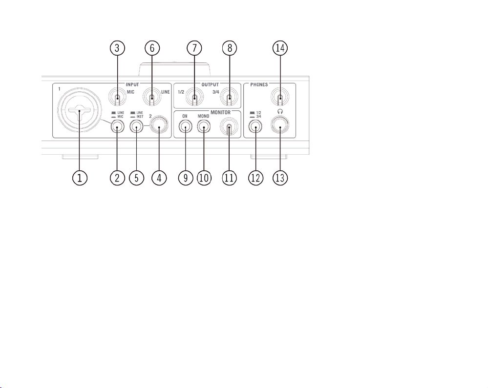
The AUDIO KONTROL 1 Front Panel.
1: Combo Input Jack (Input 1)
This analog audio input accommodates either XLR or phone plugs. The XLR plug
(mono balanced) allows you to connect a microphone, routing the signal through the
mic preamp. The phone plug (¼” jack, TRS mono balanced) allows you to connect
a variety of other line level audio devices (mixer, MIDI sound module etc.).
Please note that, depending on which plug you use (XLR or phone jack); you have
to select the appropriate signal level on the Mic/ Line Switch (2).
When using a condenser microphone, don’t forget to activate the Phantom Power
Switch (18).
AUDIO KONTROL 1 – 10

2: Input 1 Level Switch (Mic/Line)
This switch allows you to select the type of signal you have plugged into Input 1.
If you connect a microphone (using an XLR plug), activate the switch (pushed in).
The incoming signal is then routed to the mic preamp, and its gain can be adjusted
via the Mic Knob (3).
If you connect a line-level device (using a phone plug), deactivate the switch
(pushed out). The incoming signal will then be routed to the line level circuitry and
its gain can be adjusted via the Line Knob (6).
3: Microphone Input Sensitivity Knob (Mic)
This knob allows you to adjust the Input 1 gain if you connect a microphone (XLR
plug). This knob controls the amplication level of the mic preamp.
If you connect a phone jack to Input 1, this knob will have no effect. The level of
your signal can be adjusted via the Line Knob (6).
4: Input Jack (Input 2)
This analog audio input accepts phone plugs (¼” jack, TRS mono balanced). This
input allows you to connect a variety of line-level audio devices (mixer, MIDI sound
module, guitar etc.)
Please note that, depending on what kind of device you connect, you have to select
the appropriate input impedance via the Inst/Line S witch (5).
5: Input Impedance Switch (Inst/Line)
This switch allows you to choose between high and low impedance for Input 2,
depending on what kind of device you have plugged into this input.
If you connect a mixer, a hardware sampler, a MIDI expander or any other line-level
audio device, select the usual low impedance (Line: switch pushed out).
If you connect a guitar or bass (for use with GUITAR RIG 3 LE for instance; see
section 5.3), select high impedance (Inst: switch pushed in).
AUDIO KONTROL 1 – 11

6: Line/Instrument Input Sensitivity Knob (Line)
This knob allows you to adjust the line/instrument input gain. This is relevant to the
signal coming into Input 2, but not exclusively: on Input 1, if Line is selected with
the Mic/Line Switch (2) (and accordingly a phone jack is plugged into Input 1), this
knob will control the level for the incoming signal of Input 1 as well.
The knob also controls the gain of Input 2 if it is set to high impedance, i.e. if the
Input Impedance S witch (5) is active.
To sum up: the Mic Knob (3) only deals with a microphone signal coming into Input
1, and the Line Knob deals with all other signals coming into Inputs 1 and 2.
7, 8: Output Level Knobs (1/2 and 3/4)
These knobs adjust the output volume for each pair of Main Output Jacks on the rear
panel (17).
9: Monitor On/Off Switch (On)
This switch turns the direct monitoring bus on/off. The direct monitoring bus allows you to listen directly to the input signals: the signal on this bus bypasses the
AD and DA converters, the USB processor and the computer, so you can check
what’s coming into the AUDIO KONTROL 1. The monitor signal is mixed with the
computer output on one of the two output pairs (or both if desired). The selection
of the output pair receiving the monitor signal is made within the driver settings
(see section 7.2), and not on the AUDIO KONTROL 1 hardware.
10: Monitor Mono/Stereo Switch (Mono)
This switch, when activated (pushed in), merges the two inputs into one mono signal
for monitoring. This can be useful, for example, if you’re using only one input on
your AUDIO KONTROL 1: you can then monitor this input signal both on the left
and right channels.
AUDIO KONTROL 1 – 12

11: Monitor Level Knob
This knob adjusts the monitor volume when mixed with the computer’s main output
signal. Turned hard left, you will only hear the signal coming from the computer,
i.e. the monitoring signal is muted. Turned hard right, you will hear the input signal
at its original level; the computer’s signal will preserve its level.
12: Headphone Output Selector Switch (1/2 – 3/4)
This switch allows you to choose which output pair (1/2 or 3/4) from the Main Output
Jacks (17) is sent to the headphone output.
13: Headphone Output Jack
This analog audio output accommodates a headphone jack (¼” jack, TRS stereo).
Connecting headphones has no effect on the main outputs.
14: Headphone Output Level Knob
This knob adjusts the volume of the headphone output.
3.1.2. Rear Panel
The AUDIO KONTROL 1 rear panel is equipped with the connections that you won’t
necessarily change for each new project. These include the main audio outputs, the
MIDI input/output and the USB2 connection. It includes also the phantom power
switch for the microphone input.
AUDIO KONTROL 1 – 13
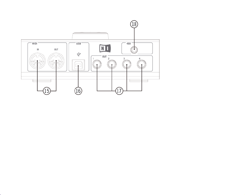
The AUDIO KONTROL 1 Rear Panel.
15: MIDI In/Out Connectors
These connectors allow you to connect MIDI devices to your computer and to
send/receive MIDI messages.
16: USB2 Connector
Use this connector to connect the AUDIO KONTROL 1 to your computer.
17: Main Outputs Jacks (1 to 4)
These analog audio outputs accept phone plugs (¼” jack, TRS mono balanced).
You can use them to send the output signals to an amplication system or other
mix down device (desk, effects…)
AUDIO KONTROL 1 – 14

18: Phantom Power Switch (48V)
This switch has to be activated (pushed in) if you are using a microphone on Input
1 that requires a phantom power supply (e.g. a condenser microphone).
3.1.3. Top Panel
Whe rea s the front and rear panel deal with audio and MIDI signals, the
AUDIO KONTROL 1 top panel is dedicated to the manual controls. It provides you
with a set of four Controllers which act like a remote control for your computer
applications. These Controllers are of two types: the Controller Knob and the Left,
Middle and Right Buttons.
The top panel also provides a number of LEDs for monitoring the various activities
of the box.
AUDIO KONTROL 1 – 15
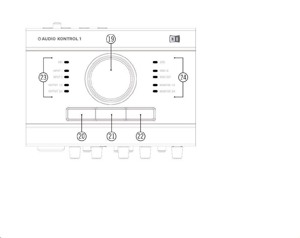
The AUDIO KONTROL 1 Top Panel.
AUDIO KONTROL 1 – 16

19: Controller Knob, 20: Left Button, 21: Middle Button, 22: Right Button
The use of these four Controllers will be extensively explained in the next sections.
They are the core of the remote control of AUDIO KONTROL 1.
23, 24: Info LEDs
These LEDs inform you about various aspects of AUDIO KONTROL 1.
48V: indicates the state of the Phantom Power Switch (18).
►
Input 1: indicates activity at the hardware’s rst audio input. It lights red if the
►
signal is clipped. In this case you should decrease the Input 1 level.
Input 2: indicates activity at the hardware’s second audio input. It lights red if
►
the signal is clipped. In this case you should decrease the Input 2 level.
Output 1/2: indicates activity at the hardware’s rst audio output pair (Main Output
►
Jacks 1/2, 17).
Output 3/4: indicates activity at the hardware’s second audio output pair (Main
►
Output Jacks 3/4, 17).
USB: indicates the USB connection state. If the connection is established it is
►
steadily lit. It blinks while the components are initializing.
MIDI In: indicates if there are MIDI messages being received at the hardware’s
►
MIDI Input (15).
MIDI Out: indicates if there are MIDI messages being sent from the hardware’s
►
MIDI Output (15).
Monitor 1/2: indicates if the direct monitoring signal is being sent to the rst
►
audio output pair (Main Output Jacks 1/2, (17)).
Monitor 3/4: indicates if the direct monitoring signal is being sent to the second
►
audio output pair (Main Output Jacks 3/4, (17)).
AUDIO KONTROL 1 – 17

3.2. Software
The software section of AUDIO KONTROL 1 is divided into two programs:
The Driver, which handles communication between the AUDIO KONTROL 1
►
hardware and your computer.
The M apping Application, which waits for events at the hardware’s top panel
►
elements, reported by the driver, and maps them to software actions.
3.2.1. Driver
The driver basically acts like any other driver supporting a device connected to
your computer. It is an interface between your computer and the real world (in our
case, the AUDIO KONTROL 1 hardware). The AUDIO KONTROL 1 driver handles
different types of signals: audio signals are routed to your computer’s corresponding audio driver (ASIO™, Core Audio™…), MIDI signals are routed to your music
applications, and interactions at the hardware’s top panel (also called “hardware
events”) are sent to the Mapping Application.
Some of the driver parameters can be edited via the Driver Control Panel. Please
refer to section 7.2 for more info on how to edit the driver’s parameters.
3.2.2. Mapping Application
AUDIO KONTROL 1 lets you control your music applications (or, in fact, any other
application) from the four Controllers on the hardware top panel. These Controllers
are assigned to specic commands in your target application (for example a keyboard shortcut or a MIDI message).
AUDIO KONTROL 1 – 18

The Mapping Application controls the mapping system, which handles the interactions with the four Controllers: the Controller Knob and the Left, Middle and Right
Buttons. The mapping system denes the connections between hardware and
software interactions.
Let’s look at a quick example to understand the remote control signal ow in
AUDIO KONTROL 1. When you turn the Controller Knob on the AUDIO KONTROL 1
top panel, the device sends an event through the USB2 connection to your computer. The driver receives this event, translates it and sends it to the Mapping
Application. The Mapping Application then executes the software action corresponding to this event, for instance turning Winamp®’s volume up or down.
Each Button has a special mode called Modier. In this mode, the Button plays
the role of a “Shift” or “Ctrl” key: it does not carry out a specic action in the
target software, but instead, when pressed, it modies the action of the three other
Controllers (the Controller Knob and the two other Buttons) in the target software.
That way, it is possible to dene different assignments for the same Controller,
depending if another Button, set as modier, is pressed or not. This creates different “Layers” in the mapping system: one Main Layer when no modier is pressed,
and three additional Layers, one for each Button (if it is set as a modier). You will
get more info on this in section 7.3.
AUDIO KONTROL 1 – 19
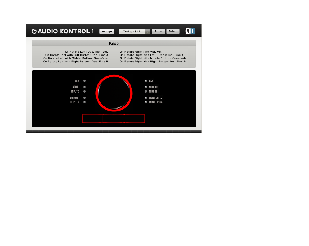
The Mapping Application (Display View).
The mapping system is fully customizable: with the Mapping Application, you can
assign a wealth of actions to each Controller and even to combinations of them,
thus deciding what has to be done in your music application, whatever you do on
the hardware top panel.
A full set of assignments for the four Controllers is called a Page. The Mapping
Application comes with many prepared Pages. These Pages are meant for the most
common uses of the Controllers with NATIVE INSTRUMENTS products, major
sequencers and other audio applications. You can then customize these Pages and
create your own Pages from scratch to t your needs.
For more info on customizing the Mapping Application, please refer to section 7.4.
You will also nd examples of using the Mapping Application in sections 5 and 6.
AUDIO KONTROL 1 – 20

4. Setup
4.1. Hardware
Do not connect the AUDIO KONTROL 1 hardware to your computer until
you have nished the software installation and driver setup (see below,
section 4.2). The driver installer will ask you to connect the Controller at
the proper time.
This sectio n quickly des crib es in a pictorial way some pos sibl e uses of
AUDIO KONTROL 1 in various setups. We give here only general guidelines, the
details to these situations can be found in the sections 5 and 6. Please also note
that you can nd detailed information about each part of the hardware within
section 3.1 above.
In all setups, please use balanced cables as the audio inputs and outputs of your
AUDIO KONTROL 1 hardware are balanced, too.
AUDIO KONTROL 1 – 21
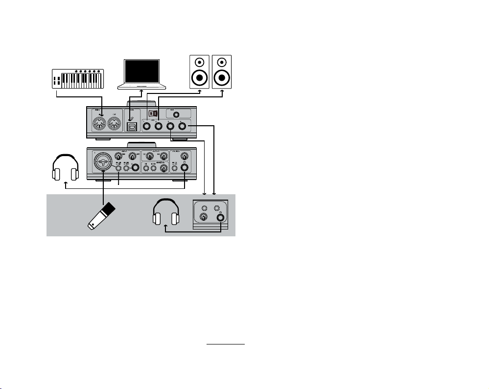
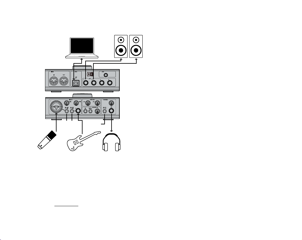
4.1.1. Setup 1: Keyboard/Studio
KEYBOARD / STUDIO
GUITAR
RECORDING ROOM
HEADPHONE AMPLIFIER
CONTROL ROOM
Line/Mic Switch set to Mic
1/2-3/4
Switch
set to 1/2
Line/Inst
Switch
set to Inst
Line/Mic
Switch
set to Mic
This setup shows you how to use AUDIO KONTROL 1 in a studio conguration.
This features:
►
►
This setup serves as a basis for the Use Case of section 6.1, where it is explained
in detail.
All what is needed to record a voice, i.e. a microphone is used with Input 1,
and there are two different signals for the control room (headphones, active
speakers) and the recording room (headphones).
A small MIDI setup, i.e. master keyboard is connected to the MIDI In port of
AUDIO KONTROL 1.
AUDIO KONTROL 1 – 22
DJ - INTERNAL MIXER
1/2-3/4 Switch
set to 1/2
RECORDING ROOM
HEADPHONE AMPLIFIER
CONTROL ROOM
Line/Mic Switch set to Mic
1/2-3/4
Switch
set to 1/2
Line/Inst
Switch
set to Inst
Line/Mic
Switch
set to Mic
DJ - EXTERNAL MIXER
LINE 1 R
LINE 1 L
LINE 2 R
LINE 2 L
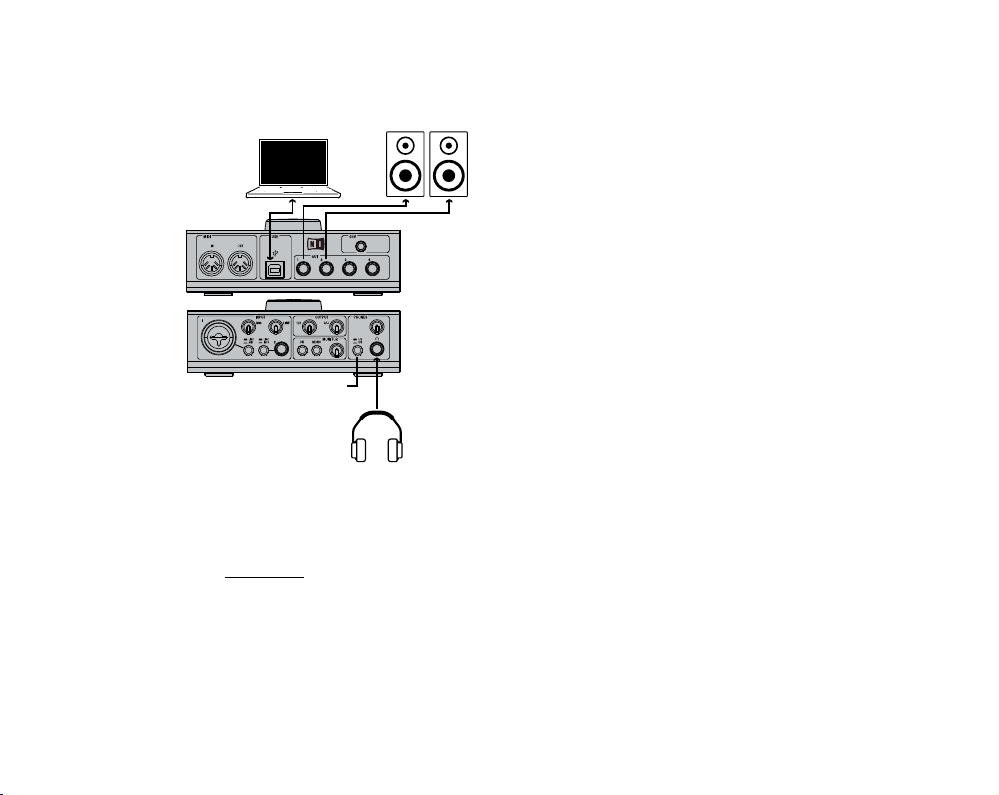
4.1.2. Setup 2: DJing (Internal Mixer)
This setup can be used with the included NATIVE INSTRUMENTS product
TRAKTOR 3 LE. It allows you to execute sophisticated mixes using only a computer,
AUDIO KONTROL 1, a headphone and an amplication system. This setup is used
in the Quickstart of section 5.2 where you will nd detailed information.
AUDIO KONTROL 1 – 23
1/2-3/4
Switch
set to 1/2
Line/Inst
Switch
set to Inst
Line/Mic
Switch
set to Mic
LINE 1 R
LINE 1 L
LINE 2 R
LINE 2 L
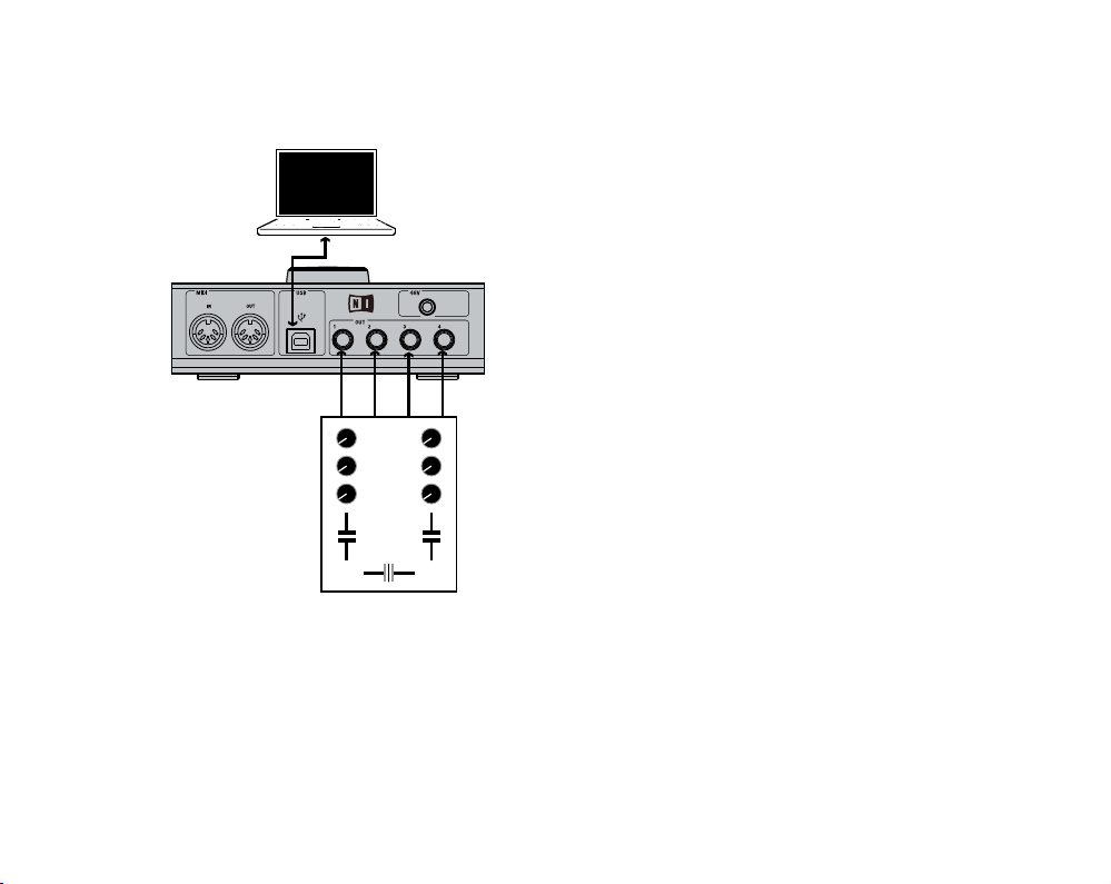
4.1.3. Setup 3: DJing (External Mixer)
If you prefer to use your hardware mixer for DJing with your computer, this setup is
for you. All connections between your mixer and other gear (headphones, amplication system…) are those of a standard DJ setup. The only difference is that your
mixer gets its inputs from AUDIO KONTROL 1 instead of turntables. TRAKTOR 3 LE
can also handle this setup. Please refer to the separate manual of TRAKTOR 3 LE
for detailed information.
AUDIO KONTROL 1 – 24
4.1.4. Setup 4: Guitar/Bass
1/2-3/4
Switch
set to 1/2
Line/Inst
Switch
set to Inst
Line/Mic
Switch
set to Mic
The AUDIO KONTROL 1 software bundle includes the great GUITAR RIG 3 LE,
putting a selection of great guitar amps and guitar-specic effects into your computer. This setup shows you how to play them from your electric guitar. You can
use a microphone at the same time. Therefore, the instrument is connected to
Input 2 with the Line/Inst Switch set to Inst, and the microphone is connected to
Input 1, setting the Mic/Line switch to Mic. This setup is explained in detail in the
Quickstart of section 5.3.
AUDIO KONTROL 1 – 25

4.2. AUDIO KONTROL 1 Software Installation
AUDIO KONTROL 1 is a tightly integrated system of software and hardware: Before
using AUDIO KONTROL 1, the product’s software must be installed, particularly the driver. You might also want to install the bundled software applications
KORE PLAYER, TRAKTOR 3 LE, GUITAR RIG 3LE and Cubase® LE.
Do not connect the AUDIO KONTROL 1 hardware to your computer until
you have nished the software installation and driver setup (see below). The
driver installer will ask you to connect the Controller at the proper time.
To start the installation, insert the AUDIO KONTROL 1 CD into the optical drive.
Open the Windows® Explorer (the Finder on the Mac®) and double -click the
CD to see the les on the CD -ROM. Start the installation by double -clicking
“AUDIO KONTROL 1 Setup” (by launching “AUDIO KONTROL 1 Installer” on
Mac OS® X).
This will sta rt the in stalla tio n p rogram. It will ask which par ts of the
AUDIO KONTROL 1 software you want to install:
AUDIO KONTROL 1 Driver
►
AUDIO KONTROL 1 Mapping Application
►
Service Center
►
Make sure that you install the AUD IO KONTRO L 1 Drive r and the
AUDIO KONTROL 1 Mapping Application when you install the product on
your machine for the rst time. Without them, AUDIO KONTROL 1 will not
work correctly.
AUDIO KONTROL 1 – 26

If you choose to install only a selection of the possible packages, you can start the
installer again at some other time to add the missing packages conveniently. Don‘t
install one of the packages a second time if it is already present on your system:
This might cause problems with your computer system‘s setup.
If you choose to install GUITAR RIG 3 LE, KORE PLAYER or TRAKTOR 3
LE, make sure that the Service Center is also installed. This small applica-
tion is required to activate those products via the internet. You can nd
detailed information about activation in the separate Setup Guide, placed
within the Start menu entry of the Service Center (in the Service Center’s
application folder on Mac OS® X) after installation. If you already installed
the Service Center as part of another product by NATIVE INSTRUMENTS,
a second installation is not necessary.
After you conrmed your selection of packages by going to the next page of the
installer, the software is being installed. This is done by several smaller installers
that are triggered by the main setup program. During the installation you will be
asked a series of questions regarding where certain components of the program
should be placed. In most cases you can simply accept the default choices for each
of these (unless you have some reason for changing them).
The installation process of the AUDIO KONTROL 1 Driver will ask you to
connect your hardware at some point. Please follow the given instructions
closely. However, the installer will also ask you to restar t the computer
when the installation is nished to make the settings become effective.
Don’t do this until all installation processes you selected have been nished
completely!
AUDIO KONTROL 1 – 27

After the installation of all selected packages is completed and the computer has
been re-booted you can start using AUDIO KONTROL 1 by connecting it to your
audio environment. However, there are ve steps that are recommended to do
before you begin to make music:
Continue reading this manual. It explains how you can benet from all features
►
of AUDIO KONTROL 1.
Read the manuals of the bundled software products, i.e. TRAKTOR 3 LE,
►
GUITAR RIG LE, KORE PLAYER and Cubase® LE. If you installed those pa-
ckages, you’ll nd the manuals within the corresponding Start Menu entries
(in the application’s folders on Mac OS® X).
Check the settings of the AUDIO KONTROL 1 Driver. The detailed description
►
of the Driver Control Panel can be found in section 7.2. Once the driver is installed, you can access the settings as follows:
Within the Mapping Application, click on the Driver Button at the top right of the
►
window.
From the Mac OS® X operating system, adjust the audio settings within the
►
System Preferences.
From the Windows® operating system, use the “Control Panel” link within the
►
Start menu created during the driver installation.
Co nfi gure the bundle d sof tw are by NATIV E INST RUMENT S to u se
►
AUDIO KONTROL 1 as audio and MIDI interface. This is described in the separate Setup Guide installed with the Service Center. You can also refer to the
quickstarts of this manual (found in section 5) for a fast approach.
Congure any third-party software you intend to use with AUDIO KONTROL 1,
►
e.g. your operating system, your sequencer, or programs like Winamp® and
iTunes®. Refer to the documentation of that software for detailed information
on how to set it up correctly. The following section will also give you a fast
introduction.
AUDIO KONTROL 1 – 28

Important: You can install the additional software bundle by using the seperate installers on the installation disc.
4.3. Conguring Third-Party Software
4.3.1. The MIDI ports of AUDIO KONTROL 1
AUDIO KONTROL 1 contains one MIDI input port and one MIDI output port on the
hardware side. However, when you congure your software applications to interact
with the AUDIO KONTROL 1 hardware, you will note that the driver offers a second
MIDI input/output pair.
The rst MIDI pair can be used to access the hardware ports. Activate them if you
want to control your software with external MIDI gear (e.g. a master keyboard) or
if you want to send MIDI messages to any other hardware.
The second pair is obviously not present at the hardware. Instead, it is used by
the Mapping Application to send MIDI messages to your applications. Only if your
application uses this second pair of MIDI ports, the Mapping Application will be
able to control it via MIDI.
Of course, you can combine both ports, i.e. your application can use the external
MIDI input and the virtual input at the same time.
AUDIO KONTROL 1 – 29

4.3.2. Using AUDIO K ONTROL 1 as the default audio interface in Windows® XP
To use AUDIO KONTROL 1 as your default audio interface under Windows® XP,
do the following:
Open Start > Control Panel > Sounds and Audio Devices.
►
Click the Audio tab.
►
In the Sound playback, Sound recording and MIDI music playback sections,
►
click the Default device menu and s elect AUDIO KONTROL 1 Ou t 1,
AUDIO KONTROL 1 In 1 and AUDIO KONTROL 1 MIDI Out 1 respectively.
Click OK to close the Sounds and Audio Devices dialog.
►
4.3.3. Using AUDIO KONTROL 1 as the default audio interface in Mac OS® X
To use AUDIO KONTROL 1 as your default audio interface under Mac OS® X, do
the following:
From the Apple® menu, select System Preferences, and in the panel that
►
opens, click Sound.
Click the Sound Effects tab and choose AUDIO KONTROL 1 in the Play alerts
►
and sound effects through menu.
Click the Output tab, and choose AUDIO KONTROL 1 in the Choose a device
►
for sound output list.
Click the Input tab, and choose AUDIO KONTROL 1 in the Choose a device for
►
sound input list.
AUDIO KONTROL 1 – 30

4.3.4. Conguring Cubase® or Cubase® LE with AUDIO KONTROL 1
(ASIO™)
To congure Cubase® or Cubase® LE with AUDIO KONTROL 1, do the following:
From the Devices menu, select Device Setup. The Device Setup dialog pops
►
up.
In the Devices list, on the left, click VST Audiobay.
►
Select the AUDIO KONTROL 1 driver from the Master ASIO™ Driver menu.
►
The procedure is similar in all applications that use ASIO™ to connect to your
audio interface. For detailed explanations, please refer to the respective operation
manual.
4.3.5. Conguring Logic® with AUDIO KONTROL 1 (Core Audio™)
To congure Logic® 7 Pro with AUDIO KONTROL 1, do the following:
From the Audio menu, select Audio Hardware & Drivers. The Preferences dia-
►
log automatically shows the Audio/Drivers/Core Audio™ tab.
Select the AUDIO KONTROL 1 driver from the Driver menu.
►
The procedure is similar in all applications that use Core Audio™ to connect
to your audio interface. For detailed explanations, please refer to the respective
operation manual.
AUDIO KONTROL 1 – 31

5. Quickstarts
At this point, we assume that you have already physically connected your MIDI keyboard to your computer, either via USB or utlizing the AUDIO KONTROL 1’s MIDI-In
port. We also assume that you have set up your keyboard as a MIDI input device
in your operating system, so that it is available to applications using MIDI. If not,
do so before you proceed. For more information about connecting MIDI devices to
the AUDIO KONTROL 1’s MIDI ports, please read chapter 4.3.1 of this manual. If
you want to connect your MIDI keyboard directly to your computer via USB, which
is the most common method for modern keyboards, refer to the manual that came
with your MIDI keyboard.
So much for the physical part. In addition, the Mapping Application should be
running, as it loads automatically when the system starts. If this is not the case,
please refer to section 4.2 for more information. You should also have already
installed the software bundle included in AUDIO KONTROL 1. Once again, if not,
please refer to section 4.2.
Also, please make sure that you have carefully read section 3.1, which describes and
explains every socket and control found on the AUDIO KONTROL 1 hardware.
In the following you will learn how use the AUDIO KONTROL 1 for remotely controlling the applications delivered alongside the AUDIO KONTROL 1 software.
For more complex setups and advanced uses of AUDIO KONTROL 1, please read
the following chapter 6.
AUDIO KONTROL 1 – 32

5.1. Controlling KORE PLAYER
Included on the AUDIO KONTROL 1 installation DVD -ROM is KORE PL AYER, a
software instrument loaded with a variety of high-class sounds instantly playable
from your MIDI keyboard. In the following sections you will learn how to set up
KORE PLAYER’s MIDI connections and how to control KORE PLAYER utilizing the
AUDIO KONTROL 1’s Knob and Buttons.
For general information about KORE PLAYER, please refer to the dedicated manual
you can nd in the KORE PLAYER installation folder on your computer's hard disk.
In the following we will use some terms that refer to certain elements and functionalities available in KORE PLAYER. If all these terms are completeley new to you, we
suggest that you have a look at the KORE PLAYER manual rst to learn more about
KORE PLAYER’s basic concepts and the elements of the user interface.
Besides being able to receive MIDI notes from a keyboard, KORE PLAYER can
also utilize MIDI Continuous Controller information (shortened MIDI CC). As the
AUDIO KONTROL 1 can send such information, you can use it to conveniently
access parameters in KORE PLAYER from the AUDIO KONTROL 1’s Knob and
Buttons.
AUDIO KONTROL 1 – 33

Before you can use AUDIO KONTROL 1 to control KORE PLAYER, you need to select its entry from the
Input Menu.
To make a MIDI device available within KORE PLAYER, do the following:
Start KORE PLAYER.
►
In KORE PLAYER, load a KoreSound® by dragging it from the Search Results List
►
onto the Global Controller.
From KORE PLAYER’s File menu, select the “Audio and MIDI Settings” entry. A
►
dialog regarding KORE PLAYER’s audio and MIDI connections will open.
In the Audio and MIDI Settings dialog, click the MIDI Tab to select the MIDI Page
►
and show the available MIDI devices and their respective status.
On the MIDI Page, the MIDI-In Devices List displays all MIDI input devices installed
►
on your computer. In the list, find the MIDI devices you want to use with
KORE PLAYER. Check if the status entry in the eld right to each device’s name
reads “On”, which indicates that the device is active in KORE PLAYER. If the devices
you want to use are not active (“On”), click their status entries to activate them.
AUDIO KONTROL 1 – 34

When you have activated all desired MIDI devices, close the Audio and MIDI
►
Settings dialog and continue within KORE PLAYER:
In KORE PLAYER, click the Control Tab to display the internal MIDI Menu.
►
From the Input Menu, select the “Audio Kontrol 1 Virtual MIDI In” entry.
►
You have just selected the AUDIO KONTROL 1 as the MIDI remote control device for
KORE PLAYER. Now there’s only one thing left to do: you need to tell KORE PLAYER
which of its actions you want to control from the AUDIO KONTROL 1. The easiest
way to do this is by selecting a pre-assigned Controller Page, as described in the
following section.
Four control elements are located on the AUDIO KONTROL 1 top panel; their
behavior is managed by the Mapping Application. The mapping system for the
hardware’s four top panel Controllers is organized into the so- called Controller
Pages. A single Controller Page is a full set of assignments for the four Controllers
in the four Layer s.
If this sounds new to you, we recommend you to read the relevant subsections in
section 2. The concept of Layers is extensively described in section 7.3 of this
manual.
AUDIO KONTROL 1 comes with plenty of Factor y Pages for many applications, and
there is also one for KORE PLAYER. In order to make the AUDIO KONTROL 1’s
remote control capabilities available in KORE PLAYER, you need to load the ap-
propriate Controller Page rst. To get you started immediatly, we have prepared
a Controller Page for the AUDIO KONTROL 1’s Mapping Application that lets you
manipulate the sound loaded in KORE PLAYER very effectively:
The AUDIO KONTROL 1's Left Button switches KORE PLAYER’s Parameter
►
Button 1 (the leftmost button in the upper row) on and off.
The Middle Button does the same as above for Parameter Button 2 (which is
►
the button right beside Parameter Button 1).
AUDIO KONTROL 1 – 35

Turning the AUDIO KONTROL 1’s Knob will move the Sound Variation Morph
►
across the Sound Variation Grid in a horizontal direction, starting with Sound
Variation 1 in the upper left corner. To get the most out of KORE PLAYER’s
innovative Morphing feature, it makes sense to assign the AUDIO KONTROL 1’s
Knob to this function.
The Right Button works as a Modier: Pressing this button toggles the assig-
►
nments made to the other controls to a second layer of assignments. If you
hold down the Right Button while turning the Knob, you can move the Sound
Variation Morph vertically and thus reach the Sound Variations in the lower row.
If you hold down the Right Button and press the Left Button or the Middle
Button, this will change the state of KORE PLAYER’s Parameter Buttons 5 or
6, respectively.
To load the KORE PLAYER Controller Page for AUDIO KONTROL 1, do the following:
Bring the Mapping Application to the front in your operating system: double-
►
click the application’s icon within the Windows® XP system tray (or the Finder's
menu bar on Mac OS® X, respectively). If the icon is not present there, the
application is not running. In this case, start it from the Windows® Start menu
(or the application’s folder on Mac OS® X).
In the Mapping Application, the leftmost button in the top row of controls
►
either reads “Assign” or “Display”. If you see “Display”, click on it to switch to the
Display View. If you see “Assign”, then leave it, as you are already where we need
to be: in the Display View.
The menu in the top row is called the Page Select Menu. Click on it to select the
►
appropriate Controller Page to control KORE PLAYER. Select the entry “NI Kore
Player”. The Mapping Application then loads this Page and you will see all of
its assignments in the rest of the window.
AUDIO KONTROL 1 – 36

The Mapping Application with the KORE PLAYER Page loaded.
You are now able to control KORE PLAYER as described above. To check if everything works as intended, play and hold some notes on your MIDI keyboard and press
the AUDIO KONTROL 1’s Left Button. The leftmost upper Parameter Button in
KORE PLAYER should reect this action and change its state each time you press
the Left Button. Now turn the AUDIO KONTROL 1’s Knob while you play some notes
and listen how the sound changes as the Sound Variation Morph moves across the
Sound Variation Grid. Press the Right Button to move the Sound Variation Morph
vertically and access the lower row of Sound Variations.
The lower part of the Mapping Application window, called the Hardware Area, represents the hardware’s top panel. When you move your mouse above one of the displayed Controllers, the upper part of the window, called the Information Area, displays
the assignments for that Controller. We will get back to these areas later on.
AUDIO KONTROL 1 – 37

5.2. Controlling TRAKTOR 3 LE
Now let’s take control of TRAKTOR 3 LE. To see what’s happening, bring
TRAKTOR 3 LE to the front. Move the Controller Knob on your hardware: the
Master Knob in the Mixer instantaneously follows the Controller Knob movements,
adjusting the overall output volume of your mix.
If you press any of the three Buttons, nothing happens: they are all set to the
Modier mode, meaning that they don’t have a specic action, but instead they
modify the action of each Controller.
For example, press and hold the Left Button. You are now controlling Deck A. The
Controller Knob doesn’t control the Master Volume anymore, but instead it drives
the Fine Pitch parameter for that Deck. This parameter is not actually displayed on
the TRAKTOR 3 LE interface; it can only be controlled via MIDI – and now via
AUDIO KONTROL 1. Like it says, this parameter is a ne pitch adjustment, much
more precise than the Tempo Knob that you see on each Deck.
With the Left Button still held down, the Middle and Right But tons are the Play and
Cue Bu ttons for Deck A, respectively. There’s no need to grab the mouse to start,
stop and cue the playback anymore, you just have to press and hold the Left
Button, and then play with the two other Buttons. Easy, isn’t it? That’s exactly what
AUDIO KONTROL 1’s Remote Control is about.
Now that you’ve nished with the Left Button, release it and press and hold the Right
Button. You now have access to exactly the same features, but for Deck B. Fine Pitch,
Play and Cue for Deck B are on your hardware’s top panel, right at your ngertips.
Up to now, we've played with the Main Layer (no Button pressed and held), and
the Left and Right Layers (Left or Right Button pressed and held, respectively). The
last Layer, the Middle Layer, is logically activated by pressing the Middle Button. You
then have access to the following parameters: the Controller Knob controls the
Crossfader, and the Left and Right Buttons control the rst and second buttons of
the Master Effect currently loaded in TRAKTOR 3 LE.
AUDIO KONTROL 1 – 38

With four Controllers on your hardware’s top panel, you have thus control over 10 parameters in your software. Load another Factory Page dedicated to TRAKTOR 3 LE,
or create a custom User Page, and you’ll get another 10 parameters on your
AUDIO KONTROL 1 hardware top panel.
You will learn how to program your own Controller Pages in sections 6.2 and 6.3,
and you can nd all info about it in section 7.4.4.
5.3. Controlling GUITAR RIG LE
We will now move to another musical world: the electric guitar and bass empire.
Following the multi-functional concept driving AUDIO KONTROL 1, we included
the GUITAR RIG 3 LE software. Equipped with some of the best amps and effects
from the award-winning GUITAR RIG 3 software, GUITAR RIG 3 LE puts a world
of studio-quality guitar and bass sounds at your ngertips.
AUDIO KONTROL 1 – 39

With GUITAR RIG LE, you can take your favorite guitar gear with you wherever you go.
Such a setup utilizing a computer and software has some serious advantages if
compared to a guitar directly plugged into an amplier: it’s really easy to take all
your favorite amps and effects with you in a laptop bag.
Now let’s set all this up. We will follow the guidelines provided by the picture in
section 4.1.4.
AUDIO KONTROL 1 – 40

5.3.1. Audio Connections
In order to listen to what you are playing on your instrument on your speakers or
headphones, you need to follow these steps:
Turn all relevant signal levels down: on your instrument, and on the Line Input
►
Sensitivity Knob (labeled Line) of your AUDIO KONTROL 1 hardware.
Plug your guitar (or bass) into AUDIO KONTROL 1’s audio interface instrument
►
input.
Plug the jack coming from your instrument into Input 2’s Jack. Because the
►
guitar and the bass are high impedance equipment, you must activate the high
impedance circuitry by engaging the Input Impedance Switch (Inst/Line, position Inst).
Adjust the input level: strum some strings on your guitar and slowly turn the
►
Line Input Sensitivity Knob on the hardware front panel clockwise while carefully
looking at the Input 2 LED on the hardware top panel. The Input 2 LED gives you
an idea of the incoming signal level at this input: If there is no signal present
at this input, the LED is off. If there is an incoming signal at an acceptable
level, the LED lights green. If the incoming signal level is too high, the LED
turns red. What we want is to have the LED light green and never turn red. To
achieve this, strum the loudest part that you plan to play on your guitar, and
look at the LED: if it is always green, turn the Line Input Sensitivity Knob up,
until the LED starts turning red. At that point, turn the Knob slightly down,
until the LED is no longer red. Now your signal is at the optimum level, giving
you the highest dynamic range without clipping.
Now that you have set up the input section, let’s have a look at the outputs. At
rst, make sure that the Output Level Knob 1/2 is fully turned down, as well as the
volume control on your amplier. As an example, we will use the rst two outputs
on AUDIO KONTROL 1’s rear panel, as depicted in section 4.1.4. If you did not
do it yet, connect the Main Output Jacks 1 and 2 on the hardware’s rear panel to
your power amplication system.
AUDIO KONTROL 1 – 41

5.3.2 Conguring GUITAR RIG 3 LE
As with KORE PLAYER, TRAKTOR 3 LE and any other music application, we have
to quickly check the audio setup in the software.
From GUITAR RIG LE’s File menu, select the “Audio and MIDI Settings” ent-
►
ry.
In the dialog that opens, click on the Soundcard Tab.
►
On the Soundcard Page, check that the selected Output Device is “ASIO™
►
AUDIO KONTROL 1”.
Click on the Routing Tab. In the Inpu ts Tab, connect GUITAR RIG LE’s inputs
►
to AUDIO KONTROL 1’s inputs (actually only Input 2, in our case). In the
Outputs Tab, conne ct the outputs to those physical outputs used on the
AUDIO KONTROL 1’s hardware (in our case Outputs 1 and 2).
The Audio is now ready-to-use. You can turn all relevant levels up again (but don’t
touch the Line Input Sensitivity Knob!).
Note: If you look after your neighbor’s and housemates nerves, you can use head-
phones instead of an amplication system:
Turn the Output 1/2 Level Knob all the way down to make sure you don’t ac-
►
cidentally blast your neighbors with high volume.
Connect your headphones to the Headphone Output Jack.
►
Disengage the Headphone Output Selector Switch so that it monitors the Main
►
Outputs 1 and 2 (as we used those in our setup).
Carefully turn the Headphone Output Level Knob up. But remember: Using
►
headphones at high levels and/or for a long time can be very dangerous for your
ears!
AUDIO KONTROL 1 – 42

5.3.3. Controlling GUITAR RIG 3 LE
In order to control parameters within GUITAR RIG 3 from the AUDIO KONTROL 1’s
control elements, you need to “connect” GUITAR RIG 3 LE to the Mapping
Applications. This way, GUITAR RIG 3 LE can receive the MIDI messages coming
from the Mapping Application. To establish a connection between GUITAR RIG 3 LE
and the Mapping Application, follow these steps:
As with setting up the audio connections, open the “Audio and MIDI Settings”
►
from GUITAR RIG 3 LE’s File menu.
Select the MIDI Tab and activate both input ports of AUDIO KONTROL 1 by
►
clicking their “Off” labels. If the labels already read “On” for both inputs, you
don’t need to change the options.
Click “OK” to close the dialog box.
►
Now you need to select the NI AUDIO KONTROL 1 Control Page that is copied to
your hard disk during the Guitar Rig 3 LE installation procedure. Navigate to the
Options inside GUITAR RIG 3 LE’s Sidekick and enter the Controller Assignments
section. You can choose the template as shown in the Screenshot below. Please
refer to the GUITAR RIG 3 manual to learn all about GUITAR RIG 3 LE.
AUDIO KONTROL 1 – 43

If you hover the mouse cursor over a Knob or Button, the Information Area displays the current assignments of the respective control.
Bring the Mapping Application to the front in your operating system. In the top
Application Control Bar, the rst Button is labeled either „Assign” or “Display”.
If you see “Display”, click on it to switch to the Display View. If you see “Assign”,
then leave it, as you are already where we need to be: in the Display View.
On the right, click on the Page Select menu and select, the entry “NI Guitar Rig
3”. The Mapping Application automatically loads that Page and you will see all its
assignments in the rest of the window.
AUDIO KONTROL 1 – 44

The Mapping Application with the “NI Guitar Rig 3” Page loaded.
The lower part of the window, called the Hardware Area, represents the hardware’s
top panel. When you move your mouse above one of the displayed Controllers, the
upper part of the window, called the Information Area, displays the assignments
for that Controller.
As shown on the Mapping Application, this Page is quite simple. It implements
only four controls, corresponding to the following GUITAR RIG 3 LE parameters,
now accessible from the hardware’s top panel:
Let’s play now with the AUDIO KONTROL 1 hardware top panel:
The Controller Knob drives the Output Volume.
►
The Left Button loads the previous preset of the current soundbank.
►
AUDIO KONTROL 1 – 45

The Middle Button toggles the fullscreen mode of GUITAR RIG 3 LE on and
►
off.
The Right Button loads the next preset of the current soundbank.
►
If you want to have other controls on the hardware’s top panel, feel free to create
your own set(s) of assignments as described in sections 6.2, 6.3 and 7.4.4.
5.4. Remote Controlling Winamp®/iTunes®
This last situation deals with an every-day computer task, actually much more
common than playing a guitar or DJing in a club. It is just about listening to music.
For that, AUDIO KONTROL 1 will take control of your favorite audio player and
bring its main commands right to your nger tips. We assume here that you are
using Winamp® on your PC or iTunes® on your Mac®. Of course, if you are using
another audio player, you can create one or several User Page(s) to control it from
AUDIO KONTROL 1’s hardware top panel.
Here we don’t have to make any particular audio connections but the usual ones be-
tween a computer and a hi- or amplication system. We will describe them quickly,
assuming that you have already read the previous quickstarts. After all, it’s only the
fourth time that we’ve connected AUDIO KONTROL 1’s outputs to an amplication
system… If anything is unclear, please refer to the previous quickstarts.
Turn all relevant volume controls down.
►
Connect the Main Output Jacks 1 and 2 to your amplication system.
►
Plug headphones into the Headphone Output Jack if desired.
►
Turn all relevant volume controls up to a reasonable level.
►
AUDIO KONTROL 1 – 46

That was it on the hardware side. On the software side, the operating system needs
to use the AUDIO KONTROL 1 as its default interface, as Winamp® and iTunes®
are simply relying on the operating system’s settings. The necessary steps to set
up AUDIO KONTROL 1 as your default audio interface are described in sections
4.3.2 (Windows®) and 4.3.3 (Mac®).
Now we want to load the right Controller Page:
Bring the Mapping Application to the front in your operating system.
►
In the Page Select Menu, choose “Winamp” (Mac®: “iTunes”).
►
That’s all; everything is now set up to control your audio player from the
AUDIO KONTROL 1 hardware top panel.
From now on, you will have the following controls via the Controller Knob and the
three Buttons.
With no Button pres sed:
The Controller Knob controls the volume.
►
The Left Button doesn’t do anything (see below).
►
The Middle Button is the Start Button.
►
The Right Button is the Pause/Continue Button.
►
With the Left Button pressed:
The Controller Knob can be used to rewind or forward the current track.
►
The Middle Button switches to the previous track in your playlist.
►
The Right Button switches to the next track in your playlist.
►
After a few minutes, you will nd that the Remote Control is much more efcient
than grabbing your mouse or your keyboard to perform the same actions in the
software, notably because you don’t need to bring the target application to the front
before executing the commands from the AUDIO KONTROL 1 hardware.
As always, you are of course absolutely free to compose other Controller Pages
according to your wishes.
AUDIO KONTROL 1 – 47

These four quickstarts showed you the basics of AUDIO KONTROL 1. But the next
section will explain some more complex situations, in which AUDIO KONTROL 1
can considerably improve both efciency and quality in your workow.
AUDIO KONTROL 1 – 48

6. Use Cases
We will assume here that you have already read (and understood) the previous sections (Parts of the Product, Setup and Quickstarts). If you are an advanced user,
you don’t necessarily need to have read all these previous sections carefully, but
we think that it’s always a good idea to spend a few minutes on the basics (and if
you are an advanced user, it shouldn’t take you too much time to read). Moreover,
the quickstarts also show you how to start using the AUDIO KONTROL 1’s Remote
Control, and we will start here from that point. If you feel unsure about anything,
don’t hesitate to get back to the previous sections, or to look in the Reference
Section later in this manual.
6.1. Recording Vocals
The rst use case that we will look at is recording a voice. AUDIO KONTROL 1’s audio
interface allows you to make high quality voice recordings, assuming of course that
you have a microphone that is good enough to achieve this… AUDIO KONTROL 1
comes with enough connections to set up an efcient voice-recording conguration. Actually we will implement here something similar to the setup depicted in
the section 4.1.1, but without the MIDI part (master keyboard…).
AUDIO KONTROL 1 – 49

6.1.1. What Is the Situation, And How to Connect Everything
You are sitting comfortably in the control room. The song has already been recorded,
it’s loaded into your favorite multi-track recording software, and only the voice track
is missing. The singer is standing in the recording room. You want to:
record his (her) voice,
►
send the song to his (her) headphones, so that he (she) can sing on it,
►
listen to the result live and direct in your control room, i.e. the song playback
►
and the voice being recorded.
First, we will plug the microphone’s balanced XLR jack into AUDIO KONTROL 1’s
Combo Input Jack.
Depending on the type of microphone you use for your recording, the Phantom Power
Switch needs to be activated. You can nd it on the rear panel of AUDIO KONTROL 1.
Please have a look into your microphone’s documentation if you are not sure
whether to use phantom power or not. Using the incorrect setting might damage
the microphone.
Don’t forget to engage the Input 1 Level Switch, so that the incoming signal goes
through AUDIO KONTROL 1’s microphone pre-amplication circuitry. The input
signal level is adjustable on the hardware side by the Microphone Input Sensitiv ity
Knob. Note that you will probably also have an input level control within your re -
cording software.
As we said, we will here follow the diagram as shown in section 4.1.1. In this diagram, Outputs 1 and 2 are used for monitoring purposes (i.e. they are sent to your
control room amplication system). The control signal being sent to the singer is
coming from Outputs 3 and 4.
So let’s connect your monitoring sys tem to Mai n Out put Jacks 1 and 2 on yo ur
AUDIO KONTROL 1’s hardware rear panel, and the headphone amplier device
to Main Output Jacks 3 and 4.
AUDIO KONTROL 1 – 50

If you wish, you can plug your own headphones into the AUDIO KONTROL 1’s Headphone
Output Jack. As you would expect, the Headphone Output Selector Switch next to it allows
you to switch between your own mix in the recording room, and what the singer
actually hears in his (her) headphones.
That’s the physical connections dealt with. Now we have to congure our recording
software accordingly.
6.1.2. Conguring the Recording Software
General Settings
We will assume here that you have already followed the instructions of the Setup
section and have your AUDIO KONTROL 1 working with your Cubase® LE/Cubase®/
Logic®/Sonar™/… software.
We will be using Steinberg’s Cubase® LE included in AUDIO KONTROL 1 software
bundle. For other recording-capable software, please refer to their operation manuals. The basic recording functions are generally quite similar in all of them.
We want to specify in the recording software that the main mix has to be sent to
AUDIO KONTROL 1’s outputs 3 and 4. To do so, we have to congure the virtual
busses in the recording software.
In Cubase® LE, open the VST Connections window in the Devices menu. There, you
can set up the input busses you need. Check that AUDIO KONTROL 1’s Inputs 1
and 2 are selected for the input bus you are using (you would actually only need
Input 1 if you are recording in mono).
Next, switch to the Outputs tab of the same window. Check that AUDIO KONTROL 1’s
Outputs 1, 2, 3 and 4 are selected for the output busses you are using.
Note: If you wish, you can rename each bus so that you can quickly see in
Cubase® LE’s mixer where each track is going (e.g. “Control Room Left /
Right”, “Input Left/Right”, etc.).
AUDIO KONTROL 1 – 51

Project Settings
We will assume that you already have a running project for this song, with an audio
mix down track or several audio tracks to be played back, on which the singer will
express her (his) talent.
If you have not already done so, open an existing project, or create a new one, in
which you will set up one mono track for the voice being recorded, plus one or
several other audio/MIDI tracks for the playback material. Your main project window
should look more or less like this:
6.1.3. Monitoring Conguration
Monitoring
Monitoring, ie listening to the input signal during recording, can be done in three
different ways:
within your recording software,
►
externally, via the Direct Monitoring facilities on AUDIO KONTROL 1’s hard-
►
ware,
by using ASIO™ Direct Monitoring, which is a mixture of the rst rwo me-
►
thods.
AUDIO KONTROL 1 – 52

Monitoring Through Your Recording Software
When monitoring via your recording software, the input signal is mixed in with the
audio playback. This way, you can adjust the monitoring level/panning of your input
signal from within the Mixer, and you can directly apply EQ and/or effects to the
monitoring signal, just like any other project track. The potential issue with this
type of monitoring is that the monitoring signal will be delayed according to the
input latency value of AUDIO KONTROL 1. Depending on the CPU power of your
system, it might become problematic in some situations.
To enable the voice track monitoring, you need to activate its Monitor bu tton, on the
Mixer, in the main project window or in the track’s Inspector:
Note that Cubase® LE, like many other modern recording-capable types of software,
can handle very complex recording setups with different busses/mixes/settings
covering numerous recording issues. Here we show a very simple example of a
recording setup, as we cannot explain in a few lines what a recording software’s
manual describes in dozens of pages. For an in-depth explanation of what you can
do with your recording software, please refer to its operation manual.
Cubase® LE also provides you with automatic monitoring options. For more info,
please refer again to the Cubase® LE manual.
AUDIO KONTROL 1 – 53

Direct Monitoring through AUDIO KONTROL 1
AUDIO KONTROL 1 provides you with its own monitoring facilities. This solution
has some advantages:
You can control it directly on the hardware.
►
The monitor signal is not affected by any potential latency issue.
►
To activate AUDIO KONTROL 1’s hardware monitoring, follow these steps:
Engage the Monitor On /Off Switch on the hardware’s front panel. On the hardware
►
top panel, one of the two monitoring LEDs (or both) will light up, depending on
your settings in the Mapping Application (see below).
Engage the Monitor Mono/Stereo Switch next to it, so that you can hear the voice
►
on both output channels.
In the Mapping Application you can select to which output the input signal is
►
monitored. Open the main menu’s Monitoring entry: If the singer wants to hear
her (his) voice in the headphones, select 1/2 and 3/4. If the singer does not want
to hear her (his) voice, select 1/2, so that the voice only goes to your monitoring
speakers.
At any time, you can adjust the Monitor Level Knob to control the mix between
►
the music track coming from the computer and the voice coming directly from
Input 1.
AUDIO KONTROL 1 – 54

6.1.4 ASIO™ Direct Monitoring
ASIO™ Direct Monitoring is a combination of the two former methods. The monitoring is done directly in AUDIO KONTROL 1, so that the monitoring signal doesn’t
pass through your recording software (thus avoiding potential latency issues), but
you can still activate the monitoring from within the recording software, also giv-
ing you the benet of its various monitoring modes. Since the monitoring signal
doesn’t go through your recording software, you won’t be able to apply any EQ or
effects to it.
To activate ASIO™ Direct Monitoring, open the Device Setup dialog in the Devices menu
and use the Direct Monitoring checkbox on the VST Audio System page.
To enable the voice track monitoring, you need to activate its Monitor bu tton, on the
Mixer, in the main project window or in the track’s Inspector:
In the Mapping Application’s Monitor menu, you can then select which output the
input signal will be monitored from (see above).
Cubase® LE also provides you with automatic monitoring options. For more info,
please refer to the Cubase® LE manual included as a PDF in the installation
folder.
AUDIO KONTROL 1 – 55

6.1.4. Checking the Levels
First, we have to set the input level on the AUDIO KONTROL 1 audio interface.
This is done via the Microphone Input Sensitivity Knob (labeled “Mic” on the hardware’s
front panel). The goal is to achieve the highest input level possible (in order to
get the highest dynamic range and the lowest noise in your recording), but not so
loud that clipping at the A/D converter occurs. To do this, ask your singer to make
some noise, approximately at the highest level he or she will be singing. Then do
the following:
First, turn the Mic Knob all the way down.
►
Turn it up slowly, so that you see the green LED on the hardware’s top panel
►
comes on, until the LED starts turning red.
At that point, turn the Mic Knob back down slightly, ensuring that the LED never
►
goes red anymore.
Now you’re done; the input level is now set correctly on the hardware side.
►
6.1.5. Recording the Voice
The last thing to do before starting the recording is to enable the corresponding
track for recording. In Cubase® LE, this can be done on the track in main project
window, in the mixer or in the track’s Inspector, by clicking on the Record Enable
button next to the Moni tor but ton (the Record Enable button turns red):
AUDIO KONTROL 1 – 56

You might be able to see the input level in your recording software. In Cubase® LE,
the input level is displayed when the recording is stopped, on the corresponding audio channel, both in the Track List meter and in the mixer strip for that channel.
Now everything is ready, you can start the recording via one of the various methods
described in your recording software operation manual (for example, simply click
on the Record button in the Transport Bar).
One more time, this is a very short presentation of what you can achieve when working with AUDIO KONTROL 1 and any serious recording software. Don’t hesitate to
spend some time in the recording software manual; it will allow you to obtain high
quality recordings in more complex setups.
6.2. Controlling a Sequencer - Creating Assignments
with Key Commands
We will now look at two other cases, in which AUDIO KONTROL 1’s Remote Control
allows you to pilot your music software as you wish.
The rst case deals with a sequencer application. Major sequencers are huge pieces
of software with hundreds of functions. Depending on what you are doing, you often
need only part of these functions. Here we will use AUDIO KONTROL 1’s ability
to reproduce keyboard commands. All major sequencers have endless keyboard
shortcuts assignments, covering numerous software functions. By assigning the
most often used functions to the Remote Control, you can save time by avoiding
the most often repeated mouse and/or keyboard actions.
Naturally, we will use Cubase® LE for this Use Case. Whether you are using this sequencer or another, we recommend you refer to your sequencer’s operation manual
to get all relevant information about the software’s keyboard commands.
AUDIO KONTROL 1 – 57

6.2.1. Factory Page Overview
Loading a Factory Page
We will start with a Factor y Page designed for Cubase® LE.
Bring the Mapping Application to the front in your operating system, and click on the
Page Select menu in the top Application Control Bar. In the menu, select “Cubase LE”.
The Controller Page is loaded and the hardware’s top panel assignments are now
as follows:
With no Button pres sed:
The Controller Knob controls the MIDI Continuous Controller 1.
►
The Middle Button controls the Start/Stop command (shortcut: space bar)
►
The Right Button controls the Record command (shortcut: “*” on the numeric
►
keypad)
With the Left Button pressed:
The Controller Knob still controls the MIDI Continuous Controller 1.
►
The Middle Button now controls the Cycle On/Off commands (shortcut: “/” on
►
the numeric keypad)
The Right Button sets the cursor back to zero (shortcut: “.” on the numeric
►
keypad).
This set of assignments is denitely transport-oriented: from AUDIO KONTROL 1’s
hardware top panel, you have access to all major transport actions in Cubase®
LE. This allows you, for instance, to focus your mouse actions on the mixer or on
the plug-ins.
Analyzing the Assign View
Here we need to take a closer look at these mappings, in order to understand how
they actually work. Bring the Mapping Application to the front, and switch to the Assign
View: if you see an Assign Button in the top Application Control Bar, click on it; if don’t,
you’re already in the Assign View.
AUDIO KONTROL 1 – 58

In the upper part of the window, called the Selection Ar ea, you will see all the
Controller assignments. By clicking on one of the four Layer tabs on the left, you
select the assignments for that Layer. By clicking then on one of the four Controller
Areas (or on one of the four upper tabs), you select the particular assignment for the
corresponding Controller (Controller Knob, Left, Middle or Right Button).
Let’s start by clicking on the Main tab on the left. Not surprisingly, in the column
labeled “Left Button”, you see the word “Modi er”. Indeed, the Left Button is used
as a modier in this Page: it does not have any specic action in Cubase® LE, but
instead it changes the actions of the other Controllers in Cubase® LE.
Because this Left Button is set to Modier mode, the Left Layer (the second tab on
the left) is available.
AUDIO KONTROL 1 – 59

Because the other two Buttons are not set to Modier mode in the Main Layer, their
corresponding Layer tabs on the left are grayed out and not available.
Click on the rst Controller Area, corresponding to the Controller K nob. In the lower
part of the window, called the Denition Area, you can see all assignment details for
the Controller Knob in the Main Layer. There, on the left, you can see what happens when you turn the Controller Knob to the left, and on the right what happens
when you turn it to the right.
(Note that key commands are handled slightly different on Windows® XP and Mac
OS® X. Refer to section 7.3.4 for more information.)
Now, click on the Left tab. This tab shows you the mappings for the Controllers when
the Left Button is pressed. You will notice that the Controller Knob assignment is the
same as in the Main Layer (i.e. when no Button was pressed). This allows you to
always have control of the MIDI CC 1 commands via the Controller Knob, whether
you press the Left Button or not.
These mappings can be summarized in the following table:
Kno b Lef t Butto n Midd le Butto n Righ t Butto n
Main L ayer
Lef t Layer
Midd le Layer
Righ t Layer
MIDI CC 1 Modifier
MIDI CC 1
Zoom In/Ou t
(H/G)
Start /Stop
(Space)
Cycle On/O ff
(Numpad /)
Record (Numpad)
Cursor at Zero
(Numpad,)
AUDIO KONTROL 1 – 60

6.2.2. Creating Your Own Assignments
But you might want to change the behavior of this Controller when you press the
Left Button, in order to have access to another feature in your target application
(Cubase® LE in our case). For example, one could implement a Locate Next/
Previous Marker command when the Left Button is pressed. To do so, you just
need to do the following:
Search for the corresponding key command in your target application for that speci-
►
c command. In our case, in Cubase® LE’s default key commands settings, the
Locate Previous/Next Marker commands are achieved by pressing Shift+B/N.
In the Mapping Application, click in each Key text eld and type the new key com-
►
mands on your computer keyboard. The Key text elds update the key commands, including the relevant modier keys: here, the Key text elds stay unchanged, but you see that the box “Shift” is now activated both in the left and
right sections.
Check that the target is set correctly, i.e. that the application and the window
►
are set up properly
That’s it! From now on, with no Button pressed, the Controller Knob triggers
the Forward/Rewind functions, and with the Left Button pressed, it triggers the
Locate Marker functions, giving you more control of the cursor position, in a very
intuitive way.
Not e: If you change the keyboard shortcuts in your target application,
AUDIO KONTROL 1 mappings won’t be updated! They only send key commands. Please check that these key commands are the one you need in your
target application. Moreover, major sequencers often allow you to create
whole sets of key commands for different tasks. Don’t forget to check the
set currently loaded in your application (in Cubase® LE, the key commands
are managed by opening the Key Commands dialog, available in the File
menu).
AUDIO KONTROL 1 – 61

6.3. Controlling a Synthesizer – Creating Assignments
with MIDI Commands
The third Use Case that we will study deals with controlling a synthesizer from the
Mapping Application, but this time via MIDI commands instead of key commands.
Most, if not all software synthesizers can be controlled via MIDI, if only by respond-
ing to incoming MIDI notes sent from a master keyboard, or modifying some lter
parameters from a MIDI controller. By the way, the AUDIO KONTROL 1’s MIDI
interface allows you to connect your MIDI devices to your computer to control your
software synthesizers.
But here we want to make use of the hardware remote control feature to achieve
this. This solution offers several advantages:
You don’t need to congure any MIDI controllers (you don’t necessarily have
►
any either).
Your Remote Control is always next to your computer, and its controls are right
►
beneath your ngers.
You can quickly and easily change, save and recall all mappings, directly on
►
your computer.
The Mapping Application remembers at all times what these mappings are. (No
►
more questions like “What is the 7th knob on the MIDI controller’s middle row
doing?” or “Where is my self-adhesive tape? I should have written everything
down on my MIDI controller”, etc.)
Moreover, AUDIO KONTROL 1’s ability to seamlessly mix both MIDI and key
►
commands allow you to design very efcient controlling schemes.
If you are using a MIDI controller anyway, the AUDIO KONTROL 1’s hardware top
panel can still be a very useful additional control device for the most important
functions in your software.
AUDIO KONTROL 1 – 62

In this case, we will use KORE PLAYER, included in the AUDIO KONTROL 1
bundle. As mentioned earlier in this manual, a Factory Page for KORE PLAYER is
readily available.
Most impor tantly, KORE PLAYER needs to be connected to both the MIDI input
ports that AUDIO KONTROL 1 provides. Note that only one of them is actually
present within the hardware. The other port is only virtual, which is indicated by
its name “Audio Kontrol 1 VirtualIn”. It is used to establish a connection between
the Mapping Application and the target application to be controlled remotely, in
this case KORE PLAYER. We already explained how to setup this MIDI connec-
tion inside KORE PLAYER in the rst quickstart. Refer to that section (5.1) or to
the KORE PLAYER manual to nd information on how to congure its MIDI input
ports. Because we won’t be repeating all the details every time, we recommend
that you read the previous Use Case and the former quickstarts to get used to the
terminology (Layers, tabs, etc.). In any case, you will nd all relevant information
in the Reference section.
6.3.1. Factory Page Overview
Loading a Factory Page
Let’s look at these Pages. If it isn’t already running, start KORE PLAYER.
Bring the Mapping Applica tion to the front, open the Page Select menu by clicking on
it, and select the Page “NI Kore Player”. The Factory Page now loads. On this Page,
two Buttons are set up as switches, while the Right Button works as a modier, i.e. it
modies the other controllers’ behavior when it is pressed and held (like the Shift
key on your computer keyboard).
For example, here is what the Controller Knob does:
With no Button pressed, it moves the Sound Variation Morph horizontally across
►
the Sound Variation Grid, star ting at Sound Variation 1 in the top left corner
of the Grid.
AUDIO KONTROL 1 – 63

With the Right Button pressed, it moves the Sound Variation Morph vertically,
►
giving you access to the lower row of Sound Variations.
Analyzing the Assign View
In order to understand how this works (and maybe how to modify this…), select the
Assign View in the Mapping Application by clicking the Assign Bu tton in the window’s
top Application Control Bar (if the Button is not visible, don’t worry, you already are
in the Assign View).
In the upper Selection Area, you can see all the Controller assignments. By clicking on
one of the four Layer tabs on the left, you can select the assignments for that Layer.
By then clicking on one of the four Controller Areas (or on one of the four upper tabs),
you can select the particular assignment for the corresponding Controller.
AUDIO KONTROL 1 – 64

Click on the Knob Tab to reveal the Controller Knob Assignments. In the lower
Denition Area, you have all the assignment details for the Controller Knob in the
Main Layer (in the left section for the “rotate left” action, on the right section for
the “rotate right” action – see picture above). In both sections, under the label’s text
elds, the Software Event Type menu shows the entry “MIDI”, meaning that the two ac-
tions “turning the Controller Knob to the left/right” will generate MIDI commands.
Below, you can see all the details about the MIDI message to be sent by the hardware event “turning the Controller Knob to the left”. The Channel menu species
the MIDI Channel to be used. The Status menu sets the MIDI message Status Byte
(i.e. the type of MIDI message), in our case “CC Internal”: this type of message is
used to increment/decrement the value of the Control Change (CC) specied by the
following Controller menu. In our case, the CC value is 24, corresponding to the Sound
Variation Morph’s horizontal (left/right) movement.
Finally, three numeric elds set the increment step (that can be negative to decrement), and the minimum and maximum values.
Note: You have probably noticed that, unlike the Key command setting discussed in the previous Use Case, this MIDI command setting does not
specify any target application. The MIDI message is sent to the computer,
and every MIDI-capable program running on the computer can receive it as
long as it listens to both MIDI ports of AUDIO KONTROL 1. If you want to
be sure that only one program responds to this message, set the channel
number in the Mapping Application and in your programs accordingly.
Click on the Right Tab to reveal the mapping for the Controller Knob and the Middle
and Right Buttons when the Right Button (that works as a Modier) is pressed. You
should then see something like this:
AUDIO KONTROL 1 – 65

In the lower Denition Area, the Status menu shows “CC Internal”: “CC” stands of
course for Control Change, and “Internal” means “relative to the current preset”.
Take a tour in the other assignments to get familiar with the way they are dened.
You will notice that all Button assignments are in Trig ger mode, and moreover that
only the Press state (left part of the Denition Area) is dened. In other words, press-
ing any Button does something, while releasing it doesn’t. For detailed information
about all possible assignment types, please refer to the Reference section later in
this manual. The mappings for the “NI Kore Player” Page can be summarized in
the following table:
AUDIO KONTROL 1 – 66

Kno b Lef t Butto n Midd le Butto n Righ t Butto n
Main L ayer
Lef t Layer
Midd le Layer
Righ t Layer
Morph Lef t/Right
(CC 24)
Morph Up/Down
(CC 25)
1st Button On /Off 2nd Button On/Off Modifier
6.3.2. Creating Your Own Assignments
Note that it makes no sense to assign a command to the Left Button in the Left
Layer: the expression “Left Layer” means precisely that the Left Button is already
pressed, changing the behavior of the other Controllers. The same applies to the
Middle Button in the Middle Layer and to the Right Button in the Right Layer.
Activate, for example, the Page dealing with the ef fect s parameters. To do this,
bring the Mapping Application to the front, open the Page Select menu by clicking
on it, and select the Page “MIDI Demo Page”. The mappings in this Page can be
summarized as follows:
Kno b Le ft Butt on Mi ddle But ton Ri ght But ton
Main L ayer
Lef t Layer
Midd le Layer
Righ t Layer
As you can see, each Layer is in charge of one effect:
the Main Layer (no Button held) only controls the overall Volume
►
the Left Layer (Left Button held) controls some Chorus parameters
►
the Middle Layer (Middle Button held) controls some Delay parameters
►
the Right Layer (Right Button held) controls some Reverb parameters
►
Master Volume Modifier Modifier Modifier
Chorus Dr y/Wet Decreas e Depth Increase Depth
Delay Dry /Wet Decreas e Time Increase Time
Reverb Dry / WetDry/ Wet Decre ase Time Increa se Time
AUDIO KONTROL 1 – 67

Suppose that you are using a nice preset in KONTAKT PLAYER 2, but you never use
the delay with this preset. Why not use the Middle Layer to control other parameters,
which could be more important in your situation? For example, one could control
the Chorus Speed parameter with the Controller Knob, and why not the Reverb Color
parameter with the Left and Right Buttons. Let’s do this right away.
In the Mapping Application, the Assign View should still be active. If not, bring it back
by clicking on the Assign Button in the top Application Control Bar.
The Middle But ton already is in Modier mode, so we don’t have to change it. In the
upper Selection Area, click on the Middle Layer tab on the left. Everything will take
place in that Layer.
Now, click on the Controller Knob tab at the top (or directly in the Controller Knob
Area). This displays its assignment in the lower Denition Area. In the left part, you
will see the assignment for the event “turn the Knob to the left”, and in the right
part the assignment for the event “turn the Knob to the right”.
Let’s quickly look at the different assignment parameters. From top to bottom, in
both the left and right parts of the Denition Area, we nd:
The left part of the Denition Area for the Controller Knob on the Middle Layer for the Page “MIDI
Demo Page”.
AUDIO KONTROL 1 – 68

the Event L abel eld allows you to dene a name for this assignment
►
the Software Event Type menu selects whether a key command or a MIDI command
►
is sent
the Channel menu sends the MIDI command on channel 1
►
the Status men u selects which type of MIDI command to be sent, here a
►
Continuous Controller number (CC) in an incremental way (Internal)
the Controller Number menu species the CC number to be sent (here 23)
►
the last row controls the increment and range of the message being sent
►
You will nd a detailed description of all possible assignment parameters in the
Reference section later in this manual.
For the moment, the Controller Knob is assigned to CC 23, as shown by the
Controller Number menu, corresponding to the Delay Dry/Wet parameter. The Chorus
Speed parameter is controlled by CC 22 (see table in the Appendix). So the only
thing we have to do is to click on this Controller Number menu and select “22” instead
of “23” in the dropdown list. Don’t forget to do this in the left and right parts of
the Denition Area, to avoid any unpleasant surprises.
In both left and right parts, we need to modify the Event Label eld as well, so it
reects the new actions.
The Denition Area should now look like this.
AUDIO KONTROL 1 – 69

To check your modications, bring KONTAKT PLAYER 2 to the front, and click on
the Chorus tab to see what happens. Now press and hold the Middle Button on
your AUDIO KONTROL 1 hardware (thus selecting the Middle Layer mappings),
and move the Controller Knob back and forth. You should see the Speed parameter
moving accordingly.
That’s it for the Controller Knob. We now want to modify the events sent when
we press the Left and Right Buttons (with the Middle Button still held), so that they
control the Reverb Color parameter instead of the Delay Time parameter, which we
don’t plan to use.
To do this, in the upper S election Area, click on the Left Button Area to show its assignment in the lower Denition Area. The situation is quite similar with the former
one, but note that only the left part, ie button’s “Press” state, is assigned. This
corresponds to our wish that something happens when we press the Button, but
nothing happens when we release it.
As you can see in the Controller Number menu, the Button currently controls Continuous
Controller #24, which indeed corresponds to the Delay Time parameter. We want it
to control the Reverb Color parameter, which corresponds to Continuous Controller
#28. So we only need to click on the Controller Number menu and select “28”
instead of “24”.
Do the same for the Right Button on this same Layer. Your two Left and Right Buttons
should now control the Reverb Color parameter. You can check this by bringing
KONTAKT PLAYER 2 to the front and playing with the two Buttons while holding
the Middle Button.
AUDIO KONTROL 1 – 70

You might note that the rst time you press one of the two Buttons, the parameter
value jumps much more than normal. This is due to the “CC Internal” mode selected
in the Status menu: the Mapping Application remembers what was the last value
sent for this CC number and adds the step value to it the next time you press the
Button. But if it’s the rst time you press it (with the new assignment), the Mapping
Application doesn’t have any way to know the current value. This is also true if you
move the parameter with the mouse: when you press the Button again, the Mapping
Application cannot know that you have played with the GUI in the meantime…so
be careful when doing so, because it might create surprising “jumps”.
Now you might want more precise control over the Reverb Color. To achieve this,
reduce the step size for each press on the Left and Right Buttons by clicking on
the Step Size, at the bottom, and selecting a smaller step size. You can change the
step value either by clicking on the two small arrows, or by clicking and holding on
the displayed value and moving the mouse up or down.
Once again, don’t forget to do this with both Buttons if you want to have a well-bal-
anced control (this might not be always the case: You could create a control that
slowly reduces the parameter value with the Left Button, but quickly increases it
with the Right Button!)
If you don’t need to use the whole parameter range, feel free to restrict the range
via the two Clip Values. These dene the minimum and maximum values that can
be reached with the current Button. The two elds can be edited the same way as
the Step Size (with the arrows or by dragging the mouse).
The Middle Layer should now look like this:
Kno b Lef t Butto n Midd le Butto n Righ t Butto n
Midd le Layer
Chorus Spee d
Decreas e Reverb
Color
Increase Reverb
Color
AUDIO KONTROL 1 – 71

To save your work to a User Page, click the Save But ton. You cannot overwrite the
Factory Page you loaded initially. Therefore, click “Save to User Page”, enter a new
name (e.g. “MIDI Page – For My Preset”), click OK, and you’re done. You can access
the User Pages as with the Factory Pages with the Page Select Menu.
Some More Controls
What next? One idea could be to implement a Page only for the Chorus, with the
Controller Knob controlling all three Chorus parameters, one on each Layer, for
more intuitive control of all of them. You could also remove the Buttons assignments, thus simplifying the Page. Let’s try it as an exercise. The Page should then
look like this:
Kno b Lef t Butto n Midd le Butto n Righ t Butto n
Main L ayer
Lef t Layer
Midd le Layer
Righ t Layer
Master Volume
(CC 7)
Chorus Dr y/Wet
(CC 20)
Chorus Depth
(CC 21)
Chorus Spee d
(CC 22)
Another idea could be to implement one or several par ticular Program Change messages
for specic Presets that you might want to use on stage, for example. You could
then make use of the other Program Change message type, “PC xed”, and set a
particular Program Change number corresponding to the Preset you want to have
at your disposal at any time.
Feel free to try other assignments, AUDIO KONTROL 1 offers you endless mapping possibilities!
Modifier Modifier M odifier
AUDIO KONTROL 1 – 72

7. Software Reference
In t his sec ti on, we wi ll de scri be a ll th e us er i nter face elemen ts of
AUDIO KONTROL 1’s software section. As previously mentioned, the software
section is divided into to programs: the Driver and the Mapping Application (see section 3.2).
7.1. The Driver
The Driver is not accessible in itself: like any other driver on your operating system,
it’s a piece of software loaded in the background when your system starts up. The
Driver takes care of all audio and MIDI signals coming from or going to the AK1
hardware through the USB2 connection.
While the driver does not have a user interface, as stated above, it provides interfaces that other applications running on your system can use. These interfaces, like ASIO™ on Windows® or Core Audio™ on OSX, make it possible to use
AUDIO KONTROL 1 from within another program (e.g. a sequencer, or Winamp®/
iTunes®). You only need to tell the program to use the AUDIO KONTROL 1 interface. Examples of that process are given in the quickstarts (section 5) above.
Although the driver itself is inaccessible, you can edit some of its settings to modify
its behavior for your audio setup. There are different ways to adjust those settings,
depending on whether you work with Windows® XP or Mac OS® X. Refer to the
following chapter for more information.
The Driver also handles remote control messages: it receives hardware actions from
the AUDIO KONTROL 1 hardware, turns them into hardware events and sends these
hardware events to the Mapping Application.
AUDIO KONTROL 1 – 73

7.2. The Driver Control Panel
The Driver Control Panel can be accessed in different ways:
via the link in the Start Menu (Windows®) or in the System Preferences
►
(Mac®)
from the Mapping Application, in the Application Control Bar, via the Driver Button (cf.
►
below).
7.2.1. Driver Control Panel under Windows® XP
Presets: Several Presets are included, from minimal latency suitable for fast
►
systems that don’t tax the CPU load heavily, to higher latencies suitable for
slower systems or fast systems with heavy CPU loads. Experts can also choose
User Dened Settings (see next).
AUDIO KONTROL 1 – 74

USB Buffersize and Audio Buffersize: These parameters are grayed out unless User
►
Dened Settings is selected instead of a Preset. Note that the Audio buffer
must always be at least twice as large as the USB buffer. Together the para-
meters dene the system‘s latency, i.e. the time that passes from when a audio
signal is sent into the AUDIO KONTROL 1 hardware, manipulated digitally by
the computer and sent back to the hardware‘s outputs. Note that the USB
Buffersize parameter has a very strong effect on the CPU usage of the system.
The resulting CPU usage differs greatly between different computers, so it
makes sense to try out several USB settings. The USB Buffersize also has a
direct impact on the audio buffer, as the audio buffer must be at least twice
the USB latency.
Sample Rate: Choose a sample rate that is compatible with your music applica-
►
tion. Higher sample rates use more CPU load, but have the potential to offer
higher delity.
Bit Resolution: Choose the preferred bit resolution. A greater number of bits
►
deliver better dynamic range, but audio data recorded at higher resolutions
requires more memory for storage.
We recommend trying the rst three latency presets rst. If you have dropouts with
the preset “minimal latency”, try the “low latency” or “standard latency” settings.
The higher you set the audio buffer; the lower is the probability of audio dropouts.
The presets should be sufcient for most use cases. Please activate the User
Dened Settings only if you know what the USB Buffersize and Audio Buffersize
parameters are doing.
The re are also t wo status fields along the bottom that show whethe r the
AUDIO KONTROL 1 hardware is ready and connected.
AUDIO KONTROL 1 – 75

7.2.2. Driver Control Panel under Mac OS® X
The Mac OS® X dialog does not provide any further settings. It only displays
information about the driver’s version and the rmware revision. If you encounter
problems with the hardware, this information might be useful when contacting
the support.
All properties – like latency and sample rate - can be adjusted in the applications
using the audio interface. You can also access some settings from the preferences
described in section 4.3.3.
7.3. Remote Control Basic Concepts
In order to fully understand how AUDIO KONTROL 1’s remote control works, and to
be able to use it at maximum capacity, it is necessary to explain the basic concepts
of AUDIO KONTROL 1’s workow concerning its remote controlling scheme.
Note that the remote control capacity is handled by the Mapping Application.
This program needs to be running in order to use this function. Normally, it
starts up when the computer is booted. It is then minimized to the System
Tray ( Windows® XP) or the Status Bar (Mac OS® X) to keep it in the
background. If you cannot nd it there, start it from the Start menu (or the
application’s folder on Mac OS® X).
We will describe here four important concepts: hardware actions, hardware
events, software events and Layers. They all play an important role in the Mapping
Application, and understanding them will make the use of the Mapping Application
child’s play.
AUDIO KONTROL 1 – 76

7.3.1. Hardware Actions, or what is done with the Hardware
The har dware actions are performed with the four elements on the hardware’s top
panel, the Controllers. Here’s what you can do with them:
Controller Knob: Rotate clockwise/counter-clockwise (left/right)
►
Left Button: Press/release
►
Middle Button: Press/release
►
Right Button: Press/release
►
These actions are transmitted to the Driver, which transforms them into hardware
events.
7.3.2. Hardware Events, or How Your Computer Understands Them
A hardware event is basically dened by two things:
the original hardware action (for instance, you turn the Controller Knob)
►
how it is understood by the Mapping Application (for instance, dening when
►
a movement of the Controller Knob is big enough to be handled as a rotation
event)
Here is a list of all possible hardware events.
The Controller Knob can be rotated clockwise and counter-clockwise. If a Controller
Knob movement exceeds a certain threshold, a hardware event is generated, either
“Rotate Left” or “Rotate Right”. If the Controller Knob is moved further in the same
direction, after the same amount of rotation a subsequent “Rotate Left/Right”
event is generated.
AUDIO KONTROL 1 – 77

For all Buttons, there are three Hardware Event Mode s: each Button can be used
in Trigger mode, Toggle mode, or in Modi er mode, resulting in different hardware
events:
In Trigger mode, pressing the Button and releasing it creates Press and Release
►
events respectively. Both hardware events can be assigned to software events.
For example, pressing the Left Button could switch the TRAKTOR 3 LE Master
Effect on, and releasing the Button could switch it back off.
In Toggle mode, pressing the Button creates an On event; pressing it a second
►
time creates an Off event. Releasing the Button does not create any event.
Both On and Off events can be assigned to software events. For example,
pressing the Right Button could start the playback in iTunes®, and pressing
it again could pause the playback (like a Play/Pause button).
In Modi er mode, pressing or releasing the Button does not create any event.
►
Instead, the settings for all other Controllers are modied as long as the Button
is held. (Obviously, it cannot modify itself). This is similar to a computer
keyboard’s Shift key or Ctrl key that modies another key’s assignment and
functionality. For example, in KORE PLAYER, the Controller Knob could move
the Sound Variation Morph horizontally when no Button is pressed, and vertically when the Right Button is pressed. The Right Buttons acts as a Modier.
7.3.3. The concept of Layers, or Making Multiple Uses of One Button
This Modier function results in four different Layers of hardware events: The Main
Layer contains all events that are generated without any modier. The other three
Layers are only available if the corresponding Button is set to Modier mode in the
Main Layer.
The Modier Mode is only available in the Main Layer. This means in particular that you cannot use modier combinations to dene a hardware event
(as you could on a computer keyboard with e.g. Ctrl+Shift+A).
AUDIO KONTROL 1 – 78

Depending on the Modier settings of the three Buttons, there are four (no Buttons
used as modiers) to ten (all Buttons used as modiers) pairs of possible hardware
events… and as many corresponding software events. The picture below illustrates
this concept of Layers:
Different congurations of modiers.
Conguration with 0 modiers (upper left):
Each Controller can create a pair of hardware events (rotate left/right or button
pressed/released), thus creating all in all 4 pairs of possible hardware events. There
is only one Layer, the Main Layer.
AUDIO KONTROL 1 – 79

Conguration with 1 modier (upper right):
Each Controller except the modier can create a pair of hardware events.
If the modier (the Left Button in our case) is released, we are in the Main
►
Layer, and that makes 3 possible pairs (Controller Knob, Middle and Right
Buttons)
If the modier is pressed, we reach the Left Button Layer, and we nd three
►
other possible pairs, having a total of 6 pairs of possible events.
You can dene any of the three Buttons as a modier (the picture above only shows
one of the three possibilities).
Conguration with 2 modiers (lower left):
Let’s look at each Layer.
In the Main Layer, two Buttons are set as modiers. There are two remaining
►
Controllers for creating pairs of hardware events (the Controller Knob and the
Right Button in our case).
If we press the Left Button, we reach the Left Button Layer, which contains
►
other assignments for the three other Controllers. In fact, the Middle Button,
which was a modier in the Main Layer, becomes a normal Button (i.e. in
Trigger or Toggle mode) as soon as another Layer is selected. As we said in the
note above: you can only dene modiers in the Main Layer, thus you cannot
use combinations of modiers. Thus we have three possible pairs in this Layer:
Controller Knob, Middle and Right Buttons.
Instead, if we press the Middle Button, we reach the Middle Button Layer,
►
where we nd three other possible pairs of hardware events (for the same reasons as above.): Controller Knob, Left and Right Buttons.
That makes a total of 2+3+3 = 8 pairs of possible hardware events.
Once again, you could have chosen another set of two Buttons as modiers.
AUDIO KONTROL 1 – 80

Conguration with 3 modiers (lower right):
Once again, let’s look at each Layer.
Main Layer: Only the Knob has a pair of possible hardware events, since all the
►
Buttons are set as modiers.
Left Button Layer: The other three Controllers are available, making thus 3
►
possible pairs of events (Controller Knob, Middle and Right Buttons.)
Middle Button Layer: Like the Left Button Layer, 3 pairs of possible events
►
(Controller Knob, Left and Right Buttons.)
Right Button Layer: Like the two above, 3 pairs of possible events (Controller
►
Knob, Left and Middle Buttons.)
That makes a total of 1+3+3+3 = 10 pairs of possible hardware events in this
conguration with all Buttons set to Modier mode.
Example: If this conguration with three Buttons as modiers still seems strange to
you, look at this small example. Imagine that you are working on a 3-track project in
your favorite sequencer. By correctly setting up your AUDIO KONTROL 1 Mapping
Application, you could use AUDIO KONTROL 1’s hardware like follows:
If no Button is pressed (Main Layer), the Controller Knob acts like the Master
►
Level Fader in you project’s mixer;
Pressing any Button (other Layers) and holding it would “select” the correspon-
►
ding track in your project;
The Controller Knob would then act like the Level fader for that particular
►
track;
The two other Buttons would act like the Solo and Mute buttons for that par-
►
ticular track, respectively.
AUDIO KONTROL 1 – 81

Section 7.4, describing the Mapping Application user interface (below) will help
you in getting familiar with this concept of Layers. It’s a key concept, which allows
you to multiply the assignment possibilities of your AUDIO KONTROL 1. Some of
the quickstarts (section 5) and Use Cases (sections 6) show examples of using
this Modier mode.
7.3.4. Software Events, or What Is Actually Sent To Your Applications
The har dware e vents that we described above are processed by the Mapping
Application and transformed into software event s routed to the desired application
running on your computer. As soon as you execute a hardware action, the Mapping
Application sends the corresponding software event to the application in the form
of a key command or a MIDI message:
Key Commands simulate an action on the computer keyboard in the target appli-
►
cation (commonly called a “keyboard shortcut” for that application). Note that
even if the target application is minimized in the system tray (Windows®) or
in the Dock (Mac®), it will still receive the key command.
Note that key commands are handled differently on Windows® XP and Mac
OS® X. On Windows®, the key command is sent to the target application’s
main window. On Mac OS® X, however, there is no main application window.
Therefore, the key command is sent to the currently active window if the
target application is in the foreground. If the target application is in the
background, the key command is sent directly to the application and not
to one of its windows. Depending on the target application, some key commands can become inaccessible due to this particularity of Mac OS® X.
MIDI Messages can also be used to send commands, as almost all music appli-
►
cations support this type of remote control.
AUDIO KONTROL 1 – 82

The MIDI Messages are sent using a second, virtual MIDI port. The application you want to control remotely with MIDI messages needs to be
connected to that virtual MIDI port – make sure that the target software’s
MIDI interface is setup correctly.
All details about these key commands and MIDI messages can be found in describing the Mapping Application’s Assign View.
7.3.5. Taking Stock
Now let’s take a short break and try to sum up what we’ve just learned about the
remote control signal ow.
The AUDIO KONTROL 1 hardware transmits your commands in the form of hardware actions.
These hardware actions are transformed into hardware events, depending on how
the actions should be interpreted (which Controllers are manipulated, on which
Layer, in which Mode…).
The Mapping Application receives these hardware events and maps them to the
desired application, in the form of key commands or a MIDI messages.Your ap plication executes the task as expected upon reception of the command. The next
section will describe how to congure all these tasks via a few mouse clicks within
the Mapping Application.
AUDIO KONTROL 1 – 83

7.4. The Mapping Application
The Mapping A pplica tion is the control tower of your AUDIO KONTROL 1’s remote
control system. It stores the links between hardware actions (what you do on
AUDIO KONTROL 1 top panel) and software events (what you want to be done
within a specic piece of software). Here we will systematically describe all elements of the Mapping Application user interface that controls and organizes the
formerly explained hardware and software actions/events and other Layers.
Of course, we strongly recommend that you try each element on your Mapping
Application as we describe it in the manual. Learning-by-doing-by-manual-reading
is the key to success!
The Mapping Application offers two view modes: the Display View and the Assign
View. Both share the Application Control Bar at the top of the window. Let us look at
each of them thoroughly.
7.4.1. The Application Menu Bar
The Mapping Application menu bar contains three menus: the File menu, the
Monitoring menu and the Help menu.
File Menu
The File menu allows you to manage the Controller Pages, to access the Driver
Control Panel and to quit the Mapping Application. The menu contains the following entries:
New Page: Loads the le “New.xml” that is found within the Factory Pages
►
folder. If the Page was changed after the last save, a warning dialog asks for
conrmation as all unsaved data will be lost by executing this command.
AUDIO KONTROL 1 – 84

Open Page: Provides a list of pages similar to the Page Select Menu within the
►
Application Control Bar.
Save Page: Saves the Page with its current name, like the Save Button within
►
the interface. If the Page was loaded from the Factory Pages folder, a dialog
comes up informing about the fact that the page will be saved to the User
Pages folder. If you agree, choose Save to User Content; if not, choose Cancel.
If the Page’s current name is New (i.e. it was created by the New Page command), the command is similar to the Save Page As... command.
Save Page As...: Brings up a dialog that lets you enter a name for the Page. A
►
warning dialog asks for conrmation if the chosen lename is already used;
you then can choose whether to Replace the Page already existing or to Cancel
and choose another name.
Delete Page...: This entry is inactive if a Factory Page is loaded. If a User Page
►
is loaded, it brings up a warning dialog asking for conrmation (with the selfexplaining options Delete and Cancel). After deletion, the le “New.xml” is
loaded automatically.
Audio Settings...: Opens the Driver Control Panel (like the Driver Button in the
►
Application Control Bar). For more info in the Driver Control Panel, see section
7.2.
Exi t: Quits the Mapping Application. Note that the AUDIO KONTROL 1’s top
►
panel remote control will then be deactivated, since it needs the Mapping
Application to be running in order to function properly.
Monitoring Menu
This menu allows you to select the output pair from the four Main Output Jacks
to which the Direct Monitoring signal has to be sent. You can choose pair 1/2, 3/4, or
both. (For more info on how to use Direct Monitoring, see sections 3.1.1 for the
theory and 6.1 for the practice.).
AUDIO KONTROL 1 – 85

Help Menu
The Help menu provides you with the following entries:
About: Opens the About dialog (like clicking the NATIVE INSTRUMENTS logo or
►
the AUDIO KONTROL 1 logo). This dialog contains valuable information about
the software such as the version number.
Vi sit AUDIO KONT ROL 1 on th e web: Opens in your intern et brow se r the
►
AUDIO KONTROL 1 page on the NATIVE INSTRUMENTS website.
7.4.2. The Application Control Bar
The Application Control Bar is always visible. It contains the Mapping Application
global commands like switching between both Views, managing your Controller
Pages, and activating the Driver Control Panel.
The Application Control Bar is always visible.
Assign/Display Button
This Button allows you to switch between the two Vie w Modes of the Mapping
Application. Depending on which mode the Mapping Application is currently in,
the Button shows the name of the other mode. Click on the Button to switch to
the other View Mode.
AUDIO KONTROL 1 – 86

Page Select Menu
The Page Select menu provides the list of available Controller Pages. You can open
it by clicking with the mouse; selecting an entry then loads the page. Each page
includes a full set of Controllers Assignments.
Each Page is stored as a separate XML le. Pages are of two types:
AUDIO KONTROL 1 comes with an extensive set of prepared Factor y Pages for
►
various NATIVE INSTRUMENTS products, major sequencers and multimedia
applications. These Pages cannot be edited.
You can also create your own User Pages, e.g. by customizing a Factory Page.
►
The Page Select menu shows all available pages: At the top there are the User
Pages. They are followed by the Factory Pages which are separated by a small line.
If there are no User Pages, e.g. because you did not create save one yet, only the
Factory Pages are shown.
Save Button
A click on the Save Button saves the page with its current name, similar to the
Save entry within the File menu. If the page is a Factory Page, a dialog comes up
informing about the fact that the page will be saved to the User Pages folder. If
you agree, choose Save to User Content; if not, choose Cancel. If the Page’s current
name is New (i.e. it was created by the New Page command of the File menu), the
button is similar to the Save Page As... command.
Driver Button
The Driver Button opens the Driver Control Panel. For more info, please refer to the
section 7.2.
AUDIO KONTROL 1 – 87

AUDIO KONTROL 1 Logo and NATIVE INSTRUMENTS Logo
Clicking on the AUDIO KONTROL 1 Logo or on the NATIVE IN STRUMENT S Logo opens the
About dialog. This dialog contains valuable information about the software such as
the version number.
7.4.3. The Display View
The Display View allows you to see what the current assignations are for the four
Controllers on your AUDIO KONTROL 1 top panel.
If the Display View is not active, click on the Display Button in the Application Control
Bar (if there is no Display Button in the Bar, it means that you are already in the
Display View…)
The Display View of the Mapping Application, with its Information Area above and its Hardware Area
below.
AUDIO KONTROL 1 – 88

The Display View consists of two areas: The lower Hardware Area displays the
AUDIO KONTROL 1 hardware top panel. In the upper Information Area, information
text is displayed, depending on the mouse position within the Hardware Area. If you
position the mouse over one of the elements in the Hardware Area, the Information
Area will update to display all mapping information for this particular Controller.
7.4.4. The Assign View
The As sign View allows you to precisely dene the action of each Controller on the
hardware’s top panel. As we described in the previous section 7.3, each human
interaction with a Controller induces a hardware action that is translated by the Driver
into a hardware event, itself transformed by the Mapping Application into a software
event sent to the corresponding application. If this sounds new to you, please refer
to the above-mentioned section.
The Assign View is the place where you congure this translation between hardware
actions and software events.
If the Assign View is not active, click on the Assign Button in the Application Control
Bar (if there is no Assign Button in the Bar, it means that you are already in the
Assign View.)
Like the Display View, the Assign View is split into two areas: the upper Selection
Area and the lower Denition Area. Basically, the Selection Area species the element
whose mapping is set in the Denition Area.
AUDIO KONTROL 1 – 89

The Assign View of the Mapping Application, with its Selection Area above and Denition Area below.
Selection Area
The Selection Area consists of four Controller Areas, laid out horizontally, and four
vertical Layer Tabs.
The Controller Areas represent the four Controllers (Controller Knob and Left, Middle
and Right Buttons). Each of them displays the Hardware Event Mode of that Controller
(e.g., Toggle, Rotate) as well as both Event Labels (e.g. On: Activate Reverb; Off:
Deactivate Reverb). They can be selected via the mouse. When a Controller Area is
selected, the corresponding element’s settings are displayed in the lower Denition
Area.
AUDIO KONTROL 1 – 90

The Layer Tabs select the Layer for the Controller Areas. Clicking on the Main Tab will
for instance display the Controller Assignments of the Main Layer, i.e. when no
modier is pressed. If the Right Button is set to Modier mode in this Main Layer
Tab, then clicking on the +Right Tab will display the Controller Assignments dened
when the Right Button is pressed.
If a Button is not set as a modier, the corresponding Layer Tab is not active and
its Label is grayed out.
Denition Area
The Denition Area displays the settings related to the Controller Area selected in
the Selection Area above. It also allows you to adapt these settings to your needs
and tastes.
At the top middle of the Denition A rea, we nd the Hardware Event Mode menu, which
allows you to select the desired Hardware Event Mode for the Controller. It contains
the entries Toggle, Trigger and Modier for the Buttons. For the Controller Knob, it is
always set to Rotate and cannot be modied, since it is the only mode possible for
that Controller.
If Modier is selected for a Button, there are no further options for the corresponding Button (since obviously a Button cannot be a modier and control a software
event at the same time.) Therefore the whole Area is disabled.
The rest of the Denition Area is divided into two identical sections, on the left
and on the right. Each of them denes one of the two Hardware Events relating
to the corresponding Controller Area. Both contain the following elements, from
top to bottom.
The Event Type Indicator shows the two possible states of the Controller, depending
on the Hardware Event Mode selected in the previous menu:
Rotate: Left on the left side, Right on the right side.
►
Toggle: On on the left side, Off on the right side.
►
Trigger: Press on the left side, Release on the right side.
►
AUDIO KONTROL 1 – 91

The Event Label Field holds the name of the respective action. By clicking on the Field,
you can enter the desired Label. Press the Enter key on your computer keyboard
to save the new name. This Event Label is used within the corresponding Controller
Area (in the upper Selection Area) and in the Display View’s Information Area to
summarize the Controller’s functionality.
The Software Event Type menu lists the possible Soft ware Event Types that can be assigned to the Hardware Event chosen in the upper Selection Area.
These are:
Off: The mapping for this Hardware Event is de-activated.
►
Key: Sends a Key Command that simulates an action on the computer keyboard
►
in the target application.
MIDI: Sends a MIDI Message to the target application.
►
Below, the Speci cation Area contains all information dening the specic Software
Event to be executed. Depending on the Software Event Type selected in the previ-
ous menu, the Specication Area provides different elements.
If Off is selected in the Software Event Type menu, the Specication Area is disabled:
No Specication Area if Off is selected.
AUDIO KONTROL 1 – 92

If Key is selected in the Software Event Type menu, the Specication Area offers elements allowing you to specify a Key Command:
Specication Area for the Key Software Event Type.
These elements are, from top to bottom:
Prog ram menu: This menu allows you to choose the target application for this
►
Hardware Event. The menu lists all currently active applications that can receive key commands. Their status (window active or not, window displayed or
not, minimized or hidden, etc) does not interfere with this selection.
To the right of the Program menu, a Browse Button (…) brings up a le browser
►
dialog box to select an application that is not currently running.
Key: This text eld and its four modier key boxes below allow you to enter the
►
desired keyboard shortcut. After clicking on the eld, press the shortcut on
your computer keyboard and the Mapping Application stores it, with the cor-
responding modier keys. These modier keys are Shift, Ctrl, Alt and Win on
Windows® systems and Shift, Ctrl, Alt and Apple® on the Mac®.
AUDIO KONTROL 1 – 93

Cont inuous Switch: This switch activates the Continuous Mode: Normally, a key
►
command is generated by simulating a key being pressed and released imme-
diately afterwards. This keystroke is sufcient in most situations. However,
sometimes it is necessary to simulate a key that is held down for a given time.
This can be simulated with the Continuous Mode. It simulates the key being
pressed when the hardware event arrives, for instance when the knob is rotated
in either direction. But instead of simulating the key release immediately afterwards, the release is only generated when the knob stops moving. Thus, the
key is “held” until the rotation ends. Due to this structure, the Continuous
Switch can only be activated for Rotate events and for the Press event of the
Trigger mode, i.e. not for Release, On or Off.
If MIDI is selected in the Software Event Type menu, the Specication Area provides
you with the MIDI Message parameters to be sent
The MIDI Messages are sent using a second, virtual MIDI port. The application you want to remotely control with MIDI messages needs to be
connected to that virtual MIDI port - make sure that the target software’s
MIDI interface is setup correctly.
Specication Area for the MIDI Software Event Type.
AUDIO KONTROL 1 – 94

The Channel menu selects the MIDI channel on which those messages are sent. You
can choose between all 16 channels, and it includes an Omni entr y (the default
setting) that sends the message in omni mode, i.e. on all channels.
The Status menu selects the type of MIDI message sent. Technically speaking, this
denes the message status byte (for more info on what a status byte is, please
refer to some MIDI specication reference). Depending on the selected entry in this
menu, the area below displays relevant dedicated elements. The menu provides
the following entries:
Note: Sends a MIDI Note On message. Two dropdown menus specify the message’s
►
pitch and velocity (see the screenshot above). If the velocity is set to zero, the
message will be interpreted as MIDI Note Off. This can be used to trigger
samples in a sampler or phrases in a sequencer.
Aftertouch: Sends a MIDI message dening a key’s Aftertouch. Two dropdown
►
menus specify the message’s Pitch and Pressure. The Pitch menu offers an All
entry: If this entry is selected, MIDI Channel Pressure messages are sent; in all
other cases Polyphonic Key Pressure messages are sent.
AUDIO KONTROL 1 – 95

CC Fixed: Sends a MIDI Control Change message. Two dropdown menus specify the
►
message’s Controller Number and the Controller Value to be set. This can be used,
for example, to switch an effect or any other status on or off, e.g. by sending
CC value 127 upon a hardware press event, and CC value 0 when the button
is released again.
CC Internal: Sends a MIDI Control Change message. A dropdown menu species the
►
message’s Controller Number. Three additional value elds specify the step size (it
can be negative), and the minimum and maximum values that the controller can
use; higher or lower values are cut. This can be used to change a controller
value continuously, e.g. the modulation wheel, or an effect’s depth.
If you change the controller value in the target application by another means
(with the mouse for example), the target application will not communicate
this to the Mapping Application. A subsequent CC Internal message triggered with AUDIO KONTROL 1 might therefore cause a sudden jump of
the controller value!
AUDIO KONTROL 1 – 96

Program Change Fixed: Sends a MIDI Program Change message. A dropdown menu
►
species the message’s Program Number.
Program Change Internal: Sends a MIDI Program Change message. A dropdown menu
►
species whether the Program Number is increased (Next Program) or decreased
(Previous Program). It can be used to continuously step through a plug-in’s
patches.
If you change the program number in the target application by another
means (with the mouse for example), the incoming PC Internal message
might cause a sudden jump of the program number!
Channel Mode: Sends a MIDI Channel Mode message. A dropdown menu selects
►
whether this message is an All Sound Of f message, an All Notes Off message, or
both combined. This can be useful as a Panic Button.
AUDIO KONTROL 1 – 97

Extended: Sends a generic MIDI string. It contains a Text Field for entering the MIDI
►
string. The string is entered byte-wise. The bytes are separated by blanks
and/or commas. The byte’s value can be entered in decimal or hexadecimal
notation. The hexadecimal notation is indicated by an “h” succeeding the byte
value without blank or comma. The Channel menu has no effect when sending
extended MIDI messages. This can be used to generically encode all MIDI
messages, particularly SysEx commands. Combined with the MIDI Learn feature,
it can even be used to record small MIDI phrases that can then be played-back
directly from the hardware.
Clicking on the Learn switch activates the MIDI Learn mode. The Mapping Application
then listens to messages on the driver’s MIDI stream, allowing you to enter the MIDI
message from any MIDI controller or master keyboard. It does not affect the Channel
and Status selection - instead the messages are ltered by these settings. This keeps
the Learn mode selective regarding specic modes like CC Fixed/Internal etc. If
Extended is selected with the Status menu, all messages are learnt without ltering,
the only exception being MIDI real-time messages. In Extended mode subsequent
messages can also be learnt; in all other cases, a new message overwrites the previous setting.To switch the MIDI L earn mode off, click on the Learn switch again.
AUDIO KONTROL 1 – 98

7.5. Add-on Software
AUDIO KONTROL 1 features three great products by NATIVE INSTRUMENTS:
KORE PLAYER (including the KORE SELECTION SOUNDPACK), GUITAR RIG 3 LE
and TRAKTOR 3 LE, plus a complete recording-sequencing solution, Cubase®
LE by Steinberg. All are part of the sof tware package, along with the Mapping
Application. These products provide their own dedicated documentation that can
be found within their respective installation directories. You can also use the links
placed within the Start Menu (the applications’ folders on Mac OS® X).Please note
that the NATIVE INSTRUMENTS products need separate registration, using the
NATIVE INSTRUMENTS Service Center. For more info on the registration process,
please refer to the separate Setup Guide, located in your installation folder.
AUDIO KONTROL 1 – 99

8. Optimizing and Troubleshooting
8.1. Hardware Troubleshooting
NATIVE INSTRUMENTS hardware products meet the highest professional standards. All products are tested extensively in real life situations during the development phase. However, should you encounter any problems with your hardware,
please follow these steps for troubleshooting:
Verify that you have installed the latest driver and the latest software update.
►
Check the NATIVE INSTRUMENTS website for information.
Make sure that the AUDIO KONTROL 1 hardware is connected to a USB 2.0
►
port on your computer.
Make sure you are connecting directly to a USB port on the computer and not
►
through a USB hub.
Try another USB cable.
►
Disconnect any other USB devices from the computer (except keyboard/mouse).
►
Try using any other USB ports on your computer.
►
You can nd more detailed information on these steps in the following sections.
However, if your product needs to be returned, the Technical Support team will
assign you an RA (Return Authorization) number to expedite the processing of your
return. Please contact our Technical Support team prior to returning any item. The
contact information is available under the following URL:
http://ww w.nativeinstruments.de/index.php?id=contactinfo_us
AUDIO KONTROL 1 – 100
 Loading...