

Page 1

REFERENCE MANUAL
Page 2

The information in this document is subject to change without notice and does not represent a
commitment on the part of Native Instruments GmbH. The software described by this document is
subject to a License Agreement and may not be copied to other media. No part of this publication
may be copied, reproduced or otherwise transmitted or recorded, for any purpose, without prior
written permission by Native Instruments GmbH, hereinafter referred to as Native Instruments. All
product and company names are ™ or ® trademarks of their respective owners.
Manual written by Nicolas Sidi
Document Version: 1.0 (10/2009)
Product Version: 5.0 (10/2009)
Special thanks to the Beta Test Team, who were invaluable not just in tracking down bugs, but in
making this a better product.
Page 3

Germany
Native Instruments GmbH
Schlesische Str. 28
D-10997 Berlin
Germany
info@native-instruments.de
www.native-instruments.de
USA
Native Instruments North America, Inc.
5631 Hollywood Boulevard
Los Angeles, CA 90028
USA
sales@native-instruments.com
www.native-instruments.com
© Native Instruments GmbH, 2009. All rights reserved.
Page 4

Table Of Content
1 WelcometoABSYNTH5!................................................................................................. 12
1.1 WhatisABSYNTH?................................................................................................ 12
1.2 What’sNewinABSYNTH5?...................................................................................13
1.3 TheABSYNTH5Documentation.............................................................................14
1.3.1 In this Manual ................................................................................ 14
1.3.2 Other Documentation ...................................................................... 14
1.3.3 Formatting Conventions ....................................................................15
2 ControlElementsandAreas............................................................................................. 16
2.1 Windows,Pages,Panels,andTabs........................................................................16
2.2 ButtonsandSwitches............................................................................................ 17
2.3 MenusandSelectors............................................................................................. 17
2.4 ValueFields..........................................................................................................18
2.5 SlidersandKnobs................................................................................................. 19
3 ApplicationMenuBar......................................................................................................20
3.1 FileMenu.............................................................................................................20
3.2 EditMenu.............................................................................................................22
3.3 HelpMenu............................................................................................................22
3.4 OptionsDialog.......................................................................................................23
3.4.1 General Page .................................................................................. 23
3.4.2 Surround Page................................................................................ 24
3.4.3 Browser Page ................................................................................. 27
4 NavigationBar................................................................................................................29
4.1 TopRow:GlobalControls.......................................................................................29
4.1.1 ABSYNTH 5 Logo ........................................................................... 29
4.1.2 Window Tabs .................................................................................. 30
4.1.3 Record Button ................................................................................ 30
ABSYNTH 5 Reference Manual – IV
Page 5

4.1.4 CPU Meter ..................................................................................... 31
4.1.5 Input and Output Level Meters ......................................................... 32
4.1.6 Panic Button .................................................................................. 32
4.1.7 NI Logo ......................................................................................... 32
4.2 BottomRow:SoundManagement...........................................................................33
4.2.1 File and Edit Menus ........................................................................ 33
4.2.2 Sound Name Display and Sound Menu .............................................. 33
4.2.3 Previous/Next Sound Buttons ........................................................... 34
4.2.4 Mutate and Retry Buttons ................................................................ 34
4.2.5 Save and Save As Buttons ............................................................... 35
4.2.6 Database Activity Indicator ............................................................... 35
4.2.7 Keyboard Button ............................................................................. 35
5 PatchWindow................................................................................................................36
5.1 SignalowinthePatch.........................................................................................37
5.1.1 Combining Modules in the Channels .................................................. 37
5.1.2 Channel Level controls ..................................................................... 38
5.1.3 Surround Pan Switch ....................................................................... 38
5.1.4 Master Channel .............................................................................. 39
5.1.5 Mono Mode and Poly Mode in the Master Channel .............................. 40
5.2 CommonFeaturesforallModules.......................................................................... 41
5.2.1 Edit Menu .......................................................................................41
5.2.2 Panels and Tabs ............................................................................. 42
5.2.3 Universal Library ............................................................................. 42
5.3 CommonFeaturesinManyModules.......................................................................44
5.3.1 Waveform Selector and Waveform Selection dialog .............................. 45
5.3.2 Frequency Menu and Frequency Control ............................................. 47
5.3.3 Anti-Alias Switch ............................................................................ 48
5.3.4 Phase Inverter ................................................................................ 49
5.4 OscillatorModule..................................................................................................49
5.4.1 Oscillator‘s Panels and Tabs ............................................................. 50
ABSYNTH 5 Reference Manual – V
Page 6

5.4.2 Oscillator’s Edit Menu ...................................................................... 52
5.4.3 Single Mode ................................................................................... 53
5.4.4 Double Mode .................................................................................. 54
5.4.5 FM Mode ....................................................................................... 55
5.4.6 Ringmod Mode ............................................................................... 56
5.4.7 Fractalize Mode .............................................................................. 57
5.4.8 Sync Granular Mode ........................................................................ 58
5.4.9 Sample Mode ................................................................................. 59
5.4.10 Granular Mode ................................................................................ 61
5.4.11 Audio In Mode ................................................................................ 62
5.5 FilterModule........................................................................................................63
5.5.1 General Functioning ........................................................................ 63
5.5.2 Filter’s Panels and Tabs ................................................................... 64
5.5.3 Feedback Loop and Feedback Panel .................................................. 64
5.5.4 Lowpass ........................................................................................ 67
5.5.5 Highpass ....................................................................................... 68
5.5.6 Allpass ......................................................................................... 69
5.5.7 Bandpass ...................................................................................... 70
5.5.8 Notch ............................................................................................ 71
5.5.9 Comb ............................................................................................ 72
5.5.10 Supercomb .................................................................................... 73
5.5.11 Cloud ............................................................................................ 74
5.6 ModulatorModule.................................................................................................77
5.6.1 General Function ............................................................................ 77
5.6.2 Ring Modulation ............................................................................. 77
5.6.3 Frequency Shift .............................................................................. 78
5.7 WaveshaperModule..............................................................................................80
5.7.1 General Function ............................................................................ 80
5.7.2 Main Panel .................................................................................... 81
6 EffectWindow................................................................................................................82
ABSYNTH 5 Reference Manual – VI
Page 7

6.1 GeneralInteraction...............................................................................................83
6.1.1 Change of Status and Selecting an Effect .......................................... 83
6.1.2 Signal Pathway ............................................................................... 84
6.1.3 Surround Panner ............................................................................. 84
6.1.4 Control Area ................................................................................... 87
6.1.5 Modulation and Sensitivity Control .................................................... 87
6.2 Pipe.....................................................................................................................88
6.2.1 Parameters .................................................................................... 89
6.3 Multicomb............................................................................................................90
6.3.1 Parameters .................................................................................... 90
6.4 Multitap................................................................................................................92
6.4.1 Parameters .................................................................................... 93
6.5 Echoes.................................................................................................................94
6.5.1 Parameters .................................................................................... 95
6.6 Resonators...........................................................................................................96
6.6.1 Parameters .................................................................................... 96
6.7 Aetherizer.............................................................................................................98
6.7.1 Master Section ............................................................................... 99
6.7.2 Grain Cloud Parameters ................................................................... 99
6.7.3 Aetherizer Display ..........................................................................103
7 WaveWindow..............................................................................................................104
7.1 WaveformPage,SpectrumPage,MorphPage......................................................104
7.2 CreatingNewWaves........................................................................................... 105
7.3 EditingWaves.....................................................................................................105
7.3.1 Tools in the Waveform Page .............................................................106
7.3.2 Transform menu (Waveform Page) ...................................................106
7.4 SpectrumEdit..................................................................................................... 108
7.4.1 Tools in Spectrum Page ..................................................................109
7.4.2 Transform menu (Spectrum Page) ....................................................109
7.5 WaveMorph....................................................................................................... 110
ABSYNTH 5 Reference Manual – VII
Page 8

8 EnvelopeWindow.......................................................................................................... 113
8.1 FundamentalsforOperation................................................................................. 113
8.1.1 Zoom Function .............................................................................. 114
8.1.2 Envelope List ................................................................................ 114
8.1.3 Selecting an Envelope .................................................................... 116
8.1.4 Copying and Inserting Envelopes ...................................................... 116
8.2 Breakpoints,Transitions/Steps,Sync................................................................... 116
8.2.1 Creating and Deleting Breakpoints .................................................... 118
8.2.2 Grid Switch ................................................................................... 118
8.2.3 Lock/Slide Switch ......................................................................... 118
8.2.4 Free/Sync Switch ........................................................................... 118
8.2.5 Sustain/Release Marker ................................................................. 119
8.3 EnvelopeModes.................................................................................................. 119
8.3.1 Release Mode ............................................................................... 119
8.3.2 Sustain Mode ................................................................................ 119
8.3.3 Loop Mode ...................................................................................120
8.3.4 Retrigger Mode ..............................................................................120
8.3.5 Control Driven Envelopes ................................................................121
8.3.6 Link Mode ...................................................................................122
8.3.7 Sample Jump ................................................................................123
8.4 EnvelopeLFO...................................................................................................... 124
8.5 EnvelopeModulation........................................................................................... 125
8.6 MasterEnvelope................................................................................................. 127
8.6.1 Assigning Breakpoints ....................................................................127
8.6.2 Controlling the Master Envelope ......................................................129
8.7 TransformCommands.......................................................................................... 129
8.7.1 Scale… .......................................................................................130
8.7.2 Expand to Rhythm… .....................................................................130
8.7.3 Generate AR Pulse… ..................................................................... 131
8.7.4 Set Duration… .............................................................................131
ABSYNTH 5 Reference Manual – VIII
Page 9

8.7.5 Load Template ..............................................................................132
8.7.6 Save as Template ..........................................................................132
8.7.7 Initialize Selected Envelope ............................................................132
8.7.8 Delete Selected Envelope ...............................................................132
9 LFOWindow.................................................................................................................. 133
9.1 OscillatorSection................................................................................................134
9.2 ModulationSections...........................................................................................135
9.2.1 Channel Parameters Section ............................................................136
9.2.2 Master Parameters Section .............................................................137
9.2.3 Controller Section ..........................................................................138
10 PerformWindow........................................................................................................... 139
10.1 GlobalFeatures...................................................................................................140
10.1.1 Global Settings Bar ........................................................................140
10.1.2 Master Envelope ............................................................................141
10.1.3 Audio In .......................................................................................141
10.2 AutomationinABSYNTH5:MacroControls........................................................142
10.3 ControllersPage................................................................................................. 145
10.4 AssignmentsPage............................................................................................... 147
10.5 MIDIPage...........................................................................................................148
10.5.1 Pitchbend .....................................................................................148
10.5.2 Volume .........................................................................................149
10.5.3 Pan ..............................................................................................149
10.5.4 Velocity ........................................................................................150
10.6 NotePage...........................................................................................................150
10.6.1 Note-dependent Modulation ............................................................ 151
10.6.2 Glide ............................................................................................ 151
10.7 TuningPage........................................................................................................152
10.7.1 Creating a User-dened Tuning ........................................................152
10.7.2 Octave Link ...................................................................................153
ABSYNTH 5 Reference Manual – IX
Page 10

10.8 AudioModPage..................................................................................................154
10.8.1 Audio Mod as Envelope Follower ......................................................154
10.8.2 Audio Mod as Trigger ......................................................................155
10.8.3 Parameters ...................................................................................155
11 TheBrowserandAttributesWindows............................................................................. 157
11.1 TheAttributesConceptandtheKORESOUND........................................................ 157
11.2 SearchingandLoadingSoundswiththeBrowser..................................................158
11.2.1 Database View ...............................................................................159
11.2.2 File Tree View ................................................................................163
11.2.3 Programs ......................................................................................165
11.3 Mutator.............................................................................................................. 166
11.3.1 Basic Operations ............................................................................167
11.3.2 Mini-Patch View .............................................................................168
11.3.3 Mutation History ............................................................................169
11.3.4 Finetuning Controls ........................................................................170
11.3.5 Mutation Controls in Other Parts of the GUI ......................................171
11.4 DeningAttributesandSavingKORESOUNDS....................................................... 172
12 AdditionalFeatures....................................................................................................... 174
12.1 VirtualKeyboard................................................................................................. 174
12.1.1 Hold Switch ..................................................................................174
12.1.2 Sustain Switch ..............................................................................175
12.2 AudioRecorder................................................................................................... 175
12.2.1 Main Operations ............................................................................176
12.2.2 Overdubbing ..................................................................................177
12.2.3 Options ........................................................................................177
12.2.4 Once the Recording Is Finished........................................................178
13 AppendixA–HowtoWorkwithAttributes...................................................................... 179
13.1 TheInstrumentColumn........................................................................................180
13.2 TheSourceColumn............................................................................................. 181
ABSYNTH 5 Reference Manual – X
Page 11

13.3 TheTimbreColumn............................................................................................. 183
13.4 TheArticulationColumn......................................................................................184
13.5 TheGenreColumn...............................................................................................185
13.6 Examples............................................................................................................186
14 AppendixB–AttributesReference................................................................................. 191
14.1 InstrumentCategories......................................................................................... 191
14.1.1 Instrument .................................................................................... 191
14.1.2 Source .........................................................................................193
14.1.3 Timbre .........................................................................................195
14.1.4 Articulation ...................................................................................196
14.1.5 Genre ...........................................................................................198
14.2 EffectCategories................................................................................................200
14.2.1 Type ............................................................................................ 200
14.2.2 Mode ...........................................................................................201
14.2.3 Characteristic ............................................................................... 202
14.2.4 Application .................................................................................. 203
ABSYNTH 5 Reference Manual – XI
Page 12

1 Welcome to ABSYNTH 5!
We at Native Instruments would like to thank you for purchasing ABSYNTH – it’s because
of customers like you that we can continue developing ground-breaking music software. We
hope that this reference manual will provide you with all the information needed to make use
of ABSYNTH 5 to its full capacity.
1.1 What is ABSYNTH?
ABSYNTH is a synthesizer capable of producing some of the most daring sounds. Whether
you are developing a lm soundtrack or want to create striking leads – ABSYNTH 5 always has
the right sound for you. The semi-modular design allows you to combine oscillators, modulation sources and lters in any way you want. You can create unusual and dynamic sounds by
combining the numerous effects and modulation possibilities in various ways. Endless evolving soundscapes and eccentric pads made up ABSYNTH’s legend. The new Aetherizer effect
and lter feedback bring ABSYNTH 5 to a new level in penetrating sound design. Or you can
simply navigate through the huge ABSYNTH 5 Factory Library, containing more than 1700
ne-shaped presets in the KORE SOUND® format. Moreover, the new Mutator feature allows
you to create whole new sounds based on a favorite and the attributes you choose!
Dedicated Macro Controls allow you to operate several parameters at the touch of a button or
just by pressing one key on your MIDI keyboard. Additionally everything is fully automatable in
your audio MIDI sequencer allowing you to trigger your sounds into action with full project recall.
Even with all these possibilities, getting the right sound from ABSYNTH 5 is always quick and
intuitive using the Browser. Simply choose the characteristics for your desired sound and let
ABSYNTH 5 nd the perfect creation for you. Coupled with the new Mutator and Finetuning
controls, the Browser might be all you need to get the perfect sound. If you want to tweak
or program your own sounds, the clear interface structure lets you quickly nd important
operating features and always keep them in view. All this allows you to keep concentrating
on what this is all about: realizing your musical ideas!
We hope you enjoy ABSYNTH 5 as much as we do.
– The ABSYNTH 5 Team at Native Instruments.
ABSYNTH 5 Reference Manual – 12
Page 13

1.2 What’s New in ABSYNTH 5?
Here is a short overview of the new features in ABSYNTH 5 compared to ABSYNTH 4:
•
The Mutator: This powerful feature introduces a totally new approach to sound design
with ABSYNTH. With the Mutator, you can let ABSYNTH automatically generate new
Sounds somewhere between the current Sound and other Sounds from the Library.
•
New Aetherizer effect: This amazing effect combines a granular-based feedback with a
post-delay section. Moreover, all its parameters can be both randomized and modulated.
•
New Cloud lter: This is the little brother of the new Aetherizer effect, for use in the Filter
modules within the Patch Window.
•
New Supercomb lter: This lter type extends the capacities of the Comb lter (still available), using some of the characteristics of the Resonators and Pipe Delay effects.
•
New feedback loop for many lter types: LPF 2 Pole, LPF 4 Pole, LPF 8 Pole, Supercomb,
Allpass 2, Allpass 4, Allpass 8. Filter feedback allows you to insert a sound modulator
like a Waveshaper, Frequency shifter or Ring modulator in the resonance path, giving your
lters custom distortions, even ones never heard before.
•
Reorganized Filter, Modulator and Waveshaper modules: These modules now present a
unied interface and propose a new organization for their menus.
• Support for Windows XP/Vista 64-bit operating systems.
If you are particularly interested in the new sounds ABSYNTH5shas to offer, type “ab-
%
Result List down to the new Sounds in ABSYNTH 5.
synth5” in the relevant Search Field in the ABSYNTH Browser. This will narrow the Search
ABSYNTH 5 Reference Manual – 13
Page 14

1.3 The ABSYNTH 5 Documentation
1.3.1 In this Manual
What you are reading right now is the Reference Manual that will give you an in-depth description of all commands and functions to be found in ABSYNTH 5.
This Reference Manual is divided into three parts:
• The rst part is the introduction, which you are reading right now.
• Chapters 2 to 12 are the reference itself.
• Chapters 13 and 14 are appendixes relating to the work with Attributes.
1.3.2 Other Documentation
For an comprehensive introduction to ABSYNTH 5, please refer to the ABSYNTH5 Getting
Started guide, which is both copied to the ABSYNTH 5 folder on your hard drive during the
installation and available as paperback in the product box. The Getting Started guide provides
you with necessary information about the installation and setup procedures. It also presents
you the important concepts implemented in ABSYNTH 5 and offers a selection of Quick
Starts, introducing you to some important workows in ABSYNTH 5.
We recommend you to read the Getting Started guide rst. If you have any doubt about a
command, control element or function of ABSYNTH 5, please refer to this Reference Manual.
ABSYNTH 5 Reference Manual – 14
Page 15

1.3.3 Formatting Conventions
This section will introduce you to the signage and text highlighting used in this manual.
This manual uses particular formatting to point out special facts and to warn you of potential issues. The icons introducing these notes let you see what kind of information is to be
expected:
Whenever this exclamation mark icon appears, you should read the corresponding note carefully and follow the instructions and hints given there if applicable.
This light bulb icon indicates that a note contains useful extra information. This information
may often help you to solve a task more efciently, but does not necessarily apply to the
setup or operating system you are using. However, it should be worth reading for most users.
Special Formatting
In this manual, distinctive formatting has been applied in order to let you recognize certain
elements in the text at a glance:
• Menu item: Items from ABSYNTH 5’s menus and lists are printed in italics.
• Important concepts: On rst occurrence important concepts are printed in bold.
• Results of actions are introduced by an arrow (→).
ABSYNTH 5 Reference Manual – 15
Page 16
2 Control Elements and Areas
On the ABSYNTH 5 user interface you will nd various control elements which allow for customizing the interface itself, to run functions or modify values. This section provides you with
an introduction to nomenclature, elements, and instructions for their use.
If the mouse cursor is not in a text or value eld, your computer keyboard triggers MIDI
%
you can see the corresponding keys being pressed while you play on your computer keyboard.
2.1 Windows, Pages, Panels, and Tabs
Window is the word used to refer to the overall work areas in ABSYNTH 5. There are eight
Windows on the ABSYNTH 5 user interface: Browser, Attributes, Perform, Patch, Effect,
Wave, Envelope and LFO. They can be accessed via the Navigation Bar, at the top of the
notes. Use the keyboard letters to play ABSYNTH 5. If the Virtual Keyboard is displayed,
application’s interface. To switch to a particular Window, click on the desired Window tab in
the Navigation Bar. The tab for the active Window is highlighted.
Window tabs in the ABSYNTH 5 Navigation Bar
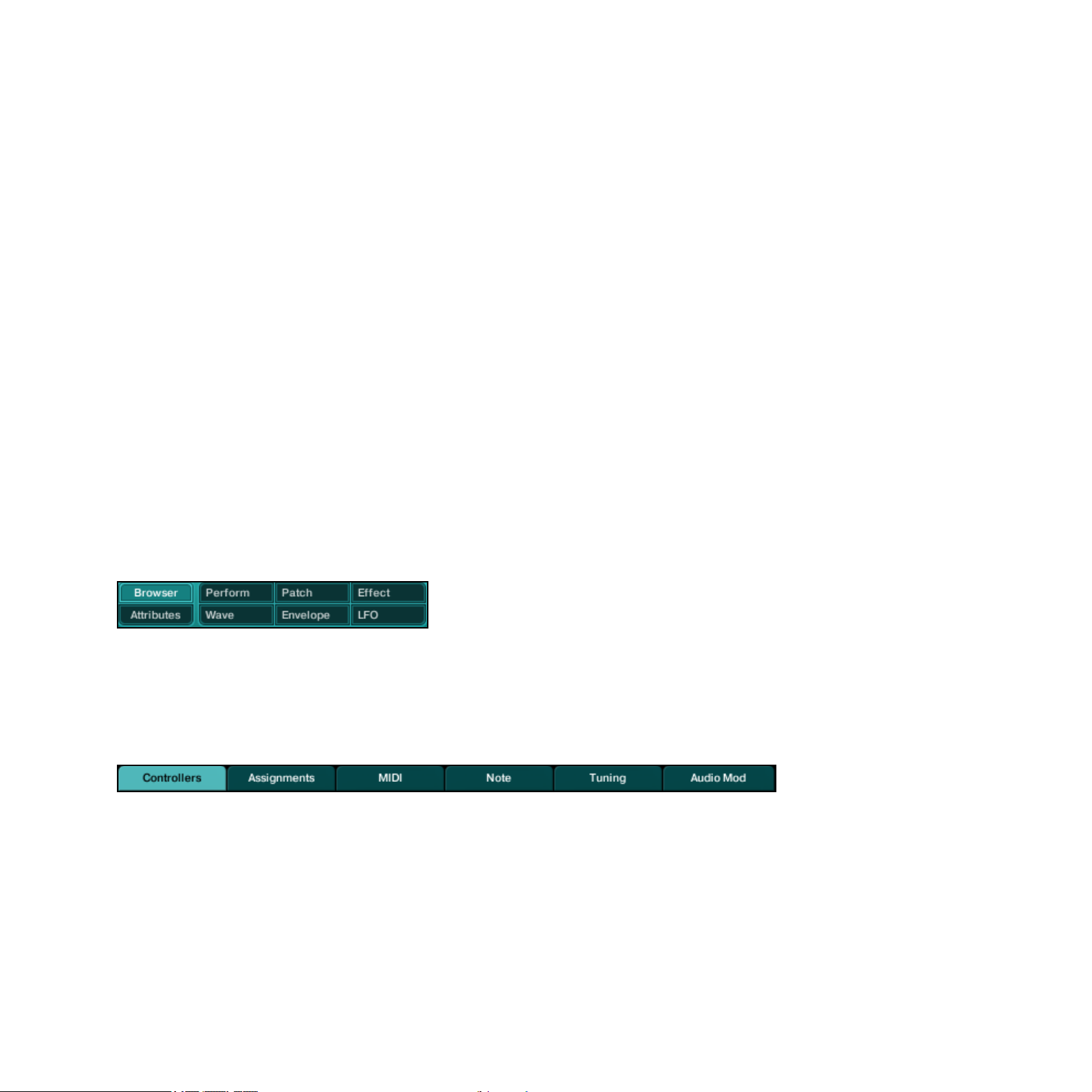
In the Wave and Perform Window, there is a number of distinct pages. Each page holds control elements related to a specic task. To switch to a particular page, click on the desired
tab at the top of the page. The tab for the active page is highlighted.
Page tabs within Perform Window
In the Patch Window, most modules can be switched between multiple panels. To switch to a
particular panel, click on the desired tab at the top of the panel. The tab for an active panel
is highlighted.
ABSYNTH 5 Reference Manual – 16
Page 17

Module in the Patch Window with highlighted Main panel
2.2 Buttons and Switches
Buttons and switches basically allow you to trigger a function or to activate/deactivate a feature.
Some other parts of the interface also work as switches: for example, you can turn individual
modules on and off in the Patch Window by clicking on the extended left border of each
Module Slot. You do not necessarily need to click on the writing, the entire left border area
works as a switch. The same applies to the effect within the Effect Window: clicking on the
thick border displaying Effect at the top left corner activates/deactivates the effect.
2.3 Menus and Selectors
Menus can be found in many areas in ABSYNTH 5. They contain lists of available options.
Menus can be recognized a small triangle pointing downwards.
Edit menu button available in all Windows
In order to choose an option or a command from a menu, click on it: A drop-down list appears, which remains open if you move the cursor. Click on the desired entry to select it. To
leave the menu without changing the setting, click somewhere else on the user interface or
press [Esc] on your computer keyboard.
Selectors are similar to menus, but instead of opening a drop-down list below the menu when
clicked, they open a separate pop-up dialog. Most of the time, you can not only select an entry
with them but also choose some other options. You then need to click on “OK” (or “Cancel”)
at the bottom to get back to the original Window. An example is the Wave Selector and its
companion the Wave Selection dialog, which can be found in many places in ABSYNTH 5.
ABSYNTH 5 Reference Manual – 17
Page 18

2.4 Value Fields
Value elds contain the numerical values of parameters. The values indicated can be changed
in a variety of ways:
•
Clicking within the eld: The value is highlighted and you can enter a value using your
computer keypad. Press [Enter] to conrm or [Esc] to let the value unchanged.
• Using the diamond button ( ) next to a value eld: Click on it and hold the mouse button
depressed. Drag the mouse up/down to increase/decrease the value, respectively. Depending
on the resolution of the parameter, you will see one, two or three diamonds next to its
value eld. The leftmost diamond has the biggest range – and the lowest resolution: use it
to change the value roughly. Use the other diamonds to make ner adjustments.
•
If your mouse has a scroll wheel, you can place the cursor on a diamond and change the
value by turning the scroll wheel. Move the wheel forward to increase the value and backwards to decrease it.
•
You can also right-click ([Ctrl]+click on Mac) on most value elds to bring up a contextual menu. Here you can assign the parameter to one of the Macro Controls. More specic information about Macro Controls can be found at section 10.2 “Automation in
ABSYNTH 5: Macro Controls”.
ABSYNTH 5 Reference Manual – 18
Page 19
2.5 Sliders and Knobs
Some parameter values can be changed via sliders and knobs.
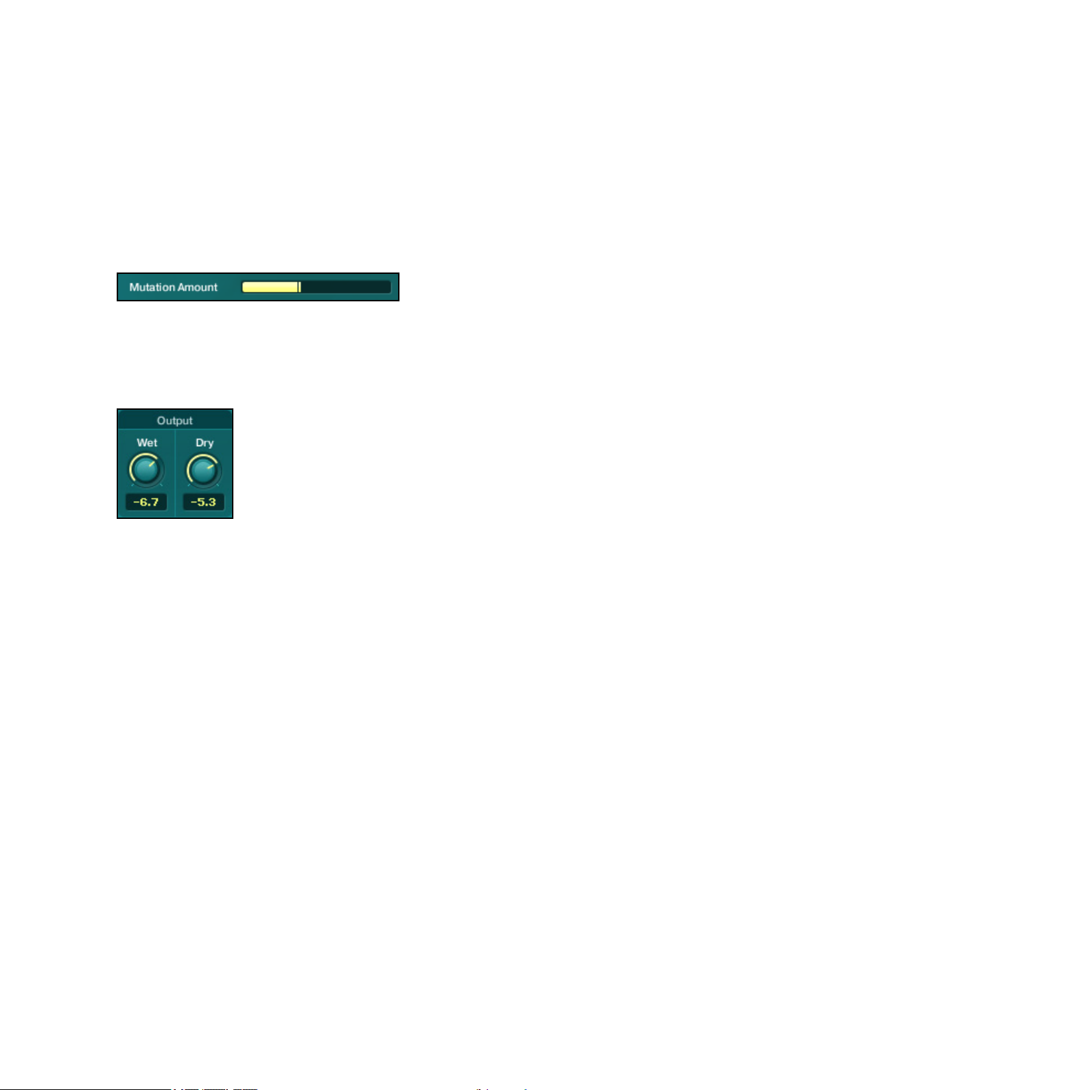
Sliders (or faders) are used for example to adjust the effect’s input levels in the Effect Window,
or to dene the mutation settings in the Browser Window’s Mutator. To adjust the value of a
slider, click on it and drag your mouse horizontally while holding the mouse button depressed.
Sider for Mutation Aamount in Browser Window
Knobs can be found for example in the Effect Window, where you adjust the signal proportions using the Wet Level an Dry Level controls.
Wet/Dry knobs in the Effect Window
The global Master Envelope also uses knobs to dene its four steps Attack, Decay, Sustain
and Release. To adjust the value of a knob, you have following possibilities:
•
Click on the knob (or on the value display if available) and drag the mouse up/down to
increase/decrease the value, respectively. If your mouse has a scroll wheel, you can place
the cursor on the knob and change its value by turning the scroll wheel. Move the wheel
forward to increase the value and backwards to decrease it.
•
Double-click on the value display (if available) and enter a new value via your computer
keyboard, then press [Enter] to conrm or [Esc] to let the previous value unchanged.
ABSYNTH 5 Reference Manual – 19
Page 20

3 Application Menu Bar
The Application Menu Bar (here on Windows version shown)
The Application Menu Bar is only available if you are using ABSYNTH 5 in stand-alone mode.
It holds commands dealing with the overall functioning of ABSYNTH5. Similar to the menu
bar found in other applications on your operating system, it contains three menus, detailed
below: the File menu, the Edit menu and the Help menu.
3.1 File Menu
The File menu contains the following entries:
•
NewSound: Creates a new empty Sound in ABSYNTH 5. The default new Sound only
contains one Oscillator in its Channel A.
• OpenSound…: Opens a dialog labeled Open SingleSound File… allowing you to select a
Sound on your hard drive for opening. In the dialog, navigate to the desired Sound, select
it and click on “Open” (or double-click on the Sound). The Sound replaces the Sound
previously loaded in ABSYNTH 5.
•
RecentFiles: Opens a submenu containing shortcuts to the 10 last Sounds that you
opened in your last sessions. Select an entry in the submenu to open the corresponding
Sound. At the bottom of the submenu, the entry Clear Menu empties the submenu.
• SaveSound: Allows you to save the changes made to the currently loaded Sound. If you
did not save the current Sound yet, this command automatically opens the Save Sound
As dialog (see below).
•
SaveSoundAs…: Opens a dialog labeled Save SingleSound File As… allowing you to save
the current Sound under a new name. In the dialog, navigate to the desired folder where
you want to save your Sound, type a new name for the Sound and click on “Save”.
We recommend saving sounds to the default path, “My Sounds.” This way, your Sound
!
will automatically be integrated to the ABSYNTH 5 Database upon saving.
ABSYNTH 5 Reference Manual – 20
Page 21

• ImportGloBank…: Opens a dialog labeled Please select a glo bank to import… allowing
you to import Sounds made with older versions of ABSYNTH into ABSYNTH 5. Navigate
to the desired Glo bank on your hard drive, select it and click on “Open”. You can then
scroll through the list of Sounds available in this bank. The Sound selected in the list is
automatically loaded in ABSYNTH 5 and you can play it. Should you wish to convert this
Sound into an ABSYNTH 5 KORE SOUND®, you can save it like any other Sound via the
Save/Save As… commands explained above.
The Factory Contents of all previous versions of ABSYNTH have already been converted
!
Sounds only!
and are directly available via the Browser Window. Thus, you need this command for User
• Options…: Opens the Options dialog, which will be explained in detail later (see section
3.4 “Options Dialog” below).
•
AudioandMIDISettings…: Opens the Audio and MIDI Settings dialog allowing you to
adapt ABSYNTH 5 to your custom studio or live setup. The audio and MIDI settings are
explained in detail in the Getting Started guide.
•
Exit: Quits the application. Please check that you saved your Sound before closing. I you
did not, unsaved changes will be lost!
ABSYNTH 5 Reference Manual – 21
Page 22

3.2 Edit Menu
The Edit menu contains the following entries:
• Undo: Cancels the last action in ABSYNTH 5.
•
Redo: Cancels the last Undo command – in other terms, re-executes the last cancelled action.
•
Copy: Stores the selected Envelope (if in Envelope Window) or Waveform (if in Wave
Window) to the clipboard.
•
Paste: Pastes the Envelope or Waveform stored in the clipboard (via the command Copy above).
•
Balancelevels: Equilibrates the three Channels A, B and C at a level that prevents the
overall output from clipping.
3.3 Help Menu
The Help menu contains three entries with further information about ABSYNTH 5:
•
LaunchServiceCenter: Starts the NI Service Center. The Service Center can activate
ABSYNTH 5 as well as search for new updates. Detailed information can be found in the
Service Center Quick Start Guide and manual.
• VisitAbsynthontheWeb: Opens the ABSYNTH page on the Native Instruments website
in your favorite Internet browser, where you can access up-to-date information on
ABSYNTH 5.
•
AboutAbsynth…: Opens the About screen where you can view the version number and
the individual serial number of your copy of ABSYNTH5. You also nd there the names
of all the people who worked on ABSYNTH5.
ABSYNTH 5 Reference Manual – 22
Page 23
3.4 Options Dialog
The Options dialog provides you with various options that shape global functions in ABSYNTH5.
You can call the Options dialog by selecting the corresponding entry in the File menu of the
Application Menu Bar (stand-alone application only) or in the File menu of the Navigation Bar
(see section 4 “Navigation Bar” below).
The Options dialog is organized into three pages: General, Surround and Browser. Each of
them can be accessed by clicking on the corresponding tab at the top of the Options dialog.
To conrm any changes made to the options, click on “Done” at the bottom of the dialog.
To close the dialog without saving your changes, click on the dialog’s close icon instead (its
location depends on your operating system).
We describe hereafter all available options.
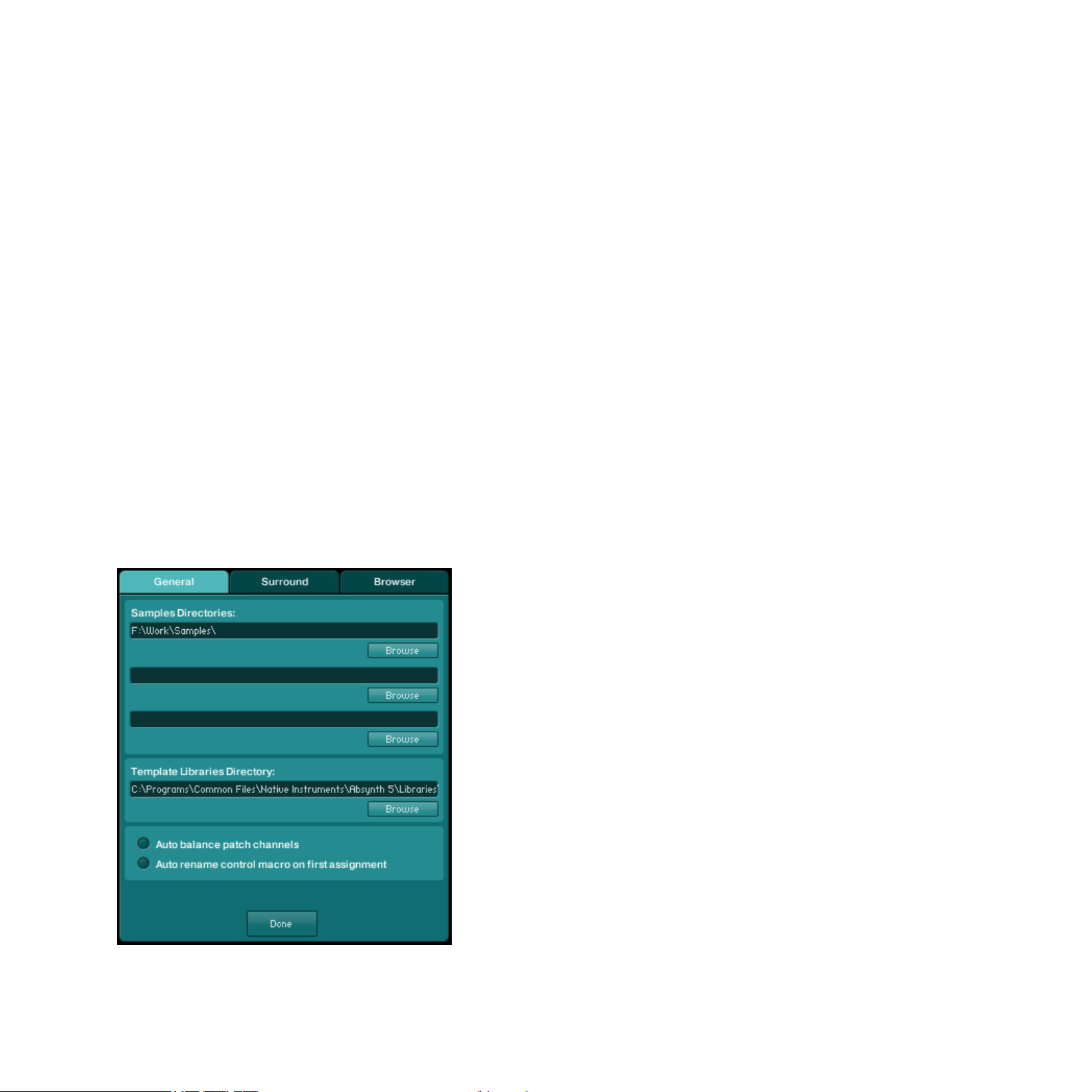
3.4.1 General Page
The General page allows you to dene the paths for the directories containing your samples
and your templates, along with two additional options:
The General page of the Options dialog
ABSYNTH 5 Reference Manual – 23
Page 24
• SamplesDirectories: These three elds allow you to set paths to the directories contain-
ing the samples used by your Sounds. To dene a path, click on the Browse button under
one of the elds, navigate to the desired folder on your hard drive and click “OK.”
•
TemplateLibrariesDirectory: This eld allows you to set the path for the directory containing your various Templates (Envelopes, Waveforms, modules, Channels…). To change the
path, click on the Browse button under the eld, navigate to the desired folder on your
hard drive and click on “OK.” For more info on the Templates, please refer to section
5.2.3 “Universal Library.”
•
Autobalancepatchchannels: If this option is enabled, ABSYNTH 5 controls the output
of the three individual Channels in the Patch Window so that the main output remains
constant and do not clip. That is, if you were to increase the level of one Channel,
ABSYNTH 5 would automatically decrease the levels of the two other Channels.
•
Autorenamecontrolmacroonrstassignment: If this option is enabled, a Macro Control
that has had a parameter assigned to it takes over the name of this parameter – but only
if no other parameters have already been assigned to it.
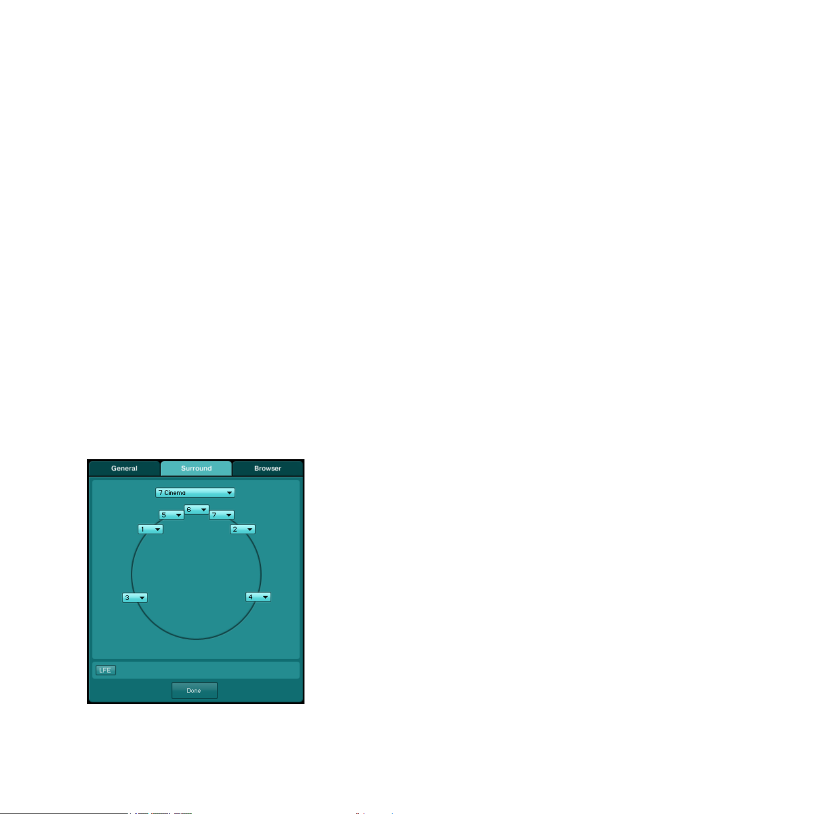
3.4.2 Surround Page
The Surround page allows you to congure ABSYNTH5’s surround output channels.
The Surround page of the Options dialog
ABSYNTH 5 Reference Manual – 24
Page 25

ABSYNTH5 can have up to eight separate audio outputs. The fundamentals for conguring
your audio and MIDI interfaces can be found in the Getting Started guide. The Surround page
can then be used to assign your output channels to specic positions in the panoramic eld.
In the Surround menu sitting at the top of the page, you can choose from the following congurations:
•
2Stereo: This standard conguration delivers typical two-channel stereo sound. In this
setting, the speakers are situated at 45 degrees and -45 degrees.
•
2StereoWide: This conguration is easy to distinguish from 2 Stereo: Both front speakers are arranged at 90° and -90°. This results in a wider stereo soundscape.
• 3Surround: This conguration returns to analog Matrix surround sound. It is well known
under the names of, for example, Dolby Surround™ (home entertainment center) or Dolby
Stereo™ (movie theatre), but without a front center channel. Here, there is a central rear
channel as well as left- and right front ch3 Front: This conguration replaces the central
rear channel of the previous conguration with a center front channel, which leads to
better distribution in the stereo soundscape than a classic stereo conguration.
•
4Surround: This conguration combines a 3 Surround conguration with a front-center
channel and is also known under the name Dolby Surround Pro Logic™.
•
4Quad: This four-channel conguration is based on the quadraphonic systems that were
popular with consumers in the 1970’s. The four speakers are arranged symmetrically in
a square shape.
•
5Music: This ve-channel surround sound conguration is comparable to top-of-the-line
home theater arrangements and movie theaters systems, known as, for example, Dolby
Digital™ or DTS™. This system provides you with three front channels (left, center, right)
and two surround channels (surround left, surround right).
•
5Pentaphonic: This conguration delivers ve-channel surround sound, where the ve
channels are arranged symmetrically in a circle.
• 6Music: This conguration corresponds to a 5 Music conguration, but contains an ad-
ditional rear center channel. This arrangement is used by, for example, the surround sound
systems Dolby Digital EX™ and DTS-ES™.
ABSYNTH 5 Reference Manual – 25
Page 26

•
6Hexaphonic: This conguration delivers six-channel surround sound where the six channels are symmetrically arranged in a circle.
•
7Cinema: This conguration delivers seven-channel surround sound as it can often be
heard in lms. Well-known surround sound systems of this type include SDDS™ and
IMAX™. This conguration combines the 5 Music congurations with two additional front
center channels (center left, center right).
•
7Music: This conguration delivers seven-channel surround sound. It is comparable with
the 6 Music conguration, but the surround center channel is divided between the two
rear channels “surround center left” and “surround center right”.
•
7Heptaphonic: This conguration delivers seven-channel surround sound, where the
seven channels are symmetrically arranged in a circle.
• 8Octaphonic: This conguration delivers eight-channel surround sound, where the eight
channels are symmetrically arranged in a circle.
For any of these congurations, you can then set the assignment of each channel to the
available audio outputs of the stand-alone version. The audio outputs that you congured in
the Audio and MIDI Settings dialog are at your disposal in the various Channel menus sitting in the panoramic eld (the position and number of these menus vary with the selected
conguration, see above).
Low Frequency Effect Channel
For all congurations but the last 8 Octophonic, you can activate an additional LFE (Low
Frequency Effects) or Subwoofer channel. To enable it, click on the little LFE button at the
bottom left of the Surround page.
The LFE channel settings
When activated, you see other parameters appearing on its right:
•
Channelmenu: An additional Channel menu lets you dene the output to assign to the
LFE channel.
ABSYNTH 5 Reference Manual – 26
Page 27

• Frequencycontrol: Lets you dene the cutoff frequency (in Hz) for this channel.
• Dampingcontrol: Lets you adjust the level (in dB) of this particular channel according to
your subwoofer.
When using ABSYNTH5 as a plug-in, the host automatically chooses the correct setting for
the track in which ABSYNTH5 is used: a particular plug-in will be used depending on whether
you use ABSYNTH5 as an instrument or as an insert effect, and whether the according track
is a stereo track or a surround track.
3.4.3 Browser Page
In the Browser page, you can set options in relation with the Database.
The Browser page of the Options dialog
In the top part of the page, you nd the following settings:
• DefaultAuthor: Allows you to dene a default text string for the Author eld in the Meta
Information of the Sounds.
•
UseDefaultAuthorforNewSound:If this option is activated, the default Author name
dened above is inserted into the Meta Information of all newly created Sounds.
ABSYNTH 5 Reference Manual – 27
Page 28

•
UseDefaultAuthorforSaveSoundAs: If this option is activated, the default Author name
dened above is inserted into the Meta Information of all Sounds stored via the command
Save Sound As (see 3.1, “File Menu”, above).
•
DatabaseHit-Count: This menu allows you to customize the displayed information for each
Attributes in the Browser Window. If None is selected, only the Attributes’ names are
shown. If Indicate Empty Categories is selected, the Attributes for which there is no Sound
are grayed out. If Show Count as Number is selected, the Browser displays after each
Attribute’s name the number of Sounds having this Attribute.
Note that for the two last entries Indicate Empty Categories and Show Count as Number,
!
selection of Attributes: for example, if the Attribute Solo/Single is selected in the category Source
for the Instruments, the Attribute Ensemble/Kit will logically be grayed out (and the number behind
it will be 0). This allows you to quickly see, upon each selection you make, which other Attributes
are possible (and how many Sounds have these Attributes).
the current state (and number) displayed after each Attribute name depends on the current
In the bottom part of the page, you can dene the list of folders to scan for Sounds. You can
add/remove folders to/from the list via the respective buttons at the bottom. Remember that
subfolders in the selected folders will automatically be included in the search as well.
Should you ever make changes in this page, or delete/add individual Sound les in the corresponding folders using your operating system, then you must rebuild the Database. In order
to do this, use the Rebuild Database button (labeled Rebuild DB), at the bottom right corner
of the page. Depending on the number of available KORE SOUNDS, this process can be
time-consuming. Only then will the changes take effect in the Database.
ABSYNTH 5 Reference Manual – 28
Page 29
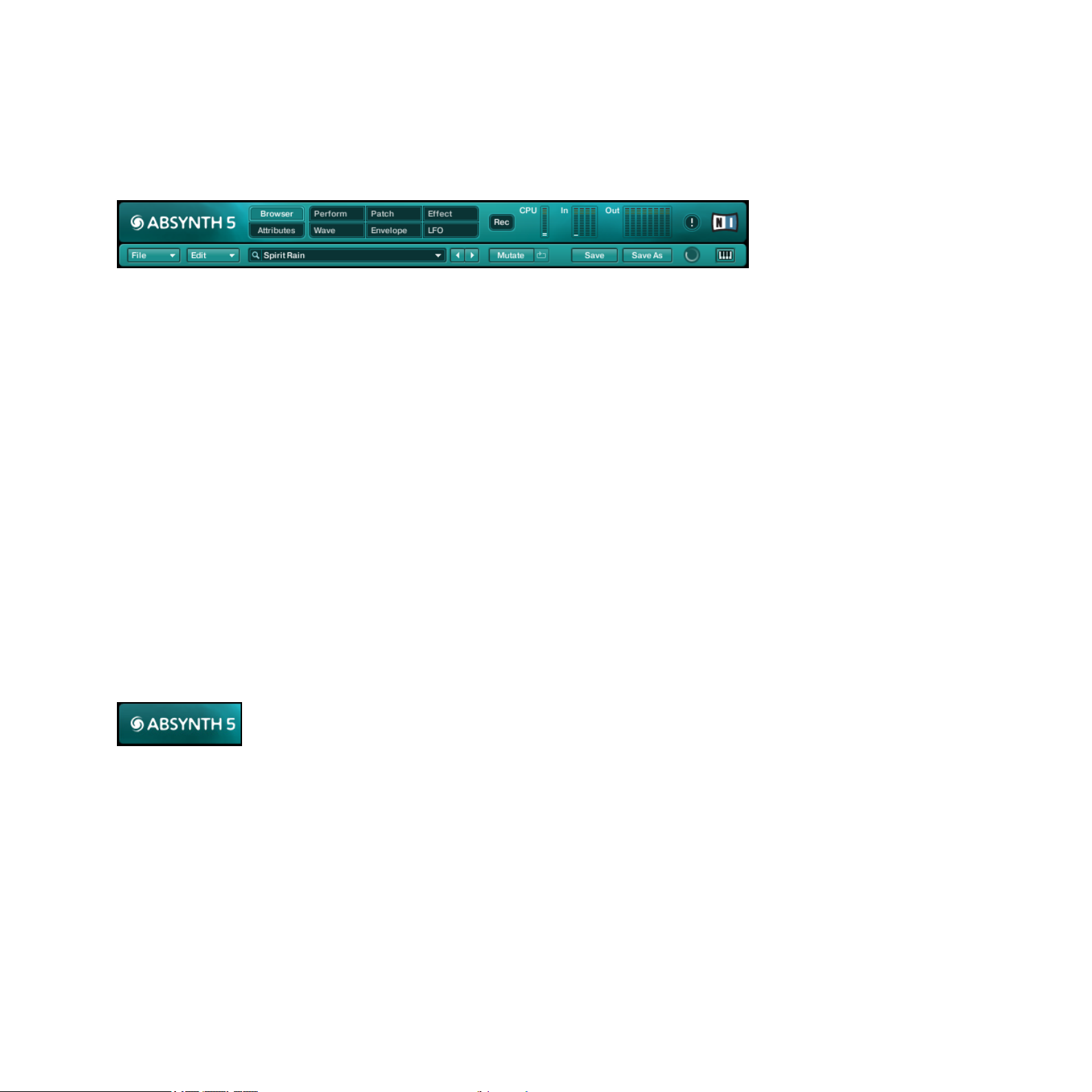
4 Navigation Bar
The Navigation Bar is located at the very top of the ABSYNTH5 interface:
The Navigation Bar
It consists of two lines:
• In the top line of the Navigation Bar you see (from left to right) the ABSYNTH logo, the
tabs opening the different Windows, the Record button, the CPU meter, the Input and
Output Level meters, the Panic button and the NI logo. More information about these
features is available below.
•
The bottom line includes mostly options to load and save Sounds and navigate through
the Library.
4.1 Top Row: Global Controls
4.1.1 ABSYNTH 5 Logo
Interactive ABSYNTH button
Clicking on the ABSYNTH5 logo has the same effect as clicking on the NI logo: both open
the About screen. This About screen contains some important information: the version number, license type and serial number of your copy of ABSYNTH5, along with the list of all the
people who worked on this great synth!
ABSYNTH 5 Reference Manual – 29
Page 30
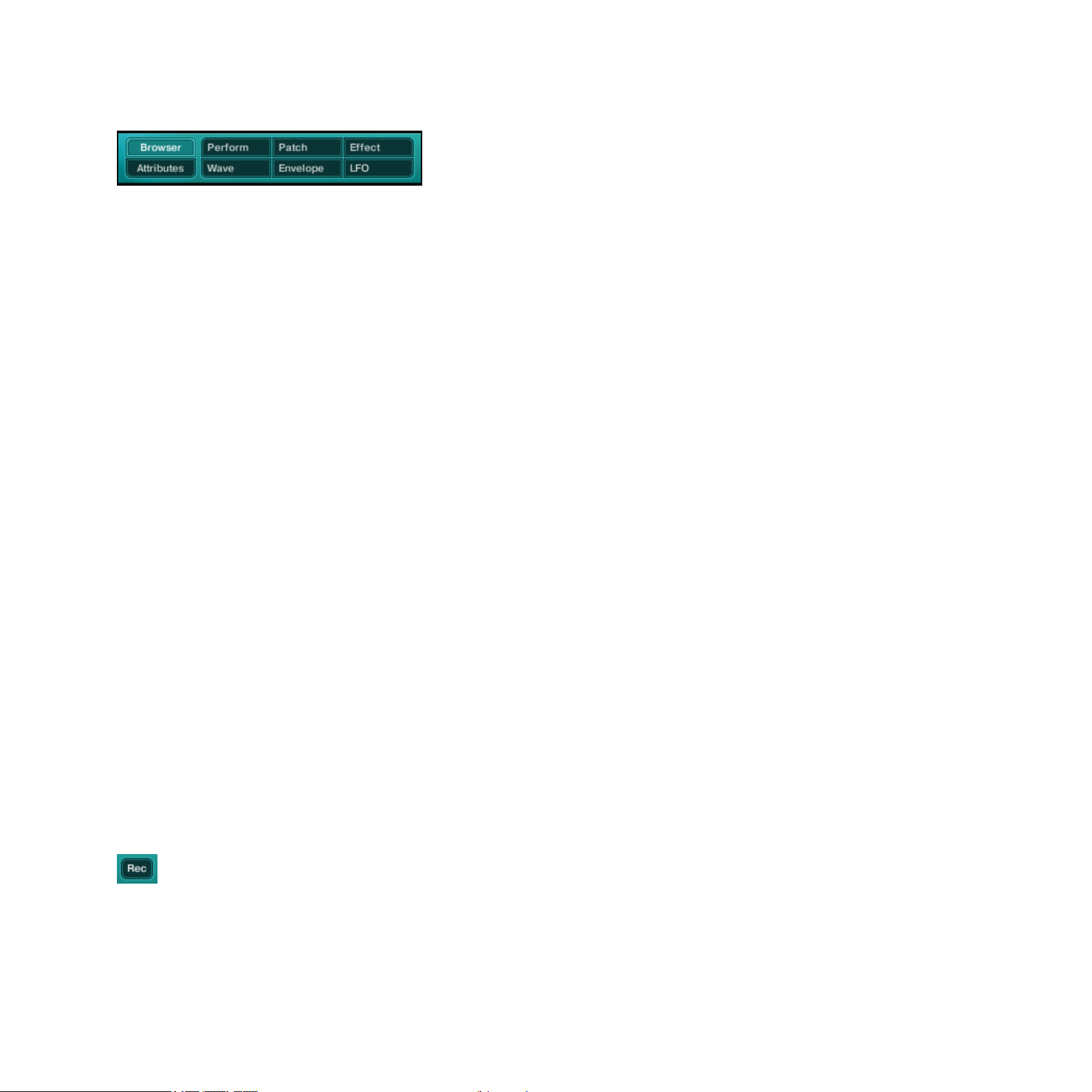
4.1.2 Window Tabs
Window tabs in Navigation Bar
These eight tabs allow you to select a particular Window to display. As already mentioned, a
Window is a specic work environment in ABSYNTH5 (see section 2.1, “Windows, Pages,
Panels and Tabs”, above). The following Windows are available: Browser, Attributes, Perform,
Patch, Effect, Wave, Envelope and LFO. To activate a particular Window, click on the eponymous tab. ABSYNTH5 replaces the currently displayed Window with the new selected one
and the corresponding tab gets highlighted.
Opening Several Windows Simultaneously
In the stand-alone version of ABSYNTH5 you can open a Window in the main ABSYNTH5
interface in a new pop-up window instead of replacing esion of ABSYNTH5:, hold [Ctrl]
(Windows Vista/XP) or [Cmd] (Mac) depressed while clicking on one of the tabs in tup Window
instead. This works for the following tabs/Windows: Patch, Effect, Wave, Envelope and LFO.
This can be very handy, especially if you have a large computer screen: you can display two
or more Windows, place them where you want on your screen and work simultaneously on
different parts of ABSYNTH5, both giving you a better overview of various ABSYNTH5
components and preventing you from switching back and forth between different Windows.
Opening Windows simultaneously is only available in stand-alone mode!
!
4.1.3 Record Button
Record button
A click on the d button shows/hides the Audio Recorder. For more info on the Audio Recorder,
please refer to section 12.2 “Audio Recorder”.
ABSYNTH 5 Reference Manual – 30
Page 31

4.1.4 CPU Meter
The CPU meter indicates the processing load being used by ABSYNTH 5.
CPU meter
When the computer‘s processor is overloaded, distortions and audio drop-outs are very likely
to happen during playback. To avoid this, it is worth keeping an eye on the CPU meter.
The processing load depends above all on two factors: the complexity of the Sound and the
number of voices played. ABSYNTH5 uses a dynamic voice allocation; voices that are not
played do not contribute to the processing load. The more notes are played simultaneously,
the higher the CPU read-out will go. If the CPU overloads, it is recommended to leave out a
couple of notes in order to reduce the processing load. If your computer reacts sluggishly to
incoming commands, it is probably because your CPU is overloaded and there is not enough
resources available for generating the image on the screen. If this happens, try to decrease
the load by releasing a few notes.
If ABSYNTH5 overloads the CPU, the audio hardware installed on your computer might get
out of step and no longer be able to accurately produce sound. In such a case, you have
several options to restore operations back to normal:
►
Release all of the notes on your MIDI keyboard. This releases resources used by ABSYNTH
5 for every voice.
►
Click on the Panic button in order to reset the ABSYNTH5 engine, and stop playing (see
section 4.1.6 below).
►
Click on the Next or Previous Sound button to switch to another Sound (see section 4.2.3
below).
►
Click on a Module Slot frame in the Patch Window to turn a Module on or off. This will
also reset ABSYNTH 5’s audio engine.
ABSYNTH 5 Reference Manual – 31
Page 32

4.1.5 Input and Output Level Meters
The Input and Output Level meters indicate the levels of the incoming and outgoing audi signals:
Input Output Llevel meters
The four LED chains labeled In indicate when a signal is going into an Oscillator module. You can
read the levels of the outgoing signals on the eight LED chains labeled Out. As explained in the
section on surround congurations in the Options dialog (see 3.4 above), ABSYNTH5 can handle
up to eight simultaneous audio outputs. Each of these eight outputs has its own LED chain.
4.1.6 Panic Button
Panic button
The Panic button allows you to interrupt the audio playback in ABSYNTH 5, in case something goes wrong and unwanted sound is being produced. Click on the Panic button to reset
the audio engine of ABSYNTH 5 and to stop the playback process. All of the MIDI notes that
have been “left hanging” will also reset.
4.1.7 NI Logo
Interactive NI logo
Clicking on the NI logo has the same effect as clicking on the ABSYNTH 5 logo: it opens the
About screen. This About screen contains some important information: the version number,
license type and serial number of your copy of ABSYNTH 5, along with the list of all the
people who worked on this great synth!
ABSYNTH 5 Reference Manual – 32
Page 33

4.2 Bottom Row: Sound Management
4.2.1 File and Edit Menus
File menu and Edit menu
The File menu and Edit menu mirror the File menu and Edit menu of the Application Menu
Bar in stand-alone mode, except the entries Audio and MIDI Settings… and Exit, missing
from the File menu here.
Therefore, please refer to section 3.1, “File Menu”, and 3.2, “Edit Menu”, for more info on
the commands found in the File menu and Edit menu, respectively.
4.2.2 Sound Name Display and Sound Menu
Sound Name display / Sound menu
The Sound Name display / Sound menu shows the name of the Sound currently loaded. A
click on the display opens the Sound menu that lets you choose another Sound to load from
the current Search Result List or from the current folder:
•
If you used the Browser’s Database view to nd and load the current Sound from the
Search Result List, then a small magnifying glass icon appears to the left of the Sound
Name display. The Sound menu then shows the Sounds from the current Search Result
List (see section 11.2.1 “Database View” for more info).
•
If you loaded your Sound from the File Tree view, then a small folder icon appears to the
left of the Sound Name display, and the Sound menu shows the Sounds available within
the same folder from which you loaded the current Sound (see section 11.2.2, “File Tree
View”, for more info).
•
If you loaded your Sound from the Program List, a small MIDI plug labeed PC appears
instead, and the Sound mMenu displays all Sounds that you added to the Program List
(see section 11.2.3 “Programs” for more info).
ABSYNTH 5 Reference Manual – 33
Page 34

At the top of the Sound menu, the subentry Mutate History allows you to select one of the
existing Sound Mutations stored in the Mutation History. For more info on the Mutator and
the Mutation History, please refer to section 11.3, “Mutator.”
4.2.3 Previous/Next Sound Buttons
Previous/Next Sound buttons
These buttons allow for quick-scanning through the Search Result List, the current folder or
the Program List: the behavior of the Previous/Next Sound buttons depends on the view that
you used to load the current Sound:
• If you used the Browser’s Database view, they scroll through your current Search Result
List.
• If you used the Browser’s File Tree view, they scan the content of the folder from which
you loaded the current Sound.
• If you used the Program List, they scroll through your Program List.
For more info on these concepts, please refer to section 11.2, “Searching and Loading Sounds
with the Browser”.
4.2.4 Mutate and Retry Buttons
Mutate and Retry buttons
The Mutate and Retry buttons are shortcuts for the Mutate button and Retry button of
the Mutator in the Browser. For more info on their functions, please refer to section 11.3,
“Mutator”.
ABSYNTH 5 Reference Manual – 34
Page 35

4.2.5 Save and Save As Buttons
Save and Save As buttons
The Save and Save As buttons are shortcuts for the Save and Save As… commands found
in the File menu (see their description at section 3.1, “File Menu”, above).
Further instructions on loading, saving and administration of Sounds can be found in chapter
11, “The Browser and Attributes Windows”, which also provides an extensive description of
ABSYNTH5’s Browser.
4.2.6 Database Activity Indicator
Database Activity indicator
The Database Activity indicator shows up when ABSYNTH5‘s Database is being updated. The
indicator only appears when ABSYNTH5 currently does maintenance work on the Database –
typically when you triggered the Rebuild Database button.
You can continue your current work during Database activity, but the Browser might not
!
functional again.
display all results in Database view: wait a few moments, and the Database will be fully
4.2.7 Keyboard Button
Keyboard button
A click on the Keyboard button shows/hides the Virtual Keyboard at the bottom of ABSYNTH
5‘s interface. For more info on the Virtual Keyboard, please refer to section 12.1, “Virtual
Keyboard”.
ABSYNTH 5 Reference Manual – 35
Page 36

5 Patch Window
Patch Window with several active Module Slotss
The Patch Window is the control center of ABSYNTH 5 where you assemble the components
that make up a Sound. These components contribute to producing and shaping the desired
output. The modules represent the individual components in the Patch Window. There are different types of modules: Oscillator modules are the sound sources of ABSYNTH 5. Modulator
modules, Filter modules and Waveshaper modules shape the sound. In the following sections
yu will nd detailed descrptions of the different mModules and their features.
ABSYNTH 5 Reference Manual – 36
Page 37

5.1 Signal ow in the Patch
As you know from the Getting Started guide, the design of ABSYNTH5 is semi-modular.
That means that you can determine the arrangement of certain components yourself. Other
components have a permanent place in the signal ow.
5.1.1 Combining Modules in the Channels
The Patch Window organizes the modules components into three Channels. These Channels
are designated with the letters A through C and they each consist of three vertically arranged
elds, the Module Slots. Each of these Module Slots can be lled with a module. To turn a
module on or off, click on the extended border on the left side of the Module Slot – where
the writing indicates the type of module.
When inserting the modules, the following rules apply:
•
The Module Slots A-C at the top of the three Channels can only be loaded with an
Oscillator module.
•
The remaining Module Slots 1 and 2 of any Channel can be loaded with Modulator, Filter
or Waveshaper modules.
While the Oscillator module always works as a signal source, the other modules can shift
!
will appear in the border of the Module Slot. Once activated, its Type menu allows you to switch
between the operating modes Filter, Modulator and Waveshaper. So, for example, you can insert
Filter modules into both Slots of one Channel, and insert two Waveshapers into another Channel.
between different types of operation: If you turn on a module, then this module type
ABSYNTH 5 Reference Manual – 37
Page 38

5.1.2 Channel Level controls
Beneath Channels A, B, and C you can see three horizontal sliders, known as the Channel
Level controls. These sliders allow you to adjust the levels of the three Channels:
Channel Level controls
ABSYNTH 5 can also adjust the levels automatically so that the sum of the three audio signals never exceeds 0dB, even after a value in one of the three Channels has been changed.
To activate automatic volume levels, activate the option Auto balance patch channels in the
General page of the Options dialog (see section 3.4, “Options Dialog”, for more info). You
also have the possibility to balance Channels manually, giving the ame level to each. To do
this, select the entry Balance lLevels from the Edit menu in the Navigation Bar or in the
Application Menu Bar (stand-alone version on
5.1.3 Surround Pan Switch
The Surround Pan switch, which is located in the lower left-hand corner of the Patch Window,
allows you to activate/deactivate the Surround Pan mode:
Surround Pan switch
This mode allows you to freely position the three Channels in the surround panorama. This
function can be used for impressive spatial effects, for example, by modulating the surround
position of the Channels independently of one another with an LFO or an Envelope. More information about this is available in the chapters 8, “Envelope Window” , and 9, “LFO Window”.
ABSYNTH 5 Reference Manual – 38
Page 39

5.1.4 Master Channel
Active Master Channel modules
The signals delivered by the activated Oscillator modules run through the other activated
modules in each Channel, and are then mixed in the Master Channel, which is arranged
horizontally at the bottom of ABSYNTH 5‘s interface. In the Master Channel, the signal runs
from the left to the right.
In this Channel, there is a Module Slot reserved for a particular module: the Effect module,
which can always be found at the bottom-right of the Patch Window – thus at the end of
the module chain. The other two Module Slots in the Master Channel can be inserted with
Modules of your choice (except Oscillator modules).
After the Effect module, the nal signal leaves ABSYNTH 5.
The glowing connection wires between activated modules visualize the signal ow!
%
ABSYNTH 5 Reference Manual – 39
Page 40

5.1.5 Mono Mode and Poly Mode in the Master Channel
The modules in the Master Channel have two operating modes: Poly mode and Mono mode.
You can switch between both modes by clicking on the Mono/Poly switch:
Mono/Poly switch
•
In Mono mode (three arrows meeting each other), the signals coming from the three
Channels A-C are summed up before being processed by the module.
• In Poly mode (three parallel arrows), the module processes each Channel separately.
As a logical consequence, you cannot have a module in Poly mode sitting after a module
!
rst module…
The difference between the two modes can be heard particularly clearly in the Waveshaper
in Mono mode, since the three Channel signals have already been summed up by the
module: In Poly mode every voice has its own, independent Waveshaper. The distortion affects
every voice separately – in the same way as if every string on a guitar had its own amplier.
In Mono mode, only one Waveshaper is used for the different voices, which means that many
of the notes played interact – similar to the way that they do in chords played on a distorted
electric guitar. You can try out the effect simply by inserting a Waveshaper module into the
Master Channel. Play a couple of sounds and switch between both modes by clicking on the
Mono/Poly switch. You will see that the Mono mode reacts with signicantly stronger distortion as you begin to play multiple notes. This is because the signals of the different voices
are assembled before the Waveshaper input, which results in a higher input gauge. In Poly
mode, by contrast, the voices are distributed among multiple Waveshapers and thus produce
lower signal levels.
For low level input signals, the Waveshaper in Mono mode works like a simple compressor
%
and lends itself well to compressing and heating up the input signal.
ABSYNTH 5 Reference Manual – 40
Page 41

5.2 Common Features for all Modules
The various modules available in the Patch Window share these common features:
• Edit menu
• Panels and tabs
• Template functionality and Universal Library
5.2.1 Edit Menu
The Edit menu for a Filter module.
Each module offers an Edit menu in its upper left corner. This Edit menu holds global functions for that module. Its entries are grouped as follows:
• The rst entries allow you to copy the current settings of the module to the clipboard in
order to paste them later in another module of the same type, and to paste within the
module the settings previously stored in the clipboard. The Oscillators additionally offer
to copy/paste the entire Channel.
•
The following entries allow you to save and load Templates, i.e. pre-congured modules/
Channels with all their settings (see the section 5.2.3, “Universal Library”, below for more
info on this).
• The last two entries allow you to apply a Mutation and to retry a Mutation, both for that
particular module. The settings for this Mutation are those dened inutation section
Mutator section (see section 11.3, “Mutator”, for more on this).
ABSYNTH 5 Reference Manual – 41
Page 42

5.2.2 Panels and Tabs
Each module can have up to three panels organizing the various module parameters. Each
panel can be called by clicking on the corresponding tab at the top of the module.
The available panels depend on the type of the module (Oscillator, Filter, Modulator or
Waveshaper) as well as on the specic mode for each module type. You will nd a complete
list of available panels in the module-specic sections below.
5.2.3 Universal Library
The Universal Library in ABSYNTH5 makes it easier to bring together complex Sounds. You
can save and load so-called Templates for individual Waveforms, Envelopes, Effects, complete
modules with the appropriate Envelopes, and even entire Channels from the Universal Library.
The actual location of the Universal Library on your hard drive can be changed in the
!
3.4, “Options Dialog”, for more info on the Options dialog).
Options dialog via the option Template Libraries Directory of the General page (see section
In the Patch Window, you can save and load Channels, modules and Effect settings together
with all their relevant Envelopes. When you save a Channel, a module or Effect settings as a
Template in the Universal Library, the Envelopes are automatically led with it.
To load Templates, choose the category you want from the module’s Edit menu:
•
In an Oscillator, select the option Load Oscil Template to load a pre-congured Oscillator.
The command Load Channel Template allows you to load a complete Channel.
•
In a Filter, Modulator or Waveshaper module, the Edit menu solely offers a Load Template
option that loads the settings for that module.
ABSYNTH 5 Reference Manual – 42
Page 43

To save Templates, the method is similar:
•
In an Oscillator, select the option Save Oscil Template to save a pre-congured Oscillator.
The command Save Channel Template allows you to load a complete Channel.
•
In a Filter, Modulator or Waveshaper module, the Edit menu solely offers a Save Template
option that saves the settings for that module.
ABSYNTH 5 sorts the Library automatically for you: for example, you cannot load a Filter
!
The Patch Window is not the only location with access to the Universal Library. In the Envelope
Window and in the Wave Window you can also load and save Templates. For example, you
can store individual Envelopes and Waveforms in the Library. In the Envelope Window and
Wave Window, you can access the Universal Library via the Transform menu.
ABSYNTH5 includes an extensive Library of Channels, modules, Envelopes, Effects settings
and Waveforms. To see how quickly the prefabricated Channels from the Library can help you
Template into an Oscillator nor save a Waveshaper Template in the Envelopes folder.
to build a complex Sound, simply do the following:
1. Click on the left margin of an empty Oscillator Module Slot in the Patch Window to ac-
tivate the Oscillator.
2.
Choose the entry Load Channel Template… from the Edit menu on the upper left corner
of the Oscillator. The Channel Templates list opens up immediately.
3.
Choose the desired entry from that list and click on “OK.” Your Channel is now well
populated.
4. Do the same with the other two Channels.
→
You created a complete Sound in just a few seconds where it could have taken hours
“by hand!”
ABSYNTH 5 Reference Manual – 43
Page 44

Using Old Personal Templates
If you want to use ABSYNTH 4 Templates in ABSYNTH5, you need to copy them to the new
Libraries folder.
•
On Mac OS X, your old Templates are located by default in the directories “HD:Library/
Application Support/Native Instruments/Absynth 4/Libraries/[subdirectories]”.
Please be careful! On a Mac, you should not replace the ABSYNTH5 Libraries folder with
!
Templates! Instead, you should open each folder contained therein and copy the contents of each of the
lowest level subfolders manually to the corresponding subfolder in the ABSYNTH5 Libraries directory.
•
On a PC, your old Templates are located by default in the directories “C:\Programs\Shared
Files\Native Instruments\Absynth 4\Libraries\[subdirectories]”. You should be able to simply copy and paste the whole ABSYNTH 4 Libraries folder to the ABSYNTH 5 Libraries
folder and click on “Replace all”.
the ABSYNTH 4 Libraries folder, since Mac OS X would overwrite all the new ABSYNTH5
In any case, we recommend you to back up your ABSYNTH 5 Libraries folder before touching it!
5.3 Common Features in Many Modules
The following features appear in many situations. Knowing them is very helpful for understanding of the modules’ capabilities:
• Waveform Selector and Waveform Selection dialog
• Frequency meu/control
• Anti-Alias Switch
• Phase Inverter
ABSYNTH 5 Reference Manual – 44
Page 45
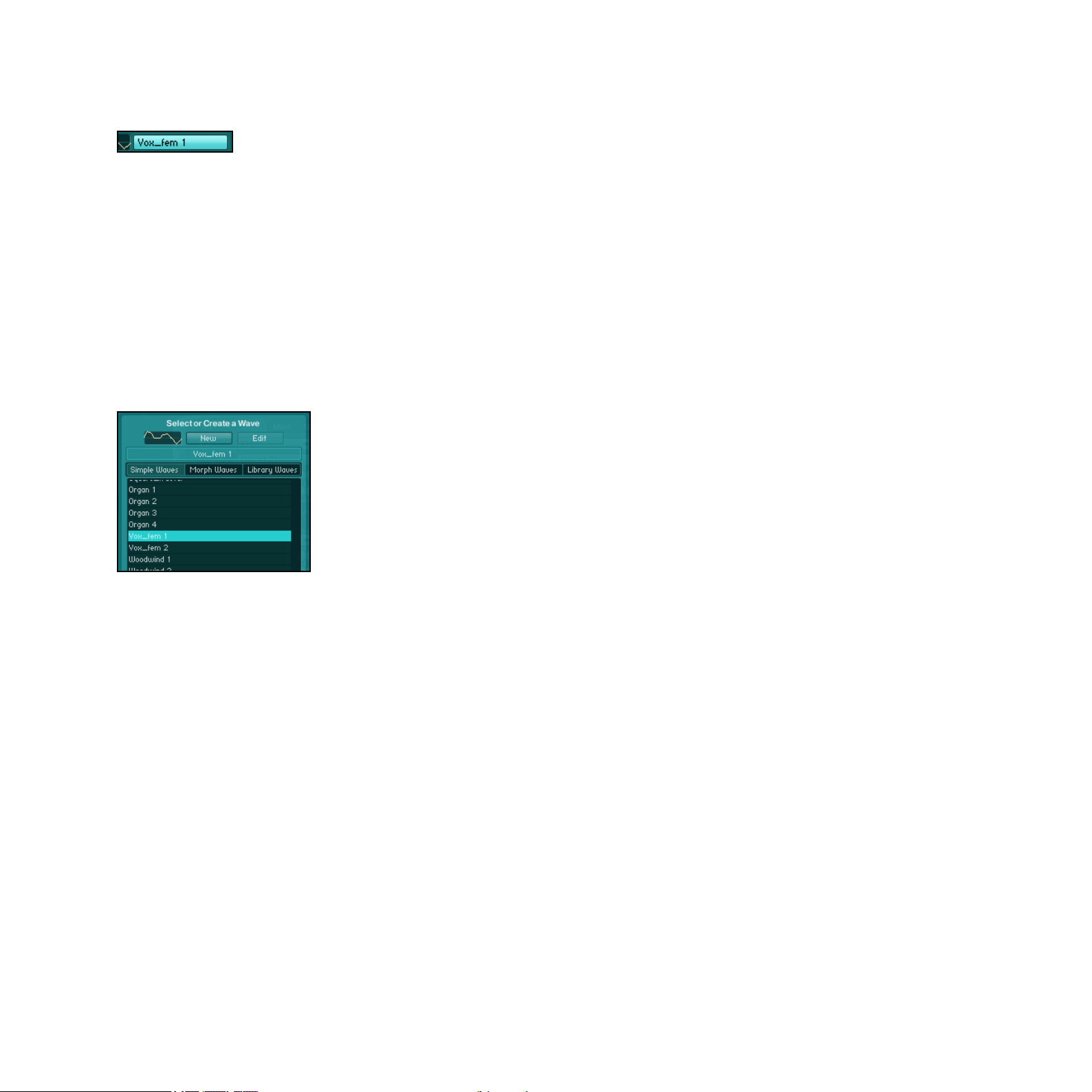
5.3.1 Waveform Selector and Waveform Selection dialog
Waveform Selector
The Waveform Selector is available for all oscillator modes based on a wavetable. It allows you
to choose the Waveforms for the oscillators in ABSYNTH5. This is not only the case for the
various oscillators within the Patch Window, but also for all other functions in ABSYNTH5
using Waveforms as a foundation. For example, you will also nd the Waveform Selector in
an identical form in the LFO Window and in the LFO area of the Envelope Window.
A click on the Waveform Selector opens the so-called Waveform Selection dialog. This dialog
essentially contains a list of all available Waveforms:
The Waveform Selection dialog
Using the three buttons above the list, you can switch it between three categories of
Waveforms:
•
Simple Waves are single cycle Waveforms that are read from a wavetable. This relates to
the tiny samples that contain one period of a particular Waveform. In this rubric, next to
the standard forms like Sine, Triangle, Saw and Square, you also nd instrumental and
atonal Waveforms.
• Morph Waves are Waveforms that use the function Wave Morph (see section 7.5 “Wave
Morph”). From a technical point of view, Morph Waves are two Waveforms saved in one
unit of data, which seamlessly blend (“morph”) with one another.
• Library Waves are the Waveforms from the Universal Library of ABSYNTH5.
ABSYNTH 5 Reference Manual – 45
Page 46

In order to display the Waveforms of a particular category in the list, click on the corresponding button at the top of the Waveform Selection dialog.
To load a Waveform into the module, click on its entry in the list. The new Waveform becomes
immediately active, so that the effects on the sound can be heard as soon as you press a
key on your MIDI keyboard. The small waveform display next to the Waveform Selector also
displays the new Waveform straightaway. When you have decided on a Waveform, click “OK”
at the bottom of the Waveform Selection dialog.
►
In order to create a new Waveform, select a Waveform in the list and click on the New
Wave button (labeled New), at the top of the dialog:
→
A new Waveform based on the selected Waveform is generated and loaded into the Wave
Window. ABSYNTH 5 switches the current Window automatically to this Wave Window.
Remember that your work does not affect the original Waveform, but rather produces an
!
independent copy of it.
►
If you want to work on a Waveform that already exists, click on the Edit Wave button
(labeled Edit), at the top of the dialog.
→ ABSYNTH 5 loads the selected Waveform automatically into the Wave Window and
switches the Window in an according fashion.
You can only work on Waveforms that you created yourself (by clicking on the New Wave button in the past). You cannot modify the Factory Waveforms.
The chapter 7, “Wave Window”, gives you all details about working with the Wave Window.
ABSYNTH 5 Reference Manual – 46
Page 47

5.3.2 Frequency Menu and Frequency Control
Frequency menu in Trans mode
All oscillators can be set to react to incoming notes in various ways. Thys are kency modes.
Using anel’s Frequency menu and its companion thcy control sitting at its right, you can to
choose from the following Frequency modes:
•
Trans: The oscillator follows the pitch of the played note. The Frequency control deter-
mines the transposition in semitones. For example, setting the Frequency control to 1.5
will lead to a transposition of one and a half tone compared with the pitch of the played
note. The Frequency control has a resolution of 1/1000 of a halftone.
• Ratio: Tranposes the oscillator according to a frequency ratio (for example along the har-
monic sequence: 2 corresponds with a transposition of 12 halftones, 3 with a transposition of 19 halftones, etc.). This mode is especially useful when using frequency modulation and ring modulation.
•
Hz: Fixed pitch in Hertz. In this mode, also useful for frequency and ring modulation, the
oscillator ignores the pitch of the note played. Rather, the pitch of the oscillator does not
reacts to information like pitch bend or to signals coming from an LFO, but it can be
controlled via an Envelope.
•
Note: Fixed pitch corresponding to a selectable MIDI note. This mode is similar to the
Frequency Mode Hz, but is more appropriate when you want to use the oscillator on a
note-bound frequency (e.g. 60.5 = C3 plus a quarter-ton).
You can switch between the Frequency mModes Hz and Notes to display the exact fre-
%
quency of particular notes.
ABSYNTH 5 Reference Manual – 47
Page 48

5.3.3 Anti-Alias Switch
Anit-Alias switch
The Anti-Alias switch enables you to smooth peaks in various situations. Anti-aliasing provides
a smooth, almost analog sound. In order to turn on the anti-aliasing, click on the Anti-Alias
switch (the small steps/ramp button).
When the symbol displays little steps, the anti-aliasing function is off. A smooth line (ramp)
indicates that the function is on for this oscillator.
This makes a big difference with high frequencies. Without it, you would probably hear something called “fold back” – a not so subtle form of digital distortion that makes high tones sound
coarse or harsh (two properties that are sometimes desired, but usually not). Anti-aliasing
reduces the fold back to a large extent. Keep in mind that when an oscillator smoothes over
edges, it uses more CPU power. If you can discern no difference between enabled and disabled anti-aliasing, it would be best if you left it turned off.
For compatibility reasons, all patches created with ABSYNTH 1 are opened with the
!
Channels have the Anti-Alias switch enabled and some others have not.
Anti-Alias switch deactivated. With ABSYNTH 5, you can create patches for which some
ABSYNTH 5 Reference Manual – 48
Page 49

5.3.4 Phase Inverter
The Phase Inverter is available in all Oscillator‘s synthesis modes based on a wavetable. When
activated, it simply inverses the phase of the signal generated by the oscillator – in other
terms, it shifts the phase by 180°.
5.4 Oscillator Module
Oscillator module
The three Oscillator modules are the only sound sources in ABSYNTH 5. All other modules
only modify the sounds produced by the Oscillators. If none of the Oscillators are turned on,
you will hear no sound, and none of the other modules can be activated. Accordingly, the
modules of a Channel are only available when its Oscillator is active.
The Oscillators can run in numerous different operating modes, which primarily differentiate
by their synthesis process. In the following sections, you will learn more about these individual
operating modes. But we will rst present the general layout and common features for all
Oscillators.
The Oscillator can be inserted into the rst Module Slot at the top of each Channel A, B or
C of the Patch Window.
To activate an Oscillator module, do the following:
► Click on the extended left margin of the desired Module Slot to activate it.
ABSYNTH 5 Reference Manual – 49
Page 50

5.4.1 Oscillator‘s Panels and Tabs
The Oscillator always provides you with the following panels: Main, Mod, and Uni (albeit occasionally inactive). Click on a tab to activate the corresponding panel.
Oscillator panels
Main Panel
The Main panel contains all the parameters dealing with the main oscillator of the Oscillator
module. The most important element of this Main panel is the Synthesis menu, which denes
the type of synthesis performed for the main oscillator. The synthesis modes available in this
Synthesis menu are sorted into three groups (separated by horizontal lines):
•
Wavetable synthesis (Single, Double, FM, Ringmod, Fractalize, Sync Granular): The
Oscillator produces signals based on monocyclic Waveforms.
• Sampling (Sample, Granular): The Oscillator produces signals based on a sample.
•
External audio signal (Audio In): The Oscillator delivers an audio signal, which itself comes
from an external source.
The other parameters of this panel depend on the selected synthesis mode. We will detail
them in the sections describing each individual synthesis mode below.
Mod Panel
The Mod panel (Modulation) holds all parameters of the modulation oscillator. The available
parameters depend on the synthesis mode selected in the Main panel. Information about
these specialized parameters can be found in the sections describing each individual synthesis
mode below.
ABSYNTH 5 Reference Manual – 50
Page 51

Uni Panel
The Uni panel (Unisono) allows you to implement multi-voicing at the oscillator level.
Available for the synthesis modes Single, Double, FM, Ringmod and Fractalize, the Uni panel
provides you with following parameters:
• NumVoices: Sets the number of voices produced by each note played. The highest value is 8.
•
Trans: Controls the amount of detuning (in semitones) between the original voice and the
additional voices. This parameter affects the sound only if the Num Voices value is
larger than 1 – in other words, if there are some additional voices to detune.
• RandTrans: Adds a quota of random detuning (upwards and downwards) in half-tones.
The function Unisono allows you to “stack” voices quickly and produce fuller, stronger sounds.
If you raise the Num Voices value by 1, a new voice will be added and mixed with the output
signal of the Oscillator.
The Trans value determines what interval you desire between the original sound and the tone
pitch of the additional voices. Even-numbered additional voices are transposed downwards,
odd-numbered voices upwards.
If, for example, you were to set the value for Num Voices at 3 and the value for Trans at
%
deeper and by another one transposed one semitone higher. If you raise the number of voices to 4,
a new (even-numbered) voice will be attached which is a half-tone under the last even-numbered
voice (that is, two half-tones under the basic tone). If you were to set the value for num voices at
5, a new (odd-numbered) voice would be attached, which would be one half-tone lower than the
last odd-numbered voice.
1, every note would be accompanied by a voice that has been transposed one semitone
ABSYNTH 5 Reference Manual – 51
Page 52

The parameter Rand Trans produces accidental detuning of the voices with every note in the
sequence. Subtly put to work, with a low value for Num Voices, Rand Trans can produce the
effect of a sloppy or imprecise intonation (in order, for example, to imitate a string instrument without tension or to give atonal percussion sounds some natural variation). You can
get some unpredictable and exciting results by playing around with different selections ! In
the operating modes Sync Granular, Sample, Granular and Audio In, the Unisono function is
not available and the Uni tab and panel are inactive.
5.4.2 Oscillator’s Edit Menu
The Edit menu, located in the upper left-hand corner of the Oscillator, is available for all kinds
of Oscillators. It provides the following options:
• CopyOscil: Copies the settings of the selected Oscillator to the clipboard.
•
CopyChannel: Copies to the clipboard the settings of all active modules in that Channel.
•
PasteOscil: Places the settings stored in the clipboard (via the command Copy Oscil) into
the selected Oscillator.
• PasteOscilandEnvelopes: Places the settings stored in the clipboard (via the command
Copy Oscil) into the selected Oscillator. Any Envelopes linked to the Oscillator are also
placed within the Oscillator.
•
PasteChannel: Places the Channel settings stored in the clipboard into the current Channel.
•
LoadOscilTemplate: Opens a dialog allowing you to choose Oscillator settings to load
from a list of predened Oscillator Templates. Click on the desired entry in the list and
click “OK” to load that Template.
•
LoadChannelTemplate: Opens a dialog allowing you to choose Channel settings to load
from a list of predened Channels Templates. Click on the desired entry in the list and
click “OK” to load that Template.
•
SaveOscilTemplate: Allows you to save the current Oscillator settings as a Template in
the Universal Library. In the dialog that opens, choose the name and saving location for
the Template, then click then on “OK” to save the Template.
ABSYNTH 5 Reference Manual – 52
Page 53

•
SaveChannelTemplate: Allows you to save the current Channel settings as a Template in
the Universal Library. In the dialog that opens, choose the name and saving location for
the Template, then click then on “OK” to save the Template.
• MutateOscil: Applies a Mutation to that particular Oscillator.
• RetryMutateOscil: Retries the Mutation for that particular Oscillator.
For the last two entries, the Mutation settings are those dened in the Browser’s Mutaton
section (see section 11.3, “Mutator”, for more on this).
5.4.3 Single Mode
Oscillator in Single mode
In the Single mode, a single main oscillator is active.
The Main panel contains all parameters controlling the main oscillator:
•
Synthesismenu: Selects the desired synthesis process (see section 5.4.1 “Oscillator’s
Panels and Tabs” above for details).
•
WaveformSelector: A click on the Waveform Selector opens the Waveform Selection dialog where you can select the Waveform for the Oscillator (see section 5.3.1, “Waveform
Selector and Waveform Selection dialog”, above for details).
•
Anti-Aliasswitch: Turns the anti-aliasing on and off (see section 5.3.3 “Anti-Alias Switch”
above for details).
•
FrequencymenuandFrequencycontrol: Enables you to enter the oscillator’s frequency as
a transposition of the played note (Trans), as a relationship (Ratio) with the played note,
as a xed Frequency (Hz) or via a xed MIDI note (Note). See section 5.3.2, “Frequency
Menu and Frequency Control”, above for details.
ABSYNTH 5 Reference Manual – 53
Page 54

• PhaseSyncswitch: Setting the Phase Sync switch to Phase will reset the phase of the oscil-
lator with every incoming MIDI note. When the Phase Sync switch is set to Free, the oscillator
will not be reset. When only one oscillator is active and you have set one voice in the Uni
panel, the mode Free has almost no effect. When you have a higher Unisono number of
voices or multiple active oscillators, every note leads to an audible change in the sound.
•
Phasecontrol: Sets the phase of the Oscillator. The effect is only audible if a second
Oscillator is active. This parameter is useful when using integer values for frequency ratios
between carrier and modulator, as it is the case in FM.
5.4.4 Double Mode
Oscillator in Double mode
In Double mode, a pair of oscillators – consisting of the Main oscillator and the Mod oscillator – is active. The signals of the two oscillators are mixed.
On the Main panel, you will nd the same parameters as in Single mode. For more info on
these parameters, please refer to the section 5.4.3, “Single Mode”, above.
On the Mod panel, the following parameters are available:
•
Balancecontrol: Controls the balance between the oscillators Main and Mod within the
Oscillator’s output signal.
•
WaveformSelector: This opens a dialog where you can choose the Waveform for the Mod
oscillator (see section 5.3.1, “Waveform Selector and Waveform Selection dialog”, above
for details).
•
FrequencymenuandFrequencycontrol: Enables you to enter the oscillator’s frequency as
a transposition of the played note (Trans), as a relationship (Ratio) with the played note,
as a xed Frequency (Hz) or via a xed MIDI note (Note). See section 5.3.2, “Frequency
Menu and Frequency Control”, above for details.
ABSYNTH 5 Reference Manual – 54
Page 55

•
Phasecontrol: Sets the phase of the Oscillator. The effect is only audible if a second
Oscillator is active. This parameter is useful when using integer values for frequency ratios
between carrier and modulator, as is the case in FM.
An Oscillator in Double mode uses less CPU power than two Oscillators in Single mode.
%
5.4.5 FM Mode
Oscillator in FM mode
Frequency modulation was discovered in the late 1960’s by John Chowning and achieved
great popularity in the 1980’s through Yamaha’s DX7 synthesizer. Much has already been
written about FM synthesis so we will not go into detail here.
In FM mode, the Mod oscillator modulates the frequency of the Main oscillator.
On the Main panel, you nd the same parameters as in Single mode. For more details, please
refer to the section 5.4.3, “Single Mode” above.
On the Mod panel, the following parameters are available:
• FMIndex: This determines the depth of the Frequency Modulation.
•
WaveformSelector: Clicking the Waveform Selector allows you to choose the Waveform
for the oscillator (see section 5.3.1, “Waveform Selector and Waveform Selection dialog”,
above for details).
•
FrequencymenuandFrequencycontrol: Enables you to enter the oscillator’s frequency as
a transposition of the played note (Trans), as a relationship (Ratio) with the played note,
as a xed Frequency (Hz) or via a xed MIDI note (Note). See section 5.3.2, “Frequency
Menu and Frequency Control”, above for details.
ABSYNTH 5 Reference Manual – 55
Page 56

•
Phasecontrol: Sets the phase of the Oscillator. The effect is only audible if a second
Oscillator is active. This parameter is useful when using integer values for frequency ratios
between carrier and modulator, as it is the case in FM.
5.4.6 Ringmod Mode
In Ringmod mode, the signals from the main oscillator and the mod oscillator are multiplied
with one another.
On the Main panel, you nd the same parameters as in Single mode. For more details, please
refer to the section 5.4.3, “Single Mode”, above.
On the Mod panel, the following parameters are available:
•
Balancecontrol: Controls the balance between the oscillators Main and Mod within the
Oscillator’s output signal.
•
WaveformSelector: Click on the Waveform Selector to open a dialog where you can choose
the Waveform for the oscillator (see section 5.3.1, “Waveform Selector and Waveform
Selection dialog”, above for details).
•
FrequencymenuandFrequencycontrol: Enables you to enter the oscillator’s frequency as
a transposition of the played note (Trans), as a relationship (Ratio) with the played note,
as a xed Frequency (Hz) or via a xed MIDI note (Note). See section 5.3.2, “Frequency
Menu and Frequency Control”, above for details.
ABSYNTH 5 Reference Manual – 56
Page 57

5.4.7 Fractalize Mode
Oscillator in Fractalize mode
Experienced ABSYNTH users will recognize the Fractalize mode as a real time version of the
function Fractalize available in the Transform menu of the Wave Window (which also functions
very similarly). In Fractalize mode, the selected Waveform is copied to itself, so that you can
see smaller elements of the Waveform that are similar to the image of the whole. You can use
the Fractalize mode to add overtones to a plain Waveform.
On the Main panel, you nd the same parameters as in Single mode. For more details, please
refer to the section 5.4.3, “Single Mode”, above.
On the Mod panel, the following parameters are available:
•
Iterations: With this parameter you can choose the number of similar repetitions that you
want of the same sound, and how much you want to deviate from the original Waveform.
The value area is between 2 and 7; higher values lead to more complex, lighter-sounding
sounds – and to a heavier CPU loads.
• Amount: With this you can dene the mixing relationship between the original waveform
and its copies.
•
Displace: With this parameter you can dene the shift of the copied area relatively to the
original Waveform: 0 corresponds to a position before the Waveform, 1 to a position after
the Waveform. With a value of 0.5, the area is directly central to the Waveform. If you
modulate this parameter with an LFO or an Envelope, interesting movements inside the
sound will result.
The function Fractalize in the Wave Window gives you an idea of what happens. Load a
%
nothing has happened. Choose the entry Fractalize from the Transform menu. Set Iterations to 2 and
Displace to 9. Slowly increase the value for Displace up to 25. You see how the waveform distends.
simple Waveform (such as a sine) into the Wave Window. Check under the Wave View: so far
Change the value for Iterations; the higher the value, the more dislocated the Waveform becomes.
ABSYNTH 5 Reference Manual – 57
Page 58

In Fractalize mode, the Uni panel contains a somewhat different combination of parameters
than in the modes Single, Double, FM and Ringmod: Trans and Rand Trans work in exactly
the same way as in the other modes. But instead of the parameter Num Voices, the parameter Iterations operates a similar function in setting the number of voices in Fractalize mode.
Fractalize mode works particularly well with Waveforms that contain limited, yet strong
%
the right Waveform you can achieve interesting, formant-style effects. With harmonically dense
Waveforms (e.g. the saw from the ABSYNTH5 Waveform Library) the effect is not as striking.
harmonics: you will see new overtones emerge around the basic harmonics. By choosing
5.4.8 Sync Granular Mode
The Sync Granular mode works along the same lines as the Granular mode (see section 5.4.10,
“Granular Mode”, below for more details): It divides a Waveform into the smallest parts (the so-
called “grains”) and then brings these parts back together. The difference between the granular
synthesis processes in ABSYNTH 5 relates to the input material that is used: In Granular mode,
the grains are taken from a sample, whilst the Sync Granular mode uses a Waveform from the
Library. In Sync Granular Mode, you can take your own Waveforms or an existing Waveform
from the Library, tear it apart, and then put it back together again in a new way.
Before putting the grains back together through a process known as resynthesis, you can
inuence the grain “cloud”: You can change the frequency of the grains, change the Density
control value to determine how individual grains overlap, and use the parameter Scatter to
manipulate the level of diffusion of the grain cloud.
These options allow you to create very effective sounds and, for example, convincingly simulate the blowing sound of a wind instrument such as a pipe or ute.
On the Main panel, you nd the same parameters as in Single mode. For more details, please
refer to the section 5.4.3, “Single Mode”, above.
ABSYNTH 5 Reference Manual – 58
Page 59
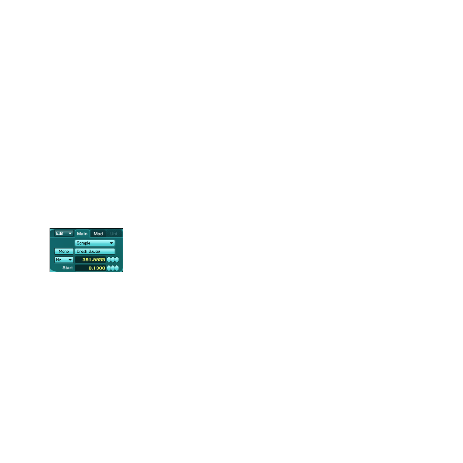
On the Mod panel, the following parameters are available:
•
Balancecontrol: Here you set the mix relationship between the original Waveform and the
Waveform produced by resynthesis. With a value of 0 only the original Waveform can be
heard, with a value of 1 only the resynthesized Waveform.
•
Denscontrol: Here you dene the density of the grain cloud by setting how individual
grains overlap. The values ranges from 3 to 8; small values give a raw sound, higher
value a more polished sound.
• Scattercontrol: With this you can control the diffusion, that is, the accidental scattering
of the grain cloud.
•
FrequencymenuandFrequencycontrol: Enables you to enter the oscillator’s frequency as
a transposition of the played note (Trans), as a relationship (Ratio) with the played note,
as a xed Frequency (Hz) or via a xed MIDI note (Note). See section 5.3.2, “Frequency
Menu and Frequency Control”, above for details.
5.4.9 Sample Mode
Oscillator in Sample mode
The Oscillator module rules two sample-based modes: Sample and Granular. These modes
make it possible for you to use ABSYNTH5 as a sampler, playing back previously uploaded
sound data in the WAV or AIFF format.
The basic control is the same in both modes, so the following instructions on the Sample
mode also apply to the Granular mode described in the next section.
In contrast to conventional sampling instruments, ABSYNTH lacks the usual functions such as
key mapping, velocity layering or AKAI import. Unlike the conventional samplers, ABSYNTH’s
emphasis is not on the realistic reproduction of sampled instruments, but rather the creative
possibilities that sample-supported synthesis provides.
ABSYNTH 5 Reference Manual – 59
Page 60

All three Oscillator modules can load a sample; in a single Sound you can use up to three
different samples.
Before you experiment with ABSYNTH’s sampling possibilities, you should rst load a
%
then open the Patch Window.
In order to load a Sample into an Oscillator module, do the following:
1. Choose the Sample entry from the Synthesis menu. On the Sample Selector below, you
will see (none) displayed:
2.
Click on this Sample Selector. This activates a dialog that allows you to choose a sample
to open on your hard drive.
3. Choose a sample le that you would like to load and click on “Open.”
neutral patch. Choose the New Sound option in the File menu of the Navigation Bar, and
→ The Sample is now loaded, and the Sample Selector displays its name.
ABSYNTH 5 can read AIFF and WAV data (stereo or mono) ranging from 16 to 32 bit and
any sampling rate.
In Sample mode, the Main panel holds the following parameters:
• SampleSelector: See description above.
•
Mono/Stereoswitch: Stereo samples can be reproduced in stereo or mono, depending on
your liking. If you have loaded a stereo sample, you can use the Mono/Stereo switch to
switch between mono and stereo reproduction. If your sample cannot be switched to
stereo, then it is a mono sample.
•
FrequencymenuandFrequencycontrol: Enables you to enter the oscillator’s frequency as
a transposition of the played note (Trans), as a relationship (Ratio) with the played note,
as a xed Frequency (Hz) or via a xed MIDI note (Note). The Sample will be reproduced
with its original speed when the MIDI Note C3 is played. Lower notes produce a slower,
lower sound, while higher notes sound higher and faster. See section 5.4.2, “Oscillator’s”,
above for more info on these controls.
ABSYNTH 5 Reference Manual – 60
Page 61
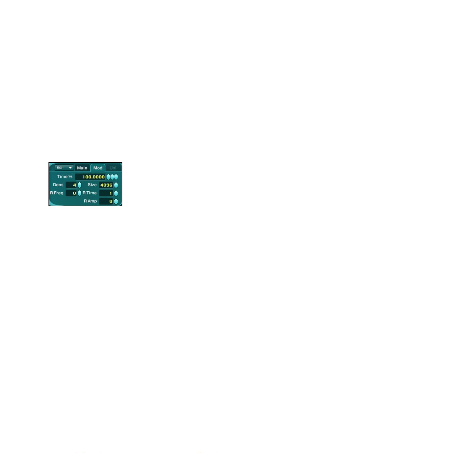
•
Startcontrol: Denes the starting point of the playback within the Sample relatively to
the overall sample duration.
The Mod panel offers you one parameter:
•
PlayModemenu: This menu lets you choose from three playback modes. If No Loop is
selected, the sample is played once (good for percussion sounds). If Loop All is selected,
the entire sample is played as a loop (this works best if you edit the loop beforehand to
create a seamless loop). If Loop Edit is selected, two additional parameters allow you to
adjust the start point and end point of the loop.
5.4.10 Granular Mode
Oscillator in Granular mode
The Granular mode also uses a sample as basis for the sound creation. However, this mode
divides the sample into many small grains, each containing a tiny fragment of the sound. In
this way you can independently control the sample’s pitch and duration. In Granular mode,
the duration of a Sample remains the same over the entire keyboard, whilst the notes determine the pitch.
On the Main panel, you nd the same parameters as in Sample mode. For more details,
please refer to the section 5.4.9, “Sample Mode”, above.
The Mod panel contains following parameters:
•
Time%: Determines the playback speed of the sample. 50% corresponds to half of the
original speed while 200% doubles the speed of your sound. If you set this value to zero,
the Sample for that length of time will “freeze.” When you have frozen a sample, you can
use the parameter Start control on the Main panel to establish when exactly it should freeze.
ABSYNTH 5 Reference Manual – 61
Page 62

•
Dens: Determines the number of grains played simultaneously. Here you can set values
between 1 and 8. A lower value produces a thinner sound, whereas a value of 8 produces a dense granular cloud. Remember: Big Dens values use a lot of CPU power!
•
Size: Determines the length of every grain (in samples – here in its signal processing
meaning!). Smaller values are good for percussive sounds, whereas higher values function
well for pad-like sounds or string instruments. Bear in mind that small values tend to
conceal the character of the sample and produce typical granular artifacts in the form of
noise. The maximum value for the parameter is 9,999 samples (approximately 225ms
at a sampling rate of 44.1kHz).
•
RTime: Denes the randomness of the grains’ playback speed. Zero corresponds to no
randomness during grain playback, whilst 100 means that the grains are played completely at random – within the time window dened by the Size parameter.
•
RFreq: Changes the pitch of individual grains randomly. Zero means no randomness,
whereas 100 assumes complete randomness concerning pitch.
•
RAmp: Changes the amplitude (“loudness”) of the individual grains randomly. A value of
zero means no randomness whilst 100 means complete randomness.
5.4.11 Audio In Mode
Oscillator in Audio In mode
In the operating mode Audio In, the Oscillator does not produce the signal itself, but rather
transmits incoming audio signals to its output. That makes it possible for any audio signal to
work with the other modules in ABSYNTH 5 in real time. ABSYNTH 5 can thus be used as an
effect and work with live audio signals being played elsewhere. You can also load ABSYNTH
5 as an effect plug-in in your audio MIDI sequencer and let it process any audio track.
ABSYNTH 5 Reference Manual – 62
Page 63

When you have created a Sound in which some Oscillators work in the Audio In mode,
%
appears in the relevant search results within the Browser Window.
You can access all of the Audio In parameters through the Main panel:
•
Mono/Stereoswitch: You can choose between mono and stereo signals. If you choose
mono, you will only see one Input menu below. If you choose stereo, then a second,
identical Input menu appears.
•
Levelcontrol: Increases or attenuates the input signal level. At the default value of 0dB,
the signal passes through the input stage unchanged.
•
Inputmenu: Chooses from one of six possible audio inputs, which you can congure in
the Audio and MIDI Settings dialog of the stand-alone version (in the File menu of the
Application Menu Bar).
!
means that you do not hear audio signals from external sources unless ABSYNTH5 has received
MIDI notes and used them to trigger the Envelopes!
you should assign this Sound to the category “Effect” in the Attribute Window, so that it
External audio signals run through ABSYNTH5’s signal path in exactly the same way as
internally created signals and so are also inuenced by ABSYNTH5’s Envelopes. This
5.5 Filter Module
The Filter module provides a number of lters to work with. You can work on the frequency
spectrum of a sound by, for example, emphasize the high frequencies while reducing the
lower frequencies.
5.5.1 General Functioning
The Filter modules can be inserted in any Module Slot of the Patch Window, except the rst
Slot in each Channel A-C (these are reserved for Oscillator modules) and the last Slot in the
Master Channel (reserved for the Effect module).
ABSYNTH 5 Reference Manual – 63
Page 64

To activate a Filter module, do the following:
1.
Click on the extended left margin on a Filter, Modulator or Waveshaper Module Slot to
activate it.
2.
Choose one of the lter types from the Type menu (the rst and biggest group in the
menu).
5.5.2 Filter’s Panels and Tabs
Like all other modules, a Filter module can have up to three panels organizing the various
module parameters. Each panel can be called by clicking on the corresponding tab at the
top of the module.
The available panels depend on the type of lter. You will nd a complete list of available
panels in the module-specic sections below. But we can already give here two basic rules
for these panels:
• All lter types but the Cloud offer a Main panel as rst panel, holding the main param-
eters for that lter type.
•
The lter types LPF 2 Pole, LPF 4 Pole, LPF 8 Pole, Allpass 2, Allpass 4, Allpass 8 and
Supercomb have an additional FB panel controlling the new feedback loop introduced in
ABSYNTH5 for these lters (see next section).
5.5.3 Feedback Loop and Feedback Panel
ABSYNTH 5 introduces a new functionality to some of its Filter modules: a feedback loop.
This feedback loop allows you to send a portion of the lter’s output back to its own input…
without forgetting to further process the signal on the way! The feedback loop is available
for following lter types: LPF 2 Pole, LPF 4 Pole, LPF 8 Pole, Allpass 2, Allpass 4, Allpass
8 and Supercomb.
For all of these lter types, the feedback loop settings are located on the Feedback panel
(labeled FB), next to the Main panel:
ABSYNTH 5 Reference Manual – 64
Page 65

A typical Feedback panel
Worth to note is that the feedback loop is built inside the resonance loop of the Filters.
!
parameter found on the Main panel of each Filter (except for the Supercomb, where it is called
Feedback control).
The panel’s upper line always holds the two following parameters:
•
Anti-Aliasswitch: Enables/disables the anti-aliasing, which smoothes peaks in the feedback
loop. Click on the Anti-Alias switch – the small steps/ramp button – to change its state
(more info on the Anti-Alias switch can be found in the section 5.3.3, “Anti-Alias Switch”).
•
FeedbackModemenu: This menu allows you to select the desired feedback mode. If
Normal is selected, the feedback loop is deactivated. The three other modes available in
the Feedback Mode menu are described in the following sections.
Waveshape Feedback Mode
Therefore, the amount of signal sent in the feedback loop is also affected by the Resonance
When this mode is selected in the upper Feedback Mode menu of the Feedback panel, the
signal in the feedback loop is processed by a mini-Waveshaper. Hence, the parameters in the
lower part the Feedback panel are very similar to those of the Waveshaper module.
The few differences are listed here:
•
A Phase Inverter appears next to the Waveform Selector (for more info on the Phase
Inverter, see section 5.3.4, “Phase Inverter”).
•
The In dB and Out dB controls from the Waveshaper module are here replaced with an
Amount control, which denes the proportion of signal processed by the Waveshaper.
The rest is exactly the same as in the Waveshaper. Please refer to section 5.7, “Waveshaper
Module”, for more info on its principle, functioning and parameters.
ABSYNTH 5 Reference Manual – 65
Page 66

Freqshift Feedback Mode
When this mode is selected in the upper Feedback Mode menu of the Feedback panel, the
signal in the feedback loop is processed by a mini-Freqshifter. Hence, the parameters in the
lower part the Feedback panel are very similar to those of its big brother, the Modulator in
Freq Shift mode.
The few differences are listed here:
•
An Anti-Alias switch appears at the top left corner (for more info on the Anti-Alias switch,
see section 5.3.3, “Anti-Alias Switch”).
• The Feedback control from the Modulator module in Freq Shift mode was replaced with
a Mix control, which denes the proportion of signal processed by the Freq Shifter.
The rest is exactly the same as in the Modulator module in Freq Shift mode. Please refer to
section 5.6.3, “Frequency Shift”, for more info on its principle, functioning and parameters.
Ringmod Feedback Mode
When this mode is selected in the upper Feedback Mode menu of the Feedback panel, the
signal in the feedback loop is processed by a mini-Modulator module in Ringmod mode. Hence,
the parameters in the lower part the Feedback panel are very similar to those of its big brother.
The few differences are listed here:
•
An Anti-Alias switch appears at the top left corner (for more info on the Anti-Alias switch,
see section 5.3.3, “Anti-Alias Switch”).
•
The Balance control from the Modulator module in Ringmod mode was replaced with a
Mix control, which denes the proportion of signal processed by the Ring Modulator.
The rest is exactly the same as in the Modulator module in Ringmod mode. Please refer to
section 5.6.2, “Ring Modulation”, for more info on its principle, functioning and parameters.
ABSYNTH 5 Reference Manual – 66
Page 67

5.5.4 Lowpass
Lowpass Filter LPF 2 Pole
The lowpass lters weaken the signal above an adjustable cutoff frequency. The slope gradient
of the signal attenuation is given in dB per octave. A value of -12dB/octave means that the
lter dampens the signal by 12dB more at one octave higher. Other values for slope gradient are -6dB and -24dB.
The slope gradient can also be referred to as the n-pole (this is the most usual case with
synthesizers and other electronic sound generators). Most of the time, n stands for an even
number between 2 and 8. This data can be easily translated into the dB/octave schema if you
remember that every lter pole corresponds to a steepness of -6dB/octave. So a 1-pole lter
has a gadient of -6 dB/octave, a 2-pole lter dampens the signal by -12 dB/octave, and so on.
As a consequence, ABSYNTH 5’s lowpass lter LPF 2 Pole and LPF -12dB have for example
the same slope gradient. The same applies to the LPF 4Pole and LPF -24dB. Yet they sound
different because of their different internal constructions: The rst three lters in the list
below have a softer, rounder character, whereas the lters in the second group sound rougher
and more aggressive.
The following lowpass lters are available in the Type menu:
• LPF2Pole: 2-pole lowpass lter with resonance control and analog design.
• LPF4Pole: 4-pole lowpass lter with resonance control and analog design.
• LPF8Pole: 8-pole lowpass lter with resonance control and analog design.
• LPF-6dB: 1-pole lowpass lter with resonance control.
• LPF-12dB: 2-pole lowpass lter with resonance control.
• LPF-24dB: 4-pole lowpass lter with resonance control.
ABSYNTH 5 Reference Manual – 67
Page 68

Main Panel
All lowpass lters in ABSYNTH 5 contain the following parameters on their Main panel:
• FrequencycontrolandFrequencymenu: The Frequency control allows you to set the cut-
off frequency in semitones (Trans) or in Hertz (Hz), upon the selection in the nearby
Frequency menu.
• Resonancecontrol: Sets the resonance at the cutoff frequency.
•
Dampingcontrol: Allows you to balance out the volume level. If the signal level at the
lter output seems too weak, increase this value.
Feedback Panel
Furthermore, the lter types LPF 2 Pole, LPF 4 Pole and LPF 8 Pole are equipped with a
feedback loop. Its function and parameters are detailed at section 5.5.3 “Feedback Loop
and Feedback Panel” above.
5.5.5 Highpass
Highpass Filter HPF -12dB
Highpass lters permit all frequencies above a cutoff frequency and suppress the frequencies
below it. Their remaining functions are identical to those described for the lowpass lters in
the section 5.5.4, “Lowpass”, above.
The following highpass lters are available in the Type menu:
• HPF-6dB: 1-pole highpass lter.
• HPF-12dB: 2-pole highpass lter with resonance control.
ABSYNTH 5 Reference Manual – 68
Page 69

Main Panel
The highpass lters in ABSYNTH 5 contain the following parameters on their Main panel:
• FrequencycontrolandFrequencymenu: The Frequency control allows you to set the cut-
off frequency in semitones (Trans) or in Hertz (Hz), upon the selection in the nearby
Frequency menu.
• Resonancecontrol (HPF -12dB only): Sets the resonance at the cutoff frequency.
5.5.6 Allpass
Allpass lter Allpass 4
Allpass lters allow all frequencies to pass through the output with similar strength, but modify
the phase of the signal. Allpass lters are useful for creative ltering as they can easily produce
phasing or resonating effects. With allpass lters, the number of poles dene the number of
peaks in the frequency spectrum of the ltered signal. With high resonance values, an 8-pole
allpass lter can sound very similar to a bell.
The following allpass lters are available in the Type menu:
• Allpass2: 2-pole allpass lter.
• Allpass4: 4-pole allpass lter.
• Allpass8: 8-pole allpass lter.
Main Panel
Every allpass variant shares the following two parameters on the Main panel:
• FrequencycontrolandFrequencymenu: The Frequency control allows you to set the cut-
off frequency in semitones (Trans) or in Hertz (Hz), upon the selection in the nearby
Frequency menu.
• Resonancecontrol: Sets the resonance.
ABSYNTH 5 Reference Manual – 69
Page 70

Feedback Panel
Furthermore, the allpass lters are equipped with a feedback loop. Its function and parameters
are detailed at section 5.5.3, “Feedback Loop and Feedback Panel”, above.
5.5.7 Bandpass
Bandpass Filter BPF
Bandpass lters combine a highpass and a lowpass lter: they dampen all frequencies that
lie outside a particular frequency range dened by two cutoff frequencies (or by a middle
frequency and a bandwidth). This means that this particular frequency range is allowed to
pass through, whilst lower and higher frequencies outside the range are suppressed.
Main Panel
ABSYNTH 5’s bandpass lter BPF has the following parameters:
•
FrequencycontrolandFrequencymenu: The Frequency control allows you to set the
middle frequency in semitones (Trans) or in Hertz (Hz), upon the selection in the nearby
Frequency menu.
•
Qcontrol: Sets the bandwidth of the lter around the middle frequency. Its values go from
0 to 1000Hz.
• Dampingcontrol: Allows you to balance out any level uctuations introduced by the lter
(in dB).
ABSYNTH 5 Reference Manual – 70
Page 71

5.5.8 Notch
Band Elimination Filter (Notch)
Notch is a band rejection lter with resonance. Band Reject lters work in the opposite fashion
as bandpass lters: they only weaken frequencies within a particular frequency range, dened
by two cutoff frequencies on both sides (or by a middle frequency and a bandwidth). Higher
and lower frequencies can pass through unhindered.
Main Panel
The Notch Filter has the following parameters:
•
FrequencycontrolandFrequencymenu: The Frequency control allows you to set the
middle frequency in semitones (Trans) or in Hertz (Hz), upon the selection in the nearby
Frequency menu.
•
Resonancecontrol: This control (labeled Res) allows you to adjust the resonance of the
lter.
• B-widthcontrol: Sets the bandwidth of the lter around the middle frequency. Its values
is measured in octaves.
ABSYNTH 5 Reference Manual – 71
Page 72

5.5.9 Comb
Comb Filter
Comb lters change the sound by delaying the signal by a few milliseconds and then mixing
the delayed signal with the original. As a result, the level of certain frequencies may be raised
or attenuated in the ltered signal.
Effects such as the phaser and the anger use this phenomenon. By modulating the Comb’s
%
Main Panel
The Comb Filter has the following parameters:
parameters, you can quickly produce a nice anging effect.
• FrequencycontrolandFrequencymenu: The Frequency control allows you to set the cut-
off frequency in semitones (Trans) or in Hertz (Hz), upon the selection in the nearby
Frequency menu.
•
Feedbackcontrol: Sets the amplication factor for the delayed signal. Higher values induce
steeper frequency peaks/cancellations.
• Dampingcontrol: Allows you to balance out any level uctuations introduced by the lter
(in dB).
ABSYNTH 5 Reference Manual – 72
Page 73

5.5.10 Supercomb
Supercomb Filter
The Supercomb lter is a new Filter type introduced in ABSYNTH 5. Basically, it is a Comb
Filter equipped with a feedback loop and a tonal control borrowing characteristics from the
Resonators and Pipe Effects. For more info on the basic functioning of the Comb lter, please
refer to the previous section 5.5.9, “Comb”.
In order to control the additional capabilities of the Supercomb lter compared to those of
the Comb lter, the Supercomb provides you with three panels:
• The Main panel is the same as the Comb’s Main panel.
• The Feedback panel contains the parameters related to the feedback loop.
• The Tone panel holds parameters controlling the tone of the lter.
Main Panel
The Supercomb’s Main panel offers the same parameters as the usual Comb lter – again,
please refer to the previous section 5.5.9, “Comb”, where they are described.
Feedback Panel
The function and parameters of the Feedback panel are detailed at section 5.5.3, “Feedback
Loop and Feedback Panel”, above.
ABSYNTH 5 Reference Manual – 73
Page 74

Tone Panel
The Supercomb’s Tone panel contains following parameters:
•
ToneModemenu: selects from a set of resonance modes. The higher the feedback is turned
up, the more pronounced the effect is. The Tone mode changes the color of the decay.
• Tonecontrol: This controls affects the sound differently according to the mode selected
in the Tone Mode menu above. It is not available for the mode Raw.
• HPcontrol: Low frequency damping. Low frequencies decay faster as this control is turned up.
•
LPcontrol: High frequency damping. High frequencies decay faster as this is turned down.
This control is useful for a more natural resonance.
•
Positioncontrol: Controls the ratio of the delay taps (see 5.5.9, “Comb”, above). This
control changes the color of the comb lter.
Don’t hesitate to play with these controls to understand how they affect the sound. In
%
particular, modulate the Position parameter to get nice effects!
5.5.11 Cloud
Cloud Filter
The Cloud lter is another new lter introduced in ABSYNTH 5. It is the little brother of the
new Aetherizer effect, a granular delay with multiple feedback and tone controls. It inherits
the most important parameters of the Aetherizer. We recommend you to read the section 6.7,
“Aetherizer”, rst in order to understand how this lter works.
The Cloud lter does not have the usual panels to be found in other lter types. Instead, it
presents the three following panels:
• The Grain panel holds parameters controlling the grain cloud.
• The Tone panel allows you to activate a lter and to adjust its parameters.
•
The Mix panel allows you to adjust the mix between the dry and processed signals and
the level of the output signal.
ABSYNTH 5 Reference Manual – 74
Page 75

Grain Panel
On the Grain panel, you nd the following parameters:
• Transposecontrol: Sets the global transposition of the grains.
• Ratecontrol: Denes the number of grains created during one second.
• Delaycontrol: Adjusts the pre-delay involved in the grain creation.
These parameters are equipped with individual Random controls that allow you to randomly
deviate from the setting dened for the corresponding parameter.
Tone Panel
The Tone panel
On the Tone panel, you nd the following parameters:
• Filterswitch: Activates/deactivates the Cloud’s internal lter.
• Frequencycontrol(Hz): Denes the cutoff frequency of the internal lter.
• Resonancecontrol(Q): Adjusts the resonance of the internal lter.
•
FilterQuantizemenu: Activates/deactivates the quantization of the lter, and allows you
to select the quantization mode. The quantization distributes the possible cutoff frequency over the predened scales available in the menu.
•
QuantizeTranposecontrol: Adjusts the base pitch of the scale on which the cutoff frequencies are quantized. This parameter appears for all quantization modes except Vowel
(and None of course). For Vowel, the parameter Vowel Mix allows you to morph between
various vowels.
ABSYNTH 5 Reference Manual – 75
Page 76

The Frequency, Resonance, Quantize Transpose and Vowel Mix controls also have their own
dedicated Random controls that allow you to randomly deviate from the setting dened for
the corresponding parameter.
Mix Panel
The Mix panel
On the Mix panel, you nd the following parameters:
•
Balancecontrol: Adjusts the mix between the dry and the wet signals at the lter’s output.
• Gaincontrol: Denes the make-up gain applied to the lter’s output.
One more time, for more info on all these parameters, give a look to the section 6.7,
“Aetherizer”.
ABSYNTH 5 Reference Manual – 76
Page 77

5.6 Modulator Module
The Modulator module uses its own built-in oscillator in order to change and modulate the
incoming signal.
5.6.1 General Function
The Modulator modules can be inserted as the same places as the Filter modules: in any
Module Slot of the Patch Window, except the rst Slot in each Channel A-C (these are reserved for Oscillator modules) and the last Slot in the Master Channel (reserved for the Effect
moduleTo activate an Modulator module, do the following:
1.
Click on the extended left margin on a Filter, Modulator or Waveshaper Module Slot to
activate it.
2. Choose the Freq Shift or the Ringmod modulation type from the Type menu (at the very
bottom).
As with some of the oscillators in the Oscillator module, the Modulator modules use the
Waveform Selector to select or produce a Waveform.
The Modulator modules only have one panel: the Main panel.
We describe below the two operating modes Freq Shift and Ringmod.
The oscillator of the Modulator module never produces an audible signal on its own – what
!
you hear is the result of its interaction with the input signal.
5.6.2 Ring Modulation
Ring Modulator
ABSYNTH 5 Reference Manual – 77
Page 78

The function Ringmod produces ring modulation and is very similar to the Ringmod mode of
the Oscillator module. The amplitudes of the incoming signal and of the signal produced by
the Modulator oscillator are multiplied with one another.
The Main panel of the Modulator module in Ringmod mode contains the same parameters as
the Mod panel of the Oscillator module in Ringmod mode, that means the following elements:
•
WaveformSelector: A click on the Waveform Selector opens the Waveform Selection dialog where you can select the Waveform for the oscillator.
•
FrequencymenuandFrequencycontrol: Enables you to enter the oscillator’s frequency as
a transposition of the played note (Trans), as a relationship (Ratio) with the played note,
as a xed Frequency (Hz) or via a xed MIDI note (Note).
•
Balancecontrol: Controls the balance between the incoming original signal and the modulated signal.
You will nd more in-depth explanations about the Waveform Selector and the Frequency
menu/control in the section 5.3, “Common Features in Many Modules”, above.
5.6.3 Frequency Shift
Frequency Shifter
In Frequency Shift mode, the Modulator module produces a frequency shift via a feedback
loop. From a functional point of view, the frequency shift resembles the ring modulation,
and it can also bring similar sonic results. From a technical point of view, though, there is
the following difference: While the Ring Modulator produces frequency sums as well as frequency differences, the Frequency Shifter limits itself either to frequency sums or differences.
Practically, this means that the Freq Shift mode produces subtler, better to control effects
than the Ringmod mode.
ABSYNTH 5 Reference Manual – 78
Page 79

The Main panel of the Frequency Shift mode contains the following parameters:
•
Directionswitch: If this button is on “+”, it produces frequency sums. If the button is on
“-”, the module produces frequency differences.
•
WaveformSelector: A click on the Waveform Selector opens the Waveform Selection dialog where you can select the Waveform for the oscillator.
•
FrequencymenuandFrequencycontrol: Enables you to enter the oscillator’s frequency as
a transposition of the played note (Trans), as a relationship (Ratio) with the played note,
as a xed Frequency (Hz) or via a xed MIDI note (Note).
• Feedbackcontrol: Adjusts the amount of feedback.
You will nd more in-depth explanations about the Waveform Selector and the Frequency
menu/control in the section 5.3, “Common Features in Many Modules”, above.
A light detuning between the input signal and the modulator signal combined with a mod-
%
1 Hz) can lead to similar effects.
Because there is no interference between sum and difference frequencies, the Freq Shift
frequently sounds cleaner than the Ringmod in situations involving complex input signals (e.g.
samples or saw tooth Waveforms).
!
between the frequencies remain. A frequency shifter, by contrast, attaches a known value to the
frequencies contained within the input signal, thus altering the harmonic relations it may contain.
erate Feedback value can induce a nice phasing effect. Very low frequency settings (e.g.,
Frequency shifting is not the same as pitch shifting. In pitch shifting, the Pitch Shifter multiplies the frequencies contained in a signal by a known factor: as a result, harmonic relations
ABSYNTH 5 Reference Manual – 79
Page 80

5.7 Waveshaper Module
The Waveshaper module uses a Waveform to shape an input signal. This idea is used in guitar
ampliers and distortion effects. Waveshaping reacts to the amplitude of the input signal: the
sound changes depending on the volume envelope of the oscillator or any other form of oscillatorvolume control. Additionally, waveshaping emphasizes phasing and detuning effects in the signal.
You can always use the Waveshaper module when you want to enrich a signal with harmonics.
Its action ranges from subtle density to cutting distortion. The waveshaper reacts to changes
in the amplitude. The level of distortion changes with every uctuation of the input signal so
the effect sounds very energetic.
5.7.1 General Function
The Waveshaper modules can be inserted as the same places as the Filter and Modulator
modules: in any Module Slot of the Patch Window, except the rst Slot in each Channel A-C
(reserved for Oscillator modules) and the last Slot in the Master Channel (reserved for the
Effect module).
To activate an Waveshaper module, do the following:
1.
Click on the extended left margin on a Filter, Modulator or Waveshaper Module Slot to activate it.
2. Choose the Waveshaper entry from the Type menu (near the bottom).
As with some of the oscillators in the Oscillator and Modulator modules, the Waveshaper
modules use the Waveform Selector to select or produce a Waveform.
The Waveshaper modules only have one panel: the Main panel.
ABSYNTH 5 Reference Manual – 80
Page 81

5.7.2 Main Panel
Main panel of the Waveshaper
The Main panel of the Waveshaper contains following parameters:
•
WaveformSelector: A click on the Waveform Selector opens the Waveform Selection dialog where you can select the Waveform for the oscillator. This Waveform will dene the
character of the distortion. Please refer to section 5.3.1, “Waveform Selector and
Waveform Selection dialog”, for more info on this.
Create a new Waveform for the wave shaping and work on it in the Spectrum page of
%
Waveshaper.
the Wave Window in order to make yourself more comfortable with the effect of the
•
IndBcontrol: Denes the input level of the Waveshaper in decibels. Increasing this value
usually strengthens the distortion. This strengthening is not linear, however, and depends
on the selected Waveform and the Phase control value – experiment with different settings to get the sound you want.
•
OutdBcontrol: Denes the output level of the Waveshaper in decibels. Here you can
reduce the level of a signal when the Waveshaper makes it very loud.
•
Phasecontrol: Sets the phase of the Waveform. This parameter has an extreme effect on
the sound especially when working with complex Waveforms. Indeed, these react very
sensitively to any manipulation of the Phase.
ABSYNTH 5 Reference Manual – 81
Page 82

6 Effect Window
Effect Window with effect controls and routing options
In the Effect Window you can manipulate all of the settings for ABSYNTH5‘s effects: Here you
nd the switch allowing you to activate the effect section in the signal ow. You can further
determine which effect should be applied to the signal produced within the Patch Window. Its
individual parameter settings can be determined here as well. The Input Mixer allows you to
adjust the levels of the Patch Window’s individual channels feeding the effect. On the output
side, the Effect Window lets you position (and move) the effect in the surround eld. Lastly,
it also allows you to establish a link between the effects and the ABSYNTH5 functions for
automation and remote control.
ABSYNTH 5 Reference Manual – 82
Page 83

6.1 General Interaction
The Effect Window is divided into several sections:
•
On top you nd the elements for using the basic functions, e.g. the On/Off button for the
entire Effect section or the Input Mixer.
•
In the lower Master section you have access to the different parameters, which allow you
to regulate the active effect’s main parameters. In the case of the effect called Echoes,
we have the maximum delay time.
•
The lower section features the special parameters allowing a more differentiated intervention into the sound processing, such as the delay times for the single delay lines of an
echo effect.
6.1.1 Change of Status and Selecting an Effect
The Effect switch turns the Effect section on and off. If you use a simple sound without effects, you can reduce the CPU load caused by ABSYNTH 5. To turn the Effect section on
or off, click on the colored eld labeled Effect (directly underneath the Navigation Bar’s File
menu). Turning the Effect module in the Patch Window on or off has the same effect on the
operating status of the Effect Window.
In the same section you nd the Effect Selector, a list of six available effect types.
► To choose an Effect, click on the name of the desired effect.
Only one effect can be active at any given time. In the list, the currently active effect mode
is marked by a status light and is highlighted. Each newly selected effect is reected in the
lower section of the Effect Window, where the individual parameters of the selected effect
are indicated.
ABSYNTH 5 Reference Manual – 83
Page 84

6.1.2 Signal Pathway
The Input Mixer on the right, next to the Effect Selector, controls the level of the signals
produced by the oscillators in the Patch Window. The Patch Window is divided into three
Channels and a Master Channel. The Effect module always occupies the last place in the
Master Channel and, hence, is the last module in the signal path. Additionally or alternatively
you can also feed the signals from Channels A, B and C directly into the Effect module. The
individual Channels’ and the Master Channel’s levels can be regulated via the Input Mixer’s
Channel Input Level controls. The levels of all four signals linked to the Input Mixer can be
modulated through Macro Control, creating a very lively sound – see also the two sections
below and the chapter 10 “Perform Window” later in this manual.
After the Input Mixer, the signal runs through two lters connected in series, which together
dene the frequency bandwidth to be manipulated. A lowpass rst denes the upper cutoff
frequency for the frequency band: all frequencies below the cutoff frequency selected in the
Input Lowpass control can pass through freely. Subsequently a highpass denes the cutoff
frequency at the lower end, by only letting through frequencies lying above the cutoff set in
the Input Highpass control.
With its Wet control and Dry control, the Output Mixer controls the levels of the processed
and not processed signal at the Effect module’s output, respectively.
6.1.3 Surround Panner
ABSYNTH 5’s effect unit is tightly integrated into the synthesizer’s general surround design.
All six effect operation modes feature multiple channels – from multiple delay taps to independent resonators – which can be placed separately within the surround panorama.
Using the surround capacities of ABSYNTH’s effect unit greatly extends its spatial exibility.
For example, you can make the echoes come from behind your listening position. Or you can
make the pipe circle around you. The creative possibilities are vast.
Surround Panner
ABSYNTH 5 Reference Manual – 84
Page 85

After switching the Surround switch in the top left corner on, up to six yellow dots appear in
the ring to the right. Each of them represents one channel of the current effect: If you use
the Echoes effect with only two echoes active, two dots are displayed. If you use all six slots
of the Multicomb effect, six markers are displayed.
This ring represents the surround panorama with the front heading up. The channels’ position
within this panorama depends on three factors:
•
The channel’s individualPansetting: Except for the Resonators and Aetherizer effects,
you can adjust an individual panorama for each channel. This value ranges from 0 to 100,
where 0 is completely left, 50 in the middle and 100 at the right.
By default, the Resonators are distributed evenly, i.e. with pan settings of 0, 50 and 100.
!
The grains in the Aetherizer are randomly panned in the eld.
• The globalSpreadvalue: If you imagine the stereo panorama as a line from left to right,
you can bend it to form a ring around your central listening position. The Spread value
determines how much the line is stretched and bended.
•
The globalPositionvalue: Turning this knob moves the complete channel arrangement.
At a middle value, the mean position of the arrangement is in front of the listener (graphically, at the display’s top). The more you increase the Position value, the more this mean
point moves clockwise.
Spread Control
The Spread control bends the left-right stereo line to form a ring around the listening position.
More precisely, it acts as follows:
•
There is no spatial extension at a minimum value, i.e. the line is reduced to a point in
front of the listener.
• The line is formed to a semicircle at a middle Spread value.
• This ring is closed at maximum Spread value.
ABSYNTH 5 Reference Manual – 85
Page 86

For example, if you have your delay taps with panning values of 0, 50 and 100 (i.e. at the
%
you now increase this setting to a middle position, the left tap will move counter-clockwise and
the right tap clockwise until they form a semi-circle with the unaltered middle tap in-between.
Increasing the Spread control to its maximum makes the left and right tap nally meet behind the
listener, at the opposite of the middle tap.
Bringing Motion
After setting up, you can allow the effect channels to automatically change their position:
Activating the Rotate switch routes an internal LFO to the Position value and makes the position markers move around on the circle.
On its right, pushing the Inverse switch lets the channels move counter-clockwise instead of
clockwise.
The speed with which the channels circle around is set by the Period control at the bottom
(labeled Sec): this adjusts the number of seconds a marker needs to reach its origin again –
left, middle and right), all of them will be in front of you at a minimum Spread value. If
longer times result in slower transitions.
The Period control works like a knob within the user interface: To modify its value, click
!
respectively. By double-clicking on the value display, you can enter a new value with your computer
keyboard; press [Enter] to conrm.
The Surround Panner can also be used if a stereo set-up is chosen from the Options dialog
of the File menu. However, the surround signal will be mixed down to a stereo signal without
particular psycho-acoustic algorithms. Nonetheless, an effect will be audible, particularly if
the Rotate switch is activated.
on the value display and drag your mouse up/down to increase/decrease the Period value,
ABSYNTH 5 Reference Manual – 86
Page 87

6.1.4 Control Area
In the Control area, on the right in the Effect Window’s upper section you can select one of
the Macro Controls and dene how the effect should react to the arriving control information.
You can regulate two parameters: Depth control ne-tunes the modulation depth, that is, the
intensity affecting the incoming control information. The depth of this modulation can be
regulated through the several Sensitivity controls, which will be described in the next paragraph. The Lag controls determine the sluggishness with which the effect parameters react
to the control information.
You can use the Macro Control function to modulate certain parameters depending on the
effect type, for example the delay time in the types Multitap and Echoes. Related details can
be found in the following section.
You can assign the parameters of each effect type in the Master section independently of
special parameters to a Macro Control. Right-click and select the desired Macro Control from
the context menu.
6.1.5 Modulation and Sensitivity Control
The Sensitivity controls limit the signals received via Macro Control to a certain value. With
the Sensitivity controls sitting in the column Ctrl Sens, you can set the inuence of the control
signal on the parameter value.
This can be best explained through an example: In case of the Effect type Echoes the settings could be:
• Master Time control = 0.5 second
• Time control Echo 1 = 50%
• Sensitivity control Echo 1 = 75%
This has the following consequence: Echo 1 has a delay of 50% of the value of half a second
set in the Master Time control, i.e. 0.25 second. The modulation signal received through the
Macro Control can change this value to 75% (that is: 0.25*0.75 = 0.1875 second). Hence, the
minimum delay value that can be reached via the control signal is 0.25 - 0.1875 = 0.0625
second. If you click on the Inversion switch, the parameters act in exactly the opposite fashion: a minimal value of the control signal sets the delay to 0.25 second, the maximum signal
value results in a delay of 0.0625 second.
ABSYNTH 5 Reference Manual – 87
Page 88

6.2 Pipe
Pipe effects
The effect type Pipe replicates the physical qualities of resonating bodies and resembles a
simple waveguide application. Unlike waveguides based on physical modelling, ABSYNTH’s
pipe algorithm does not attempt to realistically simulate existing instruments or other natural
resonating bodies. It is helpful to imagine Pipe as a kind of string or pipe.
Let’s take the image of a string. A loudspeaker (a contact loudspeaker) is connected to a string,
which begins to vibrate as a result. You can determine the position of this virtual loudspeaker
on the string via the parameter Input Position. Above the string are two pickups, similar to an
E-Guitar. The pickups’ positions can be determined through the parameter Output Positions.
Changing those two parameters can be compared with changing two microphones. You can
modulate the string’s length and the pickups’ position through the LFOs or a MIDI Controller.
This way, various anging, pitch-shifting and rotary speaker effects can be achieved. These
effects are particularly apparent when the modulation of the pickups are modulated in opposite directions.
Consider the following: When one of the Output Positions crosses the Input Position (when
loudspeaker and pickup would directly be facing each other) a mufed side tone can be heard.
By modulating the parameter called Length, which relates to the string’s length, the crossing
values for Length and Input can produce a mufed click. However, it is not a problem to cross
the Output Positions. The graphic representation of the effect Pipe shows the current settings
of the parameters for Input Position, Output Position and Length, as well as for the adjacent
modulations. It should help you to prevent undesired crossovers with the Input Position.
ABSYNTH 5 Reference Manual – 88
Page 89

LFO modulation in opposite directions of the output positions deliver interesting Panning
%
effects. If the two points intersect, the sound characteristics become mono.
6.2.1 Parameters
Master Section
•
Beatswitch: With the Beat switch you select whether the value in Master Length control
should be indicated in seconds (Sec) or in beats (Beat), ie in quarter Master Length control: Determines the virtual string’s maximum length. In terms of application this means:
that’s where the maximal delay can be set.
•
MasterSensitivitycontrol: Denes the Macro Control’s impact on the value of the Master
Length’s parameter.
•
Inversionswitch: If you turn on the Inversion switch, the effect of the control signal received via the Macro Control is inverted (see the section on Modulation und Sensitivity
control).
•
MasterFeedbackcontrol: Determines the level of the feedback signal in percentage of
the original level; at higher values, the virtual string resonates longer, at lower values it
is silenced faster.
•
Lowpasscontrol: Denes the cutoff-frequency of the Lowpass lter, through which the
feedback signal passes (in Hz). It changes the string’s sustain characteristic.
Pipe Section
• InputPosition: denes the position for the element that animates the virtual string to vi-
brate.
• OutputPositionsL/R: dene the positions for the two pickups L and R.
•
Sensitivitycontrol: Determines the impact of the control signal received via the Macro
Control on the value of the Output Position controls, i.e. the position of the pickups.
ABSYNTH 5 Reference Manual – 89
Page 90

6.3 Multicomb
Multicomb effects
The Multicomb effect offers up to six independent Delay Lines, based on comblters that use
Lowpass lters in the feedback loop. Multicomb specializes in modulation effects; with parallel
series comblters and an appropriate modulation source, you can easily achieve anging and other
effects based on phase shifts. For subtle to moderate phase modulations, choose medium values.
High feedback rates meanwhile, produce tuneable resonance effects that sound like chords.
6.3.1 Parameters
Master Section
•
Beatswitch: With the Beat switch you select whether the value in Time control should be
indicated in seconds (Sec) or in beats (Beat), ie in quarter notes.
•
MasterTimecontrol: Determines the maximum delay of the feedback signal, i.e. the
comblter’s frequency. A high value results in a long delay and thus a long vibration, i.e.
a deep frequency.
•
MasterFeedbackcontrol: Denes the maximum level of the feedback signal, as a percentage value related to the original signal’s level. At high levels, the comblter has a high
resonance, and the sound’s overtones produce a saw-tooth curve.
•
MasterLowpasscontrol: Determines the cut-off frequency of the Lowpass lter, which is
run through via the feedback signal (in Hz).
ABSYNTH 5 Reference Manual – 90
Page 91

Comb Section
• On/Offswitch: Allows each of the six comb lters to be turned on or off.
•
Timecontrol: Denes the frequency (and hence the delay time) of the respective comb
lter. This is measured in percentage, and correlates to the value you have selected in
the Master Time control.
•
Sensitivitycontrol: Denes (as a percentage) how the Macro Control‘s control signal affects the Time control of the comb lter.
•
Inversionswitch: If you turn on the Inversion switch, you invert the effect of the Macro
Control’s control signal (see the section on Modulation und Sensitivity control).
•
Feedbackcontrol:Establishes the feedback signals’ level of every individual lter as a
percentage, which correlates to the value you choose in the Master Feedback control.
•
Lowpasscontrol: Controls the cut-off frequency of each Lowpass lter. This is measured
in percent, which again correlates to the value set forth in the Master Lowpass control.
•
Gaincontrol: Determines the level of each respective comb lter signal at the output
signal in dB.
•
Pancontrol: Positions the signal of the respective comb lter within the panorama of the
output signal. The value 0 corresponds to the position on the extreme left and 1 corresponds to the position on the extreme right. 0.5 corresponds to the middle position.
ABSYNTH 5 Reference Manual – 91
Page 92

6.4 Multitap
Multitap effects
Multitap is a simple delay with three taps. The delays vary from one sample to 10 seconds.
The input signal is delayed and transferred to the output according to the time set for the tap.
This triples the transmitted signal. Multitap requires slightly more CPU power then Multicomb,
but offers longer delay times and more modulation options.
Interesting effects can be achieved by re-routing the delayed signal after the rst tap back
into the input. This way, dense delay clusters can be produced. For the modulation sources of
ABSYNTH 5, Multitap is an attractive option: Try to shift the positions of the three taps during
the tonal progression through an envelope or an LFO. By setting the modulation source on
the three taps’ Pan controls and feeding the Effect module with short, differentiated sounds,
the signals will move around in a more powerful way.
ABSYNTH 5 Reference Manual – 92
Page 93

6.4.1 Parameters
Master Section
•
Beatswitch: With the Beat switch you select whether the value in Time control should be
indicated in seconds (Sec) or in beats (Beat), ie in quarter notes.
• MasterTimecontrol: Determines the maximum delay of the three taps.
•
MasterLowpasscontrol: Determines the cut-off frequency of the lowpass lter, which the
feedback signal runs through (in Hz).
Tap Section
•
Timecontrol: Determines the delay of each respective tap in percent of the value selected in the Time control in the Master section.
•
Sensitivitycontrol: Denes the impact of the control signal received via Macro Control on
each tap’s Time control (in percent).
• Inversionswitch: Turning on the Inversion switch inverts the impact of the control signal
received via Macro Control.
•
Gaincontrol: Denes the signal proportions for each tap at the output in dB. For example,
a value of -6dB reduces the level by half.
•
Pancontrol: Positions the respective tap’s signal in the panorama of the output signal. A
0 value corresponds to a position at the extreme left, 1 to a position at the extreme right
and 0.5 to the middle.
•
Feedbackcontrol: This parameter exists only for the rst Tap. It regulates the level of the
signal, which is re-routed to the input, as a percentage of the original signal’s level.
ABSYNTH 5 Reference Manual – 93
Page 94

6.5 Echoes
Echoes effects
The Echoes effect type manages classic echo-effects. The input signal can be delayed individually in up to three signal paths. This means the signal for each active delay path runs successively through the Lowpass, Highpass and Allpass lters. The three Pan controls enable the
three delay paths’ output signals to be separated. The signal manipulation here is particularly
interesting: the adjacent signal is directly routed to the output (parameter Gain). At the same
time, it is sent back to the input of the respective echo path by way of the Feedback function. An echo can lose high and low frequencies when sent through a lter and thus sound
duller or more ethereal. The Allpass lter can produce phase shifts, which produces some
interesting results, particularly using short delay times. These lter parameters can also be
modulated using the Macro Controls, which increases the number of possibilities.
The parameters in the Master section (Time, Feedback and Beat switch) function in the same
way as the Multicomb effect. Each of the three delay lines has the same set of parameters:
Time, Feedback, Sensitivity control, Gain and Pan, which work in the same way as their
equivalents in the effect types Multicomb and Multitap. The allpass lter’s parameters in the
Echoes effect achieve the most striking results if modulated by an envelope.
ABSYNTH 5 Reference Manual – 94
Page 95

6.5.1 Parameters
Master Section
•
Beatswitch: With the Beat switch you select whether the value in Time control should be
indicated in seconds (Sec) or in beats (Beat), ie in quarter notes.
• MasterTimecontrol: Determines the maximum delay of the three taps.
• MasterFeedbackcontrol: Denes the feedback intensity.
Echo Section
• Timecontrol: Determines the delay of each echo (in percent) relative to the value set in
Time control in the Master section
•
Sensitivitycontrol: Changes the impact of the control signal (received via Macro Control)
on the echo’s Time control (in percent), by the value you set.
•
Lowpasscontrol: Determines the cut-off frequency of the Lowpass lter that is applied to the
signal in the feedback loop. The value in Lowpass control can range from 1.0 to 22050 Hz.
• Highpasscontrol: Determines the cut-off frequency of the Highpass lter that is applied
to the signal in the feedback loop. The value in Highpass control can range from 1.0 to
22050 Hz.
• Allpasscontrol: Determines the cut-off frequency of an Allpass lter, which is similar to
the Allpass 4 function in the Filter Module in the Patch Window. Allpass lters let all
frequencies pass through, but change the signal’s phase depending on the lter frequency. The Allpass lter produces its most impressive results when the parameters are
modulated, thus creating phasing effects.
•
Gaincontrol: Denes the output signal’s level of the respective echo (in dB). A value of
-6dB reduces the signal level by half.
•
Pancontrol: Positions the respective echo signal in the panorama of the output signal. A
0 value corresponds to a position at the extreme left, 1 a position at the extreme right
and 0.5 to the middle.
•
Feedbackcontrol: Sets the level of an echo’s signal, which is routed back to the input, as
a percentage of the original signal’s level.
ABSYNTH 5 Reference Manual – 95
Page 96

6.6 Resonators
Resonators effects
The effect type Resonators offers access to three “resonating bodies” (Resonators). These
Resonators can produce delay- and hall-effects, or simulate the sound of specic objects
such as metal bars, brake drums and bottles.
ABSYNTH 5 actually offers you three Resonators, which allows you to combine many different effects. Imagine for example an almost innite hall-like effect, accompanied by a shorter,
brighter sounding Room effect.
6.6.1 Parameters
Master Section
• Sizecontrol: Sets the maximum delay-length between 0% and 100%.
• Feedbackcontrol: Controls the feedback amount (from 0 to 100).
•
Tonecontrol: Controls the lters inside the resonators. The effect depends on which feature is selected in the Mode menu (see below).
•
Drivecontrol: Regulates the input level. This parameter determines the input signal’s
degree of saturation. If a high input level distorts the signal, the resonators react differently to when stimulated by a clean signal. This is a very powerful setting, since it also
affects all other parameters.
ABSYNTH 5 Reference Manual – 96
Page 97

•
Predelaycontrol: Sets the delay in milliseconds, before the onset of the resonation effect.
•
Diffusioncontrol: Creates random delay variations. A good adjustment will reduce how much
the resonator “rings” less, and higher values make it sound grainier. Range: 0 to 100.
• ERswitch: Turns the “early reections” on or off.
Resonators Section
• Modemenu: Select one of the following main features:
• Raw: Dampened delay. The sound utters and is less diffuse
• Natural: More diffuse variation. Sounds rather dark.
• Resonant: More diffuse, brighter sound.
•
Synthetic: Like Resonant, just more extreme. The parameter Tone control (see above)
produces very different effects depending on which operating mode you are using. Have
an experiment with this parameter’s extreme settings.
•
DelaysScalecontrol: The resonator size is the determined by the value set by the Master
section’s Size control multiplied by this setting.
•
DelaysShapecontrol: Allows you to adjust the various delay ratios. For a hall effect,
changing this value would be like changing the space’s volume or form.
•
DelaysCtlcontrol: Adjusts the sensitivity of the parameter. Size reacts to LFO or MIDI
modulation commands. The Inversion switch inverts the sensitivity.
• ToneScalecontrol: The sounds created here are the result of a xed Master Tone value
multiplied by the setting selected in Tone Scale control.
•
ToneSpreadcontrol: Increasing the value of this produces a more diffuse sound and also
reduces feedback.
•
ToneCtlcontrol: Denes how sensitive the parameter Tone reacts to LFO or MIDI modulation commands. The Inversion switch inverts the sensitivity.
ABSYNTH 5 Reference Manual – 97
Page 98

6.7 Aetherizer
Aetherizer effects
The Aetherizer is a groundbreaking new effect introduced in ABSYNTH5. Based on a granular delay, it allows you to further process the signal on the grain level via a transposition, a
feedback loop and a bandpass or comb lter, before sending it to a full-featured post-delay
section including its own feedback loop.
Each grain gets individually sent at a random position in the panoramic stereo eld. This
notably allows a distinct surround positioning for each single grain if you were to activate the
Surround Panner!
Furthermore, every processing happening on the grain level can be randomized to your liking,
thereby producing evolving and unpredictable results.
Last but not least, all parameters (including the randomization parameters) of the grain level
can be controlled via a modulation source, internal (Envelope/LFO) and/or external (Macro
Control).
The Master section corresponds to Aetherizer‘s post-delay. The lower part of the Aetherizer
specically deals with the grain cloud:
• On the left, the Grain section allows to control the shape of the grain cloud.
• On the right, the Tone section controls the pitch and ltering of each grain.
ABSYNTH 5 Reference Manual – 98
Page 99

6.7.1 Master Section
The Master section of the Aetherizer contains the parameters for the effect’s post-delay section. These are:
• Beatswitch: With the Beat switch you select whether the value in the nearby Post-delay
Time control should be indicated in seconds (Sec) or in beats (Beat), ie in quarter notes.
• Post-delayTimecontrol: Denes the post-delay duration.
•
Post-delayFeedbackcontrol: Denes the proportion of the incoming signal that is sent
to the post-delay’s feedback loop (range: 0.00 to 99.99%).
•
Post-delayLowpasscontrol: Adjusts the cutoff frequency (in Hertz) of a lowpass lter
within the feedback loop.
• Post-delayGaincontrol: Adjusts the gain (in dB) of the delayed signal.
6.7.2 Grain Cloud Parameters
Grain Section
The Grain section, in the lower left part of the Aetherizer, holds parameters controlling the
grain cloud’s properties:
•
Predelaycontrol: Denes the position in the incoming signal at which the grains are
taken. Increasing the Predelay value makes the grain start later in the input signal.
• Ratecontrol: Rate at which the input signal is chopped (in other words, it is the number
of grains taken from the input signal during one second).
• Feedbackcontrol: Amount of grain-level feedback.
•
GrainDurationcontrol: Adjusts the length of each grain. This parameter inuences the
density of the sound: less duration means less overlapping grains, thus making the sound
thinner.
Note that the actual grain duration is also related to the chosen Rate: the faster the Rate,
!
the shorter the grains.
ABSYNTH 5 Reference Manual – 99
Page 100

Tone Section
The Tone section, in the lower right part of the Aetherizer, holds parameters modifying the
tonal color of the grains:
• Transposecontrol: Adjusts the transposition of the grains (in semitones).
• Filterswitch: Enables/disables the lter at the grain level.
When the Filter switch is activated, the Tone section offers you the following additional parameters to control the lter:
•
FilterModemenu: Selects between two lter modes: BP (bandpass lter) and Comb (comb
lter).
• Frequencycontrol: Denes the cutoff frequency of the grain-level lter.
• Resonancecontrol: Denes the resonance of the grain-level lter.
•
FilterQuantizemenu: Allows you to select one of the Filter Quantization modes (see next
section for a description of these modes).
If the lter is activated and Comb mode is selected in the Filter Mode menu, turn the Rate
%
Frequency control at 50Hz, the grain is too short for the pitch to build up in the comb lter. By
lowering the Rate value, the lower frequencies should become audible ringing in the comb lter.
Filter Quantization Modes
The lter shaping the tone of each grain can have its cutoff frequency quantized according
to various modes.
!
Random Frequency control to its right at a non-zero value (see below for more details about the
Random parameters).
down to hear lower pitches better. For example if the Rate control is set at 200Hz and the
The quantization of the cutoff frequency can only happen if you allowed the cutoff frequency
to “move” around the basic Frequency control value. You can achieve this by setting the
ABSYNTH 5 Reference Manual – 100
 Loading...