


Supernait 3

Reference Manual
INTEGRATED AMPLIFIERS
SUPERNAIT 3 • NAIT XS 3 • NAIT 5si

Contents
Introduction E1
1. Connections E1
2. Mains Power E1
3. General Installation E2
4. SUPERNAIT 3 E3
5. Controls and Connections E5
6. System Upgrade Connections E6
7. Operation and Programmable Functions E7
8. NAIT XS 3 E8
9. Controls and Connections E10
10. System Upgrade Connections E11
11. Operation and Programmable Functions E12
12. NAIT 5si E13
13. Controls and Connections E14
14. Operation and Programmable Functions E14
15. NARCOM 5 Remote Handset E16
16. Diagram Icons E17
17. Specications E18
18. Product Recycling E19
Section Page

E1
Introduction
Naim Audio products are conceived with performance as the top priority. Careful installation
will help ensure that their full potential is achieved. This manual covers all integrated
ampliers. It begins with some general installation notes. Product specic information begins
in Section 4.
1. Connections
It is important for both safety and performance that the
standard cables supplied are not modied.
1.1 Interconnect Cables
If options are available with your equipment and installation,
DIN interconnect sockets should be used in preference to
RCA Phono sockets. One end of each Naim interconnect
cable is marked with a band to establish its correct
orientation. The band denotes the end that connects to the
signal source. Naim Hi-Line interconnect cable will provide
the best results.
Interconnect plugs and sockets should be kept clean
and free from corrosion. The easiest way to clean them
is to switch o the equipment, pull the plugs out of their
sockets, and push them back in again. Contact cleaners and
“enhancers” should not be used as the lm they deposit may
degrade the sound.
1.2 Loudspeaker Cables
Loudspeaker cables are vitally important. They should
each be at least 3.5 metres long and of equal length. The
recommended maximum is normally 20 metres although
longer cables may be viable with some Naim ampliers.
Some Naim ampliers are designed only to work with Naim
loudspeaker cable and using alternatives may degrade the
performance or even damage the amplier. Other Naim
ampliers can be used with any high quality loudspeaker
cable although we recommend that Naim loudspeaker cable
is used. Naim loudspeaker cable is directional and should
be oriented so that the printed arrow points towards the
speakers. The Naim loudspeaker connectors supplied are
designed to comply with European safety legislation and
must be used.
Contact your local retailer or distributor for further advice
on loudspeaker cables and connectors.
2. Mains Power
Use only the mains leads and plugs supplied or the Naim
PowerLine mains cable.
Where fused plugs are used 13 amp fuses should be tted.
Fuses of a lower rating will fail after a period of use. Do not
wire voltage dependent resistors or noise suppressors into
mains plugs. They degrade the mains supply and the sound.
2.1 Mains Plug Wiring
In some territories a mains plug may need to be tted to
the supplied mains lead. As the colours of the wires in the
mains lead may not correspond with the coloured markings
identifying the terminals in the plug proceed as follows:
The wire coloured
GREEN-AND-YELLOW must be connected
to the terminal in the plug marked by the letter
E or by
the safety earth symbol or coloured
GREEN or GREEN and
YELLOW.
The wire coloured
BLUE must be connected to the terminal
in the plug marked with the letter
N or coloured BLACK.
The wire coloured
BROWN must be connected to the
terminal in the plug marked with the letter
L or coloured
RED.
2.2 Equipment Fuses
Mains powered Naim Audio equipment is tted with a mains
fuse on the rear panel adjacent to the mains input socket.
Replace it if necessary only with the spare fuse supplied or
with an identical fuse. Repeated failure of the fuse points to
a fault that should be investigated by your retailer or Naim
itself.
2.3 Non-rewirable Mains Plugs
If a non-rewirable plug is cut from a mains lead (for
whatever purpose) the plug MUST be disposed of in a way
to render it totally useless. Considerable shock hazard exists
if the cut-o plug is inserted into a mains outlet.
2.4 Mains Circuits and Cables
A hi- system usually shares a mains circuit with other
household equipment some of which can cause distortion
of the mains waveform. This distortion can in turn lead
to mechanical hum from mains transformers. Some Naim
transformers are large in size, making them relatively
sensitive to such distortion, and it may be necessary to take
account of transformer hum when siting your equipment.
Transformer hum is not transmitted through the speakers
and has no eect on the performance of the system;
however, a separate mains circuit may reduce it. Such a
circuit (ideally with a 30 or 45 Amp rating) will also generally
improve system performance. Advice on the installation of
a separate mains circuit should be sought from a qualied
electrician.
Note: Please read
the Statutory Safety
Warnings found at the
end of this manual.

E2
3. General Installation
Naim equipment is designed to oer the nest performance
possible avoiding compromise wherever practical. This can
lead to circumstances that may be unfamiliar. The notes that
follow contain advice specically related to Naim equipment
as well as more general warnings about the use of domestic
audio products. Please read them carefully.
3.1 Siting The Equipment
In order to reduce the risk of hum audible from the
loudspeakers, power supplies and power ampliers
should be located a reasonable distance away from
other equipment. The maximum separation distance for
connected equipment is that allowed by the standard
interconnect lead.
Some Naim equipment is extremely heavy. Check the
weight of the equipment prior to lifting and if necessary use
more than one person so that it can be moved safely. Ensure
that your equipment rack or table can easily support the
weight and is stable.
3.2 Switching On
Source components and power supplies should be switched
on before the power ampliers. Always switch ampliers o
and wait a minute before connecting or disconnecting any
leads. Always use the power switch on the product rather
than a mains outlet switch.
A “thump” may be heard from the loudspeakers as power
ampliers are switched on. This is normal, will not cause
any loudspeaker damage and does not point to any fault
or problem. A mild “pop” may also be heard shortly after
equipment is switched o.
3.3 Running In
Naim equipment takes a considerable time to run in before
it performs at its best. The duration varies, but under some
conditions the sound may continue to improve for over a
month. Better and more consistent performance will be
achieved if the system is left switched on for long periods.
It is worth remembering however that equipment left
connected to the mains can be damaged by lightning.
3.4 Radio Interference
In some circumstances, depending on where you live
and the earthing arrangements in your home, you may
experience radio frequency interference. Controls on
broadcasting in some territories allow very high levels of
radio frequency radiation and both the choice and exact
siting of equipment may be critical. Susceptibility to radio
frequency interference is related to the wide internal
bandwidth necessary for high sound quality. A radio
frequency lter kit is available for some Naim equipment but
sound quality will be progressively compromised as more
elements of the kit are tted.
3.5 Lightning Precautions
Your Naim hi- system can be damaged by lightning and
should be turned o and disconnected from the mains when
there is risk of lightning strike. For complete protection all
mains plugs and any aerial cables should be disconnected
when not in use.
3.6 Problems?
Consumer protection varies from country to country. In
most territories a retailer must be prepared to take back
any equipment he has sold if it cannot be made to work
satisfactorily. A problem may be due to a fault in the
system or its installation so it is essential to make full use
of your dealer’s diagnostic skills. Please contact your local
distributor, or Naim Audio directly, if any diculties cannot
be resolved.
Some Naim equipment is made in special versions for
dierent territories and this makes it impracticable to
arrange international guarantees. Please establish the local
guarantee arrangements with your retailer. Contact Naim
Audio directly for help and advice if necessary.
3.7 Service and Updates
It is essential that repairs and updates are only carried
out by an authorised Naim retailer or at the factory by
Naim itself. Many components are custom made, tested
or matched and appropriate replacements are often
unobtainable from other sources.
Direct contact to Naim for service or update information
should be made initially through Customer Services:
Tel:
+44 (0)1722 426600
Email:
info@naimaudio.com
Please quote the product serial number (found on its rear
panel) in all correspondence.

E3
4. SUPERNAIT 3
The SUPERNAIT 3 is a very high performance stereo integrated amplier that combines a
preamplier providing ve line-level analogue inputs and one moving magnet phono input with
a power amplier rated at 80 Watts per channel. The SUPERNAIT 3 can be controlled by either
its remote handset or by front panel mounted volume and balance knobs, and mute and input
selection buttons. The SUPERNAIT 3 remote handset is described in Section 15 of this manual.
A front panel 6.3mm jack socket enables the use of headphones with the SUPERNAIT 3.
A variety of power supply upgrade, alternative preamplier and alternative or additional power
amplier options are possible for the SUPERNAIT 3. Diagrams illustrating the connection of
some of these are shown in Section 6. If no power supply or alternative amplier options are to
be employed, the SUPERNAIT 3 preamp/power amp link plug, supplied in the accessory pack,
must be tted to the rear panel “preamp out” and “power amp in” sockets. The link plug is
shown tted in Diagram 5.2.
Your SUPERNAIT 3 should be installed on a dedicated equipment stand intended for the
purpose. Do not stand it directly on top of another item of equipment. Care should be taken to
ensure that it is level. The amplier should be installed in its nal location before connecting
cables or switching on. Ensure that the volume is turned down before switching on.
4.1 Mains Power Connection
Connect the SUPERNAIT 3 to a mains power socket using
either the mains cable supplied or a Naim Power-Line.
4.2 Signal Inputs
The SUPERNAIT 3 front panel input buttons select the
source input signal to be routed to the integral power
amplier and the loudspeakers headphones. The six buttons
are labelled cd, tuner, stream, av, phono and aux.
The cd, tuner, stream and av input buttons correspond to
parallel DIN and RCA phono input sockets on the rear panel.
The phono input button corresponds to a pair of rca phono
sockets compatible with moving magnet (mm) cartridges.
The turntable earth lead should be connected to the ground
terminal when this input is being used.
Note: The stream and av sockets carry both inputs and
outputs. See Section 4.4 for more information.
The aux 2 input button corresponds to a DIN input socket
on the rear panel. The aux 2 DIN socket also carries a power
supply output intended to power a Naim StageLine or
SuperLine phono preamplier.
Note: For optimum sound quality DIN sockets should be
used in preference to RCA phono sockets.
Note: Where an input has DIN and phono socket options
only one should be connected at any one time.
Always use high quality interconnect cables to connect
sources to inputs. The Naim Hi-Line will produce the best
results.
4.3 Speaker Outputs
A set of stereo speaker connection sockets is provided on
the rear panel. Custom Naim loudspeaker connectors are
supplied to make the connection and in order to comply
with current European safety regulations these should
always be used. Naim speaker cable will provide the best
results, however, a wide range of speaker cable types can
be used without risk of damage to the amplier.
Ensure when connecting speakers that they are “in phase”.
That is, the positive and negative connection orientation at
both the speaker and amplier ends of the cable is the same
for both channels.
4.4 av and stream Outputs
The SUPERNAIT 3 av and stream inputs have associated
outputs that enable the selected input signal to be routed
externally; to an audio recording component for example.
Note: The av and stream outputs remain active while
their corresponding inputs are selected. Take care that
a feedback loop is not inadvertently created by the
simultaneous selection of input and output.
4.5 Headphone Output
The SUPERNAIT 3 headphone output is able to drive most
headphone types. The 6.3mm (1/4”) jack socket, rather
than the smaller 3.5mm jack socket, provides more reliable
connection and potentially higher sound quality. Most
high-quality headphones are supplied with an adaptor that
enables use with either 3.5mm or 6.3mm sockets. Inserting a
headphone plug will mute the SUPERNAIT 3 speaker outputs.
Removing the headphone plug will restore the outputs.
4.6 AV Bypass
The SUPERNAIT 3 can be integrated within a multi-channel
home theatre system, driving the front left and right
channel speakers, by engaging its AV Bypass mode. AV
Bypass mode enables a home theatre processor to take over
volume control of signals connected to the SUPERNAIT 3 av
input. It is engaged using the switch on the rear panel. The
SUPERNAIT 3 volume control indicator will extinguish when
AV Bypass mode is engaged and the av input is selected.
The remote handset volume control will also be disabled.
Note: The SUPERNAIT
3 incorporates an AV
Bypass switch on its rear
panel. The switch should
only be set to “On” if the
amplifier is to be used
in conjunction with an
AV processor in a home
theatre system. In all
other installations the
AV Bypass switch should
be set to “Off”. Speaker
and amplifier damage
may occur if a signal is
inadvertently connected
to the SUPERNAIT 3 av
input while the AV Bypass
switch is “On”.

E4
Note: The AV Bypass feature must be used with care. It
bypasses the SUPERNAIT 3 volume control leaving any
signal connected to the av input to be passed to the
speakers at full volume.
Note: Inserting a headphone plug while AV Bypass
mode is selected temporarily returns the SUPERNAIT 3
to normal operation. Removing the headphone plug will
return the SUPERNAIT 3 to AV Bypass mode.
Note: The mute function is disabled when AV Bypass
mode is engaged.
4.7 Other Signal Inputs and Outputs
The SUPERNAIT 3 incorporates DIN bi-amp (output), RCA
phono sub out, DIN pre-amp out, and DIN power-amp in
sockets on its rear panel. In normal use the pre-amp out and
power-amp in sockets are connected by a link plug. The link
plug should be removed only in the following circumstances:
• A power supply upgrade is to be used.
• An alternative preamplier is to be used with the
SUPERNAIT 3 power amplier. See Section 4.8
• An alternative power amplier is to be used with the
SUPERNAIT 3 preamplier.
Note: The power amp in socket carries a 24V DC power
supply output intended for Naim preampliers that
require an external power supply.
The SUPERNAIT 3 DIN bi-amp output socket provides a
preamp output signal that enables a second power amplier
to be used in conjunction with the SUPERNAIT 3 power
amplier.
The RCA phono sub out sockets provide a stereo output
intended for connection to an active subwoofer. The output
signal is a duplicate of the preamplier output. No low-pass
ltering is applied.
Diagrams 6.1,and 6.2 illustrate some applications of the
SUPERNAIT 3 preamp out, power amp in and bi-amp
sockets.
4.8 Power Amp Mode Operation
If a SUPERNAIT 3 is to be used as a stereo power amp only
it must be congured to operate in power amp mode:
• With the SUPERNAIT 3 switched o, remove its rear
panel link plug and connect the interconnect cable
from the preamp or preamp power supply to the power
amp in socket
• Switch on the SUPERNAIT 3. The mute button will
ash to indicate that the link plug has been removed.
Press and hold the mute button until it extinguishes.
The SUPERNAIT 3 is now in power amp mode. Its
volume control indicator and button illumination will
extinguish.
• To return the SUPERNAIT 3 to normal operation, switch
it o, replace the link plug and switch it on again.
4.9 Power Supply Upgrades
The SUPERNAIT 3 preamplier can be upgraded through
the connection of an external Flatcap, Hi-Cap or Supercap
power supply. The SUPERNAIT 3 and external power
supply must be switched o when connections are made.
Switch on the external power supply rst followed by the
SUPERNAIT 3 when all connections are complete.
4.10 General Connections Notes
The SUPERNAIT 3 negative input and output connections for
each channel are common. The mains earth (ground) should
always be connected regardless of what other equipment is
used in conjunction with the amplier. The mains earth only
grounds the case and the electrostatic screen within the
transformer, and is not connected to the signal negative. In
order to avoid hum loops, the signal negative of the whole
system should be connected to the mains earth (ground) in
one place.
A signal ground connection is tted to the SUPERNAIT
3 rear panel. This is intended to be used to connect a
turntable pick-up arm signal earth only.
4.11 External Control and Interface
The SUPERNAIT 3 is tted on its rear panel with a 3.5mm
jack Remote In socket and a mini-USB interface socket.
The Remote In socket can be used for RC5 remote control
of the SUPERNAIT 3 via a wired connection or a remote IR
repeater.
The mini-USB socket enables rmware upgrades and
diagnostic tests to be carried out. Contact your Naim
retailer for more information if required.
Note: The mini-USB interface is not intended for the
connection of USB memory devices.
SUPERNAIT 3
E5
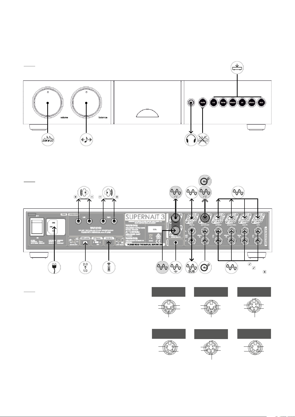
SUPERNAIT 3
5. Controls and Connections
5.1 Front Panel Controls
Note: Icon descriptions can be found in Section 16.
5.2 Rear Panel Connections
Note: Icon descriptions can be found in Section 16.
ch1
-ve
nc
nc
ch2
cd and tuner in
ch1
-ve
ch1
(out)
ch2
(out)
ch2
av and stream
in/out
+ve
-ve
+ve
ch1
ch2
aux 2 in
Note: The link plug should be removed only if a power
supply upgrade is to be used or an alternative preamplier
is to use the SUPERNAIT 3 power amplier section. It
should remain tted in all other circumstances.
ch2
ch2
ch1
ch1
nc
+ve
-ve
-ve
bi-amp out
power amp in
+ve
-ve
+ve
ch1
ch2
preamp out
DIN:
Phono:
DIN + Phono:
 Loading...