


E N G L I S H
D E U T S C H
F R A N Ç A I S
I TA L I A N O
O W N E R S M A N U A L
n-Vi Home Theatre System

SAFETY INSTRUCTIONS
In order to comply with current European safety regulations it is essential that the Naim loudspeaker connectors supplied with amplifiers and loudspeakers are used.
Do not under any circumstances allow anyone to modify your Naim equipment without first checking with the factory, your retailer, or your distributor. Unauthorised modifications will invalidate your guarantee.
Equipment must not be exposed to dripping or splashing and no objects filled with liquid, such as vases, should be placed on the equipment.
For your own safety do not under any circumstances open Naim equipment without first disconnecting it from the mains.
Warning: an apparatus with CLASS I construction shall be connected to a mains socket outlet with a protective earthing connection.
Where the mains plug or an appliance coupler is used as the disconnect device, the disconnect device shall remain
readily operable. To disconnect the equipment from the mains remove the mains plug from the mains outlet.
The following label is attached to all mains powered equipment:
WARNING
THIS APPARATUS
MUST BE EARTHED
NOTE
This equipment has been tested and found to comply with the relevant EMC and Safety Standards, and, where applicable, also complies with the limits for a class B digital device, pursuant to Part 15 of the FCC Rules.
These limits are designed to provide reasonable protection against harmful interference in a residential installation.
This equipment generates, uses and can radiate radio frequency and, if not installed and used in accordance with the instructions, may cause harmful interference to radio communications. However, there is no guarantee that interference will not occur in a particular installation. If this equipment does cause harmful interference to radio or television reception, which can be determined by turning off and on, the user is encouraged to try to correct the interference by one or more of the following measures:
•Reorient or relocate the receiving antenna.
•Increase the separation between the equipment and the receiver.
•Connect the equipment into an outlet on a circuit different from that to which the receiver is connected.
•Consult your Naim retailer or an experienced radio/TV technician for help.
Contents
Page |
Section |
|
E1 |
1 |
Connections |
|
2 |
Mains Power Connection |
E2 |
3 |
General Installation |
E3 |
4 |
Product Introduction and Contents |
E4 |
5 |
Connections |
E6 |
6 |
Control and Setup |
E9 |
7 |
On Screen Setup |
E14 |
8 |
Front Panel Setup |
E16 |
9 |
Operation |
E20 |
10 |
Video Formats Explained |
E21 |
11 |
DAB/FM Tuner |
E22 |
12 |
System Connections |
E23 |
13 |
Trouble-shooting |
E25 |
14 |
Specification |
E25 |
|
Licence Acknowledgements and Declaration of |
|
|
Conformity |

naim Introduction
Naim Audio products are conceived with performance as the top priority. Careful installation will help ensure that their full potential is achieved.
This manual covers the n-Vi all-in-one home theatre system. It begins with some general installation notes and statutory safety warnings. More product specific information begins in Section 4.
1 Connections
It is important for both safety and performance that the standard cables supplied are not modified.
1.1 Interconnect Cables
If options are available with your equipment and installation, DIN interconnect sockets should be used in preference to RCA Phono sockets. One end of each Naim interconnect cable is marked with a band to establish its correct orientation. The band denotes the end that connects to the signal source.
Interconnect plugs and sockets should be kept clean and free from corrosion. The easiest way to clean them is to switch off the equipment, pull the plugs out of their sockets, and push them back in again. Contact cleaners and “enhancers” should not be used as the film they deposit may degrade the sound.
1.2 Loudspeaker Cables
Although any high quality loudspeaker cable is suitable, we recommend that Naim loudspeaker cable is used. Naim loudspeaker cable is directional and should be oriented so that the printed arrow points towards the speakers. The loudspeaker connectors supplied are designed to comply with European safety legislation and must be used.
Contact your local retailer or distributor for further advice on loudspeaker cables and connectors.
2 Mains Power Connection
Where fused plugs are used 13 amp fuses should be fitted. Fuses of a lower rating will fail after
a period of use. Do not wire voltage dependent resistors or noise suppressors into mains plugs. They degrade the mains supply and the sound.
The wire which is coloured BLUE must be connected to the terminal in the plug which is marked with the letter N or coloured BLACK.
The wire which is coloured BROWN must be connected to the terminal in the plug which is marked with the letter L or coloured RED.
2.2 Equipment Fuses
Mains powered Naim Audio equipment is fitted with a mains input fuse on the rear panel adjacent to the mains input socket. Replace it if necessary only with the spare fuse supplied or with identical fuses. Repeated failure of this fuse points to an equipment or system fault that should be investigated by your retailer or at the factory by Naim itself.
2.3 Non-rewirable Mains Plugs
If a non-rewirable plug is cut from a mains lead (for whatever purpose) the plug MUST be disposed of in a way to render it totally useless. Considerable shock hazard exists if the cut-off plug is inserted into a mains outlet.
2.4 Mains Circuits and Cables
A hi-fi system usually shares a mains circuit with other household equipment some of which can cause distortion of the mains waveform. A separate mains circuit (ideally with a 30 or 45 Amp rating) may reduce such distortion and improve system performance. Advice on the installation of a separate mains circuit should be sought from a qualified electrician.
Do not substitute alternative mains leads and plugs to those supplied. They are selected to offer the best possible performance.
2.1 Mains Plug Wiring
In some territories a mains plug may need to be fitted to the supplied mains lead. As the colours of the wires in the mains lead may not correspond with the coloured markings identifying the terminals in the plug proceed as follows:
The wire which is coloured GREEN-AND-YELLOW must be connected to the terminal in the plug which is marked by the letter E or by the safety earth symbol or coloured GREEN or
GREEN and YELLOW.
E1

naim Introduction
3 General Installation
Naim equipment is designed to offer the finest performance possible avoiding compromise wherever practical. This can lead to circumstances that may be unfamiliar. The notes that follow contain advice specifically related to Naim equipment as well as more general warnings about the use of domestic audio products. Please read them carefully.
3.1 Siting The Equipment
Some Naim equipment is extremely heavy. Check the weight of the equipment prior to lifting and if necessary use more than one person so that it can be moved safely. Ensure that your equipment rack or table can easily support the weight and is stable.
3.2 Switching On
Always use the switch on the product rather than a mains outlet switch to switch the product on.
A “thump” may be heard from the loudspeakers as power amplifiers are switched on. This is normal, will not cause any loudspeaker damage and does not point to any fault or problem. A mild “pop” may also be heard shortly after equipment is switched off.
3.3 Running In
Naim equipment takes a considerable time to run in before it performs at its best. The duration varies, but under some conditions the sound may continue to improve for over a month. Better and more consistent performance will be
achieved if the system is left switched on for long periods. It is worth remembering however that equipment left connected to the mains can be damaged by lightning.
3.4 Radio Interference
In some circumstances, depending on where you live and the earthing arrangements in your home, you may experience radio frequency interference. Controls on broadcasting in some territories allow very high levels of radio frequency radiation and both the choice and exact siting of equipment may be critical. Susceptibility to radio frequency interference is related to the wide internal bandwidth necessary for high sound quality. A radio frequency filter kit is available for some Naim equipment but sound quality will be progressively compromised as more elements of the kit are fitted. In situations of extreme radio interference Naim equipment may be unsuitable.
3.5 Lightning Precautions
Your Naim hi-fi system can be damaged by lightning and should be turned off and disconnected from the mains when there is risk of lightning strike. For complete protection all mains plugs and any aerial cables should be disconnected when not in use.
3.6 Problems?
Consumer protection varies from country to country. In most territories a retailer must be prepared to take back any equipment he has sold if it cannot be made to work satisfactorily. A problem may be due to a fault in the system or its installation so it is essential to make full use of your
dealer’s diagnostic skills. Please contact your local distributor, or Naim Audio directly, if any difficulties cannot be resolved.
Some Naim equipment is made in special versions for different territories and this makes it impracticable to arrange international guarantees. Please establish the local guarantee arrangements with your retailer. Contact Naim Audio directly for help and advice if necessary.
3.7 Service and Updates
It is essential that repairs and updates are only carried out by an authorised Naim retailer or at the factory by Naim itself. Many components are custom made, tested or matched and appropriate replacements are often unobtainable from other sources.
Direct contact to Naim for service or update information should be made initially through Customer Services:
Tel: +44 (0)1722 426600
Email: info@naim-uk.com
Please quote the product serial number (found on its rear panel) in all correspondence.
E2

n-Vi Introduction
4 Product Introduction and Contents
This manual covers installation and operation of the n-Vi all-in-one home theatre system. With the n-Vi, combining DVD, home theatre and genuine high-end hi-fi music reproduction is simple. The n-Vi includes everything you need in one box: DVD and CD player, AV Processor, audio preamplifier, five channel audio power amplifier and an optional DAB*/FM tuner. Just add speakers and a display.
The n-Vi is fundamentally straightforward in use, however its versatility and comprehensive functionality mean that a little time spent reading will help ensure problem-free setup and use.
The n-Vi should be installed on a dedicated equipment stand intended for the purpose. Care should be taken to ensure that it is level. Do not switch on the n-Vi until all input and output connections are made. Make sure you are familiar with the safety warnings and general installation advice contained within the first part of this manual.
Following this introduction, the manual is divided into the following sections.
Contents
5.Connections
5.1Signal Inputs
5.2Control Inputs
5.3Video Outputs
5.4Audio Outputs
5.5Speaker Outputs
5.6Control Outputs
5.7Rear Panel and Connections
6.Control and Setup
6.1The User Interface
6.2The Narcom DV Handset
6.3Recommended Initial Setup
7.On Screen Setup
7.1DVD Playback Setup
7.2System Setup
7.3Video Setup
7.4Progressive Scan Setup
7.5Audio Setup
7.6Speaker Setup
7.7Parental Control Setup
7.8Exit On Screen Setup
8.Front Panel Setup
8.1Video System and Format Selection
8.2Speaker, Input and Audio Setup
8.3Miscellaneous Setup
8.4Clock Setup (requires DAB/FM Module)
8.5Alarm Setup (requires DAB/FM Module)
8.6Exit Front Panel Setup
9.1Input Selection and Volume Control
9.2Playback Control
9.3Playback Options
9.4Accessory Functions
9.5Decode Modes - Selection and Availability
9.6Channel Schemes and Speakers
9.7Surround Encoding Technology Explained
10.Video Formats Explained
10.1Interlaced and Progressive Scan Video
10.2Video Interface Formats
11.DAB*/FM Tuner
11.1DAB Menu and Operation
11.2FM Menu and Operation
12.System Connections
12.1n-Vi with NAC 252, Supercap and NAP 250
13.Trouble-shooting
13.1Video and Disc Playback
13.2Audio
14.Specification
* DAB radio broadcasts are not available in all territories.
E3

n-Vi Connections
5 Connections
Once the n-Vi is positioned on a rack or furniture unit it can be connected to a mains supply. Use the mains cable supplied. Do not switch on the n-Vi until all audio, video and control connections have been made.
The appropriate input and output connections will depend on the type of system the n-Vi is to be used in. An Illustration of the n-Vi input and output connections can be found on the page opposite while a diagram illustrating the n-Vi integrated with an existing stereo system can be found in Section 12.
It is important that high quality cable is used for signal and speaker connections. Your local retailer or distributor will be able to offer advice.
5.1 Signal Inputs
The n-Vi can accept three digital and four analogue audio inputs for the connection of external source equipment. Two of the digital inputs are connected via RCA-phono sockets and one via an optical connector. Two of the analogue inputs are connected via RCA-phono socket pairs and one via a 5-pin DIN socket. One RCA-phono analogue input socket pair (Input A3) is duplicated on the n-Vi front panel with a stereo 3.5mm jack socket. This socket is intended for the temporary connection of portable music players. Insertion of a plug into the front panel
jack socket will automatically switch the n-Vi to this input. If any equipment is simultaneously connected to the rear panel A3 input sockets its audio signal will be mixed with the front panel signal. Removal of the front panel input plug will automatically switch the n-Vi to the previously selected input.
Table 5.3
If the n-Vi has a DAB/FM Radio Upgrade fitted it will also have an F-Type radio aerial input socket on the rear panel. Indoor aerials can be used although best results are likely to be obtained from roof aerials mounted as high as posssible. Use high quality 75Ω aerial cable for connecting aerials.
Use of an aerial preamplifier may disturb the FM muting operation of the tuner and may cause other problems. Such preamplifiers should therefore only be used as a last resort. An aerial combining unit may be used to combine signals from separate DAB and FM aerials. Your local retailer or distributor will be able to offer specific advice on local DAB and FM signal reception.
For details of all signal input sockets see Diagram 5.7.
5.2 Control Inputs
The n-Vi provides control inputs that enable it to be integrated with remote handset (RC5) signal repeaters and optionally with multi-room equipment control systems. The RC5 signal is connected through a single RCA-phono socket and the optional multi-room control input connected through an RJ45 socket. For details of all control input sockets see Diagram 5.7.
5.3 Video Outputs
The n-Vi can provide video outputs in a number of different formats on a variety of connection sockets. Each format and socket is appropriate for alternative display types - TV, CRT Monitor, TFT Monitor, Plasma, Projector, etc. - and it is important for the best picture quality that the appropriate socket is used. Table 5.3 lists, in order of preference, connection formats for any display device. Select, from the connection options available on your display, the one nearest
the top of the list. For details of all video output sockets see Diagram 5.7.
Preferred Video Connections
Rank |
Connection |
|
|
Order |
Connection |
Cable/Socket |
Notes |
|
|||
|
Format |
Type |
|
First |
DVi |
DVi |
Digital Progressive Scan |
Second |
RGB |
3 x BNC |
Analogue Progressive Scan |
Third |
YPbPr |
3 x BNC |
Analogue Progressive Scan |
Fourth |
RGB |
SCART |
Analogue Interlaced |
Fifth |
YPbPr |
SCART |
Analogue Interlaced |
Sixth |
S-Video |
4-pin mini DIN Analogue Interlaced |
|
Seventh |
Composite |
SCART |
Analogue Interlaced |
Note: Section 10 carries an explanation of the video formats listed.
Note: RGB progressive scan output is disabled when replaying
Macrovision encoded material.
5.4 Audio Outputs
The n-Vi provides one stereo analogue audio output via a 5-pin DIN socket and one digital audio output via a single RCA-phono socket.
These sockets enable the n-Vi to be connected to an external audio preamplifier or alternative multi-channel decoder respectively. In the case of multi-channel programme material, the signal present on the analogue output is the front left and right channels. Analogue programme material input to the n-Vi from an external source is not available from the digital output. The n-Vi also provides one analogue subwoofer output via a single RCA-phono socket. For details of all audio signal output sockets see Diagram 5.7.
E4

n-Vi Connections
5.5 Speaker Outputs
The n-Vi provides five speaker output sockets each rated at 90 watts into 4Ω. The five speaker outputs are intended to be connected to the front left, front right, centre, surround left and surround right speakers. In order to comply with European safety legislation speakers should be connected using the supplied Naim Audio n-Vi speaker plugs only. Naim Audio speaker cable is recommended although alternatives are possible. Your local retailer or distributor will be able to offer advice.
When connecting speakers ensure that each positive pin - identified by a “ ” mark on the side of the connector body - is always inserted to the positive output sockets. Also ensure that the connections at the speaker are connected with the same polarity. For details of the speaker output sockets see Diagram 5.7.
5.6 Control Outputs
The n-Vi provides control outputs that enable it to be integrated with remote handset signal (RC5) repeaters and optionally with multi-room equipment control systems. The RC5 output is
connected via a single RCA-phono socket and the optional multiroom control output is connected via an RJ45 socket. For more detail on connection to the control input sockets see Diagram 5.7.
5.7 Rear Panel and Connections
RGB and YPbPr Video outputs. Use only if higher quality alternatives not supported by display. See Table 5.3
Optional multi-room comms input and output
|
Optional DAB and FM Radio aerial input |
RC5 input and output |
|||||||||||||
Analogue audio output. Front left and right |
|
DVI Video output. |
|||||||||||||
|
Analogue audio input one |
|
Use for highest |
||||||||||||
|
quality if supported |
||||||||||||||
Digital audio optical input |
|||||||||||||||
|
|
by display |
|||||||||||||
|
|
|
|
|
|
|
|
|
|
|
|
|
|
|
|
|
|
|
|
|
|
|
|
|
|
|
|
|
|
|
|
|
|
|
|
|
|
|
|
|
|
|
|
|
|
|
|
|
|
|
|
|
|
|
|
|
|
|
|
|
|
|
|
|
|
|
|
|
|
|
|
|
|
|
|
|
|
|
|
|
|
|
|
|
|
|
|
|
|
|
|
|
|
|
|
|
|
|
|
|
|
|
|
|
|
|
|
|
|
|
|
Power |
Mains input |
SCART Video |
Digital |
Analogue |
Subwoofer |
Left front, right |
switch |
and fuse |
output. Use only |
audio |
audio |
output |
front, centre, left |
|
S-Video output. Use |
f higher quality |
coaxial |
nputs two |
Digital |
surround and |
|
alternatives not |
nputs |
and three |
right surround |
||
|
only if higher quality |
audio |
||||
|
supported by |
two and |
|
speaker outputs |
||
|
alternatives not |
|
coaxial |
|||
|
display. See |
three |
|
|
||
supported by display. |
|
output |
|
|||
Table 5.3 |
|
|
|
|||
|
See Table 5.3 |
|
|
|
|
|
|
|
|
|
|
|
|
|
|
|
|
|
DIN Audio Input |
DIN Audio Output |
|
|
|
|
|
ch1 |
ch1 |
|
|
|
|
|
(left) |
(left) |
|
|
|
|
|
ch2 |
ch2 |
|
|
|
|
|
(right) |
(right) |
|
|
|
|
|
negative |
negative |
E5
n-Vi Control and Setup
6 Control and Setup
6.1.1 On Screen Setup
Once all the input and output connections are made the n-Vi can be set up. Although the n-Vi can be set up and controlled from its front panel, many
parameters are best set from the listening position, so use of the NARCOM DV handset is recommended.
When initially switched on from the rear panel, the n-Vi will, after a short delay, enter standby mode. Standby is indicated by an illuminated front panel standby button. To wake the n-Vi press the handset standby key or front panel standby button. The n-Vi will wake in either the factory default state, if it is previously unused, or in the state in which it was last shut down. Once the n-Vi is switched on, the video display and any other associated equipment should also be switched on.
Note: The n-Vi can be returned to its factory default settings by pressing and holding the handset clear key with no disc loaded.
6.1 The User Interface
The n-Vi can generally be operated from its front panel or from the Narcom DV remote handset in either AV or DVD modes. The On Screen Display and Front Panel Display provide operational feedback.
Note: If nothing is displayed when the n-Vi and display are first switched on some Front Panel Setup video output options may need to be changed. See Section 8.1.
The n-Vi has two setup routines. On Screen Setup (Section 7) and Front Panel Setup (Section 8). On Screen Setup configures parameters that apply to system-wide setup, DVD playback and video display.
Note: Some On Screen Setup parameters can also be accessed and adjusted via Front Panel Setup.
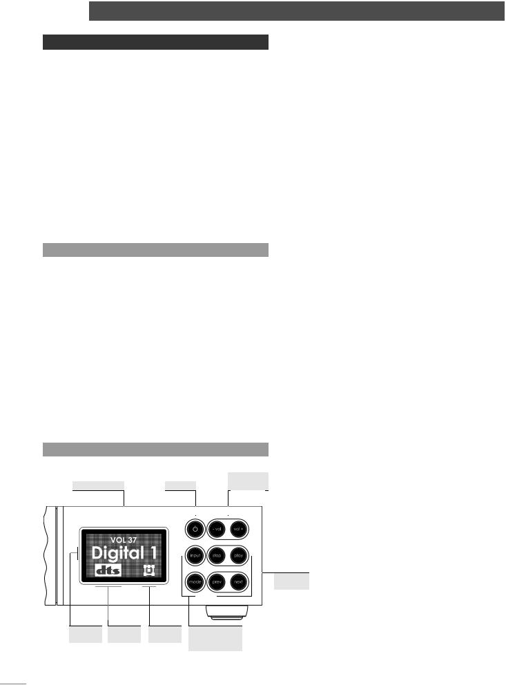
Diagram 6.1.2
Front panel controls and display.
Output volume |
Standby |
|
Volume |
||||||||
|
adjustment |
||||||||||
|
|
|
|
|
|
|
|
|
|
|
|
|
|
|
|
|
|
|
|
|
|
|
|
|
|
|
|
|
|
|
|
|
|
|
|
|
|
|
|
|
|
|
|
|
|
|
|
Selected |
Decode |
Channel |
Signal input |
nput |
mode |
scheme |
and decode |
|
|
|
mode selection |
During On Screen Setup, all functions are accessed via a
cascading menu system with the handset |
(up), |
(down), |
|
(left), |
(right) and ok keys. To navigate through the top |
||
level and second level menus use the handset up ( |
) and |
||
down ( ) keys. To confirm a selection press the ok key. To return to the previous menu without making a selection or a change use the rtn (return) key, or press setup to exit from the setup menus.
To navigate through the third level menu use the handset left
() and right ( ) keys. To increase or decrease a parameter
value use the up ( ) and down ( ) keys respectively. Use the ok key to confirm the setting. To return to the previous menu without making a selection or a change use the rtn (return) key. Press setup to exit from the setup menus.
Note: The handset clear key can be used at any time to clear any On Screen Display.
6.1.2 Front Panel Setup, Controls and Display
During Front Panel Setup, functions are accessed via a cascading menu system with front panel -vol, rev, input, play and stop buttons providing menu navigation and ok commands. These buttons are illuminated in setup mode. In normal mode the buttons revert to operating as described below and illustrated in the diagram.
Note: The handset navigation keys can also be used for Front Panel setup.
standby: Switches the n-Vi in and out of standby mode. -vol: Decreases volume
vol+: Increases volume input: Selects next signal input
mode: Selects next AV decode mode
stop: Stops playback. Press while stopped opens drawer. play: Starts playback. Press while in play pauses play.
Press while drawer open closes drawer. rev Selects previous chapter or track. next: Selects next chapter or track.
The n-Vi front panel display provides feedback of volume level, input selection, decode mode, channel scheme and, if the optional DAB/FM tuner is fitted, radio station identity and data. The front panel display will switch off after two minutes of inactivity.
Player transport
E6
n-Vi Control and Setup
6.1.3 Front Panel Channel Scheme Icon
The term “channel scheme” describes the array of speakers in use. The channel scheme operating at any time is linked to the input signal, speaker setup and decode mode and is illustrated on the n-Vi front panel display by an icon in the bottom right hand corner (See Diagram 6.1.3). The icon changes as different input signals and decode modes are selected (either manually or automatically) or speaker setups are specified.
The icon represents a listening room with front left, centre, front right, surround left, surround right and subwoofer speakers. Each speaker element within the icon shows or hides to denote presence in the speaker setup, grows or shrinks to reflect “large” or “small” specification (see Paragraph 7.6.1), or is filled or empty to denote its presence or absence in the channel scheme.
Diagram 6.1.3
Front panel display channel scheme icon
Left |
Centre |
Right |
Left |
Right |
Subwoofer
Left |
Right |
Surround |
Surround |
Example of a channel scheme icon illustrating a 5.1 system with large front, centre and surround
speakers and a subwoofer.
Subwoofer
Left |
Right |
Surround |
Surround |
Example of a channel scheme icon illustrating a 4.1 system with large front speakers, a subwoofer and inactive small surround speakers.
Note: As a stereo signal has no native subwoofer content Bass Mix has been enabled to generate subwoofer information.
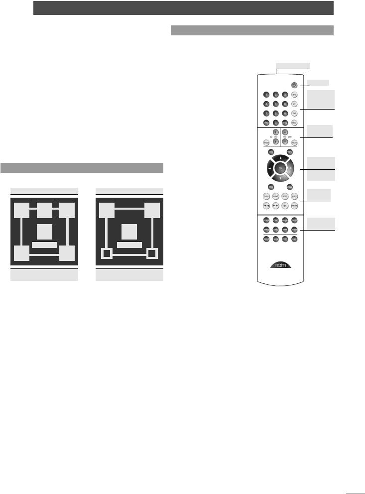
6.2 The NARCOM DV Handset
The NARCOM DV is a dedicated remote handset for the n-Vi, DVD5 and AV2. It will also operate the core functions of a Naim
CD player, preamplifier or |
|
|
|
|
integrated amplifier. |
|
Numeric keys |
||
The System Component |
|
|
|
Standby |
|
|
|
||
keys switch the handset |
|
|
|
|
|
|
|
|
|
mode of operation as |
|
|
|
System |
|
|
|
||
appropriate to different |
|
|
|
component |
|
|
|
keys |
|
components (preamplifier, |
|
|
|
|
|
|
|
|
|
CD, AV, DVD, n-Vi). |
|
|
|
|
re Switches the action of |
|
|
|
Volume |
|
|
|
and mute |
|
appropriate keys to operate |
|
|
|
|
|
|
|
|
|
a preamplifier or integrated |
|
|
|
|
|
|
|
|
|
amplifier. |
|
|
|
OSD menu |
|
|
|
|
|
cd: Switches the action of |
|
|
|
nterface |
appropriate keys to operate |
|
|
|
n-Vi |
|
|
|
Functions |
|
a CD player. |
|
|
|
|
|
|
|
|
|
av Switches the action |
|
|
|
Player |
|
|
|
transport |
|
of appropriate keys to |
|
|
|
|
|
|
|
|
|
operate an AV2 audio-visual |
|
|
|
|
|
|
|
|
|
processor or n-Vi system |
|
|
|
n-Vi |
|
|
|
||
(including DAB/FM module). |
|
|
|
Functions |
dvd: Switches the action of |
|
|
|
|
|
|
|
|
|
appropriate keys to operate |
|
|
|
|
a DVD player or n-Vi system |
|
|
|
|
(including DAB/FM module). |
|
|
|
|
Note: An audio CD played |
|
|
|
|
in a DVD/n-Vi player would |
|
|
|
|
still be controlled with the |
|
|
|
|
handset in DVD mode. |
|
|
|
|
Depending on the System Component setting and, in some cases signal input selected, the Numeric keys select disc titles, groups, tracks or chapters or tuner presets.
Note: To select DVD titles or DVD-A groups place a leading zero before the required title or group number.
The twin sets of Volume and Mute keys remain available to either an AV processor (or n-Vi) or preamplifier regardless of the setting of the System Component keys.
The Player Transport keys will switch between CD and DVD player operation depending on the System Component key selection. If preamplifier or AV is selected the Player Transport keys will operate the last component type selected.
E7
 Loading...