

Page 1
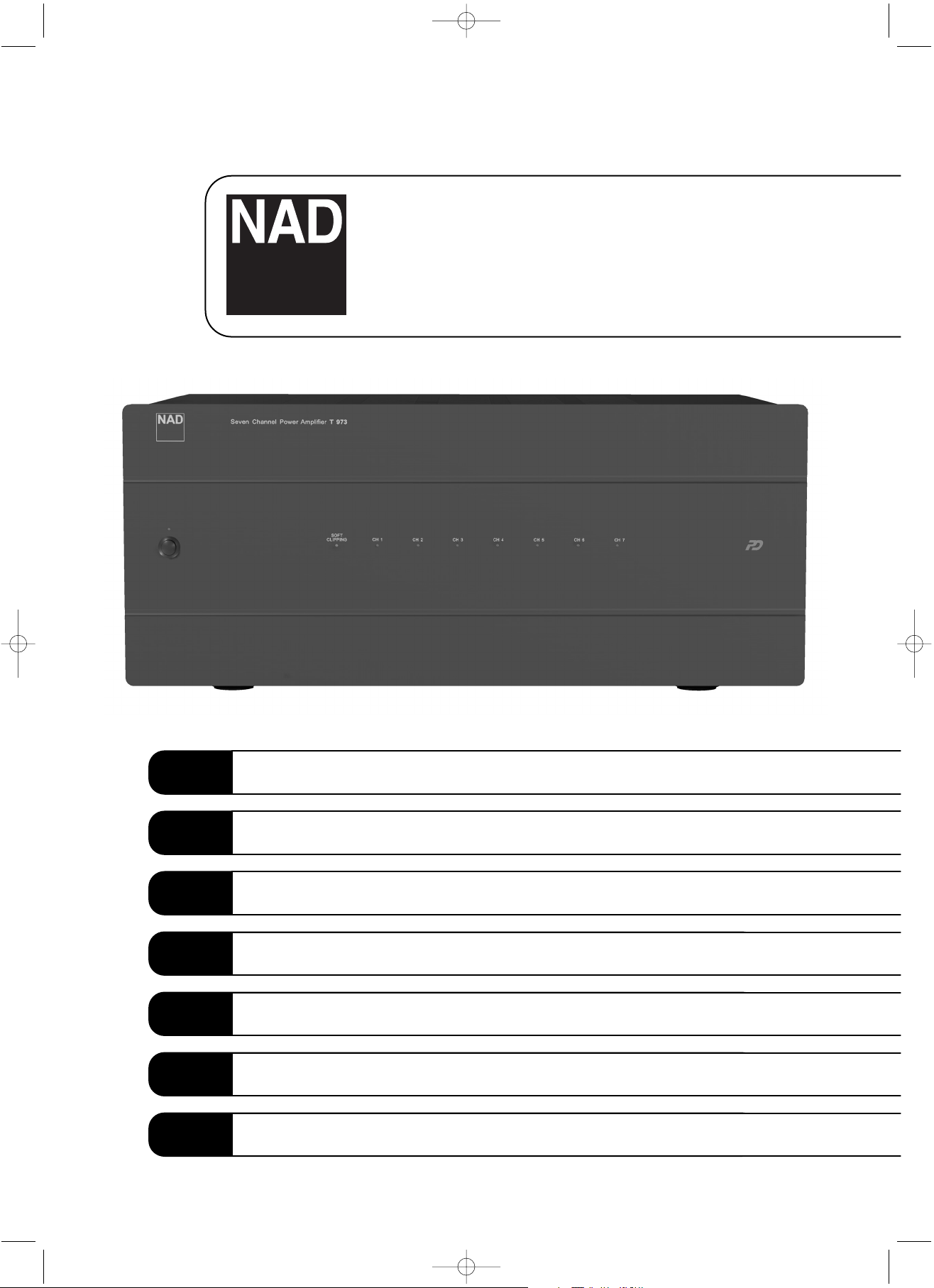
T 973
Seven Channel Power Amplifier
Owner’s Manual
GB
Manuel d’Installation
F
Bedienungsanleitung
D
Manual del Usario
E
Manuale delle Istruzioni
I
Manual do Proprietário
P
Bruksanvisning
S
T 973manual C.qxd 8/21/2006 11:39 AM Page 1
Page 2
Warning: To reduce the risk of fire or electric shock, do not
expose this unit to rain or moisture.
The lightning flash with an arrowhead symbol within an equilateral
triangle, is intended to alert the user to the presence of uninsulated
“dangerous voltage” within the product’s enclosure that may be of
sufficient magnitude to constitute a risk of electric shock to persons.
The exclamation point within an equilateral triangle is intended to
alert the user to the presence of important operating and
maintenance (servicing) instructions in the literature accompanying
the product.
Do not place this unit on an unstable cart, stand or tripod, bracket
or table. The unit may fall, causing serious injury to a child or adult
and serious damage to the unit. Use only with a cart, stand, tripod,
bracket or table recommended by the manufacturer or sold with
the unit. Any mounting of the device on a wall or ceiling should
follow the manufacturer’s instructions and should use a mounting
accessory recommended by the manufacturer.
An appliance and cart combination should be moved with care.
Quick stops, excessive force and uneven surfaces may cause the
appliance and cart combination to overturn.
Read and follow all the safety and operating instructions before
connecting or using this unit. Retain this notice and the owner’s
manual for future reference.
All warnings on the unit and in its operating instructions should be
adhered to.
Do not use this unit near water; for example, near a bath tub,
washbowl, kitchen sink, laundry tub, in a wet basement or near a
swimming pool.
The unit should be installed so that its location or position does not
interfere with its proper ventilation. For example, it should not be
situated on a bed, sofa, rug or similar surface that may block the
ventilation openings; or placed in a built-in installation, such as a
bookcase or cabinet, that may impede the flow of air through its
ventilation openings.
The unit should be situated from heat sources such as radiators,
heat registers, stoves or other devices (including amplifiers) that
produce heat.
The unit should be connected to a power supply outlet only of the
voltage and frequency marked on its rear panel.
The power supply cord should be routed so that it is not likely to be
walked on or pinched, especially near the plug, convenience
receptacles, or where the cord exits from the unit.
Unplug the unit from the wall outlet before cleaning. Never use
benzine, thinner or other solvents for cleaning. Use only a soft
damp cloth.
The power supply cord of the unit should be unplugged from the
wall outlet when it is to be unused for a long period of time.
Care should be taken so that objects do not fall, and liquids are not
spilled into the enclosure through any openings.
This unit should be serviced by qualified service personnel when:
A. The power cord or the plug has been damaged; or
B. Objects have fallen, or liquid has been spilled into the unit; or
C. The unit has been exposed to rain or liquids of any kind; or
D. The unit does not appear to operate normally or exhibits a
marked change in performance; or
E. The device has been dropped or the enclosure damaged.
DO NOT ATTEMPT SERVICING OF THIS UNIT
YOURSELF. REFER SERVICING TO QUALIFIED
SERVICE PERSONNEL
Upon completion of any servicing or repairs, request the service
shop’s assurance that only Factory Authorized Replacement Parts
with the same characteristics as the original parts have been used,
and that the routine safety checks have been performed to
guarantee that the equipment is in safe operating condition.
REPLACEMENT WITH UNAUTHORIZED PARTS MAY RESULT IN FIRE,
ELECTRIC SHOCK OR OTHER HAZARDS.
ATTENTION
POUR ÉVITER LES CHOC ELECTRIQUES, INTRODUIRE LA
LAME LA PLUS LARGE DE LA FICHE DANS LA BORNE
CORRESPONDANTE DE LA PRISE ET POUSSER JUSQU’AU
FOND.
CAUTION
TO PREVENT ELECTRIC SHOCK, MATCH WIDE BLADE OF
PLUG TO WIDE SLOT FULLY INSERT.
If an indoor antenna is used (either built into the set or installed
separately), never allow any part of the antenna to touch the metal
parts of other electrical appliances such as a lamp, TV set etc.
CAUTION
POWER LINES
Any outdoor antenna must be located away from all power lines.
OUTDOOR ANTENNA GROUNDING
If an outside antenna is connected to your tuner or tunerpreamplifier, be sure the antenna system is grounded so as to
provide some protection against voltage surges and built-up static
charges. Article 810 of the National Electrical Code, ANSI/NFPA No.
70-1984, provides information with respect to proper grounding of
the mast and supporting structure, grounding of the lead-in wire to
an antenna discharge unit, size of grounding conductors, location of
antenna discharge unit, connection to grounding electrodes and
requirements for the grounding electrode.
a. Use No. 10 AWG (5.3mm2) copper, No. 8 AWG (8.4mm2)
aluminium, No. 17 AWG (1.0mm2) copper-clad steel or bronze
wire, or larger, as a ground wire.
b. Secure antenna lead-in and ground wires to house with stand-off
insulators spaced from 4-6 feet (1.22 - 1.83 m) apart.
c. Mount antenna discharge unit as close as possible to where lead-
in enters house.
d. Use jumper wire not smaller than No.6 AWG (13.3mm2) copper,
or the equivalent, when a separate antenna-grounding electrode
is used. see NEC Section 810-21 (j).
EXAMPLE OF ANTENNA GROUNDING AS PER NATIONAL ELECTRICAL
CODE INSTRUCTIONS CONTAINED IN ARTICLE 810 - RADIO AND
TELEVISION EQUIPMENT.
NOTE TO CATV SYSTEM INSTALLER: This reminder is
provided to call the CATV system installer’s attention to
Article 820-40 of the National Electrical Code that provides
guidelines for proper grounding and, in particular, specifies
that the ground cable ground shall be connected to the
grounding system of the building, as close to the point of
cable entry as practical.
NOTES ON ENVIRONMENTAL PROTECTION
At the end of its useful life, this product must not be disposed
of with regular household waste but must be returned to a
collection point for the recycling of electrical and electronic
equipment. The symbol on the product, user's manual and
packaging, point this out.
The materials can be reused in accordance with their markings.
Through re-use, recycling of raw materials, or other
forms of recycling of old products, you are making an
important contribution to the protection of our
environment.
Your local administrative office can advise you of the
responsible waste disposal point.
CAUTION
RISK OF ELECTRIC
SHOCK DO NOT OPEN
A TTENTION:
RISQUE DE CHOC ELECTRIQUE
NE PAS OUVRIR
CAUTION: TO REDUCE THE RISK OF ELECTRIC
SHOCK, DO NOT REMOVE COVER (OR BACK). NO
USER SERVICEABLE PARTS INSIDE. REFER SERVICING
TO QUALIFIED SERVICE PERSONNEL.
IMPORTANT SAFETY INSTRUCTIONS
2
T 973manual C.qxd 8/21/2006 11:39 AM Page 2
Page 3
3
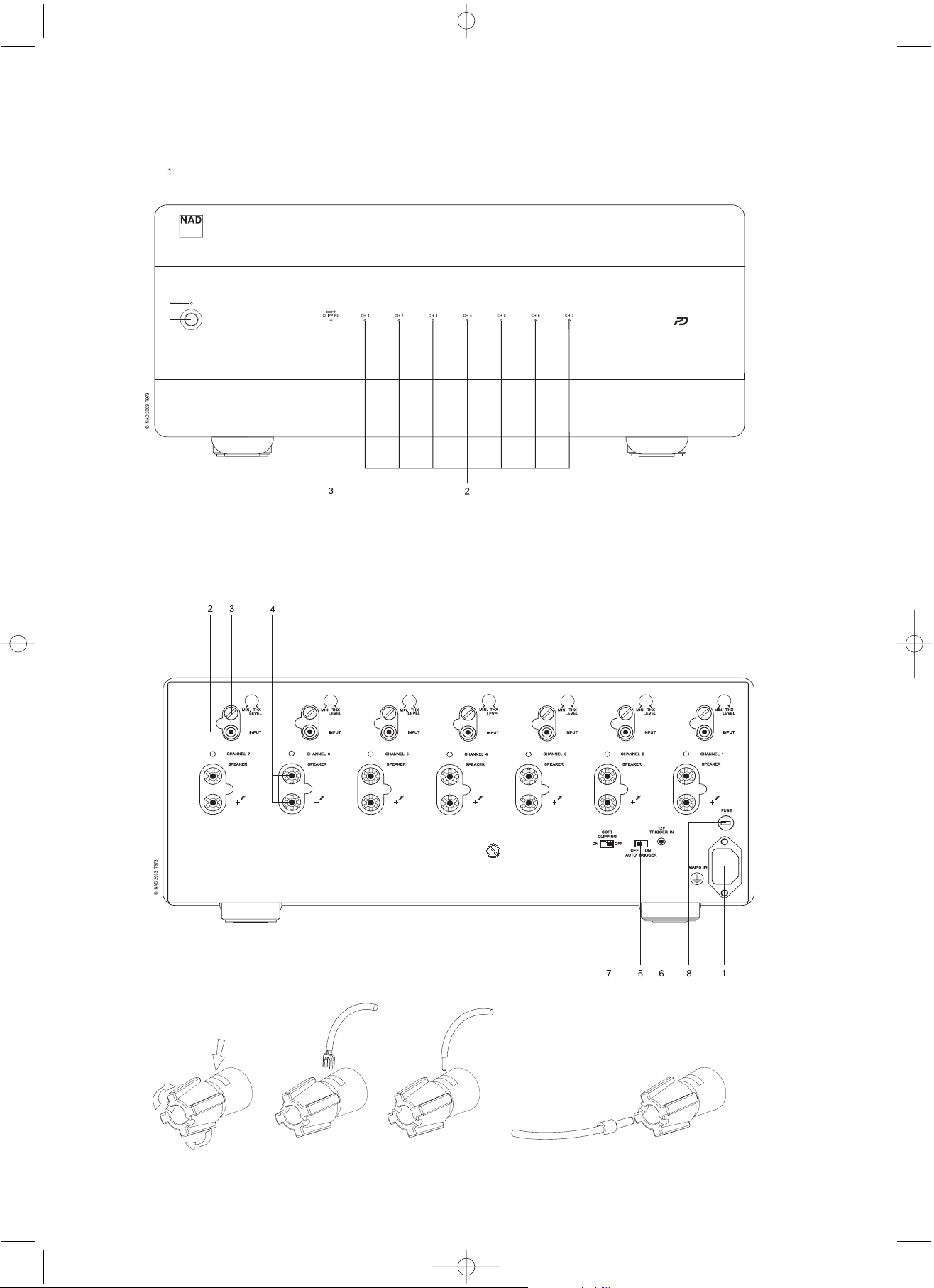
FRONT PANEL CONTROLS
REAR PANEL CONNECTIONS
FIGURE 1
T 973manual C.qxd 8/21/2006 11:39 AM Page 3
Seven Channel Power Amplifier T 973
GROUND
9
Spade
Wire
Pin
Page 4

GB
4
NAD T 973 Seven Channel Power Amplifier
ABOUT THE T 973
Designed specifically for home theater and custom installation setups, the NAD T 973 Power Amplifier delivers uncompromising
performance. It combines supreme reliability, flexibility, and
performance with outstanding value. Flexibility has always been an
important part of NAD components. Such flexibility is particularly
important in home theater and other multi-channel systems. That’s
because it is common for a multi-channel system to incorporate
different brands and models of loudspeakers. Often these speakers
have different levels of efficiency. The individual input level controls
for the seven channels of the NAD T 973 make it easy to
compensate for such differences in efficiency, and achieve the ideal
system balance. Ample dynamic headroom of the T 973 ensures that
the very wide dynamic range of modern cinema soundtracks and
digital music sources will be preserved. In addition, the T 973 will
handle low impedance speakers with ease.
The T 973 incorporates NAD’s unique Soft-Clipping circuitry in all
seven channels. Any amplifier can be overdriven if it is played too
loud, exceeding the maximum output power. Under such
circumstances, amplifiers produce extreme high levels of distortion
which, besides sounding very unpleasant, can damage your
loudspeakers. The Soft Clipping circuit suppresses such distortion and
minimizes the risk of damage to speakers. This is particularly
important with movie soundtracks which often contain very dynamic
outbursts in which, unlike music, it is difficult to hear this potentially
damaging distortion. The Soft Clipping LED on the front panel
illuminates when the Soft Clipping circuit is engaged. Soft Clipping
can be defeated with a rear panel switch.
The 12V trigger connection on the back panel allows the amplifier to
be switched from On to Stand-by and vice-versa remotely. This way,
the T 973 can be part of a system which can be turned on and off
with a single command, easing operation. The 12V trigger also
allows the amplifier to be installed in places not in easy reach.
THE DESIGN
The NAD T 973 houses seven individual amplifiers, each on separate
circuit board. Each amplifier channel acts as a “mono block” within
the chassis. Each input connector, and set of loudspeaker output
terminals, is directly connected to that channel’s circuit board. This
design eliminates extra wiring and keeps signal paths short.
Furthermore, this modular design increases reliability and thermal
efficiency. The input circuit uses a totally new dual differential input
topology that operates in true Class-A mode. The special
Holmgren™ toroidal transformer has less hum and magnetic leakage
than conventional toroidal transformers, but retains the usual
benefits of high efficiency and high power-to-weight ratio.
Ruggedness and reliability are critical in custom-installed systems. The
T 973 uses a combination of fuses and non-intrusive electronic
protection. This provides highly effective protection that does not
effect audio performance. Each channel is protected against excess
temperature, DC fault and loudspeaker short-circuit. The T 973’s
inherently conservative, high-voltage/high-current output stage has
been designed for years of trouble-free service.
POWERDRIVE
To meet the diverse requirements of high current drive and high
dynamic power, our patented PowerDrive amplifier circuit will build
further on our reputation for amazingly effective power. By adding a
second high-voltage rail to our well regulated high-current power
supply, we get an "overdrive" that can nearly double the continuous
power on a short term dynamic power basis. This is a further
development and refinement of our renowned Power Envelope
circuit, utilized by NAD in the 80's and 90's. PowerDrive differs from
Power Envelope in that it offers greater amplifier stability and low
impedance drive capability, resulting in less distortion when driving
real speakers with real program material
INSTALLATION PRECAUTIONS
WARNING - To reduce the risk of fire or electrical shock, do not
expose the amplifier to rain or moisture.
CAUTION - For units factory-set at 115 volts AC match the wide
blade of the power plug to the wide slot of the power outlet, to
prevent electrical shock. Be sure the plug is completely inserted into
the receptacle.
Turn off all the components in the system whenever connecting or
disconnecting any audio signal wiring. Once all signal connections
have been completed, turn down all the system’s main volume control
before turning the system components on. Then increase the volume
control setting carefully to avoid damage to the system components.
NOTES ON INSTALLATION LOCATION
Read and follow all the safety instructions on the first page of this
manual. To prevent a fire or shock hazard, do not place the amplifier
where it will be exposed to any water or moisture. If liquid
accidentally gets into the amplifier, immediately unplug the AC
power cord. Do not operate the amplifier again until it has been
examined by a service technician.
The amplifier generates a moderate amount of heat, requiring
ventilation. Do not obstruct the air outlet grilles on the top or
bottom covers. There should be at least 3 inches (7.5 cm) of
clearance above the amplifier and 1 inch (2.5 cm) to the sides. Do
not place the amplifier in an enclosed area, such as in a bookcase or
in a cabinet, unless it is very well ventilated. Be sure there is
adequate room behind the amplifier for signal input and speaker
output connections. If you want to locate the amplifier on a carpeted
floor, place a board under it in order to prevent it from sinking into
the carpet, blocking the air inlets on the bottom. Do not place the
amplifier where it will be exposed to direct sun light for prolonged
periods of time.
This unit may be installed on any sturdy, level surface.
NOTE: The amplifier’s weight must always rest on its bottom feet.
Never put the amp down on its rear panel, with its front panel facing
up. Doing so risks damage to the input/output connectors.
The power transformer in the T 973 generates a magnetic hum field
of moderate strength. Turntables (especially those with a moving-coil
pickup cartridge) should not be located near the amplifier. Magnetic
media, such as audio or video tapes and computer diskettes, should
not be stored near the amplifier.
T 973manual C.qxd 8/21/2006 11:39 AM Page 4
Page 5
REAR PANEL CONNECTIONS/CONTROLS
1. AC LINE CORD
Plug the AC line cord into a nearby wall outlet that provides the
correct AC power line voltage, as indicated on the back panel of the
unit. Do not plug the amplifier into a convenience outlet on your
preamp. The amplifier requires more power than these outlets
typically can provide.
2. INPUTS
Each of the seven independent power amplifiers within the T 973
has its own signal input connector. Before making any connections
to the amplifier, make sure the POWER is switched OFF.
Connect the signal cables from the preamplifier, surround sound
decoder, or other signal source to these inputs. For optimum heat
dissipation in an AV surround system, we recommend you allocate
the audio channels to the inputs as follows:
Input 1 = Right Main speaker
Input 2 = Right surround speaker
Input 3 = Center speaker
Input 4 = Left Surround speaker
Input 5 = Left Main speaker
Input 6 = Left Surround Rear speaker
Input 7 = Right Surround Rear speaker
3. INPUT LEVEL CONTROLS
The amplifier is equipped with separate input level controls for each
channel. Before turning on the T 973 for the first time, make sure all
level controls are in their normal full-clockwise position.
Under some circumstances, other settings may be useful for:
• Level-matching - In systems that incorporate speakers of varying
efficiencies, it may be necessary to reduce the settings of some
controls to achieve proper channel-to-channel balance.
• Extended volume-control range - Many stereo systems have so
much voltage gain that the speakers (or your ears) are over-driven
at any volume-control setting higher than 11 or 12 o’clock
position of the volume control. As a result you can use only the
lower half of the volume control’s range, where adjustments are
imprecise and channel-balance errors tend to be greater. If all
input level controls are reduced, you can turn up your
preamplifier’s volume control, making effective use of most of its
range. (Suggestion: Adjust the input level controls so that your
preferred maximum sound levels occur at about 2 or 3 o’clock on
the volume control.) As an added benefit, this procedure
suppresses any noise produced by the preamp’s high-level circuitry
(e.g. any residual hum or hiss that does not go away when the
Volume is turned down).
4. SPEAKER CONNECTIONS
This amplifier is equipped with special high-current binding-post
speaker terminals. Connect the loudspeakers with heavy-duty (16gauge or thicker) braided wire. Connections may be made in any of
three ways. [See Figure 1.]
• Strip off a half-inch (1 cm) of insulation from each speaker wire.
In each conductor, twist the thin strands of wire together.
Unscrew the knob, insert the bare wire into the opening at the
base of the binding post, and tighten the knob until it grasps the
wire securely. Check to be sure that there are no loose strands of
wire touching the chassis or an adjacent terminal.
• Spade lugs. Unscrew the knob, insert the U-shaped spade lug
behind the bushing, and tighten the knob until the spade lug is
secured.
• Install banana plugs on your speaker wires, and plug them into
the end of each binding post. The terminals are separated by 3/4
inch (l9mm), so they will accept dual-banana plugs (this option is
not available on units with 230V line voltage factory setting).
NOTE: Speakers must operate in phase with each other in order to
produce a proper stereo image and to reinforce rather than cancel
each other’s output at low frequencies. When connecting speakers,
take care that the red (positive) terminal on each loudspeaker is
connected to the corresponding terminal marked red (positive) on
the amplifier.
5. AUTO TRIGGER ON/OFF
Set the Auto Trigger switch to the On position to activate the 12Vtrigger. By connecting the 12V-trigger, the T 973 can be remotely
switched to On and Stand-by and vice-versa. When set to the Off
position, the 12V-trigger input is not active.
NOTE: With the Auto Trigger switch set to the ON position and the
12V-trigger input connected, the T 973 will switch from Off to
Stand-by when the Power Switch on the front panel is pressed. For
normal operation, ensure the switch is in the OFF position or that the
12V-trigger input socket is not connected.
6. 12V-TRIGGER INPUT
For external Power on/Stand-by switching, connect the 12V-trigger
output of a source component to this DC input jack. The center pin
is the live or + connection, the outer sleeve of the input jack is the
12V-trigger - or ground connection.
NOTES: The T 973’s 12V-trigger will work within a range of 6 to 15
V DC level and typically draws less than 10mA of current. Check the
specifications of the 12V-trigger source to ensure it is compatible
with the T 973’s 12V-trigger input. Do not exceed the recommended
voltage as this may cause damage to the T 973.
7. SOFT CLIPPING
When an amplifier is driven beyond its specified power output it
normally produces “hard clipping” or distortion of the signal. Such
hard clipping, in addition to sounding unpleasant, can damage the
speakers in the system. The NAD Soft Clipping circuit gently limits
the output waveform, minimizing audible distortion and reducing the
change of speaker damage when the amplifier is overdriven. We
recommend that the Soft Clipping switch on the back panel of the T
973 be left in the ON position when system is being operated at
levels that might exceed the amplifier’s power capacity. The LED on
the front panel indicates if Soft Clipping has been engaged.
8. FUSE HOLDER
There is a fuse holder nearby or next to the AC-line cord. In the
unlikely event a fuse may need to be replaced, unplug the line cord
form the wall. Then remove all connections from the amplifier. Only
replace the fuse with the same type, size, and specification.
GB
5
T 973manual C.qxd 8/21/2006 11:39 AM Page 5
Page 6
GB
6
9. GROUND CONNECTOR
The T 973 is provided with a GROUND terminal on the rear panel.
This terminal is connected directly to the chassis of the T 973. In
the event of radio hum or radio interference, this terminal can be
connected to a ‘true earth’ such as a copper plated rod driven
several feet into the ground.
FRONT PANEL CONTROLS
1. POWER SWITCH/STAND-BY LED
Press this button to switch the amplifier on or off. The Power LED
located just above the power button and Protection LED will light up.
After a few seconds, the Protection LED (2) will turn green, indicating
that the amplifier is ready for use.
The T 973 can also be remotely switched from On to Stand-by and
vice-versa using the 12V-trigger input on the back panel. For the
12V-trigger input to work, the T 973 must first be turned on by
means of the Power switch, and the switch must be left in this
position. Using the 12V-trigger source component, switch its 12Vtrigger output to on and off. The T 973’s trigger input will now
follow the source component’s 12V-trigger output. Ensure that the
Auto Trigger switch on the back panel is in the ON position and that
the 12V-trigger input is connected properly.
2. PROTECTION LED
The Protection LED will light up every time the amplifier is switched
on. After a few seconds it will turn green and the amplifier is ready
for operation.
These LEDs will also come on when one or more of the internal
seven amplifiers go into protect mode, but the other amplifiers will
continue to function so it is likely you will still hear sound.
When the amplifier is switched off completely from normal operation
by means of the power switch, the Protection LEDs will light up and
will fade out in a couple of seconds.
NOTE: If you see the Protection LED light up during use, turn off the
amplifier immediately. Check if all speaker wires are connected
correctly and that none of the wires are damaged, causing a short
circuit. Another cause may be excessive heat build-up inside the
amplifier. Make sure there is adequate ventilation around the
amplifier and that none of its ventilation slots, top or bottom, are
blocked. After the amplifier has cooled down, it will function
normally again.
In case the Protection LED remains on despite the checks mentioned
above, turn the amplifier off and consult your NAD dealer.
3. SOFT CLIPPING LIGHTS
When the Soft Clipping circuit of the T 973 is activated the indicator
LED’s on the front panel will light.
T 973manual C.qxd 8/21/2006 11:39 AM Page 6
Page 7
PROBLEM
NO SOUND
NO SOUND ON ONE CHANNEL
NO SOUND ON SURROUND CHANNELS
NO SOUND ON CENTER CHANNEL
WEAK BASS/ DIFFUSE STEREO IMAGE
TEMPORARILY SWITCHES TO STANDBY, THEN
SWITCHES BACK ON AUTOMATICALLY
CAUSE
• Power AC lead unplugged or power not
switched on
• Speaker not properly connected or damaged.
• Input lead disconnected or damaged
• No surround mode selected
• Mono sound source
• Speakers not properly connected
• Surround volume level too low
• Speaker not connected properly
• Center volume level set too low
• Speakers wired out of phase
• Amplifier is running too hot
SOLUTION
• Check if AC lead is plugged in and power
switched on
• Check connections and speakers
• Check leads and connections
• Select a Surround Mode
• Test system with Stereo or Dolby Surround
material
• Check speakers and connections
• Increase surround volume level
• Check speaker and connection
• Increase center volume level
• Check connections to all speakers in the system
• Let the amplifier cool down
• Remove the excessive load condition
• Speakers must be greater than 4 Ohms nominal
GB
7
TROUBLESHOOTING
T 973manual C.qxd 8/21/2006 11:39 AM Page 7
Page 8
A PROPOS DU T 973
Conçu spécifiquement pour le cinéma à domicile et pour les
configurations personnalisées, l’Amplificateur de Puissance NAD T
973 donne des performances hors pair. Il conjugue une fiabilité
exceptionnelle avec une souplesse et des performances, le tout pour
un rapport qualité-prix remarquable. La souplesse a toujours tenu
une place importante dans la conception des éléments NAD. Une
telle souplesse est particulièrement importante pour le cinéma à
domicile et pour les autres chaînes multi-voies. Il est en effet courant
qu’une chaîne multi-voies comporte des haut-parleurs de marques et
de modèles différents, et le rendement de ces haut-parleurs est
souvent inégal. Les commandes individuelles du niveau d’entrée de
chacune des sept voies du NAD T 973 font qu’il est facile de
compenser de telles différences de rendement et d’atteindre un
équilibre idéal pour la chaîne. Le plafond dynamique très élevé du T
973 garantit que la plage dynamique très large des pistes sonores de
films modernes sera respectée, tout comme celle des sources de
musique numériques. De plus, le T 973 accepte les haut-parleurs à
basse impédance sans aucune difficulté.
Le T 973 est doté des circuits uniques d’écrêtage doux de NAD sur
les sept voies. Il est possible de surcharger n’importe quel
amplificateur en poussant le volume sonore trop loin, de manière à
dépasser la puissance de sortie maximale. Dans de telles
circonstances, les amplificateurs produisent des niveaux de distorsion
très élevés qui, en plus d’être très désagréable à l’oreille, peuvent
endommager vos haut-parleurs. Le circuit d’écrêtage doux élimine
cette distorsion et minimise le risque de détérioration des hautparleurs. Cette fonctionnalité est très importante pour les pistes
sonores de films, qui contiennent souvent des “explosions”
dynamiques pour lesquelles, contrairement à la musique, il est
difficile de détecter la nature néfaste. La LED d’Ecrêtage Doux [“Soft
Clipping”] sur la face parlante s’allume lorsque le circuit d’écrêtage
doux est opérationnel. Il est possible de mettre l’Ecrêtage Doux hors
service grâce à un interrupteur sur le panneau arrière.
La liaison de commande 12 V sur le panneau arrière permet de
télécommander le passage du mode Veille en mode Marche, et
inversement. De cette manière, le T 973 peut faire partie d’une
chaîne qu’il est possible d’allumer et d’éteindre grâce à une
commande unique, ce qui facilite l’utilisation de la chaîne. La
commande 12 V permet aussi d’installer l’amplificateur dans un
endroit relativement inaccessible.
LA CONCEPTION
Le NAD T 973 contient sept amplificateurs distincts, chacun sur sa
propre carte à circuit imprimé. Chaque voie d’amplificateur se
comporte comme un “bloc monophonique” à l’intérieur du châssis.
Chaque connecteur d’entrée et chaque jeu de bornes de sortie hautparleurs est directement relié à la carte correspondant à la voie
concernée. Cette conception évite la prolifération de câblages et le
cheminement du signal reste donc très court. De plus, cette
conception modulaire augmente la fiabilité et le rendement
thermique. Le circuit d’entrée utilise une topologie d’entrée
entièrement nouvelle, à différentiel double, fonctionnant en mode
Classe-A véritable.
Le transformateur toroïdal spécial Holmgren™ génère moins de
ronflement et moins de fuites magnétiques que les transformateurs
toroïdaux classiques, tout en apportant les avantages typiques que
sont le rendement élevé et le rapport puissance/poids élevé qui
caractérisent ce type de transformateur. La robustesse et la fiabilité
sont des aspects critiques des chaînes configurées sur mesure. Le T
973 utilise à la fois des fusibles et une protection électronique non
intrusive. Le résultat est une protection très efficace qui ne gêne en
rien les performances audio. Chaque voie est protégée contre les
températures excessives, les défaillances du courant continu et les
courts-circuits au niveau du branchement des haut-parleurs. L’étage
de sortie haute tension / haute intensité du T 973, économique de
par sa conception, a été étudié pour assurer des années d’utilisation
sans aucun ennui technique.
POWERDRIVE
Afin de répondre aux différentes exigences d'alimentation haute
intensité et de puissance dynamique élevée, notre circuit
d'amplification breveté PowerDrive bénéficiera des technologies qui
ont fait notre réputation en matière de puissance vraiment efficace.
En ajoutant un deuxième conducteur haute tension à notre source
de courant haute intensité parfaitement régulée, nous obtenons une
"surpuissance" pouvant presque doubler la puissance continue
lorsqu'il s'agit d'une puissance dynamique de courte durée.
Il s'agit d'une autre évolution de notre fameux circuit Power
Envelope, utilisé par NAD dans les années 80 et 90. La différence
entre Power Envelope et PowerDrive est que ce dernier assure une
meilleure stabilité de l'amplificateur et que sa capacité de piloter de
faibles impédances est plus remarquable ; la distorsion est donc
moindre lorsque les circuits pilotent de véritables haut-parleurs à
partir d'une source réelle.
PRÉCAUTIONS CONCERNANT L’INSTALLATION
ATTENTION DANGER - Afin de réduire le risque d’incendie ou de
choc électrique, ne pas exposer l’amplificateur à la pluie ou à
l’humidité.
ATTENTION - Pour les ensembles réglés sur 115 Volts CA à l’origine,
faites attention d’insérer la fiche plate large de la prise d’alimentation
dans la fente large de la prise de secteur murale, ceci afin d’éviter les
chocs électriques. Veillez à ce que la prise d’alimentation soit bien
enfoncée dans la prise de secteur murale.
Avant de procéder à un quelconque branchement ou
débranchement des câbles de signaux audio, il faut impérativement
mettre hors tension tous les éléments de la chaîne. Après avoir
effectué tous les branchements des signaux, réglez au minimum
toutes les commandes principales de volume sonore de la chaîne
avant de mettre les différents modules sous tension. Augmentez
alors progressivement le volume sonore afin d’éviter toute
détérioration des éléments de la chaîne.
NOTES CONCERNANT L’EMPLACEMENT DE
L’AMPLIFICATEUR
Lisez et appliquez toutes les consignes de sécurité données à la
première page de ce manuel. Afin d’éviter tout risque d’incendie ou
de choc électrique, évitez de placer l’amplificateur à un endroit où il
sera exposé à de l’eau ou à de l’humidité. Si un liquide pénètre
F
8
NAD T 973 Amplificateur De Puissance Sept Voies
T 973manual C.qxd 8/21/2006 11:39 AM Page 8
Page 9
accidentellement dans l’amplificateur, débranchez immédiatement le
cordon d’alimentation secteur. Ne remettez pas l’amplificateur sous
tension avant de l’avoir fait examiner par un technicien de service
après vente.
L’amplificateur génère une quantité modérée de chaleur, ce qui
nécessite une aération efficace. N’obstruez pas les grilles de sortie
d’air sur les couvercles supérieur ou inférieur. Il est nécessaire de
prévoir un dégagement d’au moins 75 mm au dessus de
l’amplificateur et de 25 mm sur les côtés. Ne placez pas
l’amplificateur dans un endroit fermé, comme par exemple dans une
bibliothèque ou une vitrine, à moins que l’endroit ne soit très bien
aéré. Veillez à ce qu’il y ait un dégagement suffisant à l’arrière de
l’amplificateur pour permettre le branchement des entrées signaux et
des sorties haut parleurs. S’il est nécessaire de placer l’amplificateur
sur un sol moquetté, il doit impérativement être posé sur une
planche ou une plaque afin d’empêcher tout enfoncement, ce qui
obstruerait les ouïes d’entrée d’air sur la face inférieure. Ne placez
pas l’amplificateur à un endroit où il sera exposé aux rayons du soleil
pendant de longues périodes.
Cet appareil peut être posé sur n’importe quelle surface robuste et
horizontale.
NOTA: Le poids de l’amplificateur doit toujours reposer sur les pieds
de la face inférieure. Ne posez jamais l’amplificateur sur son panneau
arrière, face parlante vers le haut, sous peine d’endommager les
connecteurs d’entrée-sortie.
Le transformateur de puissance du T 973 génère un champ de
bourdonnement magnétique de puissance moyenne. Les platines
tourne-disque (surtout celles équipées d’une cartouche pick-up à
cadre mobile) ne doivent pas être placées près de l’amplificateur. Les
supports magnétiques, comme par exemple les bandes audio et
vidéo ou les disquettes informatiques, ne doivent pas être stockés à
proximité de l’amplificateur.
CONNEXIONS / COMMANDES SUR LA FACE
ARRIÈRE
1. CORDON D’ALIMENTATION SECTEUR
Branchez le cordon d’alimentation secteur sur une prise murale
proche dont la tension correspond à celle indiquée sur la face arrière
de l’amplificateur. Ne branchez pas l’amplificateur sur une prise
d’alimentation commutée de votre préamplificateur. L’amplificateur
consomme une puissance plus importante que celle normalement
fournie par ce type de prise d’alimentation.
2. ENTRÉES
Chacun des sept amplificateurs de puissance indépendants à
l’intérieur du T 973 possède son propre connecteur d’entrée signal.
Avant de procéder à un quelconque branchement sur l’appareil,
vérifiez que l’alimentation [POWER] est coupée [OFF].
Branchez les câbles entre le préamplificateur, le décodeur de
sonorisation enveloppante ou les autres sources de signaux à ces
entrées. Afin d’optimiser la dissipation de la chaleur d’une chaîne de
sonorisation enveloppante AV, nous vous recommandons de répartir
les voies audio de la façon suivante:
Entrée 1 = Haut-parleur principal droit
Entrée 2 = Haut-parleur de sonorisation enveloppante droit
Entrée 3 = Haut-parleur central
Entrée 4 = Haut-parleur de sonorisation enveloppante gauche
Entrée 5 = Haut-parleur principal gauche
Entrée 6 = Haut-parleur de sonorisation enveloppante ambioph
Entrée 7 = Haut-parleur de sonorisation enveloppante ambioph
3. COMMANDES DE NIVEAU D’ENTRÉE
L’amplificateur est équipé de commandes de niveau d’entrée
séparées pour chaque voie. Avant de mettre le T 973 sous tension
pour la première fois, veillez à ce que toutes les commandes de
niveau soient réglées à leur position normale en butée horaire.
Dans certaines circonstances, il peut s’avérer utile d’utiliser des
réglages différents pour :
• Equilibrer les niveaux d’entrée - Pour les chaînes équipées de haut
parleurs dont le rendement n’est pas identique, il faut parfois
réduire le niveau d’entrée de certaines entrées pour que
l’équilibre entre les différentes voies soit correct.
• Augmentation de la plage de réglage du volume sonore Nombreuses sont les chaînes stéréo dont le gain en tension est
tellement important que les haut parleurs (et par conséquent les
oreilles de l’auditeur) sont surchargés dès que l’on règle la
commande de volume au delà de la position 11 heures ou 12
heures. Il s’en suit que la plage utile de la commande de volume
sonore est limitée à sa moitié inférieure, plage dans laquelle les
réglages sont imprécis et où les erreurs d’équilibrage des voies ont
tendance à être plus importantes. En diminuant le réglage de
toutes les commandes de niveau d’entrée, il devient possible
d’augmenter le volume sonore du préamplificateur et d’utiliser la
plupart de la plage de cette commande. (Suggestion : réglez les
commandes de niveau d’entrée de manière à ce que les niveaux
sonores maximum souhaitables se trouvent à environ 2 ou 3
heures sur la commande de volume sonore). Autre avantage :
cette procédure élimine tout bruit généré par les circuits haut
niveau du préamplificateur (par exemple le bourdonnement ou le
sifflement qui ne disparaît pas lorsque le Volume est au minimum).
4. CONNEXIONS DES HAUT-PARLEURS
Cet amplificateur est équipé de bornes de haut-parleurs spéciales de
type serre-fils. Branchez les haut parleurs avec du câble torsadé haute
puissance (Calibre 16 ou plus). Les branchements peuvent être
réalisés de trois façons différentes (Cf. Figure 1).
• Dénudez 10 mm de chaque fil de haut parleur. Dans chaque
conducteur, torsadez les brins fins pour les solidariser. Dévissez le
bouton, insérez le fil dénudé dans l’ouverture à la base du serrecâble puis revissez le bouton jusqu’à ce qu’il tienne solidement le
fil. Vérifiez qu’aucun brin de fil ne touche le châssis ou la borne
adjacente.
• Cosses plates. Dévissez le bouton, insérez la cosse plate en forme
de “U” derrière la bague, puis serrez le bouton jusqu’à ce que la
cosse plate soit solidement retenue.
• Equipez vos câbles de haut parleurs de fiches banane, et
branchez ces fiches à l’extrémité des serre-câbles. Les bornes sont
séparées d’une distance de 19 mm, ce qui leur permet d’accepter
les fiches banane doubles (cette option n’est pas disponible sur
les appareils dont la tension d’origine est de 230 V).
NOTA: Les haut parleurs doivent fonctionner en phase les uns avec
les autres, de manière à produire une image stéréophonique correcte
et, pour les basses fréquences, à travailler de façon complémentaire
plutôt que de s’annuler mutuellement. Lors du branchement des
F
9
T 973manual C.qxd 8/21/2006 11:39 AM Page 9
Page 10

haut parleurs, faites attention de relier la borne rouge (positive) de
chaque haut parleur à la borne rouge (positive) correspondante de
l’amplificateur.
5. MARCHE / ARRÊT DE LA LIAISON DE
COMMANDE AUTOMATIQUE
Mettez l’interrupteur de Commande Automatique [Auto Trigger] en
position Marche [On] pour activer la commande 12 V. En connectant
la commande 12 V, il devient possible de télécommander le passage
du T 973 du mode Veille au mode Marche, et inversement. Si cet
interrupteur est en position Arrêt [Off], l’entrée de Commande 12 V
[12V-trigger] est désactivée.
NOTA: Lorsque l’interrupteur de Commande Automatique [Auto
Trigger] est en position Marche [ON] et que l’entrée Commande 12 V
[12V-trigger] est connectée, le T 973 passera de l’état Hors Tension
au mode Veille lorsque vous appuierez sur le bouton de Mise sous
Tension [Power]. Pour obtenir un fonctionnement normal, veillez à ce
que l’interrupteur soit en position Arrêt [OFF] ou que la prise de
Commande 12 V [12V-trigger] n’est pas connectée.
6. ENTRÉE DE COMMANDE 12 V [12VTRIGGER]
Pour permettre la commutation externe entre les modes Marche et
Veille, branchez la sortie de Commande 12 V [12V-Trigger] d’un
élément source à ce jack d’entrée courant continu. La broche
centrale est la connexion “chaude” ou “+”, alors que la gaine
extérieure du jack d’entrée correspond au “-” de Commande 12 V,
c’est à dire à la masse.
NOTES: La commande 12 V du T 973 fonctionnera dans une plage de
6 à 15 V CC et consomme moins de 10 mA de courant. Vérifiez les
spécifications de la source de commande 12 V pour être sûr qu’elle est
compatible avec l’entrée de Commande 12 V du T 973. Ne dépassez
pas la tension préconisée sous peine d’endommager le T 973.
7. ECRETAGE DOUX
Lorsqu’un amplificateur est poussé au delà de sa puissance nominale,
il génère normalement un phénomène “d’écrêtage dur” ou de
distorsion du signal. Ce type d’écrêtage dur est non seulement
désagréable, mais il peut aussi endommager les haut parleurs de la
chaîne. Le circuit d’Ecrêtage Doux NAD limite en douceur la forme
d’onde de sortie, ce qui minimise la distorsion audible et réduit la
probabilité de détérioration des haut parleurs lors d’une surcharge de
l’amplificateur. Nous recommandons à l’utilisateur de laisser
l’interrupteur d’écrêtage doux, sur le panneau arrière du T 973, en
position Marche [ON] lorsque la chaîne fonctionne à des niveaux
sonores susceptibles de dépasser la puissance nominale de
l’amplificateur. La LED sur la face parlante indique si le mode
d’Ecrêtage Doux est actif.
8. FUSE
Près de l’implantation du câble secteur se trouve un porte-fusible.
Dans le cas improbable où il serait nécessaire de remplacer le fusible,
débranchez d’abord le cordon secteur de la prise murale. Débranchez
ensuite tous les câbles reliés à l’amplificateur. Le fusible de rechange
doit impérativement être du même type et de la même taille que le
fusible d’origine.
9. CONNECTEUR DE MISE A TERRE
[GROUND]
Sur le panneau arrière du T 973 se trouve une borne de mise à terre
[GROUND]. Cette borne est reliée directement au logement du T973.
En cas de ronflement ou de brouillage, il est recommandé de relier
cette borne à une “véritable mise à terre”, comme par exemple une
barre cuivrée dont 1 mètre est enfoncé dans la terre.
COMMANDES SUR LA FACE PARLANTE
1. INTERRUPTEUR DE MISE SOUS TENSION
[POWER]/ VEILLE
Appuyez sur ce bouton pour mettre l’amplificateur sous tension ou
hors tension. La LED de Marche [Power] située juste au dessus du
bouton de Marche/Arrêt s’allume, tout comme la LED de Protection.
Quelques secondes plus tard, la LED de Protection s’éteint pour
indiquer que l’amplificateur est prêt à fonctionner.
Il est possible de faire commuter le T 973 entre les modes Marche et
Veille grâce à l’entrée de Commande 12 V [12V-trigger] sur le
panneau arrière. Pour que l’entrée de Commande 12 V puisse
fonctionner, il faut d’abord mettre le T 973 sous tension à l’aide de
l’interrupteur Marche/Arrêt [Power], qui doit rester en positon
Marche. En agissant sur l’élément source de la commande 12 V,
mettez sa sortie de Commande 12 V successivement sur Marche et
sur Arrêt. L’entrée de Commande 12 V du T 973 suivra l’état de la
sortie de Commande 12 V de l’élément source. Veillez à ce que
l’interrupteur de Commande Auto [Auto Trigger] sur le panneau
arrière soit en position Marche [ON] et à ce que l’entrée de
Commande 12 V [12V-trigger] soit correctement branchée.
2. LED DE PROTECTION
La LED de Protection s’allume lors de chaque mise sous tension de
l’amplificateur. Elle s’éteint après quelques secondes et l’amplificateur
est prêt à fonctionner. La LED de Protection s’allume aussi lorsque
l’entrée de Commande 12 V [12V-trigger] est active (et que
l’interrupteur de Commande Automatique [Auto Trigger] sur le
panneau arrière est en position Marche [ON]), pour indiquer l’état de
Veille. Dans ce mode, la LED de Marche/Arrêt est éteinte. Cette LED
s’allume aussi lorsqu’un ou plusieurs des sept amplificateurs internes
bascule(nt) en mode de protection, alors que les autres amplificateurs
continuent à fonctionner ; il est donc probable que vous entendrez
du son même si cette LED est allumée.
Lorsque l’amplificateur est mis complètement hors tension à la suite
d’un fonctionnement normal, suite à une action sur l’interrupteur de
Marche/Arrêt [power], la LED de Protection s’allume puis s’éteint
petit à petit sur une période de quelques secondes.
NOTA: Si la LED se protection s’allume pendant l’utilisation normale,
éteignez immédiatement l’amplificateur. Vérifiez le branchement
correct de tous les câbles des haut-parleurs, et qu’aucun des fils n’est
endommagé, ce qui pourrait provoquer un court-circuit. Une autre
cause possible est l’accumulation de chaleur à l’intérieur de
l’amplificateur. Vérifiez que la ventilation autour de l’amplificateur est
suffisante et qu’aucune de ses fentes de ventilation, sur le dessus et
sur le dessous, n’est obstruée. Une fois qu’il aura refroidi,
l’amplificateur fonctionnera à nouveau correctement.
Si la LED de Protection reste allumée en dépit des contrôles décrits ci-
F
10
T 973manual C.qxd 8/21/2006 11:39 AM Page 10
Page 11

dessus, mettez l’amplificateur hors tension et consultez votre
revendeur NAD.
3. TÉMOINS D’ÉCRÊTAGE DOUX
Lorsque le circuit d’écrêtage doux du T 973 est activé, les diodes
électroluminescentes (LEDs) sur la face parlante s’allument.
F
11
PROBLÈME
AUCUN SON
PAS DE SON SUR UNE DES VOIES
PAS DE SON SUR LES VOIES DE SONORISATION
ENVELOPPANTE
PAS DE SON SUR LA VOIE CENTRALE
GRAVES FAIBLES / IMAGE STÉRÉO DIFFUSE
SE MET PROVISOIREMENT EN MODE VEILLE, PUIS SE
REMET AUTOMATIQUEMENT EN MARCHE
CAUSE
• Cordon secteur débranché ou Chaîne
désalimentée
• Haut-parleur mal branché ou endommagé.
• Câble d’entrée débranché ou endommagé
• Aucun Mode de Sonorisation Enveloppante
sélectionné
• Source sonore monophonique
• Haut-parleurs mal branchés
• Niveau de volume sonore enveloppant trop
faible
• Haut-parleur mal branché.
• Niveau de volume sonore central trop faible.
• Haut-parleurs câblés en déphasé.
• L'amplificateur chauffe.
SOLUTION
• Vérifiez que le câble secteur est branché et que
l’appareil est alimenté
• Vérifiez les branchements et les haut-parleurs.
• Vérifiez les câbles et les branchements.
• Sélectionnez un Mode de Sonorisation
Enveloppante
• Testez la chaîne avec une source Stéréo ou Dolby
Surroundl
• Vérifiez les haut-parleurs et les branchements
• Augmentez le volume sonore
• Vérifiez le haut-parleur et le branchement
• Augmentez le volume de la voie centrale
• Vérifiez le branchement de tous les haut-parleurs
de la chaîne
• Laisser refroidir l'amplificateur.
• Éliminer la cause de la surcharge.
• Ne pas utiliser des haut-parleurs dont
l'impédance nominale est inférieure à 4 Ohms.
DÉPANNAGE
T 973manual C.qxd 8/21/2006 11:39 AM Page 11
Page 12

D
12
NAD T 973 Sieben-Kanal-Liestungsverstärker
ÜBER DEN T 973
Der speziell für Heimkino- und heterogene HiFi-Systeme entwickelte
Endverstärker NAD T 973 liefert kompromisslose Leistung, hohe
Zuverlässigkeit und Flexibilität vereint zu einem außerordentlichen
Wert. Ein wesentliches Merkmal von NAD-Komponenten war schon
immer Flexibilität, die besonders in Heimkino- und anderen
Mehrkanalsystemen wichtig ist. Das kommt daher, weil in
Mehrkanalsystemen gerne verschiedene Marken und Typen von
Lautsprechern eingesetzt werden, die oft auch ein unterschiedliches
Leistungsniveau haben. Die individuellen Eingangspegel-Einsteller für
die sieben Kanäle des NAD T 973 machen die Kompensation solcher
Leistungsunterschiede einfach und ermöglichen ein ausgewogenes
Systemgleichgewicht. Der weite Dynamikbereich des T 973
gewährleistet, dass auch sehr hohe Dynamikspitzen in modernen
Kino-Soundtracks und digitalen Klangquellen erhalten bleiben.
Außerdem können Lautsprecher mit niedriger Impedanz problemlos
an den T 973 angeschlossen werden.
Alle sieben Kanäle des T 973 verfügen über die NAD-eigene SoftClipping-Schaltung. Jeder Verstärker kann bei zu hoher Lautstärke
übersteuert werden, wobei die maximale Ausgangsleistung
überschritten wird. In solchen Fällen erzeugen Verstärker extrem
hohe Verzerrungen, die nicht nur unangenehm klingen, sondern
auch die Lautsprecher beschädigen können. Die Soft-ClippingSchaltung unterdrückt solche Verzerrungen und reduziert dabei die
Gefahr von Lautsprecherschäden auf ein Minimum. Besonders
wichtig ist dies bei Filmsoundtracks mit oft hohen dynamischen
Spitzen, deren potentiell schädigende Verzerrungen - anders als bei
Musik - oft gar nicht hörbar sind. Die Soft-Clipping-LED auf der
Frontplatte zeigt ein aktives Soft-Clipping an. Das Soft-Clipping kann
mit einem Schalter auf der Geräte-Rückwand ausgeschaltet werden.
Mit der 12-V-Triggerverbindung auf der Rückwand kann der
Verstärker per Fernbedienung vom Betriebsmodus in den
Bereitschaftsmodus und umgekehrt geschaltet werden. Das macht
den Betrieb noch einfacher, weil der T 973 so in ein System integriert
werden kann, das mit nur einem Befehl ein- und ausgeschaltet wird.
Die 12-V-Triggerschaltung ermöglicht ebenfalls die Aufstellung des
Verstärkers an Orten, die nicht so einfach zugänglich sind.
DAS DESIGN
Im NAD T 973 sind sieben einzelne Verstärker untergebracht, jeder
auf einer separaten Schaltplatine. Jeder Verstärkerkanal arbeitet auf
dem Chassis als “Monoblock”. Jeder Eingangsanschluss und jeder
Lautsprecher-Ausgangsbuchsensatz ist direkt mit der Schaltplatine des
zugehörigen Kanals verbunden. Dieses Design verhindert zusätzliche
Verdrahtungen und sorgt für kurze Signalwege. Darüber hinaus
erhöht dieser modulare Aufbau die Zuverlässigkeit und verbessert die
Wärmeableitung. Die Eingangsschaltung ist in einer komplett neuen
Dual-Differenz-Eingangstopologie aufgebaut und arbeitet im echten
Klasse-A-Modus. Der Holmgren™-Spezial-Ringkerntransformator hat
weniger Netzbrumm und magnetische Verluste als alle
konventionellen Ringkerntrafos, liefert aber gleichzeitig die
gewohnten Vorteile eines hohen Wirkungsgrades und günstigen
Leistungs/Gewichtsverhältnisses. Robustheit und Zuverlässigkeit sind in
benutzerspezifischen Systemen besonders wichtig.
Im T 973 kommt eine Kombination aus Schmelzsicherungen und
lautlosem elektronischem Schutz zum Einsatz. Durch diesen äußerst
wirksamen Schutz wird die Audioleistung in keiner Weise
beeinträchtigt. Jeder Kanal ist gegen Übertemperatur,
Gleichspannungsfehler und Lautsprecher-Kurzschluss geschützt. Die
in sich konservative, mit hoher Spannung und hohem Strom
betriebene Endstufe des T 973 wurde für viele Jahre problemfreien
Betrieb entwickelt.
POWERDRIVE
Mit unserem patentierten PowerDrive-Verstärkerschaltkreis, der den
verschiedenen Anforderungen von hohem Stromfluß und hoher
dynamischer Leistung gerecht wird, stärken wir weiter unseren Ruf
für erstaunlich effektive Leistung. Durch eine zweite
Hochspannungsschiene in unserem geregelten Hochstrom-Netzteil
erhalten wir einen „Overdrive“, der die Dauerleistung kurzzeitig fast
verdoppeln kann. Damit haben wir unseren renommierten, von NAD
in den 80ern und 90ern eingesetzten Power-Envelope-Schaltkreis
noch weiter entwickelt und verfeinert. PowerDrive unterscheidet sich
von Power Envelope darin, daß er noch bessere Verstärkerstabilität
und die Ansteuerbarkeit von niedrigen Impendanzen bietet. Das
Ergebnis sind weniger Verzerrungen bei der Ansteuerung von realen
Lautsprechern mit realem Programm-Material.
VORSICHTSMAßNAHMEN ZUR
AUFSTELLUNG
ACHTUNG - Um die Gefahr von Feuer oder Stromschlag zu
verhindern, den Verstärker nicht Regen oder Feuchtigkeit aussetzen.
VORSICHT - Bei Geräten mit Werkseinstellung 115 Volt ~ den
breiten Stift des Netzsteckers mit der breiten Buchse der Steckdose
verbinden, um elektrischem Stromschlag vorzubeugen. Darauf
achten, dass der Stecker vollständig in der Steckdose eingesteckt ist.
Schalten Sie vor dem Ein- oder Ausstecken von
Audiosignalverbindungen immer alle Systemkomponenten aus.
Wenn alle Signalverbindungen hergestellt sind, fahren Sie vor dem
Einschalten der Systemkomponenten die Lautstärkeeinstellung des
Systems ganz herunter. Erhöhen Sie dann die Lautstärke vorsichtig,
um Schäden an den Systemkomponenten zu vermeiden.
HINWEISE ZUM AUFSTELLUNGSORT
Lesen und befolgen Sie alle Sicherheitshinweise auf der ersten Seite
dieser Bedienungsanleitung. Um der Gefahr von Feuer oder eines
elektrischen Schlages vorzubeugen, stellen Sie den Verstärker nicht
auf, wo er Wasser oder Feuchtigkeit ausgesetzt ist. Falls Flüssigkeit in
den Verstärker eindringt, sofort den Netzstecker aus der Steckdose
ziehen. Schalten Sie den Verstärker nicht mehr ein, bis er von einem
Servicetechniker untersucht worden ist.
Die Hitzeentwicklung des Verstärkers ist normal, macht aber eine
entsprechende Luftzirkulation erforderlich. Achten Sie daher darauf,
dass die Luftauslässe im oberen und unteren Gehäuseteil nicht
blockiert werden. Ein Abstand von mindestens 7,5 cm über dem
Vestärker und 2,5 cm an den Seiten sollte frei bleiben. Stellen Sie den
Verstärker nicht in einen geschlossenen Bereich wie ein Bücherregal
oder Schrank, es sei denn, er verfügt über eine gute Lüftung. Achten
Sie auf ausreichend Platz hinter dem Vestärker, um die
Signaleingangs- und Lautsprecher-Ausgangsverbindungen herstellen
T 973manual C.qxd 8/21/2006 11:39 AM Page 12
Page 13

D
13
zu können. Möchten Sie den Verstärker auf einen Teppichboden
stellen, legen Sie ein Brett darunter, um ein Einsinken des Geräts und
damit ein Verschließen der Luftauslässe am Gehäuseboden zu
verhindern. Stellen Sie den Verstärker nicht an Orten auf, wo er über
längere Zeit direktem Sonnenlicht ausgesetzt ist.
Das Gerät nur auf einer festen und ebenen Oberfläche aufstellen.
HINWEIS: Das Gewicht des Verstärkers muss immer auf seinen
Gehäusefüßen ruhen. Stellen Sie den Verstärker niemals auf seine
Rückwand mit der Frontplatte nach oben. Die Ein/Ausgangsanschlüsse könnten dabei beschädigt werden.
Da der Leistungstransformator im T 973 ein leichtes magnetisches
Streufeld erzeugt, sollten Plattenspieler (besonders solche mit MCTonabnehmer) nicht in der Nähe des Verstärkers aufgestellt werden.
Vermeiden Sie auch die Lagerung von magnetischen Datenträgern
wie Ton- oder Videobänder und Computer-Disketten in unmittelbarer
Nähe des Verstärkers.
RÜCKWANDANSCHLÜSSE/-EINSTELLER
1. NETZKABEL
Stecken Sie das Netzkabel in eine Wandsteckdose in der Nähe und
mit der geeigneten Netzspannung (siehe Geräte-Rückwand) ein.
Versorgen Sie den Verstärker nicht mit Spannung aus einer
Netzbuchse am Vorverstärker. Solche Ausgänge können die vom T
973 benötigte Leistung in der Regel nicht liefern.
2. EINGÄNGE
Jeder der sieben unabhängigen Leistungsverstärker im T 973 hat
seinen eigenen Signaleingangsanschluss. Schalten Sie den
Netzschalter POWER auf OFF, bevor Sie irgendwelche Verbindungen
zum Verstärker herstellen.
Schließen Sie die Signalkabel vom Vorverstärker, SurroundklangDekoder oder einer anderen Signalquelle an diesen Eingängen an.
Um in einem AV-Surroundsystem eine optimale Wärmeableitung zu
gewährleisten, empfehlen wir eine Zuordnung der Audiokanäle wie
folgt:
Eingang 1 = Hauptlautsprecher rechts
Eingang 2 = Surround-Lautsprecher rechts
Eingang 3 = Center-Lautsprecher
Eingang 4 = Surround-Lautsprecher links
Eingang 5 = Hauptlautsprecher links
Eingang 6 = Surround Lautsprecher hinten
Eingang 7 = Surround Lautsprecher hinten
3. EINGANGSPEGELEINSTELLER
Der Verstärker ist mit separaten Eingangspegeleinstellern für jeden
Kanal ausgestattet. Bevor Sie den T 973 zum erstenmal einschalten,
stellen Sie sicher, dass alle Pegeleinsteller in der Standardposition
stehen (im Uhrzeigersinn ganz rechts).
Unter Umständen sind andere Einstellungen sinnvoll, besonders für:
• Pegelabgleich - In Systemen mit Lautsprechern, die einen
unterschiedlichen Wirkungsgrad haben, kann es erforderlich sein,
einige der Pegeleinsteller zu verändern, um eine ausgewogene
Kanalbalance zu erreichen.
• Erweiterter Lautstärkeeinstellungsbereich - Viele Stereosysteme
haben eine so hohe Spannungsverstärkung, dass die Lautsprecher
(oder Ihre Ohren) bei jeder Einstellung des Lautstärkeeinstellers,
die über 11 oder 12 Uhr hinausgeht, übersteuern. Als Folge
davon benutzen Sie nur die untere Hälfte des
Lautstärkeeinstellungsbereiches, wo Einstellungen ungenau und
Kanalbalancefehler eher größer sind. Wenn alle
Eingangspegeleinsteller reduziert werden, können Sie die
Lautstärkeeinstellung am Vorverstärker erhöhen und seinen
Bereich effektiver nutzen. (Vorschlag: Stellen Sie die
Eingangspegeleinsteller so ein, dass Ihre bevorzugte maximale
Lautstärke einer Stellung des Lautstärkeeinstellers von etwa 2
oder 3 Uhr entspricht.) Ein weiterer Vorteil ist die mit dieser
Vorgehensweise erzielte Unterdrückung von Störgeräuschen, die
vom Hochpegelschaltkreis des Vorverstärkers erzeugt werden (z.
B. Restbrumm- oder Zischgeräusche, die mit einer Verringerung
der Lautstärke nicht verschwinden).
4. LAUTSPRECHERANSCHLÜSSE
Dieser Verstärker ist mit speziellen Schraubanschlußklemmen mit
hoher Strombelastbarkeit für den Lautsprecheranschluß ausgestattet.
Verwenden Sie für den Anschluß der Lautsprecher eine dicke (2,5
mm_ oder dicker) umflochtene Leitung. Verbindungen können auf
drei Arten hergestellt werden. [siehe Abb. 1]
• Isolieren Sie ca. 1 cm von jeder Lautsprecherleitung ab. Verdrehen
Sie die dünnen Litzen in jedem Leiter miteinander. Lösen Sie die
Klemmschraube, stecken die blanke Leitung in die Öffnung im
Anschlußklemmensockel und ziehen die Klemmschraube fest an
bis die Leitung sicher gehalten wird. Stellen Sie dabei sicher, daß
keine einzelnen Drahtlitzen das Chassis oder eine benachbarte
Anschlußklemme berühren.
• Kabelschuhe Lösen Sie die Klemmschraube, führen den uförmigen Kabelschuh hinter die Mutter und ziehen die
Klemmschraube fest an bis der Kabelschuh sicher gehalten wird.
• Versehen Sie die Lautsprecherleitungen mit Bananensteckern und
stecken Sie diese in die Buchse der Schraubanschlußklemmen.
Durch den Klemmenabstand von 19 mm können zweifache
Bananenstecker verwendet werden (nicht verfügbar bei Geräten
mit 230 V Netzspannung).
HINWEIS: Lautsprecher müssen in Phase zueinander arbeiten, damit
ein richtiges Stereoabbild erzeugt werden kann und die Ausgänge
sich bei niedrigen Frequenzen gegenseitig verstärken und nicht
aufheben. Achten Sie deshalb beim Anschließen von Lautsprechern
darauf, dass die roten (positiven) Anschlußklemmen der
Lautsprecherausgänge bei jedem Lautsprecher mit den roten
(positiven) Anschlüssen verbunden sind.
T 973manual C.qxd 8/21/2006 11:39 AM Page 13
Page 14

D
14
5. “AUTO TRIGGER ON/OFF”
(AUTOM. AUSLÖSER EIN/AUS)
Steht der Schalter “Auto Trigger” in Stellung “ON”, ist das 12-VTriggersignal aktiviert, d. h. durch Herstellen einer 12-VTriggerverbindung kann der Verstärker per Fernbedienung vom
Betriebsmodus in den Bereitschaftsmodus und umgekehrt geschaltet
werden. In Stellung “OFF” ist der 12-V-Triggereingang deaktiviert.
HINWEIS: Steht der Schalter “Auto Trigger” in Stellung “ON” und
der 12-V-Triggereingang ist angeschlossen, wechselt der T 973 beim
Ausschalten durch Drücken des Netzschalters nur in den
Bereitschaftsmodus. Wenn das Gerät ganz ausgeschaltet werden soll,
stellen Sie den Schalter in die Position “OFF” oder entfernen Sie eine
Verbindung mit dem 12-V-Triggereingang.
6. 12-V-TRIGGEREINGANG
(12 V TRIGGER IN)
Soll extern vom Netzbetrieb in den Bereitschaftsmodus geschaltet
werden, verbinden Sie den 12-V-Triggerausgang einer anderen
Gerätekomponente mit diesem Gleichspannungseingang. Der Stift in
der Mitte ist spannungsführend oder die “Plus”-Verbindung, der
Kragen des Eingangssteckers bildet die 12-V-Trigger- oder GroundVerbindung (“Minus”).
HINWEISE: Der Arbeitsbereich des 12-V-Triggers im T 973 beträgt 6
bis 15 V = bei einem Strombedarf von weniger als 10 mA.
Überprüfen Sie die Daten der 12-V-Triggerquelle und stellen Sie
sicher, dass sie mit dem 12-V-Triggereingang des T 973 kompatibel
sind. Um einen Schaden am T 973 zu vermeiden, darf die
empfohlene Spannung nicht überschritten werden.
7. SOFT-CLIPPING
Wenn ein Verstärker über seine angegebene Ausgangsleistung
hinaus belastet wird, produziert er normalerweise sogenanntes
“Hard-Clipping” oder Signalverzerrungen. Ein solches Hard-Clipping
klingt nicht nur sehr unangenehm, sondern kann auch die
Lautsprecher im System beschädigen. Der Soft- Clipping-Schaltkreis
von NAD sorgt für eine weiche Ausgangssignalbegrenzung,
minimiert hörbare Verzerrungen und reduziert die Gefahr von
Lautsprecherschäden bei einer Übersteuerung des Verstärkers. Wir
empfehlen daher, den Schalter für Soft-Clipping auf der
Gehäuserückseite des T 973 in der Stellung “ON” zu belassen, wenn
das System mit Pegeln betrieben wird, die über die Leistungsfähigkeit
des Verstärkers hinausgehen. Die LED auf der Frontplatte zeigt ein,
wenn Soft Clipping aktiviert ist.
8. FUSE
In der Nähe des Netzkabels befindet sich ein Sicherungshalter. Für
den unwahrscheinlichen Fall, dass eine Sicherung ersetzt werden
muss, ziehen Sie das Netzkabel aus der Steckdose. Trennen Sie dann
alle Verbindungen vom Verstärker.
9. ERDANSCHLUß (GROUND)
Der T 973 ist mit einer Erdklemme (GROUND) auf der Rückwand
ausgestattet, die direkt mit dem Chassis des T 973 verbunden ist. Im
Falle von Brumm- oder Hochfrequenzstörungen wird empfohlen,
diese Klemme mit direkter Erde (z. B. kupferüberzogener, installierter
Erdpfahl) zu verbinden.
FRONTPLATTENELEMENTE
1. NETZSCHALTER/STANDBY-LED
(Bereitschaftsmodus-LED)
Drücken Sie diese Taste, um den Verstärker ein- oder auszuschalten. Die
Netzanzeige-LED direkt über dem Netzschalter und LED “Protection” leuchten
auf. Nach ein paar Sekunden verlöscht die LED “Protection” wieder, wodurch
angezeigt wird, dass der Verstärker betriebsbereit ist. Mit dem 12-VTriggereingang auf der Rückwand kann der T 973 auch per Fernbedienung
vom Betriebsmodus in den Bereitschaftsmodus und umgekehrt geschaltet
werden. Damit der 12-V-Triggereingang funktioniert, muss der T 973 zuerst mit
dem Netzschalter eingeschaltet werden. Der Netzschalter muss in dieser
Position bleiben. Schalten Sie den 12-V-Triggerausgang der 12-VTriggersignalquelle ein und wieder aus. Der Triggereingang des T 973 wechselt
entsprechend dem 12-V-Triggerausgang der Triggersignalquelle. Stellen Sie
sicher, dass sich der Schalter “Auto Trigger” auf der Geräte-Rückwand in
Position “ON” befindet und der 12-V-Triggereingang einwandfrei verbunden
ist.
2. PROTECTION-LED
(Schutzschaltung-LED)
Immer wenn der Verstärker eingeschaltet wird, leuchtet die LED “Protection”
auf. Nach ein paar Sekunden verlöscht die LED “Protection” wieder und der
Verstärker ist betriebsbereit. Bei aktivem 12-V-Triggereingang (Schalter “Auto
Trigger” auf der Geräte-Rückwand in Stellung “ON”) leuchtet die LED
“Protection” zur Anzeige des Bereitschaftsmodus ebenfalls. In diesem Modus
leuchtet die Netzanzeige-LED nicht.
Diese LED leuchtet ebenfalls, wenn einer oder mehrere der internen sieben
Verstärker in den Schutzmodus (“Protection”) wechseln, die anderen aber
immer noch arbeiten und Sie deshalb wahrscheinlich auch immer noch den
Ton hören. Wird der Verstärker im Normalbetrieb vollständig über den
Netzschalter ausgeschaltet, leuchtet die LED “Protection” auf und verlischt
dann langsam innerhalb von ein paar Sekunden.
HINWEIS: Wenn die LED “Protection” während des normalen Betriebes
aufleuchtet, schalten Sie den Verstärker sofort aus. Überprüfen Sie alle
Lautsprecherkabel auf einwandfreien Anschluss und dass keine Leitung
beschädigt ist und einen Kurzschluss verursacht. Eine andere Ursache kann ein
ungewöhnlicher Hitzestau innen im Verstärker sein. Stellen sicher, dass um den
Verstärker herum eine ausreichende Luftzirkulation vorhanden ist und dass
keine Lüftungsschlitze oben oder unten blockiert sind. Nach der Abkühlung
des Verstärkers arbeitet dieser wieder ganz normal.
Falls die LED “Protection” trotz aller oben erwähnten Überprüfungen leuchtet,
schalten Sie den Verstärker aus und wenden Sie sich an Ihren NAD-Händler.
HINWEIS: Wenn Sie oben durch das Gehäuse des T 973 durchschauen, sehen
Sie 5 LEDs. Im normalen Betrieb leuchten diese LEDs grün, im
Bereitschaftsmodus leuchten alle LEDs rot. Sobald einer der Kanäle in den
Schutzmodus wechselt, ändert sich die LED-Anzeige entsprechend von grün
nach rot. Wenn dies vorkommt, schalten sie den Verstärker sofort aus und
überprüfen Sie wie weiter oben beschrieben die Anschlüsse auf einwandfreie
Verbindungen und/oder den Verstärker auf Hitzestau.
3. ANZEIGE VON SOFT-CLIPPING
Wird der Soft-Clipping-Schaltkreis des T 973 aktiviert, leuchtet die
entsprechende LED-Anzeige auf der Frontplatte.
T 973manual C.qxd 8/21/2006 11:39 AM Page 14
Page 15

D
15
PROBLEM
KEIN TON
EIN KANAL OHNE TON
SURROUNDKANÄLE OHNE TON
CENTERKANAL OHNE TON
SCHWACHE BÄSSE / UNDEUTLICHES
STEREOKLANGBILD
SCHALTET KURZ IN DEN BEREITSCHAFTSMODUS
(STANDBY), SCHALTET DANN AUTOMATISCH
WIEDER EIN
URSACHE
• Netzkabel ausgesteckt oder Netzschalter nicht
“ON”
• Lautsprecher nicht richtig angeschlossen oder defekt.
• Eingangsanschlussleitung ausgesteckt oder defekt
• Surroundmodus nicht aktiviert
• Mono-Tonquelle
• LautsprecherAnschluss nicht einwandfrei
• Surround-Lautstärkepegel zu niedrig
• LautsprecherAnschluss nicht einwandfrei
• Center-Lautstärkepegel zu niedrig
• Lautsprecheranschlüsse verpolt
• Verstärker wird zu heiß.
ABHILFE
• Netzkabel und Netzschalter überprüfen
• Lautsprecher und Anschlüsse überprüfen
• Anschlussleitungen und Verbindungen überprüfen
• Surroundmodus aktivieren
• System mit Stereo- oder Dolby-SurroundMaterial testen
• Lautsprecher und Anschlüsse überprüfen
• Surround-Lautstärkepegel erhöhen
• Lautsprecher und Anschlüsse überprüfen
• Center-Lautstärkepegel erhöhen
• Alle Lautsprecheranschlüsse im System
überprüfen
• Verstärker abkühlen lassen
• Belastung verringern
• Lautsprecher-Nennimpedanz muß mehr als 4
Ohm betragen
PROBLEMLÖSUNG
T 973manual C.qxd 8/21/2006 11:39 AM Page 15
Page 16

E
16
NAD T 973 Amplificador De Potencia De Site Canales
SOBRE EL T 973
Diseñado específicamente para el teatro del hogar y preparaciones
de instalación ajustadas al cliente, el Amplificador de Potencia NAD T
973 proporciona un rendimiento sin compromisos. Combina su
suprema fiabilidad, con flexibilidad y rendimiento y un valor notable.
La flexibilidad ha sido siempre parte importante de los componentes
NAD. Tal flexibilidad es particularmente importante en el teatro del
hogar y demás sistemas multicanal. Esto es porque es común para
un sistema multicanal incorporar diferentes marcas y modelos de
altavoces. Muchas veces estos altavoces tienen diferentes niveles de
eficiencia. Los controles de nivel de entrada individual para cinco
canales del NAD T 973 hacen que sea fácil compensar tales
diferencias en eficiencia, y conseguir el equilibrio ideal del sistema. El
amplio ámbito dinámico del T 973 asegura que la gama dinámica
muy amplia de las pistas del sonido cinematográfico moderno y las
fuentes de música digitales se conserven. Además, el T 973 sirve con
facilidad para altavoces de baja impedancia.
El T 973 tiene incorporados circuitos únicos de Soft-Clipping (recorte
suave) de NAD en todos los cinco canales. Cualquier amplificador
puede ser anulado si se hace funcionar demasiado alto, excediendo
la potencia máxima de salida. En tales circunstancias, los
amplificadores producen niveles extremadamente altos de distorsión
que, además de sonar muy desagradablemente pueden dañar sus
altavoces. El circuito Soft Clipping suprime tal distorsión y minimiza el
riesgo de daño de los altavoces. Esto es particularmente importante
con las pistas de sonido de los filmes que con frecuencia contienen
ráfagas dinámicas en las que, al contrario que la música, es difícil
escuchar esta distorsión potencialmente dañosa. El diodo LED de Soft
Clipping situado en el panel delantero se enciende cuando está
activado el circuito Soft Clipping. Soft Clipping se puede eliminar con
un interruptor del panel trasero.
La conexión de disparador de 12V situada en el panel trasero
permite hacer pasar al amplificador de On (conectado) a Stand-by
(reserva) y viceversa, remotamente. De esta manera, el T 973 puede
formar parte de un sistema que se puede poner en on y off con una
sola orden, facilitando el funcionamiento. El disparador de 12V
también permite que se instale el amplificador en lugares que no
sean fáciles de alcanzar.
EL DISEÑO
El NAD T 973 aloja cinco amplificadores individuales, cada uno con
un cuadro de circuitos separado. Cada canal de amplificador actúa
como un “bloque mono” dentro del chasis. Cada conector de
entrada, y conjunto de terminales de salida de altavoz, está
directamente conectado al cuadro de circuitos del canal. Este diseño
elimina cableado extra y acorta los caminos de señal. Además, este
diseño modular aumenta la fiabilidad y eficiencia térmica. El circuito
de entrada usa una topología totalmente nueva de entrada doble
diferencial que funciona en un verdadero modo Clase-A. El
transformador toroidal especial Holmgren™ tiene menos zumbido y
fuga magnética que los transformadores toroidales convencionales,
pero conserva los beneficios usuales de alta eficiencia y alta relación
de potencia/peso.
La robustez y fiabilidad son de importancia crítica en los sistemas
instalados con adaptación al cliente. El T 973 usa una combinación
de fusibles y protección electrónica no intrusiva. Esto da una
protección altamente efectiva que no afecta al rendimiento de audio.
Cada canal está protegido contra la temperatura excesiva, averías de
CC y cortacircuitos de altavoz. La combinación de salida
inherentemente conservadora y de alto voltaje/alta corriente del T
973 se ha diseñado para que dure muchos años con un servicio sin
problemas.
POWERDRIVE
Para cumplir los diversos requisitos de accionamiento de alta
corriente y de alta potencia dinámica, nuestro circuito de
amplificador PowerDrive contribuirá a nuestra buena reputación en
cuanto a una asombrosa y efectiva potencia. Al incorporar un
segundo raíl de alta tensión a nuestra alimentación de alta corriente,
conseguimos una “sobreexcitación” que casi puede doblar la
potencia continua en base a una potencia dinámica a corte plazo.
Este es un desarrollo más y un perfeccionamiento de nuestro famoso
circuito “Power Envelope”, utilizado por NAD en las décadas de los
años 80 y 90. PowerDrive se diferencia de Power
Envelope en que proporciona mayor estabilidad del amplificador y la
habilidad de accionamiento de baja impedancia, dando lugar a
menor distorsión durante el accionamiento de altavoces reales con
material de programa real.
PRECAUCIONES PARA LA INSTALACIÓN
AVISO - Para reducir el riesgo de incendio o choque eléctrico, no
exponga el amplificador a la lluvia o humedad.
PRECAUCION - Para los equipos ajustados en fábrica a 115 voltios
CA una la punta ancha del enchufe eléctrico a la ranura ancha de la
toma de electricidad, para impedir el choque eléctrico. Asegúrese de
que el enchufe está completamente insertado en el receptáculo.
Ponga en off (desconectados) todos los componentes del sistema
siempre que conecte o desconecte cualquier cableado de señal de
audio. Completadas todas las conexiones de señal, baje todo control
de volumen principal del sistema antes de poner en on los
componentes del sistema. Luego aumente el ajuste del control de
volumen cuidadosamente para evitar daño a los componentes del
sistema.
NOTAS SOBRE EL LUGAR DE LA
INSTALACIÓN
Lea y siga todas las instrucciones de seguridad de la primera página
del presente manual. Para impedir incendio o peligro de choque
eléctrico, no coloque el amplificador donde quede expuesto al agua
o la humedad. Si accidentalmente penetra líquido en el amplificador
desenchufe inmediatamente el cordón de alimentación eléctrica CA.
No haga funcionar el amplificador otra vez hasta que haya sido
examinado por un técnico de servicio.
El amplificador genera una cantidad moderada de calor, lo que
requiere ventilación. No obstruya las rejillas de salida de aire situadas
en las cubiertas superior o inferior. Debe haber por lo menos 7.5 cm
de separación encima del amplificador y 2.5 cm a los lados. No
coloque el amplificador en un área cerrada, como una biblioteca o
un armario, a no ser que estén muy ventilados. Asegúrese de que
T 973manual C.qxd 8/21/2006 11:39 AM Page 16
Page 17

E
17
hay espacio adecuado detrás del amplificador para las conexiones de
entrada de señal y salida de altavoz. Si usted quiere colocar el
amplificador sobre un suelo de alfombra, ponga un tablero debajo
del mismo para impedir que se hunda en la alfombra, bloqueando
las entradas de aire de la parte inferior. No ponga el amplificador
donde quede expuesto a la luz directa del sol durante largos
períodos de tiempo.
El equipo puede instalarse sobre cualquier superficie resistente y
nivelada.
NOTA: El peso del amplificador ha de descansar siempre sobre sus
patas inferiores. No ponga jamás el amplificador sobre su panel
trasero, con su panel delantero cara arriba. Si se hace esto hay riesgo
de daño para los conectores de entrada/salida.
El transformador eléctrico del T 973 genera un campo magnético de
zumbido de fuerza moderada. Los platos de tocadiscos
(especialmente los que tienen cartucho de captación de sonido con
bobina móvil) no deben colocarse cerca del amplificador. Los medios
magnéticos, como cintas de audio o vídeo y discos flexibles de
ordenador, no deben almacenarse cerca del amplificador.
CONEXIONES/CONTROLES DEL PANEL
TRASERO
1. CORDÓN DE LÍNEA DE CA
Enchufe el cordón de línea de CA en una toma de pared próxima
que provea el voltaje de línea correcta de CA, que se indica en el
panel trasero del equipo. No enchufe el amplificador en una toma
cómoda de su preamplificador. El amplificador requiere más energía
eléctrica de la que proveen típicamente estas tomas.
2. ENTRADAS
Cada uno de los cinco amplificadores de potencia independientes
que hay en el T 973 tienen su propio conector de entrada de señal.
Antes de hacer cualquier conexión con el amplificador, asegúrese de
que esté puesto en OFF POWER (alimentación eléctrica).
Conecte los cables de señal procedentes del preamplificador,
descodificador de sonido de entorno, u otra fuente de sonido, a
estas entradas. Para una óptima disipación del calor de un sistema de
entorno AV, recomendamos que asigne los canales de audio a las
entradas como sigue:
Entrada 1 = Altavoz derecho Principal
Entrada 2 = Altavoz derecho de Entorno
Entrada 3 = Altavoz Central
Entrada 4 = Altavoz izquierdo de Entorno
Entrada 5 = Altavoz izquierdo Principal
Entrada 6 = Altavoz izquierdo
Entrada 7 = Altavoz izquierdo
3. CONTROLES DE NIVEL DE ENTRADA
El amplificador está equipado con varios controles de nivel de
entrada para cada canal. Antes de poner en on el T 973 por primera
vez, asegure que todos los controles de nivel estén en posición
normal totalmente girados. Con los niveles de entrada ajustados en
su posición m*xima, la ganancia se conforma exactamente a las
normas THX Ultra™
En algunas circunstancias pueden resultar útiles otros ajustes para:
• Coincidencia de nivel - En los sistemas que tienen incorporados
altavoces de diversas eficiencias, puede ser necesario reducir los
ajustes de algunos controles para conseguir un equilibrio
apropiado de canal con canal.
• Gama ampliada de control de volumen - Muchos sistemas estéreo
tienen tanta ganancia de voltaje que los altavoces (o sus oídos)
quedan excesivamente excitados con cualquier ajuste de control
de volumen superior a la posición de reloj de las 11 o 12 del
control de volumen. Como resultado de esto puede usted usar
solamente la mitad inferior de la gama del control de volumen,
cuando los ajustes son imprecisos y los errores de equilibrio de
canal tienden a ser mayores. Si se reducen todos los controles de
nivel de entrada, usted puede subir el control de volumen del
preamplificador, haciendo uso efectivo de la mayor parte de la
gama. (Sugerencia: Ajuste los controles de nivel de entrada de
modo que ocurran los niveles de sonido máximos que prefiera
aproximadamente en la posición de las 2 o 3 del reloj en el
control de volumen). Como beneficio adicional, este
procedimiento suprime cualquier ruido producido por los circuitos
de alto nivel del preamplificador (por ej. cualquier zumbido o
silbido residual que no se elimine cuando se baja el Volumen).
4. CONEXIONES DE ALTAVOZ
Este amplificador está equipado con terminales de altavoz especiales
de sujeción de barra de alta corriente. Conecte los altavoces con
cable trenzado para trabajos pesados (calibre 16- o más grueso). Las
conexiones se pueden hacer de tres maneras. [Vea Figura 1.]
• Pele 1 cm de aislamiento de cada cable de altavoz. En cada
conductor, gire los hilos finos del cable para que queden unidos.
Desenrosque el botón, inserte el cable desnudo en la abertura de
la base de la barra de unión, y apriete el botón hasta que agarre
firmemente el cable. Compruebe para estar seguro de que no
hay hilos de cable sueltos que toquen el chasis o un terminal
vecino.
• Sujeciones de puntas. Desenrosque el botón, inserte la sujeción
de puntas en U detrás del manguito, y apriete el botón hasta que
la sujeción de puntas quede sujeta.
• Instale enchufes banana en sus cables de altavoz, y enchúfelos en
el extremo de cada barra de unión. Los terminales están
separados por l9mm, de modo que aceptan los enchufes banana
dobles (esta opción no está disponible en los equipos que tienen
ajuste de fábrica de voltaje de línea de 230V).
NOTA: Los altavoces han de funcionar en fase unos con otros para
producir una imagen estéreo apropiada y reforzar en lugar de
cancelar la salida de unos y otros a baja frecuencia. Cuando se
conectan los altavoces, tenga cuidado de que el terminal rojo
(positivo) de cada altavoz esté conectado al correspondiente terminal
rojo (positivo) marcado en el amplificador.
T 973manual C.qxd 8/21/2006 11:39 AM Page 17
Page 18

E
18
5. AUTODISPARADOR ON/OFF
Con el interruptor Auto Trigger (autodisparador) ajustado en la
posición On para activar el disparador de 12V. Conectando el
disparador de 12V, el T 973 se puede poner remotamente en On y
Stand-by y viceversa. Cuando está ajustado en la posición Off, la
entrada de disparador de 12V no está activada.
NOTA: Con el interruptor Auto Trigger ajustado en la posición ON y
conectada la entrada de disparador de 12V, el T 973 cambiará de Off
a Stand-by cuando se pulse en el panel delantero el interruptor
Power. Para funcionamiento normal, asegure que el interruptor está
en posición OFF o que la toma de entrada del disparador de 12V no
esté conectada.
6. ENTRADA DEL DISPARADOR DE 12V
Para cambio externo de Power on/Stand-by, conecte la salida del
disparador de 12V de un componente de fuente de sonido a este
enchufe jack de entrada CC. La patilla central es la conexión con
corriente o + , el manguito externo del enchufe jack de entrada es el
disparador de 12V- o conexión de tierra.
NOTA: El disparador de 12V del T 973 funcionará con una gama de
nivel de 6 a 15 V CC y típicamente toma una corriente de menos de
10mA. Compruebe las especificaciones de la fuente del disparador
de 12V para asegurar que sea compatible con la entrada de
disparador de 12V del T 973. No sobrepase el voltaje recomendado
porque esto podría causar daño al T 973.
7. SOFT CLIPPING (RECORTE SUAVE)
Cuando un amplificador es excitado más que lo correspondiente a su
salida de potencia especificada, normalmente produce “recorte
duro” o distorsión de la señal. Tal recorte duro, además de sonar
desagradablemente puede dañar los altavoces del sistema. El circuito
Soft Clipping de NAD limita suavemente la forma de onda de la
salida, minimizando la distorsión audible y reduciendo en cambio el
daño de altavoz cuando se excita excesivamente el amplificador.
Recomendamos que el interruptor Soft Clipping situado en el panel
trasero del T 973 se deje en la posición ON cuando el sistema esté
funcionando a niveles que puedan exceder la capacidad de potencia
del amplificador. El diodo LED situado en el panel delantero indica si
se ha activado Soft Clipping.
8. FUSE
Existe un portafusibles próximo al cordón de la red de c.a. En el caso
improbable de que haya de recambiarse un fusible, desenchúfese
dicho cordón del zócalo tomacorrientes. Acto seguido, retírense
todas las conexiones del amplificador.
9. CONECTOR GROUND (TIERRA)
El T 973 está equipado con un terminal de GROUND (tierra) en el
panel trasero. Este terminal está conectado directamente al chasis del
T 973, en caso de que haya zumbido o interferencia de estéreo
sugerimos que este terminal se conecte a una “tierra verdadera”
como una varilla recubierta de cobre hundida varios metros en tierra.
CONTROLES DEL PANEL DELANTERO
1. INTERRUPTOR POWER
Pulse este pulsador para poner el amplificador en on u off. El diodo LED de
Power situado justo encima del pulsador Power y el diodo LED de Protección se
encienden. Transcurridos unos segundos, se apaga el diodo LED de Protección
indicando que el amplificador está preparado para uso. Además el T 973 se
puede cambiar remotamente de On a Stand-by y viceversa usando la entrada de
disparador de 12V del panel trasero. Para que funcione la entrada del
disparador de 12V, primero el T 973 ha de ponerse en on mediante el
interruptor Power, y el interruptor ha de dejarse en esta posición. Usando el
componente de fuente del disparador de 12V, cambie su salida de disparador
de 12V a on y off. La entrada de disparador del T 973 seguirá ahora a la salida
del disparador de 12V del componente fuente. Asegure que el interruptor Auto
Trigger del panel trasero está en la posición ON y que la entrada del disparador
de 12V está conectada apropiadamente.
2. DIODO LED DE PROTECCIÓN/STAND-BY
El diodo LED de Protección se enciende siempre que se pone en on el
amplificador. Transcurridos unos segundos se apaga y el amplificador queda
preparado para funcionamiento. Activada la entrada del disparador de 12V
(interruptor Auto Trigger del panel trasero puesto en posición ON) el diodo LED
de Protección se enciende también para activar el estado de Stand-by. En este
modo, el diodo LED de Power estará en off.
Este diodo LED también se encenderá cuando uno o más de los cinco
amplificadores internos entre en modo de protección, pero los otros
amplificadores continuarán funcionando y por lo tanto es probable que usted
siga escuchando sonido.
Cuando el amplificador se pone en off completamente pasando de
funcionamiento normal por medio del interruptor Power, se enciende el diodo
LED de Protección y se apaga en un par de segundos.
NOTA: Si usted ve que se enciende el diodo LED de Protección durante el uso,
ponga inmediatamente en off el amplificador. Compruebe si todos los cables
de altavoz están conectados correctamente y que ninguno de los cables esté
dañado, causando un cortocircuito. Otra causa puede ser la acumulación de
calor excesivo dentro del amplificador. Asegúrese de que haya una ventilación
adecuada alrededor del amplificador y que ninguna de las ranuras de
ventilación, superiores o inferiores, esté bloqueada. Enfriado el amplificador,
funcionará otra vez normalmente.
Si permanece encendido el diodo LED de Protección no obstante las
comprobaciones mencionadas antes, ponga el amplificador en off y
consulte a su concesionario NAD.
NOTA: Mirando a través de la cubierta superior del T 973 usted puede ver 5
diodos LED. Durante el funcionamiento normal estarán encendidos con color
verde. En modo Stand-by todos los diodos LED estarán encendidos con color
rojo. Siempre que uno de los canales pase a modo de protección, el diodo LED
correspondiente pasará de verde a rojo. Si ocurre esto, ponga en off el
amplificador inmediatamente y compruebe como se ha indicado antes si hay
conexión correcta y/o acumulación de calor.
3. LUCES DE SOFT CLIPPING
Cuando el circuito Soft Clipping del T 973 está activado se enciende
las luces de diodo LED de indicador del panel delantero.
T 973manual C.qxd 8/21/2006 11:39 AM Page 18
Page 19

E
19
PROBLEMA
NO HAY SONIDO
NO HAY SONIDO EN UN CANAL
NO HAY SONIDO EN SURROUND CANALES
NO HAY SONIDO EN EL CENTRAL CANAL
BAJOS DEBILES/IMAGEN DE ESTEREO DIFUSA
SE CONECTA TEMPORALMENTE A RESERVA Y
LUEGO SE RECONECTA AUTOMATICAMENTE
CAUSA
• Conductor CA de alimentación no enchufado o
alimentación no conectada
• Altavoz no conectado apropiadamente o
dañado.
• Conductor de entrada desconectado o dañado
• No se ha seleccionado modo Surround
• Fuente de sonido Mono
• Altavoces no conectados apropiadamente
• Nivel de volumen Surround demasiado bajo
• Fuente no conectada usando entradas digitales
• No se ha activado la entrada digital
correspondiente
• Altavoces cableados fuera de fase
• El amplificador funciona demasiado caliente.
SOLUCIÓN
• Compruebe si el conductor CA está enchufado y
la alimentación puesta en on
• Compruebe las conexiones y altavoces
• Compruebe los conductores y conexiones
• Seleccione un Modo Surround
• Compruebe el sistema con material Stereo o
Dolby Surround
• Compruebe los altavoces y conexiones
• Aumente el nivel de volumen Surround
• Compruebe altavoz y conexión
• Aumente el nivel de volumen central
• Compruebe las conexiones con todos los
altavoces del sistema
• Dejar que el amplificador se enfríe
• Eliminar la condición de carga excesiva
• Los altavoces han de ser mayores de 4 Ohmios
nominales
INVESTIGACIÓN DE AVERÍAS
T 973manual C.qxd 8/21/2006 11:39 AM Page 19
Page 20

I
20
NAD T 973 Amplificatore Di Potenza A Sette Canali
PARLIAMO DELL’T 973
Progettato specificatamente per rappresentazioni teatrali di tipo
domestico ed installazioni “su misura”, l’amplificatore NAD T 973
assicura prestazioni senza compromessi! Abbina ottima affidabilità,
massima flessibilità d’impiego e prestazioni eccellenti. Il fattore
flessibilità è sempre stato della massima importanza per tutti i
componenti NAD. Tale flessibilità è di particolare importanza nel cavo
di sistemi multicanale o per rappresentazioni teatrali di tipo
domestico. Ciò in quanto è cosa comune per un sistema multicanale
incorporare marche differenti e vari modelli di altoparlanti. Spesso e
volentieri, questi altoparlanti hanno livelli differenti di efficienza. I
comandi per i livelli di input individuali per i cinque canali del NAD T
973 facilitano la compensazione di quelle piccole differenze
dell’efficienza, garantendo di ottenere un equilibrio ideale del
sistema. L’ampiezza dinamica dell’T 973 assicura che la vastissima
gamma dinamica delle piste sonore attuali e delle sorgenti di musica
digitale siano sempre conservate e mantenute in perfetto stato.
Inoltre, l’T 973 non teme gli altoparlanti con bassa impedenza.
L’T 973 incorpora il circuito piú unico che raro del NAD, detto “SoftClipping”, in tutti e cinque i canali. Tutti gli amplificatori possono
sgarrare ... se il volume è eccessivo, cioè oltre la potenza massima di
uscita. In questi casi, gli amplificatori danno livelli altissimi di
distorsione che, oltre a risultare molto sgradevoli all’udito, possono
danneggiare gli altoparlanti. Il circuito “Soft Clipping” sopprime tali
distorsioni e riduce al minimo il rischio di danneggiare gli altoparlanti.
Ciò è molto importante nel cavo delle piste sonore di un film, che
spesso incorporano sbalzi dinamici durante i quali è difficile captare
tale distorsione potenzialmente pericolosa. Il LED “Soft Clipping” sul
pannello anteriore si accende quando il circuito per il Soft Clipping è
inserito. Il “Soft Clipping” può essere annullato con un interruttore
sul pannello posteriore.
La connessione di inserimento 12 volt sul pannello posteriore
permette di commutare l’amplificatore a distanza dal modo Acceso a
quello di Attesa (Stand-by) e viceversa. In questo modo, l’T 973 può
fare parte di un sistema che può essere acceso e spento con un solo
comando, facilitando cosí il suo funzionamento. L’attivazione 12 volt
permette inoltre di installare l’amplificatore in punti poco accessibili.
IL DESIGN
Il NAD T 973 comprende cinque amplificatori individuali, ciascun dei
quali è collegato ad un quadro di circuito separato. Ciascun canale
amplificatore agisce quale “monoblocco” nello chassis. Ciascun
connettore di entrata e la serie di terminali di uscita per gli
altoparlanti sono collegati al quadro di circuito di tale canale. Questa
realizzazione esclude pertanto l’impiego di cablaggio supplementare
e assicura che i percorsi del segnali siano quanto piú corti possibile.
Inoltre, questo design modulare aumenta l’affidabilità e l’efficienza
termica. Il circuito di entrata utilizza una topologia completamente
nuova di input differenziale duplice che funziona nel vero modo
Categoria “A”. Lo speciale trasformatore toroidale Holmgren™ vanta
minor ronzio rispetto ai convenzionali trasformatori toroidali, pur
garantendo i noti vantaggi di massima efficienza e massima potenza
rispetto al peso.
Robustezza ed affidabilità sono d’importanza critica per i sistemi
installati direttamente dall’Utente. L’T 973 sfrutta un insieme di
fusibili e protezione elettronica di tipo non intrusivo. Si ha pertanto
un protezione superefficiente che non pregiudica le prestazione
audio. Ciascun canale è protetto contro temperatura eccessiva, guasti
C.C. e cortocircuito degli altoparlanti. L’T 973 vanta uno stadio di
uscita alta tensione/alta corrente molto conservatore, progettato
specificatamente per garantire anni ed anni di impiego senza noie!
POWERDRIVE
Al fine di soddisfare i vari requisiti del comando ad alta corrente ed
alimentazione ad alta dinamica, il nostro circuito amplificatore
PowerDrive brevettato non farà altro che aumentare la nostra
reputazione per la sorprendente potenza effettiva. Aggiungendo una
seconda rotaia ad alta tensione alla nostra alimentazione elettrica
ben regolata, otteniamo un "overdrive" in grado quasi di
raddoppiare l’alimentazione continua su base di potenza dinamica a
breve termine.
Si tratta di un ulteriore sviluppo e rifinitura del nostro rinomato
circuito Power Envelope, utilizzati da NAD negli anni ‘80 e ‘90.
PowerDrive è diverso da Power Envelope in quanto esso offre
maggiore stabilità dell’amplificatore e capacità di comando a bassa
impedenza, con conseguente minor distorsione quando si
comandano dei diffusori reali con materiale di programmi reali.
PRECAUZIONI PER INSTALLAZIONE
AVVISO IMPORTANTE - Al fine di ridurre il rischio di incendio o
scosse elettriche, assicurarsi sempre che l’amplificatore sia tenuto ben
lontano da umidità e pioggia.
ATTENZIONE - Nel caso delle unità impostate in fabbrica a 115 volt
C.A., appaiare la lamella larga della presa rispetto alla scanalatura
larga della presa principale, al fine di evitare scosse elettriche.
Assicurarsi che la presa sia ben calzata nell’alloggiamento.
Spegnere tutti i componenti del sistema prima di collegare o
scollegare qualsiasi cablaggio impiegato per i segnali audio. Una
volta perfezionate tutte le connessioni per i segnali, abbassare al
minimo tutti i comandi di regolazione del volume prima di accendere
i componenti del sistema. Aumentare poi il volume con attenzione
per evitare di danneggiare i componenti del sistema.
NOTE PER IL POSIZIONAMENTO
DELL’INSTALLAZIONE
Leggere e rispettare sempre tutte le norme di sicurezza riportate nella
prima pagina del Manualetto. Per evitare rischi di incendio o scosse,
non piazzare mai l’amplificatore in aree vicino ad acqua od umidità.
In caso di rovesciamento accidentale di liquido nell’amplificatore,
spegnere immediatamente la corrente e scollegare il cordone
dell’alimentazione C.A. Non fare funzionare l’amplificatore prima di
averlo fatto controllare da un tecnico.
L’amplificatore emana un po’ di calore, pertanto richiede
ventilazione. Non ostruire le griglie delle bocchette di ventilazione
sopra e sotto i coperchi. Assicurarsi che vi siano come minimo 7,5 cm
di spazio libero sopra l’amplificatore e 2,5 cm sui lati. Non collocare
l’amplificatore ingabbiandolo ad esempio in mobiletti o librerie, a
meno che non sia ben ventilato. Assicurarsi che vi sia spazio
sufficiente dietro l’amplificatore per le connessioni di uscita degli
T 973manual C.qxd 8/21/2006 11:39 AM Page 20
Page 21

I
21
altoparlanti e l’entrata del segnale. Se si desidera collocare
l’amplificatore su pavimento tappetato, piazzare allora un’assicella
sotto l’amplificatore in modo da impedire che questo “affondi” nel
tappeto bloccando le bocchette di ventilazione in basso. Non
collocare l’amplificatore alla luce diretta del sole per parecchio
tempo.
L’unità può essere installata su qualsiasi superficie fissa e solida.
NOTA: Il peso dell’amplificatore deve poggiare sempre sui piedini.
Non poggiare mai l’amplificatore sul pannello posteriore tenendo
quello anteriore rivolto in su. Cosí facendo, infatti, si rischia di
danneggiare i connettori di entrata/uscita.
Il trasformatore dell’T 973 eroga un campo di ronzio magnetico di
media intensità. Non collocare piastre accanto all’amplificatore
(specie quelle con cartuccia pick-up di tipo a bobina mobile). I media
magnetici, ad esempio nastri audio o video e i dischetti per il
computer, vanno sempre tenuti ben discosti dall’amplificatore.
COMANDI/CONNESSIONI PANNELLO
POSTERIORE
1. CAVO D’ALIMENTAZIONE C.A.
Collegare il cavo di alimentazione alla presa a muro con tensione
C.A. come indicatore sul pannello posteriore dell’unità. Non collegare
l’amplificatore in un’uscita spuria del preamplificatore. L’amplificatore
richiede piú potenza di quella ottenibile da queste uscite.
2. INPUT
Ciascuno dei cinque amplificatori indipendenti dell’T 973 ha il suo
connettore di input del segnale. Prima di perfezionare le connessioni
all’amplificatore, assicurarsi che la tensione “POWER” sia spenta (“OFF”).
Collegare i cavi di segnale dal preamplificatore, decodificatore
Surround Sound o altra fonte di segnale a questi input. Per una
dissipazione quanto piú perfetta del calore in un sistema AV
Surround raccomandiamo di predisporre i canali audio agli input
come indicato qui sotto:
Input 1 = Altoparlante principale destro
Input 2 = Altoparlante Surround destro
Input 3 = Altoparlante centrale
Input 4 = Altoparlante Surround sinistro
Input 5 = Altoparlante principale sinistro
Input 6 = Altoparlante Surround
Input 7 = Altoparlante Surround
3. COMANDI LIVELLO DI INPUT
L’amplificatore è dotato di comandi separati per il livello di input per
ciascun canale. Prima di accendere l’T 973 per la prima volta,
assicurarsi che tutti i comandi di livello sia nella posizione normale
completamente in senso orario. Quando i livelli degli input sono
impostati alla posizione massima, il guadagno è esattamente
conforme agli standard THX Ultra™.
In alcuni casi possono risultare utili altre impostazioni per:
• Appaiamento livello - Nel caso di sistemi che hanno altoparlanti
con prestazioni ed efficienza differenti, può darsi che occorra
ridurre le impostazioni di alcuni comandi al fine di assicurare un
equilibrio piú perfetto tra un canale e l’altro.
• Campo esteso controllo del volume - Molti sistemi stereo hanno
un tale guadagno di tensione per cui gli altoparlanti (e le
orecchie!) sono supercondotti a qualsiasi impostazione di
controllo del volume superiore alla posizione “ore 11” oppure
“ore 12”. Pertanto si è limitati ad impiegare solo la metà inferiore
della gamma di controllo del volume: le relative regolazioni sono
quindi poco precise e gli errori di compensazione dei canali
tendono ad essere maggiori. Se si riducono tutti i comandi livello
di input è possibile allora aumentare il controllo del livello del
preamplificatore, sfruttando appieno la sua gamma effettiva.
(Suggerimenti: regolare i comandi del livello di input in modo che
i livelli di sonorità massima preferiti entrino in funzione quando il
comando del volume è a circa “ore 2” oppure “ore 3”). Un altro
vantaggio supplementare offerto da questa procedura è la
soppressione di qualsiasi rumore prodotto dal circuito ad alto
livello del preamplificatore (ad esempio eventuale ronzio o sibili
residui che non scompaiono quando il volume viene attenuato).
4. CONNESSIONI DEGLI ALTOPARLANTI
Questo amplificatore è dotato di terminali degli altoparlanti del tipo a
morsetto per alta corrente. Collegare gli altoparlanti con cavo filo
intrecciato heavy duty (16 o piú spesso). Le connessioni possono
essere perfezionate in tre modi. [Vedere la Fig. 1.]
• Spelare un centimetro di guaina isolante dai cavi degli altoparlanti.
Attorcigliare i trefoli sottili di ciascun conduttore. Svitare la
manopola, inserire il cavo spelato nell’apertura alla base del
morsetto e serrare la manopola in modo che pizzichi saldamente il
cavo. Controllare per assicurarsi che non vi siano trefoli esposti che
possono fare contatto contro il telaio o sfiorare i terminali.
• Capicorda a forcella. Svitare la manopola, infilare il capocorda a
forcella ad “U” dietro l’isolatore e serrare la manopola in modo
da bloccare saldamente il capocorda.
• Installare i bananotti sui cavi degli altoparlanti e collegarli su
ciascun morsetto. I terminali sono separati da una luce di 19 mm,
pertanto accettano spine a banana doppia (si tratta di una
opzione non disponibili sulle unità impostate in fabbrica su
tensione 230 volt).
NOTA: Gli altoparlanti devono funzionare in fase reciprocamente in
modo da dare un’immagine stereo perfetta e per rafforzare gli
output individuali a bassa frequenza, invece che annullarli
reciprocamente. Quando si procede all’allaccio degli altoparlanti,
assicurarsi sempre che il terminale rosso (positivo) sul ricevitore sia
collegato al corrispettivo terminale rosso (positivo) dell’amplificatore.
5. AUTO TRIGGER ON/OFF
Con l’interruttore Auto Trigger impostato su Acceso per abilitare
l’attivazione 12 volt. Collegando l’attivatore 12 volt, l’T 973 può
essere telecomandato su Acceso e Stand-by e viceversa. Nella
posizione di riposo “Off”, l’input di attivazione 12 volt non è attivo.
NOTA: Quando l’interruttore per l’attivazione automatica è su “ON”
e l’input di attivazione 12 volt è collegato, l’T 973 passa da Spento a
Stand-by quando l’interruttore di alimentazione sul pannello
anteriore viene premuto. er il funzionamento normale, assicurarsi che
l’interruttore sia su “OFF” o che la spina di input per l’attivazione 12
volt non sia collegata.
6. 12V TRIGGER INPUT
Per la commutazione esterna Accensione/Stand-by, collegare l’output
di attivazione 12 volt del componente sorgente a questo jack di
T 973manual C.qxd 8/21/2006 11:39 AM Page 21
Page 22

I
22
input C.C. Il piedino centrale è la connessione in tensione oppure +;
il manicotto esterno del jack di entrata è l’attivazione 12 volt - o
connessione verso massa.
NOTARE: L’attivazione 12 volt dell’T 973 funziona entro un livello di
tensione C.C. 6-15 volt e preleva di solito meno di 10 mA di
corrente. Controllare le specifiche della sorgente di attivazione 12
volt per assicurarsi che sia compatibile con l’input di attivazione 12
volt dell’T 973. Non superare la tensione raccomandata, poiché si
può danneggiare l’T 973.
7. “SOFT CLIPPING”
Quando un amplificatore viene azionato oltre l’output massimo
prescritto si ha allora una forte limitazione del segnale oppure
distorsione del segnale. Tale forte distorsione non solo dà un suono
sgradevole, ma può anche danneggiare gli altoparlanti. Lo speciale
circuito di distorsione/limitazione NAD “Soft Clipping” delimita la
forma d’onda dell’output e riduce al minimo il rischio di danneggiare
gli altoparlanti quando l’amplificatore è “tirato al massimo”.
Raccomandiamo che l’interruttore del “Soft Clipping” sul pannello
posteriore dell’T 973 venga lasciato in posizione attiva “ON” quando
il sistema è utilizzato a livelli che possono superare la capacità
operativa dell’amplificatore.
Il LED sul pannello anteriore indica se è stato inserito il Soft Clipping.
8. “FUSE”
Vicino o a fianco del cavo di linea C.A. si trova un supporto fusibili.
Nell’improbabile evento che occorra sostituire un fusibile, scollegare il
cavo di linea dal muro. Poi, togliere tutte le connessioni
dall’amplificatore. Sostituire il fusibile esclusivamente con uno dello
stesso tipo, dimensione e specifiche.
9.CONNETTORE MASSA
L’T 973 è dotato di un terminale a MASSA sul quadro posteriore. Il
terminale è collegato direttamente allo chassis dell’T 973. In caso di
ronzio o altri disturbi radio, consigliamo di collegare questo terminale
ad una terra reale, quale ad esempio un bastone con rivestimento in
rame, piantato profondamente nel terreno.
COMANDI DEL QUADRO ANTERIORE
1. INTERRUTTORE PRINCIPALE “POWER”
(ALIMENTAZIONE)
Premere questo pulsante per accendere/spegnere l’amplificatore. Il
LED Power immediatamente sopra il pulsante di alimentazione e il
LED Protezione si accendono. Trascorsi alcuni secondi, il LED di
Protezione si spegne; ciò indica che l’amplificatore è pronto per l’uso.
L’T 973 può essere azionato a distanza da Acceso a Stand-by (e
viceversa) impiegando l’input di attivazione 12 volt sul pannello
posteriore. L’input di attivazione 12 volt funziona se l’T 973 è stato
prima acceso agendo sull’interruttore generale che va poi lasciato in
detta posizione. Impiegando il componente sorgente dell’attivazione 12
volt, commuitarne l’uscita di attivazione 12 volt accendendola e
spegnendola. L’input di attivazione dell’T 973 segue cosí l’output di
attivazione 12 volt del componente sorgente. Assicurarsi che
l’interruttore di autoattivazione Auto Trigger sul retro del pannello sia su
“ON” e che l’input di attivazione 12 volt sia collegato come prescritto.
2. LED DI PROTEZIONE/ATTESA
“PROTECTION/STAND-BY”
Il LED di Protezione si accende ogni volta che l’amplificatore viene
acceso. Trascorsi alcuni secondi, si spegne; ciò indica che l’amplificatore
è pronto per l’uso. Con l’input di attivazione 12 volt attivato
(interruttore Auto trigger sul pannello posteriore su “ON”), il LED di
Protezione si accende per indicare la condizione di attesa (Stand-by). In
questo modo, il LED di alimentazione “Power” è spento. Questo LED
si accende anche quando uno o piú dei cinque amplificatori interni
passa nel modo di protezione, ma gli altri amplificatore continuano a
funzionare pertanto è probabile che si senta un suono.
Quando l’amplificatore è spento completamente tramite l’interruttore
generale, il LED di Protezione si accende e poi si estingue entro un
paio di secondi.
NOTA: Se si rileva l’accensione del LED di Protezione durante l’uso, spegnere
immediatamente l’amplificatore. Controllare che tutti i cavi degli altoparlanti
siano collegati come prescritto e che non siano danneggiati (potrebbero
causare un cortocircuito). Eccessivo calore all’interno dell’amplificatore può
essere un’altra causa di malfunzionamento. Assicurarsi che vi sia sempre una
buona ventilazione attorno all’amplificatore e che le persianine di ventilazione
(sopra e sotto) non siano mai ostruite. Quando l’amplificatore si è raffreddato
funzionerà normalmente.
Se il LED di Protezione rimanesse acceso malgrado i controlli succitati,
spegnere l’amplificatore e contattare il Concessionario NAD.
NOTA: Sbirciando attraverso il coperchio superiore dell’T 973 si possono
osservare cinque LED. Durante il funzionamento normale si accendono a luce
verde. Nel modo di attesa, tutti i LED sono a luce rossa. Quando uno di questi
canali passa nel modo di protezione, il corrispondente LED passa da verde a
rosso. Se ciò ha luogo, spegnere immediatamente l’amplificatore e controllare
come detto qui sopra assicurandosi che i collegamenti siano come prescritto
e/o che non vi sia eccessivo calore.
3. LUCI “SOFT CLIPPING”
Quando il circuito “Soft Clipping” dell’T 973 è abilitato, il LED sul
pannello anteriore si accende.
T 973manual C.qxd 8/21/2006 11:39 AM Page 22
Page 23

I
23
PROBLEMA
ASSENZA DI SUONO
ASSENZA DI SUONO SU UN CANALE
ASSENZA DI SUONO SU SURROUND CANALI
ASSENZA DI SUONO SUL CENTRALE CANALE
BASSI DEBOLI/ DIFFUSIONE IMMAGINE STEREO
PASSA TEMPORANEAMENTE IN STANDBY, POI
RITORNA AUTOMATICAMENTE ALLO STATO
PRECEDENTE
CAUSA
• Cavo alimentazione CA scollegato o
alimentazione non accesa
• Diffusore non correttamente collegato o danneggiato.
• Cavo di entrata scollegato o danneggiato
• Nessun modo surround selezionato
• Sorgente suono mono
• Diffusori non correttamente collegati
• Livello del volume surround troppo basso
• Diffusore non correttamente collegato
• Livello del volume centrale troppo basso
• Diffusori collegati fuori fase
• L'amplificatore funziona a una temperatura
troppo elevata.
SOLUZIONE
• Verificare che il cavo CA sia inserito e
l’alimentazione sia accesa
• Verificare le connessioni e i diffusori
• Controllare i cavi e le connessioni
• Selezionare un modo Surround
• Testare l’impianto con materiale Stereo o Dolby
Surround
• Verificare i diffusori e le connessioni
• Aumentare il livello del volume surround
• Verificare il diffusore e la connessione
• Aumentare il livello del volume centrale
• Verificare le connessioni di tutti i diffusori
dell’impianto
• Lasciare raffreddare l'amplificatore.
• Eliminare la condizione di carico eccessivo.
• I diffusori devono essere superiori a 4 Ohm
nominali.
RICERCA GUASTI
T 973manual C.qxd 8/21/2006 11:39 AM Page 23
Page 24

P
24
Amplificador De Potência Com Sete Canais NAD T 973
ACERCA DO T 973
Concebido especificamente para as configurações de instalação à
medida do utilizador e para os sistemas de cinema em casa, o
Amplificador de Potência NAD T 973 apresenta uma performance
inquestionável. Este aparelho combina uma fiabilidade, uma
flexibilidade e uma performance superiores com um excepcional
valor acrescentado. A flexibilidade constituiu desde sempre um factor
extremamente importante dos componentes NAD. Esta flexibilidade
é particularmente importante nos sistemas de cinema em casa e
noutros sistemas multi-canal. Isto deve-se ao facto de ser bastante
comum assistir-se a situações em que um sistema multi-canal
incorpora altifalantes de diferentes marcas e modelos. Verifica-se
muitas vezes que estes altifalantes apresentam níveis de eficiência
diferentes. Os comandos individuais do nível de entrada para cada
um dos cinco canais do NAD T 973 facilitam a tarefa de compensar
essas diferenças de eficiência e, dessa forma, obter o equilíbrio ideal
do sistema. O amplo tecto dinâmico do T 973 assegura que a gama
dinâmica de banda larga das bandas sonoras dos filmes modernos e
das fontes musicais digitais seja preservada. Além disso, o
Amplificador T 973 permite lidar com os altifalantes de baixa
impedância com extrema facilidade.
O T 973 incorpora o circuito Soft-Clipping exclusivo da NAD em
todos os cinco canais. Qualquer amplificador poderá ser submetido a
um esforço excessivo caso o som se encontrar demasiado alto,
ultrapassando, desta forma, a sua potência de saída máxima. No
caso de ocorrer uma situação deste tipo, os amplificadores
produzirão níveis de distorção extremamente elevados o que, para
além de ser bastante desagradável para quem está a ouvir, poderá
danificar os seus altifalantes. O circuito Soft Clipping elimina essas
distorções e minimiza o risco de eventuais danos nos altifalantes. Isto
é particularmente importante no caso de bandas sonoras de filmes
que muitas vezes contêm explosões extremamente dinâmicas nas
quais, ao contrário do que se passa com a música, é difícil escutar
estas distorções potencialmente nocivas. O LED Soft Clipping
existente no painel dianteiro acende-se sempre que o circuito Soft
Clipping é activado. O circuito Soft Clipping poderá ser desactivado
por intermédio de um interruptor situado no painel traseiro.
A ligação do disparador de 12 V no painel traseiro permite que o
amplificador possa ser comutado de On (ligado) para Stand-by
(espera) e vice-versa por intermédio do controlo remoto. Desta
forma, o amplificador T 973 poderá ser parte integrante de um
sistema que pode ser ligado e desligado com apenas um único
comando, facilitando bastante a operação. O disparador de 12V
também permite que o amplificador seja instalado em locais que não
sejam de fácil acesso.
O DESIGN
O NAD T 973 incorpora cinco amplificadores individuais, cada um
numa placa de circuito em separado. Cada um dos amplificadores
actua como um “monobloco” dentro do chassis. Cada tomada de
entrada, e conjunto de terminais de saída dos altifalantes, encontrase directamente ligado a essa placa de circuito do canal. Este tipo de
concepção permite eliminar as cablagens em excesso e assegura
percursos de sinal curtos. Para além do mais, esta concepção
modular permite aumentar a fiabilidade e a eficiência térmica. O
circuito de entrada utiliza uma topologia de entrada diferencial dupla
totalmente nova que opera em verdadeiro modo Classe-A. O
transformador toroidal Holmgren™ especial apresenta níveis de ruído
e fugas magnéticas inferiores às verificadas nos transformadores
toroidais convencionais, mas conserva as habituais vantagens de
elevada eficiência e rácio peso/potência nominal. A robustez e a
fiabilidade constituem factores críticos nos sistemas instalados à
medida do cliente. O amplificador T 973 utiliza uma combinação de
fusíveis e protecção electrónica inviolável. Consegue-se, desta forma,
uma protecção extremamente eficaz que não afecta a performance
áudio. Cada um dos canais encontra-se protegido contra as
temperaturas excessivas, falhas de CC e curto-circuitos nos
altifalantes. A plataforma de saída de alta tensão/alta corrente,
inerentemente conservadora, do T 973 foi concebida para funcionar
durante anos sem quaisquer problemas.
POWERDRIVE
(CIRCUITO DE TRANSMISSÃO DE POTÊNCIA)
De forma a responder aos diversos requisitos de elevada transmissão
de corrente e de elevada potência dinâmica, o circuito de
amplificação PowerDrive patenteado pela NAD irá contribuir para
aumentar ainda mais a nossa reputação a nível de uma espantosa
potência efectiva. Ao adicionar uma segunda linha de alta voltagem
à nossa fonte de alimentação de alta tensão bem regulada é possível
obter uma "alimentação excessiva" que tem capacidade para
duplicar praticamente a potência contínua numa base de potência
dinâmica de curto prazo.
Trata-se de um novo desenvolvimento e de um melhoramento do
nosso conhecido circuito Power Envelope, utilizado pela NAD nos
anos 80 e 90 do século XX. O circuito PowerDrive difere do circuito
Power Envelope pelo facto de proporcionar uma maior estabilidade
de amplificação e uma capacidade de accionamento de baixa
impedância, o que tem como resultado a redução da distorção
aquando do accionamento de altifalantes reais com material de
programa real.
CUIDADOS A TER NA INSTALAÇÃO
AVISO - Para reduzir o risco de incêndio ou choque eléctrico, não
exponha o amplificador à chuva ou à humidade.
ATENÇÃO - No caso de unidades ajustadas de fábrica para 115 volts
CA, faça corresponder a lâmina larga da ficha de alimentação à
ranhura larga da tomada de alimentação de rede, por forma a evitar
choques eléctricos. Certifique-se de que a ficha de alimentação se
encontra totalmente introduzida na tomada.
Desligue todos os componentes no sistema sempre que ligar ou
desligar qualquer cablagem do sinal áudio. Assim que todas as
ligações do sinal áudio tiverem sido efectuadas, rode todos os botões
T 973manual C.qxd 8/21/2006 11:39 AM Page 24
Page 25

P
25
de controle do volume principal do sistema para a posição mínima
antes de ligar os componentes do sistema. De seguida, aumente
cuidadosamente o volume do som por forma a evitar danos nos
componentes no sistema.
NOTAS SOBRE O LOCAL DE INSTALAÇÃO
Leia e respeite todas as instruções de segurança contidas na primeira
página deste manual de instruções. Para evitar o risco da deflagração
de um incêndio ou de um choque eléctrico, não coloque o
amplificador num local onde possa ficar exposto a água ou a
humidade. No caso de entrar acidentalmente qualquer líquido para
dentro do amplificador, desligue de imediato o cabo de alimentação
de CA da tomada. Não volte a operar novamente o amplificador
enquanto este não for devidamente inspeccionado por um técnico
do serviço de assistência.
O amplificador produz um quantidade de calor moderada,
requerendo ventilação. Tenha cuidado para não obstruir as grelhas
de saída do ar situadas nas tampas superior e inferior do aparelho.
Deverá deixar um intervalo de pelo menos 3 polegadas (7.5 cm) por
cima do amplificador e de 1 polegada (2.5 cm) para cada um dos
lados. Não coloque o amplificador num espaço fechado, como seja
uma estante para livros ou um armário, a não ser que estes sejam
muito bem ventilados. Certifique-se de que existe o espaço
adequado por detrás do amplificador que permita efectuar as
ligações da entrada do sinal e da saída dos altifalantes. No caso de
pretender instalar o amplificador sobre um chão com alcatifa,
coloque uma placa por debaixo do amplificador por forma a evitar
que este se afunde na carpete, obstruindo desta forma as entradas
de ar existentes na parte inferior. Não coloque o amplificador num
local onde possa ficar sujeito à exposição directa dos raios solares
durante períodos de tempo prolongados. Esta unidade poderá ser
instalada em qualquer superfície nivelada e robusta.
NOTA: O peso do amplificador deverá sempre assentar sobre os
respectivos apoios inferiores. Nunca coloque o amplificador de modo
a que este fique assente sobre o painel traseiro, com o painel
dianteiro voltado para cima. Caso contrário poderá provocar
eventuais danos nos terminais de entrada/saída.
O transformador de potência no T 973 gera um campo de ruído
magnético de intensidade moderada. As placas giratórias (em
particular aquelas com um cartucho móvel de recolha de bobines)
não devem ser colocadas junto ao amplificador. Os meios
magnéticos, tais como as cassetes de vídeo ou de áudio ou as
disquetes de computador, não deverão ser guardados junto ao
amplificador.
COMANDOS/LIGAÇÕES DO PAINEL
TRASEIRO
1. CABO DE ALIMENTAÇÃO DE CA
Introduza a ficha do cabo de alimentação CA numa tomada de
parede próxima que possua a voltagem de potência CA correcta, tal
como é indicado no painel traseiro da unidade. Não ligue o
amplificador a uma tomada de conveniência no seu pré-amplificador.
O amplificador requer uma potência superior à que é normalmente
disponibilizada por intermédio destas tomadas.
2. ENTRADAS
Cada um dos cinco amplificadores de potência independentes
incorporados no T 973 possui o seu próprio terminal de entrada de
sinal. Antes de efectuar quaisquer ligações para o amplificador,
certifique-se de que a ALIMENTAÇÃO (POWER) se encontra
DESLIGADA (OFF).
Ligue os cabos de sinal provenientes do pré-amplificador,
descodificador de som envolvente, ou de outras fontes de sinal a
estas entradas. De modo a garantir uma adequada dissipação do
calor num sistema de som envolvente AV, recomendamos que afecte
os canais áudio à entradas da seguinte forma:
Entrada 1 = Altifalante principal do lado direito
Entrada 2 = Altifalante de som envolvente do lado direito
Entrada 3 = Altifalante central
Entrada 4 = Altifalante de som envolvente do lado esquerdo
Entrada 5 = Altifalante principal do lado esquerdo
Entrada 6 = Altifalante
Entrada 7 = Altifalante
3. COMANDOS DO NÍVEL DE ENTRADA
O amplificador encontra-se equipado com comandos individuais do
nível de entrada para cada um dos canais. Antes de ligar o
amplificador T 973 pela primeira vez, certifique-se de que todos os
comandos do nível se encontram na sua posição normal (rodados
totalmente no sentido dos ponteiros do relógio). Com os níveis de
entrada ajustados para a posição máxima, o ganho obtido est*
perfeitamente em conformidade com os padrões THX Ultra™.
Nalgumas circunstâncias, a utilização de outro tipo de ajustes poderá
ser bastante útil para:
• Harmonização do nível - No caso de sistemas que incorporam
altifalantes de diferentes eficiências, poderá ser necessário reduzir
a regulação de alguns comandos por forma a obter um balanço
canal-a-canal adequado.
• Aumentar a amplitude de controlo do volume - Muitos sistema
estéreo possuem um ganho de voltagem com uma intensidade
tal que os altifalantes (ou os seus ouvidos) são submetidos a
esforços acústicos excessivos em qualquer regulação do controlo
do volume superior à posição das 11 ou das 12 horas. Em
resultado desta situação, apenas poderá utilizar a metade inferior
da amplitude do controlo do volume, onde os ajustes são
extremamente imprecisos e os erros de balanço do canal tendem
a ser maiores. Se todos os comandos do nível de entrada forem
colocados no mínimo, poderá aumentar o controlo do volume do
pré-amplificador, conseguindo desta forma uma utilização eficaz
da maior parte da sua amplitude. (Sugestão: Ajuste os comandos
do nível de entrada por forma a que os seus níveis acústicos
máximos preferidos ocorram por volta da posição das 2 ou das 3
horas do controlo do volume.) Como uma vantagem adicional,
saliente-se ainda que este procedimento elimina qualquer ruído
produzido pelos circuitos de alto nível do pré-amplificador (como
por exemplo, qualquer ruído ou zumbido que não desapareça
quando se reduz o Volume ao mínimo).
T 973manual C.qxd 8/21/2006 11:39 AM Page 25
Page 26

P
26
4. LIGAÇÕES DOS ALTIFALANTES
Este amplificador encontra-se equipado com terminais especiais para
altifalantes com patilhas de ligação de alta corrente. Ligue os
altifalantes com a ajuda de um cabo entrançado resistente específico
para o efeito (bitola igual ou superior a 16). As ligações poderão ser
efectuadas de duas formas. [Ver Figura 1.]
• Descarne cerca de meia polegada (1 cm) do isolamento da ponta
de cada um dos cabos de ligação dos altifalantes. Em cada um
dos condutores, torça os cordões finos do cabo em conjunto.
Desaperte o botão, introduza o cabo a descoberto na abertura
existente na base do terminal de ligação e aperte de novo o
botão até este ficar a prender firmemente o cabo. Inspeccione o
terminal para se certificar que não existem quaisquer pontas
soltas do cabo a tocar no chassis ou num terminal adjacente.
• Terminais com orelhas. Desaperte o botão, introduza o terminal
com orelhas em forma de U por detrás do casquilho e, de
seguida, volte a apertar o botão até que o terminal com orelhas
fique bem fixo.
• Instale fichas banana nas pontas dos cabos dos altifalantes e, de
seguida, introduza-as na extremidade de cada um dos terminais
de ligação. Os terminais encontram-se separados com um
intervalo de cerca de 3/4 polegada (l9mm), pelo que aceitam a
utilização de fichas banana duplas (esta opção não se encontra
disponível no caso de unidades configuradas de fábrica para uma
voltagem de linha de 230V).
NOTA: Os altifalantes devem operar em fase uns com os outros por
forma a produzir uma adequada imagem estéreo e para reforçar,
mais do que eliminar, as saídas uns dos outros a baixas frequências.
Sempre que ligar os altifalantes, certifique-se de que o terminal
vermelho (positivo) em cada um dos altifalantes é ligado ao terminal
correspondente assinalado a vermelho (positivo) no amplificador.
5. AUTO TRIGGER ON/OFF (LIGAR/DESLIGAR
DISPARADOR AUTOMÁTICO)
Desloque o interruptor do Auto Trigger (Disparador Automático) para
a posição On (ligado) para activar o disparador de 12 V. Ao ligar o
disparador de 12 V, o amplificador T 973 poderá ser ligado ou
colocado em Stand-by e vice-versa com o controlo remoto. Quando
colocar o interruptor na posição Off (desligado), o disparador de 12
V não se encontra activo.
NOTA: Com o interruptor do Auto Trigger (Disparador Automático)
colocado na posição ON (ligado) e a entrada do disparador de 12 V
ligada, o T 973 passará de desligado para a situação de Stand-by
sempre que o Interruptor de Alimentação (Power) situado no painel
dianteiro for pressionado. Durante a operação normal do
amplificador, certifique-se de que o interruptor se encontra na
posição OFF (desligado) ou que o terminal de entrada do disparador
de 12 V não se encontra ligado.
6. ENTRADA DO DISPARADOR DE 12 V
Para a ligação externa da Alimentação (Power)/Stand-by, ligue a saída
do disparador de 12 V de um componente fonte a este terminal de
entrada de CC. O pino central é a ligação viva ou positiva (+) e o
casquilho exterior do terminal de entrada é o disparador de 12 V ou a ligação à massa.
NOTAS: O disparador do T 973 funcionará dentro de um intervalo de voltagem
de 6 a 15 V CC e normalmente consome uma corrente inferior a 10mA.
Verifique as especificações da fonte do disparador de 12 V por forma a garantir
a sua compatibilidade com a entrada do disparador de 12 V do T 973. Não
exceda a voltagem recomendada pois, caso contrário, poderá provocar
eventuais danos no T 973.
7. SOFT CLIPPING
Sempre que um amplificador é submetido a um esforço excessivo que
ultrapasse a sua potência de saída especificada, este normalmente produz
“hard clipping” (limitação rígida) ou distorção do sinal acústico. Essa limitação
rígida, para além de ser bastante desagradável ao ouvido, poderá provocar
danos nos altifalantes do sistema. O circuito Soft Clipping da NAD limita
suavemente a forma da onda de saída do sistema por forma a minimizar o
nível de distorção audível e reduzir o risco de eventuais danos nos altifalantes,
sempre que o amplificador é submetido a esforços excessivos. Recomendamos
que o interruptor do circuito Soft Clipping situado no painel traseiro do T 973
seja mantido na posição ON (ligado) quando o sistema está a ser operado a
níveis que possam exceder a capacidade de potência do amplificador.
O LED situado no painel dianteiro indica se o circuito Soft Clipping foi activado.
8. FUSE
Existe um porta-fusíveis localizado ao lado do cabo de alimentação de AC ou
próximo deste. No caso improvável de ser necessário proceder à substituição
de um fusível, deverá desligar o cabo de alimentação da tomada de parede.
Em seguida, deverá desligar todos os cabos que estão ligados ao amplificador
e proceder então à substituição do fusível.
9. GROUND CONNECTOR
(TERMINAL DE TERRA)
O T 973 está equipado com um terminal de TERRA, localizado no painel
traseiro. Este terminal está directamente ligado ao chassis do T 973. Caso
ocorram interferências de rádio ou zumbidos, é aconselhável proceder à
ligação deste terminal a um condutor de “terra verdadeira” como, por
exemplo, uma vareta de cobre enterrada no solo a vários pés de profundidade.
COMANDOS DO PAINEL DIANTEIRO
1. INTERRUPTOR DE ALIMENTAÇÃO
(POWER)
Pressione este botão para ligar ou desligar o amplificador. O LED
Alimentação situado imediatamente por cima do botão de
alimentação e o LED Protecção acender-se-ão. Passados alguns
segundos, o LED Protecção apagar-se-á, indicando que o
amplificador se encontra pronto a ser utilizado.
O T 973 também poderá ser remotamente comutado da situação de
Ligado para Stand-by e vice-versa através da utilização da entrada do
disparador de 12 V situada no painel traseiro. Para que a entrada do
disparador de 12 V funcione, é necessário ligar em primeiro lugar o T
973 com a ajuda do Interruptor de Alimentação e deverá manter-se
o interruptor nesta posição. Usando o componente fonte do
disparador de 12 V, ligue e desligue a respectiva saída do disparador
de 12 V. A entrada do disparador do T 973 seguirá agora a saída do
disparador de 12 V do componente fonte. Certifique-se de que o
interruptor do Auto Trigger situado no painel traseiro se encontra na
posição ON (ligado) e que a entrada do disparador de 12 V se
encontra correctamente ligada.
T 973manual C.qxd 8/21/2006 11:39 AM Page 26
Page 27

P
27
2. LED DE PROTECÇÃO/STAND-BY
O LED de Protecção acender-se-á sempre que o amplificador for
ligado. Passados alguns segundos, o LED apagar-se-á indicando que
o amplificador se encontra pronto a ser utilizado. Com a entrada do
disparador de 12 V activada (interruptor do Auto Trigger situado no
painel traseiro colocado na posição ON (ligado)), o LED de Protecção
acender-se-á igualmente para indicar uma situação de Stand-by.
Neste modo, o LED Alimentação (Power) encontrar-se-á apagado.
Este LED também se acenderá sempre que um ou mais dos cinco
amplificadores internos passe para o modo protecção, sendo que os
restantes amplificadores continuarão a funcionar, pelo que será
muito provável que ainda continue a escutar o som.
Quando o amplificador é desligado completamente da operação
normal por intermédio do interruptor de alimentação, o LED de
Protecção acender-se-á, apagando-se de seguida passados alguns
segundos.
NOTA: No caso do LED de Protecção se acender durante a utilização
do amplificador, desligue-o imediatamente. Verifique se todos os
cabos de ligação dos altifalantes se encontram correctamente ligados
e se nenhum dos cabos se encontra danificado, provocando uma
situação de curto-circuito. Uma outra causa para o acendimento do
LED poderá ser o aumento excessivo do calor no interior do
amplificador. Certifique-se de que existe uma ventilação adequada
em torno do amplificador e que nenhuma das suas ranhuras de
ventilação, superior ou inferior, se encontra obstruída. Assim que o
amplificador tiver arrefecido, este voltará a funcionar normalmente.
No caso do LED de protecção permanecer aceso mesmo depois de se
terem procedido às verificações acima descritas, desligue o
amplificador e consulte o seu represente NAD autorizado.
NOTA: Ao observar através da tampa superior do T 973 conseguirá
visualizar 5 LEDs. Durante o funcionamento normal do amplificador,
estes acender-se-ão com a cor verde. Em modo Stand-by todos os
LEDs acender-se-ão com a cor vermelha. Sempre que um dos canais
passar para o modo de protecção, o LED correspondente também
passará de verde para vermelho. Quando isto acontecer, desligue o
amplificador imediatamente e leve a cabo as verificações acima
descritas para confirmar se as ligações estão correctas e/ou se existe
um aumento excessivo da temperatura.
3. LUZES INDICADORAS DO CIRCUITO SOFT
CLIPPING
Sempre que o circuito Soft Clipping do T 973 for activado, os LEDs
indicadores situados no painel dianteiro acender-se-ão.
PROBLEMA
AUSÊNCIA DE SOM
AUSÊNCIA DE SOM NUM DOS CANAIS
AUSÊNCIA DE SOM NOS CANAIS DE SOM
ENVOLVENTE
AUSÊNCIA DE SOM NO CANAL CENTRAL
GRAVES FRACOS / IMAGEM ESTEREOFÓNICA
DIFUSA
COMUTA TEMPORARIAMENTE PARA O MODO DE
STANDBY E, EM SEGUIDA, VOLTA A COMUTAR
AUTOMATICAMENTE PARA O MODO DE LIGADO
CAUSA
• O condutor de alimentação de AC está
desligado ou a alimentação não está ligada
• O altifalante não está correctamente ligado ou
está danificado.
• O condutor de entrada está desligado ou danificado
• Não foi seleccionado qualquer modo de Som
Envolvente
• Os altifalantes da fonte de som monofónico não
estão correctamente ligados
• O volume de som envolvente está regulado para
um nível demasiado baixo
• O altifalante não está ligado correctamente
• O volume de som central está regulado para um
nível demasiado baixo
• Os altifalantes estão ligados fora de fase
• O amplificador está a funcionar com uma
temperatura demasiado elevada (aquecimento
excessivo).
SOLUÇÃO
• Verifique se o condutor de AC está ligado e se a
alimentação está ligada
• Verifique as ligações e os altifalantes
• Verifique os condutores e as ligações
• Seleccione um modo de Som Envolvente
• Efectue um teste do sistema utilizando material
Estereofónico ou de Som Envolvente Dolby Surround
• Verifique os altifalantes e as ligações
• Aumente o nível de volume do som envolvente
• Verifique o altifalante e a ligação
• Aumente o nível de volume central
• Verifique as ligações de todos os altifalantes do
sistema
• Esperar até que o amplificador arrefeça;
• Retirar o que estiver a provocar a carga
excessiva;
• Os altifalantes têm de ter uma potência nominal
superior a 4 Ohms.
RESOLUÇÃO DE PROBLEMAS
T 973manual C.qxd 8/21/2006 11:39 AM Page 27
Page 28

S
28
NAD T 973 Sjukanals Effektförstärkare
OM T 973
T 973 är framtagen för hemmabio och specialinstallationer. Som
sådan levererar den kompromisslös kvalitet. Den kombinerar superb
tillförlitlighet, flexibilitet och prestanda till enastående prisvärdhet.
Flexibilitet har alltid varit en viktig del av konceptet med NAD:s
produkter.
I hemmabio och andra mångkanalsammanhang är flexibiliteten extra
viktig. Detta för att i dessa sammanhang blandas ofta olika modeller
och märken av högtalare. Högtalarna har ofta stora olikheter
sinsemellan vad det gäller känslighet och effektivitet. Den individuella
ingångsnivåkontrollen för de fem olika kanalerna på T 973 gör det
enkelt att kompensera för olikheterna i känslighet och effektivitet
emellan de ingående högtalarna så att det blir balans i systemet.
Den stora överstyrningsreserven i T 973 möjliggör att det stora
dynamiska omfånget på moderna filmers ljudspår och digitala
musikkällor bevaras. Förutom detta klarar T 973 att hantera
högtalare med låg impedans med lätthet.
T 973 är utrustad med NAD:s unika Soft-Clipping kretsar på alla fem
kanalerna. Alla förstärkare kan överstyras om de drivs för hårt, vilket
innebär att man pressar dem över maximal effekt. Under sådana
omständigheter levererar förstärkaren en kraftigt förvrängd signal
som förutom att det låter obehagligt, kan skada högtalarna. SoftClipping kretsen undertrycker denna typ av förvrängning och
minimerar risken för att skada högtalarna. Detta är extra viktigt att
tänka på vid filmljudspår vilka ofta innehåller kraftiga
dynamikvariationer till skillnad mot musik är det svårt att förutse
denna typ av förvrängning. På frontpanelen finns det fem stycken
gröna lysdioder som indikerar om Soft-Clipping är aktiverat. SoftClipping kan kopplas ur med omkopplaren på apparatens bakpanel.
På apparatens baksida finner du en 12 volts trigger-ingång som
möjliggör att apparaten kan stängas av och slås på av en annan
apparat med denna funktion. Detta inne bär att man kan fjärrstyra
av och på slag om apparaten t.ex. står där den inte kan nås lätt.
KONSTRUKTIONEN
T 973 är uppbyggd av fem individuella förstärkarsteg på var sitt
kretskort. Varje förstärkarsteg fungerar som ett helt separat
monoblock inuti chassit. Varje ingångskontakt och högtalarterminaler
är kopplade direkt till respektive kanals kretskort. Denna konstruktion
innebär att man undviker onödigt kablage och att signalvägarna kan
hållas korta. På det stora hela innebär moduluppbyggnaden att
tillförlitligheten och den termiska stabiliteten ökas.
Ingångssteget använder ett totalt nytt dubbelt differentialingångssteg
som arbetar i äkta klass A.
Den specialgjorda Holmgren™ toroidtransformatorn presterar ett
väsentligt lägre brumfält och mindre magnetiskt läckage än
konventionella toroidtransformatorer. De vanliga fördelarna med
toroidtransformatorer som hög effektivitet och högt vikt/effekt
förhållande bibehålls.
Robusthet och tillförlitlighet är kritiska faktorer i specialinstallationer.
T 973 använder en kombination av säkringar och skyddskretsar.
Detta innebär ett effektivt skydd mot haverier som samtidigt inte
påverkar ljudkvaliteten. Varje kanal är skyddad mot för hög
temperatur, likström och kortslutning av högtalaranslutningarna. Den
väl dimensionerade konstruktionen med hög spänning/hög
strömstyrka -utgångsteg är framtaget för att fungera felfritt i många
år.
POWERDRIVE
För att möta de olika behov av strömstyrka och toppar av dynamisk
effekt, använder vi vår patenterade PowerDrive teknik som är en
förstärkarkrets som förädlats av våra tidigare erfarenheter. Genom att
införa en andra spänningsmatning med högre spänning i nätdelen
kan vi skapa en ”överväxel” som nära på dubblar uteffekten vid
kortvariga effekttoppar. Detta är en vidareutveckling av vår berömda
”Power Envelope” teknik från 80 och 90talet. PowerDrive skiljer sig
från Power Envelope på så sätt att det ger en bättre stabilitet och
klarar låga impedanser bättre vilket ger mindre distorsion när man
driver riktiga högtalare med riktigt program material
ATT TÄNKA PÅ VID INSTALLATION
VARNING - För att undvika risken för elektriska stötar får apparaten
inte utsättas för väta eller fukt.
Stäng av alla apparater i systemet när du skall göra några
anslutningar. Sänk alltid volymen på systemet innan andra
komponenter slås på. Höj sedan volymen försiktigt så att du undviker
skador på utrustningen.
ATT TÄNKA PÅ VID PLACERING AV
APPARATEN
Läs och följ alla säkerhetsinstruktionerna på första sidan i denna
bruksanvisning. För att förhindra eldsvåda eller elektriska stötar får
apparaten inte utsättas för väta eller fukt. Om vätska skulle komma
in i apparaten så måste strömmen brytas omedelbart genom att
nätsladden kopplas ur vägguttaget. Innan apparaten får tas i bruk
igen bör den gås igenom av en verkstad. Avlägsna inte locket på
apparaten själv, det finns inga delar i apparaten som du som kund
kan åtgärda.
Förstärkaren utvecklar en del värme och kräver därför ventilation.
Täck inte över ventilationshålen på apparatens över och undersida.
Det måste finnas minst 7,5 cm fritt utrymme ovanför och 2,5 cm vid
sidorna om apparaten. Förstärkaren bör inte ställas i en bokhylla eller
i ett skåp om inte det är väl ventilerat. Se också till att det finns
utrymme bakom förstärkaren för signal och högtalarkablar.
Om du placerar förstärkaren på en tjock luddig matta så måste du
undvika att ventilationshålen på undersidan täcks igen, ställ den på
en platta och inte direkt på mattan.
Apparaten bör placeras på en stadig och jämn yta som klarar
förstärkarens vikt.
OBSERVERA: T 973 måste placeras så att den står på alla fyra
fötterna. Ställ aldrig förstärkaren på högkant så att den vilar på
bakpanelen, då kan kontakterna på baksidan skadas.
Eftersom alla nättransformatorer genererar ett visst magnetiskt
T 973manual C.qxd 8/21/2006 11:39 AM Page 28
Page 29

S
29
brumfält, bör analoga skivspelare (speciellt de med Moving Coil
pickup) inte placeras för nära förstärkaren. Magnetiska lagrings
media som t.ex. ljudkassetter, videoband och disketter skall inte
förvaras nära förstärkaren.
ANSLUTNINGAR PÅ APPARATENS BAKSIDA
1. NÄTSLADD
Sätt i sladdens nätkontakt i ett ledigt, fungerande vägguttag, gärna
ett jordat uttag. Undvik att koppla nätsladden via Timers,
klockströmbrytare eller nätuttag bak på förförstärkare, då de ej klarar
de höga strömmar som T 973 fordrar.
2. INGÅNGAR
Alla de fem kanalerna har sin egen ingångskontakt. Innan du gör
några anslutningar skall strömmen slås av på den utrustningen som
skall anslutas.
Anslut signalkablar från förförstärkaren, surrounddekodern eller
någon annan signalkälla till dessa ingångar. För optimal
värmeavgivning rekommenderar vi att de olika kanalerna kopplas i
följande ordning:
Ingång 1 : Höger Fronthögtalare
Ingång 2 : Höger Surroundhögtalare
Ingång 3 : Centerhögtalare
Ingång 4 : Vänster Surroundhögtalare
Ingång 5 : Vänster Fronthögtalare
Ingång 6 : Vänster
Ingång 7 : Vänster
3. INGÅNGARNAS NIVÅREGLAGE
Förstärkaren är utrustad med separata nivåreglage för varje kanal.
Innan du sätter på förstärkaren för första gången skall du se till att
nivåreglagen står sina normala lägen, vridna max medsols. Detta är
den inställning som överensstämmer med THX Ultra™ standarden.
Under vissa förhållanden kan andra inställningar vara användbara:
• Nivåmatchning - I system med högtalare som har olika känslighet
kan det vara nödvändigt att justera kanalernas nivå individuellt
för att få korrekt balans mellan kanalerna i systemet.
• Utökat omfång på volymkontrollen - I många stereosystem har
förförstärkaren en ganska hög utsignal, vilket innebär att man styr
ut effektförstärkaren med ganska små pådrag med
volymkontrollen. För att utnyttja volymkontrollen mera effektivt
kan man sänka känsligheten på slutsteget så att man behöver
vrida på mer med volymkontrollen för full utstyrning. Ett förslag är
att justera nivån så att full utstyrning sker först vid “klockan 2-3”.
Denna procedur ger extra fördel, den undertrycker förförstärkarens
egna brus och störningar som alstras i linjesteget. (Nätbrum och
brus som inte är beroende på volymkontrollens läge.)
4. HÖGTALARKONTAKTER
Den här förstärkaren är utrustad med speciella högtalarterminaler som
klarar mycket höga effekter. Anslut högtalarna med kraftig “riktig”
högtalarkabel. Anslutningarna kan göras på tre sätt (Se figur 1*).
(1) Skalade kablar. Sära på kablarna och skala av ungefär en centimeter
isolering på varje kabel och tvinna ihop änden på varje kabel för sig.
Skruva ur hylsan på högtalarterminalen och tryck in den skalade
änden på kabeln i öppningen och spänn åt hylsan så hårt som
förnuftet medger. Kontrollera så att inga lösa koppartrådar hänger
löst utanför kontakten och kan orsaka kortslutning.
(2) Spadkontakter. Skruva ur hylsan och stick in den u-formade
spadkontakten bakom muttern och skruva åt så att den sitter
ordentligt fast.
(3) Banankontakter. Sätt på banankontakter på kabeln och anslut
den till terminalerna. Terminalerna har ett inbördes avstånd på
19mm så att man kan använda dubbelbanankontakter. (Denna
variant medges inte på apparater som säljs i 230 voltsversion.)
OBSERVERA - Högtalare måste arbeta i fas med varandra för att
kunna återge stereoperspektiv och låga frekvenser korrekt. Var
noggrann med att ansluta högtalarkablarna med korrekt fas, det vill
säga att den röda (positiva) terminalen skall anslutas till högtalarens
röda (positiva) terminal och de svarta terminalerna på samma sätt.
5. OMKOPPLARE FÖR AUTOMATISKT AV
OCH PÅSLAG
Med denna omkopplare i läge ON kan man fjärrstyra av och påslag
från en annan apparat som har denna funktion.
OBSERVERA: Med omkopplaren i läge ON och ingången ansluten kommer
apparaten kopplas till Stand-By läge om den slås på med huvudströmbrytaren.
Se till att omkopplaren står i OFF läge eller att ingången inte är ansluten för
normal drift.
6. 12 V INGÅNG FÖR AUTOMATISKT AV OCH
PÅSLAG
För att kunna styra av (stand-by) och påslag skall utgången på någon
källutrustning med denna funktion anslutas till denna
likspänningsingång. Mittpinnen är den positiva polen och den yttre
höljet är jordförbindelsen.
VÄRT ATT VETA: Ingången fungerar i ett spänningsintervall om sex till femton
volt likspänning. Den typiska strömförbrukningen är mindre än 10mA.
Kontrollera specifikationen på källkomponenten så att den överensstämmer
med angivna värden annars kan det skada apparaten
.
7. SOFT CLIPPING
När en förstärkare drivs över sin specificerade effekt kommer den att
“klippa” och förvränga signalen. Sådan förvrängning, klippning, låter
inte bara illa utan den är också skadlig för högtalarna. NADs Soft
Clipping krets begränsar mjukt signalens vågform vid klippning för
att minimera den hörbara förvrängningen och minska risken för att
förstöra högtalarna.
Vi rekommenderar att ha Soft Clipping i läge PÅ (ON) i de fall när
förstärkaren kan tänkas drivas så hårt att man tangerar förstärkarens
förmåga. En lysdiod på apparatens framsida visar att funktionen är
aktiverad.
8. FUSE
Det sitter en säkringshållare strax under nätkabeln. I det fall en säkring skulle
behöva bytas kopplar du ur nätkabeln från vägguttaget. Om du vill ta det
säkra före det osäkra bör du även koppla ur alla anslutningar ur förstärkaren.
9. JORDKONTAKT
NAD T 973 är utrustad med en jordterminal. Denna är ansluten direkt i
apparatens chassi. Om du har problem med att T 973 brummar eller utsätts för
störningar från radiosändare kan du ansluta denna terminal med en “äkta”
jordpunkt som t.ex. ett vattenledningsrör (att ansluta till gasledning innebär
livsfara) eller ett järnspett som körs ner en meter i jorden.
T 973manual C.qxd 8/21/2006 11:39 AM Page 29
Page 30

S
30
KONTROLLER PÅ APPARATENS FRAMSIDA
1. AV/PÅ KNAPP
Tryck på denna knapp när du sätter på eller stänger av förstärkaren.
En Lysdiod vid strömbrytaren och skyddslägesindikatorn tänds för att
visa att förstärkare är påslagen. Efter ett par sekunder slocknar
skyddslägesindikatorn och förstärkaren är redo att användas.
T 973 kan också sättas på och stängas av (till Stand By) och vice
versa med 12 volt ingången
på baksidan. För att detta skall fungera måste huvudströmbrytaren
vara tillslagen. Genom att man kopplar till en signalkälla
(förförstärkare, dekoder eller liknande) med utgång för fjärrstyrt påoch avslag kan man fjärrstyra det på T 973. Omkopplaren på
baksidan skall vara i läge “ON” och en kabel skall vara ansluten för
att det skall fungera.
2. SKYDDSLÄGESINDIKATOR / STAND BY
INDIKATOR
En lysdiod tänds varje gång när apparaten slås på. Efter ett par
sekunder släcks den och förstärkaren är klar för användning. Med
12V Triggeringången aktiverad (Med omkopplaren på baksidan i läge
“ON”) kommer denna lysdiod att lysa för att visa att förstärkaren är i
Stand-By läge
Denna lysdiod tänds också om en eller flera av de olika
förstärkarstegens skyddskretsar aktiveras. De övriga förstärkarstegen
spelar då fortfarande.
När förstärkaren stängs av med huvudströmbrytaren tänds lysdioden
och slocknar sedan efter ett par sekunder.
Om lysdioden lyser under användning, skall du slå av apparaten.
Kontrollera alla anslutningar och att inga kablar eller kontakter är
skadade. Orsaken kan också vara att förstärkaren är överhettad. Se
till att förstärkaren får tillräckligt med ventilation och att
ventilationshålen på ovan och undersidan är övertäckta. När den har
svalnat kan förstärkaren användas som vanligt igen.
Om förstärkaren skulle gå i skyddsläge trots ovanstående kontroller
bör du ta in den till din handlare för översyn.
Inuti förstärkaren sitter fem lysdioder, en för varje kanal, som kan ses
genom ventilationshålen i locket. Under normal drift lyser alla grönt. I
Stand-By läge lyser de rött. När någon kanal går över i skyddsläge,
går motsvarande lysdiod över i att lysa rött. Stäng av förstärkaren
omedelbart och kontrollera anslutningarna och orsaken till felet eller
överhettningen.
2. SOFT CLIPPING INDIKATOR
När Soft Clipping funktionen är aktiverad lyser denna lysdiod på
frontpanelen.
T 973manual C.qxd 8/21/2006 11:39 AM Page 30
Page 31

S
31
FELSÖKNING
INGET LJUD
INGET LJUD I ENA KANALEN
INGET LJUD I SURROUNDKANALERNA
INGET LJUD I CENETERKANALEN
SVAG BAS/DIFFUS STEREOBILD
STÄNGER AV TILL STANDBY TILLFÄLLIGT, KOPPLAS
PÅ IGEN AUTOMATISKT
ORSAK
• Nätsladden ej inkopplad eller apparaten ej
påslagen
• Högtalarna är inte rätt anslutna eller skadade
• Signalkablarna urkopplade eller skadade
• Inget surroundläge valt
• Mono ljudkälla
• Högtalarna inte korrekt anslutna
• Surroundljudnivån för låg
• Högtalarna inte korrekt anslutna
• Centerljudnivån för låg
• En högtalare är ansluten ur fas.
• Förstärkaren går varm.
LÖSNING
• Kontrollera nätsladden och att apparaten är
påslagen
• Kontrollera anslutningarna och högtalarna
• Kontrollera signalkablarna och anslutningarna
• Välj Pro Logic eller Hall
• Testa systemet med Dolby eller Stereo
• Kontrollera anslutningarna på högtalarna
• Höj volymen på bakkanalerna
• Kontrollera anslutningarna på högtalarna
• Höj volymen på Center kanalen
• Koppla om anslutningarna på den misstänkta
förstärkarkanalen.
• Låt förstärkaren svalna.
• Minska förstärkarens las.t
• Högtalarna måste ha en impedans på mer än 4
Ohm nominellt.
FELSÖKNING
T 973manual C.qxd 8/21/2006 11:39 AM Page 31
Page 32

www.NADelectronics.com
©2003 NAD ELECTRONICS INTERNATIONAL
All rights reserved. No part of this publication may be reproduced, stored or transmitted in any form without the written permission of NAD Electronics International
T 973 Manual 10/2003 Printed in China
T 973manual C.qxd 8/21/2006 11:39 AM Page 32
 Loading...