

Page 1

SERVICE MANUAL
SERVICE MANUAL
T515C/
T515CT
MODELS : T515C/T515CTSERVICE MANUAL
© NAD 2006
NAD ELECTRONICS INTERNATIONAL
TORONTO
T515C/T515CT
DVD VIDEO PLAYER
T515C/T515CT
DVD VIDEO PLAYER
DVD VIDEO PLAYER
Page 2
CONTENTS
SECTION 1 SUMMARY
SECTION 3 ELECTRICAL
SECTION 2 CABINET & MAIN CHASSIS
SECTION 4a REPLACEMENT PARTS LIST C
SECTION 4b REPLACEMENT PARTS LIST CT
SECTION 1 . . . .SUMMARY
SECTION 2 . . . .CABINET & MAIN CHASSIS
SECTION 3 . . . .ELECTRICAL
SECTION 4a . . . .REPLACEMENT PARTS LIST C
SECTION 4b . . . .REPLACEMENT PARTS LIST CT
Page 3

SECTION 1
SUMMARY
CONTENTS
PRODUCT SAFETY SERVICING GUIDELINES FOR VIDEO PRODUCTS
........................... 1-3
SERVICING PRECAUTIONS .................................................................................................. 1-4
• General Servicing Precautions
• Insulation Checking Prodedure
• Electrostatically Sensitive Devices
SERVICE INFORMATION FOR EEPROM........................................................................... 1-5
SPECIFICATIONS ...................................................................................................................... 1-6
1-2
Page 4

1-3
CAUTION : DO NOT ATTEMPT TO MODIFY THIS PRODUCT IN ANY WAY,
NEVER PERFORM CUSTOMIZED INSTALLATIONS WITHOUT MANUFACTURER’S APPROVAL. UNAUTHORIZED MODIFICATIONS WILLNOT ONLY
VOID THE WARRANTY, BUTMAYLEAD TO YOUR BEING LIABLE FOR ANY
RESULTING PROPERTYDAMAGE OR USER INJURY.
SERVICE WORK SHOULD BE PERFORMED ONLY AFTER YOU ARE
THOROUGHLY FAMILIAR WITH ALL OF THE FOLLOWING SAFETY
CHECKS AND SERVICING GUIDELINES. TO DO OTHERWISE,
INCREASES THE RISK OF POTENTIAL HAZARDS AND INJURY TO THE
USER.
WHILE SERVICING, USE AN ISOLATION TRANSFORMER FOR PROTECTION FROM A.C. LINE SHOCK.
SAFETY CHECKS
AFTER THE ORIGINAL SERVICE PROBLEM HAS BEEN CORRCTED. A
CHECK SHOULD BE MADE OF THE FOLLOWING.
SUBJECT : FIRE & SHOCK HAZARD
1. BE SURE THAT ALL COMPONENTS ARE POSITIONED IN SUCH AWAY
AS TO AVOID POSSIBILITY OF ADJACENT COMPONENT SHORTS.
THIS IS ESPECIALLY IMPORTANT ON THOSE MODULES WHICH ARE
TRANSPORTED TO AND FROM THE REPAIR SHOP.
2. NEVER RELEASE A REPAIR UNLESS ALL PROTECTIVE DEVICES
SUCH AS INSULATORS, BARRIERS, COVERS, SHIELDS, STRAIN
RELIEFS, POWER SUPPLY CORDS, AND OTHER HARDWARE HAVE
BEEN REINSTALLED PER ORIGINAL DESIGN. BE SURE THAT THE
SAFETY PURPOSE OF THE POLARIZED LINE PLUG HAS NOT BEEN
DEFEATED.
3. SOLDERING MUST BE INSPECTED TO DISCOVER POSSIBLE COLD
SOLDER JOINTS, SOLDER SPLASHES OR SHARP SOLDER POINTS.
BE CERTAIN TO REMOVE ALL LOOSE FOREIGN PARTICLES.
4. CHECK FOR PHYSICAL EVIDENCE OF DAMAGE OR DETERIORATION
TO PARTS AND COMPONENTS. FOR FRAYED LEADS, DAMAGED
INSULATION (INCLUDING A.C. CORD). AND REPLACE IF NECESSARY
FOLLOW ORIGINAL LAYOUT, LEAD LENGTH AND DRESS.
5. NO LEAD OR COMPONENT SHOULD TOUCH A RECIVING TUBE OR
A RESISTOR RATED AT 1 WATT OR MORE. LEAD TENSION AROUND
PROTRUNING METALSURFACES MUST BE AVOIDED.
6. ALL CRITICAL COMPONENTS SUCH AS FUSES, FLAMEPROOF
RESISTORS, CAPACITORS, ETC. MUST BE REPLACED WITH EXACT
FACTORY TYPES, DO NOT USE REPLACEMENT COMPONENTS
OTHER THAN THOSE SPECIFIED OR MAKE UNRECOMMENDED CIRCUIT MODIFICATIONS.
7. AFTER RE-ASSEMBLY OF THE SET ALWAYS PERFORM AN A.C.
LEAKAGE TEST ON ALL EXPOSED METALLIC PARTS OF THE CABINET, (THE CHANNEL SELECTOR KNOB, ANTENNA TERMINALS. HANDLE AND SCREWS) TO BE SURE THE SET IS SAFE TO OPERATE
WITHOUT DANGER OF ELECTRICAL SHOCK. DO NOT USE A LINE
ISOLATION TRANSFORMER DURING THIS TEST USE AN A.C. VOLTMETER, HAVING 5000 OHMS PER VOLT OR MORE SENSITIVITY, IN
THE FOLLOWING MANNER; CONNECT A 1500 OHM 10 WATT RESISTOR, PARALLELED BY A .15 MFD. 150.V A.C TYPE CAPACITOR
BETWEEN A KNOWN GOOD EARTH GROUND (WATER PIPE, CONDUIT, ETC.) AND THE EXPOSED METALLIC PARTS, ONE AT A TIME.
MEASURE THE A.C. VOLTAGE ACROSS THE COMBINATION OF 1500
OHM RESISTOR AND .15 MFD CAPACITOR. REVERSE THE A.C. PLUG
AND REPEAT A.C. VOLTAGE MEASUREMENTS FOR EACH EXPOSED
METALLIC PART. VOLTAGE MEASURED MUST NOT EXCEED 75
VOLTS R.M.S. THIS CORRESPONDS TO 0.5 MILLIAMP A.C ANY
VALUE EXCEEDING THIS LIMIT CONSTITUTES A POTENTIAL SHOCK
HAZARD AND MUST BE CORRECTED IMMEDIATELY.
SUBJECT: GRAPHIC SYMBOLS
THE LIGHTNING FLASH WITH APROWHEAD SYMBOL. WITHIN
AN EQUILATERAL TRIANGLE, IS INTENDED TO ALERT THE
SERVICE PERSONNEL TO THE PRESENCE OF UNINSULATED
“DANGEROUS VOLTAGE” THAT MAY BE OF SUFFICIENT MAG-
NITUDE TO CONSTITUTE ARISK OF ELECTRIC SHOCK.
THE EXCLAMATION POINT WITHIN AN EQUILATERAL TRIANGLE IS INTENDED TO ALERT THE SERVICE PERSONNEL TO
THE PRESENCE OF IMPORTANT SAFETY INFORMATION IN
SERVICE LITERATURE.
SUBJECT : X-RADIATION
1. BE SURE PROCEDURES AND INSTRUCTIONS TO ALL SERVICE PERSONNEL COVER THE SUBJECT OF X-RADIATION. THE ONLY POTENTIAL SOURCE OF X-RAYS IN CURRENT T.V. RECEIVERS IS THE PICTURE TUBE. HOWEVER, THIS TUBE DOES NOT EMIT X-RAYS WHEN
THE HIGH VOLTAGE IS AT THE FACTORY SPECIFIED LEVEL. THE
PROPER VALUE IS GIVEN IN THE APPLICABLE SCHEMATIC. OPERATION AT HIGHER VOLTAGES MAY CAUSE A FAILURE OF THE PICTURE TUBE OR HIGH VOLTAGE SUPPLY AND, UNDER CERTAIN CIRCUMSTANCES, MAY PRODUCE RADIATION IN EXCESS OF DESIRABLE LEVELS.
2. ONLY FACTORY SPECIFIED C.R.T. ANODE CONNECTORS MUST BE
USED. DEGAUSSING SHIELDS ALSO SERVE AS X-RAY SHIELD IN
COLOR SETS, ALWAYS RE-INSTALLTHEM.
3. IT IS ESSNTIAL THAT SERVICE PERSONNEL HAVE AVAILABLE AN
ACCURATE AND RELIABLE HIGH VOLTAGE METER. THE CALIBRA
TION OF THE METER SHOULD BE CHECKED PERIODICALLY
AGAINST A REFERENCE STANDARD, SUCH AS THE ONE AVAILABLE
ATYOUR DISTRIBUTOR.
4. WHEN THE HIGH VOLTAGE CIRCUITRY IS OPERATING PROPERLY
THERE IS NO POSSIBILITY OF AN X-RADIATION PROBLEM. EVERY
TIME A COLOR CHASSIS IS SERVICED. THE BRIGHTNESS SHOULD
BE RUN UP AND DOWN WHILE MONITORING THE HIGH VOLTAGE
WITH A METER TO BE CERTAIN THAT THE HIGH VOLTAGE DOES
NOT EXCEED THE SPECIFIED VALUE AND THAT IT IS REGULATING
CORRECTLY, WE SUGGEST THAT YOU AND YOUR SERVICE ORGANIZATION REVIEW TEST PROCEDURES SO THAT VOLTAGE REGULATION IS ALWAYS CHECKED AS A STANDARD SERVICING PROCEDURE. AND THAT THE HIGH VOLTAGE READING BE RECORDER ON
EACH CUSTOMER’S INVOICE.
5. WHEN TROUBLESHOOTING AND MAKING TEST MEASUREMENTS IN
A PRODUCT WITH A PROBLEM OF EXCESSIVE HIGH VOLTAGE,
AVOID BEING UNNECESSARILY CLOSE TO THE PICTURE TUBE AND
THE HIGH VOLTAGE SUPPLY. DO NOT OPERATE THE PRODUCT
LONGER THAN IS NECESSARY TO LOCATE THE CAUSE OF EXCES
SIVE VOLTAGE.
6. REFER TO HV. B+ AND SHUTDOWN ADJUSTMENT PROCEDURES
DESCRIBED IN THE APPROPRIATE SCHEMATIC AND DIAGRAMS
(WHERE USED).
SUBJECT: IMPLOSION
1. ALL DIRECT VIEWED PICTURE TUBES ARE EQUIPPED WITH AN INTE
GRAL IMPLOSION PROTECTION SYSTEM, BUT CARE SHOULD BE
TAKEN TO AVOID DAMAGE DURING INSTALLATION, AVOID
SCRATCHING THE TUBE. IF SCRATCHED REPLACE IT.
2. USE ONLY RECOMMENDED FACTORY REPLACEMENT TUBES.
SUBJECT : TIPS ON PROPER INSTALLATION
1. NEVER INSTALL ANY PRODUCT IN A CLOSED-IN RECESS, CUBBYHOLE OR CLOSELY FITTING SHELF SPACE. OVER OR CLOSE TO
HEAT DUCT, OR IN THE PATH OF HEATED AIR FLOW.
2. AVOID CONDITIONS OF HIGH HUMIDITY SUCH AS: OUTDOOR PATIO
INSTALLATIONS WHERE DEW IS A FACTOR, NEAR STEAM RADIATORS WHERE STEAM LEAKAGE IS AFACTOR, ETC.
3. AVOID PALCEMENT WHERE DRAPERIES MAY OBSTRUCT REAR
VENTING. THE CUSTOMER SHOULD ALSO AVOID THE USE OF DECORATIVE SCARVES OR OTHER COVERINGS WHICH MIGHT
OBSTRUCT VENTILATION.
4. WALL AND SHELF MOUNTED INSTALLATIONS USING A COMMERCIAL MOUNTING KIT. MUST FOLLOW THE FACTORY APPROVED
MOUNTING INSTRUCTIONS A PRODUCT MOUNTED TO A SHELF OR
PLATFORM MUST RETAIN ITS ORIGINAL FEET (OR THE EQUIVALENT
THICKNESS IN SPACERS) TO PROVIDE ADEQUATE AIR FLOW
ACROSS THE BOTTOM, BOLTS OR SCREWS USED FOR FASTENERS
MUST NOT TOUCH ANY PARTS OR WIRING. PERFORM LEAKAGE
TEST ON CUSTOMIZED INSTALLATIONS.
5. CAUTION CUSTOMERS AGAINST THE MOUNTING OF A PRODUCT ON
SLOPING SHELF OR A TILTED POSITION, UNLESS THE PRODUCT IS
PROPERLY SECURED.
6. A PRODUCT ON A ROLL-ABOUT CART SHOULD BE STABLE ON ITS
MOUNTING TO THE CART. CAUTION THE CUSTOMER ON THE HAZARDS OF TRYING TO ROLLA CART WITH SMALL CASTERS ACROSS
THRESHOLDS OR DEEP PILE CARPETS.
7. CAUTION CUSTOMERS AGAINST THE USE OF A CART OR STAND
WHICH HAS NOT BEEN LISTED BY UNDERWRITERS LABORATORIES,
INC. FOR USE WITH THEIR SPECIFIC MODEL OF TELEVISION
RECEIVER OR GENERICALLY APPROVED FOR USE WITH T.V.’S OF
THE SAME OR LARGER SCREEN SIZE.
8. CAUTION CUSTOMERS AGAINST THE USE OF EXTENSION CORDS,
EXPLAIN THATAFOREST OF EXTENSIONS SPROUTING FROM ASINGLE OUTLET CAN LEAD TO DISASTROUS CONSEQUENCES TO
HOME AND FAMILY.
PRODUCT SAFETY SERVICING GUIDELINES FOR VIDEO PRODUCTS
A.C. VOLTMETER
GOOD EARTH GROUND
SUCH AS THE WATER
PIPE. CONDUIT. ETC
PLACE THIS PROBE
ON EACH EXPOSED
METALPART
Page 5

1-4
SERVICING PRECAUTIONS
CAUTION : Before servicing the DVD covered by this service
data and its supplements and addends, read and follow the
SAFETY PRECAUTIONS. NOTE : if unforeseen circumstances create conflict between the following servicing precautions and any of the safety precautions in this publications, always follow the safety precautions.
Remembers Safety First:
General Servicing Precautions
1. Always unplug the DVD AC power cord from the AC
power source before:
(1)Removing or reinstalling any component, circuit board,
module, or any other assembly.
(2) Disconnection or reconnecting any internal electrical
plug or other electrical connection.
(3) Connecting a test substitute in parallel with an elec-
trolytic capacitor.
Caution : A wrong part substitution or incorrect
polarity installation of electrolytic capacitors may result
in an explosion hazard.
2. Do not spray chemicals on or near this DVD or any of
its assemblies.
3. Unless specified otherwise in this service data, clean
electrical contacts by applying an appropriate contact
cleaning solution to the contacts with a pipe cleaner,
cotton-tipped swab, or comparable soft applicator.
Unless specified otherwise in this service data, lubrication
of contacts is not required.
4. Do not defeat any plug/socket B+ voltage interlocks with
whitch instruments covered by this service manual might
be equipped.
5. Do not apply AC power to this DVD and/or any of its
electrical assemblies unless all solid-state device heat
sinks are cerrectly installed.
6. Always connect test instrument ground lead to the
appropriate ground before connection the test instrument
positive lead. Always remove the test instrument ground
lead last.
Insulation Checking Procedure
Disconnect the attachment plug from the AC outlet and turn
the power on. Connect an insulation resistance meter(500V)
to the blades of the attachment plug. The insulation resistance between each blade of the attachment plug and accessible conductive parts (Note 1) should be more than 1Mohm.
Note 1 : Accessible Conductive Parts including Metal panels, Input terminals, Earphone jacks, etc.
Electrostatically Sensitive (ES) Devices
Some semiconductor (solid state) devices can be damaged
easily by static electricity. Such components commonly are
called Electrostatically Sensitive (ES) Devices. Examples of
typical ES devices are integrated circuits and some field
effect transistors and semiconductor chip components.
The following techniques should be used to help reduce the
incidence of component damage caused by static electricity.
1. Immediately before handling any semiconductor component or semiconductor-equipped assembly, drain off any
electrostatic charge on your body by touching a known
earth ground. Alternatively, obtain and wear a commercially available discharging wrist strap device, which
should be removed for potential shock reasons prior to
applying power to the unit under test.
2. After removing an electrical assembly equipped with ES
devices, place the assembly on a conductive surface such
as aluminum foil, to prevent electrostatic charge buildup or
exposure of the assembly.
3. Use only a grouned-tip soldering iron to solder or unsolder
ES devices.
4. Use only an anti-static solder removal device. Some
solder removal devices not classified a “anti-static” can
generate electrical charges sufficient to damage ES
devices.
5. Do not use freon-propelled chemicals. These can
generate electrical charge sufficient to damage ES
devices.
6. Do not remove a replacement ES device from its protec
tive package until immediately before you are ready to
install it. (Most replacement ES devices are packaged with
leads electrically shorted together by conductive foam,
aluminum foil, or comparable conductive material).
7. Immediately before removing the protective material from
the leads of a replacement ES device, touch the protective
material to the chassis or circuit assembly into which the
device will be installed.
Caution : Be sure no power is applied to the chassis or
circuit, and observe all other safety precautions.
8. Minimize bodily motions when handling unpackaged
replacement ES devices. (Normally harmless motion such
as the brushing together of your clothes fabric or the lifting
of your foot from a carpeted floor can generate static electricity sufficient to damage an ES device.)
Page 6

1-5
SERVICE INFORMATION FOR EEPROM
POWER ON
DVD LOGO Status (NO Disk status)
Remotecontrol
Pause key-->1-->4-->7-->2 in order.
Press number 0~9, Press charater
A~F (1~6 for a while)
Use arrow key ( ) to move
to approprite position and make
changes
Press pause key once
Change will be applied when power
OFF-->ON.
NAME HEX
OPT 1 55
OPT 2 53
OPT 3 00
OPT 4 D3
OPT 5 03
OPT 6 55
OPT 7 F4
OPT 8 00
DETECT NEW EEPROM
(OPTION EDIT SCREEN)
Page 7

1-6
SPECIFICATIONS
• GENERAL
Power requirements Power requirements: AC 120 V, 60 Hz
NTSC Region 1, 200-240 50/60 Hz PAL Region 2
Power consumption 10 W
Dimensions (approx.) 435 x 45 x 250 mm (W x H x D) with feet and RCA plugs
Weight (approx.) 2 kg (4.4 lb)
Operating temperature 5 °C to 35 °C (41 °F to 95 °F)
Operating humidity 5 % to 90 %
• SYSTEM
Laser Semiconductor laser, wavelength 650 nm
Signal system NTSC for 120V North American version,
NTSC/PAL for 230V European version
Frequency response DVD (PCM 96 kHz): 8 Hz to 44 kHz
DVD (PCM 48 kHz): 8 Hz to 22 kHz
CD: 8 Hz to 20 kHz
Signal-to-noise ratio More than 100 dB (ANALOG OUT connectors only)
Harmonic distortion Less than 0.008%
Dynamic range More than 90 dB (DVD/CD)
• OUTPUTS
VIDEO OUT 1 Vp-p 75 Ω, sync negative, RCA jack x 1
S-VIDEO OUT (Y) 1.0 V (p-p), 75 Ω, negative sync,
Mini DIN 4-pin x 1 (North American version only)
(C) 0.3 V (p-p) 75 Ω
COMPONENT VIDEO OUT (Y) 1.0 V (p-p), 75 Ω, negative sync, RCA jack x 1
(Cb/Pb)/(Cr/Pr) 0.7 V (p-p), 75 Ω, RCA jack x 2
AUDIO OUT 2.0 Vrms (1 KHz, 0 dB), 600 Ω, RCA jack (L, R) x 2
DIGITAL OUT (COAXIAL) 0.5 V (p-p), 75 Ω, RCA jack x 1
DIGITAL OUT (OPTICAL) 3 V (p-p), 75 Ω, Optical Connector x 1
DIGITAL OUT (HDMI) 2-channel 48 kHz PCM/Bitstream
HDMI VIDEO OUT HDCP 480p (NTSC)
HDCP 576p (PAL)
Page 8

2-12-1
SECTION 2
CABINET & MAIN CHASSIS
CONTENTS
EXPLODED VIEWS.....................................................................................................................2-2
1. Cabinet and Main Frame Section...........................................................................................2-2
2. Deck Mechanism Section(DP-10)...........................................................................................2-3
3. Packing Accessory Section ....................................................................................................2-4
Page 9
2-2
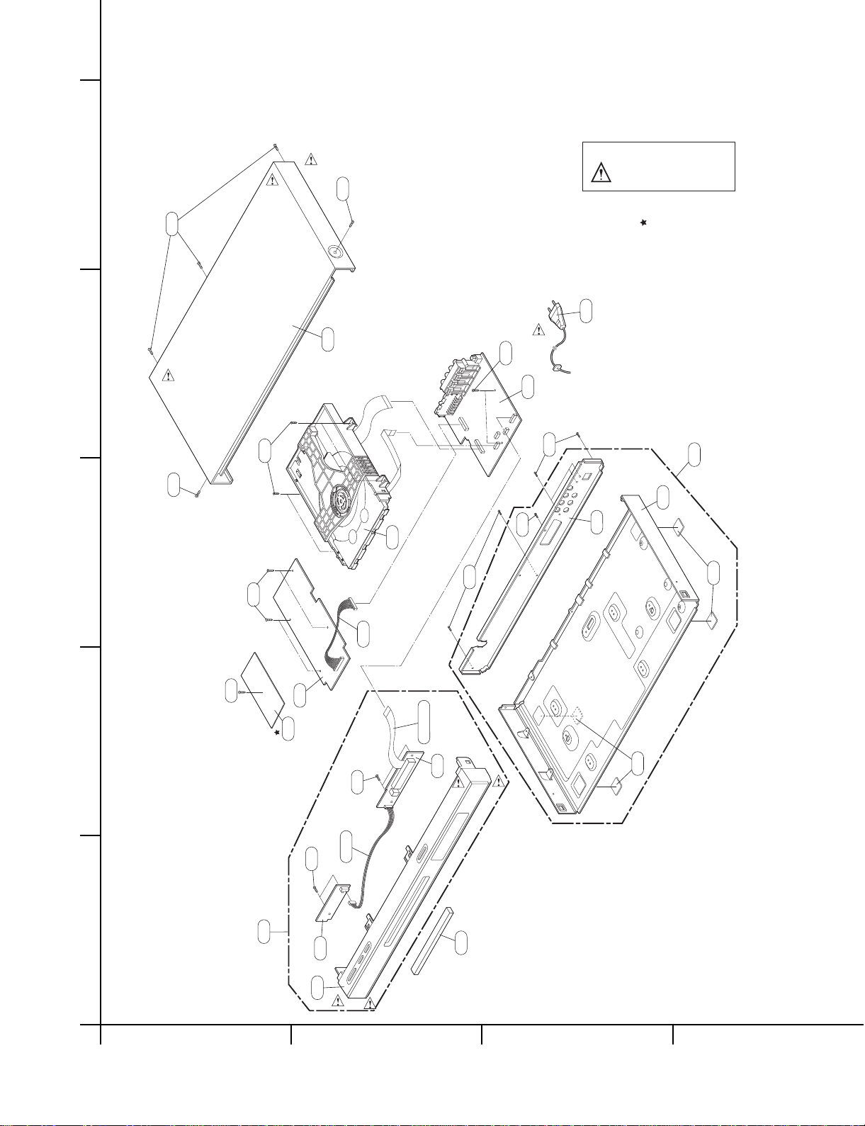
EXPLODED VIEWS
1. Cabinet and Main Frame Section
A
5
4
3
2
1
BCD
463
NOTES) THE EXCLAMATION POINT WITHIN AN
EQUILATERAL TRIANGLE IS INTENDED
TO ALERT THE SERVICE PERSONNEL
TO THE PRESENCE OF IMPORTANT
SAFETY INFORMATION IN SERVICE
LITERATURE.
463
300
250
463
463
A00
463
467
A46
465
320
OPTIONAL PART
A44
260
465
463
261
P101
463
5.1CH, JACK
A47
A48
A43
452
A42
280
CABLE90
A49
452
CN902
283
261
Page 10
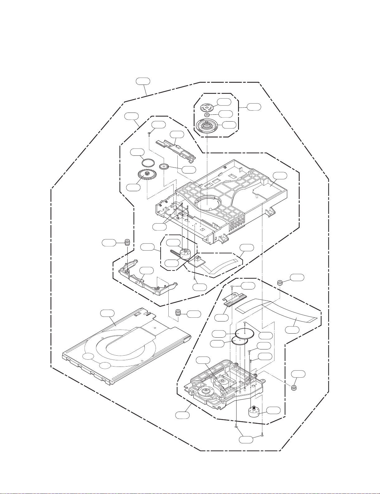
2-3
2. DECK MECHANISM SECTION(DP-10)
A00
012
A02
017
013
015
019
439
435
018
015B
015A
014
440
001
002
A01
003
020
016
012A
432
026
A03
012
036
024
025
030
010
439
431
435
012A
021
430
Page 11
2-4
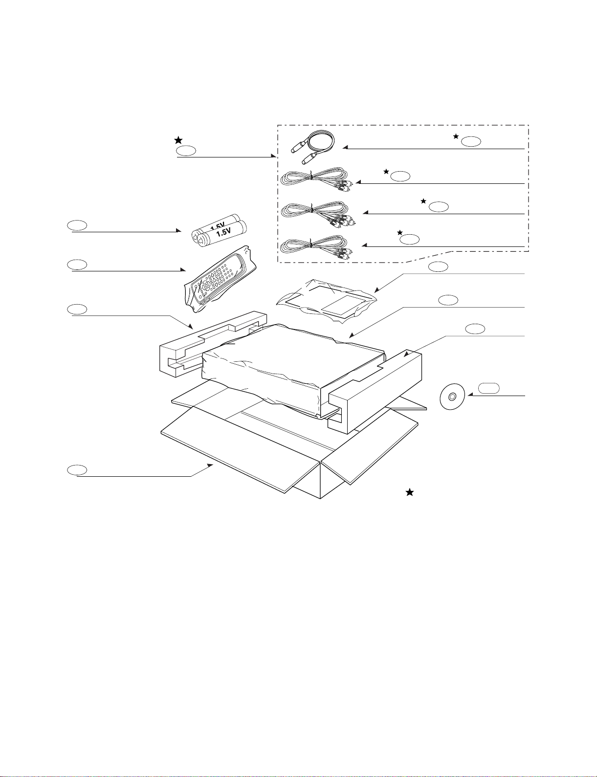
3. PACKING ACCESSORY SECTION
BATTERY
808
PACKING SHEET
804
PACKING
OPTIONAL PARTS
803
806
820
OWNER’S MANUAL
RF CABLE
810
CABLE SET ASS’Y
801
REMOCON
900
BOX CARTON
802
PACKING
803
811
812
PLUG ASS’Y 1WAY(YELLOW)
PLUG ASS’Y 1WAY(BLACK)
PLUG ASS’Y 2WAY
DISC
832
Page 12

3-1
SECTION 3
ELECTRICAL
CONTENTS
ELECTRICAL TROUBLESHOOTING GUIDE......................................................................3-2
1. POWER CHECK FLOW ............................................................................................................3-2
2. SYSTEM OPERATION FLOW ..................................................................................................3-3
3. TEST & DEBUG FLOW ............................................................................................................3-4
4. KARAOKE FLOW (KARAOKE MODEL ONLY).....................................................................3-10
DETAILS AND WAVEFORMS ON SYSTEM TEST AND DEBUGGING ....................3-11
1. SYSTEM 27MHZ CLOCK, RESET SIGNAL. ..........................................................................3-11
2. SDRAM CLOCK......................................................................................................................3-12
3. TRAY OPEN/CLOSE SIGNAL ................................................................................................3-12
4. SLED CONTROL RELATED SIGNAL(NO DISC CONDITION).............................................3-14
5. LENS CONTROL RELATED SIGNAL(NO DISC CONDITION).............................................3-14
6. LASER POWER CONTROL RELATED SIGNAL(NO DISC CONDITION)............................3-15
7. DISC TYPE JUDGEMENT WAVEFORM................................................................................3-15
8. FOCUS ON WAVEFORM........................................................................................................3-17
9. SPINDLE CONTROL WAVEFORM(NO DISC CONDITION...................................................3-18
10. TRACKING CONTROL RELATED SIGNAL(SYSTEM CHECKING)...................................3-19
11. RF WAVEFORM....................................................................................................................3-20
12. ZR36888 AUDIO OPTICAL AND COAXIAL OUTPUT(SPDIF)............................................3-20
13. ZR36888 VIDEO OUTPUT WAVEFORM..............................................................................3-21
14. AUDIO OUTPUT FROM AUDIO DAC ..................................................................................3-22
BLOCK DIAGRAMS..................................................................................................................3-24
1. OVERALL BLOCK DIAGRAM ................................................................................................3-24
2. POWER(SMPS) BLOCK DIAGRAM.......................................................................................3-25
3. SERVO BLOCK DIAGRAM....................................................................................................3-26
4. MPEG & MEMORY BLOCK DIAGRAM .................................................................................3-27
5. VIDEO & AUDIO BLOCK DIAGRAM.....................................................................................3-28
CIRCUIT DIAGRAMS................................................................................................................3-29
1. POWER(SMPS) CIRCUIT DIAGRAM .....................................................................................3-29
2. SYSTEM(MAIN) CIRCUIT DIAGRAM.....................................................................................3-31
3. SERVO CIRCUIT DIAGRAM ..................................................................................................3-33
4. AV/JACKCIRCUIT DIAGRAM.................................................................................................3-35
5. MEMORY CARD CIRCUIT DIAGRAM ...................................................................................3-37
6. TIMER CIRCUIT DIAGRAM ....................................................................................................3-39
7. KARAOKE CIRCUIT DIAGRAM (KARAOKE MODEL ONLY)..............................................3-41
• CIRCUIT VOLTAGE CHART ....................................................................................................3-43
PRINTED CIRCUIT DIAGRAMS............................................................................................3-45
1. MAIN P.C.BOARD...................................................................................................................3-45
2. KEY P.C.BOARD .....................................................................................................................3-47
3. TIMER P.C.BOARD.................................................................................................................3-48
4. SCART P.C.BOARD ............................................................................................................. ...3-49
5. SMPS P.C.BOARD..................................................................................................................3-50
6. KARAOKE P.C.BOARD(KARAOKE MODEL ONLY)(6, 7, 9 TOOL).....................................3-51
Page 13
3-2
ELECTRICAL TROUBLESHOOTING GUIDE
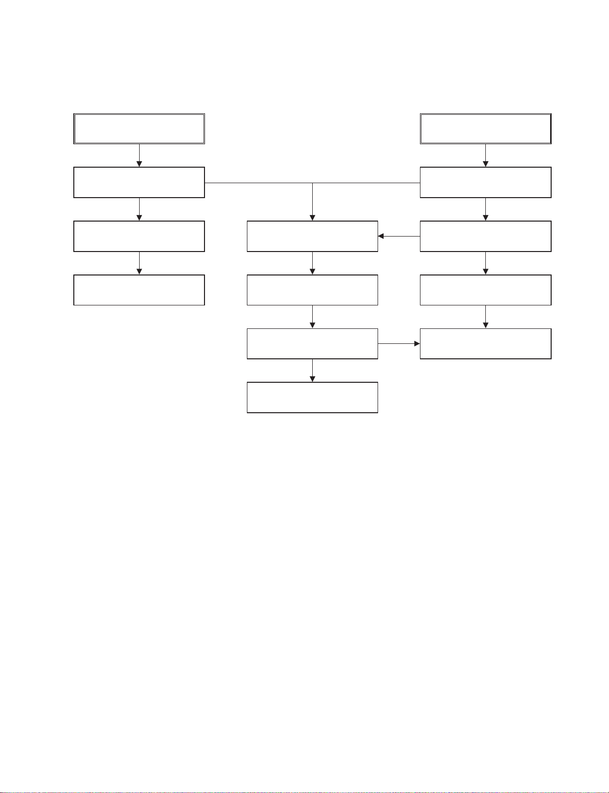
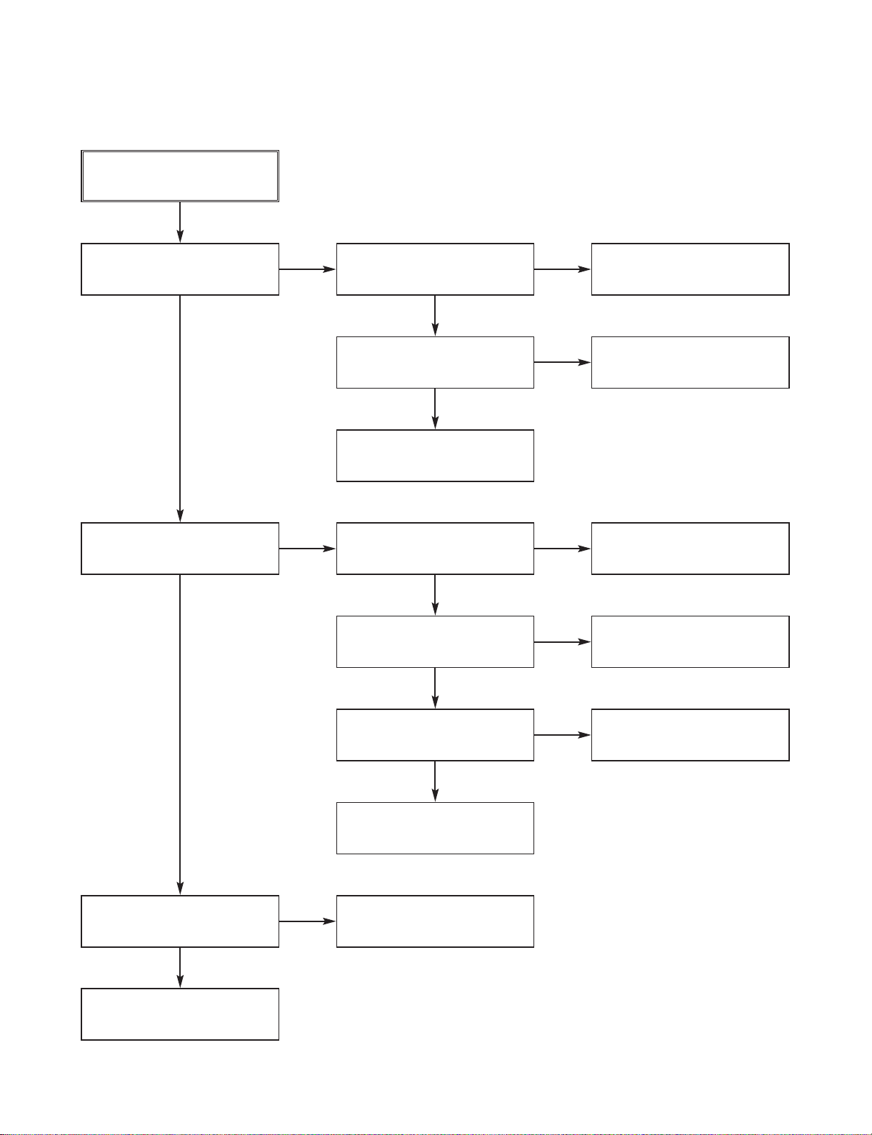
1. POWER CHECK FLOW
No 3.4VA.
No 3.4VA
Is 3.4VA section working?
Is 3.4V present at emitter
of Q121?
Replace Q121.
Replace IC101.
Is there a DC voltage at
Cathode of D105 or D107?
Check FR101
No 5V
Is 3.4VA section working?
Replace Q126.
Is 5.6V present at collector
of Q126?
NO
NO
YES
YES
YES
Check D105/D106/D107/
D108 and replace.
YES
YES
A. B.
NO
NO
NO
Page 14
3-3
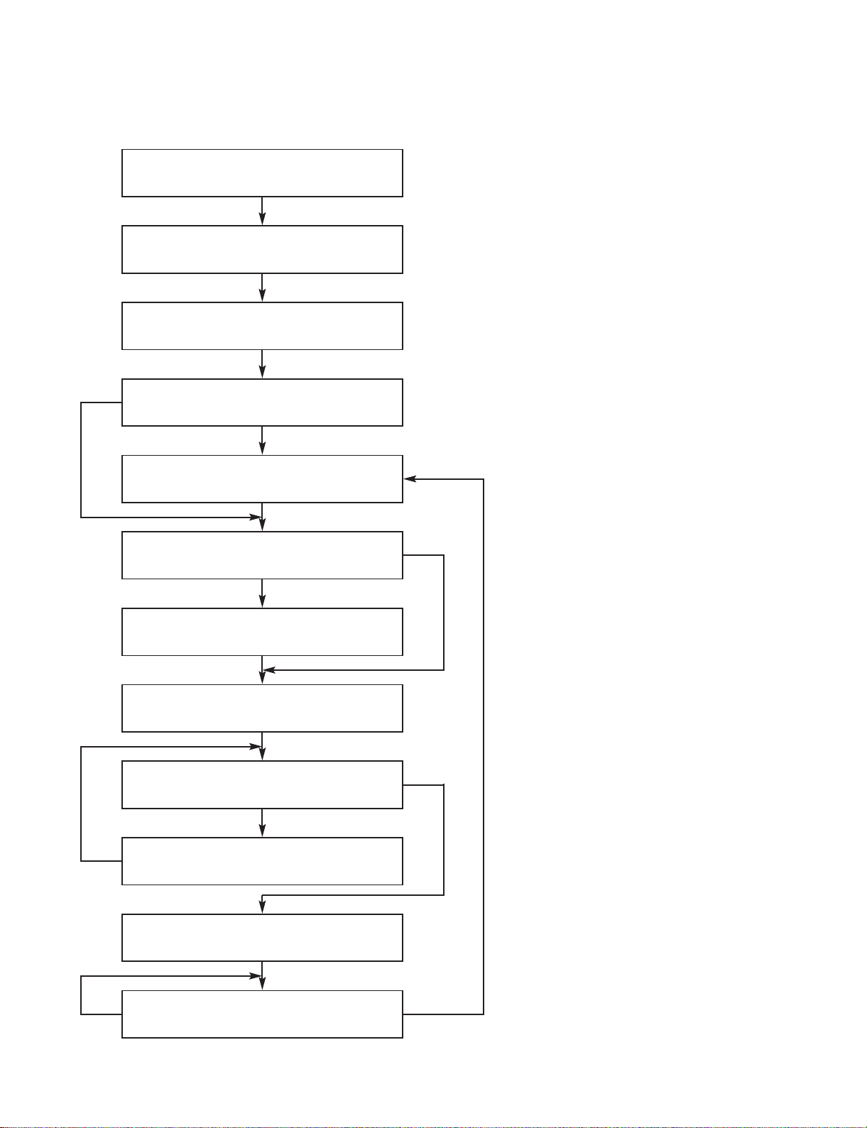
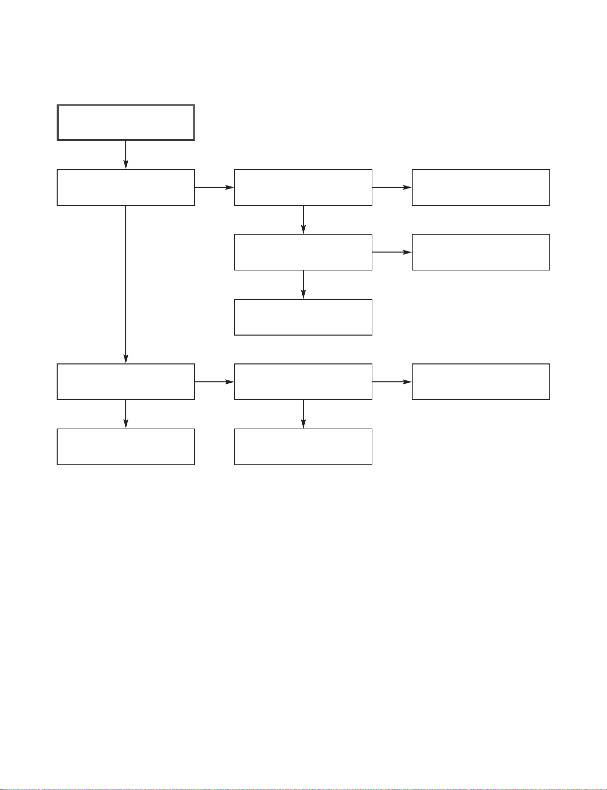
2. SYSTEM OPERATION FLOW
NO
NO
NO
YES
NO
YES
YES
YES
Power On
1. 186 CPU initializes SERVO,DSP & RISC registers
2. Write RISC code to SDRAM
3. Reset RISC
Show LOGO
Tray Closed ?
Tray Close to Closed position
SLED at Inner Side ?
SLED Moves to Inner Position
1. Judge whether have disc and disc type
2. Jump to related disc reading procedure
Recieve OPEN/CLOSE Key?
1. Execute Pressed Key & IR Key
2. System operation Routine Loop
1. Stop Playback & Open Tray
2. Display tray open message & LOGO
Receive CLOSE Key?
Page 15
3-4
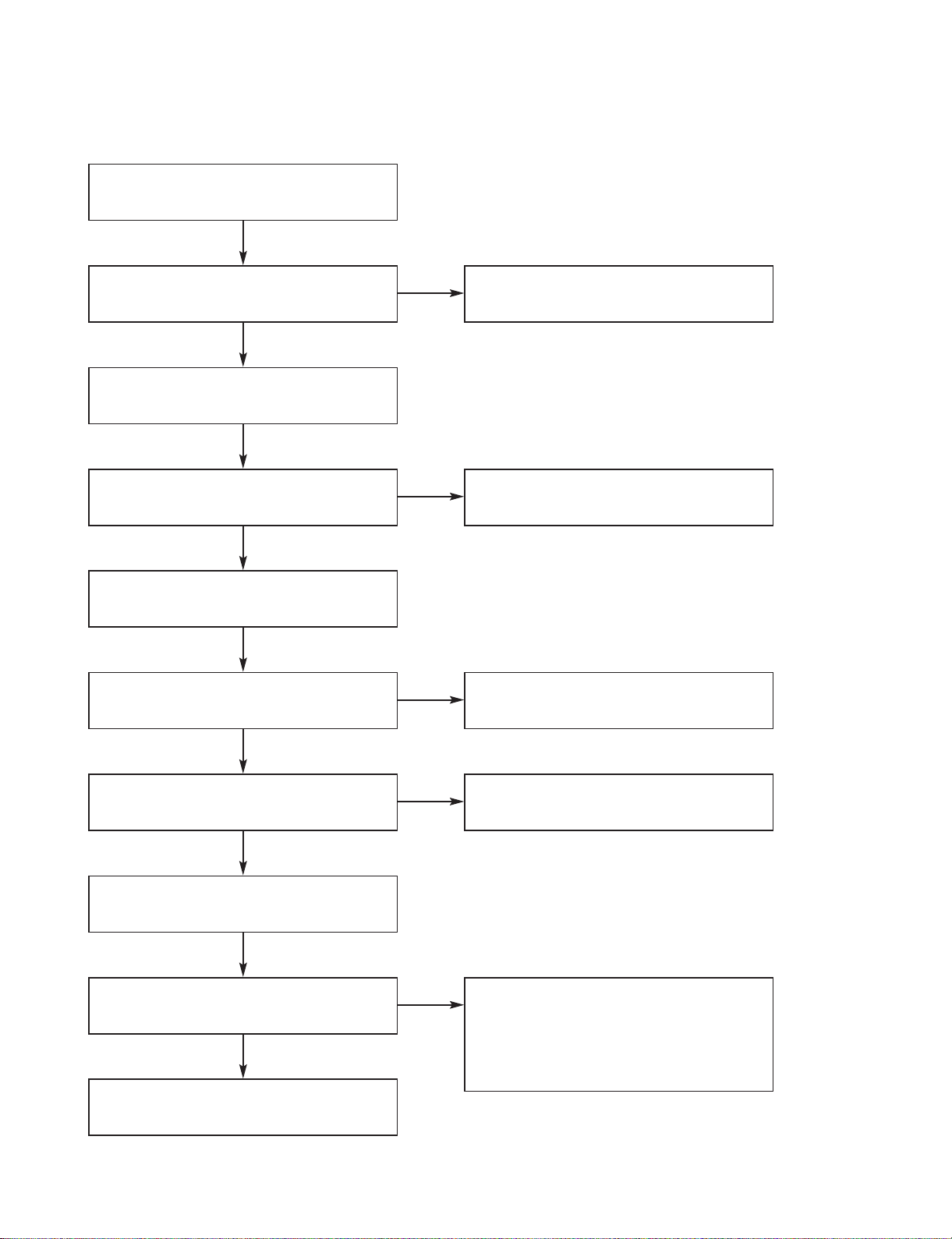
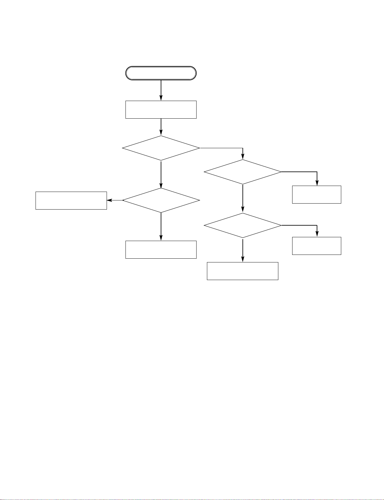
3. TEST & DEBUG FLOW
TEST
Check the AC Voltage
Power PCBA(110V or 220V)
YES
Switch on the Power PCBA
YES
Is the DC Voltage outputs OK?
(5V, 3.3V, 12V, 5.6V MOTOR)
YES
Make sure the main PCBA don't short on
VCCs and switch it on.
YES
Is 3.3V outputs normal on main PCBA?
YES
Connect to PC RS232 Cable and update
the FLASH memory code.
YES
Update FLASH successfully?
YES
A
Replace power PCBA or AC transformer.
NO
Repair or Replace Power PCBA
NO
Check the regulators or related diodes.
NO
Is 1.8V Voltage normal for Zoran IC
YES
1. Check Q203. 2. Check D201.
3. Check IC102
NO
1. Check 27MHz system clock.
2. Check system reset circuit.
3. Check FLASH R/W enable signal PRD,
RWR.
4. Check RS232 SIGNALS.
5. Check FLASH Memory related circuit.
NO
Page 16
3-5
NO
NO
YES YES
YES
YES
YES
YES
YES
YES
YES
NO
NO
NO
NO
NO
NO
NO
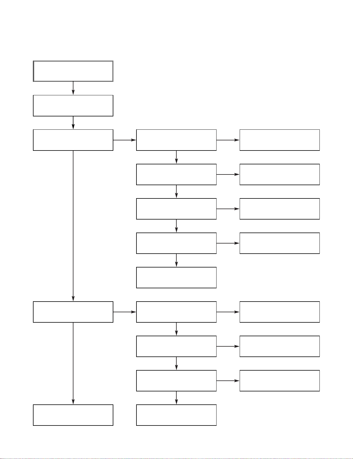
A
RESET or Power On.
Flash Memory operates
properly?
Show LOGO?
Does Tray move inside when
it is not at closed position?
B
Check connection lines between
FLASH & ZR336888 and the FLASH
access time whether is suitable or not.
SDRAM works properly?
Check connection lines
between SDRAM & ZR36888
and the SDRAM is damaged.
ZR36882 VIDEO outputs
properly?
Check the related circuit of
ZR36888
Have TV signal output?
Check AV cable connection
to TV set.
Normal OUTSW & INSW
signals?
Check the filtering and amp
circuit of TV signal.
Check the load OPEN &
CLOSE switch
Normal OPEN & CLOSE
signal?
Check the Tray control IO
pins on ZR36888 &
AM5869S
Normal LOAD+ & LOAD
signal?
Check the cable connection
between main PCBA and
loader.
Check the Tray control
amplifying circuit on Motor
driver.
Page 17

3-6
B
Motor Driver MUTE Pin is
High?
Does the SLED move to
inner side when it is at outter
position?
Do not put in disc and tray
close.
Optical Lens has movements
for searching Focus?
C
NO
NO
YES
YES
YES
YES
YES
YES
Check the connection line of
MUTE signal.
NO
Is SLED_S DC Level higher
than 1.65V?
Check the related circuit of
FMSO.
NO
SLED+ and SLED- output
properly?
YES
Check the amp circuit on
motor driver.
Check FOCUS_S connection
On ZR36888 and motor dirver.
NO
NO
Check the cable connection
with MECHA.
Proper FOCUS_S outputs to
motor driver?
Proper FACT+ & FACT outputs?
Check the amp circuit on
motor dirver.
NO
Check cable connect on with
pick-up head.
Page 18

3-7
C
LD_DVD or LD_CD
output properly?
Laser turns on when
reading disc?
Put disc in?
Disc ID is correct?
Does spindle rotate?
D
NO
NO
NO
NO
YES
YES
YES
YES
YES
YES
Check the laser power circuit
on ZR36888 and connecting
to power transistor.
NO
Collector voltage of power
transistor is OK?
Check the related circuit on
laser power transistor
NO
Check cable connection
between transistor ouput
and pick-up head.
YES
YES
YES
Check the related circuit
on ZR36888 RFL signal.
Check SPINDLE_S related
circuit on ZR36888.
NO
NO
Check the spindle control
amp circuit of motor driver.
NO
Laser off
Proper RF signal on
ZR36888?
Check LD_DVD & LD_CD
signal
Proper SPINDLE_S signal
on ZR36888
SP+ & SP- output properly?
Check the cable connection
between spindle and main
PCBA.
Page 19
3-8
D
Proper signals on A,B,C,D
of ZR36888
Focus ON OK?
Track On OK?
Disc is play ?
E
NO
NO
NO
YES
YES
YES
YES
YES
Check connections between
ZR36888 and pick-up head.
NO
Check FE signal on
ZR36888
YES
Check the FOCUS_S
connection on ZR36888
and motor driver.
NO
Check FOCUS_S signal
on ZR36888
YES
YES
Check the TRACK_S
connection on ZR36888
and motor dirver.
NO
Check the tracking control
amp circuit on motor driver.
NO
Normal TE Signal on
ZR36888?
NO
Check the related
circuit on ZR36888
Properly TRACK_S signal
on ZR36888?
TACT+ & TACT- output
properly?
Check cable connection on
pick-up head.
Check RF signal waveform.
Page 20
3-9
E
Audio DAC received
correct data stream?
Normal Audio output
when disc playback?
Normal IR.VFD & Front
panel key functions?
TEST END
NO
NO
YES
YES
YES
YES
Check connection between
ZR36888 & Audio DAC.
NO
Normal Audio DAC out?
YES
Check the related circuit of
Audio DAC.
NO
Check Audio filter, amplify,
mute circuit.
Communications between
IR.VFD Front panel key &
ZR36888 is normally?
NO
Check communication lines
on ZR36888
Check the cable connection
on Front panel.
Page 21
3-10
4. KARAOKE Flow (KARAOKE MODEL ONLY)
Is the Mic signal at the
IC801 pin3.
Is the Mic signal at the
IC801 Pin 2.
Is the Mic signal at the
IC801 Pins3, 7 normal?
Does the Mic
signal input the IC601
Pin224.
Replace IC601.
Check pattern.
Replace the VR801.
Replace IC801.
Replace the mic jack
Start
Insert the Mic jack
NO
NO
NO
NO
YES
YES
YES
Page 22
3-11
DETAILS AND WAVEFORMS ON SYSTEM TEST AND DEBUGGING
1. SYSTEM 27MHz CLOCK, RESET SIGNAL
1) ZR36882 main clock is at 27MH(X601)
FIG 1-1
3.1V,27MHz
2) ZR3682 reset is low active
FIG 1-2
Reset Time
3.3VA
PWR_CTL
RESET
Page 23
3-12
2. SDRAM CLOCK
1) SDRAM clock is at 143MHz
FIG 2-1
IC603 PIN38
CLK=143MHz,Vp-p=3.3V
3. TRAY OPEN/CLOSE SIGNAL
1) Tray open/close waveform
FIG 3-1
OPEN
OPEN CLOSE
CLOSE
LM-
LM+
Page 24

3-13
2) Tray open waveform
FIG 3-2
3) Tray close waveform
FIG 3-3
OPEN
CLOSE
LM-
LM+
OPEN
CLOSE
LM-
LM+
Page 25

3-14
4. SLED CONTROL RELATED SIGNAL(NO DISC CONDITION)
FIG 4-1
5. LENS CONTROL RELATED SIGNAL(NO DISC CONDITION)
FIG 5-1
FOCUS_S
FOCUS+
FOCUS-
SLED_S
DRVSB
SLED+
SLED-
Page 26

3-15
6. LASER POWER CONTROL RELATED SIGNAL(NO DISC CONDITION)
FIG 6-1
7. DISC TYPE JUDGEMENT WAVEFORM
FIG 7-1(DVD)
DCLK = 128MHz, Vp-p=2.2, Vmax=2.7V
FACT+
FE
SBAD
VR_CD
DVD_LD
CD_LD
Page 27

3-16
FIG 7-2 (DVD)
FIG 7-3 (CD)
FACT+
FACT+
FE
FE
SBAD
SBAD
Page 28

3-17
FIG 7-4 (CD)
8. FOCUS ON WAVEFORM
FIG 8-1 (DVD)
FE
FOSO
FACT+
FACT-
FACT+
FE
SBAD
Page 29

3-183-18
FIG 8-2 (CD)
9. SPINDLE CONTROL WAVEFORM(NO DISC CONDITION)
FIG 9-1 (DVD)
FOCUS
FACT+
SPINDLE_S
SP+
SP-
FE
FACT-
Page 30

3-19
10. TRACKING CONTROL RELATED SIGNAL(System checking)
FIG 10-1 (DVD)
FIG 10-2 (CD)
TE
TRACK_S
TACT+
TACT-
TE
TRACK_S
TACT+
TACT-
Page 31

3-20
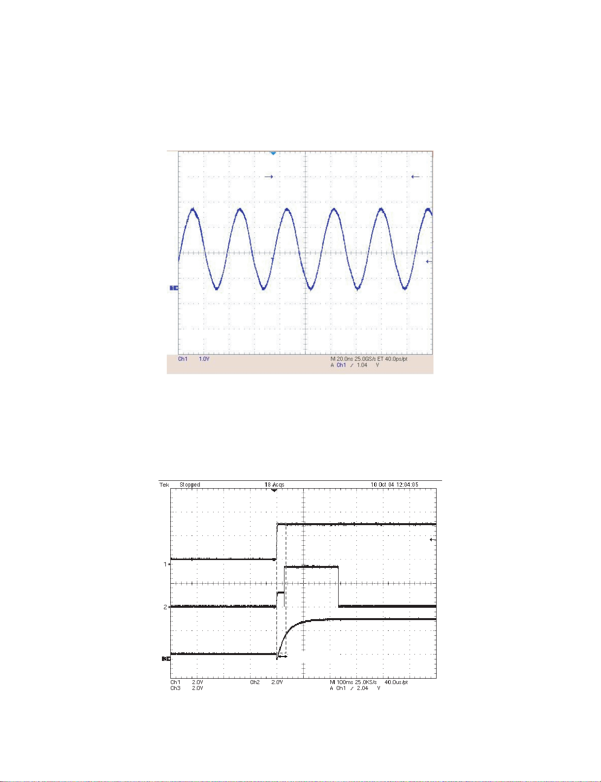
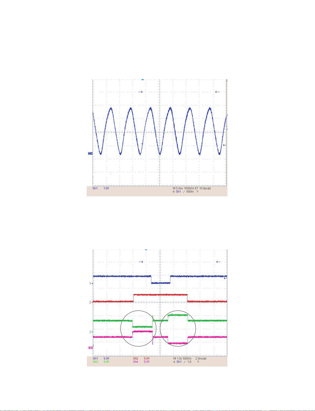
11. RF WAVEFORM
FIG 11-1
12. ZR36888 AUDIO OPTICAL AND COAXIAL OUTPUT(SPDIF)
FIG 12-1
RFO
SPDIF
Page 32

3-21
13. ZR36888 VIDEO OUTPUT WAVEFORM
1) Full colorbar signal(CVBS)
FIG 13-1
2) Y
FIG 13-2
JK701 pin3
JK701 pin9
Page 33

3-22
14. AUDIO OUTPUT FROM AUDIO DAC
1) AUDIO L/R
FIG 14-1
3) C
FIG 13-3
JK701 PIN10
JK702 PIN2, 4
1KHz 0DB
Page 34

3-23
2) Audio Related Signal
FIG 14-2
AOUT0
ABCK
ALRCLK
Page 35

3-24
BLOCK DIAGRAMS
1. OVERALL BLOCK DIAGRAM
L
F
T
M
S
D5V
IC605
EEPROM
AT24C08A
CN101
DUPTD0
AD_I/F
DOWN_LO
KARAOKE
DD 5.1CH
WOOFER
SL
SR
RL
RR
FL
FR
IC702
CS4392
OP-AMP
L
R
HDMI5V
33
DSPVCC
FVCC33
3.3VA,5V
CN607
JK705
HDMI_T
I603
64M bit
IC604
I/F AUX
Flash Card
YPE_A
SDRAM
ROM
FLASH
DUPRD0
I2CDATA
ROMDATA[0:15]
ROMADD[0:11]
MEMWR
MEMRD
DSPVCC18
MEMADD[0:20]
I2CCLK
RAMCAS
RAMRAS
RAMCS1
DSPVCC33
IC601
RAMCS0
RAMBA
RAMWE
RF+DSP+
MPEG IC
FCU_IRQ,FCU_CS3
FCU_WAIT,FCU_RST
FCU_SCLK,FCU_IORD#
CARD_SEL.IDE_RST
CARD_DETECT
I2CCLK I2CDAT
TMDS CLK
TMDS D(0:2)
ROMDAT[00:15]
ZR36888
RAMCKE
PCLK
AMCLK
ALRCLK
ABCLK
AOUT3
MIIRXD(0:3)
MIITXDV,MIITXCLK
MIITXD(0:3)
MIITXEN,MIITXER
USB_DN
USB_DP
27MHz
RESET
RESET
DMUTE
CN610
Circuit
D. DATA
D.CLK
D.ENA
COAXIAL
R/Pr
G/Y
B/Pb
CVBS
To USB2.0
Board
IR Receiver
To Front IC
DISC
DVD : A,B,C,D,RF
CD : A,B,C,D,E,F,RF
DECK
MECHANISM
CD DVD SW
CDMD,DVDMD
CDLD,DVDLD,VC(2.1V)
Pick-up
PICK
UP
M
MOTOR
SPINDLE
SLED
(FEEDING)
M
M
LOADING
MOTOR
CD_DVD
MOTOR
ADC_H
U204
LM393
OCUS[+,-]
RACK[+,-]
LED[+,-]
HOMESW
INSW,OUTSW
SPDL_SENS(+,-)
5
OT SPDL[+,-]
OAD[+,-]
V
SLED_S,SPINDLE_S,FOCUS_S,TRACK_S
DRVSB
OPEN,CLOSE
U202
AM5869(5Ch)
Motor Drive
POWER CTL
D5V
M5V
+12V
3.3V
3.3VA
POWER
AC 90V~240V
50HZ/60Hz
GND
BOARD
Page 36

3-25
2. POWER(SMPS) BLOCK DIAGRAM
LPF
12V
5V
LPF
5.6V(M)
/ 5.6VA
T/ W
8V
REG.
LPF
3.2V
3.4VA
PWR CTL
RECTIFIER(14V)
RECTIFIER(5.6V)
TRANS
SWITCHING IC
FILTER
RECTIFIER(9.5V)
RECTIFIER
RECTIFIER(3.4V)
FEED B.
AC100~240V
Page 37

3-26
3. SERVO BLOCK DIAGRAM
ROM
FLASH
MEMDA[0:15]
MEMAD[0:19]
MEMWR,MEMRD
MEMCS
X601
27MHz
X-TAL
IC601
EEP
ROM
I2CCLK
ZR36888
DVDPLAYER
I2CDAT
ONE CHIP
RS232C(MTK)
DUPTD0
DUPTR0
RAMCKE
PCLK,RAMBA
RAMCS1,RAMWE
RAMCAS,RAMRAS
RAMADD[0:11]
RAMDQM,
IC603
SDRAM
RAMDAT[0:15]
4M x 16bit
SPDL_SENS+ ,1.8VA
OPEN,CLOSE,SLED_S,SPINDLE_S,
FOCUS_S,TRACK_S, DRVSB
IC201
AM5869S
Motor Dr iver
ALPC
V20, PICKSEL
VR_DVD,VR_CD
CD_LD,DVD_LD
CD_DVD
DVD: A,B,C,D, RFO
UP
PICK
CD: A,B,C,D, E, F,RFO
TRIN,TROUT
FACT+, FACT-
TACT+, TACT-
SLED+, SLED-
SP+, SP-
M/D
LOAD+, LOAD-
Page 38

3-27
4. MPEG & MEMORY BLOCK DIAGRAM
VIDEO
Interface
IC605
EEPROM
C_Y,S_Y
SY_Pr_OUT,Y_OUT,SC_Pb_out
I2CCLK/MC
I2CDAT/MD
RGB_SEL,16_9_H
AMCLK,ALRCK,ABCK
AUDIO
I2CCLK/MC, I2CDAT/MD
D_MUTE
AOUT0.ML
Interface
ASPDIF
MEMDA[0:15]
MEMAD[0:19]
IC604
MEMRD
MEMWRFLASHCS-
(16 M )
FLASH MEMORY
IC603
SDRAM
ZR36888
RAMDQM ,RAMWE
PCLK ,RAMBA,RAMCS1
64M
RAMAD[00:11] ,RAMCKE
RAMDAT[00:15]
RAMRAS
RAMCAS
IC601 (MPEG + DSP + RF)
X601
27MHz
CLK,STB
DIN ,DOUT
IC901
LED DRIVE IC
RESET
IC606
RESET IC
Page 39

3-28
5. VIDEO & AUDIO BLOCK DIAGRAM
M
A/V
JACK
AUDIO "L"
AUDIO "R"
CVBS
SUPER VIDEO (Y/C)
COMPONENT (R.G.B) / (Y.Pb.Pr )
Amp
IC701
VIDEO 6dB
IC703 (OP Amp)
LPF&Buffer
IC702
(2CH)
AUDIO DAC
(C_Y/S_Y)
(SY_Pr_OUT,Y_OUT,SC_Pb_OUT )
MPEG
ML
ABCK
AMCLK
PEG
ALRCK
AOUT3
Page 40

3-29 3-30
CIRCUIT DIAGRAMS
1. POWER(SMPS) CIRCUIT DIAGRAM
IMPORTANT SAFETY NOTICE
WHEN SERVICING THIS CHASSIS, UNDER NO CIRCUMSTANCES SHOULD THE ORIGINAL DESIGN BE
MODIFIED OR ALTERED WITHOUT PERMISSION
FROM THE NAD ELECTRONICS CORPORATION. ALL
COMPONENTS SHOULD BE REPLACED ONLY WITH
TYPES IDENTICAL TO THOSE IN THE ORIGINAL CIR-
CUIT. SPECIALCOMPONENTS ARE SHADED ON THE
SCHEMATIC FOR EASY IDENTIFICATION.
THIS CIRCUIT DIAGRAM MAY OCCASIONALLY DIFFER FROM THE ACTUAL CIRCUIT USED. THIS WAY,
IMPLEMENTATION OF THE LATEST SAFETY AND
PERFORMANCE IMPROVEMENT CHANGES INTO
THE SET IS NOT DELAYED UNTILTHE NEW SERVICE
LITERATURE IS PRINTED.
NOTE :
1. Shaded( ) parts are critical for safety. Replace only
with specified part number.
2. Voltages are DC-measured with a digital voltmeter
during Play mode.
12
11
No Power
D105~D108 is Defective
14VA No Power
D125 is Defective
12V No Power
Q123 is Defective
5.0V No Power
10
9
8
7
5.6VA No Power
D123 is Defective
Switching Error
Q126 is Defective
5.6V No Power
Q125 is Defective
IC101is Defective
6
5
4
3
2
NOTES) Symbol denotes AC ground.
1
NOTES) Symbol denotes DC chassis ground.
A
3.3V No Power
No Power
FR101 is Defective
3.3VA No Power
D121 or D122 are Defective
Q121 is Defective
Switching Error
IC102,IC103 are Defective
OPTIONAL PART
NOTE) Warning
NOTE) Parts that are shaded are critical
NOTE) With respect to risk of fire or
NOTE) electricial shock.
B C D E F G H I J K L M N O P Q R ST
Page 41

3-31 3-32
2. SYSTEM(MAIN) CIRCUIT DIAGRAM
A
1
2
3
4
5
6
7
8
9
10
11
12
B C D E F G H I J K L M N O P Q R ST
Page 42

3-33 3-34
A
1
2
3
4
5
6
7
8
9
10
11
12
B C D E F G H I J K L M N O P Q R ST
3. SERVO CIRCUIT DIAGRAM
Page 43

3-35 3-36
4. AV/JACK CIRCUIT DIAGRAM
A
1
2
3
4
5
6
7
8
9
10
11
12
B C D E F G H I J K L M N O P Q RST
Page 44

3-37 3-38
5. MEMORY CARD CIRCUIT DIAGRAM
A
1
2
3
4
5
6
7
8
9
10
11
12
B C D E F G H I J K L M N O P Q RST
Page 45

3-39 3-40
6. TIMER CIRCUIT DIAGRAM(9TOOL)
A
1
2
3
4
5
6
7
8
9
10
11
12
B C D E F G H I J K L M N O P Q R ST
Page 46

3-41 3-42
7. KARAOKE CIRCUIT DIAGRAM (KARAOKE MODEL ONLY)
A B C D E F G H I J K L M N O P Q R ST
Page 47

• CIRCUIT VOLTAGE CHART
(PLAY)
+/A
(PLAY)
-/K
MODE
condenser
C686 4.89 0.00
C214 5.69 0.00
C201 4.90 0.00
C217 1.79 0.00
C208 3.25 2.37
C6E6 3.25 0.00
C223 3.25 0.00
C6B2 12.06 0.00
C6B3 5.52 0.00
C209 3.25 3.12
C6K2 4.88 0.00
C6A4 3.25 0.00
C6F7 3.26 0.00
C6J1 3.25 0.00
C6A2 3.25 0.00
C6A7 1.78 0.00
C6E2 3.24 0.00
C6E3 3.24 0.00
C6A5 1.78 0.00
C7C2 12.06 0.00
C7E4 4.84 0.00
C7E5 2.42 0.00
C7E8 5.55 0.00
(PLAY)
+/A
(PLAY)
-/K
MODE
condenser
C787 4.90 0.00
C7C1 5.54 0.00
C7E2 4.89 0.00
C7C3 5.55 0.00
C7E6 5.55 2.45
C7E9 5.54 2.45
C727 2.45 0.00
C6E1 3.25 0.00
C6C9 3.25 0.00
C7E1 4.92 0.00
C6A1 1.79 0.00
C6E4 1.76 0.00
C6E5 3.26 0.00
C6A6 3.26 0.00
C741 4.88 0.00
C686 4.93 0.00
C731 1.24 1.00
C782 1.85 0.26
C783 2.30 0.00
C784 1.20 0.00
C785 2.31 0.00
D601 3.255 3.257
D201 3.242 2.453
STOP PLAY
MODE
1 1.68 1.82
2 1.84 1.82
3 0.8 0.84
4 1.68 1.68
5 1.28 1.32
6 0.007 0.023
7 0.008 0.026
8 5.76 5.72
9 0.003 0.008
10 0.003 0.0068
11 2.84 2.98
12 2.84 2.8
13 2.76 3.3
14 2.76 3.34
15 2.82 3.46
16 2.82 3.18
17 1.66 3.6
18 1.68 2.16
19 5.76 5.72
20 1.128 1.52
21 5.76 5.7
22 0.006 0.0052
23 1.66 1.96
24 0.488 0.48
25 5.52 5.52
26 1.66 1.64
27 1.66 1.64
28 0.012 3.12
1 0.01 0.01
2 0.008 0.009
3 0.006 0.007
4 0.026 0.028
5 0.006 0.008
6 3.32 3.3
7 2.8 3.24
8 3.34 3.32
9 3.32 3.3
10 3.34 3.32
11 3.34 3.32
12 3.34 3.34
13 3.34 3.32
14 3.34 3.34
15 3.34 3.32
16 3.34 3.32
17 3.34 3.34
18 3.34 3.3
19 3.34 3.34
20 3.32 3.3
21 0.01 0.012
22 3.34 3.32
23 3.36 3.3
24 3.34 3.34
25 3.32 3.32
STOP PLAY
MODE
PIN NO.
26 3.34 3.34
27 3.32 3.32
28 3.32 3.32
29 3.3 3.3
30 3.34 3.34
31 3.32 3.32
32 3.36 3.36
33 3.3 3.3
34 1.82 1.82
35 3.32 3.32
36 3.32 3.3
37 3.3 3.3
38 0.0024 0.003
39 3.32 3.32
40 3.3 3.3
41 0.0031 0.004
42 3.32 3.32
43 3.34 3.34
44 3.34 3.34
45 3.34 3.34
46 3.32 3.32
47 3.34 3.34
48 3.34 3.34
49 3.34 3.34
50 3.34 3.34
51 3.34 3.34
52 3.34 3.34
53 3.34 3.34
54 3.34 3.34
55 3.34 3.34
56 3.34 3.34
57 3.34 3.34
58 3.3 3.28
59 0.004 0.005
60 0.0024 3.32
61 3.34 3.32
62 2.36 2.34
63 3.16 3.12
64 3.32 3.32
65 3.34 3.32
66 0.001 0.002
67 0.0013 0.0015
68 0.0023 0.003
69 3.32 3.32
70 3.32 3.32
71 3.32 3.32
72 3.32 3.3
73 3.32 3.32
74 3.34 3.34
75 3.32 3.34
76 3.34 3.3
77 3.32 3.3
78 0.01 0.009
79 3.3 3.3
80 1.82 1.8
STOP PLAY
MODE
PIN NO.
81 3.34 3.32
82 0.014 0.016
83 3.3 3.3
84 3.34 3.34
85 3.32 3.32
86 3.34 3.34
87 3.32 3.3
88 0.002 0.005
89 3.34 3.34
90 3.34 3.32
91 3.34 3.34
92 3.34 3.32
93 3.34 3.34
94 0.0028 0.003
95 0.0012 0.002
96 1.96 1.96
97 3.48 3.34
98 3.28 3.28
99 0.005 0.009
100 3.36 3.32
101 3.38 3.34
102 3.38 3.32
103 3.34 3.32
104 3.38 3.34
105 3.38 3.32
106 3.36 3.34
107 0.0099 0.01
108 1.96 1.98
109 1.82 1.8
110 3.36 3.32
111 0.009 0.01
112 3.36 3.32
113 3.34 3.34
114 3.4 3.32
115 3.38 3.32
116 3.38 3.32
117 0.008 0.01
118 3.38 3.32
119 3.38 3.3
120 3.38 3.32
121 3.34 3.32
122 3.92 3.96
123 0.008 0.01
124 0.016 3.32
125 0.012 0.014
126 3.32 3.3
127 0.032 0.03
128 0.032 0.01
129 0.024 3.32
130 0.0258 0.03
131 3.34 3.32
132 3.34 3.32
133 0.0048 0.005
134 3.26 3.24
135 3.34 3.34
STOP PLAY
MODE
PIN NO.
136 0.02 0.022
137 0.007 0.01
138 3.34 3.32
139 0.006 0.009
140 0.011 0.14
141 3.34 3.38
142 0.013 0.1
143 0.013 0.28
144 0.013 0.015
145 0.014 0.14
146 0.0059 0.006
147 1.82 1.82
148 0.013 0.02
149 0.013 0.015
150 0.013 0.014
151 0.012 0.01
152 0.01 0.01
153 0.01 0.01
154 3.34 3.34
155 0.005 0.006
156 0.005 0.007
157 3.32 3.32
158 1.84 1.82
159 2.38 2.38
160 1.66 1.86
161 1.84 1.84
162 0.005 0.008
163 0.0053 0.007
164 0.005 0.007
165 0.0058 0.007
166 3.34 3.32
167 0.0056 0.008
168 0.0048 0.0048
169 0.0048 0.0048
170 0.0054 0.0054
171 0.0052 0.0054
172 3.34 3.32
173 0.0052 0.005
174 0.0054 0.005
175 0.005 0.0048
176 1.064 1.1
177 0.0044 0.005
178 1.86 1.84
179 0.0052 0.006
180 0.0052 0.006
181 1.16 1.08
182 3.28 3.3
183 2.22 2.06
184 0.8 0.6
185 3.32 3.3
186 1.58 1.54
187 0.82 0.5
188 3.32 3.3
189 0.88 0.78
190 1.3 1.3
STOP PLAY
MODE
PIN NO.
IC201
IC601
191 0.005 0.006
192 0.005 0.004
193 1.33 1.86
194 1.328 1.36
195 0.104 0.14
196 2.2 2.34
197 3.32 3.3
198 2.2 2.5
199 3.32 3.3
200 3.32 3.3
201 2.2 2.4
202 0.14 0.14
203 2.2 2.34
204 0.16 0.14
205 0.005 0.006
206 2.16 2.16
207 0.56 0.48
208 2.16 2.18
209 2.22 2.22
210 1.4 1.38
211 1.38 1.38
212 0.006 0.007
213 0.0072 0.24
214 3.14 3.14
215 3.16 2.36
216 0.0044 0.005
217 0.0064 0.005
218 1.72 1.7
219 0.0064 0.005
220 0.0046 0.007
221 3.32 3.32
222 0.034 0.1
223 3.34 3.32
224 0.0044 0.005
225 0.005 0.006
226 0.0048 0.006
227 0.0042 0.007
228 3.34 3.34
229 0.0064 0.006
230 0.01 0.009
231 3.18 3.28
232 0.029 0.03
233 0.0074 0.008
234 3.18 3.32
235 3.43 3.32
236 0.016 3.14
237 3.18 3.3
238 3.18 3.3
239 0.026 0.03
240 3.1 3.08
241 0.0072 0.005
242 3.34 3.32
243 0.0064 0.006
244 0.091 0.14
245 3.34 3.34
STOP PLAY
MODE
PIN NO.
IC603
246 3.34 0.14
247 0.0052 0.005
248 3.22 3.22
249 0.01 0.005
250 0.0048 0.007
251 0.036 0.004
252 0.02 0.004
253 0.019 0.02
254 3.16 3.26
255 3.28 3.36
256 0.0048 0.005
1 3.36 3.34
2 3.34 3.34
3 3.34 3.34
4 3.34 3.34
5 3.34 3.34
6 0.0088 0.014
7 3.34 3.34
8 3.34 3.34
9 3.34 3.34
10 3.34 3.34
11 3.32 3.32
12 0.0072 0.017
13 3.32 3.32
14 3.34 3.34
15 3.3 3.3
16 3.34 3.34
17 3.34 3.34
18 3.34 3.34
19 3.34 3.34
20 3.32 3.32
21 3.32 3.32
22 3.34 3.34
23 3.32 3.32
24 3.32 3.32
25 3.34 3.34
26 3.32 3.32
27 3.38 3.38
28 0.01 0.0088
29 3.32 3.32
30 3.32 3.32
31 3.32 3.32
32 3.32 3.32
33 3.32 3.32
34 3.3 3.3
35 3.32 3.32
36 0.008 0.0096
37 3.32 3.32
38 1.94 1.94
39 0.035 3.34
40 0.003 0.007
41 0.0064 0.008
42 3.36 3.32
43 3.36 3.34
PLAY
E/S
PLAY
C/D
PLAY
B/G
MODE
PIN NO.
Q601 0.02 0.00 0.03
Q602 0.00 0.00 0.63
Q603 0.00 4.39 0.03
Q701 3.28 0.00 3.27
Q702 0.00 0.00 0.00
Q703 0.00 0.00 0.01
Q704 0.00 0.00 0.00
Q705 0.00 3.27 0.00
Q706 0.00 0.00 0.00
Q715 3.27 0.04 0.03
Q716 3.27 0.04 0.03
PIN NO.
3-43 3-44
STOP PLAY
MODE
PIN NO.
IC605
IC608
IC609
IC701
IC702
44 3.32 3.32
45 3.34 3.32
46 0.017 0.005
47 3.34 3.34
48 3.34 3.34
1 0.017 0.006
2 0.017 0.0056
3 0.017 0.0056
4 0.017 0.0056
5 2.36 2.34
6 3.16 3.14
7 0.017 0.0056
8 3.36 3.34
1 4.8 4.8
2 2.52 2.52
3 3.32 3.32
4 2.08 2.04
5 2.08 2.08
6 0.03 0.0064
7 4.96 4.96
8 2.1 2.08
1 0.03 0.01
2 5.56 5.56
3 5.52 5.52
4 0.015 0.0056
5 0.013 0.01
6 5.56 5.56
7 12.24 12.8
8 0.004 0.008
1 4.96 4.96
2 2.04 2.04
3 2.48 2.48
4 2.44 2.28
5 4.96 4.96
6 2.12 2.04
7 0.007 0.0048
8 2.88 2.66
9 2.82 2.62
10 0.007 0.005
11 3.76 3.5
12 3.8 3.56
13 2.6 2.24
14 3.28 3.08
15 3.28 3.04
16 2.36 2.36
1 3.2 3.02
2 0.0192 0.005
3 3.34 3.28
4 0.0084 0.006
5 0.001 0.001
STOP PLAY
MODE
PIN NO.
IC703
6 4.88 4.88
7 2.64 2.64
8 2.68 2.64
9 0.006 0.005
10 2.46 2.44
11 4.48 4.52
12 4.48 4.52
13 2.2 2.2
14 3.12 3.12
15 0.011 0.004
16 2.1 2.08
1 5.68 5.6
2 5.68 5.6
3 5.68 5.6
4 0.0046 0.004
5 5.56 5.6
6 5.6 5.6
7 5.6 5.8
8 12.24 12.24
STOP PLAY
MODE
PIN NO.
IC604
44 3.36 3.34
45 3.36 3.34
46 0.006 0.007
47 3.36 3.34
48 3.36 3.34
49 3.36 3.34
50 3.36 3.34
51 3.34 3.32
52 0.005 0.007
53 3.34 3.32
54 0.005 0.0064
1 3.32 3.34
2 3.32 3.34
3 3.28 3.34
4 3.28 3.34
5 3.28 3.34
6 3.28 3.34
7 3.32 3.34
8 3.28 3.36
9 3.28 3.32
10 0.011 0.007
11 3.36 3.38
12 3.34 3.34
13 3.34 3.34
14 3.34 3.34
15 0.013 0.005
16 3.3 3.32
17 3.34 3.36
18 3.34 3.32
19 3.34 3.34
20 3.32 3.32
21 3.34 3.34
22 3.32 3.34
23 3.34 0.005
24 3.3 3.3
25 3.3 3.3
26 3.34 3.34
27 0.014 0.005
28 3.34 3.34
29 3.32 3.34
30 3.3 3.32
31 3.32 3.36
32 3.32 3.32
33 3.32 3.32
34 3.32 3.32
35 3.3 3.32
36 3.34 3.32
37 3.34 3.34
38 3.32 3.32
39 3.32 3.3
40 3.3 3.32
41 3.32 3.32
42 3.32 3.32
43 3.34 3.34
Page 48

3-45 3-46
PRINTED CIRCUIT DIAGRAMS
1. MAIN P.C.BOARD
( TOP VIEW ) ( BOTTOM VIEW )
Page 49

3-47 3-48
2. KEY P.C.BOARD 3. TIMER P.C.BOARD
( TOP VIEW )
( BOTTOM VIEW )
( TOP VIEW )
( BOTTOM VIEW )
Page 50

3-49 3-50
5. SMPS P.C.BOARD
4. SCART P.C.BOARD
( TOP VIEW )
( BOTTOM VIEW )
NOTES) Warning
NOTES) Parts that are shaded are critical
NOTES) with respect to risk of fire or
NOTES) electricial shock.
Page 51

3-51 3-52
6. KARAOKE P.C.BOARD(KARAOKE MODEL ONLY)(6, 7, 9 TOOL)
Page 52

NOTES)
If you want to purchase
Flash memory, you must order
" IC604A"
NOTES)
Warning
Parts that are shaded are critical with
respect to risk of fire or electrical
shock.
SECTION REPLACEMENT PARTS LIST
MODEL :
T515C(NAD)
4a
RUN DATE : 04-JULY-06
SALLOCA. NO. PART NO. DESCRIPTION SPECIFICATION REMARKS
*** INDIVIDUAL PARTS ***
250 3110R-D036A Case DVN15 PRESS NAD
283 3580R-T229A Door,Case DVD DVN15 MOLD NAD
300 6410RCHX03A Power Cord Assembly CE-503/JL201B H03VVH2-F 0.75/2
463 1SZZR-0098G Screw,Customzied - + 3MM 8MM MSWR FZW
465 1SZZR-0097K Screw,Customzied - + 3MM 10MM MSWR FZB SIN JIN
801 3835RD0098Z Manual Assembly DVD DVN156NH-HA1UNN/DVN156EH-H
802 3890R-C420D Box,Master DVN156EH HA6ENN SW3-A GRAY
803 3920R-E227A Packing DVD DVN15 1 NAD
804 3880R-E002A Bag,Vinyl CUTTING HDPE 430 500 0.5 DVD90 NSP
808 6910A90004A Battery,Alkaline R03P 1500MV 4AH AAA
808 841-0021 Battery,Manganese ER03X 1500MV 500MAH AAA ALTERNATE
900 6711R2N124C Remote Controller Assembly NAD DVN156 NAD
*** Board Assembly ***
A43 3501RF9903D Board Assembly DVD DVN156EH HA6ENN FRONT(D/GR
280 3721R-F465D Panel Assembly,Front DVD DVN156EH HA6ENN NAD (D/GRA NSP
452 1SZZR-0098A Screw,Customzied - + 3MM 10MM MSWR FZY SIN JIN
A49 6871R-9634A PCB Assembly DVD100S NAD MODEL TIMER SH
C901 0CE2274C638 Capacitor,AL,Radial ESS227M6R3T1A5E07G 220uF 20% 6
C902 0CE4764C638 Capacitor,AL,Radial ESS476M6R3T1A5C07G 47uF 20% 6.
CN902 6631R-E0349 CONNECTOR ASSEMBLY GIL-S/9073ST 8PIN 220M/M 10000
CN903 6630R-FB05L Conector,FFC/FPC/PIC 00-6232-012-104-800 12P 1.00MM
DIG901 6301R2U017G LED Assembly TOS-2604AW-B4 OASIS LED CLOCK
RC901 6712R1238HA Receiver Module AT138ARF1(346HF6N2-B) 2.7TO6V
SW901 6600R000036 Switch,Tact EVQ22505R 1C1P 15VDC 0.02A VER
SW901 6600R000039 Switch,Tact TSH-2VT 1C1P 12VDC 0.05A VERTI ALTERNATE
SW907 6600R000036 Switch,Tact EVQ22505R 1C1P 15VDC 0.02A VER
SW907 6600R000039 Switch,Tact TSH-2VT 1C1P 12VDC 0.05A VERTI ALTERNATE
C910 0CH4151K412 Capacitor,Ceramic,Chip 0603N151J500LT 150pF 5% 50V C0
C911 0CH4151K412 Capacitor,Ceramic,Chip 0603N151J500LT 150pF 5% 50V C0
C912 0CH4151K412 Capacitor,Ceramic,Chip 0603N151J500LT 150pF 5% 50V C0
C913 0CH4151K412 Capacitor,Ceramic,Chip 0603N151J500LT 150pF 5% 50V C0
C914 0CH1104K942 Capacitor,Ceramic,Chip 0603F104Z500CT 100nF -20TO+80%
C915 0CH1104K942 Capacitor,Ceramic,Chip 0603F104Z500CT 100nF -20TO+80%
IC901 0IPRP00723A IC,I/O Support Chip pt6965 4.5TO5.5V 400mA 500kHZ
L901 6200HJC102A Filter,Bead HB-1M2012-102JT 1000OHM 2X1.25
R901 0RH0471C622 Resistor,Chip MCR03EZPJ4R7 4.7OHM 5% 1/10W 1
R902 0RH4701C622 Resistor,Chip MCR03EZPJ472 4.7KOHM 5% 1/10W
R903 0RH4701C622 Resistor,Chip MCR03EZPJ472 4.7KOHM 5% 1/10W
R904 0RH5102C622 Resistor,Chip MCR03EZPJ513 51KOHM 5% 1/10W 1
R905 0RH3300C622 Resistor,Chip MCR03EZPJ331 330OHM 5% 1/10W 1
R906 0RH1002C622 Resistor,Chip MCR03EZPJ103 10KOHM 5% 1/10W 1
R907 0RH1002C622 Resistor,Chip MCR03EZPJ103 10KOHM 5% 1/10W 1
R908 0RH1002C622 Resistor,Chip MCR03EZPJ103 10KOHM 5% 1/10W 1
R909 0RH1002C622 Resistor,Chip MCR03EZPJ103 10KOHM 5% 1/10W 1
A42 6871R-9374A PCB Assembly ZORAN 888 NAD MODEL KEY ASSY S
CN901 561-711H Conector,Wafer GIL-S-08P-S2T2-EF 8P 2.00MM 1R
SW902 6600R000036 Switch,Tact EVQ22505R 1C1P 15VDC 0.02A VER
1-4
Page 53

SALLOCA. NO. PART NO. DESCRIPTION SPECIFICATION REMARKS
SW903 6600R000036 Switch,Tact EVQ22505R 1C1P 15VDC 0.02A VER
SW904 6600R000036 Switch,Tact EVQ22505R 1C1P 15VDC 0.02A VER
SW905 6600R000036 Switch,Tact EVQ22505R 1C1P 15VDC 0.02A VER
SW906 6600R000036 Switch,Tact EVQ22505R 1C1P 15VDC 0.02A VER
CABLE90 6850R-GL14Z Cable,FFC DV191KEM 140MM 2.00MM NO WHITE
*** Deck Assembly,DVD ***
A00 6721RHD080D Deck Assembly,DVD DVD DP-10 ZORAN888 PLAYER (SH) NSP
430 1SZZR-0064B Screw,Customzied - + 1.7MM 7MM SWRCH FZB
A02 3041R-D041A Base Assembly MAIN DP-10 (SH)
013 4400R-0010A Belt MOLD RUBBER DVD DP-9 OTHER LOA
014 4470R-0154A Gear MOLD POM DECK/MECHA DP8 PULLE
015 4681R-A015A Motor,Unclassified DECK/MECHA LOADING DP-9 SH
017 4470R-0176A Gear MOLD POM DVD DP-9 LOADING MO
018 4974R-0066A Guide MOLD POM DVD DP-9 UP/DOWN MOL
019 3210R-M007A Frame MOLD ABS DP-9 UP/DOWN MOLD
020 3040R-M062A Base MOLD ABS MAIN DP-9 MOLD
435 1SZZR-0011A Screw,Customzied MACHINE
439 1SZZR-0075A Screw,Customzied - + 1.7MM 10MM SWRCH FZW
440 1SZZH-1007B Screw,Customzied + D2.0 6MM SWRCH16A/ZNBK 4MM 1
015A 4680R-E008A Motor,DC RF-300EA-1D390 2V 90MA 25MA 1. NSP
015B 4560R-0008A Pulley MOLD POM MOTOR
016 6871R-4067A PCB Assembly D-10 FEEDING/LOADING
A03 3041R-M076A Base Assembly SLED DP10 (ZORAN 888)
010 6850R-JW24Y Cable,FFC 1.0-23-240-E-5x10x5x10-0.035x0
021 4681R-B009C Motor,Unclassified DECK/MECHA DP-10 FEEDING
024 4470R-0179A Gear MOLD POM DVD DP-9 PINION MOL
025 4470R-0178A Gear MOLD POM DVD DP-9 MIDDLE MOLD
030 4470R-0180A Gear MOLD POM DVD DP-9 RACK MOLD
036 4370R-0136A Shaft CUTTING STS 301 DVD PU, DR-02
431 1SZZR-0062A Screw,Customzied - + 1.7MM 4.5MM SWRCH NI PLT
432 1SZZR-0072A Screw,Customzied - + 1.7MM 4.5MM SWRCH FZY
435 1SZZR-0011A Screw,Customzied MACHINE
439 1SZZR-0075A Screw,Customzied - + 1.7MM 10MM SWRCH FZW
026 3390R-0029A Tray MOLD ABS DVD DP-9 DISK MOLD
A01 4861R-0016B Clamp Assembly DISC DP7 - SH
001 3300R-0547A Plate PRESS STS 301 T0.3 CLAMP NSP
002 5016H-1016B Magnet CLAMP(LDM-R608,10*5,1*1.5T) NSP
003 4860R-0021A Clamp MOLD POM UPPER DP7 NSP
012 5040R-0083A Damper CUTTING RUBBER DVD DP-6, DP-8
012A 5040R-0110A Damper CUTTING RUBBER DVD REAR DP8 RI
*** Option Code Assembly ***
A46 6885R-8313Y Option Code Assembly DVN156EH HA6ENNT 55(U) 53(S) 0
IC604A SAA30018605 S/W,Firmware NV10C40223B.ZIH . WORLD WIDE .
JK701 6612J10029F Jack,RCA RCA-513A-01-01G 15.0MM 2RX3C A
JK702 6612J10030B Jack,RCA RCA-425A-01-01G 15MM 2RX2C ANG
JK703 6612K00003D Jack,Fiber Optic JST1164 3P TX 2.54MM ANGLE 13.
X601 6212AA2270W Crystal HC-49S SIWARD 27MHZ +/- 20 PPM
X601 6212AA2271F Crystal HC-49/S 27MHZ 20PPM 27MHZ 20PP ALTERNATE
C201 0CE1074F638 Capacitor,AL,Radial SRA5.0TP16VB100M 100uF 20% 16V
C208 0CE4764C638 Capacitor,AL,Radial ESS476M6R3T1A5C07G 47uF 20% 6.
C209 0CE4764C638 Capacitor,AL,Radial ESS476M6R3T1A5C07G 47uF 20% 6.
C214 0CE4775C638 Capacitor,Unclassified 470UF SR,SV 6.3V 20% FM5 TP 5
C217 0CE1074F638 Capacitor,AL,Radial SRA5.0TP16VB100M 100uF 20% 16V
C223 0CE4764C638 Capacitor,AL,Radial ESS476M6R3T1A5C07G 47uF 20% 6.
C686 0CE4775C638 Capacitor,Unclassified 470UF SR,SV 6.3V 20% FM5 TP 5
C6A1 0CE4764C638 Capacitor,AL,Radial ESS476M6R3T1A5C07G 47uF 20% 6.
C6A2 0CE1064F638 Capacitor,AL,Radial ESS106M016T1A5B07G 10uF 20% 16
2-4
Page 54

SALLOCA. NO. PART NO. DESCRIPTION SPECIFICATION REMARKS
C6A5 0CE1074F638 Capacitor,AL,Radial SRA5.0TP16VB100M 100uF 20% 16V
C6A6 0CE4764C638 Capacitor,AL,Radial ESS476M6R3T1A5C07G 47uF 20% 6.
C6A7 0CE1064F638 Capacitor,AL,Radial ESS106M016T1A5B07G 10uF 20% 16
C6C9 0CE2274C638 Capacitor,AL,Radial ESS227M6R3T1A5E07G 220uF 20% 6
C6E1 0CE2274C638 Capacitor,AL,Radial ESS227M6R3T1A5E07G 220uF 20% 6
C6E2 0CE1074F638 Capacitor,AL,Radial SRA5.0TP16VB100M 100uF 20% 16V
C6E3 0CE1074F638 Capacitor,AL,Radial SRA5.0TP16VB100M 100uF 20% 16V
C6E4 0CE4764C638 Capacitor,AL,Radial ESS476M6R3T1A5C07G 47uF 20% 6.
C6E5 0CE4764C638 Capacitor,AL,Radial ESS476M6R3T1A5C07G 47uF 20% 6.
C6E6 0CE4775C638 Capacitor,Unclassified 470UF SR,SV 6.3V 20% FM5 TP 5
C6E7 0CE3363F638 Capacitor,AL,Radial SRE5.0TP16VB33M 33uF 20% 16V 4
C6E8 0CE1064F638 Capacitor,AL,Radial ESS106M016T1A5B07G 10uF 20% 16
C6F7 0CE2274C638 Capacitor,AL,Radial ESS227M6R3T1A5E07G 220uF 20% 6
C6J1 0CE1064F638 Capacitor,AL,Radial ESS106M016T1A5B07G 10uF 20% 16
C6R2 0CE1064F638 Capacitor,AL,Radial ESS106M016T1A5B07G 10uF 20% 16
C727 0CE2264F638 Capacitor,AL,Radial ESS226M016T1A5B07G 22uF 20% 16
C741 0CE4764C638 Capacitor,AL,Radial ESS476M6R3T1A5C07G 47uF 20% 6.
C782 0CE4775C638 Capacitor,Unclassified 470UF SR,SV 6.3V 20% FM5 TP 5
C783 0CE4775C638 Capacitor,Unclassified 470UF SR,SV 6.3V 20% FM5 TP 5
C784 0CE4775C638 Capacitor,Unclassified 470UF SR,SV 6.3V 20% FM5 TP 5
C785 0CE4775C638 Capacitor,Unclassified 470UF SR,SV 6.3V 20% FM5 TP 5
C787 0CE1074F638 Capacitor,AL,Radial SRA5.0TP16VB100M 100uF 20% 16V
C7E1 0CE2274C638 Capacitor,AL,Radial ESS227M6R3T1A5E07G 220uF 20% 6
C7E2 0CE2264F638 Capacitor,AL,Radial ESS226M016T1A5B07G 22uF 20% 16
C7E3 0CE4764C638 Capacitor,AL,Radial ESS476M6R3T1A5C07G 47uF 20% 6.
C7E4 0CE4773F638 Capacitor,Unclassified 470UF SRE,SE 16V 20% FM5 TP 5
C7E5 0CE2264F638 Capacitor,AL,Radial ESS226M016T1A5B07G 22uF 20% 16
C7E6 0CE2264F638 Capacitor,AL,Radial ESS226M016T1A5B07G 22uF 20% 16
C7E7 0CE2264F638 Capacitor,AL,Radial ESS226M016T1A5B07G 22uF 20% 16
C7E8 0CE2264F638 Capacitor,AL,Radial ESS226M016T1A5B07G 22uF 20% 16
C7E9 0CE2264F638 Capacitor,AL,Radial ESS226M016T1A5B07G 22uF 20% 16
C7F1 0CE2264F638 Capacitor,AL,Radial ESS226M016T1A5B07G 22uF 20% 16
C7F2 0CE2264F638 Capacitor,AL,Radial ESS226M016T1A5B07G 22uF 20% 16
C7F3 0CE1074F638 Capacitor,AL,Radial SRA5.0TP16VB100M 100uF 20% 16V
D201 0DR104009AB Diode,Rectifier RL104R 400V 1.1V 5UA 30A - A40
IC606 0IKE702700B IC,Unclassified KIA7027P ST RESET IC TO-92 - -
C202 0CH1104K942 Capacitor,Ceramic,Chip 0603F104Z500CT 100nF -20TO+80%
C203 0CH1103K562 Capacitor,Ceramic,Chip 0603B103K500CT 10nF 10% 50V X7
C204 0CH1104K942 Capacitor,Ceramic,Chip 0603F104Z500CT 100nF -20TO+80%
C205 0CH1104K942 Capacitor,Ceramic,Chip 0603F104Z500CT 100nF -20TO+80%
C206 0CH1104K942 Capacitor,Ceramic,Chip 0603F104Z500CT 100nF -20TO+80%
C207 0CH1104K942 Capacitor,Ceramic,Chip 0603F104Z500CT 100nF -20TO+80%
C210 0CH1104K942 Capacitor,Ceramic,Chip 0603F104Z500CT 100nF -20TO+80%
C211 0CH4330K412 Capacitor,Ceramic,Chip 0603N330J500LT 33pF 5% 50V C0G
C213 0CH1104K942 Capacitor,Ceramic,Chip 0603F104Z500CT 100nF -20TO+80%
C216 0CH4101K412 Capacitor,Ceramic,Chip 0603N101J500LT 100pF 5% 50V C0
C219 0CH1104K942 Capacitor,Ceramic,Chip 0603F104Z500CT 100nF -20TO+80%
C220 0CH1104K942 Capacitor,Ceramic,Chip 0603F104Z500CT 100nF -20TO+80%
C224 0CH1103K562 Capacitor,Ceramic,Chip 0603B103K500CT 10nF 10% 50V X7
C602 0CH1273F562 Capacitor,Ceramic,Chip 0603B273K160CT 27nF 10% 16V X7
C603 0CH4330K412 Capacitor,Ceramic,Chip 0603N330J500LT 33pF 5% 50V C0G
C604 0CH1102K562 Capacitor,Ceramic,Chip 0603B102K500CT 1nF 10% 50V X7R
C605 0CH1103K562 Capacitor,Ceramic,Chip 0603B103K500CT 10nF 10% 50V X7
C606 0CH1103K562 Capacitor,Ceramic,Chip 0603B103K500CT 10nF 10% 50V X7
C607 0CH1103K562 Capacitor,Ceramic,Chip 0603B103K500CT 10nF 10% 50V X7
C608 0CH1104K942 Capacitor,Ceramic,Chip 0603F104Z500CT 100nF -20TO+80%
C610 0CH1102K562 Capacitor,Ceramic,Chip 0603B102K500CT 1nF 10% 50V X7R
3-4
Page 55

SALLOCA. NO. PART NO. DESCRIPTION SPECIFICATION REMARKS
C611 0CH1104K942 Capacitor,Ceramic,Chip 0603F104Z500CT 100nF -20TO+80%
C613 0CH1104K942 Capacitor,Ceramic,Chip 0603F104Z500CT 100nF -20TO+80%
C615 0CH1104K942 Capacitor,Ceramic,Chip 0603F104Z500CT 100nF -20TO+80%
C617 0CH1104K942 Capacitor,Ceramic,Chip 0603F104Z500CT 100nF -20TO+80%
C618 0CH1101F642 Capacitor,Ceramic,Chip C1608Y5V1C101MT 100pF 20% 16V
C619 0CH4150K412 Capacitor,Ceramic,Chip 0603N150J500LT 15pF 5% 50V C0G
C622 0CH4180K412 Capacitor,Ceramic,Chip 0603N180J500LT 18pF 5% 50V C0G
C623 0CH1103K562 Capacitor,Ceramic,Chip 0603B103K500CT 10nF 10% 50V X7
C624 0CH1104K942 Capacitor,Ceramic,Chip 0603F104Z500CT 100nF -20TO+80%
C625 0CH1103K562 Capacitor,Ceramic,Chip 0603B103K500CT 10nF 10% 50V X7
C626 0CH1101F642 Capacitor,Ceramic,Chip C1608Y5V1C101MT 100pF 20% 16V
C627 0CH1103K562 Capacitor,Ceramic,Chip 0603B103K500CT 10nF 10% 50V X7
C628 0CH1103K562 Capacitor,Ceramic,Chip 0603B103K500CT 10nF 10% 50V X7
C629 0CH1103K562 Capacitor,Ceramic,Chip 0603B103K500CT 10nF 10% 50V X7
C630 0CH1103K562 Capacitor,Ceramic,Chip 0603B103K500CT 10nF 10% 50V X7
C631 0CH1103K562 Capacitor,Ceramic,Chip 0603B103K500CT 10nF 10% 50V X7
C632 0CH1103K562 Capacitor,Ceramic,Chip 0603B103K500CT 10nF 10% 50V X7
C633 0CH1103K562 Capacitor,Ceramic,Chip 0603B103K500CT 10nF 10% 50V X7
C634 0CH1103K562 Capacitor,Ceramic,Chip 0603B103K500CT 10nF 10% 50V X7
C635 0CH1103K562 Capacitor,Ceramic,Chip 0603B103K500CT 10nF 10% 50V X7
C637 0CH1103K562 Capacitor,Ceramic,Chip 0603B103K500CT 10nF 10% 50V X7
C638 0CH1103K562 Capacitor,Ceramic,Chip 0603B103K500CT 10nF 10% 50V X7
C639 0CH1103K562 Capacitor,Ceramic,Chip 0603B103K500CT 10nF 10% 50V X7
C640 0CH1103K562 Capacitor,Ceramic,Chip 0603B103K500CT 10nF 10% 50V X7
C641 0CH1102K562 Capacitor,Ceramic,Chip 0603B102K500CT 1nF 10% 50V X7R
C644 0CH1104K942 Capacitor,Ceramic,Chip 0603F104Z500CT 100nF -20TO+80%
C645 0CH1103K562 Capacitor,Ceramic,Chip 0603B103K500CT 10nF 10% 50V X7
C646 0CH1101F642 Capacitor,Ceramic,Chip C1608Y5V1C101MT 100pF 20% 16V
C647 0CH1102K562 Capacitor,Ceramic,Chip 0603B102K500CT 1nF 10% 50V X7R
C648 0CH1103K562 Capacitor,Ceramic,Chip 0603B103K500CT 10nF 10% 50V X7
C649 0CH1103K562 Capacitor,Ceramic,Chip 0603B103K500CT 10nF 10% 50V X7
C650 0CH1103K562 Capacitor,Ceramic,Chip 0603B103K500CT 10nF 10% 50V X7
C652 0CH1101F642 Capacitor,Ceramic,Chip C1608Y5V1C101MT 100pF 20% 16V
C657 0CH1103K562 Capacitor,Ceramic,Chip 0603B103K500CT 10nF 10% 50V X7
C658 0CH1104K942 Capacitor,Ceramic,Chip 0603F104Z500CT 100nF -20TO+80%
C659 0CH1104K942 Capacitor,Ceramic,Chip 0603F104Z500CT 100nF -20TO+80%
C660 0CH1104K942 Capacitor,Ceramic,Chip 0603F104Z500CT 100nF -20TO+80%
C664 0CH1104K942 Capacitor,Ceramic,Chip 0603F104Z500CT 100nF -20TO+80%
C665 0CH4330K412 Capacitor,Ceramic,Chip 0603N330J500LT 33pF 5% 50V C0G
C666 0CH4330K412 Capacitor,Ceramic,Chip 0603N330J500LT 33pF 5% 50V C0G
C667 0CH1103K562 Capacitor,Ceramic,Chip 0603B103K500CT 10nF 10% 50V X7
C668 0CH1103K562 Capacitor,Ceramic,Chip 0603B103K500CT 10nF 10% 50V X7
C669 0CH1103K562 Capacitor,Ceramic,Chip 0603B103K500CT 10nF 10% 50V X7
C670 0CH1103K562 Capacitor,Ceramic,Chip 0603B103K500CT 10nF 10% 50V X7
C671 0CH1103K562 Capacitor,Ceramic,Chip 0603B103K500CT 10nF 10% 50V X7
C672 0CH1102K562 Capacitor,Ceramic,Chip 0603B102K500CT 1nF 10% 50V X7R
C674 0CH1102K562 Capacitor,Ceramic,Chip 0603B102K500CT 1nF 10% 50V X7R
C675 0CH1223F512 Capacitor,Ceramic,Chip 0603B223K160CT 22nF 10% 16V Y5
C676 0CH4330K412 Capacitor,Ceramic,Chip 0603N330J500LT 33pF 5% 50V C0G
C677 0CH4330K412 Capacitor,Ceramic,Chip 0603N330J500LT 33pF 5% 50V C0G
C678 0CH1103K562 Capacitor,Ceramic,Chip 0603B103K500CT 10nF 10% 50V X7
C679 0CH1103K562 Capacitor,Ceramic,Chip 0603B103K500CT 10nF 10% 50V X7
C680 0CH1103K562 Capacitor,Ceramic,Chip 0603B103K500CT 10nF 10% 50V X7
C681 0CH1103K562 Capacitor,Ceramic,Chip 0603B103K500CT 10nF 10% 50V X7
C683 0CH1103K562 Capacitor,Ceramic,Chip 0603B103K500CT 10nF 10% 50V X7
C684 0CH1103K562 Capacitor,Ceramic,Chip 0603B103K500CT 10nF 10% 50V X7
C687 0CH4221K412 Capacitor,Ceramic,Chip 0603N221J500LT 220pF 5% 50V C0
4-4
Page 56

SALLOCA. NO. PART NO. DESCRIPTION SPECIFICATION REMARKS
C688 0CH4221K412 Capacitor,Ceramic,Chip 0603N221J500LT 220pF 5% 50V C0
C689 0CH4221K412 Capacitor,Ceramic,Chip 0603N221J500LT 220pF 5% 50V C0
C690 0CH4221K412 Capacitor,Ceramic,Chip 0603N221J500LT 220pF 5% 50V C0
C691 0CH4221K412 Capacitor,Ceramic,Chip 0603N221J500LT 220pF 5% 50V C0
C693 0CH4330K412 Capacitor,Ceramic,Chip 0603N330J500LT 33pF 5% 50V C0G
C694 0CH4330K412 Capacitor,Ceramic,Chip 0603N330J500LT 33pF 5% 50V C0G
C699 0CH1103K562 Capacitor,Ceramic,Chip 0603B103K500CT 10nF 10% 50V X7
C6F1 0CH1104K942 Capacitor,Ceramic,Chip 0603F104Z500CT 100nF -20TO+80%
C6F2 0CH1104K942 Capacitor,Ceramic,Chip 0603F104Z500CT 100nF -20TO+80%
C6F3 0CH1104K942 Capacitor,Ceramic,Chip 0603F104Z500CT 100nF -20TO+80%
C6F4 0CH1104K942 Capacitor,Ceramic,Chip 0603F104Z500CT 100nF -20TO+80%
C6F5 0CH1104K942 Capacitor,Ceramic,Chip 0603F104Z500CT 100nF -20TO+80%
C6F6 0CH1104K942 Capacitor,Ceramic,Chip 0603F104Z500CT 100nF -20TO+80%
C6L1 0CH1102K562 Capacitor,Ceramic,Chip 0603B102K500CT 1nF 10% 50V X7R
C6R1 0CH1473K562 Capacitor,Ceramic,Chip 0603B473K500CT 47nF 10% 50V X7
C701 0CH1104K942 Capacitor,Ceramic,Chip 0603F104Z500CT 100nF -20TO+80%
C702 0CH1104K942 Capacitor,Ceramic,Chip 0603F104Z500CT 100nF -20TO+80%
C703 0CH1105F942 Capacitor,Ceramic,Chip 0603F105Z160CT 1uF -20TO+80% 1
C704 0CH1105F942 Capacitor,Ceramic,Chip 0603F105Z160CT 1uF -20TO+80% 1
C705 0CH1103K562 Capacitor,Ceramic,Chip 0603B103K500CT 10nF 10% 50V X7
C706 0CH4392K412 Capacitor,Ceramic,Chip C1608C0G1H392JT 3.9nF 5% 50V C
C707 0CH4392K412 Capacitor,Ceramic,Chip C1608C0G1H392JT 3.9nF 5% 50V C
C708 0CH1104K942 Capacitor,Ceramic,Chip 0603F104Z500CT 100nF -20TO+80%
C709 0CH1104K942 Capacitor,Ceramic,Chip 0603F104Z500CT 100nF -20TO+80%
C710 0CH1102K562 Capacitor,Ceramic,Chip 0603B102K500CT 1nF 10% 50V X7R
C711 0CH1104K942 Capacitor,Ceramic,Chip 0603F104Z500CT 100nF -20TO+80%
C712 0CH1104K942 Capacitor,Ceramic,Chip 0603F104Z500CT 100nF -20TO+80%
C713 0CH4220K412 Capacitor,Ceramic,Chip 0603N220J500LT 22pF 5% 50V C0G
C715 0CH4270K412 Capacitor,Ceramic,Chip 0603N270J500LT 27pF 5% 50V C0G
C726 0CH4271K412 Capacitor,Ceramic,Chip C1608C0G1H271JT 270pF 5% 50V C
C728 0CH4271K412 Capacitor,Ceramic,Chip C1608C0G1H271JT 270pF 5% 50V C
C729 0CH4271K412 Capacitor,Ceramic,Chip C1608C0G1H271JT 270pF 5% 50V C
C732 0CH1104K942 Capacitor,Ceramic,Chip 0603F104Z500CT 100nF -20TO+80%
C733 0CH1104K942 Capacitor,Ceramic,Chip 0603F104Z500CT 100nF -20TO+80%
C734 0CH1102K562 Capacitor,Ceramic,Chip 0603B102K500CT 1nF 10% 50V X7R
C735 0CH4271K412 Capacitor,Ceramic,Chip C1608C0G1H271JT 270pF 5% 50V C
C742 0CH1104K942 Capacitor,Ceramic,Chip 0603F104Z500CT 100nF -20TO+80%
C776 0CH1105F942 Capacitor,Ceramic,Chip 0603F105Z160CT 1uF -20TO+80% 1
C777 0CH1105F942 Capacitor,Ceramic,Chip 0603F105Z160CT 1uF -20TO+80% 1
C780 0CH1105F942 Capacitor,Ceramic,Chip 0603F105Z160CT 1uF -20TO+80% 1
C781 0CH1105F942 Capacitor,Ceramic,Chip 0603F105Z160CT 1uF -20TO+80% 1
C789 0CH1104K942 Capacitor,Ceramic,Chip 0603F104Z500CT 100nF -20TO+80%
CN201 6630XE00123 Conector,FFC/FPC/PIC 04-6232-023-010-000 23P 1.00MM
CN202 6630XE00109 Conector,FFC/FPC/PIC 04-6232-009-010-000 9P 1.00MM
CN603 6630R3S006C Conector,Wafer GT200-10P-SS-A 10P 2.00MM 1R S
CN604 6630XE00112 Conector,FFC/FPC/PIC JE500-B1.0-T12 12P 1.00MM FFC
CN701 6630XE00115 Conector,FFC/FPC/PIC 04-6232-015-010-000 15P 1.00MM
CN702 6630XE00112 Conector,FFC/FPC/PIC JE500-B1.0-T12 12P 1.00MM FFC
D6R1 0DSRM00118A Diode,Switching DAP202K 1.2V 80V 300MA 4A 4NSE
D700 0DSRM00118A Diode,Switching DAP202K 1.2V 80V 300MA 4A 4NSE
D700 0DD181009AA Diode,Switching KDS181-T1(A3) 1.2V 85V 300MA 2 ALTERNATE
IC201 0ILNR00091A IC,Motor Driver AM5869S 4.3TO13.2V 3.1TO3.5V 1
IC601 0ILNR00177A IC,Video Processors ZR36888HLCG 1.8VTO3.3V,0.0VTO0
IC603 0IMMRHY001M IC,SDRAM HY57V641620ETP-7 64MBIT 1MX16B
IC603 0IMMREB004E IC,SDRAM M12L64164A-7TG 64MBIT 1MX16BIT ALTERNATE
IC605 0IMMRSS038A IC,EEPROM S524C80D80 8KBIT 1KX8BIT 2.5VT
IC6R1 0ISTL00104A IC,CMOS 74LV86PW 1.0TO3.6V 20mA EXCLUS
5-4
Page 57

SALLOCA. NO. PART NO. DESCRIPTION SPECIFICATION REMARKS
IC701 0ILNR00048A IC,Display Driver MM1692XVBE 7V 2.4V 1W TSOP R/T
IC702 0IPRPCI002B IC,D/A Converter CS4392-KZR 4.75TO5.5V 192KHZ 2
IC703 0ILNRBB003A IC,OP Amplifier OPA2604AU +-4.5TO+-24V 5mV 0.0
JK6R1 6612F00064B Jack,Phone PJ-376 1P 2P ANGLE TR 3.6MM BL
JK705 6630R-SY08W Conector,I/O HMR48-AK5210 19P 0.50MM ANGLE
L202 6200HJC102A Filter,Bead HB-1M2012-102JT 1000OHM 2X1.25
L203 6200HJC102A Filter,Bead HB-1M2012-102JT 1000OHM 2X1.25
L205 6200HJC102A Filter,Bead HB-1M2012-102JT 1000OHM 2X1.25
L206 6200HJC102A Filter,Bead HB-1M2012-102JT 1000OHM 2X1.25
L601 6200HJC102A Filter,Bead HB-1M2012-102JT 1000OHM 2X1.25
L602 6200HJC102A Filter,Bead HB-1M2012-102JT 1000OHM 2X1.25
L603 6200HJC102A Filter,Bead HB-1M2012-102JT 1000OHM 2X1.25
L604 6200HJC102A Filter,Bead HB-1M2012-102JT 1000OHM 2X1.25
L605 6200HJC102A Filter,Bead HB-1M2012-102JT 1000OHM 2X1.25
L607 6200HJC102A Filter,Bead HB-1M2012-102JT 1000OHM 2X1.25
L608 6200HJC102A Filter,Bead HB-1M2012-102JT 1000OHM 2X1.25
L610 6200HJC102A Filter,Bead HB-1M2012-102JT 1000OHM 2X1.25
L612 0LC11608C01 Filter,Bead HB-1M1608-102JT 1000OHM 1.6X0.
L613 6200HJC102A Filter,Bead HB-1M2012-102JT 1000OHM 2X1.25
L614 6200HJC102A Filter,Bead HB-1M2012-102JT 1000OHM 2X1.25
L615 6200HJC102A Filter,Bead HB-1M2012-102JT 1000OHM 2X1.25
L6A5 6200HJC102A Filter,Bead HB-1M2012-102JT 1000OHM 2X1.25
L6A8 6200HJC102A Filter,Bead HB-1M2012-102JT 1000OHM 2X1.25
L6A9 6200HJC102A Filter,Bead HB-1M2012-102JT 1000OHM 2X1.25
L6B3 6200HJC102A Filter,Bead HB-1M2012-102JT 1000OHM 2X1.25
L6B5 6200HJC102A Filter,Bead HB-1M2012-102JT 1000OHM 2X1.25
L6B6 6200HJC102A Filter,Bead HB-1M2012-102JT 1000OHM 2X1.25
L701 6200HJC102A Filter,Bead HB-1M2012-102JT 1000OHM 2X1.25
L702 6200HJC102A Filter,Bead HB-1M2012-102JT 1000OHM 2X1.25
L703 6200HJC102A Filter,Bead HB-1M2012-102JT 1000OHM 2X1.25
L716 0LCCE00004E Inductor,Multilayer,Chip FI-C2012-103KJT 10UH 10% - 25M
L717 0LCCE00004E Inductor,Multilayer,Chip FI-C2012-103KJT 10UH 10% - 25M
L718 6200HJC102A Filter,Bead HB-1M2012-102JT 1000OHM 2X1.25
L727 0LCCE00004L Inductor,Multilayer,Chip Fl-B2012-102KJT 1UH 10% - 100M
L728 0LCCE00004L Inductor,Multilayer,Chip Fl-B2012-102KJT 1UH 10% - 100M
L729 0LCCE00004L Inductor,Multilayer,Chip Fl-B2012-102KJT 1UH 10% - 100M
Q201 0TR103709BB TR,Bipolar 2SA1037K-Q PNP -6V -60V -50V -
Q201 0TR150409AC TR,Bipolar KTA1504-GR PNP -5V -50V -50V - ALTERNATE
Q201 0TRAU80008A TR,Bipolar 2SA1980SY PNP -5V -50V -50V -0 ALTERNATE
Q202 0TR103709BB TR,Bipolar 2SA1037K-Q PNP -6V -60V -50V -
Q202 0TR150409AC TR,Bipolar KTA1504-GR PNP -5V -50V -50V - ALTERNATE
Q202 0TRAU80008A TR,Bipolar 2SA1980SY PNP -5V -50V -50V -0 ALTERNATE
Q203 0TRKE80068A TR,Bipolar KTA1531T-Y PNP -5V -30V -20V -
Q601 0TR390409DA TR,Bipolar 2N3904S NPN 6V 60V 40V 200MA 5
Q602 0TR390409DA TR,Bipolar 2N3904S NPN 6V 60V 40V 200MA 5
Q603 0TR390409DA TR,Bipolar 2N3904S NPN 6V 60V 40V 200MA 5
Q6R1 0TR387509AC TR,Bipolar KTC3875S-GR(ALG) NPN 5V 60V 50
Q701 0TRAU80008A TR,Bipolar 2SA1980SY PNP -5V -50V -50V -0
Q701 0TR103709BB TR,Bipolar 2SA1037K-Q PNP -6V -60V -50V - ALTERNATE
Q701 0TR150409AC TR,Bipolar KTA1504-GR PNP -5V -50V -50V - ALTERNATE
Q704 0TRAU80012A TR,Bipolar SRA2203S PNP -40V - -50V -0.1A
Q704 0TR103009AC TR,Bipolar KRA103S-T1 PNP -40V - -50V -0. ALTERNATE
Q704 0TRON80007A TR,Bipolar MMUN2112LT1 PNP - -50V -50V -0 ALTERNATE
Q705 0TRON80009A TR,Bipolar BC846ALT1 NPN 6V 80V 65V 100MA
Q705 0TR387509AC TR,Bipolar KTC3875S-GR(ALG) NPN 5V 60V 50 ALTERNATE
Q705 0TRAU80017A TR,Bipolar 2SC5343SG NPN 5V 60V 50V 150MA ALTERNATE
Q706 0TRON80009A TR,Bipolar BC846ALT1 NPN 6V 80V 65V 100MA
6-4
Page 58

SALLOCA. NO. PART NO. DESCRIPTION SPECIFICATION REMARKS
Q706 0TRAU80017A TR,Bipolar 2SC5343SG NPN 5V 60V 50V 150MA ALTERNATE
Q706 0TR387509AC TR,Bipolar KTC3875S-GR(ALG) NPN 5V 60V 50 ALTERNATE
Q707 0TRAU80012A TR,Bipolar SRA2203S PNP -40V - -50V -0.1A
Q707 0TR103009AC TR,Bipolar KRA103S-T1 PNP -40V - -50V -0. ALTERNATE
Q707 0TRON80007A TR,Bipolar MMUN2112LT1 PNP - -50V -50V -0 ALTERNATE
Q708 0TRON80009A TR,Bipolar BC846ALT1 NPN 6V 80V 65V 100MA
Q708 0TR387509AC TR,Bipolar KTC3875S-GR(ALG) NPN 5V 60V 50 ALTERNATE
Q708 0TRAU80017A TR,Bipolar 2SC5343SG NPN 5V 60V 50V 150MA ALTERNATE
Q711 0TRON80009A TR,Bipolar BC846ALT1 NPN 6V 80V 65V 100MA
Q711 0TR387509AC TR,Bipolar KTC3875S-GR(ALG) NPN 5V 60V 50 ALTERNATE
Q711 0TRAU80017A TR,Bipolar 2SC5343SG NPN 5V 60V 50V 150MA ALTERNATE
Q712 0TR387509AC TR,Bipolar KTC3875S-GR(ALG) NPN 5V 60V 50
Q712 0TRAU80017A TR,Bipolar 2SC5343SG NPN 5V 60V 50V 150MA ALTERNATE
Q712 0TRON80009A TR,Bipolar BC846ALT1 NPN 6V 80V 65V 100MA ALTERNATE
Q713 0TR387509AC TR,Bipolar KTC3875S-GR(ALG) NPN 5V 60V 50
Q713 0TRON80009A TR,Bipolar BC846ALT1 NPN 6V 80V 65V 100MA ALTERNATE
Q713 0TRAU80017A TR,Bipolar 2SC5343SG NPN 5V 60V 50V 150MA ALTERNATE
Q714 0TR387509AC TR,Bipolar KTC3875S-GR(ALG) NPN 5V 60V 50
Q714 0TRAU80017A TR,Bipolar 2SC5343SG NPN 5V 60V 50V 150MA ALTERNATE
Q714 0TRON80009A TR,Bipolar BC846ALT1 NPN 6V 80V 65V 100MA ALTERNATE
Q715 0TFPH80002A FET 2N7002 N-CHANNEL DMOSFET 60V +
Q716 0TFPH80002A FET 2N7002 N-CHANNEL DMOSFET 60V +
R201 0RJ4300C477 Resistor,Chip MCR03EZPF431 430OHM 1% 1/10W 1
R202 0RH1001C422 Resistor,Chip MCR03EZPF102 1KOHM 1% 1/10W 16
R203 0RH3302C622 Resistor,Chip MCR03EZPJ333 33KOHM 5% 1/10W 1
R204 0RH0332C622 Resistor,Chip MCR03EZPJ330 33OHM 5% 1/10W 16
R206 0RH2201C622 Resistor,Chip MCR03EZPJ222 2.2KOHM 5% 1/10W
R208 0RH1501C622 Resistor,Chip MCR03EZPJ152 1.5KOHM 5% 1/10W
R209 0RH2701C622 Resistor,Chip MCR03EZPJ272 2.7KOHM 5% 1/10W
R211 0RH1002C622 Resistor,Chip MCR03EZPJ103 10KOHM 5% 1/10W 1
R212 0RH0000C622 Resistor,Chip MCR03EZPJ000 0OHM 5% 1/10W 160
R213 0RH2202C622 Resistor,Chip MCR03EZPJ223 22KOHM 5% 1/10W 1
R214 0RH0332C622 Resistor,Chip MCR03EZPJ330 33OHM 5% 1/10W 16
R216 0RH2200C622 Resistor,Chip MCR03EZPJ221 220OHM 5% 1/10W 1
R217 0RH0331C622 Resistor,Chip MCR03EZPJ3R3 3.3OHM 5% 1/10W 1
R218 0RH2200C622 Resistor,Chip MCR03EZPJ221 220OHM 5% 1/10W 1
R219 0RH0471C622 Resistor,Chip MCR03EZPJ4R7 4.7OHM 5% 1/10W 1
R220 0RH4701C622 Resistor,Chip MCR03EZPJ472 4.7KOHM 5% 1/10W
R221 0RH4701C622 Resistor,Chip MCR03EZPJ472 4.7KOHM 5% 1/10W
R222 0RH1001C622 Resistor,Chip MCR03EZPJ102 1KOHM 5% 1/10W 16
R224 0RH5602C622 Resistor,Chip MCR03EZPJ563 56KOHM 5% 1/10W 1
R229 0RH1000C422 Resistor,Chip MCR03EZPF101 100OHM 1% 1/10W 1
R230 0RH1000C422 Resistor,Chip MCR03EZPF101 100OHM 1% 1/10W 1
R601 0RH3902C622 Resistor,Chip MCR03EZPJ393 39KOHM 5% 1/10W 1
R602 0RH1502C622 Resistor,Chip MCR03EZPJ153 15KOHM 5% 1/10W 1
R603 0RH4701C622 Resistor,Chip MCR03EZPJ472 4.7KOHM 5% 1/10W
R604 0RH4302C622 Resistor,Chip MCR03EZPJ433 43KOHM 5% 1/10W 1
R605 0RH2002C422 Resistor,Chip MCR03EZPF203 20KOHM 1% 1/10W 1
R606 0RH0000C622 Resistor,Chip MCR03EZPJ000 0OHM 5% 1/10W 160
R608 0RH0752C422 Resistor,Chip MCR03EZPF750 75OHM 1% 1/10W 16
R609 0RH0752C422 Resistor,Chip MCR03EZPF750 75OHM 1% 1/10W 16
R610 0RH0752C422 Resistor,Chip MCR03EZPF750 75OHM 1% 1/10W 16
R611 0RH0752C422 Resistor,Chip MCR03EZPF750 75OHM 1% 1/10W 16
R612 0RH0752C422 Resistor,Chip MCR03EZPF750 75OHM 1% 1/10W 16
R613 0RJ3920C477 Resistor,Chip MCR03EZPF3920 392OHM 1% 1/10W
R615 0RH0332C622 Resistor,Chip MCR03EZPJ330 33OHM 5% 1/10W 16
R616 0RH0332C622 Resistor,Chip MCR03EZPJ330 33OHM 5% 1/10W 16
7-4
Page 59

SALLOCA. NO. PART NO. DESCRIPTION SPECIFICATION REMARKS
R620 0RH0000C622 Resistor,Chip MCR03EZPJ000 0OHM 5% 1/10W 160
R621 0RH2201C622 Resistor,Chip MCR03EZPJ222 2.2KOHM 5% 1/10W
R624 0RH1000C622 Resistor,Chip MCR03EZPJ101 100OHM 5% 1/10W 1
R629 0RH1000C622 Resistor,Chip MCR03EZPJ101 100OHM 5% 1/10W 1
R631 0RJ4300C477 Resistor,Chip MCR03EZPF431 430OHM 1% 1/10W 1
R634 0RH0000C622 Resistor,Chip MCR03EZPJ000 0OHM 5% 1/10W 160
R636 0RH0000C622 Resistor,Chip MCR03EZPJ000 0OHM 5% 1/10W 160
R637 0LC11608D01 Filter,Bead HB-1M1608-121JT 120OHM 1.6X0.8
R638 0RH4701C622 Resistor,Chip MCR03EZPJ472 4.7KOHM 5% 1/10W
R639 0RH4701C622 Resistor,Chip MCR03EZPJ472 4.7KOHM 5% 1/10W
R640 0RH4701C622 Resistor,Chip MCR03EZPJ472 4.7KOHM 5% 1/10W
R643 0RH0332C622 Resistor,Chip MCR03EZPJ330 33OHM 5% 1/10W 16
R644 0RH0332C622 Resistor,Chip MCR03EZPJ330 33OHM 5% 1/10W 16
R645 0RH0332C622 Resistor,Chip MCR03EZPJ330 33OHM 5% 1/10W 16
R646 0RH0332C622 Resistor,Chip MCR03EZPJ330 33OHM 5% 1/10W 16
R648 0RH0332C622 Resistor,Chip MCR03EZPJ330 33OHM 5% 1/10W 16
R649 0RH0332C622 Resistor,Chip MCR03EZPJ330 33OHM 5% 1/10W 16
R650 0LCCE00041A Filter,Bead HB-1M1608-301JT 300OHM 1.6X0.8
R651 0RH3302C622 Resistor,Chip MCR03EZPJ333 33KOHM 5% 1/10W 1
R670 6200RJC003A Filter,Bead HB-1S1608-121JT 120OHM 1.6X0.8
R671 6200RJC003A Filter,Bead HB-1S1608-121JT 120OHM 1.6X0.8
R675 0RH1000C622 Resistor,Chip MCR03EZPJ101 100OHM 5% 1/10W 1
R682 0RH4701C622 Resistor,Chip MCR03EZPJ472 4.7KOHM 5% 1/10W
R683 0RH4700C622 Resistor,Chip MCR03EZPJ471 470OHM 5% 1/10W 1
R684 0RH3301C622 Resistor,Chip MCR03EZPJ332 3.3KOHM 5% 1/10W
R685 0RH3301C622 Resistor,Chip MCR03EZPJ332 3.3KOHM 5% 1/10W
R686 0RH3301C622 Resistor,Chip MCR03EZPJ332 3.3KOHM 5% 1/10W
R687 0RH4701C622 Resistor,Chip MCR03EZPJ472 4.7KOHM 5% 1/10W
R690 0RH0752C422 Resistor,Chip MCR03EZPF750 75OHM 1% 1/10W 16
R691 0RH1003C622 Resistor,Chip MCR03EZPJ104 100KOHM 5% 1/10W
R692 0RH0752C622 Resistor,Chip MCR03EZPJ750 75OHM 5% 1/10W 16
R693 0RH0332C622 Resistor,Chip MCR03EZPJ330 33OHM 5% 1/10W 16
R698 0RH1002C622 Resistor,Chip MCR03EZPJ103 10KOHM 5% 1/10W 1
R6A1 0RH1003C622 Resistor,Chip MCR03EZPJ104 100KOHM 5% 1/10W
R6A3 0RH3301C622 Resistor,Chip MCR03EZPJ332 3.3KOHM 5% 1/10W
R6A4 0RH2200C622 Resistor,Chip MCR03EZPJ221 220OHM 5% 1/10W 1
R6A5 0RH2200C622 Resistor,Chip MCR03EZPJ221 220OHM 5% 1/10W 1
R6A6 0RH2200C622 Resistor,Chip MCR03EZPJ221 220OHM 5% 1/10W 1
R6A7 0RH2200C622 Resistor,Chip MCR03EZPJ221 220OHM 5% 1/10W 1
R6A8 0RH2200C622 Resistor,Chip MCR03EZPJ221 220OHM 5% 1/10W 1
R6A9 0RH2200C622 Resistor,Chip MCR03EZPJ221 220OHM 5% 1/10W 1
R6R1 0RH1501C622 Resistor,Chip MCR03EZPJ152 1.5KOHM 5% 1/10W
R6R2 0RH3300C622 Resistor,Chip MCR03EZPJ331 330OHM 5% 1/10W 1
R6R3 0RH1002C622 Resistor,Chip MCR03EZPJ103 10KOHM 5% 1/10W 1
R6R4 0RH1002C622 Resistor,Chip MCR03EZPJ103 10KOHM 5% 1/10W 1
R6R5 0RH1502C622 Resistor,Chip MCR03EZPJ153 15KOHM 5% 1/10W 1
R6R6 0RH0000C622 Resistor,Chip MCR03EZPJ000 0OHM 5% 1/10W 160
R6R7 0RH1001C622 Resistor,Chip MCR03EZPJ102 1KOHM 5% 1/10W 16
R703 0RH1001C622 Resistor,Chip MCR03EZPJ102 1KOHM 5% 1/10W 16
R705 0RH1001C622 Resistor,Chip MCR03EZPJ102 1KOHM 5% 1/10W 16
R706 0RH0000C622 Resistor,Chip MCR03EZPJ000 0OHM 5% 1/10W 160
R707 0RH0000C622 Resistor,Chip MCR03EZPJ000 0OHM 5% 1/10W 160
R708 0RH0000C622 Resistor,Chip MCR03EZPJ000 0OHM 5% 1/10W 160
R710 0RH0561C622 Resistor,Chip MCR03EZPJ5R6 5.6OHM 5% 1/10W 1
R711 0RH1001C622 Resistor,Chip MCR03EZPJ102 1KOHM 5% 1/10W 16
R712 0RH1001C622 Resistor,Chip MCR03EZPJ102 1KOHM 5% 1/10W 16
R713 0RH1001C622 Resistor,Chip MCR03EZPJ102 1KOHM 5% 1/10W 16
8-4
Page 60

SALLOCA. NO. PART NO. DESCRIPTION SPECIFICATION REMARKS
R714 0RH1001C622 Resistor,Chip MCR03EZPJ102 1KOHM 5% 1/10W 16
R715 0RH2200C622 Resistor,Chip MCR03EZPJ221 220OHM 5% 1/10W 1
R716 0RH2200C622 Resistor,Chip MCR03EZPJ221 220OHM 5% 1/10W 1
R717 0RH6801C622 Resistor,Chip MCR03EZPJ682 6.8KOHM 5% 1/10W
R718 0RH8201C622 Resistor,Chip MCR03EZPJ822 8.2KOHM 5% 1/10W
R719 0RH1801C622 Resistor,Chip MCR03EZPJ182 1.8KOHM 5% 1/10W
R720 0RH2700C622 Resistor,Chip MCR03EZPJ271 270OHM 5% 1/10W 1
R721 0RH2701C622 Resistor,Chip MCR03EZPJ272 2.7KOHM 5% 1/10W
R723 0RH6801C622 Resistor,Chip MCR03EZPJ682 6.8KOHM 5% 1/10W
R724 0RH1801C622 Resistor,Chip MCR03EZPJ182 1.8KOHM 5% 1/10W
R726 0RH8201C622 Resistor,Chip MCR03EZPJ822 8.2KOHM 5% 1/10W
R727 0RH5601C622 Resistor,Chip MCR03EZPJ562 5.6KOHM 5% 1/10W
R728 0RH4701C622 Resistor,Chip MCR03EZPJ472 4.7KOHM 5% 1/10W
R729 0RH8201C622 Resistor,Chip MCR03EZPJ822 8.2KOHM 5% 1/10W
R730 0RH6801C622 Resistor,Chip MCR03EZPJ682 6.8KOHM 5% 1/10W
R732 0RH0752C422 Resistor,Chip MCR03EZPF750 75OHM 1% 1/10W 16
R735 0RH0752C622 Resistor,Chip MCR03EZPJ750 75OHM 5% 1/10W 16
R736 0RH0752C422 Resistor,Chip MCR03EZPF750 75OHM 1% 1/10W 16
R737 0RH1801C622 Resistor,Chip MCR03EZPJ182 1.8KOHM 5% 1/10W
R738 0RH0222C622 Resistor,Chip MCR03EZPJ220 22OHM 5% 1/10W 16
R739 0RH1801C622 Resistor,Chip MCR03EZPJ182 1.8KOHM 5% 1/10W
R740 0RH0682C422 Resistor,Chip 68 OHM 1 / 16 W 1608 1.00% D
R741 0RH0682C422 Resistor,Chip 68 OHM 1 / 16 W 1608 1.00% D
R744 0RH1003C622 Resistor,Chip MCR03EZPJ104 100KOHM 5% 1/10W
R745 0RH1003C622 Resistor,Chip MCR03EZPJ104 100KOHM 5% 1/10W
R746 0RH6801C622 Resistor,Chip MCR03EZPJ682 6.8KOHM 5% 1/10W
R747 0RH8201C622 Resistor,Chip MCR03EZPJ822 8.2KOHM 5% 1/10W
R753 0RH0682C622 Resistor,Chip MCR03EZPJ680 68OHM 5% 1/10W 16
R755 0RH0222C622 Resistor,Chip MCR03EZPJ220 22OHM 5% 1/10W 16
R757 0RH0752C422 Resistor,Chip MCR03EZPF750 75OHM 1% 1/10W 16
R758 0RH0752C422 Resistor,Chip MCR03EZPF750 75OHM 1% 1/10W 16
R759 0RH1001C622 Resistor,Chip MCR03EZPJ102 1KOHM 5% 1/10W 16
R761 0RH0222C622 Resistor,Chip MCR03EZPJ220 22OHM 5% 1/10W 16
R765 0RH0752C422 Resistor,Chip MCR03EZPF750 75OHM 1% 1/10W 16
R768 0RH0752C422 Resistor,Chip MCR03EZPF750 75OHM 1% 1/10W 16
R770 0RH0752C422 Resistor,Chip MCR03EZPF750 75OHM 1% 1/10W 16
R771 0RH0752C422 Resistor,Chip MCR03EZPF750 75OHM 1% 1/10W 16
R772 0RH0752C422 Resistor,Chip MCR03EZPF750 75OHM 1% 1/10W 16
R773 0RH0752C422 Resistor,Chip MCR03EZPF750 75OHM 1% 1/10W 16
R774 0RH0752C422 Resistor,Chip MCR03EZPF750 75OHM 1% 1/10W 16
R775 0RH0752C422 Resistor,Chip MCR03EZPF750 75OHM 1% 1/10W 16
R779 0RH5600C622 Resistor,Chip MCR03EZPJ561 560OHM 5% 1/10W 1
R781 0RH0562C622 Resistor,Chip MCR03EZPJ560 56OHM 5% 1/10W 16
R782 0RH0562C622 Resistor,Chip MCR03EZPJ560 56OHM 5% 1/10W 16
R783 0RH2201C622 Resistor,Chip MCR03EZPJ222 2.2KOHM 5% 1/10W
R784 0RH2201C622 Resistor,Chip MCR03EZPJ222 2.2KOHM 5% 1/10W
R785 0RH1002C622 Resistor,Chip MCR03EZPJ103 10KOHM 5% 1/10W 1
R786 0RH1001C622 Resistor,Chip MCR03EZPJ102 1KOHM 5% 1/10W 16
R787 0RH4702C622 Resistor,Chip MCR03EZPJ473 47KOHM 5% 1/10W 1
RA701 0RRZVTA0011 Resistor,Array RCA86TRJ10R0 10OHM 5% 1/16W 4
RA702 0RRZVTA0011 Resistor,Array RCA86TRJ10R0 10OHM 5% 1/16W 4
*** PCB Assembly ***
A47 6871R-2398D PCB Assembly DVD100S ZORAN 888 NAD MODEL WI
C101 624-088L Capacitor,Film,DIP 435D 275V 104 K 100nF 10% 275V
C101 624-088N Capacitor,Film,Box MPX104K2YL 0.1uF 10% 275V MPP ALTERNATE
C101 624-088S Capacitor,Film,Box MPX104K2YL 0.1uF 10% 275V MPP ALTERNATE
C101 624-088J Capacitor,Film,Box ECQU2A104ML 0.1uF 20% 250V MPE ALTERNATE
9-4
Page 61

SALLOCA. NO. PART NO. DESCRIPTION SPECIFICATION REMARKS
C103 0CZZR00011B Capacitor,Unclassified SAMYOUNG,SAMWHA,G-LUXON E-CAP
C104 0CZZR00011B Capacitor,Unclassified SAMYOUNG,SAMWHA,G-LUXON E-CAP
C105 0CQ1031Y519 Capacitor,Film,DIP 230S 2J 103 K 10nF 10% 630V MP
C107 0CE1054K638 Capacitor,AL,Radial ESS105M050T1A5B07G 1uF 20% 50V
C108 0CN1040K948 Capacitor,Ceramic,Axial CH UP050 F104Z-A-B Z 100nF -20
C109 0CE336BH638 Capacitor,AL,Radial KME5.0TP25VB33M 33uF 20% 25V 7
C110 0CG1020U630 Capacitor,Unclassified 1000PF D 400V 20% E(Z5U) R
C111 0CG1020U630 Capacitor,Unclassified 1000PF D 400V 20% E(Z5U) R
C113 0CN2220K518 Capacitor,Ceramic,Axial CH UP050 B222K-A-B Z 2.2nF 10%
C121 0CE108BF630 Capacitor,AL,Radial KME4.0CC16VB1000M 1000uF 20% 1
C121 0CE108EF630 Capacitor,AL,Radial KMG5.0MC16VB1000M 1000uF 20% 1 ALTERNATE
C122 0CE3376D638 Capacitor,AL,Radial SMS5.0TP10VB330M 330uF 20% 10V
C123 0CE108BF630 Capacitor,AL,Radial KME4.0CC16VB1000M 1000uF 20% 1
C123 0CE108EF630 Capacitor,AL,Radial KMG5.0MC16VB1000M 1000uF 20% 1 ALTERNATE
C124 0CE3376D638 Capacitor,AL,Radial SMS5.0TP10VB330M 330uF 20% 10V
C126 624-085D Capacitor,AL,Radial KME5.0TP50VB47M 47uF 20% 50V 1
C128 0CQ1042K409 Capacitor,Film,DIP 310M 1H 104 J 100nF 5% 50V PE
C153 0CE4754K638 Capacitor,AL,Radial ESS475M050T1A5B07G 4.7uF 20% 5
C154 0CE4754K638 Capacitor,AL,Radial ESS475M050T1A5B07G 4.7uF 20% 5
C155 0CE1074F638 Capacitor,AL,Radial SRA5.0TP16VB100M 100uF 20% 16V
C156 0CN223AK948 Capacitor,Ceramic,Axial CH UP050 F223Z-A-B Z 22nF -20T
C157 0CN223AK948 Capacitor,Ceramic,Axial CH UP050 F223Z-A-B Z 22nF -20T
D101 0DR400709AA Diode,Rectifier 10SP07U(SUF4007SP) 1KV 1.7V 5U
D101 0DD221009AA Diode,Rectifier ERA22-10 1KV 1.5V 10UA 10A 400 ALTERNATE
D101 0DRRE00163A Diode,Rectifier 1F7 1KV 1.3V 5UA 25A 500NSEC R ALTERNATE
D104 0DR104009BA Diode,Rectifier RL104F 400V 1.3V 5UA 30A 150NS
D104 0DRGF00239A Diode,Rectifier FR104E 400V 1.3V 5UA 30A 150NS ALTERNATE
D105 0DRGF00309A Diode,Rectifier 1A5 600V 1.1V 5UA 25A - R1 TP
D105 0DRRE00203A Diode,Rectifier 1A7 600V 1.1V 5UA 25A - R1 TP ALTERNATE
D106 0DRGF00309A Diode,Rectifier 1A5 600V 1.1V 5UA 25A - R1 TP
D106 0DRRE00203A Diode,Rectifier 1A7 600V 1.1V 5UA 25A - R1 TP ALTERNATE
D107 0DRGF00309A Diode,Rectifier 1A5 600V 1.1V 5UA 25A - R1 TP
D107 0DRRE00203A Diode,Rectifier 1A7 600V 1.1V 5UA 25A - R1 TP ALTERNATE
D108 0DRGF00309A Diode,Rectifier 1A5 600V 1.1V 5UA 25A - R1 TP
D108 0DRRE00203A Diode,Rectifier 1A7 600V 1.1V 5UA 25A - R1 TP ALTERNATE
D121 0DR810040BA Diode,Schottky ERC81-004L22 550MV 40V 3A 10US
D121 0DR158220AA Diode,Schottky 1N5822 950MV 40V 3A - 250pF - ALTERNATE
D121 0DRGF00210A Diode,Rectifier 1N5822 40V 950MV 2MA 80A - DO2 ALTERNATE
D123 0DR302000AB Diode,Rectifier HER302 100V 1V 10UA 200A 50NSE
D125 0DRGF00239A Diode,Rectifier FR104E 400V 1.3V 5UA 30A 150NS
D125 0DR104009BA Diode,Rectifier RL104F 400V 1.3V 5UA 30A 150NS ALTERNATE
D151 0DS141489BB Diode,Switching 1N4148(26MM) 1V 100V 150MA 500
FR101 0RM0221K634 Resistor,Cement RWR02V-J2R20 2.2OHM 5% 2W 27X1
IC101 0IPMGIH005A IC,PWM Controller ICE3B0565 9.6TO26V - 25W DIP S
IC102 657-063A Sensor,Position LTV-817B 5V DIP BK PHOTO COUPL
IC102 6500RDB011B Sensor,Position K1010B 5V DIP BK 4PIN PHOTOCOU ALTERNATE
IC102 6500RDT008A Sensor,Position LTV-817BN 5V DIP BK RGB PHOTO ALTERNATE
IC103 0IPMGA0012A IC,Voltage Regulator AZ431 - - - TO92 TP 3P
IC103 0IKE431000A IC,Voltage Regulator KIA431 36V 36V 700MW TO92 TP 3 ALTERNATE
IC103 0ISS431000A IC,Voltage Regulator KA431AZ 2.495TO36V 36V 770MW T ALTERNATE
L101 6140RCC003J Coil,RF 4.7 MH PEAKING COIL OWA 67 X 7
L102 6140RCC003J Coil,RF 4.7 MH PEAKING COIL OWA 67 X 7
L121 633-088G Coil,Choke 22KS 22uH - - 8X17MM LEAD -
L121 6140R-C011A Coil,RF 6140R-C011A 22uH - - 8X17MM LE ALTERNATE
L122 633-088G Coil,Choke 22KS 22uH - - 8X17MM LEAD -
L122 6140R-C011A Coil,RF 6140R-C011A 22uH - - 8X17MM LE ALTERNATE
P101 6631R-E078H Harness,Single GIL-S-10 9073-10 ST 260mM 2.00
10-4
Page 62

SALLOCA. NO. PART NO. DESCRIPTION SPECIFICATION REMARKS
PW101 6630V90108A Conector,Wafer JE202-2L-03 2P 3.96MM 1R ANGLE
Q121 0TR127309AA TR,Bipolar KTA1273 PNP -5V -30V -30V -2A
Q122 0TR319809AC Transistor Assembly KTC3198 KTC3198 TP KEC - - -BL
Q122 0TR534309BA TR,Bipolar 2SC5343L NPN 5V 60V 50V 150MA ALTERNATE
Q122 0TR319909AF TR,Bipolar KTC3199-BL NPN 5V 50V 50V 150M ALTERNATE
Q123 0TR534409AA TR,Bipolar 2SC5344Y NPN 5V 35V 30V 800MA
Q123 0TR320309AA TR,Bipolar KTC3203 NPN 5V 35V 30V 800MA 1 ALTERNATE
Q124 0TR220309AF TR,Bipolar SRA2203 PNP -40V - -50V -0.1A
Q124 0TR103009AF TR,Bipolar KRA103M(KRA2203) PNP -40V 0V - ALTERNATE
Q126 0TR232809AB TR,Bipolar KSC2328A-Y NPN 5V 30V 30V 2A 1
Q126 0TR320509AB Transistor Assembly KTC3205-Y(KTC2236A) KTC3205-Y( ALTERNATE
R102 0RS0750K619 Resistor,Metal Oxide Film SMR02R1JR750 750MOHM 5% 2W 8.6
R103 0RS5602K619 Resistor,Metal Oxide Film SML02R0J56K0 56KOHM 5% 2W 8.6X
R105 0RD0392F608 Resistor,Carbon Film RD-96S1J39R0 39OHM 5% 1/6W 3.2
R121 0RD1001F608 Resistor,Carbon Film RD-96S1J1K00 1KOHM 5% 1/6W 3.2
R122 0RD1200F608 Resistor,Carbon Film RD-96S1J120R 120OHM 5% 1/6W 3.
R123 0RD4702F608 Resistor,Carbon Film RD-96S1J47K0 47KOHM 5% 1/6W 3.
R124 0RD1800F608 Resistor,Carbon Film RD-96S1J180R 180OHM 5% 1/6W 3.
R125 0RD2201F608 Resistor,Carbon Film RD-96S1J2K20 2.2KOHM 5% 1/6W 3
R126 0RD1001F608 Resistor,Carbon Film RD-96S1J1K00 1KOHM 5% 1/6W 3.2
R127 0RN1001F408 Resistor,Metal Film RN-96S1F1K00 1KOHM 1% 1/6W 3.2
R128 0RN3001F408 Resistor,Metal Film RN-96S1F3K00 3KOHM 1% 1/6W 3.2
R130 0RD1002F608 Resistor,Carbon Film RD-96S1J10K0 10KOHM 5% 1/6W 3.
R140 0RD2200F608 Resistor,Carbon Film RD-96S1J220R 220OHM 5% 1/6W 3.
R143 0RD2200F608 Resistor,Carbon Film RD-96S1J220R 220OHM 5% 1/6W 3.
R144 0RD1001F608 Resistor,Carbon Film RD-96S1J1K00 1KOHM 5% 1/6W 3.2
R145 0RD1001F608 Resistor,Carbon Film RD-96S1J1K00 1KOHM 5% 1/6W 3.2
R151 0RD4702F608 Resistor,Carbon Film RD-96S1J47K0 47KOHM 5% 1/6W 3.
R152 0RD2202F608 Resistor,Carbon Film RD-96S1J22K0 22KOHM 5% 1/6W 3.
T101 6170RNGW05P TRANSFORMER,SMPS[COIL] EE2532 SOOJUNG DV9000 HI END M
V101 656-004C Varistor SVC681D-10A 680V 10% 250pF 10M
ZD101 0DZ200009BB Diode,Zener MTZJT-7720B 20V 18.63TO19.56V
ZD101 0DZ202609AA Diode,Zener UZ-20BSB 20V 18.8TO19.68V 30OH ALTERNATE
ZD102 0DZ622609AA Diode,Zener GDZJ6.2B 6.2V 5.96TO6.27V 60OH
ZD102 0DZ622609BB Diode,Zener UZ-6.2BSB 6.2V 5.99TO6.24V 30O ALTERNATE
ZD151 0DZ132609AB Diode,Zener GDZJ13A(26mm) 13V 12.11TO12.75
ZD151 0DZ132609BB Diode,Zener UZ-13BSA 13V 12.18TO12.71V 13O ALTERNATE
ZD152 0DZ560009CA Diode,Zener MTZJT-775.6B 5.6V 5.45TO5.73V
*** Frame Assembly ***
A44 3141R-D083W Frame Assembly DVD DVN156EH HA6ENNT MAIN(NAD)
260 3140R-D020E Chassis PRESS SECC 0.6 DVN156 (NAD) PR NSP
261 5040R-5040C Damper CUTTING RUBBER DVD DVN8000 OTH
320 3720R-D145W Panel,Rear PRESS SECC 0.8 DVD DVN156EH HA
467 1SZZR-0097N Screw,Customzied - + 3MM 8MM MSWR FZB SIN JIN
*** Cable,Assembly ***
810 6851R-0074D Cable,Assembly 1WAY YELLOW 1.2M + 2WAY R/W 1.
811 6850R-PAA2F Cable,Assembly RCA PLUG RCA PLUG 1.2M 1P YELL
812 6850R-PBA2H Cable,Assembly RCA PLUG RCA PLUG 1.2M 2P RED/
*** PCB Assembly ***
A48 6871R-1807D PCB Assembly DN19 ZORAN 888 NAD MODEL ONLY
C346 0CH1102K562 Capacitor,Ceramic,Chip 0603B102K500CT 1nF 10% 50V X7R
C347 0CH1102K562 Capacitor,Ceramic,Chip 0603B102K500CT 1nF 10% 50V X7R
CN301 6630XE00115 Conector,FFC/FPC/PIC 04-6232-015-010-000 15P 1.00MM
CN302 6630XE00112 Conector,FFC/FPC/PIC JE500-B1.0-T12 12P 1.00MM FFC
JK302 6612M00003E Jack,Scart RGB-16C 21P 21P 3.81MM ANGLE D
Q3A1 0TR103009AA TR,Bipolar KRC103S-T1 NPN 40V - 50V 100MA
Q3A1 0TRAU80002A TR,Bipolar SRC1203S NPN 40V - 50V 100MA 5 ALTERNATE
11-4
Page 63

SALLOCA. NO. PART NO. DESCRIPTION SPECIFICATION REMARKS
R3A1 0RH1001C622 Resistor,Chip MCR03EZPJ102 1KOHM 5% 1/10W 16
R3A2 0RH1003C622 Resistor,Chip MCR03EZPJ104 100KOHM 5% 1/10W
R3A3 0RH8200C622 Resistor,Chip MCR03EZPJ821 820OHM 5% 1/10W 1
R3A5 0RH2200C622 Resistor,Chip MCR03EZPJ221 220OHM 5% 1/10W 1
R3A6 0RH2200C622 Resistor,Chip MCR03EZPJ221 220OHM 5% 1/10W 1
R3A7 0RH1003C622 Resistor,Chip MCR03EZPJ104 100KOHM 5% 1/10W
R3A8 0RH1003C622 Resistor,Chip MCR03EZPJ104 100KOHM 5% 1/10W
12-4
Page 64

NOTES)
If you want to purchase
Flash memory, you must order
" IC604A"
NOTES)
Warning
Parts that are shaded are critical with
respect to risk of fire or electrical
shock.
SECTION REPLACEMENT PARTS LIST
MODEL :
T515CT(NAD)
4b
RUN DATE : 04-JULY-06
SALLOCA. NO. PART NO. DESCRIPTION SPECIFICATION REMARKS
*** INDIVIDUAL PARTS ***
250 3110R-D036B Case PRESS SECC 0.825 DVN156EH PRES
283 3580R-T229B Door,Case MOLD ABS HF-380 DVD DVN156EH H
300 6410RCHX03A Power Cord Assembly CE-503/JL201B H03VVH2-F 0.75/2
463 1SZZR-0098G Screw,Customzied - + 3MM 8MM MSWR FZW
465 1SZZR-0097K Screw,Customzied - + 3MM 10MM MSWR FZB SIN JIN
801 3835RD0098Z Manual Assembly DVD DVN156NH-HA1UNN/DVN156EH-H
802 3890R-C420E Box,Master DVN156EH HA6ENNT SW3-A TITANIU
803 3920R-E227A Packing DVD DVN15 1 NAD
804 3880R-E002A Bag,Vinyl CUTTING HDPE 430 500 0.5 DVD90 NSP
808 6910A90004A Battery,Alkaline R03P 1500MV 4AH AAA
808 841-0021 Battery,Manganese ER03X 1500MV 500MAH AAA ALTERNATE
900 6711R2N124C Remote Controller Assembly NAD DVN156 NAD
*** Board Assembly ***
A43 3501RF9903B Board Assembly DVD DVN156EH HA6ENNT FRONT
280 3721R-F465B Panel Assembly,Front DVD DVN156EH HA6ENNT NAD (TITA NSP
452 1SZZR-0098A Screw,Customzied - + 3MM 10MM MSWR FZY SIN JIN
A49 6871R-9634A PCB Assembly DVD100S NAD MODEL TIMER SH
C901 0CE2274C638 Capacitor,AL,Radial ESS227M6R3T1A5E07G 220uF 20% 6
C902 0CE4764C638 Capacitor,AL,Radial ESS476M6R3T1A5C07G 47uF 20% 6.
CN902 6631R-E0349 CONNECTOR ASSEMBLY GIL-S/9073ST 8PIN 220M/M 10000
CN903 6630R-FB05L Conector,FFC/FPC/PIC 00-6232-012-104-800 12P 1.00MM
DIG901 6301R2U017G LED Assembly TOS-2604AW-B4 OASIS LED CLOCK
RC901 6712R1238HA Receiver Module AT138ARF1(346HF6N2-B) 2.7TO6V
SW901 6600R000036 Switch,Tact EVQ22505R 1C1P 15VDC 0.02A VER
SW901 6600R000039 Switch,Tact TSH-2VT 1C1P 12VDC 0.05A VERTI ALTERNATE
SW907 6600R000036 Switch,Tact EVQ22505R 1C1P 15VDC 0.02A VER
SW907 6600R000039 Switch,Tact TSH-2VT 1C1P 12VDC 0.05A VERTI ALTERNATE
C910 0CH4151K412 Capacitor,Ceramic,Chip 0603N151J500LT 150pF 5% 50V C0
C911 0CH4151K412 Capacitor,Ceramic,Chip 0603N151J500LT 150pF 5% 50V C0
C912 0CH4151K412 Capacitor,Ceramic,Chip 0603N151J500LT 150pF 5% 50V C0
C913 0CH4151K412 Capacitor,Ceramic,Chip 0603N151J500LT 150pF 5% 50V C0
C914 0CH1104K942 Capacitor,Ceramic,Chip 0603F104Z500CT 100nF -20TO+80%
C915 0CH1104K942 Capacitor,Ceramic,Chip 0603F104Z500CT 100nF -20TO+80%
IC901 0IPRP00723A IC,I/O Support Chip pt6965 4.5TO5.5V 400mA 500kHZ
L901 6200HJC102A Filter,Bead HB-1M2012-102JT 1000OHM 2X1.25
R901 0RH0471C622 Resistor,Chip MCR03EZPJ4R7 4.7OHM 5% 1/10W 1
R902 0RH4701C622 Resistor,Chip MCR03EZPJ472 4.7KOHM 5% 1/10W
R903 0RH4701C622 Resistor,Chip MCR03EZPJ472 4.7KOHM 5% 1/10W
R904 0RH5102C622 Resistor,Chip MCR03EZPJ513 51KOHM 5% 1/10W 1
R905 0RH3300C622 Resistor,Chip MCR03EZPJ331 330OHM 5% 1/10W 1
R906 0RH1002C622 Resistor,Chip MCR03EZPJ103 10KOHM 5% 1/10W 1
R907 0RH1002C622 Resistor,Chip MCR03EZPJ103 10KOHM 5% 1/10W 1
R908 0RH1002C622 Resistor,Chip MCR03EZPJ103 10KOHM 5% 1/10W 1
R909 0RH1002C622 Resistor,Chip MCR03EZPJ103 10KOHM 5% 1/10W 1
A42 6871R-9374A PCB Assembly ZORAN 888 NAD MODEL KEY ASSY S
CN901 561-711H Conector,Wafer GIL-S-08P-S2T2-EF 8P 2.00MM 1R
SW902 6600R000036 Switch,Tact EVQ22505R 1C1P 15VDC 0.02A VER
1-4
Page 65

SALLOCA. NO. PART NO. DESCRIPTION SPECIFICATION REMARKS
SW903 6600R000036 Switch,Tact EVQ22505R 1C1P 15VDC 0.02A VER
SW904 6600R000036 Switch,Tact EVQ22505R 1C1P 15VDC 0.02A VER
SW905 6600R000036 Switch,Tact EVQ22505R 1C1P 15VDC 0.02A VER
SW906 6600R000036 Switch,Tact EVQ22505R 1C1P 15VDC 0.02A VER
CABLE90 6850R-GL14Z Cable,FFC DV191KEM 140MM 2.00MM NO WHITE
*** Deck Assembly,DVD ***
A00 6721RHD080D Deck Assembly,DVD DVD DP-10 ZORAN888 PLAYER (SH) NSP
430 1SZZR-0064B Screw,Customzied - + 1.7MM 7MM SWRCH FZB
A02 3041R-D041A Base Assembly MAIN DP-10 (SH)
013 4400R-0010A Belt MOLD RUBBER DVD DP-9 OTHER LOA
014 4470R-0154A Gear MOLD POM DECK/MECHA DP8 PULLE
015 4681R-A015A Motor,Unclassified DECK/MECHA LOADING DP-9 SH
017 4470R-0176A Gear MOLD POM DVD DP-9 LOADING MO
018 4974R-0066A Guide MOLD POM DVD DP-9 UP/DOWN MOL
019 3210R-M007A Frame MOLD ABS DP-9 UP/DOWN MOLD
020 3040R-M062A Base MOLD ABS MAIN DP-9 MOLD
435 1SZZR-0011A Screw,Customzied MACHINE
439 1SZZR-0075A Screw,Customzied - + 1.7MM 10MM SWRCH FZW
440 1SZZH-1007B Screw,Customzied + D2.0 6MM SWRCH16A/ZNBK 4MM 1
015A 4680R-E008A Motor,DC RF-300EA-1D390 2V 90MA 25MA 1. NSP
015B 4560R-0008A Pulley MOLD POM MOTOR
016 6871R-4067A PCB Assembly D-10 FEEDING/LOADING
A03 3041R-M076A Base Assembly SLED DP10 (ZORAN 888)
010 6850R-JW24Y Cable,FFC 1.0-23-240-E-5x10x5x10-0.035x0
021 4681R-B009C Motor,Unclassified DECK/MECHA DP-10 FEEDING
024 4470R-0179A Gear MOLD POM DVD DP-9 PINION MOL
025 4470R-0178A Gear MOLD POM DVD DP-9 MIDDLE MOLD
030 4470R-0180A Gear MOLD POM DVD DP-9 RACK MOLD
036 4370R-0136A Shaft CUTTING STS 301 DVD PU, DR-02
431 1SZZR-0062A Screw,Customzied - + 1.7MM 4.5MM SWRCH NI PLT
432 1SZZR-0072A Screw,Customzied - + 1.7MM 4.5MM SWRCH FZY
435 1SZZR-0011A Screw,Customzied MACHINE
439 1SZZR-0075A Screw,Customzied - + 1.7MM 10MM SWRCH FZW
026 3390R-0029A Tray MOLD ABS DVD DP-9 DISK MOLD
A01 4861R-0016B Clamp Assembly DISC DP7 - SH
001 3300R-0547A Plate PRESS STS 301 T0.3 CLAMP NSP
002 5016H-1016B Magnet CLAMP(LDM-R608,10*5,1*1.5T) NSP
003 4860R-0021A Clamp MOLD POM UPPER DP7 NSP
012 5040R-0083A Damper CUTTING RUBBER DVD DP-6, DP-8
012A 5040R-0110A Damper CUTTING RUBBER DVD REAR DP8 RI
*** Option Code Assembly ***
A46 6885R-8313Y Option Code Assembly DVN156EH HA6ENNT 55(U) 53(S) 0
IC604A SAA30018605 S/W,Firmware NV10C40223B.ZIH . WORLD WIDE .
JK701 6612J10029F Jack,RCA RCA-513A-01-01G 15.0MM 2RX3C A
JK702 6612J10030B Jack,RCA RCA-425A-01-01G 15MM 2RX2C ANG
JK703 6612K00003D Jack,Fiber Optic JST1164 3P TX 2.54MM ANGLE 13.
X601 6212AA2271F Crystal HC-49/S 27MHZ 20PPM 27MHZ 20PP
X601 6212AA2270W Crystal HC-49S SIWARD 27MHZ +/- 20 PPM ALTERNATE
C201 0CE1074F638 Capacitor,AL,Radial SRA5.0TP16VB100M 100uF 20% 16V
C208 0CE4764C638 Capacitor,AL,Radial ESS476M6R3T1A5C07G 47uF 20% 6.
C209 0CE4764C638 Capacitor,AL,Radial ESS476M6R3T1A5C07G 47uF 20% 6.
C214 0CE4775C638 Capacitor,Unclassified 470UF SR,SV 6.3V 20% FM5 TP 5
C217 0CE1074F638 Capacitor,AL,Radial SRA5.0TP16VB100M 100uF 20% 16V
C223 0CE4764C638 Capacitor,AL,Radial ESS476M6R3T1A5C07G 47uF 20% 6.
C686 0CE4775C638 Capacitor,Unclassified 470UF SR,SV 6.3V 20% FM5 TP 5
C6A1 0CE4764C638 Capacitor,AL,Radial ESS476M6R3T1A5C07G 47uF 20% 6.
C6A2 0CE1064F638 Capacitor,AL,Radial ESS106M016T1A5B07G 10uF 20% 16
2-4
Page 66

SALLOCA. NO. PART NO. DESCRIPTION SPECIFICATION REMARKS
C6A5 0CE1074F638 Capacitor,AL,Radial SRA5.0TP16VB100M 100uF 20% 16V
C6A6 0CE4764C638 Capacitor,AL,Radial ESS476M6R3T1A5C07G 47uF 20% 6.
C6A7 0CE1064F638 Capacitor,AL,Radial ESS106M016T1A5B07G 10uF 20% 16
C6C9 0CE2274C638 Capacitor,AL,Radial ESS227M6R3T1A5E07G 220uF 20% 6
C6E1 0CE2274C638 Capacitor,AL,Radial ESS227M6R3T1A5E07G 220uF 20% 6
C6E2 0CE1074F638 Capacitor,AL,Radial SRA5.0TP16VB100M 100uF 20% 16V
C6E3 0CE1074F638 Capacitor,AL,Radial SRA5.0TP16VB100M 100uF 20% 16V
C6E4 0CE4764C638 Capacitor,AL,Radial ESS476M6R3T1A5C07G 47uF 20% 6.
C6E5 0CE4764C638 Capacitor,AL,Radial ESS476M6R3T1A5C07G 47uF 20% 6.
C6E6 0CE4775C638 Capacitor,Unclassified 470UF SR,SV 6.3V 20% FM5 TP 5
C6E7 0CE3363F638 Capacitor,AL,Radial SRE5.0TP16VB33M 33uF 20% 16V 4
C6E8 0CE1064F638 Capacitor,AL,Radial ESS106M016T1A5B07G 10uF 20% 16
C6F7 0CE2274C638 Capacitor,AL,Radial ESS227M6R3T1A5E07G 220uF 20% 6
C6J1 0CE1064F638 Capacitor,AL,Radial ESS106M016T1A5B07G 10uF 20% 16
C6R2 0CE1064F638 Capacitor,AL,Radial ESS106M016T1A5B07G 10uF 20% 16
C727 0CE2264F638 Capacitor,AL,Radial ESS226M016T1A5B07G 22uF 20% 16
C741 0CE4764C638 Capacitor,AL,Radial ESS476M6R3T1A5C07G 47uF 20% 6.
C782 0CE4775C638 Capacitor,Unclassified 470UF SR,SV 6.3V 20% FM5 TP 5
C783 0CE4775C638 Capacitor,Unclassified 470UF SR,SV 6.3V 20% FM5 TP 5
C784 0CE4775C638 Capacitor,Unclassified 470UF SR,SV 6.3V 20% FM5 TP 5
C785 0CE4775C638 Capacitor,Unclassified 470UF SR,SV 6.3V 20% FM5 TP 5
C787 0CE1074F638 Capacitor,AL,Radial SRA5.0TP16VB100M 100uF 20% 16V
C7E1 0CE2274C638 Capacitor,AL,Radial ESS227M6R3T1A5E07G 220uF 20% 6
C7E2 0CE2264F638 Capacitor,AL,Radial ESS226M016T1A5B07G 22uF 20% 16
C7E3 0CE4764C638 Capacitor,AL,Radial ESS476M6R3T1A5C07G 47uF 20% 6.
C7E4 0CE4773F638 Capacitor,Unclassified 470UF SRE,SE 16V 20% FM5 TP 5
C7E5 0CE2264F638 Capacitor,AL,Radial ESS226M016T1A5B07G 22uF 20% 16
C7E6 0CE2264F638 Capacitor,AL,Radial ESS226M016T1A5B07G 22uF 20% 16
C7E7 0CE2264F638 Capacitor,AL,Radial ESS226M016T1A5B07G 22uF 20% 16
C7E8 0CE2264F638 Capacitor,AL,Radial ESS226M016T1A5B07G 22uF 20% 16
C7E9 0CE2264F638 Capacitor,AL,Radial ESS226M016T1A5B07G 22uF 20% 16
C7F1 0CE2264F638 Capacitor,AL,Radial ESS226M016T1A5B07G 22uF 20% 16
C7F2 0CE2264F638 Capacitor,AL,Radial ESS226M016T1A5B07G 22uF 20% 16
C7F3 0CE1074F638 Capacitor,AL,Radial SRA5.0TP16VB100M 100uF 20% 16V
D201 0DR104009AB Diode,Rectifier RL104R 400V 1.1V 5UA 30A - A40
IC606 0IKE702700B IC,Unclassified KIA7027P ST RESET IC TO-92 - -
C202 0CH1104K942 Capacitor,Ceramic,Chip 0603F104Z500CT 100nF -20TO+80%
C203 0CH1103K562 Capacitor,Ceramic,Chip 0603B103K500CT 10nF 10% 50V X7
C204 0CH1104K942 Capacitor,Ceramic,Chip 0603F104Z500CT 100nF -20TO+80%
C205 0CH1104K942 Capacitor,Ceramic,Chip 0603F104Z500CT 100nF -20TO+80%
C206 0CH1104K942 Capacitor,Ceramic,Chip 0603F104Z500CT 100nF -20TO+80%
C207 0CH1104K942 Capacitor,Ceramic,Chip 0603F104Z500CT 100nF -20TO+80%
C210 0CH1104K942 Capacitor,Ceramic,Chip 0603F104Z500CT 100nF -20TO+80%
C211 0CH4330K412 Capacitor,Ceramic,Chip 0603N330J500LT 33pF 5% 50V C0G
C213 0CH1104K942 Capacitor,Ceramic,Chip 0603F104Z500CT 100nF -20TO+80%
C216 0CH4101K412 Capacitor,Ceramic,Chip 0603N101J500LT 100pF 5% 50V C0
C219 0CH1104K942 Capacitor,Ceramic,Chip 0603F104Z500CT 100nF -20TO+80%
C220 0CH1104K942 Capacitor,Ceramic,Chip 0603F104Z500CT 100nF -20TO+80%
C224 0CH1103K562 Capacitor,Ceramic,Chip 0603B103K500CT 10nF 10% 50V X7
C602 0CH1273F562 Capacitor,Ceramic,Chip 0603B273K160CT 27nF 10% 16V X7
C603 0CH4330K412 Capacitor,Ceramic,Chip 0603N330J500LT 33pF 5% 50V C0G
C604 0CH1102K562 Capacitor,Ceramic,Chip 0603B102K500CT 1nF 10% 50V X7R
C605 0CH1103K562 Capacitor,Ceramic,Chip 0603B103K500CT 10nF 10% 50V X7
C606 0CH1103K562 Capacitor,Ceramic,Chip 0603B103K500CT 10nF 10% 50V X7
C607 0CH1103K562 Capacitor,Ceramic,Chip 0603B103K500CT 10nF 10% 50V X7
C608 0CH1104K942 Capacitor,Ceramic,Chip 0603F104Z500CT 100nF -20TO+80%
C610 0CH1102K562 Capacitor,Ceramic,Chip 0603B102K500CT 1nF 10% 50V X7R
3-4
Page 67

SALLOCA. NO. PART NO. DESCRIPTION SPECIFICATION REMARKS
C611 0CH1104K942 Capacitor,Ceramic,Chip 0603F104Z500CT 100nF -20TO+80%
C613 0CH1104K942 Capacitor,Ceramic,Chip 0603F104Z500CT 100nF -20TO+80%
C615 0CH1104K942 Capacitor,Ceramic,Chip 0603F104Z500CT 100nF -20TO+80%
C617 0CH1104K942 Capacitor,Ceramic,Chip 0603F104Z500CT 100nF -20TO+80%
C618 0CH1101F642 Capacitor,Ceramic,Chip C1608Y5V1C101MT 100pF 20% 16V
C619 0CH4150K412 Capacitor,Ceramic,Chip 0603N150J500LT 15pF 5% 50V C0G
C622 0CH4180K412 Capacitor,Ceramic,Chip 0603N180J500LT 18pF 5% 50V C0G
C623 0CH1103K562 Capacitor,Ceramic,Chip 0603B103K500CT 10nF 10% 50V X7
C624 0CH1104K942 Capacitor,Ceramic,Chip 0603F104Z500CT 100nF -20TO+80%
C625 0CH1103K562 Capacitor,Ceramic,Chip 0603B103K500CT 10nF 10% 50V X7
C626 0CH1101F642 Capacitor,Ceramic,Chip C1608Y5V1C101MT 100pF 20% 16V
C627 0CH1103K562 Capacitor,Ceramic,Chip 0603B103K500CT 10nF 10% 50V X7
C628 0CH1103K562 Capacitor,Ceramic,Chip 0603B103K500CT 10nF 10% 50V X7
C629 0CH1103K562 Capacitor,Ceramic,Chip 0603B103K500CT 10nF 10% 50V X7
C630 0CH1103K562 Capacitor,Ceramic,Chip 0603B103K500CT 10nF 10% 50V X7
C631 0CH1103K562 Capacitor,Ceramic,Chip 0603B103K500CT 10nF 10% 50V X7
C632 0CH1103K562 Capacitor,Ceramic,Chip 0603B103K500CT 10nF 10% 50V X7
C633 0CH1103K562 Capacitor,Ceramic,Chip 0603B103K500CT 10nF 10% 50V X7
C634 0CH1103K562 Capacitor,Ceramic,Chip 0603B103K500CT 10nF 10% 50V X7
C635 0CH1103K562 Capacitor,Ceramic,Chip 0603B103K500CT 10nF 10% 50V X7
C637 0CH1103K562 Capacitor,Ceramic,Chip 0603B103K500CT 10nF 10% 50V X7
C638 0CH1103K562 Capacitor,Ceramic,Chip 0603B103K500CT 10nF 10% 50V X7
C639 0CH1103K562 Capacitor,Ceramic,Chip 0603B103K500CT 10nF 10% 50V X7
C640 0CH1103K562 Capacitor,Ceramic,Chip 0603B103K500CT 10nF 10% 50V X7
C641 0CH1102K562 Capacitor,Ceramic,Chip 0603B102K500CT 1nF 10% 50V X7R
C644 0CH1104K942 Capacitor,Ceramic,Chip 0603F104Z500CT 100nF -20TO+80%
C645 0CH1103K562 Capacitor,Ceramic,Chip 0603B103K500CT 10nF 10% 50V X7
C646 0CH1101F642 Capacitor,Ceramic,Chip C1608Y5V1C101MT 100pF 20% 16V
C647 0CH1102K562 Capacitor,Ceramic,Chip 0603B102K500CT 1nF 10% 50V X7R
C648 0CH1103K562 Capacitor,Ceramic,Chip 0603B103K500CT 10nF 10% 50V X7
C649 0CH1103K562 Capacitor,Ceramic,Chip 0603B103K500CT 10nF 10% 50V X7
C650 0CH1103K562 Capacitor,Ceramic,Chip 0603B103K500CT 10nF 10% 50V X7
C652 0CH1101F642 Capacitor,Ceramic,Chip C1608Y5V1C101MT 100pF 20% 16V
C657 0CH1103K562 Capacitor,Ceramic,Chip 0603B103K500CT 10nF 10% 50V X7
C658 0CH1104K942 Capacitor,Ceramic,Chip 0603F104Z500CT 100nF -20TO+80%
C659 0CH1104K942 Capacitor,Ceramic,Chip 0603F104Z500CT 100nF -20TO+80%
C660 0CH1104K942 Capacitor,Ceramic,Chip 0603F104Z500CT 100nF -20TO+80%
C664 0CH1104K942 Capacitor,Ceramic,Chip 0603F104Z500CT 100nF -20TO+80%
C665 0CH4330K412 Capacitor,Ceramic,Chip 0603N330J500LT 33pF 5% 50V C0G
C666 0CH4330K412 Capacitor,Ceramic,Chip 0603N330J500LT 33pF 5% 50V C0G
C667 0CH1103K562 Capacitor,Ceramic,Chip 0603B103K500CT 10nF 10% 50V X7
C668 0CH1103K562 Capacitor,Ceramic,Chip 0603B103K500CT 10nF 10% 50V X7
C669 0CH1103K562 Capacitor,Ceramic,Chip 0603B103K500CT 10nF 10% 50V X7
C670 0CH1103K562 Capacitor,Ceramic,Chip 0603B103K500CT 10nF 10% 50V X7
C671 0CH1103K562 Capacitor,Ceramic,Chip 0603B103K500CT 10nF 10% 50V X7
C672 0CH1102K562 Capacitor,Ceramic,Chip 0603B102K500CT 1nF 10% 50V X7R
C674 0CH1102K562 Capacitor,Ceramic,Chip 0603B102K500CT 1nF 10% 50V X7R
C675 0CH1223F512 Capacitor,Ceramic,Chip 0603B223K160CT 22nF 10% 16V Y5
C676 0CH4330K412 Capacitor,Ceramic,Chip 0603N330J500LT 33pF 5% 50V C0G
C677 0CH4330K412 Capacitor,Ceramic,Chip 0603N330J500LT 33pF 5% 50V C0G
C678 0CH1103K562 Capacitor,Ceramic,Chip 0603B103K500CT 10nF 10% 50V X7
C679 0CH1103K562 Capacitor,Ceramic,Chip 0603B103K500CT 10nF 10% 50V X7
C680 0CH1103K562 Capacitor,Ceramic,Chip 0603B103K500CT 10nF 10% 50V X7
C681 0CH1103K562 Capacitor,Ceramic,Chip 0603B103K500CT 10nF 10% 50V X7
C683 0CH1103K562 Capacitor,Ceramic,Chip 0603B103K500CT 10nF 10% 50V X7
C684 0CH1103K562 Capacitor,Ceramic,Chip 0603B103K500CT 10nF 10% 50V X7
C687 0CH4221K412 Capacitor,Ceramic,Chip 0603N221J500LT 220pF 5% 50V C0
4-4
Page 68

SALLOCA. NO. PART NO. DESCRIPTION SPECIFICATION REMARKS
C688 0CH4221K412 Capacitor,Ceramic,Chip 0603N221J500LT 220pF 5% 50V C0
C689 0CH4221K412 Capacitor,Ceramic,Chip 0603N221J500LT 220pF 5% 50V C0
C690 0CH4221K412 Capacitor,Ceramic,Chip 0603N221J500LT 220pF 5% 50V C0
C691 0CH4221K412 Capacitor,Ceramic,Chip 0603N221J500LT 220pF 5% 50V C0
C693 0CH4330K412 Capacitor,Ceramic,Chip 0603N330J500LT 33pF 5% 50V C0G
C694 0CH4330K412 Capacitor,Ceramic,Chip 0603N330J500LT 33pF 5% 50V C0G
C699 0CH1103K562 Capacitor,Ceramic,Chip 0603B103K500CT 10nF 10% 50V X7
C6F1 0CH1104K942 Capacitor,Ceramic,Chip 0603F104Z500CT 100nF -20TO+80%
C6F2 0CH1104K942 Capacitor,Ceramic,Chip 0603F104Z500CT 100nF -20TO+80%
C6F3 0CH1104K942 Capacitor,Ceramic,Chip 0603F104Z500CT 100nF -20TO+80%
C6F4 0CH1104K942 Capacitor,Ceramic,Chip 0603F104Z500CT 100nF -20TO+80%
C6F5 0CH1104K942 Capacitor,Ceramic,Chip 0603F104Z500CT 100nF -20TO+80%
C6F6 0CH1104K942 Capacitor,Ceramic,Chip 0603F104Z500CT 100nF -20TO+80%
C6L1 0CH1102K562 Capacitor,Ceramic,Chip 0603B102K500CT 1nF 10% 50V X7R
C6R1 0CH1473K562 Capacitor,Ceramic,Chip 0603B473K500CT 47nF 10% 50V X7
C701 0CH1104K942 Capacitor,Ceramic,Chip 0603F104Z500CT 100nF -20TO+80%
C702 0CH1104K942 Capacitor,Ceramic,Chip 0603F104Z500CT 100nF -20TO+80%
C703 0CH1105F942 Capacitor,Ceramic,Chip 0603F105Z160CT 1uF -20TO+80% 1
C704 0CH1105F942 Capacitor,Ceramic,Chip 0603F105Z160CT 1uF -20TO+80% 1
C705 0CH1103K562 Capacitor,Ceramic,Chip 0603B103K500CT 10nF 10% 50V X7
C706 0CH4392K412 Capacitor,Ceramic,Chip C1608C0G1H392JT 3.9nF 5% 50V C
C707 0CH4392K412 Capacitor,Ceramic,Chip C1608C0G1H392JT 3.9nF 5% 50V C
C708 0CH1104K942 Capacitor,Ceramic,Chip 0603F104Z500CT 100nF -20TO+80%
C709 0CH1104K942 Capacitor,Ceramic,Chip 0603F104Z500CT 100nF -20TO+80%
C710 0CH1102K562 Capacitor,Ceramic,Chip 0603B102K500CT 1nF 10% 50V X7R
C711 0CH1104K942 Capacitor,Ceramic,Chip 0603F104Z500CT 100nF -20TO+80%
C712 0CH1104K942 Capacitor,Ceramic,Chip 0603F104Z500CT 100nF -20TO+80%
C713 0CH4220K412 Capacitor,Ceramic,Chip 0603N220J500LT 22pF 5% 50V C0G
C715 0CH4270K412 Capacitor,Ceramic,Chip 0603N270J500LT 27pF 5% 50V C0G
C726 0CH4271K412 Capacitor,Ceramic,Chip C1608C0G1H271JT 270pF 5% 50V C
C728 0CH4271K412 Capacitor,Ceramic,Chip C1608C0G1H271JT 270pF 5% 50V C
C729 0CH4271K412 Capacitor,Ceramic,Chip C1608C0G1H271JT 270pF 5% 50V C
C732 0CH1104K942 Capacitor,Ceramic,Chip 0603F104Z500CT 100nF -20TO+80%
C733 0CH1104K942 Capacitor,Ceramic,Chip 0603F104Z500CT 100nF -20TO+80%
C734 0CH1102K562 Capacitor,Ceramic,Chip 0603B102K500CT 1nF 10% 50V X7R
C735 0CH4271K412 Capacitor,Ceramic,Chip C1608C0G1H271JT 270pF 5% 50V C
C742 0CH1104K942 Capacitor,Ceramic,Chip 0603F104Z500CT 100nF -20TO+80%
C776 0CH1105F942 Capacitor,Ceramic,Chip 0603F105Z160CT 1uF -20TO+80% 1
C777 0CH1105F942 Capacitor,Ceramic,Chip 0603F105Z160CT 1uF -20TO+80% 1
C780 0CH1105F942 Capacitor,Ceramic,Chip 0603F105Z160CT 1uF -20TO+80% 1
C781 0CH1105F942 Capacitor,Ceramic,Chip 0603F105Z160CT 1uF -20TO+80% 1
C789 0CH1104K942 Capacitor,Ceramic,Chip 0603F104Z500CT 100nF -20TO+80%
CN201 6630XE00123 Conector,FFC/FPC/PIC 04-6232-023-010-000 23P 1.00MM
CN202 6630XE00109 Conector,FFC/FPC/PIC 04-6232-009-010-000 9P 1.00MM
CN603 6630R3S006C Conector,Wafer GT200-10P-SS-A 10P 2.00MM 1R S
CN604 6630XE00112 Conector,FFC/FPC/PIC JE500-B1.0-T12 12P 1.00MM FFC
CN701 6630XE00115 Conector,FFC/FPC/PIC 04-6232-015-010-000 15P 1.00MM
CN702 6630XE00112 Conector,FFC/FPC/PIC JE500-B1.0-T12 12P 1.00MM FFC
D6R1 0DSRM00118A Diode,Switching DAP202K 1.2V 80V 300MA 4A 4NSE
D700 0DSRM00118A Diode,Switching DAP202K 1.2V 80V 300MA 4A 4NSE
D700 0DD181009AA Diode,Switching KDS181-T1(A3) 1.2V 85V 300MA 2 ALTERNATE
IC201 0ILNR00091A IC,Motor Driver AM5869S 4.3TO13.2V 3.1TO3.5V 1
IC601 0ILNR00177A IC,Video Processors ZR36888HLCG 1.8VTO3.3V,0.0VTO0
IC603 0IMMRHY001M IC,SDRAM HY57V641620ETP-7 64MBIT 1MX16B
IC603 0IMMREB004E IC,SDRAM M12L64164A-7TG 64MBIT 1MX16BIT ALTERNATE
IC605 0IMMRSS038A IC,EEPROM S524C80D80 8KBIT 1KX8BIT 2.5VT
IC6R1 0ISTL00104A IC,CMOS 74LV86PW 1.0TO3.6V 20mA EXCLUS
5-4
Page 69

SALLOCA. NO. PART NO. DESCRIPTION SPECIFICATION REMARKS
IC701 0ILNR00048A IC,Display Driver MM1692XVBE 7V 2.4V 1W TSOP R/T
IC702 0IPRPCI002B IC,D/A Converter CS4392-KZR 4.75TO5.5V 192KHZ 2
IC703 0ILNRBB003A IC,OP Amplifier OPA2604AU +-4.5TO+-24V 5mV 0.0
JK6R1 6612F00064B Jack,Phone PJ-376 1P 2P ANGLE TR 3.6MM BL
JK705 6630R-SY08W Conector,I/O HMR48-AK5210 19P 0.50MM ANGLE
L202 6200HJC102A Filter,Bead HB-1M2012-102JT 1000OHM 2X1.25
L203 6200HJC102A Filter,Bead HB-1M2012-102JT 1000OHM 2X1.25
L205 6200HJC102A Filter,Bead HB-1M2012-102JT 1000OHM 2X1.25
L206 6200HJC102A Filter,Bead HB-1M2012-102JT 1000OHM 2X1.25
L601 6200HJC102A Filter,Bead HB-1M2012-102JT 1000OHM 2X1.25
L602 6200HJC102A Filter,Bead HB-1M2012-102JT 1000OHM 2X1.25
L603 6200HJC102A Filter,Bead HB-1M2012-102JT 1000OHM 2X1.25
L604 6200HJC102A Filter,Bead HB-1M2012-102JT 1000OHM 2X1.25
L605 6200HJC102A Filter,Bead HB-1M2012-102JT 1000OHM 2X1.25
L607 6200HJC102A Filter,Bead HB-1M2012-102JT 1000OHM 2X1.25
L608 6200HJC102A Filter,Bead HB-1M2012-102JT 1000OHM 2X1.25
L610 6200HJC102A Filter,Bead HB-1M2012-102JT 1000OHM 2X1.25
L612 0LC11608C01 Filter,Bead HB-1M1608-102JT 1000OHM 1.6X0.
L613 6200HJC102A Filter,Bead HB-1M2012-102JT 1000OHM 2X1.25
L614 6200HJC102A Filter,Bead HB-1M2012-102JT 1000OHM 2X1.25
L615 6200HJC102A Filter,Bead HB-1M2012-102JT 1000OHM 2X1.25
L6A5 6200HJC102A Filter,Bead HB-1M2012-102JT 1000OHM 2X1.25
L6A8 6200HJC102A Filter,Bead HB-1M2012-102JT 1000OHM 2X1.25
L6A9 6200HJC102A Filter,Bead HB-1M2012-102JT 1000OHM 2X1.25
L6B3 6200HJC102A Filter,Bead HB-1M2012-102JT 1000OHM 2X1.25
L6B5 6200HJC102A Filter,Bead HB-1M2012-102JT 1000OHM 2X1.25
L6B6 6200HJC102A Filter,Bead HB-1M2012-102JT 1000OHM 2X1.25
L701 6200HJC102A Filter,Bead HB-1M2012-102JT 1000OHM 2X1.25
L702 6200HJC102A Filter,Bead HB-1M2012-102JT 1000OHM 2X1.25
L703 6200HJC102A Filter,Bead HB-1M2012-102JT 1000OHM 2X1.25
L716 0LCCE00004E Inductor,Multilayer,Chip FI-C2012-103KJT 10UH 10% - 25M
L717 0LCCE00004E Inductor,Multilayer,Chip FI-C2012-103KJT 10UH 10% - 25M
L718 6200HJC102A Filter,Bead HB-1M2012-102JT 1000OHM 2X1.25
L727 0LCCE00004L Inductor,Multilayer,Chip Fl-B2012-102KJT 1UH 10% - 100M
L728 0LCCE00004L Inductor,Multilayer,Chip Fl-B2012-102KJT 1UH 10% - 100M
L729 0LCCE00004L Inductor,Multilayer,Chip Fl-B2012-102KJT 1UH 10% - 100M
Q201 0TR103709BB TR,Bipolar 2SA1037K-Q PNP -6V -60V -50V -
Q201 0TR150409AC TR,Bipolar KTA1504-GR PNP -5V -50V -50V - ALTERNATE
Q201 0TRAU80008A TR,Bipolar 2SA1980SY PNP -5V -50V -50V -0 ALTERNATE
Q202 0TR103709BB TR,Bipolar 2SA1037K-Q PNP -6V -60V -50V -
Q202 0TR150409AC TR,Bipolar KTA1504-GR PNP -5V -50V -50V - ALTERNATE
Q202 0TRAU80008A TR,Bipolar 2SA1980SY PNP -5V -50V -50V -0 ALTERNATE
Q203 0TRKE80068A TR,Bipolar KTA1531T-Y PNP -5V -30V -20V -
Q601 0TR390409DA TR,Bipolar 2N3904S NPN 6V 60V 40V 200MA 5
Q602 0TR390409DA TR,Bipolar 2N3904S NPN 6V 60V 40V 200MA 5
Q603 0TR390409DA TR,Bipolar 2N3904S NPN 6V 60V 40V 200MA 5
Q6R1 0TR387509AC TR,Bipolar KTC3875S-GR(ALG) NPN 5V 60V 50
Q701 0TRAU80008A TR,Bipolar 2SA1980SY PNP -5V -50V -50V -0
Q701 0TR103709BB TR,Bipolar 2SA1037K-Q PNP -6V -60V -50V - ALTERNATE
Q701 0TR150409AC TR,Bipolar KTA1504-GR PNP -5V -50V -50V - ALTERNATE
Q704 0TRAU80012A TR,Bipolar SRA2203S PNP -40V - -50V -0.1A
Q704 0TR103009AC TR,Bipolar KRA103S-T1 PNP -40V - -50V -0. ALTERNATE
Q704 0TRON80007A TR,Bipolar MMUN2112LT1 PNP - -50V -50V -0 ALTERNATE
Q705 0TRON80009A TR,Bipolar BC846ALT1 NPN 6V 80V 65V 100MA
Q705 0TRAU80017A TR,Bipolar 2SC5343SG NPN 5V 60V 50V 150MA ALTERNATE
Q705 0TR387509AC TR,Bipolar KTC3875S-GR(ALG) NPN 5V 60V 50 ALTERNATE
Q706 0TRON80009A TR,Bipolar BC846ALT1 NPN 6V 80V 65V 100MA
6-4
Page 70

SALLOCA. NO. PART NO. DESCRIPTION SPECIFICATION REMARKS
Q706 0TR387509AC TR,Bipolar KTC3875S-GR(ALG) NPN 5V 60V 50 ALTERNATE
Q706 0TRAU80017A TR,Bipolar 2SC5343SG NPN 5V 60V 50V 150MA ALTERNATE
Q707 0TRAU80012A TR,Bipolar SRA2203S PNP -40V - -50V -0.1A
Q707 0TR103009AC TR,Bipolar KRA103S-T1 PNP -40V - -50V -0. ALTERNATE
Q707 0TRON80007A TR,Bipolar MMUN2112LT1 PNP - -50V -50V -0 ALTERNATE
Q708 0TRON80009A TR,Bipolar BC846ALT1 NPN 6V 80V 65V 100MA
Q708 0TR387509AC TR,Bipolar KTC3875S-GR(ALG) NPN 5V 60V 50 ALTERNATE
Q708 0TRAU80017A TR,Bipolar 2SC5343SG NPN 5V 60V 50V 150MA ALTERNATE
Q711 0TRON80009A TR,Bipolar BC846ALT1 NPN 6V 80V 65V 100MA
Q711 0TRAU80017A TR,Bipolar 2SC5343SG NPN 5V 60V 50V 150MA ALTERNATE
Q711 0TR387509AC TR,Bipolar KTC3875S-GR(ALG) NPN 5V 60V 50 ALTERNATE
Q712 0TRON80009A TR,Bipolar BC846ALT1 NPN 6V 80V 65V 100MA
Q712 0TRAU80017A TR,Bipolar 2SC5343SG NPN 5V 60V 50V 150MA ALTERNATE
Q712 0TR387509AC TR,Bipolar KTC3875S-GR(ALG) NPN 5V 60V 50 ALTERNATE
Q713 0TRON80009A TR,Bipolar BC846ALT1 NPN 6V 80V 65V 100MA
Q713 0TRAU80017A TR,Bipolar 2SC5343SG NPN 5V 60V 50V 150MA ALTERNATE
Q713 0TR387509AC TR,Bipolar KTC3875S-GR(ALG) NPN 5V 60V 50 ALTERNATE
Q714 0TRON80009A TR,Bipolar BC846ALT1 NPN 6V 80V 65V 100MA
Q714 0TR387509AC TR,Bipolar KTC3875S-GR(ALG) NPN 5V 60V 50 ALTERNATE
Q714 0TRAU80017A TR,Bipolar 2SC5343SG NPN 5V 60V 50V 150MA ALTERNATE
Q715 0TFPH80002A FET 2N7002 N-CHANNEL DMOSFET 60V +
Q716 0TFPH80002A FET 2N7002 N-CHANNEL DMOSFET 60V +
R201 0RJ4300C477 Resistor,Chip MCR03EZPF431 430OHM 1% 1/10W 1
R202 0RH1001C422 Resistor,Chip MCR03EZPF102 1KOHM 1% 1/10W 16
R203 0RH3302C622 Resistor,Chip MCR03EZPJ333 33KOHM 5% 1/10W 1
R204 0RH0332C622 Resistor,Chip MCR03EZPJ330 33OHM 5% 1/10W 16
R206 0RH2201C622 Resistor,Chip MCR03EZPJ222 2.2KOHM 5% 1/10W
R208 0RH1501C622 Resistor,Chip MCR03EZPJ152 1.5KOHM 5% 1/10W
R209 0RH2701C622 Resistor,Chip MCR03EZPJ272 2.7KOHM 5% 1/10W
R211 0RH1002C622 Resistor,Chip MCR03EZPJ103 10KOHM 5% 1/10W 1
R212 0RH0000C622 Resistor,Chip MCR03EZPJ000 0OHM 5% 1/10W 160
R213 0RH2202C622 Resistor,Chip MCR03EZPJ223 22KOHM 5% 1/10W 1
R214 0RH0332C622 Resistor,Chip MCR03EZPJ330 33OHM 5% 1/10W 16
R216 0RH2200C622 Resistor,Chip MCR03EZPJ221 220OHM 5% 1/10W 1
R217 0RH0331C622 Resistor,Chip MCR03EZPJ3R3 3.3OHM 5% 1/10W 1
R218 0RH2200C622 Resistor,Chip MCR03EZPJ221 220OHM 5% 1/10W 1
R219 0RH0471C622 Resistor,Chip MCR03EZPJ4R7 4.7OHM 5% 1/10W 1
R220 0RH4701C622 Resistor,Chip MCR03EZPJ472 4.7KOHM 5% 1/10W
R221 0RH4701C622 Resistor,Chip MCR03EZPJ472 4.7KOHM 5% 1/10W
R222 0RH1001C622 Resistor,Chip MCR03EZPJ102 1KOHM 5% 1/10W 16
R224 0RH5602C622 Resistor,Chip MCR03EZPJ563 56KOHM 5% 1/10W 1
R229 0RH1000C422 Resistor,Chip MCR03EZPF101 100OHM 1% 1/10W 1
R230 0RH1000C422 Resistor,Chip MCR03EZPF101 100OHM 1% 1/10W 1
R601 0RH3902C622 Resistor,Chip MCR03EZPJ393 39KOHM 5% 1/10W 1
R602 0RH1502C622 Resistor,Chip MCR03EZPJ153 15KOHM 5% 1/10W 1
R603 0RH4701C622 Resistor,Chip MCR03EZPJ472 4.7KOHM 5% 1/10W
R604 0RH4302C622 Resistor,Chip MCR03EZPJ433 43KOHM 5% 1/10W 1
R605 0RH2002C422 Resistor,Chip MCR03EZPF203 20KOHM 1% 1/10W 1
R606 0RH0000C622 Resistor,Chip MCR03EZPJ000 0OHM 5% 1/10W 160
R608 0RH0752C422 Resistor,Chip MCR03EZPF750 75OHM 1% 1/10W 16
R609 0RH0752C422 Resistor,Chip MCR03EZPF750 75OHM 1% 1/10W 16
R610 0RH0752C422 Resistor,Chip MCR03EZPF750 75OHM 1% 1/10W 16
R611 0RH0752C422 Resistor,Chip MCR03EZPF750 75OHM 1% 1/10W 16
R612 0RH0752C422 Resistor,Chip MCR03EZPF750 75OHM 1% 1/10W 16
R613 0RJ3920C477 Resistor,Chip MCR03EZPF3920 392OHM 1% 1/10W
R615 0RH0332C622 Resistor,Chip MCR03EZPJ330 33OHM 5% 1/10W 16
R616 0RH0332C622 Resistor,Chip MCR03EZPJ330 33OHM 5% 1/10W 16
7-4
Page 71

SALLOCA. NO. PART NO. DESCRIPTION SPECIFICATION REMARKS
R620 0RH0000C622 Resistor,Chip MCR03EZPJ000 0OHM 5% 1/10W 160
R621 0RH2201C622 Resistor,Chip MCR03EZPJ222 2.2KOHM 5% 1/10W
R624 0RH1000C622 Resistor,Chip MCR03EZPJ101 100OHM 5% 1/10W 1
R629 0RH1000C622 Resistor,Chip MCR03EZPJ101 100OHM 5% 1/10W 1
R631 0RJ4300C477 Resistor,Chip MCR03EZPF431 430OHM 1% 1/10W 1
R634 0RH0000C622 Resistor,Chip MCR03EZPJ000 0OHM 5% 1/10W 160
R636 0RH0000C622 Resistor,Chip MCR03EZPJ000 0OHM 5% 1/10W 160
R637 0LC11608D01 Filter,Bead HB-1M1608-121JT 120OHM 1.6X0.8
R638 0RH4701C622 Resistor,Chip MCR03EZPJ472 4.7KOHM 5% 1/10W
R639 0RH4701C622 Resistor,Chip MCR03EZPJ472 4.7KOHM 5% 1/10W
R640 0RH4701C622 Resistor,Chip MCR03EZPJ472 4.7KOHM 5% 1/10W
R643 0RH0332C622 Resistor,Chip MCR03EZPJ330 33OHM 5% 1/10W 16
R644 0RH0332C622 Resistor,Chip MCR03EZPJ330 33OHM 5% 1/10W 16
R645 0RH0332C622 Resistor,Chip MCR03EZPJ330 33OHM 5% 1/10W 16
R646 0RH0332C622 Resistor,Chip MCR03EZPJ330 33OHM 5% 1/10W 16
R648 0RH0332C622 Resistor,Chip MCR03EZPJ330 33OHM 5% 1/10W 16
R649 0RH0332C622 Resistor,Chip MCR03EZPJ330 33OHM 5% 1/10W 16
R650 0LCCE00041A Filter,Bead HB-1M1608-301JT 300OHM 1.6X0.8
R651 0RH3302C622 Resistor,Chip MCR03EZPJ333 33KOHM 5% 1/10W 1
R670 6200RJC003A Filter,Bead HB-1S1608-121JT 120OHM 1.6X0.8
R671 6200RJC003A Filter,Bead HB-1S1608-121JT 120OHM 1.6X0.8
R675 0RH1000C622 Resistor,Chip MCR03EZPJ101 100OHM 5% 1/10W 1
R682 0RH4701C622 Resistor,Chip MCR03EZPJ472 4.7KOHM 5% 1/10W
R683 0RH4700C622 Resistor,Chip MCR03EZPJ471 470OHM 5% 1/10W 1
R684 0RH3301C622 Resistor,Chip MCR03EZPJ332 3.3KOHM 5% 1/10W
R685 0RH3301C622 Resistor,Chip MCR03EZPJ332 3.3KOHM 5% 1/10W
R686 0RH3301C622 Resistor,Chip MCR03EZPJ332 3.3KOHM 5% 1/10W
R687 0RH4701C622 Resistor,Chip MCR03EZPJ472 4.7KOHM 5% 1/10W
R690 0RH0752C422 Resistor,Chip MCR03EZPF750 75OHM 1% 1/10W 16
R691 0RH1003C622 Resistor,Chip MCR03EZPJ104 100KOHM 5% 1/10W
R692 0RH0752C622 Resistor,Chip MCR03EZPJ750 75OHM 5% 1/10W 16
R693 0RH0332C622 Resistor,Chip MCR03EZPJ330 33OHM 5% 1/10W 16
R698 0RH1002C622 Resistor,Chip MCR03EZPJ103 10KOHM 5% 1/10W 1
R6A1 0RH1003C622 Resistor,Chip MCR03EZPJ104 100KOHM 5% 1/10W
R6A3 0RH3301C622 Resistor,Chip MCR03EZPJ332 3.3KOHM 5% 1/10W
R6A4 0RH2200C622 Resistor,Chip MCR03EZPJ221 220OHM 5% 1/10W 1
R6A5 0RH2200C622 Resistor,Chip MCR03EZPJ221 220OHM 5% 1/10W 1
R6A6 0RH2200C622 Resistor,Chip MCR03EZPJ221 220OHM 5% 1/10W 1
R6A7 0RH2200C622 Resistor,Chip MCR03EZPJ221 220OHM 5% 1/10W 1
R6A8 0RH2200C622 Resistor,Chip MCR03EZPJ221 220OHM 5% 1/10W 1
R6A9 0RH2200C622 Resistor,Chip MCR03EZPJ221 220OHM 5% 1/10W 1
R6R1 0RH1501C622 Resistor,Chip MCR03EZPJ152 1.5KOHM 5% 1/10W
R6R2 0RH3300C622 Resistor,Chip MCR03EZPJ331 330OHM 5% 1/10W 1
R6R3 0RH1002C622 Resistor,Chip MCR03EZPJ103 10KOHM 5% 1/10W 1
R6R4 0RH1002C622 Resistor,Chip MCR03EZPJ103 10KOHM 5% 1/10W 1
R6R5 0RH1502C622 Resistor,Chip MCR03EZPJ153 15KOHM 5% 1/10W 1
R6R6 0RH0000C622 Resistor,Chip MCR03EZPJ000 0OHM 5% 1/10W 160
R6R7 0RH1001C622 Resistor,Chip MCR03EZPJ102 1KOHM 5% 1/10W 16
R703 0RH1001C622 Resistor,Chip MCR03EZPJ102 1KOHM 5% 1/10W 16
R705 0RH1001C622 Resistor,Chip MCR03EZPJ102 1KOHM 5% 1/10W 16
R706 0RH0000C622 Resistor,Chip MCR03EZPJ000 0OHM 5% 1/10W 160
R707 0RH0000C622 Resistor,Chip MCR03EZPJ000 0OHM 5% 1/10W 160
R708 0RH0000C622 Resistor,Chip MCR03EZPJ000 0OHM 5% 1/10W 160
R710 0RH0561C622 Resistor,Chip MCR03EZPJ5R6 5.6OHM 5% 1/10W 1
R711 0RH1001C622 Resistor,Chip MCR03EZPJ102 1KOHM 5% 1/10W 16
R712 0RH1001C622 Resistor,Chip MCR03EZPJ102 1KOHM 5% 1/10W 16
R713 0RH1001C622 Resistor,Chip MCR03EZPJ102 1KOHM 5% 1/10W 16
8-4
Page 72

SALLOCA. NO. PART NO. DESCRIPTION SPECIFICATION REMARKS
R714 0RH1001C622 Resistor,Chip MCR03EZPJ102 1KOHM 5% 1/10W 16
R715 0RH2200C622 Resistor,Chip MCR03EZPJ221 220OHM 5% 1/10W 1
R716 0RH2200C622 Resistor,Chip MCR03EZPJ221 220OHM 5% 1/10W 1
R717 0RH6801C622 Resistor,Chip MCR03EZPJ682 6.8KOHM 5% 1/10W
R718 0RH8201C622 Resistor,Chip MCR03EZPJ822 8.2KOHM 5% 1/10W
R719 0RH1801C622 Resistor,Chip MCR03EZPJ182 1.8KOHM 5% 1/10W
R720 0RH2700C622 Resistor,Chip MCR03EZPJ271 270OHM 5% 1/10W 1
R721 0RH2701C622 Resistor,Chip MCR03EZPJ272 2.7KOHM 5% 1/10W
R723 0RH6801C622 Resistor,Chip MCR03EZPJ682 6.8KOHM 5% 1/10W
R724 0RH1801C622 Resistor,Chip MCR03EZPJ182 1.8KOHM 5% 1/10W
R726 0RH8201C622 Resistor,Chip MCR03EZPJ822 8.2KOHM 5% 1/10W
R727 0RH5601C622 Resistor,Chip MCR03EZPJ562 5.6KOHM 5% 1/10W
R728 0RH4701C622 Resistor,Chip MCR03EZPJ472 4.7KOHM 5% 1/10W
R729 0RH8201C622 Resistor,Chip MCR03EZPJ822 8.2KOHM 5% 1/10W
R730 0RH6801C622 Resistor,Chip MCR03EZPJ682 6.8KOHM 5% 1/10W
R732 0RH0752C422 Resistor,Chip MCR03EZPF750 75OHM 1% 1/10W 16
R735 0RH0752C622 Resistor,Chip MCR03EZPJ750 75OHM 5% 1/10W 16
R736 0RH0752C422 Resistor,Chip MCR03EZPF750 75OHM 1% 1/10W 16
R737 0RH1801C622 Resistor,Chip MCR03EZPJ182 1.8KOHM 5% 1/10W
R738 0RH0222C622 Resistor,Chip MCR03EZPJ220 22OHM 5% 1/10W 16
R739 0RH1801C622 Resistor,Chip MCR03EZPJ182 1.8KOHM 5% 1/10W
R740 0RH0682C422 Resistor,Chip 68 OHM 1 / 16 W 1608 1.00% D
R741 0RH0682C422 Resistor,Chip 68 OHM 1 / 16 W 1608 1.00% D
R744 0RH1003C622 Resistor,Chip MCR03EZPJ104 100KOHM 5% 1/10W
R745 0RH1003C622 Resistor,Chip MCR03EZPJ104 100KOHM 5% 1/10W
R746 0RH6801C622 Resistor,Chip MCR03EZPJ682 6.8KOHM 5% 1/10W
R747 0RH8201C622 Resistor,Chip MCR03EZPJ822 8.2KOHM 5% 1/10W
R753 0RH0682C622 Resistor,Chip MCR03EZPJ680 68OHM 5% 1/10W 16
R755 0RH0222C622 Resistor,Chip MCR03EZPJ220 22OHM 5% 1/10W 16
R757 0RH0752C422 Resistor,Chip MCR03EZPF750 75OHM 1% 1/10W 16
R758 0RH0752C422 Resistor,Chip MCR03EZPF750 75OHM 1% 1/10W 16
R759 0RH1001C622 Resistor,Chip MCR03EZPJ102 1KOHM 5% 1/10W 16
R761 0RH0222C622 Resistor,Chip MCR03EZPJ220 22OHM 5% 1/10W 16
R765 0RH0752C422 Resistor,Chip MCR03EZPF750 75OHM 1% 1/10W 16
R768 0RH0752C422 Resistor,Chip MCR03EZPF750 75OHM 1% 1/10W 16
R770 0RH0752C422 Resistor,Chip MCR03EZPF750 75OHM 1% 1/10W 16
R771 0RH0752C422 Resistor,Chip MCR03EZPF750 75OHM 1% 1/10W 16
R772 0RH0752C422 Resistor,Chip MCR03EZPF750 75OHM 1% 1/10W 16
R773 0RH0752C422 Resistor,Chip MCR03EZPF750 75OHM 1% 1/10W 16
R774 0RH0752C422 Resistor,Chip MCR03EZPF750 75OHM 1% 1/10W 16
R775 0RH0752C422 Resistor,Chip MCR03EZPF750 75OHM 1% 1/10W 16
R779 0RH5600C622 Resistor,Chip MCR03EZPJ561 560OHM 5% 1/10W 1
R781 0RH0562C622 Resistor,Chip MCR03EZPJ560 56OHM 5% 1/10W 16
R782 0RH0562C622 Resistor,Chip MCR03EZPJ560 56OHM 5% 1/10W 16
R783 0RH2201C622 Resistor,Chip MCR03EZPJ222 2.2KOHM 5% 1/10W
R784 0RH2201C622 Resistor,Chip MCR03EZPJ222 2.2KOHM 5% 1/10W
R785 0RH1002C622 Resistor,Chip MCR03EZPJ103 10KOHM 5% 1/10W 1
R786 0RH1001C622 Resistor,Chip MCR03EZPJ102 1KOHM 5% 1/10W 16
R787 0RH4702C622 Resistor,Chip MCR03EZPJ473 47KOHM 5% 1/10W 1
RA701 0RRZVTA0011 Resistor,Array RCA86TRJ10R0 10OHM 5% 1/16W 4
RA702 0RRZVTA0011 Resistor,Array RCA86TRJ10R0 10OHM 5% 1/16W 4
*** PCB Assembly ***
A47 6871R-2398D PCB Assembly DVD100S ZORAN 888 NAD MODEL WI
C101 624-088N Capacitor,Film,Box MPX104K2YL 0.1uF 10% 275V MPP
C101 624-088S Capacitor,Film,Box MPX104K2YL 0.1uF 10% 275V MPP ALTERNATE
C101 624-088J Capacitor,Film,Box ECQU2A104ML 0.1uF 20% 250V MPE ALTERNATE
C101 624-088L Capacitor,Film,DIP 435D 275V 104 K 100nF 10% 275V ALTERNATE
9-4
Page 73

SALLOCA. NO. PART NO. DESCRIPTION SPECIFICATION REMARKS
C103 0CZZR00011B Capacitor,Unclassified SAMYOUNG,SAMWHA,G-LUXON E-CAP
C104 0CZZR00011B Capacitor,Unclassified SAMYOUNG,SAMWHA,G-LUXON E-CAP
C105 0CQ1031Y519 Capacitor,Film,DIP 230S 2J 103 K 10nF 10% 630V MP
C107 0CE1054K638 Capacitor,AL,Radial ESS105M050T1A5B07G 1uF 20% 50V
C108 0CN1040K948 Capacitor,Ceramic,Axial CH UP050 F104Z-A-B Z 100nF -20
C109 0CE336BH638 Capacitor,AL,Radial KME5.0TP25VB33M 33uF 20% 25V 7
C110 0CG1020U630 Capacitor,Unclassified 1000PF D 400V 20% E(Z5U) R
C111 0CG1020U630 Capacitor,Unclassified 1000PF D 400V 20% E(Z5U) R
C113 0CN2220K518 Capacitor,Ceramic,Axial CH UP050 B222K-A-B Z 2.2nF 10%
C121 0CE108BF630 Capacitor,AL,Radial KME4.0CC16VB1000M 1000uF 20% 1
C121 0CE108EF630 Capacitor,AL,Radial KMG5.0MC16VB1000M 1000uF 20% 1 ALTERNATE
C122 0CE3376D638 Capacitor,AL,Radial SMS5.0TP10VB330M 330uF 20% 10V
C123 0CE108BF630 Capacitor,AL,Radial KME4.0CC16VB1000M 1000uF 20% 1
C123 0CE108EF630 Capacitor,AL,Radial KMG5.0MC16VB1000M 1000uF 20% 1 ALTERNATE
C124 0CE3376D638 Capacitor,AL,Radial SMS5.0TP10VB330M 330uF 20% 10V
C126 624-085D Capacitor,AL,Radial KME5.0TP50VB47M 47uF 20% 50V 1
C128 0CQ1042K409 Capacitor,Film,DIP 310M 1H 104 J 100nF 5% 50V PE
C153 0CE4754K638 Capacitor,AL,Radial ESS475M050T1A5B07G 4.7uF 20% 5
C154 0CE4754K638 Capacitor,AL,Radial ESS475M050T1A5B07G 4.7uF 20% 5
C155 0CE1074F638 Capacitor,AL,Radial SRA5.0TP16VB100M 100uF 20% 16V
C156 0CN223AK948 Capacitor,Ceramic,Axial CH UP050 F223Z-A-B Z 22nF -20T
C157 0CN223AK948 Capacitor,Ceramic,Axial CH UP050 F223Z-A-B Z 22nF -20T
D101 0DR400709AA Diode,Rectifier 10SP07U(SUF4007SP) 1KV 1.7V 5U
D101 0DD221009AA Diode,Rectifier ERA22-10 1KV 1.5V 10UA 10A 400 ALTERNATE
D101 0DRRE00163A Diode,Rectifier 1F7 1KV 1.3V 5UA 25A 500NSEC R ALTERNATE
D104 0DR104009BA Diode,Rectifier RL104F 400V 1.3V 5UA 30A 150NS
D104 0DRGF00239A Diode,Rectifier FR104E 400V 1.3V 5UA 30A 150NS ALTERNATE
D105 0DRGF00309A Diode,Rectifier 1A5 600V 1.1V 5UA 25A - R1 TP
D105 0DRRE00203A Diode,Rectifier 1A7 600V 1.1V 5UA 25A - R1 TP ALTERNATE
D106 0DRGF00309A Diode,Rectifier 1A5 600V 1.1V 5UA 25A - R1 TP
D106 0DRRE00203A Diode,Rectifier 1A7 600V 1.1V 5UA 25A - R1 TP ALTERNATE
D107 0DRGF00309A Diode,Rectifier 1A5 600V 1.1V 5UA 25A - R1 TP
D107 0DRRE00203A Diode,Rectifier 1A7 600V 1.1V 5UA 25A - R1 TP ALTERNATE
D108 0DRGF00309A Diode,Rectifier 1A5 600V 1.1V 5UA 25A - R1 TP
D108 0DRRE00203A Diode,Rectifier 1A7 600V 1.1V 5UA 25A - R1 TP ALTERNATE
D121 0DR810040BA Diode,Schottky ERC81-004L22 550MV 40V 3A 10US
D121 0DR158220AA Diode,Schottky 1N5822 950MV 40V 3A - 250pF - ALTERNATE
D121 0DRGF00210A Diode,Rectifier 1N5822 40V 950MV 2MA 80A - DO2 ALTERNATE
D123 0DR302000AB Diode,Rectifier HER302 100V 1V 10UA 200A 50NSE
D125 0DR104009BA Diode,Rectifier RL104F 400V 1.3V 5UA 30A 150NS
D125 0DRGF00239A Diode,Rectifier FR104E 400V 1.3V 5UA 30A 150NS ALTERNATE
D151 0DS141489BB Diode,Switching 1N4148(26MM) 1V 100V 150MA 500
FR101 0RM0221K634 Resistor,Cement RWR02V-J2R20 2.2OHM 5% 2W 27X1
IC101 0IPMGIH005A IC,PWM Controller ICE3B0565 9.6TO26V - 25W DIP S
IC102 657-063A Sensor,Position LTV-817B 5V DIP BK PHOTO COUPL
IC102 6500RDB011B Sensor,Position K1010B 5V DIP BK 4PIN PHOTOCOU ALTERNATE
IC102 6500RDT008A Sensor,Position LTV-817BN 5V DIP BK RGB PHOTO ALTERNATE
IC103 0IKE431000A IC,Voltage Regulator KIA431 36V 36V 700MW TO92 TP 3
IC103 0ISS431000A IC,Voltage Regulator KA431AZ 2.495TO36V 36V 770MW T ALTERNATE
IC103 0IPMGA0012A IC,Voltage Regulator AZ431 - - - TO92 TP 3P ALTERNATE
L101 6140RCC003J Coil,RF 4.7 MH PEAKING COIL OWA 67 X 7
L102 6140RCC003J Coil,RF 4.7 MH PEAKING COIL OWA 67 X 7
L121 633-088G Coil,Choke 22KS 22uH - - 8X17MM LEAD -
L121 6140R-C011A Coil,RF 6140R-C011A 22uH - - 8X17MM LE ALTERNATE
L122 633-088G Coil,Choke 22KS 22uH - - 8X17MM LEAD -
L122 6140R-C011A Coil,RF 6140R-C011A 22uH - - 8X17MM LE ALTERNATE
P101 6631R-E078H Harness,Single GIL-S-10 9073-10 ST 260mM 2.00
10-4
Page 74

SALLOCA. NO. PART NO. DESCRIPTION SPECIFICATION REMARKS
PW101 6630V90108A Conector,Wafer JE202-2L-03 2P 3.96MM 1R ANGLE
Q121 0TR127309AA TR,Bipolar KTA1273 PNP -5V -30V -30V -2A
Q122 0TR319809AC Transistor Assembly KTC3198 KTC3198 TP KEC - - -BL
Q122 0TR534309BA TR,Bipolar 2SC5343L NPN 5V 60V 50V 150MA ALTERNATE
Q122 0TR319909AF TR,Bipolar KTC3199-BL NPN 5V 50V 50V 150M ALTERNATE
Q123 0TR320309AA TR,Bipolar KTC3203 NPN 5V 35V 30V 800MA 1
Q123 0TR534409AA TR,Bipolar 2SC5344Y NPN 5V 35V 30V 800MA ALTERNATE
Q124 0TR103009AF TR,Bipolar KRA103M(KRA2203) PNP -40V 0V -
Q124 0TR220309AF TR,Bipolar SRA2203 PNP -40V - -50V -0.1A ALTERNATE
Q126 0TR320509AB Transistor Assembly KTC3205-Y(KTC2236A) KTC3205-Y(
Q126 0TR232809AB TR,Bipolar KSC2328A-Y NPN 5V 30V 30V 2A 1 ALTERNATE
R102 0RS0750K619 Resistor,Metal Oxide Film SMR02R1JR750 750MOHM 5% 2W 8.6
R103 0RS5602K619 Resistor,Metal Oxide Film SML02R0J56K0 56KOHM 5% 2W 8.6X
R105 0RD0392F608 Resistor,Carbon Film RD-96S1J39R0 39OHM 5% 1/6W 3.2
R121 0RD1001F608 Resistor,Carbon Film RD-96S1J1K00 1KOHM 5% 1/6W 3.2
R122 0RD1200F608 Resistor,Carbon Film RD-96S1J120R 120OHM 5% 1/6W 3.
R123 0RD4702F608 Resistor,Carbon Film RD-96S1J47K0 47KOHM 5% 1/6W 3.
R124 0RD1800F608 Resistor,Carbon Film RD-96S1J180R 180OHM 5% 1/6W 3.
R125 0RD2201F608 Resistor,Carbon Film RD-96S1J2K20 2.2KOHM 5% 1/6W 3
R126 0RD1001F608 Resistor,Carbon Film RD-96S1J1K00 1KOHM 5% 1/6W 3.2
R127 0RN1001F408 Resistor,Metal Film RN-96S1F1K00 1KOHM 1% 1/6W 3.2
R128 0RN3001F408 Resistor,Metal Film RN-96S1F3K00 3KOHM 1% 1/6W 3.2
R130 0RD1002F608 Resistor,Carbon Film RD-96S1J10K0 10KOHM 5% 1/6W 3.
R140 0RD2200F608 Resistor,Carbon Film RD-96S1J220R 220OHM 5% 1/6W 3.
R143 0RD2200F608 Resistor,Carbon Film RD-96S1J220R 220OHM 5% 1/6W 3.
R144 0RD1001F608 Resistor,Carbon Film RD-96S1J1K00 1KOHM 5% 1/6W 3.2
R145 0RD1001F608 Resistor,Carbon Film RD-96S1J1K00 1KOHM 5% 1/6W 3.2
R151 0RD4702F608 Resistor,Carbon Film RD-96S1J47K0 47KOHM 5% 1/6W 3.
R152 0RD2202F608 Resistor,Carbon Film RD-96S1J22K0 22KOHM 5% 1/6W 3.
T101 6170RNGW05P TRANSFORMER,SMPS[COIL] EE2532 SOOJUNG DV9000 HI END M
V101 656-004C Varistor SVC681D-10A 680V 10% 250pF 10M
ZD101 0DZ200009BB Diode,Zener MTZJT-7720B 20V 18.63TO19.56V
ZD101 0DZ202609AA Diode,Zener UZ-20BSB 20V 18.8TO19.68V 30OH ALTERNATE
ZD102 0DZ622609AA Diode,Zener GDZJ6.2B 6.2V 5.96TO6.27V 60OH
ZD102 0DZ622609BB Diode,Zener UZ-6.2BSB 6.2V 5.99TO6.24V 30O ALTERNATE
ZD151 0DZ132609AB Diode,Zener GDZJ13A(26mm) 13V 12.11TO12.75
ZD151 0DZ132609BB Diode,Zener UZ-13BSA 13V 12.18TO12.71V 13O ALTERNATE
ZD152 0DZ560009CA Diode,Zener MTZJT-775.6B 5.6V 5.45TO5.73V
*** Frame Assembly ***
A44 3141R-D083W Frame Assembly DVD DVN156EH HA6ENNT MAIN(NAD)
260 3140R-D020E Chassis PRESS SECC 0.6 DVN156 (NAD) PR NSP
261 5040R-5040C Damper CUTTING RUBBER DVD DVN8000 OTH
320 3720R-D145W Panel,Rear PRESS SECC 0.8 DVD DVN156EH HA
467 1SZZR-0097N Screw,Customzied - + 3MM 8MM MSWR FZB SIN JIN
*** Cable,Assembly ***
810 6851R-0074D Cable,Assembly 1WAY YELLOW 1.2M + 2WAY R/W 1.
811 6850R-PAA2F Cable,Assembly RCA PLUG RCA PLUG 1.2M 1P YELL
812 6850R-PBA2H Cable,Assembly RCA PLUG RCA PLUG 1.2M 2P RED/
*** PCB Assembly ***
A48 6871R-1807D PCB Assembly DN19 ZORAN 888 NAD MODEL ONLY
C346 0CH1102K562 Capacitor,Ceramic,Chip 0603B102K500CT 1nF 10% 50V X7R
C347 0CH1102K562 Capacitor,Ceramic,Chip 0603B102K500CT 1nF 10% 50V X7R
CN301 6630XE00115 Conector,FFC/FPC/PIC 04-6232-015-010-000 15P 1.00MM
CN302 6630XE00112 Conector,FFC/FPC/PIC JE500-B1.0-T12 12P 1.00MM FFC
JK302 6612M00003E Jack,Scart RGB-16C 21P 21P 3.81MM ANGLE D
Q3A1 0TR103009AA TR,Bipolar KRC103S-T1 NPN 40V - 50V 100MA
Q3A1 0TRAU80002A TR,Bipolar SRC1203S NPN 40V - 50V 100MA 5 ALTERNATE
11-4
Page 75

SALLOCA. NO. PART NO. DESCRIPTION SPECIFICATION REMARKS
R3A1 0RH1001C622 Resistor,Chip MCR03EZPJ102 1KOHM 5% 1/10W 16
R3A2 0RH1003C622 Resistor,Chip MCR03EZPJ104 100KOHM 5% 1/10W
R3A3 0RH8200C622 Resistor,Chip MCR03EZPJ821 820OHM 5% 1/10W 1
R3A5 0RH2200C622 Resistor,Chip MCR03EZPJ221 220OHM 5% 1/10W 1
R3A6 0RH2200C622 Resistor,Chip MCR03EZPJ221 220OHM 5% 1/10W 1
R3A7 0RH1003C622 Resistor,Chip MCR03EZPJ104 100KOHM 5% 1/10W
R3A8 0RH1003C622 Resistor,Chip MCR03EZPJ104 100KOHM 5% 1/10W
12-4
 Loading...