

Page 1
®
M33
BluOS Streaming DAC Amplier
ENGLISH
© NAD M33
Owner’s Manual
Page 2
IMPORTANT SAFETY INSTRUCTIONS
ENGLISH
1. Read instructions - All the safety and operating instructions should
be read before the product is operated.
2. Retain instructions - The safety and operating instructions should be
retained for future reference.
3. Heed Warnings - All warnings on the product and in the operating
instructions should be adhered to.
4. Follow Instructions - All operating and use instructions should be
followed.
5. Cleaning - Unplug this product from the wall outlet before cleaning.
Do not use liquid cleaners or aerosol cleaners. Use a damp cloth for
cleaning.
6. Attachments - Do not use attachments not recommended by the
product manufacturer as they may cause hazards.
7. Water and Moisture - Do not use this product near water-for
example, near a bath tub, wash bowl, kitchen sink, or laundry tub; in a
wet basement; or near a swimming pool; and the like.
8. Accessories - Do not place this product on an unstable cart, stand,
tripod, bracket, or table. The product may fall, causing serious injury
to a child or adult and serious damage to the product. Use only with a
cart, stand, tripod, bracket, or table recommended by the manufacturer,
or sold with the product. Any mounting of the product should follow
the manufacturer’s instructions, and should use a mounting accessory
recommended by the manufacturer.
9. Cart - A product and cart combination should be moved
with care. Quick stops, excessive force, and uneven surfaces
may cause the product and cart combination to overturn.
10. Ventilation - Slots and openings in the cabinet are provided for
ventilation to ensure reliable operation of the product and to protect it
from overheating. These openings must not be blocked or covered. The
openings should never be blocked by placing the product on a bed,
sofa, rug, or other similar surface. This product should not be placed in a
built-in installation such as a bookcase or rack unless proper ventilation
is provided or the manufacturer’s instructions have been adhered to.
11. Power Sources - This product should be operated only from the type
of power source indicated on the marking label and connected to
a MAINS socket outlet with a protective earthing connection. If you
are not sure of the type of power supply to your home, consult your
product dealer or local power company.
12. Power–Cord Protection - Power-supply cords should be routed so
that they are not likely to be walked on or pinched by items placed
upon or against them, paying particular attention to cords at plugs,
convenience receptacles, and the point where they exit from the
product.
13. Mains Plug - Where the mains plug or an appliance coupler is used
as the disconnect device, the disconnect device shall remain readily
operable.
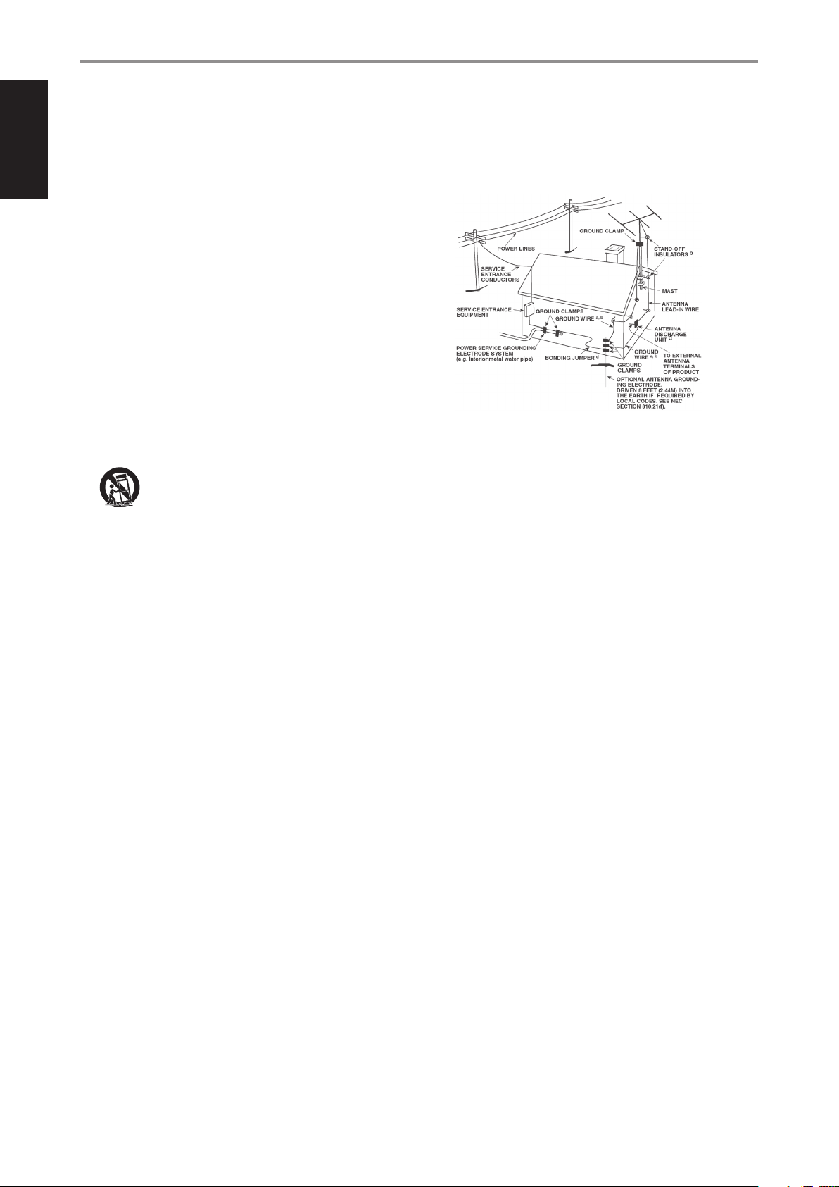
14. Outdoor Antenna Grounding - If an outside antenna or cable system
is connected to the product, be sure the antenna or cable system is
grounded so as to provide some protection against voltage surges
and built-up static charges. Article 810 of the National Electrical Code,
ANSI/NFPA 70, provides information with regard to proper grounding
of the mast and supporting structure, grounding of the lead-in wire
to an antenna discharge unit, size of grounding conductors, location
of antenna discharge unit, connection to grounding electrodes, and
requirements for the grounding electrode.
NOTE TO CATV SYSTEM INSTALLER
This reminder is provided to call the CAT V system installer’s attention to Section 820-40
of the NEC which provides guidelines for proper grounding and, in particular, specifies
that the cable ground shall be connected to the grounding system of the building, as
close to the point of cable entry as practical.
15. Lightning - For added protection for this product during a lightning
storm, or when it is left unattended and unused for long periods of
time, unplug it from the wall outlet and disconnect the antenna or
cable system. This will prevent damage to the product due to lightning
and power-line surges.
16. Power Lines - An outside antenna system should not be located in the
vicinity of overhead power lines or other electric light or power circuits,
or where it can fall into such power lines or circuits. When installing an
outside antenna system, extreme care should be taken to keep from
touching such power lines or circuits as contact with them might be
fatal.
17. Overloading - Do not overload wall outlets, extension cords, or
integral convenience receptacles as this can result in a risk of re or
electric shock.
18. Flame Sources - No naked ame sources, such as lighted candles,
should be placed on the product.
19. Object and Liquid Entry - Never push objects of any kind into this
product through openings as they may touch dangerous voltage
points or short-out parts that could result in a re or electric shock.
Never spill liquid of any kind on the product.
20. Headphones - Excessive sound pressure form earphones and
headphones can cause hearing loss.
21. Damage Requiring Service - Unplug this product from the wall
outlet and refer servicing to qualied service personnel under the
following conditions:
a. When the power-supply cord or plug is damaged.
b. If liquid has been spilled, or objects have fallen into the product.
c. If the product has been exposed to rain or water.
d. If the product does not operate normally by following the
operating instructions. Adjust only those controls that are covered
by the operating instructions as an improper adjustment of other
controls may result in damage and will often require extensive
work by a qualied technician to restore the product to its normal
operation.
e. If the product has been dropped or damaged in any way.
f. When the product exhibits a distinct change in performance-this
indicates a need for service.
22. Replacement Parts - When replacement parts are required, be sure
the service technician has used replacement parts specied by the
manufacturer or have the same characteristics as the original part.
Unauthorized substitutions may result in re, electric shock, or other
hazards.
2
Page 3
IMPORTANT SAFETY INSTRUCTIONS
23. Battery Disposal - When disposing of used batteries, please comply
with governmental regulations or environmental public instruction’s
rules that apply in your country or area.
24. Safety Check - Upon completion of any service or repairs to this
product, ask the service technician to perform safety checks to
determine that the product is in proper operating condition.
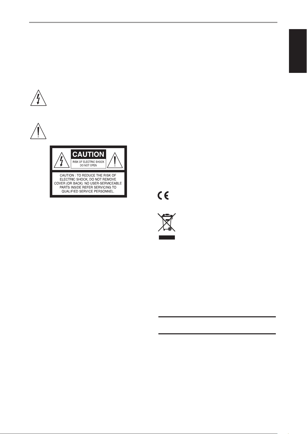
WARNING
The lightning ash with arrowhead symbol, within an
equilateral triangle, is intended to alert the user to the
presence of uninsulated “dangerous voltage” within the
product’s enclosure that may be of sucient magnitude to
constitute a risk of electric shock to persons
The exclamation point within an equilateral triangle is
intended to alert the user to the presence of important
operating and maintenance (servicing) instructions in the
literature accompanying the appliance.
CAUTION
• Changes or modications to this equipment not expressly approved
by NAD Electronics for compliance could void the user’s authority to
operate this equipment.
• To prevent electric shock, match wide blade of plug to wide slot, fully
insert.
• Danger of explosion if battery is incorrectly replaced. Replace only with
the same or equivalent type.
• An appliance with a protective earth terminal should be connected to a
mains outlet with a protective earth connection.
WARNING
• To reduce the risk of re or electric shock, do not expose this apparatus
to rain or moisture.
• The apparatus shall not be exposed to dripping or splashing and
that no objects lled with liquids, such as vases, shall be placed on
apparatus.
• Mains plug is used as disconnect device and it should remain readily
operable during intended use. In order to disconnect the apparatus
from the mains completely, the mains plug should be disconnected
from the mains socket outlet completely.
• Battery shall not be exposed to excessive heat such as sunshine, re or
the like.
IF IN DOUBT CONSULT A COMPETENT ELECTRICIAN.
This product is manufactured to comply with the radio
interference requirements of EEC DIRECTIVE 2004/108/EC.
ENGLISH
THE EQUIPMENT MUST BE CONNECTED TO AN EARTHED MAINS SOCKET-OUTLET.
CAUTION REGARDING PLACEMENT
To maintain proper ventilation, be sure to leave a space around the unit
(from the largest outer dimensions including projections) than is equal to,
or greater than shown below.
Left and Right Panels: 10 cm
Rear Panel: 10 cm
Top Panel: 10 cm
FCC STATEMENT
This equipment has been tested and found to comply with the limits for Class
B digital device, pursuant to Part 15 of the FCC Rules. These limits are designed
to provide reasonable protection against harmful interference in a residential
installation. This equipment generates, uses, and can radiate radio frequency
energy and, if not installed and used in accordance with the instructions, may
cause harmful interference to radio communications. However, there is no
guarantee that interference will not occur in a particular installation. If this
equipment does cause harmful interference to radio or television reception,
which can be determined by turning the equipment o and on, the user is
encouraged to try to correct the interference by one or more of the following
measures:
• Reorient or relocate the receiving antenna.
• Increase the separation between the equipment and receiver.
• Connect the equipment into an outlet on a circuit dierent from that to
which the receiver is connected.
• Consult the dealer or an experienced radio TV technician for help.
NOTES ON ENVIRONMENTAL PROTECTION
At the end of its useful life, this product must not be disposed
of with regular household waste but must be returned to a
collection point for the recycling of electrical and electronic
equipment. The symbol on the product, user’s manual and
packaging point this out.
The materials can be reused in accordance with their markings. Through
re-use, recycling of raw materials, or other forms of recycling of old
products, you are making an important contribution to the protection of
our environment.
Your local administrative oce can advise you of the responsible waste
disposal point.
RECORD YOUR MODEL NUMBER NOW, WHILE YOU CAN SEE IT
The model and serial number of your new M33 are located on the back of
the cabinet. For your future convenience, we suggest that you record these
numbers here:
Model number : . . . . . . . . . . . . . . . . . . . . . . . . . . . . . . . . . . . . . .
Serial number : ......................................
NAD is a trademark of NAD Electronics International, a division of Lenbrook Industries Limited
Copyright 2020, NAD Electronics International, a division of Lenbrook Industries Limited
3
Page 4

INTRODUCTION
TABLE OF CONTENTS
ENGLISH
IMPORTANT SAFETY INSTRUCTIONS .........................2
INTRODUCTION
GETTING STARTED ...............................................5
WHAT’S IN THE BOX ..................................................5
FACTORY RESET ......................................................5
QUICK SETUP GUIDE .................................................6
IDENTIFICATION OF CONTROLS
FRONT PANEL ....................................................7
REAR PANEL .....................................................8
OPERATION
USING THE FRONT PANEL DISPLAY ..............................11
SAMPLE DISPLAY SCREEN .......................................... 11
DIRAC LIVE ......................................................... 16
MASTER QUALITY AUTHENTICATED ................................ 16
MAKING THE MOST OUT OF YOUR M33 ............................ 16
USING THE HTRM 2 REMOTE CONTROL ..........................17
CONTROLLING THE M33 ............................................17
LEARNING CODES FROM OTHER REMOTES ......................... 17
PUNCH THROUGH .................................................. 18
COPY A COMMAND FROM ANOTHER KEY .......................... 18
MACRO COMMANDS ............................................... 18
KEY ILLUMINATION TIMEOUT ....................................... 19
CONFIGURING KEY ILLUMINATION ................................. 19
FACTORY RESET .................................................... 19
LOADING CODELIBRARIES ......................................... 20
SEARCH MODE ..................................................... 20
CHECKING CODE LIBRARY NUMBER ................................ 20
SUMMARY OF THE HTRM 2 MODES ................................ 20
BATTERY INSTALLATION ............................................ 21
REFERENCE
SPECIFICATIONS ................................................22
4
Page 5

INTRODUCTION
GETTING STARTED
WHAT’S IN THE BOX
Packed with your M33 you will nd
• Two detachable mains power cord
• HTRM 2 remote control with 4 AA batteries
• Mic Assembly with Ferrite Base
• USB MIC Sound Adaptor
• USB ash drive
• Four pieces of magnetic feet
• Cleaning cloth
• Quick Setup Guide
NOTE
Follow supplied Quick Setup Guide to help you get started with your
M33.
SAVE THE PACKAGING
Please save the box and the packaging that came with the M33. Should
you move or need to transport your M33, this is the safest container to use.
We’ve seen too many otherwise perfect components damaged in transit
for lack of a proper shipping carton. So please, save that box!
FACTORY RESET
Factory Reset is recommended if your M33 is not functioning or internet
rmware upgrade has failed. All customization including Wi-Fi network
conguration, le shares and saved playlists or settings will be lost. They
have to be re-created once factory reset is completed.
M33 can be factory reset or restored to factory default settings using any of
the following methods.
1 Via Front Panel Display
Go to Settings - Other menu option and select Factory Reset to initiate
restoring of the M33 to factory default settings. Follow the prompt
commands.
2 Force Factory Reset
a Press and hold rear panel RESET tact switch and while doing so, turn
ON the rear panel POWER switch. Do not release hold of the RESET
tact switch.
b Hold down the RESET tact switch - STATUS INDICATOR (NAD logo)
alternately blinks red and white.
c Release the RESET tact switch as soon as the front panel display
shows “Factory Reset…”
d Successful Factory Reset is indicated by the unit rebooting.
- For wireless connection, M33 returns to Hotspot mode and
STATUS INDICATOR (NAD logo) indicator turns into solid white.
- For wired connection, M33 will simply connect as if it was a new
player and NAD logo indicator turns into solid white.
ENGLISH
IMPORTANT
Releasing the Standby button switch at any time before the STATUS
INDICATOR (NAD logo) begins ashing red will cancel the factory reset
and leave the M33 at Upgrade Mode. Just start again the procedure for
Factory Reset.
5
Page 6

ENGLISH
INTRODUCTION
GETTING STARTED
QUICK SETUP GUIDE
This simple guide will help you get started with your M33.
Your M33 can be connected to your home network via Wired or Wireless
connection.
IMPORTANT!
• For wired and wireless connection to be established, ensure that a
broadband router that supports Ethernet and/or Wi-Fi standards is
setup and available.
• Tablets, smartphones and other applicable devices that support iOS
(Apple) or Android operating system can be used as mobile device
controller. These devices are not supplied with your M33.
• Download and install the corresponding “BluOS Controller” App for
your device.
• The BluOS App is available as a Mobile App for Android, iOS, Kindle
and Desktop App for Windows and OS X Computers. Mobile Apps are
handled by the respective Application Store of the Mobile devices.
• Desktop Apps are available to download directly from the Bluesound
homepage - www.bluesound.com
WIRED CONNECTION
Using an Ethernet cable (not supplied), connect one end to M33’s LAN port
and the other end directly to your Wired network or router.
WIRELESS CONNECTION
The process is very easy but slightly diers between iOS (Apple) and
Android devices. Follow below instructions for the smartphone or tablet
that applies to you. Windows and Mac users please see the instructions
underWireless Manual Setupbelow.
NOTE
Ensure that there is no wired connection established.
ANDROID
1 Open App. The App may immediately prompt you saying “New Players
detected”, select ”Setup Now”.
a If you are not prompted, open the Player Drawer by pressing the
Home icon in the top right corner of the App.
b Scroll to the bottom and select”Add a Player”to launch the Easy
Setup Wizard.
c Select your M33’s unique network ID* from the Players detected
Window.
d Select your Home Wi-Fi Network from the“Choose a Wi-Fi Network”
drop down menu.
e If your Home Wi-Fi Network does not appear or is hidden, select
”Manual SSID Entry”. Enter network or applicable wireless network
name.
f Select the“Network Security” your network uses.
iOS
1 Open App. Select Home icon in the top right corner of the App.
2 Scroll to the bottom and select”Add a Player”to launch the Easy Setup
Wizard.
3 As illustrated, press the Home button and open the iOS Settings App to
select the Wi-Fi network you will connect.
4 From the same iOS Settings App, select your M33’s unique network ID*.
Follow prompt instructions.
5 Return to BluOS App upon completion of the network setup
connection.
If the above method does not work or if you are on a Windows PC or Apple
Mac, Wireless Manual Setup can be undertaken.
WIRELESS MANUAL SETUP
1 Select your M33’s unique network ID* from the Wi-Fi Setup connection
settings menu of your tablet, smart phone or computer and join it.
2 “…Control Panel” menu window should automatically open. If not,
open the web browser of your device and visit http://10.1.2.3
3 Select “Congure Wi-Fi” from the “…Control Panel” menu. Select
your network or applicable wireless network name (SSID) from the
“Congure Wireless” drop down menu.
4 Enter your network’s Wireless Password (Passphrase, WEP/WAP key as
applicable) in the eld “Enter password or key (if protected)”.
5 Select a “Player name” from the drop down list or use the on-screen
keyboard to create a customized room name in the eld “Custom
name”.
6 Select “Update” to save all your settings and complete the set up
connection of your M33. Do not forget to go back to the Wi-Fi Settings
section of your device to conrm that it is reconnected to the correct
Wi-Fi network.
Your M33 is now connected to your Wi-Fi network and ready to be used
with the BluOS controller App.
IMPORTANT!
Always ensure that your M33 is updated with the latest rmware. Go
to the M33 product page at nadelectronics.com for rmware update
information.
2 Enter your home network’sWi-Fi Passwordin the eld provided and
select “OK”.
3 Enter the “Player Name” you prefer your M33 to be customized for
easier identication in the Player Drawer. Network setup connection
proceeds automatically.
4 Network setup connection is completed when “All Done!” is shown in
the App.
* The M33’sunique network IDis listed as the product name (i.e. M33)
immediately followed by the last four digits in the MAC (Machine Access
Control) address (example: C658-001A). The full 12-digit MAC address is
printed on a sticker on the M33 rear panel.
6
Page 7
IDENTIFICATION OF CONTROLS
FRONT PANEL
1
ENGLISH
2
© NAD M33
3
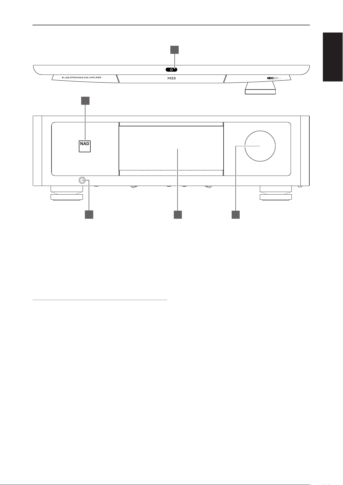
1 o (STANDBY)
• Press o (Standby) button for the M33 to be switched ON from
standby mode. The STATUS INDICATOR (NAD logo) will turn from
amber to white color.
• Pressing o (Standby) button again switches back M33 to standby
mode. The STATUS INDICATOR (NAD logo) will illuminate to amber
color at standby mode.
• The o (Standby) button cannot activate the M33 with the rear
panel POWER switched o.
IMPORTANT NOTES
• Refer also to +12V TRIGGER IN (OFF/AUTO) of IDENTIFICATION OF
CONTROLS - REAR PANEL.
• For the o (Standby) button to activate, two conditions must be
completed.
a Plug-in the supplied mains power cord to mains power source.
Connect corresponding end of the mains power cord to the AC
mains input of M33 and the plug connected to mains power source.
b The rear panel POWER switch must be set to ON position.
2 STATUS INDICATOR (NAD LOGO)
• This indicator will be amber when M33 is in standby mode.
• When M33 is powered up from standby mode, this indicator will
change from amber to solid white.
4 5
4 DISPLAY (TOUCH PANEL DISPLAY)
• Display visual information about current music or media source,
settings or menu options
• Touch control functions are also displayed depending upon menu
option selected.
5 VOLUME
• The VOLUME control adjusts the overall loudness of the signal
driving the speakers or headphones.
• Turn clockwise to increase the volume level; counter clockwise to
lower it.
3 HEADPHONE
• A 1/4” stereo jack socket is supplied for headphone listening and
will work with conventional headphones of any impedance.
• The volume, tone and balance controls are operative for
headphone listening. Use a suitable adapter to connect
headphones with other types of sockets, such as 3.5mm “personal
stereo” jack plugs.
7
Page 8
ENGLISH
© NAD M33
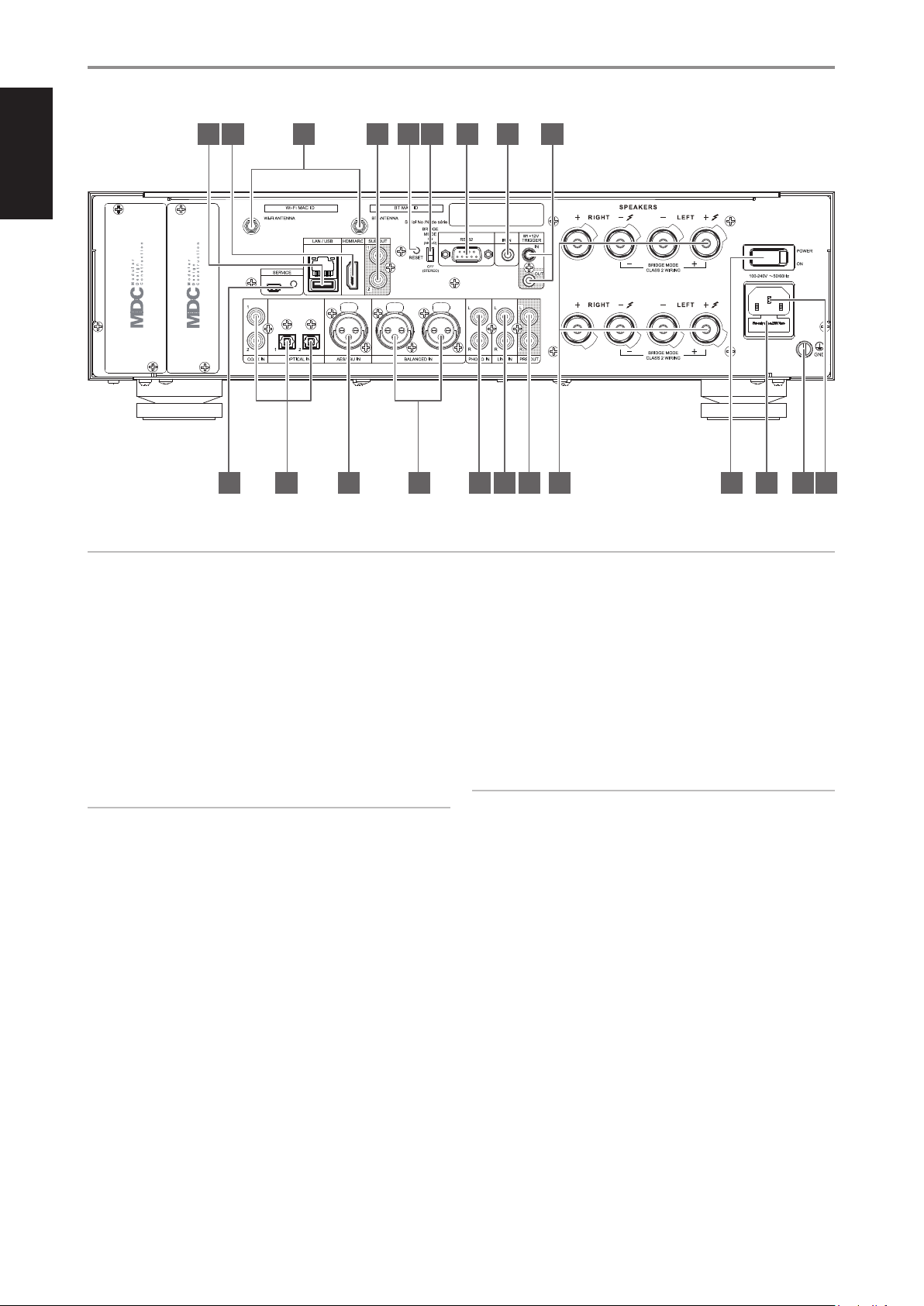
IDENTIFICATION OF CONTROLS
REAR PANEL
1 2 3 4 5 6
7 8 9
10 11 12 2019181716151413
ATTENTION!
Please ensure that the M33 is powered o or unplugged from the mains power outlet before making any connections. It is also advisable to power down or
unplug all associated components while making or breaking any signal or AC power connections.
1 LAN/USB
LAN
• LAN connection must be setup for wired connection to be
established. Set up a Wired Ethernet broadband router with
broadband internet connection. Your router or home network
should have a built-in DHCP server to consummate the connection.
• Using a standard straight-through Ethernet cable (not supplied),
connect one end of the Ethernet cable to the LAN port of your
wired Ethernet broadband router and the other end to M33’s LAN
port.
NOTES
• NAD is not responsible for any malfunction of the M33 and/or the
internet connection due to communication errors or malfunctions
associated with your broadband internet connection or other
connected equipment. Contact your Internet Service Provider (ISP) for
assistance or the service bureau of your other equipment.
• Contact your ISP for policies, charges, content restrictions, service
limitations, bandwidth, repair and other related issues pertinent to
internet connectivity.
USB
• Connect to this USB port USB mass storage devices formatted as
FAT32, NTFS or Linux ext4. The connected USB device appears as a
Local Source (USB) in the BluOS App.
• Access and playback music stored in the connected USB device by
selecting “USB” from the BluOS App.
2 HDMI ARC
• Connect to TV that supports HDMI Control (CEC) and Audio Return
Channel (ARC) functions. Both functions are possible if external
devices that also support both features are interconnected with
M33 via HDMI connection.
• Use HDMI cable to connect HDMI ARC to corresponding HDMI ARC
port of TV.
• With ARC connection established, M33 will output audio signal
from TV.
IMPORTANT
• Ensure that the audio setting/format of ARC- connected devices to M33
is set to PCM only.
• Only audio output signal from TV is supported by HDMI ARC port. There
is no video output at HDMI ARC port of M33.
3 WI-FI AND BLUETOOTH ANTENNA TERMINALS
• Install supplied antennas to corresponding Wi-Fi and BT antenna
terminals.
4 SUB OUT 1, 2
• Connect SUB OUT 1 and/or SUB OUT 2 to the low level input of
corresponding powered subwoofer.
• Low frequency information up to 80 Hz is sent to the connected
subwoofer.
5 RESET
• Use this tact switch in forcing the factory reset of the unit. Refer
to item about FORCING FACTORY RESET under FACTORY RESET
section.
21
8
Page 9

IDENTIFICATION OF CONTROLS
REAR PANEL
6 BRIDGE MODE
The M33 amplier can be congured to be MONO (Bridge Mode),
more than doubling its output power. This way, the M33 can be used
as part of a high power stereo or home-theatre system, by connecting
additional power ampliers.
• In BRIDGED MODE (switch at ON (MONO) setting), the M33 will
produce approximately 640W into an 8 ohm loudspeaker. In this
mode, the amplier sections will react as though the speaker
impedance has been halved. Low impedance speakers (under 8
ohms) are not recommended when using Bridge Mode as these
may cause the amplier’s thermal cut-out to operate if played at
high levels.
• Set the BRIDGE MODE switch to the “ON (MONO)” position and
connect the speaker to the terminals marked “L +” and “R-” ensuring
that the “L+” is connected to the “+” terminal of your speaker and
the “R-” is connected to the speaker’s “ - ” terminal.
• Connect the source to the Left input sockets only. Do not connect
anything to the Right Input socket when Bridge Mode is selected.
7 RS 232
• NAD is an integration partner with several smart control and
automation systems like Control4, Crestron, LUTRON among others.
Check out NAD website for a list of NAD’s integration partners. See
your NAD audio specialist for more information.
• Connect this interface using RS-232 serial cable (not supplied) to
any Windows compatible PC to allow remote control of M33 via
compatible external controllers.
• Refer to NAD website for information about RS232 Protocol
documents and PC interface program.
8 IR IN
• This input is connected to the output of an IR (infrared) repeater
(Xantech or similar) or IR output of another compatible device to
allow control of the M33 from a remote location.
9 +12V TRIGGER IN
• With this input triggered by a 12V DC supply, the M33 can be
switched ON remotely from standby mode by compatible devices
such as ampliers, preampliers, receivers, etc. If the 12V DC supply
is cut o, the M33 will return to standby mode.
• Connect this +12V Trigger input to the remote device’s
corresponding +12V DC output jack using a mono cable with
3.5mm male plug. The controlling device must be equipped with a
+12V trigger output to use this feature.
10 SERVICE
• These USB port and tact switch are for servicing purposes only. Not
for consumer use.
12 AES/EBU IN
• Digital audio stream from professional audio sources can be
connected to this XLR connector. For high-end sources with higher
sampling rates like 176kHz and 192kHz, it is highly recommended
that such sources be interfaced with the AES/EBU IN connector.
The AES/EBU IN is well suited to handle such sources with high
sampling rate.
• The source will appear as “AES/EBU” in the navigation drawer of the
BluOS App.
13 BALANCED IN
• Connect XLR audio source to these connectors. Ensure that proper
pin congurations are followed – Pin 1: Ground, Pin 2: Positive
(signal live) and Pin 3: Negative (signal return).
• The source will appear as “Balanced In” in the navigation drawer of
the BluOS App.
14 PHONO
• Input for either MM or MC phono cartridge. Connect the twin RCA
leads from your turntable to this input.
• If your turntable includes a ground/earth lead, it can be connected
to the Ground Terminal (refer to item 20 below).
• The source will appear as “Phono” in the navigation drawer of the
BluOS App.
15 LINE IN
• Input for line level sources such as CD player, tuner or any
compatible devices. Use dual RCA-to-RCA cable to connect the
source device’s left and right “Audio Output” to these line input
ports.
• The source will appear as “Line In” in the navigation drawer of the
BluOS App.
16 PRE OUT
• Use dual RCA-to-RCA cable to connect PRE-OUT to the
corresponding analog audio input of compatible devices such
as ampliers, receivers or other applicable devices. This makes it
possible to use the M33 as a pre-amplier to such devices.
17 SPEAKERS
• The M33 has two sets of SPEAKER connections which are identical
in function (parallel connection).
• Connect M33’s Right speaker terminals marked “R +” and “R-” to
the corresponding “+” and “-“ terminals of your designated right
speaker. Repeat the same for M33’s Left speaker terminals and
corresponding left speaker.
• Double check the speaker connections before powering up the
M33.
ENGLISH
11 OPTICAL 1-2/COAXIAL 1-2
• Connect to corresponding optical and coaxial digital output of
sources such as CD or BD/DVD players, digital cable box, digital
tuners and other applicable components.
• The sources will appear as “Optical 1”, “Optical 2”, “Coaxial 1” and
“Coaxial 2” in the navigation drawer of the BluOS App.
IMPORTANT NOTES
• The blue terminals must never be connected to ground (earth).
• Never connect the blue terminals together or to any common ground
device.
• Do not connect the output of this amplier to any headphone adapter,
speaker switch or any device that uses common ground for left and
right channels.
9
Page 10

ENGLISH
IDENTIFICATION OF CONTROLS
REAR PANEL
18 POWER
• Supplies the AC mains power to the M33.
• When the POWER switch is set to ON position, the M33 goes to
standby mode as shown by the amber status condition of STATUS
INDICATOR (NAD logo) indicator.
• Press o (Standby) button or HTRM 2’s remote control’s [ON] button
to switch ON the M33 from standby mode.
• If you do not intend to use the M33 for long periods of time (such
as when on vacation), switch o the POWER switch.
• With POWER switched o, neither the front panel Standby button
nor HTRM 2 remote control’s [ON] button can activate the M33.
19 FUSE HOLDER
• Only qualied NAD service technicians can have access to this fuse
holder. Opening this fuse holder may cause damage thus voiding
the warranty of your M33.
20 GROUND TERMINAL
• Ensure that the M33 is plugged-in to a grounded AC wall outlet.
• If necessary, use this ground terminal to connect to ground a
phono or turntable source for PHONO input.
• If a separate earth ground is necessary, use this terminal to ground
your M33. The M33 can be connected to ground by connecting a
ground lead wire or similar to this terminal. After insertion, tighten
the terminal to secure the lead.
21 AC MAINS INPUT
• The M33 comes supplied with two separate mains power cords.
Select the mains power cord appropriate for your region.
• Before connecting the power cord’s plug to the mains power outlet,
ensure that the other end of the power cord is rmly connected to
M33’s AC Mains input socket.
• Always unplug the power cord from the mains power outlet before
disconnecting the other end of the power cord from M33’s AC
Mains input socket.
10
Page 11

OPERATION
USING THE FRONT PANEL DISPLAY
The intuitive front panel display allows the user to perform and navigate
through several functions, features and Sources of M33. Touch anywhere in
the front panel display and below menu options will become available.
NAVIGATING THE FRONT PANEL DISPLAY ITEMS AND MAKING CHANGES
Use your nger to touch, swipe and navigate through the front panel
display items. Touch or swipe (left, right, upwards or downwards) to select
or congure an item.
NOTE
SWIPE – From above display setting, when you swipe your nger from
left to right or vice-versa along the “Source” area of the display, current
Source changes to the next or previous Source.
6 Elapsed playback time of current media
7 Playback controls for applicable media (song, title, le, music station
and others)
0 Skip to next media
4/j Play or pause current media
9 Skip back to previous media
m/, Repeat and random mode controls are also available for
selection
8 Volume level
FRONT VIEW
Now Playing display will switch to selected Front View default screen
if there is no user interaction within 10 seconds. Front View display will
remain until a user interface is made. Front View display can be congured
via Settings-Source Setup-Sources menu.
MENU OPTIONS
Sources
Select preferred Source to access or playback contents
ENGLISH
SAMPLE DISPLAY SCREEN
NOW PLAYING
1
6 7 8
1 New screen is opened showing Sources, Presets and Settings menu
2 Information about album title, song title and artist name
3 Album art cover
4 Source list is displayed where one can select desired Source to access
5 Display “Play Queue” that was setup via the BluOS App. “Play Queue” is
2 3 4 5
options.
Logo or icon for music service provider or media source input (analog,
optical, coaxial, Bluetooth, HDMI ARC, etc.)
or playback contents. Refer also to “SOURCES” item below.
a list of songs or tracks that are populated and put on queue via the
BluOS App.
Presets
Use BluOS App to program into Presets your favourite radio stations, music
streams, playlists or Sources
11
Page 12

ENGLISH
OPERATION
USING THE FRONT PANEL DISPLAY
Settings
Congure or display M33 settings
Player
8 Indicator Brightness: Adjust NAD logo indicator brightness level from
0 to 2
1 Sleep Timer: Stop playback after a set amount of time via gentle
volume decline
2 Room Name: Create a customized room name for the M33 using the
pop up keyboard
3 Tone Controls: Swipe to boost or reduce Bass and Treble response.
Tone Control levels, Bass and Treble, can be turned ON/OFF or Reset.
1
2
3
9 Speaker Output: Turn On or O speaker output
4
10 Bluetooth: Set Bluetooth connection to Manual, Automatic, Guest or
Disable Bluetooth availability
11 LCD Temporary Display: Enabled mode will turn o display
temporarily after 1 minute of non-user interface. Disabled mode will
keep display shown.
8
9
10
11
12
13
4 Balance: Balance control adjusts the relative levels of the left and right
speakers. Swire right to shift the balance to the right or swipe to the left
to shift the balance to the left. “0 dB” level setting provides equal level
to the left and right channels.
5 Select attached speakers: Select corresponding option depending
upon the subwoofer connected - 1 Subwoofer (connect to SUBW OUT
1 only), 2 Subwoofers or No Subwoofer
6 Crossover: The subwoofer will reproduce only low frequency
information below the selected crossover setting.
7 LCD Brightness: Set LCD brightness level from 0% to 100%
12 Volume In Percent: Volume level is displayed in percent when
enabled. At disabled mode, volume level is displayed in dB.
13 LAN/BluOS in Standby: Status of LAN and BluOS activity are indicated
while the unit is at standby mode. LAN and BluOS connections
continue to be active at enabled mode. At disabled mode, LAN and
BluOS connections are idle or inactive
14 Auto Standby: M33 can be setup to automatically go to standby mode
if the current Source has no active audio input for 30 minutes. At enabled
mode, unit will go to standby mode automatically if the current Source
has no active audio input for 30 minutes. At disabled mode, unit remains
active even if the current Source has no active audio input.
14
15
5
6
7
12
Page 13

OPERATION
USING THE FRONT PANEL DISPLAY
15 IR Channel: The M33 has the capability to operate via alternate IR
channel. This is useful if you have two NAD products that can be
operated by similar remote control commands. With alternate IR
Channel, two dierent NAD products can be controlled independently
in the same zone by setting each one to a dierent IR channel.
IR Channel Assignment
The M33 and the HTRM 2 remote control must be set to the same
channel.
To change the Main Zone IR Channel on the M33
• While at “IR Channel” option, select through IR Channel number
options. The default IR Channel is “IR Channel 0”.
To change the IR Channel on the HTRM 2 remote control
• Include a channel number before the library code. For HTRM 2,
library code “100” is the default library table for “AMP” device. To
select this “AMP” library table for “IR Channel 0”, retain the library
code “100”.
• If you want to load the “AMP” library table on “IR Channel 1”, prex
the library code with “1” to indicate association with “IR Channel 1”.
Load then the “AMP” library table using the code “1100”.
Source Setup
Select and congure Source
1 Sources: Select Source to congure
4 Front View: Front display layout and contents can be congured by
selecting the following options
• Album Only, Album and Text, Album, Text and VU, Text Only
• Source (Simple), Source (Detailed)
• Analog VU meter, Digital VU.
A combination of above options is available depending upon the
Source selected.
• Album Only: display album/title art, station ID symbol or icon only
• Album and Text: display album/title art, station ID symbol, icon
and other information like album name, song title, artist name, title
1
of the show, show host, current title of song being played back, etc.
ENGLISH
2 Name: Customize the Source’s Name using the pop-up keyboard
3 Icon: Select and assign icon for the selected Source
2
3
4
5
• Album, Text and VU: display all the information indicated above
for Cover Art and Meta Data plus VU meter*
• Source (Simple): display Source name only which is “BluOS” or
name of Cloud or Radio Service
13
Page 14

ENGLISH
OPERATION
USING THE FRONT PANEL DISPLAY
• Source (Detailed): display Source name plus other information like
volume level.
8 Lip-sync delay: With A/V Mode enabled, “Lip-sync delay” can be
adjusted to ensure your audio is staying in sync over your network
with the original video source. By varying “Lip-sync delay” from 50ms to
150ms, one can delay the audio output to synchronize it with the video
image of the corresponding source.
9 Hide Source: Activate or deactivate selected Source
10 ADC Sample Rate (applies to Analog Sources only)
An analog audio input is converted to digital signal by making use of
M33’s superb circuitry called analog-to-digital converter (ADC).
• Digital VU Meter
• Analog VU Meter
VU Meter monitors or reects audio input level of current BluOS
source. If “Mute” is enabled, the VU meter will not turn o or go to
minimum level as it is the audio output that is muted.
5 Auto Sense (not applicable for Phono and BluOS Sources): At
enabled mode, unit wakes up from standby mode when triggered by
an applicable active Source.
6 MQA Pass-through (applies only to Coaxial and Optical Sources):
Enable MQA Pass-through for the M33 to act as MQA decoder or
renderer when MQA certied CD player or other MQA certied devices
are connected to coaxial or optical input ports.
Using this ADC Rate feature, the sampling rate of the resulting digital audio
signal (available at the digital output ports) can be converted into three
levels - 48K, 96K and 192K. Make sure that the associated equipment will be
able to handle the applicable digital audio signal level.
10
11
11 Analog Gain (applies to Analog Sources only)
Gain adjustment allows all sources to play back at the same volume
level so you don’t need to adjust the volume every time a new source
is selected. It is generally preferable to reduce the level of the loudest
source rather than making louder the softer sources.
12 Phono Type (applies to Phono Sources only)
Select either MM (moving magnet) or MC (moving coil) depending
upon the connected turntable’s phono cartridge.
12
7 A/V Mode: By connecting your TV or other video sources to your
M33 through coaxial, optical or HDMI input ports, you can listen to
your favorite shows or movies through your BluOS system. Grouping
multiple BluOS devices from one of these inputs can require
an abundance of network trac. A/V mode creates a short and
unobtrusive buer to your audio to ensure your BluOS system stays in
sync with your video even with slower or cluttered networks.
Enabled: With A/V Mode enabled on your input source, audio delay
will be automatically adjusted to keep your grouped BluOS devices
in sync with the video source connected. Use the Lip-sync delay
slider below the A/V Mode setting to manually adjust the lower end
of this delay to better suit the speed of your network.
Disabled: When your M33 is connected to an audio source without
video, such as a turntable or CD player, the A/V Mode setting
should be disabled.
14
6
7
8
9
Page 15

OPERATION
USING THE FRONT PANEL DISPLAY
Music Library
1 Reindex Library: Scan for new les added to the Music Library
Other
1 Reboot: Cycle power by powering o and powering back the unit
2 Factory Reset: Restore to factory default settings
3 BluOS Upgrade: Select “BluOS Upgrade” to initiate BluOS upgrade
mode. When “BluOS Upgrade” prompt appears, select “Yes” to start
BluOS upgrade process. Follow the display screen prompt to complete
the upgrade procedure.
System Info
ENGLISH
Display information about the following parameters
• Show current or detected information about BluOS rmware version,
IP Address, MAC Address Ethernet and MAC Address Wi-Fi.
• Temperature Left/Temperature Right: If the internal temperature
of either left or right amplier channel reaches 91 degrees centigrade,
M33 will turn o automatically and a protect message will be shown in
the display. Once the temperature falls below 80 degrees centigrade,
M33 will turn on again and the protect message display will be cleared.
• Temperature Heat Sink Left/Temperature Heat Sink Right/
Temperature MCU/Temperature PSU: Display temperature as
measured over Temperature Heat Sink Left, Temperature Heat Sink
Right, Temperature MCU or Temperature PSU
• Bridge Mode: “On” or “O ” is shown depending upon the setting (ON/
OFF) of the Bridge Mode switch at the rear panel.
15
Page 16

ENGLISH
OPERATION
USING THE FRONT PANEL DISPLAY
DIRAC LIVE
The proprietary Dirac Live is integrated with your M33. Dirac Live® is a
patented room correction technology that not only corrects the frequency
response, but also the impulse response of a room’s loudspeakers. Dirac
Live provides true impulse response correction over a large listening area,
improving the depth, positioning and distinction of individual voices and
instruments. Using multiple measurement and mixed phase correction,
Dirac Live helps create a natural, realistic and transparent sound with
tighter bass and reduced room modes, in a way previously not possible.
Initiate Dirac Live by following below Setup Requirements.
M33
• Update your M33 to the latest rmware.
• Speaker Conguration must match actual speaker setup – turn o
speakers that are not available.
• Both your computer and M33 must be connected to the same network.
MICROPHONE
• The supplied measurement microphone can be connected to either
the MIC or USB input of your computer or the USB input of the M33.
• If the measurement microphone will be connected to the USB
input of your computer or the M33, ensure that the measurement
microphone, phone jack adapter and USB MIC Sound adapter are all
connected together. The USB MIC Sound adapter is not necessary if the
measurement microphone will be connected to the MIC input of your
computer.
• Minimize external noise such as talking, opening/closing of doors or
windows and playback of sound during the measurement.
• Use a microphone stand to rmly place the microphone in the
indicated measurement positions.
MASTER QUALITY AUTHENTICATED
Master Quality Authenticated
(MQA) is a revolutionary end-toend technology built into M33 that
captures and delivers master quality
audio. M33 includes a powerful
decoder and audio renderer for the MQA system. This ensures that MQAencoded audio les sound exactly like the source.
In the BluOS app, the MQA indicator displays green or blue to indicate that
the unit is decoding and playing an MQA le. It displays green to indicate
decoding and playback of a MQA le and denotes provenance to ensure
that the sound is identical to that of the source material. It displays blue to
indicate playback of MQA Studio le that has either been approved in the
studio by the artist/ producer or has been veried by the copyright owner.
Green Indicator - Original MQA file Blue Indicator - MQA Studio file
COMPUTER WINDOWS, macOS
• Both your computer and M33 must be connected to the same network.
• Any active rewalls should allow HTTP (normal WWW access).
• Turn o any computer programs that may make any noise.
• Download Dirac Live App for Windows, macOS and smartphone
(iOS and Android) devices via M33 software download page at
nadelectronics.com/dirac-live.
Launch Dirac Live App. Follow on-screen instructions.
Refer also to the HELP window for more detailed instructions.
View and follow simulated Dirac Live Calibration at:
nadelectronics.com/dirac-live
For further information about Dirac Live Room Correction technology, visit:
www.dirac.com/live-home-professional-audio-info
MQA® is a trademark of MQA Limited.
MAKING THE MOST OUT OF YOUR M33
Download the BluOS Controller App from the respective App stores of
Apple iOS devices (iPad, iPhone and iPod), Android devices, Kindle Fire and
Windows or Mac desktops.
Launch the BluOS Controller App and explore everything from your
streaming music services, internet radio stations, networked music
collections and favorites with quick and easy single-search discovery.
Visit support.bluesound.com for more information about setup and
operation guidelines of your M33.
16
Page 17

USING THE HTRM 2 REMOTE CONTROL
The NAD HTRM 2 is ready to operate the M33 right out of the box, but it is really eight remotes in one.
Each of the 8 Device Selector keys at the top of the handset can call up a new “page” of remote control
codes to be transmitted by the remaining keys. You may “teach” codes from any infrared-remote
controlled component, regardless of brand, to any or all of these.
Obviously, the most logical system is that you teach the codes from your BD player to the [BD] Device
Selector “page,” your television’s codes to the [TV ] “page,” and so on, but there is no required scheme:
You may load any commands to any key on any page (see “Learning Codes From Other Remotes,”
below).
The HTRM 2 is already preprogrammed with a full complement of commands for the M33 on its
[AMP] Device Selector page, and as well as with library commands to operate most NAD-brand CD,
BD or DAC components on the corresponding Device Selector “pages.” These default commands are
permanent: Even if you teach the HTRM 2 new commands to take their place, the underlying library
commands remain in place and can easily be recalled should you add an NAD component to your
system later (see “Delete Mode”, below).
OPERATION
ON
DEVICE SELECTOR
MP
DAC
MMUUTTEE
ENGLISH
OFF
Note: For use with the M33, it should not be necessary to re-program any keys on the HTRM 2 [AMP]
page. However, in order for the HTRM 2 to control your specic NAD-brand components you may
need to load one or more dierent code-libraries (see “Loading Code Libraries,” below).
CONTROLLING THE M33
The HTRM 2 is divided into two main sections. Eight Device Selector keys at the top—[AMP], [MP,]
[TV,] and so on—set the handset’s remaining keys to a “page” of commands to control a particular
component. A Device Select key determines only what component the HTRM 2 will command; it
does not perform any function on the M33. All of the remaining keys are function keys that can “learn”
control codes from virtually any infrared remote controller, allowing you to teach the codes of your
equipment, regardless of brand, to the HTRM 2.
However, the HTRM 2 is already preprogrammed to operate the M33. All of the function keys on the
[AMP] Device Selector “page” perform M33 functions. (The HTRM 2 can also command many other
NAD components, from its [CD], [BD], [DAC] and [CUSTOM] pages.)
It is important to note that certain HTRM 2 keys perform dierent functions depending on the selected
Device Selector “page.”
LEARNING CODES FROM OTHER REMOTES
Begin by positioning the HTRM 2 “nose-to-nose” with the source remote so the two devices’ infrared
windows are about 2 inches apart.
1 Enter Learning Mode: On the HTRM 2, simultaneously press-and-hold for 3 seconds both a Device
Selector key and the [RES] key until the Learn LED (located between HTRM 2’s ON and OFF buttons)
turns steady green.
2 Press the HTRM 2’s function key you wish to teach a command; the Learn LED will turn amber.
3 Press-and-hold the function key on the source remote: The HTRM 2’s Learn LED will icker amber
for a second or two, then turn solid green. The command is learned.
4 Press the HTRM 2’s Device Selector key again to exit the learning mode.
SOURCE
SSLLEEEEPP
IN
8
SSEETTUUPP DDEELLAAYY // PPIICCTTUURREE TTEESSTT // ZZOOOOMM
IN
10
PPRROOGGRRAAMM CCLLEEAARR RREEPPEEAATT
EEQQ TTOONNEE LL..NNIITTEE
DDIIMMMMEERR
CHANNEL VOLUME
HTRM 2
17
Page 18

ENGLISH
OPERATION
USING THE HTRM 2 REMOTE CONTROL
If the Learn LED does not icker amber you may need to vary the distance
between the remotes. If the Learn LED turns red instead of green, the
source remote command could not be learned on that attempt.
Example: Learning “BD Pause”
Position the HTRM 2 and your BD player’s remote as described above.
1 On the HTRM 2, simultaneously press-and-hold [BD] and [RES]; the
Learn LED turns steady green.
2 Press the HTRM 2’s Pause [ j ] key; the Learn LED turns amber.
3 Press-and-hold the corresponding Pause key of your BD player’s remote
control; the HTRM 2’s Learn LED ickers amber and then turns solid
green. The command is learned.
4 Press [BD] again to exit the learning mode.
NOTES
• The DEVICE SELECTOR keys can themselves be congured to learn commands.
• Press and hold a congured DEVICE SELECTOR for at least 2 seconds to
execute a function assigned to the particular DEVICE SELECTOR key.
• A short press of a congured DEVICE SELECTOR will just switch the active
device.
CANCEL OPERATION
You can cancel conguring a key, by pressing the active Device Selector
key before the learn process is complete; the Learn LED will turn red.
PUNCH THROUGH
The HTRM 2’s “punch-through” function allows you to retain a function key
from one Device Select “page” to another, so that, for example, the AMP
[SURR MODE] function might still control the M33 when the BD Device
Selector page is active.
NOTE
The HTRM 2’s [VOL R/T] keys are pre-programmed as “punched-
through” for all Device Selector pages: [VOL R/T] will operate the
M33’s master-volume regardless of the currently selected device. The
[SURR] [CENT] and [SUB] Channel Volume controls similarly are preprogrammed as punched-through.
SET A PUNCH THROUGH
1 Enter Learning Mode and press the desired button to be punched
through.
2 Press twice the Device Selector button of the destination device. The
status LED will turn green.
3 Press the Device Selector button again to exit Learning Mode.
Example: Punch-through AMP [SURR MODE] key to the BD “page”
1 On the HTRM 2, simultaneously press-and-hold [BD] and [RES]; the
Learn LED turns steady green.
2 Press [SURR MODE]; the Learn LED turns amber.
3 Press [AMP] twice; the Learn LED turns green.
4 Press [BD] again to exit the learning mode.
COPY A COMMAND FROM ANOTHER KEY
You may copy a command from any HTRM 2 key to any other key.
COPY A KEY FUNCTION
1 Enter Learning Mode.
2 Press the key that will contain the copied key. The Learn LED turns
steady amber.
3 If the key to be copied resides on another “page”, press rst the
corresponding Device Selector key and then press the desired key to
be copied. The Learn LED turns steady green.
4 Press the Device Selector key again to exit Learning Mode.
Example: Copy the Pause command from the CD page to the AMP [ j ]
button:
1 On the HTRM 2, simultaneously press-and-hold [AMP] and [RES]; the
Learn LED turns steady green.
2 Press Pause [ j ] ; the Learn LED turns amber.
3 Press [CD]; press Pause [ j ] ; the Learn LED turns green.
4 Press [AMP] again to exit the learning mode.
NOTE
The copy and punch-through functions are similar. However, if you
copy a command and then subsequently delete, or over-write the
original (source-key) command , the copied-to key’s command remains
unchanged. If you punch-through to a command and then delete or
over-write the original key, the punched-through functions also change
accordingly.
MACRO COMMANDS
A “macro” command is a series of two or more remote codes issued
automatically from a single keypress. You might use a macro to automate a
simple command sequence, such as, “ Turn on the BD player and then press
PLAY”. Or you might compose an elaborate macro to power up an entire
system, select a source, choose a Listening Mode, and begin playback—
again, all from a single keypress. Each DEVICE SELECTOR and function keys
of the HTRM 2 can be stored one macro.
NOTE
Macros are independent of the currently selected device.
RECORDING MACROS
1 Simultaneously press-and-hold the [MACRO] key and the HTRM 2
function key to be assigned the macro until the status LED turns green.
The macro button will also light up.
2 Press the sequence of function keys to be recorded into the macro.
3 Be sure to press rst the required Device Selector key for each function
(you may switch devices while recording the macro as many times as
necessary), allowing you to create macro containing commands from
more than one Device Selector “page.”
4 After entering the desired command sequence, press [MACRO] again to
store the macro; the Learn LED and [MACRO] key illumination will turn
o.
18
Page 19

OPERATION
USING THE HTRM 2 REMOTE CONTROL
Example: Record a Macro to the [0] key to Turn on the M33.
1 Select “Input 1” (Source 1), and commence playback of connected
Source 1 device (as in BD player).
2 On the HTRM 2, simultaneously press-and-hold [MACRO] and [0]
(numeric zero); the Learn LED turns steady green.
3 Press [AMP]; press [ON]; press [1] (“Input or Source 1”); press [BD]; press
[4] (Play) - the Learn LED blinks as each step is added.
4 Press [MACRO] again to exit the macro-record mode.
To clear a macro, perform the above steps without entering any functions.
NOTE
Each macro can store a maximum of 64 command steps. If you exceed
this number, the macro will be stored automatically after the 64th
command is added.
EXECUTING MACROS
1 Press and release [MACRO]; its key lights for 5 seconds. While it remains
lit, press an HTRM 2 key where a macro has been stored.
2 The corresponding macro will run; as each step executes, its “parent”
Device Selector’s key ashes briey.
3 When nished, the [MACRO] key illumination goes out.
Pressing any other HTRM 2 key while a macro is executing will abort the
macro. Remember that you must hold the HTRM 2 so that its infrared
emitter can activate the target components.
NOTE
When a macro executes, a 1 second delay is automatically inserted
between its commands. If you need more than a 1 second delay
between particular commands—for example, to permit a component
to power up completely—you can record “empty” steps into the macro
by changing Device Selector “pages” without entering actual command
functions.
CONFIGURING KEY ILLUMINATION
Keys to Press (for 3 seconds) Mode
DISP + Digit Key (0-9) Set key illumination timeout to number of
seconds corresponding to digit key. Zero turns o
the key illumination entirely.
DISP + OFF Disable light sensor. Key illumination will turn on
with any key press.
DISP + ON Enable light sensor.
DISP + ENTER Set the light sensor threshold to the current
light level.
DISP + RTN Restore all key illumination settings to the
defaults.
FACTORY RESET
The HTRM 2 can be reset to its factory state, deleting all learned
commands, copied and punched-through keys, macros, and other setup
information, reverting all keys to their pre-programmed library commands.
PERFORM A FACTORY RESET
1 Simultaneously press-and-hold the HTRM 2’s [ON] and [RTN] keys for 10
seconds. The Learn LED will start to ash green.
2 Release [ON] and [RTN] before the second ash is complete; the Learn
LED will turn red, indicating the remote has been reset.
NOTE
Release [ON] and [RTN] before the second ash goes out; otherwise, the
unit will not reset. Should this occur, repeat the full procedure.
DELETE MODE
The HTRM 2 can store learned, copied, and “default library” commands on
any single key. The default library commands are the pre-programmed
NAD codes, such as the native M33 commands on the [AMP] page.
ENGLISH
KEY ILLUMINATION TIMEOUT
The HTRM 2’s key-illumination can be set to remain lit for 0-9 seconds. The
default value is 2 seconds.
SET THE ILLUMINATION TIMEOUT
1 Simultaneously press and hold the HTRM 2’s [DISP] and the [0-9] key
corresponding to the desired timeout duration.
2 The Learn LED will ash twice to conrm the new setting.
3 When set to zero, the illumination will not turn on at all.
NOTES
• Key illumination is activated when one presses any HTRM 2 key.
• If HTRM 2 senses movement, key illumination is activated without
having to press a key. If HTRM 2 is shaken, key illumination is also
activated.
• Key illumination is the biggest drain on the HTRM 2’s batteries. A short
key illumination timeout will extend battery life appreciably; turning it
o altogether (set it to 0 seconds) will lengthen it still further.
You can delete commands by layers back “down” to the default library
command on any key, removing learned commands, punched-through
functions, and copied keys.
NOTE
The default library commands cannot be deleted.
ENTER DELETE MODE
1 Simultaneously press-and-hold the desired key’s Device Selector key
and the [RTN] key for 3 seconds, until the Learn LED turns green.
2 Press the function key whose command you wish to delete; the Learn
LED ashes; the number of times indicates which type of function has
become active - see the table below.
3 Press the active Device Selector key again to exit Delete Mode.
NOTE
You can delete multiple function-key commands on the same Device
Selector “page”. To delete more than one Device Selector page, exit
Delete mode and then re-enter the required page.
Flashes Command Type
1 Default Library Command
2 Copied Library Command
3 Learned Command
19
Page 20

ENGLISH
OPERATION
USING THE HTRM 2 REMOTE CONTROL
LOADING CODE-LIBRARIES
The HTRM 2 can store a dierent library of default NAD codes for each of
its Device Selector “pages.” If the original default library does not control
your NAD CD player, BD player, or other component, follow the procedure
below to change the code-library.
1 Begin by ensuring that the component you wish the HTRM 2 to control
is plugged in and powered-up (“on,” not merely in standby).
2 To enter the HTRM 2s Library Mode, simultaneously press-and-hold
both the desired Device Selector key and the [A/V PSET ] key for 3
seconds, until the Learn LED turns green.
3 While keeping the HTRM 2 pointed toward the component, enter the
rst appropriate three-digit code-library number from the table below.
4 Press [OFF]. If the component turns o, press [ENTER] to accept that
code-library number and exit the Library Mode.
5 If the component does not turn o, enter the next three-digit code-
library number from the table.
6 When you enter the correct number the component will turn o; press
[ENTER] to accept that code library number and exit the Library Mode.
LIBRARY
CODE
100
101
102 S170 302 L70 Tuner
103 L75 303 L53 Tuner
104
3112 Zone 3 305 C425
4112 Zone 4 306 C445
105 L70 307 Txx5 Series Tuner
106 L76 400 Tape Deck B
107 118 401 TAPE Deck A
108 L53 500 TV 280
109 L73 501 MR13
110 Stereo Receiver / Amplier 502 MR20
111 Stereo Second Zone 503 PMR45
112 Txx5 Series 600 T535, T562, T585, M55
200 CD Player 601 T550, L55
201 CD Player (old) 602 T512, T531, T532, T571, T572
202 5170, 5240, 5340 603 L70, L73 BD
203 5325 604 L56
204 5060 605
205 M5 606 L53 BD
NAD PRODUCT
DESCRIPTION
Receiver/Processor
(Discrete ON/OFF)
Receiver/Processor
(Toggle ON/OFF)
Second Zone Commands
(Zone 2)
LIBRARY
CODE
300 Tuner
301 L75, L76 Tuner
304 L73 Tuner
NAD PRODUCT
DESCRIPTION
T513, T514, T515, T517,
T524, T533, T534
SEARCH MODE
If none of the codes from the table work, turn on the component and try
the “search” method as follows:
1 Enter Library Mode by simultaneously pressing-and-holding for 3
seconds the desired Device Selector key and the [A/V PSET ] key, until
the Learn LED turns green.
2 Press-and-hold the HTRM 2’s [R] or [T]) key. The remote will step
through all the available codes at a rate of approximately 1 per second.
3 When the component turns o, release the cursor key.
4 Press [ENTER] to accept that code library and exit Library Mode.
5 Try a few commands. Should you prove to have stepped past the
needed code-library, re-enter the Library Mode and use the cursor key
to step back to it.
NOTE
It is possible that search mode will nd code-libraries that operate, at
least partially, some other brand (non-NAD) components. However, we
can only ensure the completeness or accuracy of NAD code-libraries. We
do not support the HTRM 2’s operation with other-brand components.
CHECKING CODE LIBRARY NUMBER
1 Enter Library Mode by simultaneously pressing-and-holding for 3
seconds the desired Device Selector key and the [A/V PSET ] key, until
the Learn LED turns green.
2 Press the [DISP] key.
3 The HTRM 2 indicates the current code-library by ashing its [DAC],
[CUSTOM], and [MACRO] keys.
For example, to indicate code-library #501, the HTRM 2 will ash [DAC] 5
times, pause, and then ash [MACRO] once. You might wish to make a note
of your components’ code-library numbers.
SUMMARY OF THE HTRM 2 MODES
Mode Keys To Press (for 3 seconds)
Learn/Copy/Punch Through Device Key + RES Key
Delete Mode Device Key + RTN Key
Macro Record Macro Key + Function Key
Library Mode Device Key + [A/V PSET] Key
Back Light Timeout DISP Key + Digit Key
Factory Reset See “Factory Reset” above
20
Page 21

BATTERY INSTALLATION
1 Use the at or rounded end of a pointed tool to push open the pin of
the battery cover.
2 Open the battery hatch.
OPERATION
USING THE HTRM 2 REMOTE CONTROL
ENGLISH
3 Insert the supplied four AA batteries.
4 Push the battery hatch until it clicks close.
5 Restore the battery cover.
21
Page 22

ENGLISH
REFERENCE
SPECIFICATIONS
All specs are measured according to IHF 202 CEA 490-AR-2008 standard. THD is measured using AP AUX 0025 passive lter and AES 17 active lter.
AMPLIFIER SECTION
LINE IN, SPEAKER OUT
Rated output power (ref. 20 Hz-20 kHz at
rated THD, both channels driven)
Rated output power, Bridge mode
(ref. 20 Hz – 20 kHz at rated THD)
Input sensitivity
THD (20 Hz – 20 kHz) <0.003 % (1W to 200 W, 8 ohms and 4 ohms)
Signal-to-Noise ratio >98 dB (A-weighted, ref. 1 W out in 8 ohms)
Clipping power >210 W (0.1 % THD 1 kHz 8 ohms)
IHF dynamic power 8 ohms: 260 W
Peak output current ≥25 A (in 1 ohm, 1 ms)
Damping factor >800 (ref. 8 ohms, 20 Hz to 6.5 kHz)
Frequency response ±0.2 dB (20 Hz -20 kHz)
PREAMPLIFIER SECTION
LINE IN
Input impedance (R and C) 47 kohms/180 pF
Input sensitivity 280 mV (ref. 500 mV out, Volume maximum)
Maximum input level 2 Vrms/8 Vrms (low sensitivity mode)
Tone controls Treble: ±10 dB at 10 kHz
PREOUT
Maximum output level 3.9 Vrms (ref. 0.1% THD)
Signal-to-Noise ratio >120 dB (A-weighted, ref. 2 V out)
Output impedance 100 ohms
SUBOUT
Maximum output level 1.1 Vrms (ref. 0.1 % THD 100Hz)
Signal-to-Noise ratio >102 dB (20 Hz-20 kHz, ref. 1V out)
THD+N <0.005 % (refer 1.1 V 20 Hz-200 Hz)
Output impedance 680 ohms
PHONO
Input sensitivity MM: 1.2 mV
Input impedance (R and C) MM: 56 kohms/100 pF
Signal to noise ratio
(ref. 2 V Preout A-weighted)
THD+N (ref 2V Preout 1kHz) MM: <0.003 %
RIAA response accuracy MM/MC ±0.2 dB 20 H z -20 kHz
HEADPHONE
Output impedance 2.2 ohms
Output power >100 mW/32 ohms
>200 W into 8 ohms
>380 W into 4 ohms
>700 W into 8 ohms
865 mV (ref. 200W 8 ohms, Volume maximum)
>120 dB (A-weighted, ref. 200 W out in
8 ohms)
4 ohms: 520 W
-3 dB at 60 kHz
Bass: ±10dB at 100 Hz
MC: 100 µV
MC: 100 ohms/280 pF
MM: >92 dB
MC: >76 dB
MC: <0.02 %
BluOS SECTION
AUDIO
Supported audio le format* MP3, AAC, WMA, OGG, WMA-L, ALAC, OPUS
Supported high- resolution audio le
format*
Sampling rate up to 192 kHz
Bit depths 16 – 24
CONNECTIVITY
Network connectivity Gigabit Ethernet RJ45
Supported network le share protocol Ser ver Message Block (SMB)
USB 1 x Type-A port for connection to USB
Bluetooth quality aptX HD 5.0
Bluetooth connectivity Two-Way (Receive and Headphone modes)
USER INTERFACE
Supported operating system** Music playback from network shares on
Mobile Application Free BluOS Controller App available for
Front panel 7-inch full colour touch screen
Remote control HTRM 2 remote control
SUPPORTED SERVICES
Streaming cloud services* Spotify, Amazon Music, WiMP, Qobuz,
Free internet radio* TuneIn, iHeartRadio, Calm Radio, Radio
Integration partners*** Control4, RTI, Crestron, URC, push, iPor t,
Voice Control Integration*** Skills and support for Amazon Alexa,
POWER CONSUMPTION
Standby power <0.5W (Auto standby ON)
DIMENSION AND WEIGHT
Gross dimensions (W x H x D)**** 435 x 133 x 396 mm
Shipping weight 18.4 kg (40.6 lbs)
FLAC, MQA, WAV, AIFF
Wi-Fi 5
memory stick (FAT32 or NTFS formatted)
and supported peripherals
the following desktop operating systems:
Microsoft Windows XP, 2000, Vista, 7, 8 to
current Windows Operating Systems and
macOS versions**
download from the respective App stores
of Apple iOS devices (iPad, iPhone and
iPod), Android devices, Kindle Fire and
Windows or macOS desktops
IDAGIO, Deezer, Mure, nugs.net, TIDAL,
Napster, Bugs, KKBOX, Taihe Music ZONE,
SOUNDMACHINE, RADIO.COM
Paradise, LiveXLive
ELAN, Lutron, Roon, AirPlay 2
Google Assistant and Apple’s Siri with
corresponding enabled devices and App
<40W (idle power)
17 ⁄ x 5 ¼ x 15 ⁄ inches
* - Supported audio file format, cloud services and free internet radio are subject to change without notice.
** - Compatibility to latest versions is subject to future software update.
*** - Some features will be available via future software update.
**** - Gross dimension includes feet and extended rear panel terminals
Specifications are subject to change without notice. Check out www.NADelectronics.com for updated documentation or latest information about M33.
22
Page 23

ENGLISH
23
Page 24

ENGLISH
24
Page 25

ENGLISH
25
Page 26

www.NADelectronics.com
©2020 NAD ELECTRONICS INTERNATIONAL
A DIVISION OF LENBROOK INDUSTRIES LIMITED
All rights reserved. NAD and the NAD logo are trademarks of NAD Electronics International, a division of Lenbrook Industries Limited.
No part of this publication may be reproduced, stored or transmitted in any form without the written permission of NAD Electronics International.
While every effort has been made to ensure the contents are accurate at the time of publication, features and specifications may be subject to change without prior notice.
M33OMENV07 JUL 2020
 Loading...