

Page 1
®
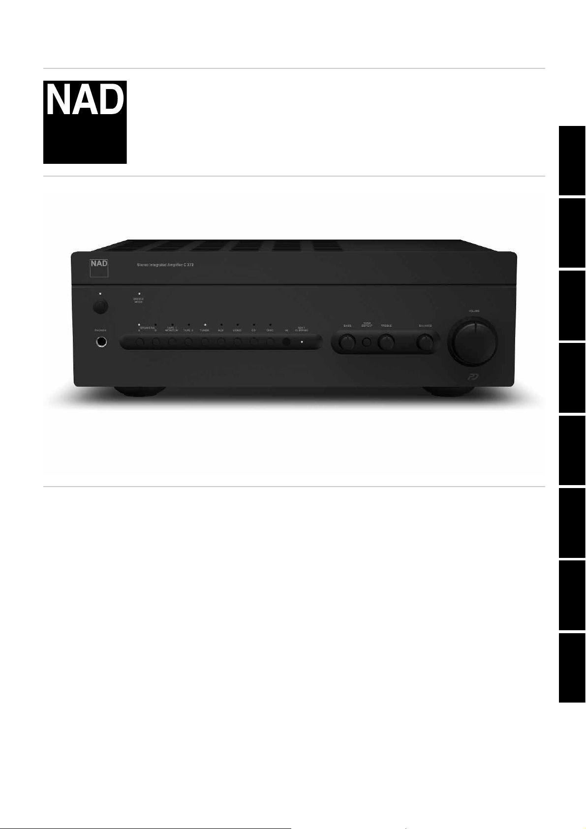
C 372
Stereo Integrated Amplifier
ENGLISH
FRANÇAISDEUTSCH
Owner’s Manual
Manuel d’Installation
Bedienungsanleitung
Gebruikershandleiding
Manual del Usuario
Manuale delle Istruzioni
Manual do Proprietário
Bruksanvisning
NEDERLANDS
ESPAÑOLITALIANO
PORTUGUÊS
SVENSKA
Page 2
IMPORTANT SAFETY INSTRUCTIONS
CAUTION
RISK OF ELECTRIC
SHOCK DO NOT OPEN
ATTENTION:
RISQUE DE CHOC ELECTRIQUE
NE PAS OUVRIR
CAUTION: TO REDUCE THE RISK OF ELECTRIC
SHOCK, DO NOT REMOVE COVER (OR BACK). NO
USER SERVICEABLE PARTS INSIDE. REFER SERVICING
TO QUALIFIED SERVICE PERSONNEL.
Warning: To reduce the risk of fire or electric shock, do not
expose this unit to rain or moisture.
The lightning flash with an arrowhead symbol within an equilateral
triangle, is intended to alert the user to the presence of uninsulated
“dangerous voltage” within the product’s enclosure that may be of
sufficient magnitude to constitute a risk of electric shock to persons.
The exclamation point within an equilateral triangle is intended to
alert the user to the presence of important operating and
maintenance (servicing) instructions in the literature accompanying
the product.
Do not place this unit on an unstable cart, stand or tripod, bracket
or table. The unit may fall, causing serious injury to a child or adult
and serious damage to the unit. Use only with a cart, stand, tripod,
bracket or table recommended by the manufacturer or sold with
the unit. Any mounting of the device on a wall or ceiling should
follow the manufacturer’s instructions and should use a mounting
accessory recommended by the manufacturer.
An appliance and cart combination should be moved with care.
Quick stops, excessive force and uneven surfaces may cause the
appliance and cart combination to overturn.
Read and follow all the safety and operating instructions before
connecting or using this unit. Retain this notice and the owner’s
manual for future reference.
All warnings on the unit and in its operating instructions should be
adhered to.
Do not use this unit near water; for example, near a bath tub,
washbowl, kitchen sink, laundry tub, in a wet basement or near a
swimming pool.
The unit should be installed so that its location or position does not
interfere with its proper ventilation. For example, it should not be
situated on a bed, sofa, rug or similar surface that may block the
ventilation openings; or placed in a built-in installation, such as a
bookcase or cabinet, that may impede the flow of air through its
ventilation openings.
The unit should be situated from heat sources such as radiators,
heat registers, stoves or other devices (including amplifiers) that
produce heat.
The unit should be connected to a power supply outlet only of the
voltage and frequency marked on its rear panel.
The power supply cord should be routed so that it is not likely to be
walked on or pinched, especially near the plug, convenience
receptacles, or where the cord exits from the unit.
Unplug the unit from the wall outlet before cleaning. Never use
benzine, thinner or other solvents for cleaning. Use only a soft
damp cloth.
The power supply cord of the unit should be unplugged from the
wall outlet when it is to be unused for a long period of time.
Care should be taken so that objects do not fall, and liquids are not
spilled into the enclosure through any openings.
This unit should be serviced by qualified service personnel when:
A. The power cord or the plug has been damaged; or
B. Objects have fallen, or liquid has been spilled into the unit; or
C. The unit has been exposed to rain or liquids of any kind; or
D. The unit does not appear to operate normally or exhibits a
marked change in performance; or
E. The device has been dropped or the enclosure damaged.
POUR ÉVITER LES CHOC ELECTRIQUES, INTRODUIRE LA
LAME LA PLUS LARGE DE LA FICHE DANS LA BORNE
CORRESPONDANTE DE LA PRISE ET POUSSER JUSQU’AU
FOND.
TO PREVENT ELECTRIC SHOCK, MATCH WIDE BLADE OF
PLUG TO WIDE SLOT FULLY INSERT.
If an indoor antenna is used (either built into the set or installed
separately), never allow any part of the antenna to touch the metal
parts of other electrical appliances such as a lamp, TV set etc.
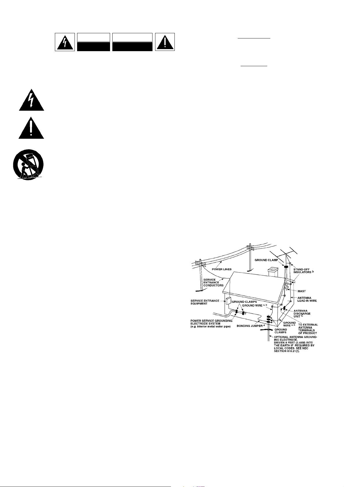
Any outdoor antenna must be located away from all power lines.
If an outside antenna is connected to your tuner or tunerpreamplifier, be sure the antenna system is grounded so as to
provide some protection against voltage surges and built-up static
charges. Article 810 of the National Electrical Code, ANSI/NFPA No.
70-1984, provides information with respect to proper grounding of
the mast and supporting structure, grounding of the lead-in wire to
an antenna discharge unit, size of grounding conductors, location of
antenna discharge unit, connection to grounding electrodes and
requirements for the grounding electrode.
a. Use No. 10 AWG (5.3mm2) copper, No. 8 AWG (8.4mm2)
b. Secure antenna lead-in and ground wires to house with stand-off
c. Mount antenna discharge unit as close as possible to where lead-
d. Use jumper wire not smaller than No.6 AWG (13.3mm2) copper,
EXAMPLE OF ANTENNA GROUNDING AS PER NATIONAL ELECTRICAL
CODE INSTRUCTIONS CONTAINED IN ARTICLE 810 - RADIO AND
TELEVISION EQUIPMENT.
NOTE TO CATV SYSTEM INSTALLER: This reminder is provided to
call the CATV system installer’s attention to Article 820-40 of the
National Electrical Code that provides guidelines for proper
grounding and, in particular, specifies that the ground cable ground
shall be connected to the grounding system of the building, as close
to the point of cable entry as practical.
OUTDOOR ANTENNA GROUNDING
aluminium, No. 17 AWG (1.0mm2) copper-clad steel or bronze
wire, or larger, as a ground wire.
insulators spaced from 4-6 feet (1.22 - 1.83 m) apart.
in enters house.
or the equivalent, when a separate antenna-grounding electrode
is used. see NEC Section 810-21 (j).
ATTENTION
CAUTION
CAUTION
POWER LINES
DO NOT ATTEMPT SERVICING OF THIS UNIT
YOURSELF. REFER SERVICING TO QUALIFIED
Upon completion of any servicing or repairs, request the service
shop’s assurance that only Factory Authorized Replacement Parts
with the same characteristics as the original parts have been used,
and that the routine safety checks have been performed to
guarantee that the equipment is in safe operating condition.
REPLACEMENT WITH UNAUTHORIZED PARTS MAY RESULT IN FIRE,
ELECTRIC SHOCK OR OTHER HAZARDS.
SERVICE PERSONNEL
2
Page 3
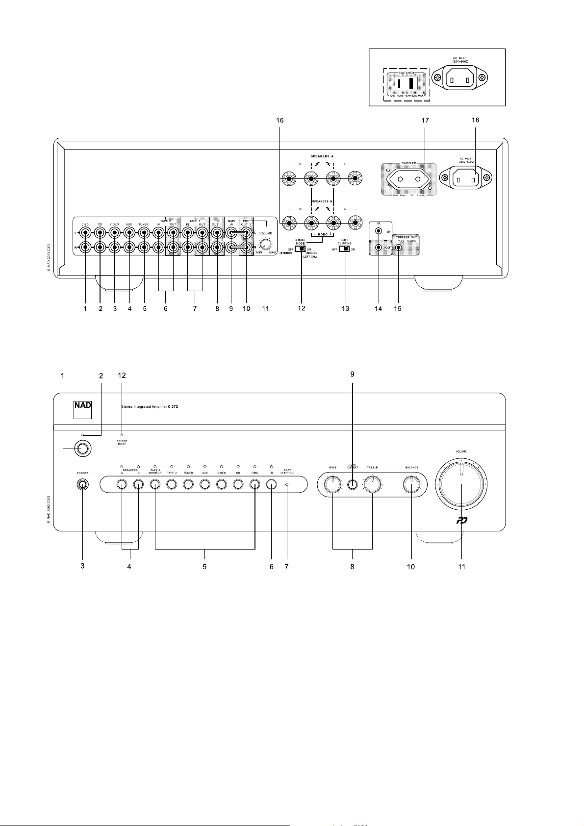
REAR PANEL CONNECTIONS
FRONT PANEL CONTROLS
North American
3
Page 4

ENGLISH FRANÇAIS
QUICK START
1 Connect the speakers to the Speaker A terminals and sources to the
relevant rear input sockets.
2 Plug in the AC power cord.
3 Press the POWER button to turn the NAD C 372 on.
4 Press the required input selector.
NOTES ON INSTALLATION
Your NAD C 372 should be placed on a firm, level surface. Avoid placing
the unit in direct sunlight or near sources of heat and dampness. Allow
adequate ventilation. Do not place the unit on a soft surface like a
carpet. Do not place unit in an enclosed position, such a bookcase or
cabinet, that may impede the air-flow through the ventilation slots.
Make sure the unit is switched off before making any connections.
6. TAPE 2 IN, OUT
Connections for analogue recording and playback to an audio tape
recorder of any type. Using twin RCA-to-RCA leads, connect to the left
and right 'Audio Output' of the tape machine to the TAPE 2 IN sockets
for playback. Connect the left and right 'Audio Input' of the tape
machine to the TAPE 2 OUT sockets for recording.
7. TAPE 1 IN, OUT
Connections for analogue recording and playback to a secondary audio
tape recorder of any type. Using twin RCA-to-RCA leads, connect to the
left and right 'Audio Output' of the tape machine to the TAPE 1 IN
sockets for playback and tape monitoring. Connect the left and right
'Audio Input' of the tape machine to the TAPE 1 OUT sockets for
recording.
DEUTSCH
ESPAÑOL
ITALIANO
PORTUGUÊS
SVENSKA
The RCA sockets on your NAD C 372 are colour coded for convenience.
Red and white are Right and Left audio respectively, and yellow for NAD
Link. Use high quality leads and sockets for optimum performance and
reliability. Ensure that leads and sockets are not damaged in any way
and all sockets are firmly pushed in.
For best performance, use quality speaker leads of 16 gauge (1.5mm)
thickness or more. If the unit is not going to be used for some time,
disconnect the plug from the AC socket.
Should water get into your NAD C 372, shut off the power to the unit
and remove the plug from the AC socket. Have the unit inspected by a
qualified service technician before attempting to use it again. Do not
remove the cover, there are no user-serviceable parts inside. Use
a dry soft cloth to clean the unit. If necessary, lightly dampen the cloth
with soapy water. Do not use solutions containing benzol or other
volatile agents.
REAR PANEL CONNECTIONS (FIGURE 1)
1. DISC INPUT
Input for additional line level input signals such as CD, Mini Disc player
or the output signal from a step-up amplifier for a turntable. Use a twin
RCA-to-RCA lead to connect the auxiliary unit's left and right 'Audio
Outputs' to this input.
2. CD INPUT
Input for a CD or other line-level signal source. Use a twin RCA-to-RCA
lead to connect the CD player's left and right 'Audio Outputs' to this
input. The NAD C 372 only accepts analogue signals from your CD
player.
3. VIDEO INPUT
Input for the audio signal from a stereo VCR (or stereo TV/Satellite/Cable
receiver) or other line-level audio source. Using twin RCA-to-RCA leads,
connect to the left and right 'Audio Out' of the unit to these inputs.
Note: These are audio inputs only.
8. PRE OUT 1
In normal use the PRE OUT 1 is connected to the Main-In sockets
(No. 9) with the links supplied. The NAD C 372 allows for the
connection of multiple power amplifiers. If you are using a single,
external stereo power amplifier, disconnect the links to the Main-In
sockets. The C 372's internal power amplifier is now disconnected.
Use a twin RCA-to-RCA lead to connect to the left and right 'Audio
Input' of the Power amp to the PRE OUT 1 sockets.
NOTES: Always turn the C 372 and associated external power
amplifiers off before connecting or disconnecting anything to the PREOUT 1, 2 and MAIN-IN sockets. The PRE-OUT 1&2 output signals will be
affected by the NAD C 372's volume and tone control settings.
9. MAIN IN
Connections to an external pre-amplifier or processor, such as a
surround-sound decoder. In normal use these are connected to the PreOut 1 sockets (No. 8) with the links supplied. To connect your NAD
C 372 to external processor or pre-amplifier first remove these links. Use
a twin RCA-to-RCA lead to connect to the left and right 'Audio Output'
of the pre-amp or processor to the Main-In sockets.
NOTES: Always turn the C 372 and associated external power
amplifiers off before connecting or disconnecting anything to the PREOUT 1, 2 and MAIN-IN sockets.
The PRE-OUT 1&2 output signals will be affected by the NAD C 372's
volume and tone control settings.
10. PRE OUT 2
The PRE OUT 2 sockets can be used to drive an additional power
amplifier. The VOLUME Pre-Out 2 control (No. 11) can be used to reduce
the output level of the pre-amplifier to the power amplifier by up to 12dB. With the VOLUME Pre-Out 2 control set to the maximum position
(at the 0dB position), the output level will be identical to that of the PRE
OUT 1 sockets.
4. AUX INPUT
Input for additional line level input signals such as another CD player.
Use a twin RCA-to-RCA lead to connect the auxiliary unit's left and right
'Audio Outputs' to this input.
5. TUNER INPUT
Input for a Tuner or other line-level signal source. Use a twin RCA-to-RCA
lead to connect the Tuner left and right 'Audio Outputs' to this input.
4
Page 5

If you are using a pair of power amplifiers specifically for Bi-Amping,
use the PRE OUT 2 sockets to connect the power amplifier with the
highest gain of the pair. By adjusting the VOLUME PRE OUT 2 control
(No. 11) the volume level can be matched exactly to that of the power
amplifier connected to the PRE OUT 1 sockets. Refer also to chapter
"Bi-Amping" for more information. Use a twin RCA-to-RCA lead to
connect to the left and right 'Audio Input' of the Power amp to the PRE
OUT 1 & 2 sockets.
NOTES: Always turn the C 372 and associated external power
amplifiers off before connecting or disconnecting anything to the PREOUT 1, 2 and MAIN-IN sockets.
The PRE-OUT 1&2 output signals will be affected by the NAD C 372's
volume and tone control settings.
11. VOLUME PRE OUT 2
The VOLUME Pre-Out 2 control allows for adjustment of the output
level of the PRE OUT 2 sockets. The output level can be reduced from
0dB to -12dB; when set to the maximum position (at the 0dB position),
the output level will be identical to that of the PRE OUT 1 sockets. Refer
also to chapter "Bi-Amping" for more information.
NOTES: Always turn the C 372 and associated external power
amplifiers off before connecting or disconnecting anything to the PREOUT 1, 2 and MAIN-IN sockets.
The PRE-OUT 1&2 output signals will be affected by the NAD C 372's
volume and tone control settings.
12. BRIDGE MODE
The NAD C 372 can be used as part of a higher power stereo or hometheatre system, by connecting adding additional power amplifiers. If the
power amp section in the NAD C 372 is to be used to drive a single
speaker, then use the Bridge switch to run the built-in Left and Right
power amplifiers as a single channel, high power unit. Set the BRIDGE
MODE switch to the 'Bridge' position and connect the speaker to the
terminals marked 'L +' and 'R+' ensuring that the 'L+' is connected to the
'+' terminal on your loudspeaker and the 'R+' is connected to the
loudspeaker's '-' terminal. Connect the source to the Left MAIN-IN input.
If your listening involves moderate power levels you may leave the Soft
Clipping™ switch to Off. If you are likely to play at high levels, that could
stretch the amplifier's power capability, then switch Soft Clipping On.
The Soft Clipping™ indicator on the front panel will illuminate when the
amplifier is in Soft Clipping mode.
14. IR IN, OUT
The IR IN/OUT connector is used to pass commands from other units
fitted with IR IN/OUT connectors. This allows centralized control of a
complete system, and also allows some of the basic functions of other
NAD components (such as a tuner, CD player or cassette-deck) also
equipped with IR IN/OUT to be controlled with the amplifier's remote
control. To function with such other units, connect the C 372's IR OUT
to the IR IN on the other unit. The IR connectors can be daisy-chained,
IN to OUT, so that a whole system can be controlled from the remote
control facilities of one unit.
NOTES: It is advisable not to connect IR IN/OUT if these units that have
their own built-in remote control command receiver and are positioned
together, in direct view from the remote control handset. If you are
unsure, try operating the products without IR IN/OUT first; If the unit
responds to the remote control command, it will not be necessary to
connect IR IN/OUT. Never loop the last unit back to the first NAD unit in
the IR IN/OUT chain. Unplug all units from the mains before connecting
or disconnecting IR IN/OUT.
15. 12V TRIGGER OUT
This output allows to remotely switch on or off ancillary equipment such
as a tuner, power amplifier, etc. which are also equipped with a 12V
trigger input. This can also be an AC outlet power strip equipped with
a 12V trigger input. The 12V trigger output is activated whenever the
unit is switched to normal operational mode from Stand-by or Off.
For switching Stand-by/Power On of an external component through
the C 372, connect the12V-trigger output of the C 372 to the remote
component's DC input jack. The plug required is a standard 3.5mm
Mini-Jack plug ("mono"): The tip is the live or + connection, the shaft
of the input jack is the 12V-trigger - or ground connection.
ENGLISH
FRANÇAISDEUTSCHESPAÑOLITALIANO
In Bridged Mode the NAD C 372 will produce approximately 300W into
an 8 ohm loudspeaker. In this mode, the amplifier sections will react as
though the speaker impedance has been halved. Low impedance
speakers (under 8 ohms) are not recommended when using Bridge
Mode, as these may cause the amplifier's thermal cut-out to operate if
played at high levels.
The Bridge LED on the front panel (Fig. 2; No. 2) will illuminate when
the amplifier is in Bridge mode.
NOTES: Do not connect anything to the Right MAIN-IN input (No. 9)
when Bridge Mode is selected. Always turn the C 372 and associated
external power amplifiers off before connecting or disconnecting
anything to the PRE-OUT 1, 2 and MAIN-IN sockets.
13. SOFT CLIPPING™
When an amplifier is driven beyond its specified power output, a hard,
distorted sound can be heard on very loud sounds. This is caused by the
amplifier cutting off or 'hard clipping' the peaks of sound that it was not
designed to reproduce. The NAD Soft Clipping™ circuit gently limits the
output of the system to minimise audible distortion if the amplifier is
overdriven.
NOTES: Check the specifications of the Trigger input terminal on the
other components to ensure these are compatible with the C 372's 12Vtrigger output. NAD components equipped with 12V input triggers are
fully compatible with the C 372's 12V output trigger. The C 372's 12Vtrigger output voltage is 12V DC. The total maximum current must not
exceed 200mA. Typically, NAD 12V input triggers draw less than 10mA
of current.
Before making any connections to any 12V trigger input or output,
make sure all components are disconnected from the AC mains.
Failure to observe the above may result in damage to the C 372 or any
ancillary components attached to it. If in doubt over the connections,
installation and operation of the 12V trigger output consult your NAD
dealer.
16. SPEAKERS A + SPEAKERS B
The NAD C 372 is equipped with two sets of speaker connectors. Use
the Speakers A connectors for the 'main' speakers and use the Speakers
B connectors for a second pair, for example, extension speakers located
in another room.
PORTUGUÊS
SVENSKA
5
Page 6
ENGLISH FRANÇAIS
DEUTSCH
ESPAÑOL
ITALIANO
Under normal operation, connect the right speaker to the terminals
market 'R +' and 'R-' ensuring that the 'R+' is connected to the '+'
terminal on your loudspeaker and the 'R-' is connected to the
loudspeaker's '-' terminal. Connect the terminals marked 'L+' and 'L-'
to the left speaker in the same way.
In Bridge Mode, connect the single speaker to the terminals marked 'R
+' and 'L+' ensuring that the 'L+' is connected to the '+' terminal on
your loudspeaker and the 'L+' is connected to the loudspeaker's '-'
terminal. Refer also to section "Bridging" in this chapter (No. 12).
Always use heavy duty (16 gauge; 1.5mm, or thicker) stranded wire
to connect loudspeakers to your NAD C 372. The high-current
binding post terminals can be used as a screw terminal for cables
terminating in spade or pin sockets or for cables with bare wire ends.
BARE WIRES AND PIN CONNECTORS
Bare wires and pin sockets should be inserted into the hole in the shaft
of the terminal. Unscrew the speaker terminal's plastic bushing until the
hole in the screw shaft is revealed. Insert the pin or bare cable end into
the hole and secure the cable by tightening down the terminal's
bushing. Ensure bare wire from the speaker cables does not touch the
back panel or another socket . Ensure that there is only 1/2" (1cm) of
bare cable or pin and no loose strands of speakers wire.
NOTE: Make sure the speaker impedance is 4 ohms or more when
connecting only one pair of speakers; make sure the speaker impedance
for all speakers is more then 8 ohms when connecting two sets of
speakers. In Bridge Mode, the impedance of the loudspeaker should
also be 8 ohms or higher.
17. SWITCHED AC OUTLET
The AC power cord of another component may be plugged into this
accessory outlet. Components plugged into this outlet will be switched
On and Off by the POWER button on the front panel or by the ON and
STAND-BY button on the remote control handset.
REMOTE CONTROL (FIGURE 3) ON AND OFF BUTTONS
Press the POWER button to switch the amplifier On. The Stand-by
indicator (No. 2) over the power button will light up amber. Pressing the
POWER switch again will turn the unit OFF completely, it will not
respond to the remote control. The NAD C 372 remote has a separate
On and Off button. This can be particularly useful to keep components
within a system "in sync": This way all components will switch to standby when Off is pressed or switch to operating mode when On is pressed,
instead of some components switching On when the amplifier is
switched to Stand-by. (Note that the other components have to be
capable of responding to the separate On and Off commands as well).
Press the ON button to switch the unit from Stand-by to the operating
mode; The Stand-by indicator (Fig. 2; No. 2) will turn from amber to red,
then to green and the indicator for the last selected input will blink and
light up. Press the OFF button to switch the unit to the Stand-by mode:
The Stand-by indicator will light up amber.
NOTE: In Stand-by mode the C 372 uses very little power. However, it
is recommended that you switch the unit totally off if it is not going to
be used for more than a couple of days. Switch off completely by
pressing the POWER button on the front panel (No. 1), all lights will
extinguish.
2. POWER / STAND-BY / PROTECTION INDICATOR
Upon switching the power on, the LED will light up amber in standby
state. While one of the input select buttons is pressed, the LED will turn
red for a moment, then turn green for ON state. In cases of serious
abuse of the amplifier, such as overheating, excessively low loudspeaker
impedance, short circuit etc. the amplifier will engage its Protection
circuitry, indicated by the LED turning from green to red, and the sound
being muted. In such a case, turn the amplifier off, wait for it to cool
down and/or check the speaker connections, making sure the overall
loudspeaker impedance doesn’t go below 4 ohms. Once the cause for
the protection circuitry to engage has been removed, press Power again
to resume normal operation.
PORTUGUÊS
SVENSKA
NOTE: The total power consumption of any components connected to
the AC outlets may not exceed 100 Watts.
18. IEC AC MAINS (POWER) INPUT
The C 372 comes supplied with a separate AC Mains cable. Before
connecting the cable to a live wall socket ensure that it is firmly
connected to the NAD C 372's AC Mains input socket first. Always
disconnect the AC Mains cable plug from the live wall socket first,
before disconnecting the cable from the C 372 Mains input socket.
FRONT PANEL CONTROLS (FIGURE 2)
1. POWER ON/OFF
Press the POWER button to switch the amplifier On. The Stand-by
indicator (No. 2) over the power button will light up amber and after a
short pause will turn to green to indicate the amplifier is now ready for
normal operation.
Pressing the POWER switch again will turn the unit OFF completely, it
will not respond to the remote control.
The diagram below shows the operation of the Stand-by / protection
Green Amber Red
Normal Operation •
Stand-by •
Protection •
indicator:
3. HEADPHONE SOCKET
A 1/4" stereo jack socket is supplied for headphone listening and will
work with conventional headphones of any impedance. The
headphone socket will work in parallel to the selected speakers. To
listen to headphones only, de-select Speakers A and/or B (No. 4).
The volume, tone and balance controls are operative for headphone
listening. Use a suitable adapter to connect headphones with other
types of sockets, such as 3.5mm stereo 'personal stereo' jack plugs.
NOTE: Make certain that the volume control is turned to minimum (fully
counter-clockwise) before connecting or disconnecting headphones.
Listening at high levels can damage your hearing.
4. SPEAKERS A & B
The Speakers A and B buttons engage or disengage the speakers
connected respectively to the Speakers A and Speakers B terminals on
the rear panel. Press A to switch the speakers connected to the speaker
A terminals On or Off. Press B to switch the speakers connected to the
speaker A terminals On or Off. The indicator directly over the buttons
shows the status of speakers A and B.
6
Page 7

If Speakers A and B are both engaged (both indicators over the Speakers
A and B buttons are lit), the amplifier's output power is fed to both sets
of speakers in parallel. If speakers A and B are disengaged, both sets of
speakers are silenced. You can use this setting mode to listen to
headphones (No. 3).
NOTES: Always turn the volume down when engaging or
disengaging either Speaker A or Speaker B. When using Speakers A
and B at the same time, make sure that the total impedance of the
speakers connected is more than 8 ohms. Refer to the table below:
Bridge Mode Stereo Mode
One speaker 81 minimum One speaker 41 minimum
Two speakers 161 minimum Two speakers 81 minimum
5. INPUT SELECTORS
These buttons select the active input to the NAD C 372 and the signal
sent to the loudspeakers, the Tape outputs and the Pre-Out sockets. The
buttons on the remote control handset duplicate these buttons, with
the exception of the tuner input; see below. Green indicators just above
each button show which input is currently selected.
DISC Selects a line-level source connected to the DISC sockets as the
active input.
CD Selects the CD (or other line-level source) connected to the CD
sockets, as the active input.
VIDEO Selects the VCR (or stereo TV/Satellite/Cable receiver) connected
to the VIDEO sockets, as the active input.
AUX Selects a line-level source connected to the AUX sockets, as the
active input.
TUNER Selects the tuner (or other line-level source) connected to the
Tuner sockets, as the active input.
TAPE 2 Selects Tape 2 as the active input.
TAPE 1 Monitor Selects the output from a tape recorder when playing
back tapes or monitoring recordings being made through the Tape 1
sockets. Press the Tape 1 button once to select it and again to return to
the normal input selection.
Tape 1 is a tape Monitor function which does not override the current
input selection. For example, if the CD is the active input when TAPE 1
is selected, then the CD signal will continue to be selected and sent to
both the TAPE 2, and TAPE 1 OUTPUT sockets, but it is the sound from
recorder connected to Tape 1 that will be heard on the loudspeakers.
Apart from the amber indicator to show Tape 1 is engaged, the green
indicator for the active input will also stay lit.
NOTE: The remote control handset with the C 372 supplied is of a
universal NAD type, designed to operate several NAD models. Some
buttons on this handset are inoperative as the functions aren't
supported by the C 372. The Video 2 and Video 3 input selector buttons
on the remote control handset are inoperative in the case of the C 372.
6. INFRA-RED REMOTE CONTROL COMMAND RECEIVER
The infrared sensor, located behind this circular window, receives
commands from the remote control. There must be a clear line-of-sight
path from the remote control to this window; if that path is obstructed,
the remote control may not work.
NOTES: When a command from the remote control is received, the
Stand-by/protection indicator will blink. Note that the indicator may also
blink when receiving commands not necessarily for the C 372 but for
other components in the system.
7. SOFT CLIPPING™ INDICATOR
The green SOFT CLIPPING™ indicator shows that the Soft Clipping™
mode is engaged. Refer also to chapter "Rear Panel Connections",
section 13; "Soft Clipping™" for more information.
8. BASS & TREBLE CONTROLS
The NAD C 372 is fitted with BASS and TREBLE tone controls to adjust
the tonal balance of your system.
The 12 o'clock position is 'flat' with no boost or cut and a detent
indicates this position. Rotate the control clockwise to increase the
amount of Bass or Treble. Rotate the control counter-clockwise to
decrease the amount of Bass or Treble. The Tone controls do not affect
recordings made using the Tape outputs but will affect the signal
going to the Pre-amp outputs (Pre-Out 1 & 2).
9. TONE DEFEAT
The TONE DEFEAT switch bypasses the tone control section of the NAD
C 372. If the Tone Controls are not normally used and left in the 12
o'clock position, then it is advisable to switch out the Tone Control
section altogether by using this switch. In the 'out' position, the Tone
Control circuits are active, pushing the TONE DEFEAT switch 'in'
bypasses the Tone Control section.
10. BALANCE
The BALANCE control adjusts the relative levels of the left and right
speakers. The 12 o'clock position provides equal level to the left and
right channels. A detent indicates this position.
Rotating the control clockwise moves the balance towards the right.
Rotating the control counter-clockwise moves the balance to the left.
The BALANCE control does not affect recordings made using the Tape
outputs but will affect the signal going to the Pre-amp outputs (Pre-Out
1 & 2).
11. VOLUME
The VOLUME control adjusts the overall loudness of the signals being
fed to the loudspeakers. It is motor driven and can be adjusted from the
remote control handset. The VOLUME control does not affect recordings
made using the Tape outputs but will affect the signal going to the Preamp outputs (Pre-Out 1 &2).
12. BRIDGE MODE INDICATOR
The BRIDE MODE indicator lights up (amber) when the C 372 is
switched to Bridge Mode. Refer also to chapter "Rear Panel
Connections", section 12, "Bridge Mode" for more information.
RECORDING
TO MAKE A RECORDING
When any source is selected, its signal is also fed directly to any tape
machine connected to the TAPE 2 or TAPE 1 OUTPUTS for recording.
TAPE TO TAPE COPYING
You can copy between two tape machines connected to your NAD
C 372. Put the source tape in the recorder connected to Tape 2 and the
blank tape into the recorder connected to Tape 1. By selecting TAPE 2
Input you can now record from Tape 2 to Tape 1 and monitor the signal
coming from the original tape.
ENGLISH
FRANÇAISDEUTSCHESPAÑOLITALIANO
PORTUGUÊS
SVENSKA
Direct sunlight, very bright or fluorescent ambient lighting may affect
the operating range and angle for the remote control handset.
7
Page 8

ENGLISH FRANÇAIS
DEUTSCH
BI-AMPING
Some loudspeakers have separate connection terminals for the LF (Low
Frequency) and HF (High Frequency) sections of the speaker. This facility
allows to "Bi-Amp" these speakers, where a separate power amplifier is
used for the LF and HF section, which may improve overall sound quality.
The NAD C 372 provides two sets of pre amplifier outputs (PRE OUT 1
& 2) to facilitate the connections for Bi-Amping. Moreover, the level from
PRE OUT 2 can be reduced in relation to PRE OUT 1 to accommodate
power amplifiers with different gain (amplification factor).
To set up the C 372 with power amplifiers first decide which power
amplifier has the highest gain. This is easily done by comparing the
loudness level of the power amplifiers in an identical system (keep the
volume control at the same level; use the same source and speakers).
The amplifier that plays louder has the highest gain (note that this does
not need to be the more powerful amplifier of the two). Connect the
amplifier with highest gain to the PRE OUT 2 (No. 10) sockets; the other
power amplifier to the PRE OUT 1 (No. 8) sockets. From the maximum
level position (0dB), use the VOLUME PRE OUT 2 control (No. 11) to
reduce the output level of PRE OUT 2 so that the volume level of both
power amplifiers is exactly matched.
POWER ON AND OFF BUTTONS
The NAD C 372 remote has a separate On and Off button. This can be
particularly useful to keep components within a system "in sync": This
way all components will switch to stand-by when Off is pressed or
switch to operating mode when On is pressed, instead of some
components switching On when the amplifier is switched to Stand-by.
(Note that the other components have to be capable of responding to
the separate On and Off commands as well). Press the ON button to
switch the unit from Stand-by to the operating mode; The Stand-by
indicator (Fig. 2; No. 2) will turn from amber, to red, then to green and
the indicator for the last selected input will blink and light up. Press the
OFF button to switch the unit to the Stand-by mode: The Stand-by
indicator will light up amber.
SPEAKERS A & B
These buttons perform the same function as those on the front panel.
The Speakers A and B buttons engage or disengage the speakers
connected to respectively the Speakers A and Speakers B terminals on
the rear panel. Press A to switch the speakers connected to the speaker
A terminals On or Off. Press B to switch the speakers connected to the
speaker B terminals On or Off. The indicator directly over the buttons
shows the status of speakers A and B.
ESPAÑOL
ITALIANO
PORTUGUÊS
SVENSKA
NOTES: The gain of the NAD C 272 power amplifier is identical to that
of the C 372's built-in power amplifier (in fact, the C 272 and C 372's
power amplifier section are almost identical). When combined with the
NAD C 272 for Bi-Amping, leave the PRE-OUT 1 connected, with the
links provided, to MAIN-IN. Connect the C 272 to the PRE-OUT 2
output. Set the VOLUME PRE-OUT 2 control to its maximum position.
The provided links to connect from PRE-OUT 1 to MAIN-IN can also be
used to connect from PRE-OUT 2 to MAIN-IN, should the C 372's power
amplifier have the highest gain. Always turn the C 372 and external
power amplifiers off before connecting or disconnecting anything from
Pre-Out and to Main-In sockets.
POWERDRIVE
To meet the diverse requirements of high current drive and high
dynamic power, our patented PowerDrive amplifier circuit will build
further on our reputation for amazingly effective power. By adding a
second high-voltage rail to our well regulated high-current power
supply, we get an "overdrive" that can nearly double the continuous
power on a short term dynamic power basis. This is a further
development and refinement of our renowned Power Envelope circuit,
utilized by NAD in the 80's and 90's. PowerDrive differs from Power
Envelope in that it offers greater amplifier stability and low impedance
drive capability, resulting in less distortion when driving real speakers
with real program material.
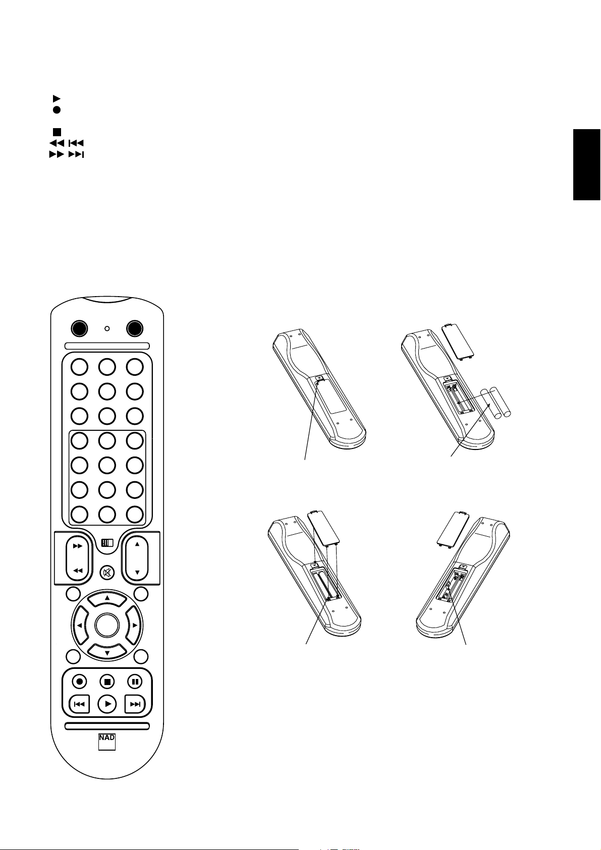
REMOTE CONTROL HANDSET (FIGURE 3)
The Remote Control handset handles all the key functions of the NAD
C 372 and has additional controls to remotely operate NAD Tuners,
Cassette and CD machines. It will operate up to a distance of 16ft (5m).
Alkaline batteries are recommended for maximum operating life. Four
AAA (R 03) batteries should be fitted in the battery compartment at the
back of the Remote Control handset. When replacing batteries, check
that they have been put in the right way round, as indicated on the base
of the battery compartment. Please refer to previous sections of the
manual for a full description of individual functions.
When a command from the remote control is received, the Standby/
protection indicator will blink. Note that the indicator may also blink
when receiving commands not necessarily for the C 372 but for other
components in the system.
MUTE
Press the MUTE Button to temporarily switch off the sound to the
speakers and headphones. Mute mode is indicated by the active input
indicator on the front panel flashing. Press MUTE again to restore sound.
Mute does not affect recordings made using the Tape outputs but will
affect the signal going to the Preamp outputs (Pre-Out 1 &2).
INPUTS
The input selector buttons perform the same functions as the buttons
labelled the same on the front panel.
MASTER VOLUME
Press the MASTER VOLUME or buttons to respectively
increase or decrease the loudness level. Release the button when the
desired level is reached. The motorised Volume Control on the front
panel will indicate the level set. The Master Volume buttons do not
affect recordings made using the Tape outputs but will affect the signal
going to the Pre-amp outputs (Pre-Out 1 &2).
TUNER CONTROL
(for use with NAD Tuner)
TUNE or scans respectively higher or lower station
frequencies for both AM and FM.
PRESET or selects respectively higher or lower number
station preset.
CD PLAYER CONTROL
(for use with NAD CD/DVD Player)
engages Pause
engages Stop
engages Play, toggles between Play and Pause or engages Track
skip; Press once to respectively go to the next track or to return to start
of current or previous track.
engages CD drawer Open/Close; Press once to open the CD
drawer then once again to close the CD drawer and start playback.
The TAPE/TUNER - CD switch applies tape controls to the transport keys
when in the TAPE/TUNER position, and applies CD controls to the
transport keys when in the CD position.
8
Page 9
CASSETTE DECK CONTROL
(for use with single NAD Cassette Decks)
engages Forward Play.
Press to put cassette deck into record-pause. Press Play to start
recording.
Stops Play or Recording.
engages Rewind.
engages Fast Forward.
The TAPE/TUNER - CD switch applies tape controls to the transport keys
when in the TAPE/TUNER position, and applies CD controls to the
transport keys when in the CD position.
REMOTE CONTROL (FIGURE 3)
ON
ON
CD
OFF
TUNER AUX
NOTES: The remote control handset supplied with the C 372 is of a
universal NAD type, designed to operate several NAD models. Some
buttons on this handset are inoperative as the functions aren't
supported by the C 372. The Video 2 and Video 3 input selector buttons
(inside section No. 2) on the remote control handset are inoperative in
the case of the C 372.
Direct sunlight or very bright ambient lighting may affect the operating
range and angle for the remote control handset.
ENGLISH
FRANÇAISDEUTSCHESPAÑOLITALIANO
DISC/PHONO
TUNE
VIDEO 1
1
4
7
10
SCAN
DISP
SPK
A
OPEN/CLOSE
SKIP
TAPE MON TAP E 2
VIDEO 2 VIDEO 3
3
2
5
6
9
8
+10
0
TAPE /
TUNER
CD
MUTE
PRESET
ENTER
PRESET
STOP
PLAY
VOL
PAUSE
SKIP
MONO
SPK
PRESS IN AND LIFT TAB TO REMOVE
BATTERY COVER OUT OF RECESS
PLACE BATTERIES INTO OPENING.
ENSURE THE CORRECT FITTING IS
OBSERVED
PORTUGUÊS
D
E
V
1
D
E
V2
TUNE
B
REPLACE BATTERY COVER BY
ALIGNING AND INSERTING THE TWO
TABS INTO THE HOLES.
PRESS BATTERY COVER INTO PLACE
UNTIL IT 'CLICKS' CLOSED
DEV.1 & DEV.2
SVENSKA
SR 5
9
Page 10
SPECIFICATIONS
AMPLIFIER SECTION
Power output Stereo Mode 2 x 170W
(8 ohms within rated distortion)
IHF dynamic power; 8 ohms 2 x 220W
IHF dynamic power; 4 ohms 2 x 340W
Total harmonic distortion at rated power 0.02%
IM distortion at rated power 0.003%
Damping factor 8 ohms >150
Input sensitivity and impedance 1.22 V / 20k ohms/470 pF
Frequency response 20 to 20,000 Hz ±0.3dB
Signal/noise ratio; ref rated power / 8 ohms (A-WTD) >120dB
Signal/noise ratio; ref 1W / 8 ohms (A-WTD) >100dB
Remote Control Yes, SR 5
Specifications are subject to change without notice.
For the latest information about your C 372, updated documentation and features please log onto www.nadelectronics.com
10
ENGLISH FRANÇAIS
DEUTSCH
ESPAÑOL
ITALIANO
PORTUGUÊS
SVENSKA
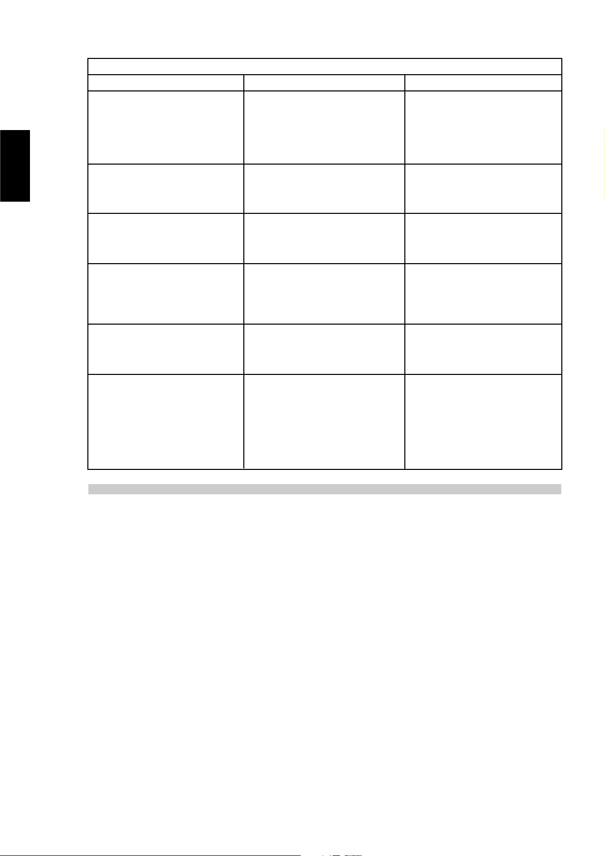
TROUBLESHOOTING
NO SOUND • Power AC lead unplugged or power not
switched on
• Tape 1 Monitor selected
• Mute on
• Rear Pre-out/Main-in amp links not fitted
• No speakers selected
• Check if AC lead is plugged in and power
switched on
• De-select Tape 1 Monitor mode
• Switch off Mute
• Fit links
• Select the appropriate speakers (A / B)
Problem Cause Solution
NO SOUND ONE CHANNEL • Balance control not centred
• Speaker not properly connected
or damaged.
• Input lead disconnected or damaged
• Centre Balance control
• Check connections and speakers
• Check leads and connections
WEAK BASS /
DIFFUSE OR NO STEREO IMAGE
• Speakers wired out of phase
• Bridge Mode selected when speakers are
connected normally
• Check connections to all speakers in the system
• Disengage Bridge Mode
REMOTE CONTROL HANDSET NOT WORKING • Batteries flat, or incorrectly inserted
• IR transmitter or receiver windows obstructed
• IR receiver in direct sun or very bright ambient
light
• Check or replace batteries
• Remove obstruction
• Place unit away from direct sun, reduce amount
of ambient light
POWER/PROTECTION LED STAYS RED UPON
TURNING POWER ON
• Loudspeakers cabling has a short-circuit • Turn amplifier off and check loudspeaker cable
connections for both speakers at amplifier's back
panel and loudspeakers. Turn amplifier on.
POWER/PROTECTION INDICATOR TURNS RED
DURING OPERATION
• Amplifier has over-heated.
• Overall impedance of loudspeakers too low
• Turn amplifier off. Make sure ventilation slots on
top and bottom of amplifier aren't blocked.
After amplifier has cooled down, turn back on.
• Ensure the overall loudspeaker impedance isn't
below 4 ohms.
• Check loudspeaker cables for short circuits
Page 11

11
ENGLISH
FRANÇAISDEUTSCHESPAÑOLITALIANO
PORTUGUÊS
SVENSKA
Page 12

MISE EN ROUTE RAPIDE
1 Brancher les haut-parleurs aux bornes des Haut-Parleurs A [Speaker
A] et brancher les sources aux prises d'entrées correspondantes.
2 Branchez le câble d'alimentation d'abord sur le C 372, puis sur une
prise murale.
3 Appuyer sur le bouton-poussoir "ALIMENTATION" [POWER] pour
mettre le NAD C 372 sous tension.
4 Appuyer sur le sélecteur d'entrée requis.
NOTES CONCERNANT L'INSTALLATION
Poser le NAD C 372 sur une surface stable, plane et horizontale. Eviter
les rayons directs du soleil et les sources de chaleur et d'humidité.
Assurer une ventilation adéquate. Ne pas poser cet appareil sur une
surface molle (moquette, par exemple). Ne pas le placer dans un endroit
confiné (sur une étagère de bibliothèque ou derrière des portes vitrées),
où le flux d'air à travers les ouïes de ventilation risque d'être entravé.
Vérifier que l'appareil est mis hors tension avant de réaliser des
connexions quelconques.
Pour vous faciliter la tâche, les bornes RCA de votre NAD C 372 sont
codées couleur. Rouge pour l'audio droite, blanc pour l'audio gauche, et
jaune pour la Liaison-NAD. N'utiliser que des câbles et des connecteurs
de très bonne qualité de manière à obtenir un branchement dont la
fiabilité est parfaite et les performances optimales. Vérifier que les câbles
et les connecteurs ne présentent aucune détérioration, et que tous les
connecteurs sont bien enfoncés jusqu'en butée.
Pour obtenir les meilleures performances, utiliser des câbles de hautparleurs d'une épaisseur égale ou supérieure au calibre 16 (1,5 mm) ou
plus. Si l'appareil doit rester inutilisé pendant un certain temps,
débrancher le cordon d'alimentation de la prise de secteur murale.
Si de l'eau pénètre à l'intérieur de votre NAD C 372, couper
l'alimentation de l'appareil et retirer la fiche de la prise secteur. Faire
contrôler l'appareil par un technicien de service après-vente qualifié,
avant toute tentative de remise en service. Ne pas retirer le
couvercle. A l'intérieur, il n'y a aucun élément sur lequel
l'utilisateur peut intervenir. Utiliser un chiffon doux sec et propre
pour nettoyer l'appareil. Si nécessaire, humecter le chiffon avec un
peu d'eau savonneuse. Ne pas utiliser de solution contenant du benzol
ou un quelconque autre agent volatile.
BRANCHEMENTS SUR LE PANNEAU ARRIERE (FIGURE 1)
1. ENTREE DISQUE
L'entrée pour les signaux d'entrée supplémentaires de niveau ligne, tels
qu'un lecteur CD, un lecteur Mini-Disc ou le signal de sortie provenant d'un
amplificateur rehausseur pour tourne-disques. Utiliser un câble jumelé RCA
vers RCA pour relier les connecteurs de "Sortie Audio" [Audio Outputs]
gauche et droit de l'appareil audio auxiliaire à cette entrée.
2. ENTREE CD
L'entrée pour un lecteur CD ou pour toute autre source de signal de
niveau ligne. Utiliser un câble jumelé RCA vers RCA pour relier les
connecteurs de sortie audio gauche et droit du lecteur CD à cette
entrée. Le NAD C 372 n'accepte que les signaux analogiques de votre
lecteur CD.
3. ENTREE VIDEO
Entrée pour le signal audio provenant d'un magnétoscope stéréo (ou
TV stéréo / Satellite / Récepteur de télédistribution) ou d'une autre
source audio de niveau ligne. En utilisant les câbles jumelés RCA vers
RCA, relier les connecteurs de "Sortie Audio" gauche et droit de
l'appareil à ces entrées. Nota : Il s'agit d'entrées audio uniquement.
4. ENTREE AUX
Entrée pour d'autres signaux de niveau ligne, comme un deuxième
lecteur CD par exemple. Utiliser un câble jumelé RCA vers RCA pour
relier les connecteurs de "Sortie Audio" [Audio Outputs] gauche et
droit de l'appareil audio auxiliaire à cette entrée.
5. ENTREE TUNER
L'entrée pour un tuner ou pour toute autre source de signal de niveau
ligne. Utiliser un câble jumelé RCA vers RCA pour relier les connecteurs
de "Sortie Audio" gauche et droit de l'appareil à cette entrée.
6. ENTREE / SORTIE “MAGNETOPHONE 2”
[TAPE 2 IN, OUT]
Branchements pour enregistrement et lecture analogiques sur un
magnétophone audio de type quelconque. En utilisant les câbles
jumelés RCA vers RCA, relier les connecteurs de "Sortie Audio"
gauche et droit du magnétophone aux prises d' "ENTREE
MAGNETOPHONE 2" [TAPE 2 IN] pour la lecture et le contrôle
d'enregistrement des bandes. Relier les connecteurs d' "Entrée Audio"
gauche et droit du magnétophone aux prises de "SORTIE
MAGNETOPHONE 2" [TAPE 2 OUT] pour l'enregistrement des bandes.
7. ENTREE / SORTIE “MAGNETOPHONE 1”
[TAPE 1 IN, OUT]
Branchements pour enregistrement et lecture analogiques sur un
deuxième magnétophone audio de type quelconque. En utilisant les
câbles jumelés RCA vers RCA, relier les connecteurs de "Sortie Audio"
gauche et droit du magnétophone aux prises d' "ENTREE
MAGNETOPHONE 1" [TAPE 1 IN] pour la lecture et le contrôle
d'enregistrement des bandes. Relier les connecteurs d' "Entrée Audio"
gauche et droit du magnétophone aux prises de "SORTIE
MAGNETOPHONE 1" [TAPE 1 OUT] pour l'enregistrement des bandes.
8. SORTIE PREAMPLI 1 [PRE OUT 1]
Pour une utilisation normale, la SORTIE PREAMPLI 1 [PRE OUT 1] est reliée
aux prises d'Entrée Principale [Main-In] (N° 9), à l'aide des cavaliers
fournis. Le NAD C 372 permet le branchement de plusieurs
amplificateurs de puissance. Si vous utilisez un seul amplificateur de
puissance stéréophonique, débranchez les cavaliers reliés aux prises
d'Entrée Principale [Main-In]. De cette façon, l'amplificateur de puissance
interne du C 372 est déconnecté. Utilisez un câble jumelé RCA vers RCA
pour relier les "Entrées Audio" gauche et droite de l'Amplificateur de
Puissance aux prises de "SORTIE PREAMPLI 1" [PRE OUT 1].
Si vous utilisez un amplificateur de puissance stéréophonique
spécifiquement conçu pour la fonction "Bi-amplificateurs", utilisez les
prises de "SORTIE PREAMPLI 1" pour brancher celui des deux
amplificateurs dont le gain est le plus faible. Voir aussi le chapitre "Biamplificateurs" pour de plus amples informations.
NOTES: Vous devez toujours mettre le C 372 et les amplificateurs
de puissance associés hors tension avant de brancher (ou de
débrancher) un quelconque appareil aux (des) prises SORTIE
PREAMPLI 1, 2 [PRE OUT 1, 2] ou ENTREE PRINCIPALE [MAIN-IN].
Les signaux de sortie des prises SORTIE PREAMPLI 1, 2 seront affectés
par le réglage des commandes de volume et de tonalité du NAD C 372.
12
ENGLISH FRANÇAIS
DEUTSCH
ESPAÑOL
ITALIANO
PORTUGUÊS
SVENSKA
Page 13

9. ENTREE PRINCIPALE [MAIN-IN]
Branchements à un amplificateur de puissance ou processeur externes,
tel qu'un décodeur de sonorisation enveloppante. Pour une utilisation
normale, ces entrées sont reliées aux prises de Sortie Préampli 1 [Pre-Out
1] (N° 8), à l'aide des cavaliers fournis. Pour brancher votre NAD C 372
à des modules processeurs ou d'amplificateur externes, il sera nécessaire
d'enlever ces liaisons d'abord. Utiliser un câble jumelé RCA vers RCA
pour brancher le connecteur de "Sortie Audio" [Audio-Output] gauche
et droit du préamplificateur ou processeur aux prises Main-In.
NOTES: Vous devez toujours mettre le C 372 et les amplificateurs
de puissance associés hors tension avant de brancher (ou de
débrancher) un quelconque appareil aux (des) prises SORTIE
PREAMPLI 1, 2 [PRE OUT 1, 2] ou ENTREE PRINCIPALE [MAIN-IN].
Les signaux de sortie des prises SORTIE PREAMPLI 1, 2 seront affectés
par le réglage des commandes de volume et de tonalité du NAD C 372.
10. SORTIE PREAMPLI 2 [PRE OUT 2]
Les prises de "SORTIE PREAMPLI 2" [PRE OUT 2] peuvent être
utilisées pour piloter un deuxième amplificateur de puissance. La
commande de VOLUME "Sortie Préampli 2" [Pre-Out 2] (N° 11)
permet de réduire le niveau de sortie du préamplificateur
alimentant l'amplificateur de puissance de jusqu'à -12 dB. Lorsque
la commande de VOLUME "Sortie Préampli 2" est réglée à sa
position maximale (position 0 dB), le niveau de sortie est identique
à celui des prises de "SORTIE PREAMPLI 1" [PRE OUT 1].
Si vous utilisez une paire d'amplificateurs de puissance spécifiquement
conçus pour la fonction "Bi-amplificateurs", utilisez les prises de
"SORTIE PREAMPLI 2" pour brancher celui des deux amplificateurs dont
le gain est le plus fort. En jouant sur la commande de VOLUME "SORTIE
PREAMPLI 2" (N° 11), il est possible d'accorder avec précision le volume
de sortie de cet amplificateur de puissance à celui de l'amplificateur
connecté aux prises de "SORTIE PREAMPLI 1" (PRE OUT 1). Voir aussi le
chapitre "Bi-amplificateurs" pour de plus amples informations.
Utilisez un câble jumelé RCA vers RCA pour relier les "Entrées Audio"
gauche et droite de l'Amplificateur de Puissance aux prises de "SORTIE
PREAMPLI" [PRE OUT] 1 et 2.
NOTES: Vous devez toujours mettre le C 372 et les amplificateurs
de puissance associés hors tension avant de brancher (ou de
débrancher) un quelconque appareil aux (des) prises SORTIE
PREAMPLI 1, 2 [PRE OUT 1, 2] ou ENTREE PRINCIPALE [MAIN-IN].
Les signaux de sortie des prises SORTIE PREAMPLI 1, 2 seront affectés
par le réglage des commandes de volume et de tonalité du NAD C 372.
11. VOLUME SORTIE PREAMPLI 2 [VOLUME PRE OUT 2]
La commande de VOLUME "SORTIE PREAMPLI 2" [PRE OUT 2] permet
de régler le niveau de sortie des PRISES DE "SORTIE PREAMPLI 2" [PRE
OUT 2]. Il est possible de diminuer le niveau de sortie du
préamplificateur alimentant l'amplificateur de puissance de 0 dB à -12
dB ; lorsque la commande est réglée à sa position maximale (position 0
dB), le niveau de sortie est identique à celui des prises de "SORTIE
PREAMPLI 1" [PRE OUT 1]. Voir aussi le chapitre "Bi-amplificateurs"
pour de plus amples informations.
NOTES: Vous devez toujours mettre le C 372 et les amplificateurs
de puissance associés hors tension avant de brancher (ou de
débrancher) un quelconque appareil aux (des) prises SORTIE
PREAMPLI 1, 2 [PRE OUT 1, 2] ou ENTREE PRINCIPALE [MAIN-IN].
Les signaux de sortie des prises SORTIE PREAMPLI 1, 2 seront affectés
par le réglage des commandes de volume et de tonalité du NAD C 372.
12. MODE PONTE
Il est possible, en connectant des amplificateurs de puissance
supplémentaires, d'utiliser le NAD C 372 comme module d'une chaîne
stéréophonique plus puissante ou d'une chaîne de cinéma à domicile. Si
la section amplificateur de puissance du NAD C 372 va être utilisée pour
alimenter un seul haut-parleur, utilisez le sélecteur de Pontage [Bridge]
pour faire fonctionner les amplificateurs intégrés droit et gauche comme
un ensemble à voie unique de grande puissance. Mettez le sélecteur de
MODE PONTE [BRIDGE MODE] à la position "Ponté" [Bridge] et
branchez le haut-parleur aux bornes repérées "L+" et "R+", en vous
assurant que la borne "L+" est reliée à la borne "+" du haut-parleur et
que la borne "R+" est reliée à la borne "-" du haut-parleur. Connectez
la source à l'ENTREE PRINCIPALE [MAIN IN] gauche.
En Mode Ponté, le NAD C 372 aura une puissance de sortie d'environ
300 W avec un haut-parleur de 8 ohms. Dans ce mode, les sections
fonctionneront comme si l'impédance du haut-parleur avait été divisée
par deux. Pour cette raison, il est déconseillé d'utiliser des haut-parleurs
de faible impédance (moins de 8 ohms) en Mode Ponté, car cela
risquerait de provoquer le déclenchement du dispositif de coupure
thermique lorsque l'amplificateur fonctionne à puissance élevée.
La LED Ponté [Bridge] de la face parlante (Fig. 2 ; N° 2) s'allumera
lorsque l'amplificateur fonctionnera en mode Ponté.
NOTES: Ne branchez rien sur l'ENTREE PRINCIPALE [MAIN IN] droite
(N° 9) lorsque le Mode Ponté est sélectionné.
Vous devez toujours mettre le C 372 et les amplificateurs de
puissance associés hors tension avant de brancher (ou de
débrancher) un quelconque appareil aux (des) prises SORTIE
PREAMPLI 1,2 [PRE OUT 1, 2] ou ENTREE PRINCIPALE [MAIN-IN].
13. ECRETAGE DOUX [SOFT CLIPPING™]
Lorsqu'un amplificateur est poussé au-delà de sa puissance de sortie
spécifiée, on entend un son dur et déformé lors des passages à sonorité
forte. Cela provient du fait que l'amplificateur coupe ou "écrête de
façon dure" les pointes sonores pour lesquelles sa conception ne permet
pas la reproduction. Le circuit d'écrêtage doux, de NAD, limite en
douceur la forme d'onde à la sortie, pour minimiser la distorsion audible
lorsque l'amplificateur est poussé au-delà de ses limites.
Si votre écoute comporte des niveaux modérés de puissance, vous
pouvez laisser l'Ecrêtage Doux sur ARRET [OFF].. Si, par contre, vous
pensez passer de la musique à des niveaux très élevés, susceptibles de
dépasser la capacité de puissance de l'amplificateur, nous préconisons
de mettre l'Ecrêtage Doux sur "MARCHE" [ON]. L'indicateur
d'Ecrêtage Doux sur la face parlante s'allume lorsque l'amplificateur
est en mode Ecrêtage Doux.
13
ENGLISH
FRANÇAISDEUTSCHESPAÑOLITALIANO
PORTUGUÊS
SVENSKA
Page 14

14. ENTRÉE / SORTIE IR
Le connecteur d'ENTRÉE / SORTIE IR [IR IN/OUT] sert à relayer les
commandes en provenance d'autres appareils équipés de l'ENTRÉE /
SORTIE IR. Ceci permet de commander le système entier depuis un
point central, et assure aussi quelques fonctions de base pour d’autres
composants NAD (tels que le tuner, le lecteur de CD ou le lecteur de
cassettes) pourvus également d’une ENTRÉE / SORTIE IR [IR IN/OUT] qui
est commandée par la télécommande de l’amplificateur. Pour
permettre le fonctionnement avec d'autres appareils, reliez la SORTIE IR
[IR OUT] du C 372 à l'ENTRÉE IR [IR IN] de l'autre appareil. Il est possible
de relier les connecteurs IR en chaîne, ENTRÉE vers SORTIE, et donc de
commander tout un réseau d'appareils à l'aide de la télécommande
d'un seul d'entre eux.
NOTES : Il est conseillé de ne pas connecter l'ENTRÉE / SORTIE IR [IR
IN/OUT] si ces appareils comportent leur propre récepteur de
télécommande intégré et qu'ils sont situés au même endroit, à portée
directe de la télécommande. En cas de doute, commencez par essayer
de faire fonctionner les appareils sans l'ENTRÉE / SORTIE IR ; si l'appareil
réagit à la commande émise par le combiné de télécommande, il ne
sera pas nécessaire de connecter l'ENTRÉE / SORTIE IR. Ne reliez jamais
le dernier appareil de la chaîne ENTRÉE / SORTIE IR au premier.
Débranchez tous les appareils du secteur avant de brancher ou de
débrancher l'ENTRÉE / SORTIE IR.
15. SORTIE “ASSERVISSEMENT 12 V” [12 V TRIGGER]
Cette sortie permet de télécommander la mise en marche ou l'arrêt
d'appareils auxiliaires comme par exemple un tuner, un amplificateur
de puissance etc., dans la mesure où ces appareils sont aussi équipés
d'une entrée d'asservissement 12V. Il est aussi possible de
télécommander une barrette de prises secteur équipée d'une entrée
d'asservissement 12V. La sortie d'asservissement 12V est activée
chaque fois que l'appareil est commuté en mode de fonctionnement
normal à partir du mode Veille ou Arrêt.
Pour commuter un appareil externe entre les modes Veille et Marche, à
travers le C 372, brancher la sortie asservissement 12 V du C 372 au jack
d'entrée CC de l'appareil concerné. Le connecteur requis est une fiche
Mini-Jack standard de 3,5 mm ("mono") : L'extrémité de la fiche jack
correspond au "+" et la tige correspond à l'asservissement 12 V, c'est
à dire au "-" ou à la masse.
NOTES: Vérifier les spécifications de la borne d'entrée d'Asservissement
sur les autres appareils pour s'assurer de leur compatibilité avec la sortie
Asservissement 12 V du C 372. Tous les appareils NAD équipés d'un
Asservissement 12 V sont entièrement compatibles avec la sortie
Asservissement 12 V du C 372.
La tension de sortie de l'Asservissement 12 V du C 372 est de 12 V CC.
Le courant total maximum consommé ne doit pas dépasser 200 mA.
Typiquement, les asservissements 12 V NAD consomment un courant
inférieur à 10 mA.
Avant de réaliser un quelconque branchement à une entrée ou à une
sortie d'Asservissement 12 V, s'assurer que tous les appareils sont
débranchés du secteur.
Tout non respect de la consigne ci-dessus pourrait provoquer la
détérioration du C 372 ou de tout appareil auxiliaire qui lui est connecté.
En cas de doute concernant les branchements, l'installation et l'utilisation
de la sortie d'Asservissement 12 V, consultez votre revendeur NAD.
16. HAUT-PARLEURS A + HAUT-PARLEURS B
Le NAD C 372 est équipé de deux jeux de connecteurs pour les hautparleurs. Utilisez les connecteurs Haut-Parleurs A [Speakers A] pour
connecter les haut-parleurs "principaux" et utilisez les connecteurs
Haut-Parleurs B [Speakers B] pour connecter (par exemple) une
deuxième paire de haut-parleurs située dans une autre pièce.
En fonctionnement normal, connectez le haut-parleur droit aux bornes
repérées "R+" et "R-", en vous assurant que la borne "R+" est reliée à
la borne "+" du haut-parleur et que la borne "R-" est reliée à la borne
"-" du haut-parleur.
Brancher les bornes repérées "L+" et "L-" au haut-parleur gauche en
procédant de la même manière.
En Mode "Ponté" [Bridge], branchez le haut-parleur unique aux bornes
repérées "R+" et "L+" en vous assurant que la borne "L+" est reliée à
la borne "+" de votre haut-parleur et que la borne "R+" est reliée à la
borne "-" du haut-parleur. Reportez-vous aussi à la section "Mode
Ponté" de ce même chapitre (N° 12).
N'utiliser que du fil torsadé haute puissance (calibre 16 ; 1,5 mm ou
plus) pour brancher les haut-parleurs à votre NAD C 372. On peut
utiliser les bornes pour courants élevés comme bornes à visser pour les
câbles comportant des cosses plates, des broches ou des fils nus.
FILS NUS ET BORNES A BROCHES
Les fils nus et les broches s'insèrent dans le trou diamétral percé dans la
tige de la borne. Desserrer la bague en plastique de la borne de hautparleur jusqu'à ce que le trou axial dans la tige soit visible. Insérer la
broche ou le fil nu dans le trou, puis fixer le câble en vissant la bague de
la borne. Veiller à ce qu'aucun fil nu des câbles des haut-parleurs ne
touche le panneau arrière ou une autre prise. Veiller à ce qu'il n'y ait que
1 cm de fil nu ou de broche et qu'il n'y ait aucun brin libre sur les fils des
haut-parleurs.
NOTA: Assurez-vous que l'impédance des haut-parleurs est d'au moins
4 ohms si vous ne connectez qu'une paire de haut-parleurs ; assurezvous que l'impédance de tous les haut-parleurs est d'au moins 8 ohms
si vous connectez deux paires de haut-parleurs. En Mode Ponté,
l'impédance du haut-parleur unique doit aussi être d'au moins 8 ohms.
17. PRISE SECTEUR AUXILIAIRE COMMUTEE
Le cordon secteur d'un autre appareil pourra être branché sur cette
prise auxiliaire. Les appareils branchés sur cette prise seront commutés
entre Marche et Arrêt par le bouton d' "ALIMENTATION" [POWER] sur
la face parlante, ou par les boutons "MARCHE" [ON] et "VEILLE"
[STAND-BY] de la télécommande.
NOTA: La consommation totale de tous les modules connectés aux
sorties secteur ne doit pas dépasser 100 Watts.
18. ENTRÉE ALIMENTATION EN CA C.I.E.
L’appareil NAD C 372 est fourni avec un cordon d’alimentation CA
détachable. Avant de brancher le cordon dans une prise de secteur
murale sous tension, il faut d’abord vérifier que le cordon soit bien
enfoncé jusqu’en butée dans la prise d’entrée alimentation CA du
C 372. Toujours débrancher le cordon de la prise de secteur murale
d’abord, avant de débrancher le cordon de la prise d’entrée
alimentation sur le C 372.
14
ENGLISH FRANÇAIS
DEUTSCH
ESPAÑOL
ITALIANO
PORTUGUÊS
SVENSKA
Page 15
15
ENGLISH
FRANÇAISDEUTSCHESPAÑOLITALIANO
PORTUGUÊS
SVENSKA
COMMANDES SUR LA FACE PARLANTE (FIGURE 2)
1. “MARCHE / ARRET” [POWER ON/OFF]
Appuyer sur le bouton "MARCHE" [POWER] pour mettre
l'amplificateur sous tension. La lampe témoin de "Veille" [Stand-by]
(N° 2) au dessus du bouton Marche s'allume en rouge puis, après un
court laps de temps, passe au vert pour indiquer que l'amplificateur
est prêt à fonctionner normalement. Le fait d'appuyer à nouveau sur
le bouton "MARCHE" [POWER] mettra l'appareil complètement
hors tension ; il ne réagira plus à la télécommande.
TÉLÉCOMMANDE (FIGURE 3)
ET BOUTONS MARCHE / ARRÊT
Appuyez sur le bouton MARCHE [POWER] (N° 1) pour mettre
l'amplificateur sous tension. Le témoin de Veille (N° 2) s'allume en orange
au dessus du bouton Marche. Le fait d'appuyer à nouveau sur le bouton
MARCHE [POWER] mettra l'appareil complètement hors tension ; il ne
réagira plus à la télécommande. La télécommande NAD C 372 est dotée
de boutons Marche [On] et Arrêt [Off] distincts. Ceci est particulièrement
utile pour maintenir la synchronisation des appareils constituant la chaîne
: De cette manière, tous les appareils passeront en mode Veille lorsque
vous appuierez sur ARRÊT [Off], ou passeront en mode Marche lorsque
vous appuierez sur ON [Marche], plutôt que de se mettre en Marche
lorsque vous mettrez l'amplificateur en mode Veille. (A noter que les
autres appareils doivent eux aussi être capables de répondre à des
commandes de Marche / Arrêt distinctes). Appuyez sur le bouton
MARCHE [ON] pour faire passer l'appareil du mode Veille au mode
Marche ; la lampe témoin de Veille (Fig. 2, N° 2) passera de l'orange au
rouge, puis au vert et la lampe témoin de la dernière source sélectionnée
clignotera puis s'allumera. Appuyez sur le bouton OFF pour mettre
l'appareil en mode Veille : La lampe témoin de Veille passera à l'orange.
NOTA: Le C 372 ne consomme que très peu de courant en mode
Veille. Toutefois, si l'appareil doit rester inutilisé pendant plusieurs
jours, nous préconisons de le mettre hors tension. Pour mettre
l'appareil hors tension, appuyer sur le bouton "Marche-Arrêt"
[POWER] (N° 1) de la face parlante; tous les voyants s'éteindront.
2. LAMPE TÉMOIN DE VEILLE / PROTECTION
[STAND-BY/PROTECTION]
Lorsque vous mettez l'appareil sous tension, la LED s'allume en orange
pour indiquer l'état de veille. Lorsque vous appuyez sur l'un des boutons
de sélection d'entrée, la LED s'allume momentanément en rouge puis
passe au vert (état de MARCHE). En cas d'importante surcharge de
l'amplificateur, comme par exemple l'utilisation d'un haut-parleur
d'impédance très faible, de court-circuit, etc ..., les circuits de protection
de l'amplificateur entrent en jeu ; cet état est indiqué par le passage au
rouge du LED, et par la coupure du son. Dans un cas comme celui-ci,
mettez l'amplificateur hors tension, attendez qu'il refroidisse et vérifiez le
branchement des haut-parleurs ; vérifiez aussi que l'impédance globale
des haut-parleurs ne passe pas en dessous de 4 ohms. Une fois que vous
aurez éliminé la cause du problème, appuyez à nouveau sur le bouton
d'Alimentation [Power] pour reprendre le fonctionnement normal.
Le schéma ci-dessous montre le fonctionnement de la lampe témoin de
Veille / Protection:
3. PRISE “CASQUE” [HEADPHONE]
Une prise stéréo pour fiche à jack de 1/4" est prévue pour l'écoute avec
casque et convient aux casques conventionnels à impédance
quelconque. La prise casque fonctionnera en parallèle avec les hautparleurs sélectionnés. Pour écouter uniquement avec le casque,
désélectionnez les Haut-Parleurs A et/ou B (N° 4).
Les commandes de volume sonore, de tonalité et de balance agissent
aussi sur l'écoute sur casque. Utiliser un adaptateur approprié pour
brancher des casques équipés d'un autre type de connecteur, tel qu'un
jack stéréophonique de 3,5 mm de type "baladeur stéréo".
NOTA: Vérifiez que la commande de volume sonore est au minimum
(butée anti-horaire) avant de brancher ou de débrancher le casque.
L'écoute à des niveaux sonores élevés peut entraîner des dommages
auditifs permanents.
4. HAUT-PARLEURS [SPEAKERS] A & B
Les boutons Haut-Parleurs [Speakers] A et B activent ou désactivent les
haut-parleurs connectés aux bornes Haut-Parleurs A [Speakers A] et
Haut-Parleurs B [Speakers B], respectivement, sur le panneau arrière.
Appuyez sur A pour activer ou désactiver les haut-parleurs connectés
aux bornes Haut-Parleurs A. Appuyez sur B pour activer ou désactiver les
haut-parleurs connectés aux bornes Haut-Parleurs B. La lampe témoin à
l'aplomb des boutons indique l'état des haut-parleurs A et B.
En cas d'activation simultanée des Haut-Parleurs A et B (les lampes
témoins au dessus des deux boutons "A" et "B" sont allumées), la
puissance de sortie de l'amplificateur alimente les deux paires de hautparleurs en parallèle. Si les deux paires de haut-parleurs sont
désactivées, elles resteront silencieuses. Dans ce dernier cas, vous
pouvez écouter avec le casque (N° 3).
NOTES: Baissez toujours le volume sonore lorsque vous activez ou
désactivez les Haut-parleurs A ou B.
Lorsque vous utilisez les Haut-parleurs A et B en même temps, assurezvous que l'impédance des haut-parleurs connectés est supérieure à 8
ohms. Reportez-vous au tableau ci-dessous:
Vert Orange Rouge
Fonctionnement normal •
Veille •
Protection •
Mode Ponté Mode Stéréo
Un haut-parleur de 81 minimum Un haut-parleur de 41 minimum
Deux haut-parleurs de 161 minimum Deux haut-parleurs de 81 minimum
Page 16

5. SELECTEURS D’ENTREES
Ces boutons permettent de sélectionner l'entrée active du NAD C 372
ainsi que le signal envoyé aux haut-parleurs, aux sorties Magnétophone
et aux prises PRE OUT.
Les boutons sur la télécommande sont identiques à ces boutons, à
l'exception de l'entrée tuner; voir ci-dessous. Une lampe témoin verte, à
l'aplomb de chaque bouton, indique l'entrée active.
DISC Sélectionne, comme entrée active, une source de niveau ligne
branchée aux prises DISC.
CD Sélectionne, comme entrée active, le lecteur CD (ou une source de
niveau ligne) branchée aux prises CD.
VIDEO Sélectionne, comme entrée active, le magnétoscope (ou un
téléviseur stéréo/décodeur satellite/récepteur de télédistribution)
connecté aux prises VIDEO.
AUX Sélectionne, comme entrée active, une source de niveau ligne
branchée aux prises AUX.
TUNER Sélectionne, comme entrée active, le tuner (ou une source de
niveau ligne) branché aux prises Tuner.
“MAGNETOPHONE 2” [TAPE 2] Sélectionne "Magnétophone 2"
[Tape 2] comme l'entrée active.
Moniteur “MAGNETOPHONE 1” [TAPE 1] Sélectionne la sortie d'un
magnétophone lors de la lecture de cassettes ou du suivi
d'enregistrements à partir des prises "Magnétophone 1" [Tape 1].
Appuyer une fois sur le bouton "Magnétophone 1" [Tape 1] pour
l'activer et une deuxième fois pour rétablir la sélection d'entrée normale.
"Magnétophone 1" [Tape 1] est une fonction de suivi magnétophone
qui n'annule pas la sélection d'entrée en cours. Par exemple, si le CD est
l'entrée active lorsque TAPE 1 est sélectionné, le signal CD continue
d'être sélectionné et est envoyé aussi bien aux prises de sortie TAPE 2 et
TAPE 1, mais c'est le son du magnétophone relié à TAPE 1 qui sera
entendu sur les haut-parleurs. En plus de la lampe témoin orange
indiquant le fonctionnement du Magnétophone 1, la lampe témoin
verte de l'entrée active restera allumée elle aussi.
NOTA: Le combiné de télécommande fourni avec le C 372 est de type
NAD Universel ; il est conçu pour fonctionner avec plusieurs modèles
d'appareils NAD. Certains boutons de ce combiné ne fonctionnent pas
car les fonctions concernées ne sont pas supportées par le C 372. Les
boutons de sélection d'entrée Vidéo 2 et Vidéo 3 sur la télécommande
ne fonctionnent pas dans le cas du C 372.
6. RECEPTEUR INFRAROUGE DE TELECOMMANDES
Le capteur infrarouge, situé derrière cette fenêtre circulaire, reçoit les
commandes de la télécommande. L'espace entre la télécommande et le
récepteur doit être dégagé de tout obstacle, sinon la télécommande
peut refuser de fonctionner.
NOTES: Lors de la réception d'une commande en provenance du
combiné de télécommande, la lampe témoin "Veille / Protection"
[Stand-by/Protection] clignote. A noter que la lampe témoin peut aussi
clignoter lors de la réception d'autres télécommandes, même si elles ne
sont pas destinées au C 372 mais à d'autres modules de la chaîne. La
portée et l'angle d'utilisation du combiné de télécommande risquent
d'être réduits en présence d'un fort éclairage (lumière du soleil ou
éclairage fluorescent très puissant).
7. INDICATEUR D’ECRETAGE DOUX [SOFT CLIPPING™]
L'indicateur vert d'ECRETAGE DOUX indique que le mode d'Ecrêtage
[Doux Soft Clipping™] est actif. Reportez-vous aussi au chapitre
"Branchements sur le panneau arrière", section 13 "Ecrêtage Doux",
pour de plus amples informations.
8. COMMANDES DES “GRAVES” [BASS]
ET DES “AIGUS” [TREBLE]
Le NAD C 372 est équipé de commandes de "GRAVES" [BASS] ET d'
"AIGUS" [TREBLE], qui permettent de régler la tonalité globale de votre
chaîne. La position médiane (12 heures) correspond à une courbe plate,
sans amplification ni atténuation; un léger déclic peut être ressenti dans
le mouvement du bouton à cet endroit. Tourner le bouton en sens
horaire pour amplifier les Graves ou les Aigus. Tourner le bouton en sens
anti-horaire pour atténuer les Graves ou les Aigus. Les commandes de
Tonalité n'affectent pas les enregistrements faits au moyen des Sorties
"Magnétophone" [TAPE] mais agissent toutefois sur le signal allant vers
les "Sorties de Préamplification" [Pre-Out 1 & 2].
9. “TONALITE NEUTRE” [TONE DEFEAT]
L'interrupteur de "TONALITE NEUTRE" [TONE DEFEAT] contourne la
section de commande de la tonalité du NAD C 372. Si l'on n'utilise pas
les commandes de tonalité, c'est à dire si elles restent toujours en
position médiane (12 heures), il est conseillé de mettre les dispositifs de
réglage de la tonalité complètement hors circuit grâce à ce boutoninterrupteur. Si le bouton n'est pas enfoncé, les circuits de tonalité sont
actifs; le fait d'enfoncer le bouton "TONALITE NEUTRE" [TONE DEFEAT]
contourne les circuits de réglage de la tonalité.
10. BALANCE
La commande BALANCE règle les niveaux relatifs des haut-parleurs
gauche et droit. La position médiane (12 heures) assure un niveau égal
pour les voies gauche et droite. Un léger déclic peut être ressenti dans
le mouvement du bouton à cet endroit.
En tournant le bouton en sens horaire, on déporte l'équilibre vers la
droite. En tournant le bouton en sens anti-horaire, on déporte l'équilibre
vers la gauche. La commande de BALANCE n'affecte pas les
enregistrements faits au moyen des Sorties "Magnétophone" [TAPE]
mais agit toutefois sur le signal allant vers les "Sorties de
Préamplification" [Pre-Out 1 et 2].
11. VOLUME
La commande de VOLUME sonore règle le volume global des signaux
envoyés aux haut-parleurs. Elle est motorisée et peut être réglée depuis
la télécommande. La commande de VOLUME n'affecte pas les
enregistrements faits au moyen des Sorties "Magnétophone" [TAPE]
mais agit toutefois sur le signal allant vers les "Sorties de
préamplification" [Pre-Out 1 et 2].
12. INDICATEUR DE MODE PONTE [BRIDGE MODE]
L'indicateur de MODE PONTE s'allume (orange) lorsque le C 372 est
en Mode Ponté. Reportez-vous aussi au chapitre "Branchements sur
le panneau arrière", section 12 "Ecrêtage Doux" pour de plus
amples informations.
ENREGISTREMENT
Lorsqu'une source est sélectionnée, son signal est aussi envoyé
directement à un quelconque magnétophone relié aux SORTIES
"MAGNETOPHONE 2" ou "MAGNETOPHONE 1" [TAPE 2 ou TAPE 1]
pour l'enregistrement.
“COPIER ENTRE CASSETTES” [TAPE TO TAPE]
Il est possible de réaliser des copies entre deux magnétophones
connectés à votre NAD C 372. Mettre la bande source sur le
magnétophone connecté à "Magnétophone 2" [Tape 2] et la bande
vierge sur le magnétophone connecté à "Magnétophone 1" [Tape 1].
En sélectionnant l'Entrée "MAGNETOPHONE 2" [TAPE 2], il est possible
d'enregistrer de "Magnétophone 2" à "Magnétophone 1", et de
contrôler le signal en provenance de la bande d'origine.
16
ENGLISH FRANÇAIS
DEUTSCH
ESPAÑOL
ITALIANO
PORTUGUÊS
SVENSKA
Page 17

17
ENGLISH
FRANÇAISDEUTSCHESPAÑOLITALIANO
PORTUGUÊS
SVENSKA
BI-AMPLIFICATEURS
COMBINE DE TELECOMMANDE (FIGURE 3)
La Télécommande reproduit toutes les fonctions clés du NAD C 372, et
comporte aussi des commandes supplémentaires permettant de
télécommander les Tuners, les Magnétophones et les Lecteurs de CD
NAD. Elle fonctionne depuis une distance pouvant aller jusqu'à 5
mètres. Il est conseillé d'utiliser des piles alcalines pour une longévité
maximale. Quatre piles de type AAA (R 03) doivent être insérées dans le
compartiment des piles à l'arrière du combiné Télécommande. Lors du
remplacement des piles, assurez-vous de leur bonne orientation
conformément au dessin dans le fond du compartiment des piles.
Reportez-vous aux sections précédentes du manuel pour des
descriptions détaillées des différentes fonctions.
Lors de la réception d'une commande en provenance du combiné de
télécommande, la lampe témoin "Veille / Protection" [Standby/Protection] clignote. A noter que la lampe témoin peut aussi clignoter
lors de la réception d'autres télécommandes, même si elles ne sont pas
destinées au C 372 mais à d'autres modules de la chaîne.
MARCHE / ARRET ALIMENTATION
La télécommande NAD C 372 est dotée de boutons Marche [On] et
Arrêt [Off] distincts. Ceci est particulièrement utile pour maintenir la
synchronisation des appareils constituant la chaîne : De cette manière,
tous les appareils passeront en mode Veille lorsque vous appuierez sur
"Arrêt" [Off], ou passeront en mode Marche lorsque vous appuierez
sur "On" [Marche], plutôt que de se mettre en Marche lorsque vous
mettrez l'amplificateur en mode Veille. (A noter que les autres
appareils doivent eux aussi être capables de répondre à des
commandes de Marche / Arrêt distinctes). Appuyez sur le bouton
MARCHE [ON] pour faire passer l'appareil du mode Veille au mode
Marche ; la lampe témoin de Veille (Fig. 2, N° 2) passera de l'orange
au rouge, puis au vert et la lampe témoin de la dernière source
sélectionnée clignotera puis s'allumera. Appuyez sur le bouton OFF
pour mettre l'appareil en mode Veille : La lampe témoin de Veille
passera à l'orange.
HAUT-PARLEURS A & B
Ces boutons assurent la même fonction que ceux de la face parlante.
Les boutons Haut-Parleurs [Speakers] A et B activent ou désactivent les
haut-parleurs connectés aux bornes Haut-Parleurs A [Speakers A] et
Haut-Parleurs B [Speakers B], respectivement, sur le panneau arrière.
Appuyez sur A pour activer ou désactiver les haut-parleurs connectés
aux bornes Haut-Parleurs A. Appuyez sur B pour activer ou désactiver les
haut-parleurs connectés aux bornes Haut-Parleurs B. La lampe témoin à
l'aplomb des boutons indique l'état des haut-parleurs A et B.
“SILENCIEUX DE RECHERCHE” [MUTE]
Appuyez sur le bouton "Silencieux" [MUTE] pour couper provisoirement
l’émission du son vers les haut-parleurs et le casque. Le mode Silencieux
est indiqué par le clignotement de la lampe témoin de l'entrée active sur
la face parlante. Réappuyez sur "SILENCIEUX" [MUTE] pour rétablir le
son. La commande Mute n’affecte pas les enregistrements faits au
moyen des Sorties "Magnétophone" [TAPE] mais agit toutefois sur le
signal allant vers la "Sortie de Préamplification" [Pre-Out 1 & 2].
ENTREES
Les boutons de sélection des entrées ont les mêmes fonctions que les
boutons repérés de façon identique sur la face parlante.
Certains haut-parleurs comportent des branchements distincts pour
les sections BF (Basses Fréquences) et HF (Hautes Fréquences) de
l'enceinte. Ce dispositif permet d'utiliser ces haut-parleurs en mode
"Bi-Amplificateurs", grâce auquel un amplificateur de puissance
distinct est utilisé pour chaque section, BF et HF. Cela peut améliorer
la qualité globale de la sonorité.
Le NAD C 372 comporte deux jeux de sorties préamplificateur
"SORTIES PREAMPLI 1 & 2" [PRE OUT 1 & 2], afin de faciliter les
branchements en mode bi-amplificateurs. En outre, il est possible de
diminuer le niveau de sortie de "SORTIE PREAMPLI 2" [PRE OUT 2] par
rapport à celui de la sortie "SORTIE PREAMPLI 1" [PRE OUT 1], ce qui
permet d'utiliser des amplificateurs de puissance dont le gain (facteur
d'amplification) n'est pas identique.
Pour configurer le C 372 avec des amplificateurs de puissance, commencer
par décider lequel des deux a le gain le plus élevé. Pour cela, il suffit tout
simplement de comparer le volume sonore des deux amplificateurs de
puissance sur une chaîne identique (la commande de volume sonore doit
être maintenue au même niveau et il faut utiliser la même source et les
mêmes haut-parleurs). L'amplificateur qui produit le son le plus fort a le gain
le plus élevé (à noter qu'il ne s'agira pas forcément du plus puissant des deux
amplificateurs). Brancher l'amplificateur doté du gain le plus élevé aux prises
"SORTIE PREAMPLI 2" [PRE OUT 2] (N° 10) ; brancher l'autre amplificateur
de puissance aux prises "SORTIE PREAMPLI 1" [PRE OUT 1] (N° 8).
A partir
de la position de niveau maximum (0 dB), régler la commande de
"VOLUME DE SORTIE PREAMPLI 2" [VOLUME PRE OUT 2] (N° 11) pour
réduire le niveau de sortie de "SORTIE PREAMPLI 2" [PRE OUT 2] de
manière à ce que le niveau sonore des deux amplificateurs de puissance
soit parfaitement apparié.
NOTES: Le gain de l'amplificateur de puissance NAD C 272 est identique
à celui de l'amplificateur intégré du C 372 (en fait, le C 272 et la section
amplificateur de puissance du C 372 sont pratiquement identiques).
Lorsque le C 372 est utilisé avec un NAD C 272 en mode BiAmplificateurs, laissez la SORTIE PREAMPLI 1 [PRE-OUT 1] connecté,
grâce aux cavaliers fournis, à l'ENTREE PRINCIPALE [MAIN IN]. Connectez
le C 272 à la SORTIE PREAMPLI 2 [PRE-OUT 2]. Réglez la commande de
VOLUME PREAMPLI 2 [PRE-OUT 2] à sa position maximum.
Les cavaliers fournis pour relier la SORTIE PREAMPLI 1 [PRE-OUT 1] à
l'ENTREE PRINCIPALE [MAIN IN] peuvent aussi être utilisés pour relier la
SORTIE PREAMPLI 2 [PRE-OUT 2] à l'ENTREE PRINCIPALE [MAIN IN], dans
le cas où l'amplificateur de puissance du C 372 aurait le gain le plus
élevé. Désalimentez toujours le C 372 et les amplificateurs externes
avant de connecter ou de déconnecter un appareil quelconque aux
prises de Sortie Préampli et/ou d'ENtrée Principale.
POWERDRIVE
Afin de répondre aux différentes exigences d'alimentation haute
intensité et de puissance dynamique élevée, notre circuit d'amplification
breveté PowerDrive bénéficiera des technologies qui ont fait notre
réputation en matière de puissance vraiment efficace. En ajoutant un
deuxième conducteur haute tension à notre source de courant haute
intensité parfaitement régulée, nous obtenons une "surpuissance"
pouvant presque doubler la puissance continue lorsqu'il s'agit d'une
puissance dynamique de courte durée.
Il s'agit d'une autre évolution de notre fameux circuit Power Envelope,
utilisé par NAD dans les années 80 et 90. La différence entre Power
Envelope et PowerDrive est que ce dernier assure une meilleure stabilité
de l'amplificateur et que sa capacité de piloter de faibles impédances est
plus remarquable ; la distorsion est donc moindre lorsque les circuits
pilotent de véritables haut-parleurs à partir d'une source réelle.
Page 18
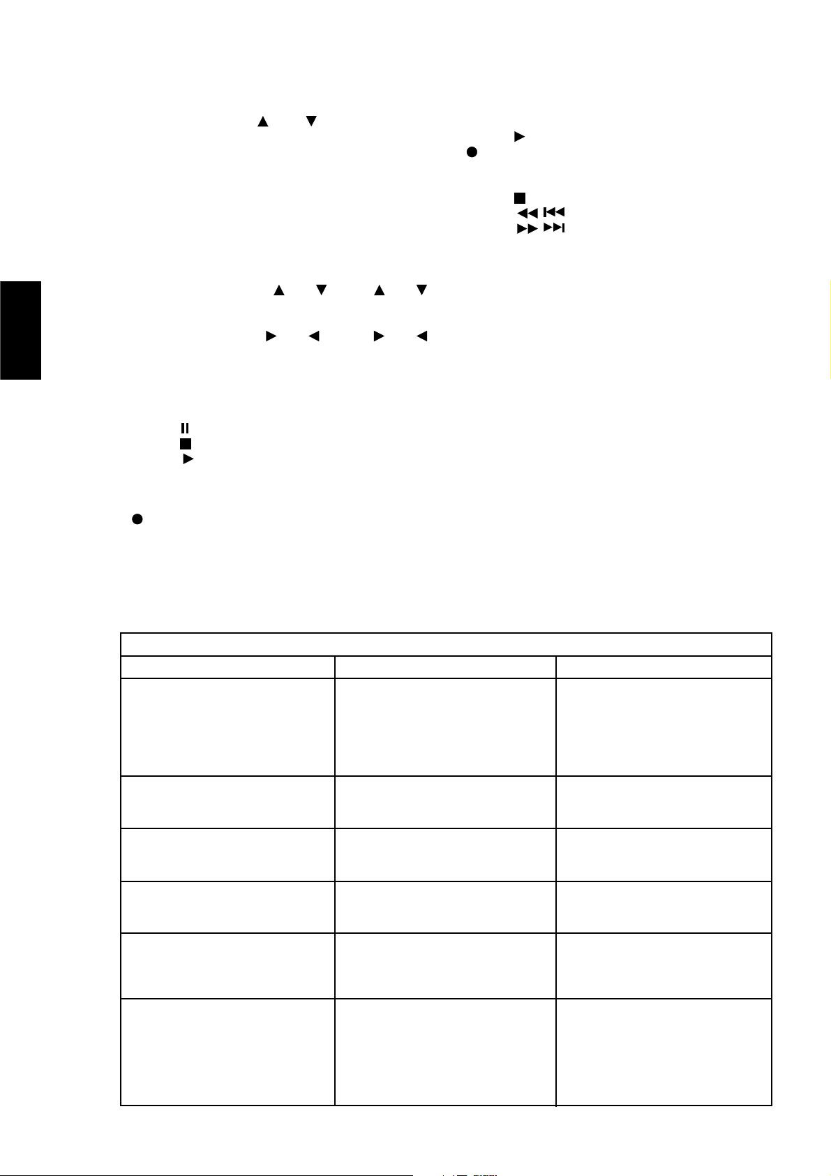
18
ENGLISH FRANÇAIS
DEUTSCH
ESPAÑOL
ITALIANO
PORTUGUÊS
SVENSKA
VOLUME GLOBAL [MASTER VOLUME]
Appuyez sur les boutons ou du VOLUME GÉNÉRAL
[MASTER VOLUME] pour augmenter ou diminuer le volume sonore,
respectivement. Relâchez le bouton dès que le niveau sonore souhaité a
été atteint. La Commande de Volume motorisée sur la face parlante
indiquera le niveau réglé. Les boutons de Volume Global [Master
Volume] n’affectent pas les enregistrements faits via les sorties de
magnétophone [Tape], mais affecteront tout de même le signal allant
vers les sorties de préamplification (Pre-Out 1 & 2).
COMMANDE DE TUNER
(à utiliser avec un Tuner NAD)
Les boutons d'ACCORDEMENT ou [TUNE ou ]
permettent de balayer les stations en remontant ou en descendant,
respectivement, les bandes AM et FM.
Les boutons de PRÉRÉGLAGE ou [PRESET ou ]
sélectionnent le numéro de station présélectionnée suivante ou
précédente, respectivement.
COMMANDE DE LECTEUR CD
(à utiliser avec un lecteur de CD/DVD NAD)
Le bouton met l'appareil en mode Pause
Le bouton met l'appareil en mode Arrêt [Stop]
Le bouton active le mode Lecture [Play] ou permute entre les
modes Lecture et Pause, ou active le mode Saut de Piste [Track Skip] ;
appuyez une fois sur ce bouton soit pour sauter à la piste suivante, soit
pour retourner au début de la piste en cours ou précédente.
provoque l'Ouverture / Fermeture du plateau de CD; appuyez une
fois pour ouvrir le plateau de CD et une deuxième fois pour refermer le
tiroir et commencer la lecture.
Lorsque le sélecteur MAGNÉTO/TUNER - CD [TAPE/TUNER - CD] est en
position MAGNÉTO/TUNER [TAPE/TUNER], les touches de défilement
envoient des commandes de magnétophone ; lorsqu'il est en position
CD, ces mêmes touches de défilement envoient des commandes de CD.
COMMANDE DE LA PLATINE A CASSETTES
(à utiliser avec les lecteur de cassettes simples NAD)
Le bouton active la Lecture en Avant.
Appuyez sur cette touche pour mettre la platine à cassettes en
mode enregistrement-pause.
Appuyez sur "Lecture" [Play] pour commencer l’enregistrement.
Le bouton arrête la Lecture" ou l’Enregistrement.
Les boutons activent le Rembobinage Rapide [Rewind]
Les boutons activent l'Avance Rapide [Fast Forward].
Lorsque le sélecteur MAGNÉTO/TUNER - CD [TAPE/TUNER - CD] est en
position MAGNÉTO/TUNER [TAPE/TUNER], les touches de défilement
envoient des commandes de magnétophone ; lorsqu'il est en position
CD, ces mêmes touches de défilement envoient des commandes de CD.
NOTES: La télécommande livrée avec le C 372 est de type universel NAD
et est conçue pour commander plusieurs modèles NAD. Certains
boutons de ce combiné ne fonctionnent pas car les fonctions concernées
ne sont pas supportées par le C 372. Les boutons de sélection d’entrée
Vidéo 2 et Vidéo 3 (dans la section N° 2) de la télécommande ne
fonctionnent pas dans le cas du C 372.
Les rayons de soleil directs ou un éclairage d’ambiance très lumineux
peuvent avoir une incidence sur la plage et l’angle de fonctionnement de
la télécommande.
DEPANNAGE
AUCUN SON • Câble secteur débranché, ou alimentation
coupée.
• Tape 1 Monitor est sélectionné
• Fonction "Silencieux" [Mute] actif .
• Les liaisons d'amplificateur Pre-out/Main-in ne
sont pas présentes à l'arrière
• Aucun haut-parleur sélectionné
• Vérifier si le cordon d'alimentation est branché
et que la prise murale est sous tension
• Désélectionner le Mode Tape 1 Monitor.
• Désactiver la fonction "Silencieux" [Mute].
• Assurer les liaisons
• Sélectionner les haut-parleurs appropriés (A
et/ou B)
Problème Cause Solution
PAS DE SON SUR UNE VOIE • Commande de balance non centrée.
• Haut-parleurs incorrectement branchés ou
détériorés.
• Câble d'entrée débranché ou détérioré.
• Centrer la commande de balance.
• Vérifier les branchements et les haut-parleurs.
• Vérifier les câbles et les branchements.
GRAVES FAIBLES / IMAGE STEREO DIFFUSE OU
INEXISTANTE
• Haut-parleurs câblés en déphasé.
• Le Mode Ponté est sélectionné alors que les
haut-parleurs sont connectés normalement
• Vérifier le branchement de tous les haut-parleurs
de la chaîne.
• Désactiver le Mode Ponté
LA TELECOMMANDE NE FONCTIONNE PAS • Piles usées ou incorrectement insérées.
• Fenêtre d'émission ou de réception IR obstruée.
• Le récepteur IR se trouve en plein soleil ou sous
un éclairage d'ambiance trop puissant
• Vérifier ou remplacer les piles.
• Retirer les obstructions.
• Eloigner l'appareil des rayons de soleil directs,
réduire la luminosité
LA LED D'ALIMENTATION / PROTECTION RESTE
ROUGE LORS DE LA MISE SOUS TENSION
• Court-circuit dans le câblage des haut-parleurs • Mettre l'amplificateur hors tension et vérifier le
branchement des câbles des deux haut-parleurs,
aussi bien sur le panneau arrière que sur les
haut-parleurs eux-mêmes, puis remettre
l'amplificateur sous tension.
LA LED D'ALIMENTATION / PROTECTION PASSE
AU ROUGE PENDANT L'UTILISATION
• L'amplificateur a surchauffé.
• L'impédance globale des haut-parleurs est trop
faible
• Mettre l'amplificateur hors tension. Vérifier que
les fentes d'aération sur le dessus et le dessous
de l'amplificateur sont dégagées de toute
obstruction. Une fois que l'amplificateur aura
refroidi, le remettre sous tension.
• Vérifier que l'impédance globale des hautparleurs n'est pas inférieure à 4 ohms.
• Vérifier qu'il n'y a aucun court-circuit au niveau
des câbles des haut-parleurs.
Page 19
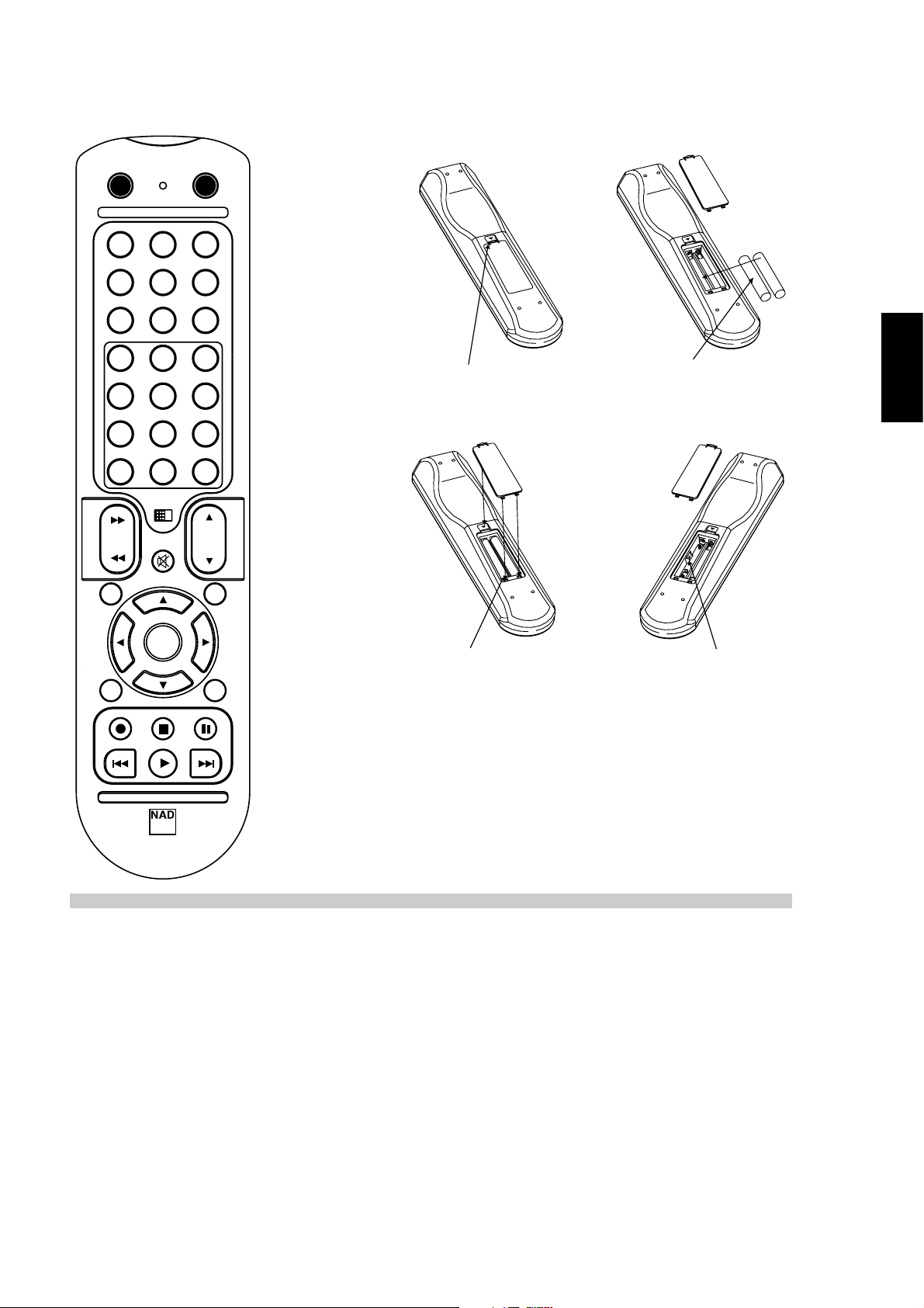
COMBINE DE TELECOMMANDE (FIGURE 3)
ON
ON
CD
DISC/PHONO
VIDEO 1
1
4
7
10
TAPE MON TAP E 2
VIDEO 2 VIDEO 3
TAPE /
TUNER
OFF
TUNER AUX
2
5
8
+10
0
CD
3
6
9
ENFONCEZ ET RELEVEZ LA LANGUETTE
POUR RETIRER LE COUVERCLE DU
COMPARTIMENT DES PILES
INSÉREZ LES PILES DANS LE
COMPARTIMENT. VÉRIFIEZ LA BONNE
MISE EN PLACE
ENGLISH
FRANÇAISDEUTSCHESPAÑOLITALIANO
VOL
PAUSE
SKIP
MONO
SPK
TUNE
REMETTEZ EN PLACE LE COUVERCLE
DU COMPARTIMENT DES PILES EN
B
ALIGNENT LES DEUX LANGUETTES
AVEC LES TROUS, PUIS EN LES Y
INSÉRANT.
APPUYEZ SUR LE COUVERCLE DU
COMPARTIMENT DES PILES POUR LE
METTRE UN PLACE (VOUS RESSENTIREZ
UN DÉCLIC)
TUNE
SCAN
DISP
SPK
A
OPEN/CLOSE
SKIP
MUTE
PRESET
ENTER
PRESET
STOP
PLAY
SR 5
CARACTÉRISTIQUES
SECTION AMPLIFICATEUR
Puissance de sortie en Mode Stéréo 2 x 170 W
(8 ohms dans les limites de la distorsion nominale)
Puissance dynamique IHF; 8 ohms 2 x 220 W
Puissance dynamique IHF; 4 ohms 2 x 340 W
Distorsion harmonique totale à la puissance nominale 0,02 %
Distorsion IM à la puissance nominale 0,003 %
Facteur d'amortissement 8 ohms > 150
Sensibilité et impédance de l'entrée à l'entrée 1.22 V / 20 k-ohms / 470 pF
Réponse de fréquence 20 à 20,000 Hz ± 0,3 dB
Rapport signal/bruit ; réf puissance nominale / 8 ohms (A-WTD) > 120 dB
Rapport signal/bruit ; réf 1 W / 8 ohms (A-WTD) > 100 dB
Télécommande Oui, SR 5
D
E
V
1
D
E
V2
DEV.1 & DEV.2
PORTUGUÊS
SVENSKA
Les caractéristiques de ce matériel peuvent être modifiées sans préavis.
Pour les dernières informations concernant votre C 372, et la dernière édition de la documentation et des caractéristiques détaillées,
connectez-vous à notre site web www.nadelectronics.com
19
Page 20

SCHNELLSTART
1 Schließen Sie die Lautsprecher A an den hinteren
Lautsprecherbuchsen und die Tonquellen an den entsprechenden
hinteren Eingangsbuchsen an.
2 Stecken Sie das Netzkabel zuerst in den C 372, dann in eine
Steckdose.
3 Drücken Sie zum Einschalten des NAD C 372 die Taste POWER.
4 Drücken Sie die erforderliche Eingangswahltaste.
HINWEISE ZUR AUFSTELLUNG
Der NAD C 372 sollte auf einer festen und ebenen Oberfläche
aufgestellt werden. Vermeiden Sie es, das Gerät direktem Sonnenlicht
oder Hitze und Feuchtigkeit auszusetzen. Achten Sie auf ausreichende
Luftzirkulation. Stellen Sie das Gerät nicht auf weiche Oberflächen wie
z. B. Teppiche, und nicht in abgeschlossene Bereiche wie Bücherregale
oder -schränke, wenn diese keine ausreichende Luftzirkulation
gewährleisten. Schalten Sie das Gerät aus, bevor Sie irgendwelche
Verbindungen herstellen.
Zur besseren Übersicht sind die gummiisolierten Anschlussbuchsen am
NAD C 372 farblich gekennzeichnet. Rot und weiß entsprechen dem
linken bzw. rechten Audiokanal, und gelb wird für die Systemsteuerung
(NAD Link) verwendet. Verwenden Sie für den Anschluss nur
hochwertige Leitungen und Buchsen, damit der NAD C 372 immer
optimal und zuverlässig arbeitet. Achten Sie außerdem darauf, dass
Anschlussleitungen und Buchsen frei von Beschädigungen sind und alle
Steckverbindungen fest sitzen.
Verwenden Sie für beste Leistung nur hochwertige Lautprecherkabel mit
mindestens 1,5 mm_ Querschnitt oder höher. Wird das Gerät längere
Zeit nicht benutzt, ziehen Sie den Netzstecker aus der Steckdose.
Sollte Wasser in den NAD C 372 eindringen, schalten Sie das Gerät
aus und ziehen den Netzstecker aus der Steckdose. Lassen Sie das
Gerät von einem qualifizierten Servicetechniker untersuchen, bevor
Sie es wieder verwenden. Nehmen Sie nicht den Gehäusedeckel
ab. Im Geräteinnern befinden sich keine vom Benutzer
reparierbaren Teile. Säubern Sie das Gerät mit einem trockenen
weichen Tuch. Befeuchten Sie das Tuch falls nötig leicht mit etwas
Seifenwasser. Verwenden Sie keine Lösungsmittel, die Benzol oder
andere Verdunstungsmittel enthalten.
RÜCKWANDANSCHLÜSSE (ABBILDUNG 1)
1. DISC-EINGANG (DISC INPUT)
CD-Player-Eingang II (DISC INPUT) Eingang für weitere LinepegelEingangssignale wie sie CD- und Minidisc-Player oder Vorverstärker für
Schalllplattenspieler liefern. Verbinden Sie diesen Eingang mit dem
linken und rechten Audioausgang des Zusatzgerätes über ein
zweifaches, gummiisoliertes Anschlusskabel.
2. CD-PLAYER-EINGANG (CD INPUT)
Eingang für einen CD-Player oder eine andere Linepegel-Signalquelle.
Verbinden Sie diesen Eingang mit dem linken und rechten CD-PlayerAudioausgang über ein zweifaches, gummiisoliertes Anschlusskabel.
Der NAD C 372 verarbeitet nur Analogsignale von einem CD-Player.
3. VIDEOEINGANG (VIDEO INPUT)
Eingang für das Audiosignal eines Stereo-Videorekorders (oder StereoTV/Satellitenempfängers) oder eine andere Linepegel-Tonsignalquelle.
Verbinden Sie diesen Eingang mit dem linken und rechten VCR- oder
SAT-Audioausgang über ein zweifaches, gummiisoliertes
Anschlusskabel. Hinweis: Nur Tonsignaleingang.
4. ZUSATZEINGANG (AUX INPUT)
Eingang für weitere Linepegel-Eingangssignale wie z. B. CD-Player.
Verbinden Sie diesen Eingang mit dem linken und rechten
Audioausgang des Zusatzgerätes über ein zweifaches, gummiisoliertes
Anschlusskabel.
5. TUNEREINGANG (TUNER INPUT)
Eingang für ein Radioempfangsgerät oder eine andere LinepegelSignalquelle. Verbinden Sie diesen Eingang mit dem linken und rechten
Audioausgang des Tuners über ein zweifaches, gummiisoliertes
Anschlusskabel.
6. TONBANDGERÄT-EIN-/AUSGANG 2 (TAPE 2 IN, OUT)
Anschlüsse für analoge Aufzeichnung und Wiedergabe eines beliebigen
Tonbandgerätes. Verbinden Sie für die Wiedergabe den linken und
rechten Audioausgang der Bandmaschine mit einem zweifachen,
gummiisolierten Anschlusskabel mit den Anschlüssen TAPE 2 IN
(Tonbandeingang 2). Für die Aufnahme verbinden Sie den linken und
rechten Audioeingang der Bandmaschine mit den Buchsen TAPE OUT 2
(Tonbandausgang 2).
7. TONBANDGERÄT-EIN-/AUSGANG 1 (TAPE 1 IN, OUT)
Anschlüsse für analoge Aufzeichnung und Wiedergabe eines beliebigen
zweiten Tonbandgerätes. Verbinden Sie zur Wiedergabe und
Bandüberwachung den linken und rechten Audioausgang der
Bandmaschine mit einem zweifachen, gummiisolierten Anschlusskabel
mit den Anschlüssen TAPE 1 IN (Tonbandeingang 1). Für die Aufnahme
verbinden Sie den linken und rechten Audioeingang der Bandmaschine
mit den Buchsen TAPE 1 OUT (Tonbandausgang 2).
8. VORVERSTÄRKERAUSGANG 1 (PRE-OUT 1)
Im Normalbetrieb ist der Ausgang PRE OUT 1 über die mitgelieferten
Verbindungskabel mit den Buchsen MAIN-In (Nr. 9) verbunden. Der
NAD C 372 ermöglicht den Anschluss mehrerer Leistungsverstärker.
Wenn Sie einen einzelnen, externen Stereo-Leistungsverstärker
verwenden, entfernen Sie die Verbindungen zu den Buchsen MAIN-IN.
Der interne Leistungsverstärker im C 372 wird dadurch getrennt.
Verbinden Sie die Buchsen PRE OUT 1 mit dem linken und rechten
Audioeingang des Leistungsverstärkers oder Prozessors über ein
zweifaches, gummiisoliertes Anschlusskabel.
Wenn Sie einen zusätzlichen Leistungsverstärker speziell für Bi-Amping
verwenden, schließen Sie den Leistungsverstärker mit der niedrigeren
Verstärkung an die Buchsen PRE OUT 1 an. Weitere Informationen dazu
finden Sie im Kapitel “Bi-Amping”.
HINWEISE: Schalten Sie den C 372 und andere angeschlossene externe
Leistungsverstärker immer aus, bevor Sie Verbindungen an den Buchsen
PRE-OUT 1, 2 und MAIN-IN herstellen oder trennen. Die Lautstärke- und
Klangeinstellungen des NAD C 372 beeinflussen die Ausgangssignale
PRE-OUT 1 & 2.
20
ENGLISH FRANÇAIS
DEUTSCH
ESPAÑOL
ITALIANO
PORTUGUÊS
SVENSKA
Page 21

9. MAIN IN
Anschluss für einen externen Vorverstärker oder Prozessor, wie z. B. ein
Surround-Sound-Dekoder. Normalerweise wird dieser Anschluss mit den
Buchsen PRE OUT 1 (Nr. 8) über das mitgelieferte Anschlusskabel
verbunden. Wenn Sie den NAD C 372 an externe Prozessoren oder
Vorverstärker anschließen möchten, entfernen Sie zuerst diese
Verbindungen. Verbinden Sie die Buchsen MAIN IN mit dem linken und
rechten Audioeingang des Vorverstärkers oder Prozessors über ein
zweifaches, gummiisoliertes Anschlusskabel.
HINWEISE: Schalten Sie den C 372 und andere angeschlossene externe
Leistungsverstärker immer aus, bevor Sie Verbindungen an den Buchsen
PRE-OUT 1, 2 und MAIN-IN herstellen oder trennen. Die Lautstärke- und
Klangeinstellungen des NAD C 372 beeinflussen die Ausgangssignale
PRE-OUT 1 & 2.
10. VORVERSTÄRKERAUSGANG 2 (PRE-OUT 2)
Über die Buchsen PRE OUT 2 kann ein weiterer Leistungsverstärker
angesteuert werden. Mit dem Einsteller VOLUME PRE OUT 2 (Nr. 11)
kann der Vorverstärker-Ausgangspegel zum Leistungsverstärker bis auf 12 dB reduziert werden. Ist dieser Einsteller in Maximalposition (Stellung
0 dB), ist der Ausgangspegel mit dem Pegel von PRE OUT 1 identisch.
Wenn Sie einen zusätzlichen Leistungsverstärker speziell für Bi-Amping
verwenden, sollten Sie den Leistungsverstärker mit der höheren
Verstärkung an die Buchsen PRE OUT 2 anschließen. Mit dem Einsteller
VOLUME PRE OUT 2 (Nr. 11) kann der Lautstärkepegel exakt mit dem
des an den Buchsen PRE OUT 1 angeschlossenen Leistungsverstärkers
abgestimmt werden. Weitere Informationen dazu finden Sie im Kapitel
“Bi-Amping”. Verbinden Sie die Buchsen PRE OUT 1 & 2 mit dem linken
und rechten Audioeingang des Leistungsverstärkers über ein
zweifaches, gummiisoliertes Anschlusskabel.
HINWEISE: Schalten Sie den C 372 und andere angeschlossene externe
Leistungsverstärker immer aus, bevor Sie Verbindungen an den Buchsen
PRE-OUT 1, 2 und MAIN-IN herstellen oder trennen. Die Lautstärke- und
Klangeinstellungen des NAD C 372 beeinflussen die Ausgangssignale
PRE-OUT 1 & 2.
11. LAUTSTÄRKE VORVERSTÄRKERAUSGANG 2
(VOLUME PRE OUT 2)
Der Einsteller VOLUME PRE OUT 2 ermöglicht die Anpassung des
Ausgangspegels an den Buchsen PRE OUT 2. Der Ausgangspegel kann
von 0 dB bis auf -12 dB reduziert werden. Ist dieser Einsteller in
Maximalposition (Stellung 0 dB), ist der Ausgangspegel mit dem Pegel
von PRE OUT 1 identisch. Weitere Informationen dazu finden Sie im
Kapitel “Bi-Amping”.
HINWEISE: Schalten Sie den C 372 und andere angeschlossene externe
Leistungsverstärker immer aus, bevor Sie Verbindungen an den Buchsen
PRE-OUT 1, 2 und MAIN-IN herstellen oder trennen. Die Lautstärke- und
Klangeinstellungen des NAD C 372 beeinflussen die Ausgangssignale
PRE-OUT 1 & 2.
12. BRIDGE-MODUS (BRÜCKENSCHALTUNG)
Durch Anschließen von zusätzlichen Leistungsverstärkern kann der NAD
C 372 als Teil eines noch stärkeren Stereo- oder Heimkinosystems
verwendet werden. Wenn mit der Endstufe des NAD C 372 ein
einzelner Lautsprecher angesteuert werden soll, können Sie mit dem
Bridge-Schalter die eingebauten linken und rechten Endstufen zu einem
Hochleistungskanal zusammenschalten.
Stellen Sie den Schalter BRIDGE MODE in die Position “Bridge” und
schließen Sie den Lautsprecher an den Klemmen “L +” und “R+” an.
Achten Sie dabei darauf, dass Sie “L+” mit der Klemme “+”, und “R+”
mit der Klemme “-” am Lautsprecher verbinden. Schließen Sie die
Tonquelle am linken Eingang MAIN-IN an.
In Brückenschaltung kann der NAD C 372 mit einem 8-OhmLautsprecher ca. 300 W erzeugen. In diesem Modus verhalten sich die
Endstufen so, als wäre die Impedanz der Lautsprecher halbiert worden.
Daher werden Lautsprecher mit niedriger Impedanz (weniger als 8 Ohm)
für die Brückenschaltung nicht empfohlen. Bei hohen Spitzen könnte
sonst der thermische Überlastschutz ansprechen und auslösen.
Im Bridge-Modus leuchtet die LED BRIDGE auf der Frontplatte (Abb. 2, Nr. 2).
HINWEISE: Schließen Sie bei aktiviertem Bridge-Modus keine Geräte an
die rechten Eingänge MAIN-IN (Nr. 9) an. Schalten Sie den C 372 und
andere angeschlossene externe Leistungsverstärker immer aus, bevor
Sie Verbindungen an den Buchsen PRE-OUT 1, 2 und MAIN-IN herstellen
oder trennen.
13. SOFT CLIPPING™
Die Belastung eines Verstärkers über seine nominale Ausgangsleistung
hinaus erzeugt bei lauten Passagen harte Verzerrungen. Dies wird durch
das Abschneiden oder “Hard Clipping” der Ausgangsspitzen
verursacht, für deren Wiedergabe der Verstärker nicht ausgelegt ist. In
solchen Fällen sorgt der Soft-Clipping-Schaltkreis von NAD für eine
weiche Ausgangssignalbegrenzung und minimiert bei Übersteuerung
des Verstärkers hörbare Verzerrungen.
Wenn Sie in der Regel bei niedriger Ausgangslautstärke Musik hören,
kann der Schalter für Soft Clipping™ in Stellung AUS (Off) bleiben.
Bevorzugen Sie jedoch eine hohe Ausgangslautstärke mit ausgereizter
Verstärkerleistung, schalten Sie das Soft Clipping™ über diesen Schalter
ein. Die LED Soft Clipping™ auf der Frontplatte zeigt den Soft-ClippingModus des Verstärkers an.
14. IR IN, OUT
Über den IR IN/OUT-Anschluß werden Befehle von anderen mit IR
IN/OUT-Anschlüssen ausgestatteten Geräten übertragen. Dadurch ist die
zentrale Steuerung eines ganzen Systems und der Grundfunktionen
anderer NAD-Komponenten (Tuner, CD-Player oder Kassettendecks), die
ebenfalls mit IR IN/OUT ausgestattet sind, über die Fernbedienung des
Verstärkers möglich. Damit dies mit solchen anderen Geräten
funktioniert, verbinden Sie IR OUT des C 372 mit IR IN des anderen
Gerätes. IR-Anschlüsse können in Reihe geschaltet werden, immer IN
auf OUT, so daß ein ganzes System über die Fernbedienung eines
Gerätes bedient werden kann.
HINWEISE: Es wird empfohlen, IR IN/OUT nicht zu verbinden, wenn
Geräte mit eigenem eingebautem Fernsteuerungsempfänger so nahe
beieinander stehen, daß eine direkte Sichtverbindung zur
Fernbedienung besteht. Im Zweifelsfall versuchen Sie zuerst die Geräte
ohne IR IN/OUT zu steuern. Reagiert das Gerät auf die Befehle der
Fernbedienung, ist eine Verbindung von IR IN/OUT nicht erforderlich.
Stellen Sie niemals eine Verbindung vom letzten Gerät zurück auf das
erste NAD-Gerät in der IR IN/OUT-Kette her. Vor dem Ein- oder
Ausstecken von IR IN/OUT alle Geräte vom Netz trennen.
21
ENGLISH
FRANÇAIS
DEUTSCHESPAÑOLITALIANO
PORTUGUÊS
SVENSKA
Page 22

15. 12-V-TRIGGERAUSGANG (12 V TRIGGER OUT)
Mit diesem Ausgang können andere Geräte wie z. B. Tuner,
Leistungsverstärker usw., die ihrerseits mit einem 12-V-Triggereingang
ausgestattet sind, ferngesteuert werden. Dabei kann es sich auch um
eine Wechselstrom-Netzleiste mit einem 12-V-Triggereingang handeln.
Der 12-V-Triggerausgang wird automatisch beim Einschalten des NAD
C 372 aus der AUS- oder STANDBY-Stellung aktiviert.
Soll über den C 372 eine externe Komponente vom Netzbetrieb in den
Bereitschaftsmodus geschaltet werden, verbinden Sie den 12-VTriggerausgang des C 372 mit dem Gleichspannungseingang dieser
Komponente. Dazu wird ein 3,5-mm-Standard-Miniaturstecker
(“Mono”) benötigt. Die Spitze ist spannungsführend oder die “+”Verbindung und der Kragen des Eingangssteckers bildet die 12-VTrigger- oder Ground-Verbindung (“-”).
HINWEISE: Überprüfen Sie die Daten des 12-V-Triggereingangs des
anderen Gerätes und stellen Sie sicher, dass diese mit dem 12-VTriggerausgang des C 372 kompatibel sind. NAD-Komponenten mit
einem 12-V-Triggereingang sind mit dem 12-V-Triggerausgang des
C 372 voll kompatibel. Die Spannung des 12-V-Triggerausgangs am
C 372 beträgt 12 V=. Der maximale Strom darf 200 mA nicht
überschreiten. Die Stromaufnahme der 12-V-Triggereingänge von NAD
ist in der Regel niedriger als 10 mA.
Bevor Sie Verbindungen zu irgendwelchen 12-V-Triggerein-/ oder ausgängen herstellen, achten Sie darauf, dass alle Geräte vom Netz
getrennt sind.
Das Nichtbeachten kann zu Schäden am C 372 oder an mit ihm
verbundenen Geräten führen. Wenn Sie noch Fragen zu Anschluss,
Installation und Betrieb des 12-V-Triggerausgangs haben, wenden Sie
sich bitte an Ihren NAD-Händler.
16. LAUTSPRECHER A + B (SPEAKERS A + SPEAKERS B)
Der NAD C 372 ist mit zwei Paaren von Lautsprecheranschlüssen
ausgestattet. Schließen Sie an den Buchsen SPEAKERS A die
Hauptlautsprecher an, und an den Buchsen SPEAKERS B ein zweites
Lautsprecherpaar, z. B. zuätzliche Lautsprecher, die sich in einem
anderen Raum befinden.
Verbinden Sie den rechten Lautsprecher mit den Klemmen “R +” (rechts
+) und “R -” (rechts -) und achten Sie dabei darauf, dass “R +” mit der
Klemme “+” des Lautsprechers und “R -” mit der Klemme “-” des
Lautsprechers verbunden ist. Schließen Sie den linken Lautsprecher an
den Klemmen “L +” (links +) und “L -” (links -) in der gleichen Weise an.
Im Bridge-Modus schließen Sie den Einzel-Lautsprecher an den
Klemmen “L +” und “R+” an. Achten Sie dabei darauf, dass Sie “L+”
mit der Klemme “+”, und “R+” mit der Klemme “-” am Lautsprecher
verbinden. Siehe auch Abschnitt “Bridge-Modus (Brückenschaltung)”
in diesem Kapitel (Nr. 12).
Verwenden Sie für den Anschluss von Lautsprechern am NAD C 372
immer schwere Litzenleitungen (1,5 mm oder höher).
An die Schraubanschlussklemmen mit hoher Strombelastbarkeit können
Leitungen mit Kabelschuhen oder Endhülsen und auch blanke
Leitungsenden angeschlossen werden.
BLANKE LEITUNGSENDEN UND ENDHÜLSEN
Blanke Leitungsenden und Endhülsen sollten in das Loch im
Gewindestift der Anschlussklemme eingeführt werden. Lösen Sie die
Lautsprecheranschluss-Kunststoffmutter bis das Loch im Gewindestift
freiliegt. Führen Sie die Endhülse oder das blanke Leitungsende in das
Loch ein und sichern Sie die Leitung durch festes Anziehen der
Kunststoffmutter. Achten Sie darauf, dass keine blanken Litzen von
Lautsprecherleitungen die Rückwand oder andere Anschlüsse berühren.
Stellen Sie sicher, dass nur ca. 1 cm blankes Kabel oder Stift und keine
losen Litzen vorhanden sind.
HINWEIS: Stellen Sie sicher, dass die Lautsprecher-Impedanz 4 Ohm oder
mehr beträgt, wenn nur ein Lautsprecherpaar angeschlossen wird. Beim
Anschluss von zwei Lautsprecherpaaren unbedingt darauf achten, dass die
Impedanz aller Lautsprecher 8 Ohm übersteigt. Im Bridge-Modus sollte die
Impedanz der Lautsprecher ebenfalls 8 Ohm oder mehr betragen.
17. GESCHALTETER NETZAUSGANG
(SWITCHED AC OUTLET)
An diesem Zusatzausgang kann das Netzkabel eines anderen
Stereogerätes eingesteckt werden. Geräte, die an diesem
Wechselspannungsausgang angeschlossen sind, werden über den
Schalter POWER auf der Frontplatte oder die Taste ON und STAND-BY
der Fernbedienung ein- und ausgeschaltet.
HINWEIS: Die Gesamtleistungsaufnahme aller an den Netzausgängen
angeschlossenen Geräten darf 100 Watt nicht überschreiten.
18. IEC-NETZANSCHLUSS (POWER)
Der NAD C 372 wird mit einem separaten Netzkabel geliefert. Bevor Sie
dieses Kabel mit einer spannungsführenden Netzsteckdose verbinden,
stellen Sie sicher, daß es zuerst fest mit der Netzeingangsbuchse des
C 372 verbunden ist. Entfernen Sie das Netzkabel immer zuerst von der
Netzsteckdose, bevor Sie es von der Netzeingangsbuchse des C 372
abziehen.
FRONTPLATTENELEMENTE (ABBILDUNG 2)
1. NETZSCHALTER EIN/AUS (POWER ON/OFF)
Drücken Sie die Taste POWER, um den Verstärker einzuschalten. Die
Netzanzeige (Nr. 2) über der Drucktaste POWER leuchtet gelb auf und zur
Signalisierung, dass der Verstärker für den normalen Betrieb bereit ist, kurz
danach grün. Erneutes Drücken des Schalters POWER schaltet das Gerät
vollständig AUS. Es reagiert dann nicht mehr auf die Fernbedienung.
EIN- UND AUS-TASTEN DER FERNBEDIENUNG (ABB. 3)
Der NAD C 372 die separaten Tasten ON und OFF, mit denen
Systemkomponenten besonders bequem „sychronisiert“ werden können,
d. h. alle Komponenten schalten in den Bereitschafts- oder Betriebsmodus,
wenn die Taste OFF bzw. ON gedrückt wird. So wird vermieden, dass
manche Geräte einschalten, wenn der Verstärker in den
Bereitschaftsmodus geschaltet wird. (Beachten Sie, dass die anderen
Komponenten ebenfalls in der Lage sein müssen, diese Ein-/Aus-Signale zu
verarbeiten). Schalten Sie mit der Taste ON das Gerät vom Bereitschafts- in
den Betriebsmodus; die Stand-By-Anzeige (Abb. 2, Nr. 2) wechselt kurz
danach von gelb nach grün, und die Anzeige für die zuletzt gewählte
Tonquelle leuchtet auf. Drücken Sie die Taste OFF, um das Gerät in den
Bereitschaftsmodus (STAND-BY) zu schalten. Die Breitschaftsanzeige
leuchtet gelb.
HINWEIS: Im Bereitschaftsmodus verbraucht der C 372 nur sehr wenig
Energie. Wir empfehlen aber trotzdem, das Gerät ganz auszuschalten,
wenn es für einige Tage nicht benutzt werden sollte. Das Gerät wird
durch Drücken auf die Drucktaste POWER auf der Frontplatte (Nr. 1)
ganz ausgeschaltet. Dabei verlöschen alle Leuchtanzeigen.
22
ENGLISH FRANÇAIS
DEUTSCH
ESPAÑOL
ITALIANO
PORTUGUÊS
SVENSKA
Page 23

23
ENGLISH
FRANÇAIS
DEUTSCHESPAÑOLITALIANO
PORTUGUÊS
SVENSKA
2. POWER / STAND-BY / PROTECTION (NETZ /
BEREITSCHAFTSMODUS- / SCHUTZSCHALTUNGSANZEIGE)
Nach dem Einschalten leuchtet die LED gelb für den
Bereitschaftsmodus. Wird eine der Eingangswahltasten gedrückt,
leuchtet die LED kurz rot und danach grün für Betrieb. In Fällen von zu
hoher Beanspruchung mit Überhitzung, bei extrem niedriger
Lautsprecher-Impedanz, Kurzschluß usw. aktiviert der Verstärker die
Schutzschaltung, die LED leuchtet rot und die Wiedergabe wird
abgeschaltet. Schalten Sie in einem solchen Fall den Verstärker aus,
warten bis er sich abgekühlt hat und/oder überprüfen die
Lautsprecherverbindungen und stellen Sie sicher, daß die LautsprecherGesamtimpedanz 4 Ohm nicht unterschreitet. Sobald die Ursache für
die Aktivierung der Schutzschaltung beseitigt ist, schalten Sie den
Verstärker wieder mit der Taste POWER ein.
Die folgende Abbildung veranschaulicht den Betrieb der
Bereitschaftsmodus-/Schutzschaltungsanzeige:
3. KOPFHÖRERBUCHSE (HEADPHONE)
Eine 6,3-mm-Stereo-Klinkenbuchse, an die alle gängigen Kopfhörer
mit beliebiger Impedanz angeschlossen werden können, ermöglicht
das Musikhören über Kopfhörer. Die Kopfhörerbuchse funktioniert
parallel zu den ausgewählten Lautsprechern. Wenn die Wiedergabe
ausschließlich über Kopfhörer erfolgen soll, deaktivieren Sie die
Lautsprecher A und/oder B (Nr. 4). Die Lautstärke- und Klangeinsteller
arbeiten dann für den Kopfhörerbetrieb. Um Kopfhörer mit anderen
Anschlusssteckern wie z. B. 3,5-mm-Klinkenstecker anzuschließen,
können entsprechende Adapter verwendet werden.
HINWEIS: Stellen Sie sicher, dass die Lautstärke auf ein Minimum eingestellt
ist (voll gegen den Uhrzeigersinn), bevor Sie Kopfhörer anschließen.
Musikhören bei sehr hoher Lautstärke kann das Gehör schädigen.
4. LAUTSPRECHER A, B (SPEAKERS A, B)
Die Tasten SPEAKERS A und B aktivieren oder deaktvieren die an den
Rückwandanschlüssen SPEAKERS A bzw. SPEAKERS B angeschlossenen
Lautsprecher. Drücken Sie A, um die an den Buchsen SPEAKERS A
angeschlossenen Lautsprecher ein- oder auszuschalten. Drücken Sie B,
um die an den Buchsen SPEAKERS B angeschlossenen Lautsprecher einoder auszuschalten. Die Anzeige direkt über den Tasten signalisiert den
Status der Lautsprecher A und B.
Wenn die Lautsprecher A und B aktiviert sind (beide Anzeigen über den
Tasten SPEAKERS A und B leuchten), werden beide Lautsprecherpaare
parallel vom Verstärkerausgang gespeist. Sind die Lautsprecher A und B
deaktiviert, ist die Wiedergabe beider Lautsprecherpaare abgeschaltet.
Diese Einstellung können Sie zum Hören über Kopfhörer (Nr. 3)
verwenden.
HINWEISE: Verringern Sie immer die Lautstärke, bevor Sie eines der
Lautsprechersysteme SPEAKERS A oder SPEAKERS B ein- oder
ausschalten.
Wenn Sie die Lautsprecher A und B gleichzeitig verwenden, stellen Sie
sicher, dass die Gesamtimpedanz der angeschlossenen Lautsprecher 8
Ohm übersteigt. Siehe Tabelle unten.
5. EINGANGSWAHLSCHALTER
Mit diesen Tasten wird der aktive Eingang für den NAD C 372 und das
Signal für Lautsprecher, Tonbandausgänge und die Buchsen PRE OUT
ausgewählt.
Die entsprechenden Tasten auf der Fernbedienung erfüllen dieselbe
Funktion, mit Ausnahme des Tunereingangs (siehe unten). Grüne
Leuchten über den Tasten zeigen an, welcher Eingang gerade
ausgewählt ist.
DISC Wählt eine an den DISC-Buchsen angeschlossene LinepegelTonquelle als aktive Eingangsquelle.
CD Wählt einen an den CD-Buchsen angeschlossenen CD-Player (oder
eine andere Linepegel-Tonquelle) als aktive Eingangsquelle.
VIDEO Wählt einen an den VIDEO-Buchsen angeschlossenen
Videorekorder (oder Stereo-TV-/Kabel-/Satellitenempfänger) als aktive
Eingangsquelle.
AUX Wählt eine an den AUX-Buchsen angeschlossene LinepegelTonquelle als aktive Eingangsquelle.
TUNER Wählt einen an den TUNER-Buchsen angeschlossenen
Empfänger (oder eine andere Linepegel-Tonquelle) als aktive
Eingangsquelle.
TAPE 2 Wählt TAPE 2 als aktiven Eingang.
TAPE 1 Monitor Wählt die Wiedergabe einer Bandmaschine oder die
Überwachung von Aufnahmen, die gerade über den Eingang TAPE 1
gemacht werden. Drücken Sie die Taste TAPE 1 einmal für eine
Aktivierung und ein weiteres Mal, um zur normalen Eingangseinstellung
zurückzukehren.
Die Bandüberwachungsfunktion TAPE 1 ändert nicht die gerade aktuelle
Eingangsauswahl. Ist z. B. CD der aktive Eingang, wenn TAPE 1 gedrückt
wird, bleibt das CD-Signal aktiv und wird immer noch an beide
Ausgangsbuchsen von TAPE 2 und TAPE 1 gesendet. Sie hören dann
allerdings aus den Lautsprechern den Ton von der an TAPE 1
angeschlossenen Bandmaschine. Neben der gelben Anzeige für TAPE 1
leuchtet ebenfalls die grüne Anzeige für den aktiven Eingang.
HINWEIS: Die mit dem C 372 gelieferte, universelle NADFernbedienung ist für die Steuerung von verschiedenen NAD-Modellen
geeignet. Da der C 372 jedoch nicht alle Funktionen dieser
Fernbedienung unterstützt, sind einige der Tasten ohne Funktion. Für
den C 372 sind die Eingangswahltasten VIDEO 2 und VIDEO 3 auf der
Fernbedienung ohne Funktion
6. INFRAROT-EMPFÄNGER DES
FERNBEDIENUNGSSIGNALS
Der Infrarotsensor hinter dem kreisförmigen Fenster empfängt die
Befehle von der Fernbedienung. Damit die Fernbedienung einwandfrei
funktioniert, darf die Sendestrecke zwischen der Fernbedienung und
dem Anzeigefenster nicht blockiert werden.
HINWEISE: Die Bereitschaftsmodus-/Schutzschaltungsanzeige blinkt,
wenn der Verstärker einen Befehl von der Fernbedienung erhält.
Beachten Sie, dass die LED-Anzeige nicht nur beim Empfang von
Befehlen für den C 372 sondern auch bei Befehlen für andere
Systemkomponenten blinkt. Direkte Sonneneinstrahlung oder eine sehr
helle oder fluoreszierende Umgebungsbeleuchtung kann den
Wirkungsbereich und Strahlungswinkel der Fernbedienung
beeinträchtigen.
7. ANZEIGE FÜR SOFT CLIPPING™
Die grüne Anzeige SOFT CLIPPING™ signalisiert den aktiven Soft
Clipping™-Modus. Weitere Informationen dazu finden Sie in
“Rückwandanschlüsse”, Abschnitt 13 “Soft Clipping™”.
Grün Gelb Rot
Normalbetrieb •
Bereitschaftsmodus •
Schutzschaltung •
Bridge-Modus (Brückenschaltung)
Stereo-Modus
Ein Lautsprecher 81 minimum Ein Lautsprecher 41 minimum
Zwei Lautsprecher 161 minimum Zwei Lautsprecher 81 minimum
Page 24

ENGLISH FRANÇAIS
DEUTSCH
ESPAÑOL
ITALIANO
PORTUGUÊS
SVENSKA
8. KLANGEINSTELLER FÜR TIEFEN & HÖHEN
(BASS & TREBLE)
Die Klangeinsteller BASS und TREBLE des NAD C 372 dienen der
Anpassung des System-Klangbildes. Die mit einer Einrastung
gekennzeichnete 12-Uhr-Position bewirkt ein flaches Klangbild, ohne
Verstärkung oder Abschwächung einzelner Frequenzen. Drehen Sie
die Einsteller im Uhrzeigersinn für eine Erhöhung, oder gegen den
Uhrzeigersinn für eine Verringerung der Bässe oder Höhen. Die
Klangeinsteller beeinflussen nicht die Aufnahmen, die über die TAPEAusgänge gemacht werden, wirken sich aber auf das
Vorverstärkerausgangssignal (PRE OUT 1 & 2) aus.
9. KLANGEINSTELLER AUS (TONE DEFEAT)
Der Schalter TONE DEFEAT schaltet die Klangregelung des NAD C 372
aus. Wenn Sie die Klangeinsteller normalerweise sowieso in der 12-UhrPosition lassen, ist es ratsam, das Klangregelsystem komplett durch
Drücken der Taste TONE DEFEAT abzuschalten. In der nichtgedrückten
Stellung ist das Klangregelsystem aktiv. Wenn Sie die Taste TONE
DEFEAT hineindrücken, werden die Klangeinsteller deaktiviert.
10. BALANCE
Der Einsteller BALANCE beeinflusst die relativen Pegel der linken und
rechten Lautsprecher. Die 12-Uhr-Position stellt die gleichen Pegel für den
linken und rechten Kanal ein. Eine Einrastung kennzeichnet diese Position.
Drehen des Einstellers im Uhrzeigersinn verschiebt die Balance nach
rechts. Drehen des Einstellers gegen den Uhrzeigersinn verschiebt die
Balance nach links. Der Einsteller BALANCE beeinflusst nicht die
Aufnahmen, die über die TAPE-Ausgänge gemacht werden, wirkt sich
aber auf das Vorverstärkerausgangssignal (PRE OUT 1 & 2) aus.
11. LAUTSTÄRKE (VOLUME)
Mit dem Einsteller VOLUME kann die Gesamtlautstärke der an die
Lautsprecher gesendeten Signale eingestellt werden. Er wird mit einem
Motor angetrieben und ist mit der Fernbedienung einstellbar. Der
Einsteller VOLUME beeinflusst nicht die Aufnahmen, die über die TAPEAusgänge gemacht werden, wirkt sich aber auf das
Vorverstärkerausgangssignal (PRE OUT 1 & 2) aus.
12. ANZEIGE BRIDGE MODE
Die Anzeige BRIDGE MODE leuchtet gelb, wenn der C 372 in den
Bridge-Modus (Brückenschaltung) geschaltet wird. Weitere
Informationen dazu finden Sie in “Rückwandanschlüsse”, Abschnitt 12
“Bridge-Modus”.
AUFNAHME
TONBANDAUFNAHMEN
Damit Tonbandaufnahmen durchgeführt werden können, wird das
Signal eines ausgewählten Eingangs auch direkt an die
Tonbandausgänge TAPE 2 oder TAPE 1 geführt.
ÜBERSPIELEN VON BAND ZU BAND
Zwischen zwei Bandmaschinen, die an den NAD C 372 angeschlossen
sind, kann Tonmaterial kopiert werden. Legen Sie das Quellenband in
das an TAPE 2, und das leere Band in das an TAPE 1 angeschlossene
Tonbandgerät ein. Wenn Sie jetzt den Eingang TAPE 2 wählen, können
Sie von TAPE 2 auf TAPE 1 überspielen und dabei das Signal vom
Originalband hören.
BI-AMPING (GETRENNTE LEISTUNGSVERSTÄRKER)
Manche Lautsprecher sind mit Anschlussklemmen für getrennte LF(niedrige Frequenzen) und HF- (hohe Frequenzen) Bereiche ausgestattet.
Solche Lautsprecher können dadurch im sogenannten “Bi-Amping”
betrieben werden, wobei jeweils ein Leistungsverstärker für den
niedrigen und hohen Frequenzbereich eingesetzt und die Klangqualität
des Gesamtsystems verbessert werden kann.
Um den Anschluss für Bi-Amping zu ermöglichen, bietet der NAD C 372
zwei Vorverstärkerausgänge (PRE OUT 1 & 2). Darüber hinaus kann der
Pegel von PRE OUT 2 gegenüber dem Pegel von PRE OUT 1 reduziert
werden. So ist eine einfache Anpassung von Leistungsverstärkern mit
unterschiedlichen Verstärkungsfaktoren möglich.
Bevor Sie mehr als einen Leistungsverstärker an den C 372 anschließen,
bestimmen Sie zuerst, welcher der beiden Verstärker die höhere
Verstärkung hat. Das kann ganz einfach durch Vergleichen der Lautstärke
der beiden Verstärker in einem identischen System festgestellt werden
(gleiche Lautstärkeeinstellung, gleiche Tonquelle und Lautsprecher). Der
Verstärker mit der höheren Lautstärke hat auch den höheren
Verstärkungsfaktor (wobei das nicht unbedingt auch derjenige mit der
höheren Ausgangsleistung sein muss). Schließen Sie den Verstärker mit
der höheren Verstärkung an PRE OUT 2 (Nr. 10) an und den anderen
Leistungsverstärker an den Buchsen PRE OUT 1 (Nr. 8). Reduzieren Sie in
maximaler Pegelposition (0 dB) mit dem Lautstärkeeinsteller VOLUME
PRE OUT 2 (Nr. 11) den Ausgangspegel von PRE OUT 2 so weit, bis der
Lautstärkepegel beider Leistungsverstärker genau übereinstimmt.
HINWEISE: Die Verstärkungen des Leistungsverstärkers NAD C 272 und
des im C 372 eingebauten Leistungsverstärkers sind identisch (die
Endstufen des C 272 und des C 372 sind auch annährend baugleich).
Wenn Sie den C 372 mit dem NAD C 272 für Bi-Amping kombinieren,
lassen Sie PRE-OUT 1 über die mitgelieferten Verbindungen an MAIN-IN
verbunden und schließen Sie den C 272 am Ausgang PRE-OUT 2 an.
Stellen Sie VOLUME PRE-OUT 2 in Maximalposition.
Wenn der C 372 die höhere Verstärkung hat, können die mitgelieferten
Verbindungen von PRE-OUT 1 zu MAIN-IN auch für die Verbindung von
PRE-OUT 2 zu MAIN-IN verwendet werden. Schalten Sie den C 372 und
externe Leistungsverstärker vor dem Anschließen oder Trennen von
Leitungen an den Buchsen PRE-OUT oder MAIN-IN immer aus.
POWERDRIVE
Mit unserem patentierten PowerDrive-Verstärkerschaltkreis, der den
verschiedenen Anforderungen von hohem Stromfluß und hoher
dynamischer Leistung gerecht wird, stärken wir weiter unseren Ruf für
erstaunlich effektive Leistung. Durch eine zweite
Hochspannungsschiene in unserem geregelten Hochstrom-Netzteil
erhalten wir einen „Overdrive“, der die Dauerleistung kurzzeitig fast
verdoppeln kann. Damit haben wir unseren renommierten, von NAD in
den 80ern und 90ern eingesetzten Power-Envelope-Schaltkreis noch
weiter entwickelt und verfeinert. PowerDrive unterscheidet sich von
Power Envelope darin, daß er noch bessere Verstärkerstabilität und die
Ansteuerbarkeit von niedrigen Impendanzen bietet. Das Ergebnis sind
weniger Verzerrungen bei der Ansteuerung von realen Lautsprechern
mit realem Programm-Material.
24
Page 25

25
ENGLISH
FRANÇAIS
DEUTSCHESPAÑOLITALIANO
PORTUGUÊS
SVENSKA
FERNBEDIENUNG (ABBILDUNG 3)
Mit der Fernbedienung können alle Hauptfunktionen des NAD C 372
ausgeführt werden. Sie bietet außerdem zusätzliche externe
Steuerungsmöglichkeiten für NAD Tuner, Kassettendecks und CDPlayer. Der Betrieb ist innerhalb einer Reichweite von 5 m möglich. Für
eine maximale Betriebsdauer werden vier Alkaline-Batterien AAA
(R03) empfohlen, die auf der Rückseite der Fernbedienung in das
Batteriefach eingelegt werden. Achten Sie beim Austausch von
Batterien darauf, daß diese entsprechend dem Schema auf dem
Batteriefach-boden richtig eingesetzt werden. Eine ausführliche
Beschreibung der einzelnen Fernbedienungsfunktionen finden Sie in
vorherigen Abschnitten dieser Bedienungsanleitung.
Die Bereitschaftsmodus-/Schutzschaltungsanzeige blinkt, wenn der
Verstärker einen Befehl von der Fernbedienung erhält. Beachten Sie,
daß die LED-Anzeige nicht nur beim Empfang von Befehlen für den
C 372 sondern auch bei Befehlen für andere Systemkomponenten
blinkt.
NETZ EIN/AUS (POWER ON/OFF)
Die NAD C 372 Fernbedienung hat separate ON- und OFF-Tasten. Das
ist besonders nützlich, um die Komponenten eines Systems zu
synchronisieren, d. h. alle Komponenten schalten in den Bereitschaftsoder Betriebsmodus, wenn die Taste OFF bzw. ON gedrückt wird. So
wird vermieden, daß manche Geräte einschalten, wenn der Verstärker
in den Bereitschaftsmodus geschaltet wird. (Beachten Sie, daß die
anderen Komponenten ebenfalls in der Lage sein müssen, diese Ein/Aus-Signale zu verarbeiten). Schalten Sie mit der Taste ON das Gerät
vom Bereitschafts- in den Betriebsmodus; die Stand-By-Anzeige
(Abb. 2, Nr. 2) wechselt kurz danach von gelb nach rot, dann nach
grün, und die Anzeige für den zuletzt gewählten Eingang leuchtet auf.
Drücken Sie die Taste OFF, um das Gerät in den Bereitschaftsmodus zu
schalten. Die Stand-By-Anzeige leuchtet gelb.
LAUTSPRECHER A, B (SPEAKERS A, B)
Diese Tasten erfüllen dieselbe Funktion wie die Tasten auf der
Frontplatte. Die Tasten SPEAKERS A und B aktivieren oder deaktvieren
die an den Rückwandanschlüssen SPEAKERS A bzw. SPEAKERS B
angeschlossenen Lautsprecher. Drücken Sie A, um die an den Buchsen
SPEAKERS A angeschlossenen Lautsprecher ein- oder auszuschalten.
Drücken Sie B, um die an den Buchsen SPEAKERS B angeschlossenen
Lautsprecher ein- oder auszuschalten. Die Anzeige direkt über den
Tasten signalisiert den Status der Lautsprecher A und B.
MUTE (STUMMSCHALTUNG)
Drücken Sie die Taste MUTE auf der Fernbedienung, um die
Klangwiedergabe der Lautsprecher oder Kopfhörer kurzzeitig
abzuschalten. Der MUTE-Modus wird durch Blinken der Anzeige des
aktiven Eingangs auf der Frontplatte angezeigt. Nochmaliges Drücken
der Taste MUTE schaltet die Klangwiedergabe wieder ein. MUTE
beeinflußt das Tonsignal am Vorverstärkerausgang (PRE OUT 1 & 2),
Aufnahmen über die TAPE-Ausgänge jedoch nicht.
EINGÄNGE (INPUTS)
Die Eingangswahltasten erfüllen dieselben Funktionen wie die
gleichnamigen Tasten auf der Geräte-Frontplatte.
LAUTSTÄRKE (MASTER VOLUME)
Drücken Sie die Tasten MASTER VOLUME oder , um die
Lautstärke zu erhöhen bzw. zu verringern. Lassen Sie die Taste los, wenn
die gewünschte Lautstärke erreicht ist. Der motorgesteuerte
Lautstärkeeinsteller auf der Frontplatte bewegt sich entsprechend der
eingestellten Lautstärke. Die Tasten MASTER VOLUME beeinflussen das
Tonsignal am Vorverstärkerausgang (PRE OUT 1 & 2), Aufnahmen über
die TAPE-Ausgänge jedoch nicht.
TUNER CONTROL
(in Verbindung mit NAD Tuner)
TUNE oder sucht die höheren bzw. tieferen
Senderfrequenzen für Mittelwelle (AM) und UKW (FM).
PRESET oder wählt eine niedrigere bzw. höhere
Sendervoreinstellungsnummer.
CD PLAYER CONTROL
(in Verbindung mit NAD CD/DVD-Player)
aktiviert Pause.
aktiviert Stop.
aktiviert die Wiedergabe oder schalten zwischen Wiedergabe und
Pause um oder aktiviert das Titelspringen. Einmal drücken, um auf den
nächsten Titel bzw. auf den Anfang des aktuellen oder vorherigen Titels
zu springen.
öffnet/schließt die CD-Schublade. Einmal drücken, um die CDSchublade zu öffen und erneut drücken, um sie wieder zu schließen und
mit der Wiedergabe zu beginnen.
Der Schalter TAPE/TUNER - CD aktiviert in Stellung TAPE/TUNER die
Transporttasten für ein Tonband und in der CD-Position für einen CDPlayer.
CASSETTE DECK CONTROL
(in Verbindung mit einfachen NAD-Kassettendecks)
aktiviert die Wiedergabe vorwärts.
aktiviert die Aufnahme-Pause-Funktion
Drücken Sie PLAY, um mit der Aufnahme zu beginnen.
stoppt die Wiedergabe oder Aufnahme.
aktiviert Zurückspulen.
aktiviert schnellen Vorlauf.
Der Schalter TAPE/TUNER - CD aktiviert in Stellung TAPE/TUNER die
Transporttasten für ein Tonband und in der CD-Position für einen CDPlayer.
HINWEISE: Die mit dem C 372 mitgelieferte NAD-UniversalFernbedienung ist für mehrere NAD-Modelle geeignet. Einige Tasten auf
dieser Fernbedienung werden vom C 372 nicht unterstützt und sind
daher ohne Funktion. Die Eingangswahltasten VIDEO 2 und VIDEO 3 (in
Abschnitt Nr. 2) auf der Fernbedienung bleiben für den C 372 ohne
Wirkung.
Direkte Sonneneinstrahlung oder sehr helle Umgebungsbeleuchtung
kann den Wirkungsbereich und Strahlungswinkel der Fernbedienung
beeinträchtigen.
Page 26

26
ENGLISH FRANÇAIS
DEUTSCH
ESPAÑOL
ITALIANO
PORTUGUÊS
SVENSKA
PROBLEMLÖSUNG
KEIN TON
• Netzkabel ausgesteckt oder Netzschalter nicht ON
• TAPE 1 MONITOR ausgewählt
• MUTE aktiv
• PRE-OUT/MAIN-IN nicht gebrückt
• Keine Lautsprecher aktiviert
• Netzkabel und Netzschalter überprüfen
• TAPE 1 MONITOR deaktivieren
• MUTE deaktivieren
• Brücken anbringen
• Gewünschte Lautsprecher aktivieren
(A und/oder B)
Problem Ursache Abhilfe
EIN KANAL OHNE TON • Balanceeinsteller nicht in Mittelstellung
• Lautsprecher nicht richtig angeschlossen oder
defekt.
• Eingangsanschluss- leitung ausgesteckt oder
defekt
• Balanceeinsteller in Mittelstellung bringen
• Lautsprecher und Anschlüsse überprüfen
• Anschlussleitungen und Verbindungen
überprüfen
SCHWACHE BÄSSE/ UNDEUTLICHES ODER KEIN
STEREOKLANGBILD
• Lautsprecheranschlüsse verpolt
• Aktiver Bridge-Modus bei normal
angeschlossenen Lautsprechern
• Alle Lautsprecheranschlüsse im System
überprüfen
• Bridge-Modus deaktivieren
FERNBEDIENUNG FUNKTIONIERT NICHT • Batterien leer oder falsch eingelegt
• IR-Sender- oder Empfängerfenster verdeckt
• IR-Empfänger in direktem Sonnenlicht oder sehr
hohe Umgebungs-beleuchtung
• Batterien überprüfen oder ersetzen
• Hindernis beseitigen
• Gerät nicht in direktem Sonnenlicht aufstellen,
Umgebungsbeleuchtung reduzieren
POWER/PROTECTION-LED BLEIBT NACH DEM
EINSCHALTEN ROT
• Kurzschluss in der Lautsprecherverkabelung • Verstärker ausschalten und Anschlüsse von
beiden Lautsprechern auf der
Verstärkerrückwand und an den Lautsprechern
überprüfen. Verstärker wieder einschalten
POWER/PROTECTION-LED LEUCHET WÄHREND
DES BETRIEBES ROT
• Verstärker überhitzt
• Gesamtimpedanz der Lautsprecher zu niedrig
• Verstärker ausschalten. Sicherstellen, dass
Lüftungsschlitze im Verstärker oben und unten
nicht blockiert sind. Nach Abkühlung des
Verstärkers wieder einschalten
• Sicherstellen, dass die Gesamtimpedanz der
Lautsprecher 4 Ohm nicht unterschreitet
• Lautsprecherkabel auf Kurzschluss überprüfen
TECHNISCHE DATEN
VERSTÄRKER
Ausgangsleistung Stereomodus 2 x 170W
(8 Ohm innerhalb Nennverzerrung)
IHF dynamische Leistung; 8 Ohm 2 x 220W
IHF dynamische Leistung; 4 Ohm 2 x 340W
Gesamtklirrfaktor bei Nennleistung 0,02%
IM-Verzerrung bei Nennleistung 0,003%
Dämpfungsfaktor 8 Ohm >150
Eingangsempfindlichkeit und Impedanz 1,22 V / 20kOhm/470 pF
Bandbreite 20 bis 20 000 Hz ±0,3dB
Rauschabstand bei Nennleistung / 8 Ohm (A-WTD) >120dB
Rauschabstand bei 1 W / 8 Ohm (A-WTD) >100dB
Fernbedienung ja, SR 5
Technische Änderungen vorbehalten.
Die neuesten Informationen über den C 372, aktualisierte Dokumentation und Funktionen finden Sie unter www.nadelectronics.com
Page 27

FERNBEDIENUNG (ABBILDUNG 3)
ON
ON
CD
DISC/PHONO
VIDEO 1
1
4
7
10
TAPE MON TAP E 2
VIDEO 2 VIDEO 3
TAPE /
TUNER
OFF
TUNER AUX
2
5
8
+10
0
CD
3
6
9
HINEINDRÜCKEN UND ZUM ABNEHMEN
DES BATTERIEFACHDECKELS LASCHE
ANHEBEN.
BATTERIEN IN DAS FACH EINLEGEN.
AUF EINWANDFREIEN SITZ DER
BATTERIEN ACHTEN.
ENGLISH
FRANÇAIS
DEUTSCHESPAÑOLITALIANO
TUNE
SCAN
DISP
SPK
A
OPEN/CLOSE
SKIP
MUTE
PRESET
ENTER
PRESET
STOP
PLAY
SR 5
VOL
PAUSE
SKIP
MONO
SPK
D
E
V
1
D
E
V2
TUNE
B
BATTERIEFACHDECKEL DURCH
AUSRICHTEN UND EINFÜHREN IN DIE
AUSSPARUNGEN WIEDER EINSETZEN.
BATTERIEFACHDECKEL
HINEINDRÜCKEN BIS ER MIT EINEM
HÖRBAREN KLICK SCHLIESST.
DEV.1 & DEV.2
PORTUGUÊS
SVENSKA
27
Page 28

SNELSTART
1 Sluit de luidsprekers aan op de Speaker A-aansluitingen en de
bronnen op de betreffende achterste ingangsstopcontacten.
2 Steek het netsnoer eerst in de C 372, en vervolgens in de
wandcontactdoos.
3 Druk op de POWER-toets om de NAD C 372 in te schakelen.
4 Druk op de gewenste ingangskeuzetoets.
INFORMATIE BETREFFENDE DE INSTALLATIE
Plaats uw NAD C 372 op een sterk, plat oppervlak. Plaats het apparaat
nooit in direct zonnelicht of dichtbij warmte- of vochtigheidsbronnen.
Zorg steeds dat het apparaat voldoende is geventileerd. Plaats het
apparaat nooit op een zacht oppervlak, zoals bijv. een tapijt. Plaats het
apparaat nooit in een gesloten omgeving, zoals bijv. een boekenkast of
een kast, daar dit de luchtstroming door de ventilatiegleuven kan
verhinderen. U dient zeker te stellen dat het apparaat is uitgeschakeld
alvorens eender welke aansluitingen te maken.
De RCA-stopcontacten van uw NAD C 372 zijn kleurgecodeerd om het
aansluiten te vergemakkelijken. De rode en witte stopcontacten zijn
respectievelijk voor Audio Rechts en Links.
Gebruik steeds hoogwaardige snoeren en stopcontacten om een
optimale prestatie en betrouwbaarheid te bewerkstelligen. Zorg ervoor
dat de snoeren en stopcontacten geenszins zijn beschadigd en dat alle
stekkers goed in de stopcontacten zijn bevestigd.
Om de allerbeste prestatie te bereiken, gebruik hoogwaardige 1,5 mm
dikke luidsprekersnoeren of nog dikkere. Indien u van plan bent het
apparaat redelijk lang niet te gebruiken, trek de stekker dan uit de
wandcontactdoos (wisselstroom).
Indien er water in uw NAD C 372 zou terechtkomen, schakel het
apparaat dan uit en trek de stekker uit de wandcontactdoos
(wisselstroom). Laat het apparaat nazien door een bevoegde
onderhoudstechnicus alvorens u het apparaat weer probeert te
gebruiken. Het dekpaneel niet van het apparaat verwijderen, daar
er geen onderdelen zijn die door de gebruiker kunnen worden
onderhouden of hersteld. Reinig het apparaat met een droge, zachte
doek. Indien nodig, maak de doek een beetje vochtig in een sopje.
Gebruik geen oplosmiddelen die benzeen of andere vluchtige middelen
bevatten.
ACHTERPANEELAANSLUITINGEN (AFBEELDING 1)
1. DISC INPUT [INGANG SCHIJF]
Dit is de ingang voor bijkomende ingangssignalen op lijnniveau, zoals
een cd-speler, een Mini Disc-speler of het uitgangssignaal van een
verhogende versterker voor een platendraaier. Gebruik een dubbel RCAnaar-RCA-snoer om de linkse en rechtse 'Audio-uitgangssignalen' van
het bijkomend apparaat aan deze ingang aan te sluiten.
2. CD INPUT [INGANG CD]
Dit is de ingang voor een cd-speler of een andere signaalbron op
lijnniveau. Gebruik een dubbel RCA-naar-RCA-snoer om de linkse en
rechtse 'Audio-uitgangssignalen' van de cd-speler aan deze ingang aan
te sluiten. De NAD C 372 kan enkel de analoge signalen van uw cdspeler aanvaarden.
3. VIDEO INPUT [INGANG VIDEO]
Dit is de ingang voor het audio-signaal van een stereo-videorecorder
(VCR) (of stereo-TV-/Satelliet-/Kabelreceiver) of een andere audio-bron
op lijnniveau. Gebruik dubbele RCA-naar-RCA-snoeren, om de linkse en
rechtse 'Audio-uitgangssignalen' van het apparaat aan deze ingangen
aan te sluiten. N.B.: Dit zijn slechts audio-ingangen.
4. AUX INPUT [INGANG AUX]
Dit is de ingang voor bijkomende ingangssignalen op lijnniveau, zoals
bijv. nog een andere cd-speler. Gebruik een dubbel RCA-naar-RCAsnoer om de linkse en rechtse 'Audio-uitgangssignalen' van het
bijkomend apparaat aan deze ingang aan te sluiten.
5. TUNER INPUT [INGANG TUNER]
Dit is de ingang voor een Tuner of een andere signaalbron op lijnniveau.
Gebruik een dubbel RCA-naar-RCA-snoer om de linkse en rechtse
'Audio-uitgangssignalen' van de Tuner aan deze ingang aan te sluiten.
6. TAPE 2 IN, OUT [CASSETTERECORDER 2 IN, UIT]
Dit zijn de aansluitingen voor het analoog opnemen en weergeven met
een audio-cassetterecorder van eender welk type. Gebruik dubbele
RCA-naar-RCA-snoeren om de linkse en rechtse 'Audiouitgangssignalen' van de cassetterecorder aan de TAPE 2 INstopcontacten te verbinden om de weergave te bewerkstelligen. Sluit
het linkse en rechtse 'Audio-ingangssignaal' van de cassetterecorder aan
op de TAPE 2 OUT-stopcontacten om op te nemen.
7. TAPE 1 IN, OUT [CASSETTERECORDER 1 IN, UIT]
Dit zijn de aansluitingen voor het analoog opnemen en weergeven met
een bijkomende audio-cassetterecorder van eender welk type. Gebruik
dubbele RCA-naar-RCA-snoeren om het linkse en rechtse ''Audiouitgangssignaal' van de cassetterecorder aan de TAPE 1 INstopcontacten aan te sluiten voor het weergeven en het monitoren van
de cassettes. Sluit het linkse en rechtse 'Audio-ingangssignaal' van de
cassetterecorder aan op de TAPE 1 OUT-stopcontacten om op te nemen.
8. PRE OUT 1
Bij normaal gebruik is de PRE OUT 1 aangesloten op de Main-Instopcontacten (Nr. 9) met behulp van de meegeleverde verbindingen.
Op de NAD C 372 is het mogelijk meerdere eindversterkers aan te
sluiten. Indien u één enkele externe stereo-eindversterker gebruikt, dient
u de verbindingen aan de Main-In-stopcontacten los te koppelen. De
interne eindversterker van de C 372 wordt daardoor afgesloten.
Gebruik een dubbel RCA-naar-RCA-snoer om de linkse en rechtse
'Audio-ingangssignalen' van de eindversterker aan de PRE OUT 1stopcontacten aan te sluiten.
Indien u speciaal voor "Bi-Amping" [gebruik van twee versterkers voor
LF en HF] een extra stereo-eindversterker gebruikt, gebruik dan de PRE
OUT 1-stopcontacten om de eindversterker met de minste versterking
van de twee aan te sluiten. Voor nadere inlichtingen, raadpleeg ook het
hoofdstuk "Bi- Amping" [gebruik van twee versterkers voor LF en HF].
N.B.: Schakel de C 372 en de aangesloten externe eindversterkers
steeds uit alvorens iets aan de stopcontacten PRE-OUT 1, 2 en MAIN-IN
aan te sluiten. De instellingen van de bedieningselementen van de NAD
C 372 voor de geluidssterkte [VOLUME] en de toon [TOON] beïnvloeden
de uitgangssignalen PRE-OUT 1&2.
28
ENGLISH FRANÇAIS
DEUTSCH
NEDERLANDS
ESPAÑOL
ITALIANO
PORTUGUÊS
SVENSKA
Page 29

9. MAIN IN
Dit zijn de aansluitingen voor een externe voorversterker of processor,
zoals bijv. een surround sound decodeerapparaat. Bij normaal gebruik
zijn deze aangesloten op de Pre-Out 1-stopcontacten (Nr. 8) met behulp
van de meegeleverde verbindingen. Verwijder eerst deze verbindingen
om uw NAD C 372 op een externe processor of voorversterker te
kunnen aansluiten. Gebruik een dubbel RCA-naar-RCA-snoer om de
linkse en rechtse 'Audio-uitgangssignalen' van de voorversterker of
processor aan te sluiten op de Main-In-stopcontacten.
N.B.: Schakel de C 372 en de aangesloten externe eindversterkers uit
alvorens iets aan de stopcontacten PRE-OUT 1, 2 en MAIN-IN aan te
sluiten.
De instellingen van de bedieningselementen voor de geluidssterkte
[VOLUME] en toon [TONE] van de NAD C 372 beïnvloeden de
uitgangssignalen PRE-OUT 1&2.
10. PRE OUT 2
U kunt de stopcontacten PRE OUT 2 gebruiken om een extra
eindversterker te sturen. U kunt het bedieningselement VOLUME PreOut 2 (Nr. 11) gebruiken om het uitgangsniveau van de voorversterker
naar de eindversterker tot -12dB te verminderen. Wanneer het
bedieningselement VOLUME Pre-Out 2 op maximum is ingesteld, zal
het uitgangsniveau hetzelfde zijn als dat van de stopcontacten PRE
OUT 1.
Indien u een paar eindversterkers speciaal voor "Bi-Amping" [gebruik
van twee versterkers voor LF en HF] gebruikt, gebruik dan de
stopcontacten PRE OUT 2 om de eindversterker met de grootste
versterking van de twee aan te sluiten. Door het bedieningselement
VOLUME PRE OUT 2 (Nr. 11) in te stellen, kan u de geluidssterkte precies
aanpassen aan de geluidssterkte van de eindversterker die is
aangesloten op de stopcontacten PRE OUT 1. Voor nadere inlichtingen,
raadpleeg het hoofdstuk "Bi-Amping" [gebruik van twee versterkers
voor LF en HF]. Gebruik een dubbel RCA-naar-RCA-snoer om de linkse
en rechtse 'Audio-ingang' van de eindversterker aan te sluiten op de
stopcontacten PRE OUT 1 & 2.
N.B.: Schakel de C 372 en de aangesloten externe eindversterkers
steeds uit alvorens iets aan te sluiten op, of af te sluiten van, de
stopcontacten PRE-OUT 1, 2 en MAIN-IN.
De instellingen van de bedieningselementen van de NAD C 372 voor de
geluidssterkte [VOLUME] en de toon [TONE] beïnvloeden de
uitgangssignalen PRE-OUT 1&2.
11. VOLUME PRE OUT 2 [GELUIDSSTERKTE PRE OUT 2]
Met behulp van het bedieningselement VOLUME Pre-Out 2 kunt u het
uitgangsniveau van de stopcontacten PRE OUT 2 instellen. Het
uitgangsniveau kan worden verlaagd van 0dB tot -12dB; wanneer het
op maximum is ingesteld, is het uitgangsniveau hetzelfde als dat van de
stopcontacten PRE OUT 1. Voor nadere inlichtingen, raadpleeg ook het
hoofdstuk "Bi-Amping" [Gebruik van twee versterkers voor LF en HF].
N.B.: Schakel de C 372 en de aangesloten externe eindversterkers
steeds uit alvorens iets aan te sluiten op, of af te sluiten van, de
stopcontacten PRE-OUT 1, 2 en MAIN-IN.
De instellingen van de bedieningselementen van de NAD C 372 voor de
geluidssterkte [VOLUME] en de toon [TONE] beïnvloeden de
uitgangssignalen PRE-OUT 1&2.
12. BRIDGE MODE [BRUGMODUS]
De NAD C 372 kan deel uitmaken van een stereo-installatie of
thuisbioscoop-installatie met een hoger vermogen, door extra
eindversterkers aan te sluiten. Wanneer het eindversterkerdeel in de
NAD C 372 wordt gebruikt om één enkele luidspreker te sturen, gebruik
dan de brugschakelaar 'Bridge' om de ingebouwde linkse en rechtse
eindversterkers te doen functioneren als een apparaat met hoog
vermogen en één enkel kanaal. Stel de brugmodusschakelaar [BRIDGE
MODE] in op de brugstand 'Bridge' en sluit de luidspreker aan op de
aansluitingen die zijn aangeduid met 'L +' en 'R+' en zorg ervoor dat de
'L+' is aangesloten op de aansluiting '+' van uw luidspreker en de 'R+'
is aangesloten op de aansluiting '-' van de luidspreker. Sluit de bron aan
op de linkse ingang van MAIN-IN.
In brugmodus [Bridge Mode] produceert de NAD C 372 ongeveer
300W in een luidspreker van 8 Ohm. In deze modus reageren de
versterkerdelen net alsof de impedantie van de luidspreker in de helft
was gesplitst. Luidsprekers met lage impedantie (minder dan 8 Ohm)
worden niet aanbevolen voor gebruik in de brugmodus [Bridge Mode],
daar zulke luidsprekers de thermische bescherming van de versterker
kunnen activeren wanneer er luid wordt gespeeld.
Het licht van de LED [Bridge] op het frontpaneel (Afb. 2; Nr. 3) gaat aan
wanneer de versterker zich in de brugmodus [Bridge mode] bevindt.
N.B.: Sluit niets aan op de rechtse ingang van MAIN-IN (Nr. 9) wanneer
u de [Bridge Mode] heeft geselecteerd. Schakel de C 372 en de
aangesloten externe eindversterkers steeds uit alvorens iets aan te
sluiten op, of af te sluiten van, de stopcontacten PRE-OUT 1, 2 en
MAIN–IN.
13. SOFT CLIPPING™ [GELUIDSPIEKEN AFKAPPEN]
Wanneer overdrive (overcapaciteit) van de versterker plaatsvindt, is er bij
zeer luide stukken een sterke geluidsvervorming hoorbaar. Dit wordt
veroorzaakt doordat de versterker de geluidspieken van geluiden die hij
niet kan weergeven, “afkapt”. Het soft clipping-circuit™ van NAD
beperkt het bereik van de uitgangssignalen om de hoorbare vervorming
te minimaliseren wanneer er overdrive van de versterker plaatsvindt.
Indien u gewoonlijk van een gemiddeld geluidsniveau gebruik maakt,
dan kan u de soft clipping-schakelaar in de stand Off (uit) laten staan.
Indien het waarschijnlijk is dat u een volume gebruikt dat hoger is dan
het versterkervermogen, schakel Soft Clipping dan in. Het licht van de
controlelamp Soft Clipping™ is aan wanneer de versterker zich in de
modus Soft Clipping bevindt.
29
ENGLISH
FRANÇAISDEUTSCH
NEDERLANDSESPAÑOL
ITALIANO
PORTUGUÊS
SVENSKA
Page 30

14. IR IN, OUT [IR IN, UIT]
De connector IR IN/OUT dient om opdrachten van andere apparaten die
met IR IN/OUT -connectoren zijn uitgerust door te geven. Daardoor kan
een hele installatie centraal worden bediend, en sommige van de
basisfuncties van andere NAD-apparatuur (bijv. tuner, cd-speler of
cassetterecorder) die ook zijn uitgerust met IR IN/OUT kunnen dus
worden bediend met behulp van de afstandsbediening van de
versterker. Om met zulke apparatuur te kunnen functioneren, sluit de IR
OUT van de C 372 aan op de IR IN van het ander apparaat. De IRconnectoren kunnen doorlopend als een ketting worden verbonden, IN
op OUT, zodat de hele installatie kan worden bediend met behulp van
de afstandsbediening van één apparaat.
N.B.: We raden aan de IR IN/OUT niet aan te sluiten indien deze
apparaten over hun eigen ingebouwde afstandsbedieningreceiver
beschikken en indien ze samen worden geplaatst, rechtstreeks in het
zicht van de afstandsbediening. Indien u hierover niet zeker bent,
probeer de apparaten dan eerst zonder IR IN/OUT te doen werken.
Indien het apparaat op de opdracht van de afstandsbediening reageert,
zal het niet noodzakelijk zijn de IR IN/OUT aan te sluiten.
Verbind het laatste apparaat nooit terug in een lus met het eerste NADapparaat in de IR IN/OUT-ketting. Sluit alle apparaten af van de
netvoeding alvorens de IR IN/OUT aan te sluiten of af te sluiten.
15. 12V TRIGGER OUT
Via de 12 V trigger-uitgang kan randapparatuur, zoals een tuner,
eindversterker, etc., op afstand worden in- of uitgeschakeld. Hiervoor
moet deze apparatuur wel zijn uitgerust met een 12 V trigger-ingang.
Dit kan ook een power strip voor lichtnet (wisselstroom) zijn met een 12
V trigger-ingang. De 12 V trigger-uitgang wordt geactiveerd zodra het
apparaat vanuit Standby of Uit wordt ingeschakeld.
Voor het overschakelen van Standby of het inschakelen van het externe
apparaat via de C 372 moet de 12 V trigger-uitgang van de C 372 op
de ingangsaansluiting (gelijkstroom) van het externe apparaat worden
aangesloten. Hiervoor is een 3,5 mm mini-aansluiting (mono) nodig. Het
punt van de 12 V-trigger is de aansluiting die onder stroom staat of de
+ aansluiting, de koker van de ingangsaansluiting is de 12V-trigger aansluiting of de aarding.
N.B.: Controleer de specificaties van de trigger-ingangsklem op de
andere apparaten om zeker te stellen dat ze compatibel zijn met de 12V
trigger-uitgang van de C 372.
NAD-apparaten die zijn uitgerust met 12V-ingang-triggers zijn geheel
compatibel met de 12V-trigger-uitgang van de C 372. De 12V triggeruitgangsspanning van de C 372 is 12V gelijkstroom. De totale maximale
stroom mag niet hoger zijn dan 100 mA. Normaal gezien gebruiken de
12V-ingang-triggers van NAD minder dan 10 mA stroom.
Alvorens iets aan te sluiten aan een 12V-trigger- ingang of -uitgang,
dient u zeker te stellen dat alle onderdelen van het lichtnet
(wisselstroom) zijn afgesloten.
Indien u de bovenstaande richtlijnen niet naleeft, kan dit schade
berokkenen aan de C 372 of de hierop aangesloten apparatuur. Indien
u onzeker bent van deze aansluitingen, de installatie of de werking van
de 12V- trigger-uitgang, gelieve contact op te nemen met uw NADverdeler.
16. SPEAKERS A + SPEAKERS B
[LUIDSPREKERS A + LUIDSPREKERS B]
De NAD C 372 is uitgerust met twee stellen luidsprekeraansluitingen.
Gebruik de aansluitingen Speakers A voor de hoofdluidsprekers en
gebruik de aansluitingen Speakers B voor een tweede paar, bijv.
verlengluidsprekers die zich in een andere ruimte bevinden.
Voor normaal gebruik, sluit de rechterluidspreker aan op de
aansluitingen die zijn aangeduid met 'R +' en 'R-'. Hierbij dient u zeker
te stellen dat 'R+' is aangesloten aan de '+'-aansluiting van uw
luidspreker en dat 'R-' is aangesloten aan de '-' -aansluiting van de
luidspreker. Sluit de aansluitingen aangeduid met 'L+' en 'L-' op
dezelfde wijze aan op de linkerluidspreker.
In de brugmodus [Bridge Mode], sluit de enkele luidspreker aan op de
aansluitingen die zijn aangeduid met 'R+' en 'L+'. Hierbij dient u zeker
te stellen dat 'R+' is aangesloten aan de '+'-aansluiting van uw
luidspreker en dat 'L+' is aangesloten aan de '-'aansluiting van de
luidspreker. Gelieve in dit hoofdstuk ook de rubriek "Brugmodus"
["Bridge Mode"] (Nr. 12) te lezen.
Gebruik steeds sterke gevlochten luidsprekerdraden (1,5 mm of dikker)
om de luidsprekers aan uw NAD C 372 aan te sluiten. U kunt de
hogestroomklemmen gebruiken als schroefklemmen voor kabels die
eindigen in de vorm van een kabelschoen of pen of voor kabels die
eindigen in aders zonder omhulling.
ONGEÏSOLEERDE DRADEN EN PENSTEKKERS
Ongeïsoleerde draden en penstekkers dient u in het gat van de klem te
steken. Hiertoe dient u de plastieken bus van de luidsprekerklem los te
schroeven zodat u het gat in de koker ziet. Steek de pen of het
ongeïsoleerde uiteinde van de draad in het gat en bevestig de draad
door de plastieken bus van de klem vast te schroeven.
Zorg ervoor dat de ongeïsoleerde draad van de luidsprekersnoeren niet
in contact komt met het achterpaneel of met een andere aansluiting.
Zorg ervoor dat er slechts 1 cm ongeïsoleerde draad of pen is en dat er
geen losse aders of luidsprekerdraden zijn.
N.B.: U dient zeker te stellen dat de impedantie van de luidspreker 4
Ohm is of meer wanneer u slechts één paar luidsprekers aansluit.
Verzeker er u van dat de luidsprekerimpedantie voor alle luidsprekers
meer dan 8 Ohm is wanneer u twee paar luidsprekers aansluit. In de
brugmodus [Bridge Mode] dient de luidsprekerimpedantie ook 8 Ohm
of meer te zijn.
17. SWITCHED AC OUTLET
[GESCHAKELD STOPCONTACT - WISSELSTROOM]
U kan het netsnoer (AC - wisselstroom) van een ander apparaat in dit
hulpstopcontact steken. Apparaten die op dit stopcontact zijn
aangesloten worden in- en uitgeschakeld d.m.v. de POWER-toets op het
frontpaneel of d.m.v. de toetsen ON en STAND-BY op de
afstandsbediening.
N.B.: Het totale energieverbruik van eender welk apparaat dat aan het
wisselstroomstopcontact [AC] is aangesloten mag 100 Watt niet
overschrijden.
30
ENGLISH FRANÇAIS
DEUTSCH
NEDERLANDS
ESPAÑOL
ITALIANO
PORTUGUÊS
SVENSKA
Page 31

18. IEC AC MAINS (POWER)
[INGANG WISSELSTROOMNETVOEDING]
De C 372 wordt geleverd met een afzonderlijk netsnoer (wisselstroom).
Alvorens het netsnoer in een wandcontactdoos die onder stroom staat
te steken, dient u zeker te stellen dat u het netsnoer eerst in het AC
Mains-stopcontact [wisselstroomnetvoeding] van de NAD C 372 steekt.
U dient ook zeker te stellen dat u de stekker van het netsnoer
(wisselstroom) altijd eerst uit de wandcontactdoos trekt, alvorens het
netsnoer uit het AC Mains-stopcontact [wisselstroomnetvoeding] van de
C 372 te verwijderen.
BEDIENINGSELEMENTEN OP HET FRONTPANEEL (AFB. 2)
1. POWER ON/OFF [NETVOEDING AAN / UIT]
Druk op de POWER-toets om de versterker in te schakelen. Het Standbylicht (Nr. 2) boven de Power-toets wordt oranje. Druk opnieuw op de
POWER-toets en dit schakelt het apparaat helemaal uit [OFF]. Het zal
niet op de afstandsbediening reageren.
AFSTANDSBEDIENING (AFBEELDING 3)
ON/OFF [TOETSEN AAN / UIT]
De afstandsbediening van de NAD C 372 beschikt over twee toetsen
voor het in- en uitschakelen [toetsen On en Off]. Dit kan uiterst nuttig
zijn om de verschillende apparaten van de installatie
"gesynchroniseerd" te houden. Op deze manier schakelen alle
apparaten over naar Standby wanneer u op de toets Uit [Off] drukt of
wanneer u inschakelt door op de toets Aan [On] te drukken, in plaats
van sommige apparaten in te schakelen [On] wanneer de versterker op
Standby wordt geschakeld. (Let wel dat de andere apparaten ook in
staat moeten zijn om op de individuele opdrachten Aan [On] en Uit [Off]
te kunnen reageren). Druk op de toets Aan [ON] om het apparaat van
Standby in te schakelen. Het Standby-licht (Afb. 2; Nr. 2) schakelt van
oranje naar rood, en vervolgens naar groen en het licht van de laatst
geselecteerde ingang zal knipperen en aangaan. Druk op de toets Uit
[OFF] om het apparaat in de Standby-modus te schakelen. Het Standbylicht wordt dan oranje.
N.B.: In Standby-modus verbruikt de C 372 slechts zeer weinig stroom.
Het is nochtans aanbevolen het apparaat volledig uit te schakelen
wanneer u van plan bent het meerdere dagen niet te gebruiken. Schakel
alles volledig uit door op de toets POWER te drukken op het frontpaneel
(Nr. 1). Alle lichten gaan dan uit.
2. CONTROLELAMP POWER/STANDBY/BESCHERMING
Wanneer u het apparaat inschakelt door op de toets POWER te drukken,
gaat de LED aan in oranje kleur en staat dus in de slaapstand [Standby].
Wanneer u vervolgens één van de ingangskeuzetoetsen indrukt, wordt de
LED momenteel rood EN vervolgens groen wat dus betekent dat het
apparaat is ingeschakeld [ON]. In geval van zwaar misbruik van de
versterker, bijv. oververhitting, een veel te lage luidsprekerimpedantie, een
kortsluiting enz., schakelen de Beschermingscircuits van de versterker zich
automatisch in. De LED schakelt zich dus van groen naar rood, en de
klank wordt gedempt. Schakel de versterker in dergelijk geval uit, en
wacht tot hij afkoelt en/of controleer de luidsprekeraansluitingen. Stel
daarbij zeker dat de algemene luidsprekerimpedantie niet lager dan 4
Ohm is. Zodra u weet waarom de beschermingscircuits werden
geactiveerd, druk opnieuw op de toets POWER om het apparaat weer in
de normale bedieningsmodus te zetten.
De onderstaande tabel illustreert de werking van de controlelamp
Slaapstand/Bescherming [Standby/Protection]:
3. KOPTELEFOONAANSLUITING
Het apparaat beschikt over een stereo-stopcontact van 6 mm voor het
luisteren met koptelefoon en het is geschikt voor traditionele
koptelefonen met eender welke impedantie. De koptelefoonaansluiting
werkt in parallel met de geselecteerde luidsprekers. Indien u enkel met
een koptelefoon wenst te luisteren, schakel de Luidsprekers A en/of B
(Nr. 4) dan uit.
De bedieningselementen voor de geluidssterkte [VOLUME], de toon
[TONE], en balance [BALANCE] blijven beschikbaar wanneer u met
koptelefoon luistert. Gebruik een passende adapter om een
koptelefoon met een andere soort stekker aan te sluiten, zoals bijv.
stereo-stekkers van 3,5 mm voor een walkman.
N.B.: U dient wel zeker te stellen dat het bedieningselement voor de
geluidssterkte [VOLUME] op minimum staat (volledig naar links
gedraaid) alvorens de koptelefoon aan- of af te sluiten. Het luisteren
met een te hoge geluidssterkte kan het gehoor beschadigen.
4. SPEAKERS A & B [LUIDSPREKERS A & B]
De toetsen Speakers A en B schakelen de luidsprekers die respectievelijk
aan de aansluitingen Speakers A en Speakers B op het achterpaneel zijn
aangesloten in of uit. Druk op A om de luidsprekers die aan de
aansluiting Speaker A zijn aangesloten in of uit te schakelen. Druk op B
om de luidsprekers die aan de aansluiting Speaker B zijn aangesloten in
of uit te schakelen. De controlelamp die zich boven de toetsen bevindt
geeft de stand van de luidsprekers A en B aan.
Indien de luidsprekers A en B beide zijn ingeschakeld (de beide
controlelampen boven de toetsen Speakers A en B zijn verlicht), wordt
het uitgangsvermogen van de versterker in parallel naar de twee
luidsprekers gevoerd. Indien de luidsprekers A en B zijn uitgeschakeld,
komt er geen klank uit de luidsprekers. U kan deze modus instellen om
via de koptelefoon te luisteren (Nr. 3).
N.B.: Verminder steeds de geluidssterkte [VOLUME] wanneer u
luidspreker A of luidspreker B in- of uitschakelt. En wanneer u de
luidsprekers A en B tegelijkertijd gebruikt, dient u zeker te stellen dat de
totale impedantie van de aangesloten luidsprekers meer dan 8 Ohm is.
Gelieve de onderstaande tabel te raadplegen:
31
ENGLISH
FRANÇAISDEUTSCH
NEDERLANDSESPAÑOL
ITALIANO
PORTUGUÊS
SVENSKA
Groen Oranje Rooad
Normale werking •
Slaapstand •
Bescherming •
Brugmodus [Bridge Mode] Stereo-modus
Eén luidspreker 8 1 min. Eén luidspreker 4 1 min.
Twee luidsprekers 16 1 min. Twee luidsprekers 8 1 min.
Page 32

5. INGANGSKEUZETOETSEN
Met behulp van deze toetsen kunt u de actieve ingang naar de NAD
C 372 selecteren en het signaal dat naar de luidsprekers wordt
gezonden, de Tape-uitgangen en de Pre-Out-stopcontacten. Deze
toetsen bevinden zich ook op de afstandsbediening, behalve de tuneringang; zie onderstaande gegevens. De groene controlelampen die zich
net boven elke toets bevinden tonen aan welke ingang er is
geselecteerd.
DISC Selecteert een bron op lijnniveau, die aan de DISC-stopcontacten
is aangesloten, als actieve ingang.
CD Selecteert de cd-speler (of een andere bron op lijnniveau), die aan
de CD-stopcontacten is aangesloten, als de actieve ingang.
VIDEO Selecteert het videoapparaat VCR (of stereo TV-/Satelliet/Kabelreceiver), dat aan de VIDEO-stopcontacten is aangesloten, als de
actieve ingang.
AUX Selecteert een bron op lijnniveau, die aan de AUX-stopcontacten
is aangesloten, als actieve ingang.
TUNER Selecteert de tuner (of een andere bron op lijnniveau), die aan
de Tuner-stopcontacten zijn aangesloten, als de actieve ingang.
TAPE 2 Selecteert Tape 2 als de actieve ingang.
TAPE 1 Monitor Selecteert de uitgang van een cassetterecorder voor
het spelen van cassettes of voor het monitoren van opnames die via de
Tape 1-stopcontacten worden opgenomen. Druk éénmaal op de toets
Tape 1 om deze te selecteren en druk nogmaals om terug over te gaan
naar de normaal geselecteerde ingang.
Tape 1 is een monitorfunctie voor cassettes die de huidige geselecteerde
ingang niet opheft. Bijv., indien de CD-speler de actieve ingang is
wanneer TAPE 1 wordt geselecteerd, dan blijft het CD-signaal
geselecteerd en wordt het zowel naar de TAPE 2, TAPE 1 OUTPUTstopcontacten gestuurd, maar het is de klank van de recorder die aan
Tape 1 is aangesloten die men via de luidsprekers hoort. Naast de oranje
controlelamp die aanduidt dat Tape 1 is ingeschakeld, blijft het licht van
de groene controlelamp voor de actieve ingang ook aan.
N.B.: De afstandsbediening die met de C 372 wordt meegeleverd is een
universeel type van NAD, dat speciaal is ontworpen om meerdere NADapparaten te bedienen. Sommige toetsen op deze afstandsbediening
werken niet daar de functies niet op de C 372 aanwezig zijn. De
keuzetoetsen Video 2 en Video 3 op de afstandsbediening werken niet
in het geval van de C 372.
6. INFRA-RODE AFSTANDSBEDIENING-OPDRACHTRECEIVER
De infrarode sensor, die zich achter dit cirkelvormig venster bevindt,
ontvangt opdrachten van de afstandsbediening. Het direct-zicht-pad
tussen de afstandsbediening en dit venster dient ongehinderd te zijn.
Indien er zich op dit pad hindernissen bevinden, is het eventueel
mogelijk dat de afstandsbediening niet werkt.
N.B.: Wanneer er een opdracht van de afstandsbediening wordt
ontvangen, knippert de controlelamp slaapstand/bescherming
[Standby/protection]. Let wel dat de controlelamp eventueel ook
knippert wanneer er opdrachten worden ontvangen die niet
noodzakelijk voor de C 372 maar voor andere apparaten van de
installatie zijn bestemd.
Rechtstreeks zonnelicht, en zeer hel of fluorescente
omgevingsverlichting kan het werkbereik en de hoek van de
afstandsbediening beïnvloeden.
7. CONTROLELAMP SOFT CLIPPING™
De groene controlelamp SOFT CLIPPING™ toont aan dat de modus Soft
Clipping™ is ingeschakeld. Voor nadere inlichtingen, gelieve ook het
hoofdstuk "Aansluitingen op het achterpaneel", rubriek 13; "Soft
Clipping™" te raadplegen.
8. BEDIENINGSELEMENTEN "BASS & TREBLE"
[LAGE EN HOGE TONEN]
De NAD C 372 beschikt over bedieningselementen voor lage en hoge
tonen [BASS & TREBLE] om de klank van uw installatie in te stellen en in
evenwicht te houden. De 12 uur-stand is 'plat' zonder dat de klank
wordt geboost of afgesneden en deze stand wordt aangeduid d.m.v.
een pal. Draai het bedieningselement naar rechts om de lage [Bass] of
hoge [Treble] tonen te verhogen. Draai het bedieningselement naar links
om de lage of hoge tonen te verlagen. De toonbedieningselementen
hebben geen invloed op de opnames die via de Tape-uitgangen worden
opgenomen maar hebben toch invloed op het signaal dat naar de
voorversterkeruitgangen wordt gevoerd (Pre-Out 1 & 2).
9. TONE DEFEAT [TOONOMLEIDING]
De toets TONE DEFEAT zorgt voor een omleiding rond het
toonregelingsdeel van de NAD C 372. Wanneer de
toonbedieningselementen normaal niet worden gebruikt en
eenvoudigweg in de 12 uur-stand blijven staan, raden we aan het
toonregelingsdeel d.m.v. deze toets volledig uit te schakelen. Wanneer
de toets niet is ingedrukt en dus 'buiten' is, blijven de
toonregelingscircuits actief. Door de toets TONE DEFEAT in te drukken,
bewerkstelligt u een omleiding rond het toonregelingsdeel.
10. BALANCE
Het bedieningselement BALANCE stelt de relatieve niveaus van de
linker- en rechterluidsprekers in. De 12 uur-stand zorgt voor een
evenwichtig niveau tussen de linker- en rechterkanalen. Deze stand
wordt met een pal aangeduid.
Door het bedieningselement naar rechts te draaien, verschuift het
evenwicht naar rechts. Door het bedieningselement naar links te
draaien, verschuift het evenwicht naar links. Het bedieningselement
BALANCE heeft geen effect op opnames die worden opgenomen via de
uitgangen Tape maar beïnvloedt toch het signaal dat naar de
voorversterkeruitgangen wordt gezonden (Pre-Out 1 & 2).
11. VOLUME [GELUIDSSTERKTE]
Met behulp van het bedieningselement VOLUME kan u de globale
geluidssterkte van de signalen die naar de luidsprekers worden gevoerd
instellen. Het wordt gestuurd door de motor en kan via de
afstandsbediening worden ingesteld. Het bedieningselement VOLUME
heeft geen effect op opnames die worden opgenomen via de uitgangen
Tape maar beïnvloedt toch het signaal dat naar de
voorversterkeruitgangen wordt gezonden (Pre-Out 1 &2).
12. CONTROLELAMP BRIDGE MODE [BRUGMODUS]
De controlelamp BRIDGE MODE gaat aan (oranje) wanneer de C 372 in
brugmodus wordt geschakeld. Voor nadere inlichtingen, gelieve ook het
hoofdstuk "Aansluitingen op het achterpaneel", rubriek 12,
"Brugmodus" te raadplegen.
OPNEMEN
EEN OPNAME MAKEN
Wanneer er eender welke bron is geselecteerd, wordt het signaal ook
rechtstreeks naar een cassetterecorder gezonden die is aangesloten aan
de uitgangen TAPE 2 of TAPE 1 om opnames te maken.
VAN CASSETTE NAAR CASSETTE TE COPIËREN
U kan copiëren tussen twee cassetterecorders die aan uw NAD C 372
zijn aangesloten. Steek de oorspronkelijke cassette in de recorder die
aan Tape 2 is aangesloten en de blanco cassette in de recorder die aan
Tape 1 is aangesloten. Door de ingang TAPE 2 te selecteren, kunt u nu
opnemen van Tape 2 naar Tape 1 en het signaal dat van de
oorspronkelijke cassette komt monitoren.
32
ENGLISH FRANÇAIS
DEUTSCH
NEDERLANDS
ESPAÑOL
ITALIANO
PORTUGUÊS
SVENSKA
Page 33

BI-AMPING
AFSTANDSBEDIENING (AFBEELDING 3)
De afstandsbediening bedient al de belangrijkste functies van de NAD
C 372 en omvat bijkomende bedieningselementen om de NAD Tunertoestellen, cassette- en cd-spelers op afstand te bedienen. De
afstandsbediening werkt op een afstand van 5 m. Om de
afstandsbediening zolang mogelijk te kunnen gebruiken, raden we aan
dat u alkalische batterijen gebruikt. Steek vier AAA-batterijen (R 03) in
het batterijvakje achterop de afstandsbediening. Wanneer u de
batterijen vervangt, let er dan op dat u ze correct heeft ingestoken,
volgens het schema onderaan in het batterijvakje. Gelieve de
bovenstaande rubrieken van deze handleiding te lezen voor een
volledige omschrijving van de verschillende functies.
Wanneer het apparaat een opdracht van de afstandsbediening
ontvangt, knippert de controlelamp Standby/Protection [Slaapstand /
Bescherming]. Let wel dat de controlelamp eventueel ook kan
knipperen wanneer er een opdracht wordt ontvangen die niet
noodzakelijk voor de C 372 maar voor andere apparaten van de
muziekinstallatie is bestemd.
POWER ON & OFF [NETVOEDING AAN & UIT]
De afstandsbediening van de NAD C 372 beschikt over gescheiden
toetsen On en Off voor het in- en uitschakelen. Dit kan bijzonder nuttig
zijn om de verschillende apparaten van een muziekinstallatie
gesynchroniseerd te houden. Volgens deze methode worden alle
apparaten op stand-by [slaapstand] geschakeld wanneer u op Off [Uit]
drukt en worden ze ingeschakeld wanneer u op On [Aan] drukt. Zo kan
u vermijden dat sommige apparaten worden ingeschakeld wanneer de
versterker op Stand-by [Slaapstand] wordt geschakeld. (Let wel dat de
andere apparaten ook op de gescheiden On [Aan] en Off [Uit]
opdrachten moeten kunnen reageren. ) Druk op de toets ON [Aan] om
het apparaat van Stand-by [Slaapstand] in te schakelen. De
controlelamp Stand-by [Slaapstand] (Fig. 2; Nr. 2) wordt eerst oranje en
dan rood, en vervolgens groen. De controlelamp voor de laatste
geselecteerde ingang zal knipperen en aangaan. Druk op de toets OFF
[Uit] om het apparaat in Stand-by-modus [Slaapstand] te schakelen. De
controlelamp voor Stand-by wordt oranje.
SPEAKERS A & B [LUIDSPREKERS A & B]
Deze toetsen hebben dezelfde functie als die op het frontpaneel. De
toetsen voor de luidsprekers A en B schakelen de luidsprekers, die
respectievelijk op de Speaker A- en Speaker B-aansluitingen op het
achterpaneel zijn aangesloten, in of uit.
Druk op A om de luidsprekers die aan de Speaker A-aansluiting is
aangesloten in- of uit te schakelen. Druk op B om de luidsprekers die
aan de Speaker B-aansluiting is aangesloten in- of uit te schakelen. De
controlelamp die zich net boven de toetsen bevindt toont de stand van
de luidsprekers A en B aan.
MUTE [DEMPEN]
Druk op de demptoets MUTE om de klank naar de luidsprekers en
koptelefoon tijdelijk te dempen. De dempmodus wordt aangetoond
door het knipperen van de controlelamp van de actieve ingang op het
frontpaneel. Druk opnieuw op MUTE om de klank te herstellen. De
dempmodus MUTE heeft geen effect op opnames die worden
opgenomen via de uitgangen Tape maar beïnvloedt toch het signaal dat
naar de voorversterkeruitgangen wordt gezonden (Pre-Out 1 &2).
INGANGSKEUZETOETSEN
De ingangskeuzetoetsen hebben dezelfde functie als de
overeenkomstige functies op het frontpaneel.
33
ENGLISH
FRANÇAISDEUTSCH
NEDERLANDSESPAÑOL
ITALIANO
PORTUGUÊS
SVENSKA
[GEBRUIK VAN TWEE VERSTERKERS VOOR LF EN HF]
Sommige luidsprekers hebben afzonderlijke aansluitingen voor de LF(Lage Frequentie) en HF- (Hoge Frequentie) delen van de luidspreker. Dit
maakt het mogelijk twee versterkers aan deze luidsprekers aan te sluiten
["Bi-Amping"], en dit wil zeggen dat er een afzonderlijke eindversterker
wordt gebruikt voor het LF- en het HF-deel. Dit procédé kan de
algemene klank verbeteren.
De NAD C 372 beschikt over twee paar voorversterkeruitgangen (PRE
OUT 1 & 2) om de aansluitingen voor "LF en HF" te vergemakkelijken.
Bovendien kan het niveau van de PRE OUT 2 worden verminderd t.o.v.
de PRE OUT 1 zodat u eindversterkers kan gebruiken met verschillende
versterking (versterkingsfactor).
Alvorens eindversterkers aan uw NAD C 372 aan te sluiten, dient u eerst
te beslissen welke eindversterker de meeste versterking biedt. Dit kunt
u makkelijk doen door de geluidssterkte van de eindversterkers van
éénzelfde installatie te vergelijken (zorg ervoor dat de geluidssterkte op
hetzelfde niveau is ingesteld; gebruik dezelfde bron en luidsprekers). De
versterker die het luidst speelt biedt de hoogste versterking (let wel dat
dit niet betekent dat dit de versterker is met het hoogste vermogen).
Sluit de versterker met de hoogste versterking aan op de PRE OUT 2(Nr.
10)-stopcontacten; en de andere eindversterker aan op de PRE OUT 1
(Nr. 8)-stopcontacten.
Vanaf de stand met het maximum niveau (0dB), gebruik het
bedieningselement VOLUME PRE OUT 2 (Nr. 11) om het uitgaand
niveau van de PRE OUT 2 te verminderen zodat beide eindversterkers op
hetzelfde niveau zijn ingesteld.
N.B.: De versterking van de NAD C 272-eindversterker is gelijk aan die
van de ingebouwde eindversterker van de C 372 (het eindversterkerdeel
van de C 272 en C 372 is bijna gelijk). Wanneer u combineert met de
NAD C 272 voor "Bi-Amping" (gebruik van twee versterkers voor LF en
HF), laat de PRE-OUT 1 dan aangesloten blijven, d.m.v. de meegeleverde
verbindingen, aan MAIN-IN. Sluit de C 272 aan op de uitgang PREOUT 2. Stel het bedieningselement VOLUME PRE-OUT 2 in op maximum.
De meegeleverde verbindingen om PRE-OUT 1 aan MAIN-IN aan te sluiten
kan u tevens ook gebruiken om PRE-OUT 2 aan MAIN-IN aan te sluiten,
in geval de eindversterker van de C 372 de hoogste versterking zou
bieden. Schakel de C 372 en de externe eindversterkers steeds uit
alvorens iets aan- of af te sluiten van de stopcontacten Pre-Out en MainIn.
POWERDRIVE
Om aan de uiteenlopende vereisten voor een hoge stroomsterkte en
hoog dynamisch vermogen te kunnen voldoen, wordt bij ons
gepatenteerde PowerDrive versterkercircuit voortgebouwd op onze
reputatie voor een uitermate effectief vermogen. Door een tweede
hoogspanningsrail aan onze goed afgeregelde voeding met hoge
stroomsterkte toe te voegen, krijgen we een “overdrive” waarmee het
continue vermogen op basis van een kortdurend dynamisch vermogen
bijna kan worden verdubbeld.
Dit is een verdere ontwikkeling en verfijning van ons bekende Power
Envelope circuit dat door NAD in de jaren 80 en 90 van de vorige eeuw
werd gebruikt. PowerDrive verschilt in zoverre van Power Envelope that
de stabiliteit van de versterker en het aandrijfvermogen met lage
impedantie wordt verbeterd, met als resultaat een minder sterke
vervorming bij het aansturen van echte luidsprekers met echt
programmamateriaal.
Page 34

MASTER VOLUME [HOOFDGELUIDSSTERKTE]
Druk op de toetsen MASTER VOLUME of om de
geluidssterkte respectievelijk te verhogen of te verminderen. Laat de
toets los wanneer u de gewenste geluidssterkte hebt bereikt. Het
gemotoriseerde bedieningselement voor de geluidssterkte op het
frontpaneel toont de geselecteerde geluidssterkte. De toetsen Master
Volume hebben geen effect op opnames die worden opgenomen via de
uitgangen Tape maar beïnvloeden toch het signaal dat naar de
voorversterkeruitgangen wordt gezonden (Pre-Out 1 &2).
BEDIENINGSELEMENT TUNER
(voor gebruik met NAD-Tuner)
TUNE (afstemmen) of scant respectievelijk de hogere of
lagere radiozenderfrequenties op zowel AM en FM.
PRESET (voorinstelling) of selecteert respectievelijk een
hogere of lagere voorinstelling van radiozender.
BEDIENINGSELEMENT CD-SPELER
(voor gebruik met NAD-CD/DVD-speler)
activeert Pause
activeert Stop
activeert Play [spelen] of schakelt tussen Play en Pause of activeert
het overslaan van een geluidsspoor. Druk er éénmaal op om
respectievelijk naar het volgende geluidsspoor over te gaan, of om terug
naar het begin van het huidige of een vroeger geluidsspoor te gaan.
activeert het openen en sluiten van de cd-lade. Druk er éénmaal
op om de cd-lade te openen en nogmaals om de cd-lade te sluiten en
de cd te spelen.
Met de toets TAPE/TUNER - CD kan u op de transporttoetsen cassetteopdrachten toepassen wanneer de toets op TAPE/TUNER is geschakeld,
en cd-opdrachten op de transporttoetsen toepassen wanneer de toets
op CD is geschakeld.
BEDIENINGSELEMENT CASSETTERECORDER
(voor gebruik met enkele NAD-cassetterecorders).
activeert het voorwaarts spelen
Druk op deze toets om het opnemen met cassetterecorder te
pauzeren.
Druk op Play om het opnemen te activeren.
Stopt het Spelen of het Opnemen.
Activeert het terugspoelen.
Activeert het voorwaarts spoelen.
Met de toets TAPE/TUNER - CD kan u op de transporttoetsen cassetteopdrachten toepassen wanneer de toets op TAPE/TUNER is geschakeld,
en op de transporttoetsen cd-opdrachten toepassen wanneer de toets
op CD is geschakeld.
N.B.: De afstandsbediening die met de C 372 wordt meegeleverd is een
universeel type van NAD, dat speciaal is ontworpen om meerdere NADapparaten te bedienen. Sommige toetsen op deze afstandsbediening
werken niet daar de functies niet op de C 372 aanwezig zijn. De
ingangskeuzetoetsen Video 2 en Video 3 (binnen het deel nr. 2) op de
afstandsbediening werken niet op de C 372.
Rechtstreeks zonnelicht, en een zeer helle of fluorescente
omgevingsverlichting kan het werkbereik en -hoek van de
afstandsbediening beïnvloeden.
34
ENGLISH FRANÇAIS
DEUTSCH
NEDERLANDS
ESPAÑOL
ITALIANO
PORTUGUÊS
SVENSKA
PROBLEMEN OPLOSSEN
GEEN GELUID • Netsnoer niet aangesloten of unit niet
ingeschakeld
• Tape 1 Monitor geselecteerd
• Mute ingeschakeld
• Achterste Pre Out/ Main in
versterkerverbindingen niet aangebracht
• Geen luidsprekers geselecteerd
• Controleer of netsnoer is ingestoken en unit is
ingeschakeld
• Schakel Tape 1 Monitor uit
• Schakel Mute uit
• Breng verbindingen aan
• Selecteer betreffende luidsprekers (A en/of B)
Probleem Oorzaak Oplossing
GEEN GELUID VIA EEN KANAAL • Balansregeling niet in midden
• Luidspreker niet correct aangesloten of
beschadigd
• Ingangskabel ontkoppeld of beschadigd
• Zet balansregeling in midden
• Controleer aansluitingen en luidsprekers
• Controleer kabels en aansluitingen
ZWAK LAAG/DIFFUUS OF GEEN STEREOBEELD • Luidspreker niet in fase aangesloten
• Overbruggingsmodus geselecteerd wanneer
luidsprekers normaal zijn aangesloten
• Controleer aansluitingen op alle luidsprekers
binnen systeem
• Schakel overbruggingsmodus uit
AFSTANDSBEDIENING WERKT NIET • Batterijen leeg of onjuist geplaatst
• Venster van IR-zender of -ontvanger niet vrij
• IR-ontvanger in direct zonlicht of zeer sterk
omgevingslicht
• Controleer en/of vervang batterijen
• Verwijder obstakel
• Haal unit uit direct zonlicht, verminder
hoeveelheid omgevingslicht
AAN-/UIT- / BEVEILIGINGS-LED BLIJFT ROOD NA
INSCHAKELEN
• Kortsluiting in luidsprekerkabels • Schakel versterker uit en controleer
kabelaansluitingen van beide luidsprekers op
achterpaneel van versterker en luidsprekers.
Schakel versterker in.
AAN-/UIT- / BEVEILIGINGSINDICATOR WORDT
ROOD TIJDENS NORMALE WERKING
• Versterker is oververhit geraakt
• Totale impedantie van luidsprekers te laag
• Schakel versterker uit. Controleer of de
ventilatiegleuven boven- en onderop versterker
niet zijn verstopt. Laat versterker afkoelen en
schakel hem in.
• Controleer of totale luidsprekerimpedantie niet
lager is dan 4 Ohm.
• Controleer luidsprekerkabels op kortsluitingen.
Page 35

AFSTANDSBEDIENING (AFBEELDING 3)
ON
ON
CD
DISC/PHONO
VIDEO 1
1
4
7
10
TAPE MON TAP E 2
VIDEO 2 VIDEO 3
TAPE /
TUNER
OFF
TUNER AUX
2
5
8
+10
0
CD
3
6
9
HET LIPJE INDRUKKEN EN OPHEFFEN
OM HET BATTERIJDEKSEL UIT DE
ZITTING TE VERWIJDEREN
STEEK DE BATTERIJEN IN HET
BATTERIJVAKJE. ZORG ERVOOR DAT U
DE BATTERIJEN CORRECT IN HET
BATTERIJVAKJE STEEKT.
ENGLISH
FRANÇAISDEUTSCH
PAUSE
SKIP
VOL
MONO
SPK
TUNE
HET BATTERIJDEKSEL TERUG
AANBRENGEN DOOR DE TWEE LIPJES
B
UIT TE LIJNEN EN IN DE GATEN AAN TE
BRENGEN. DRUK HET BATTERIJDEKSEL
TERUG OP ZIJN PLAATS TOTDAT HET
VASTKLIKT.
TUNE
SCAN
DISP
SPK
A
OPEN/CLOSE
SKIP
MUTE
PRESET
ENTER
PRESET
STOP
PLAY
SR 5
TECHNISCHE GEGEVENS
VERSTERKERDEEL
Uitgaand vermogen stereo-modus 2 x 170W
(8 Ohm binnen nominale vervorming)
IHF-dynamisch vermogen; 8 Ohm 2 x 220W
IHF-dynamisch vermogen; 4 Ohm 2 x 340W
Totale harmonische vervorming bij nominaal vermogen 0,02%
IM-vervorming bij nominaal vermogen 0,003%
Dempingsfactor 8 Ohm >150
Ingangsgevoeligheid en impedantie 1,22 V / 20kOhm/470 pF
Frequentieweergave 20 tot 20.000 Hz ±0,3dB
Signaal- / ruisverhouding; ref. nominaal vermogen / 8 Ohm (A-WTD) >120dB
Signaal- / ruisverhouding; ref. 1W / 8 Ohm (A-WTD) >100dB
Afstandsbediening Ja, SR 5
D
E
V
1
D
E
V2
DEV.1 & DEV.2
NEDERLANDSESPAÑOL
ITALIANO
PORTUGUÊS
SVENSKA
De technische kenmerken kunnen zonder voorafgaande kennisgeving worden gewijzigd.
Voor bijgewerkte documentatie en kenmerken, en de nieuwste informatie over uw C 372, kunt u terecht op www.nadelectronics.com.
35
Page 36

COMIENZO RAPIDO
1 Conecte los altavoces a las tomas de Speaker A (altavoz) y fuentes
traseras con las tomas de entrada traseras pertinentes.
2 En primer lugar, conecte el cordón de alimentación CA en el C 372
y luego en la toma de la pared.
3 Pulse el pulsador POWER para poner en On el NAD C 372.
4 Pulse el selector de entrada requerido.
NOTAS SOBRE LA INSTALACION
Su NAD C 372 debe colocarse sobre una superficie firme y nivelada.
Evite colocar el equipo a la luz directa del sol o cerca de calor o
humedad. Deje una ventilación adecuada. No coloque el equipo sobre
una superficie blanda como una alfombra. No lo coloque en un área
cerrada, como una estantería o armario, que impida el paso del aire
por las ranuras de ventilación. Asegure que el equipo esté
desconectado antes de hacer cualquier conexión.
Las tomas RCA de su NAD C 372 tienen códigos de color para mayor
comodidad. El rojo y el blanco son audio de Derecha e Izquierda
respectivamente, y el amarillo es para la NAD Link (conexión NAD). Use
conductores y tomas de alta calidad para rendimiento y fiabilidad
óptimos. Asegure que los conductores y tomas de enchufe no estén
dañados en modo alguno y que las tomas de enchufe estén enchufadas
firmemente hasta el fondo.
Para mejor rendimiento, use conductores de altavoz de calidad de
calibre 16 (1,5 mm) de espesor o más. Si el equipo no va a usarse
durante algún tiempo, desconecte el enchufe de la toma de CA.
Si penetra agua en su NAD C 372, cierre la alimentación eléctrica al
equipo y quite el enchufe de la toma de CA. Haga que inspeccione el
equipo un técnico de servicio cualificado antes intentar usarlo otra vez. No
quite la cubierta, no hay piezas en el interior que puedan ser
objeto de servicio por el usuario. Use un paño suave y seco para
limpiar el equipo. Si es necesario, humedezca un poco el paño con agua
jabonosa. No use soluciones que contengan benzol ni otros agentes
volátiles.
CONEXIONES DEL PANEL TRASERO (VEA LA FIGURA 1)
1. DISC INPUT (ENTRADA DE DISCO)
Entrada para señales de entrada de nivel de línea adicional como CD,
tocadiscos Mini Disc o la señal de salida de un amplificador de realce
para un tocadiscos. Use un conductor doble RCA-a-RCA para conectar
las ‘Salidas de Audio’ de derecha e izquierda de los equipos auxiliares a
esta entrada.
2. CD INPUT (ENTRADA DE CD)
Entrada para una fuente de señal de CD u otra señal de nivel de línea.
Use un conductor doble RCA-a-RCA para conectar las ‘Audio Output’
de izquierda y derecha del tocadiscos de CD a esta entrada. El NAD
C 372 acepta únicamente señales analógicas de su tocadiscos de CD.
3. VIDEO INPUT (ENTRADA DE VÍDEO)
Entrada para la señal de audio procedente de una cámara de grabación
de vídeo VCR estéreo (o receptor estéreo de TV/Satélite/Cable) u otra
fuente de audio de nivel de línea. Usando conductores dobles RCA-aRCA, conecte la ‘Salida de Audio’ de izquierda y derecha del equipo a
estas entradas. Nota: Estas son entradas de audio únicamente.
4. AUX INPUT (ENTRADA AUXILIAR)
Entrada para señales de entrada de nivel de línea adicional como otro
tocadiscos CD. Use un conductor doble RCA-a-RCA para conectar las
‘Salidas de Audio’ de derecha e izquierda de los equipos auxiliares a esta
entrada.
5. TUNER INPUT (ENTRADA DE SINTONIZADOR)
Entrada para un Sintonizador u otra fuente de seña de nivel de línea.
Use un conductor doble RCA-a-RCA para conectar las ‘Salidas de
Audio’ izquierda y derecha del Sintonizador a esta entrada.
6. TAPE 2 IN, OUT (ENTRADA, SALIDA DE CINTA 2)
Conexiones para grabación y escucha analógicas para una grabadora
de cinta de audio de cualquier tipo. Usando conductores dobles RCAa-RCA conecte la ‘Salida de Audio’ de izquierda y derecha de la
máquina de cintas a las tomas TAPE 2 IN para escuchar. Conecte la
‘Entrada de Audio’ de izquierda y derecha de la máquina de cintas a las
tomas TAPE 2 OUT para grabar.
7. TAPE 1 IN, OUT (ENTRADA, SALIDA DE CINTA 1)
Conexiones para grabación y escucha analógicas para una grabadora de
cinta de audio secundaria de cualquier tipo. Usando conductores dobles
RCA-a-RCA, conecte la ‘Salida de Audio’ de izquierda y derecha de la
máquina de cintas a las tomas TAPE 1 IN para escucha y control de
cintas. Conecte la ‘Entrada de Audio’ de izquierda y derecha de la
máquina de cintas a las tomas TAPE 1 OUT para grabar.
8. PRE-OUT 1 (SALIDA PRE 1)
En uso normal la PRE-OUT 1 está conectada a las tomas de Main-In
(entrada de alimentación principal) (No. 9). El NAD C 372 permite la
conexión de amplificadores múltiples de potencia. Si usa usted un
amplificador de potencia estéreo externo individual, desconecte las
conexiones con los enchufes Main-In. Ahora queda desconectado el
amplificador de potencia interno del C 372. Use un conductor doble
RCA-a-RCA para conectar la ‘Entrada de Audio’ de izquierda y derecha
del amplificador de potencia con las tomas PRE-OUT 1.
Si está usted usando un amplificador de potencia estéreo adicional
específicamente para Bi-Amping (biamplificación); use los enchufes PREOUT 1 para conectar el amplificador de potencia con la ganancia más
baja del par. Vea también el capítulo “Bi-Amping” para más
información.
NOTAS: Ponga siempre el C 372 y los amplificadores de potencia
externos asociados en Off antes de conectar o desconectar cualquier
cosa a los enchufes PRE-OUT 1, 2 y MAIN-IN. Las señales de salida PREOUT 1 & 2 quedarán afectadas por los ajustes de control de volumen y
tono del NAD C 372.
9. MAIN-IN
Conexiones para un preamplificador o procesador externo, como un
descodificador de entorno-sonido. En el uso normal deben conectarse a
las tomas Pre-Out 1(No. 8) con las conexiones provistas. Para conectar
su NAD C 372 a secciones de procesador o preamplificador externo
quite primero estas conexiones. Use un conductor doble RCA-a-RCA
para conectar con la ‘Salida de Audio’ de izquierda y derecha del
preamplificador o procesador con las tomas Main-In.
NOTAS: Ponga siempre el C 372 y los amplificadores de potencia
externos asociados en Off antes de conectar o desconectar cualquier
cosa a los enchufes PRE-OUT 1, 2 y MAIN-IN. Las señales de salida PREOUT 1 & 2 quedarán afectadas por los ajustes de control de volumen y
tono del NAD C 372.
36
ENGLISH FRANÇAIS
DEUTSCH
ESPAÑOL
ITALIANO
PORTUGUÊS
SVENSKA
Page 37

10. PRE-OUT 2
Los enchufes de PRE-OUT 2 pueden usarse para excitar un amplificador
de potencia adicional. El control de VOLUME Pre-Out 2 (No. 11) se
puede usar para reducir el nivel de salida del preamplificador al
amplificador de potencia en hasta -12dB. Con el control de VOLUME
Pre-Out 2 ajustado en la posición máxima (posición de 0dB), el nivel de
salida será idéntico al nivel de los enchufes PRE-OUT 1.
Si está usted usando un par de amplificadores de potencia
específicamente para Bi-Amping, use los enchufes PRE-OUT 2 para
conectar el amplificador de potencia con la ganancia más alta del par.
Ajustando el control VOLUME PRE-OUT 2 (No. 11) puede hacerse
coincidir exactamente el volumen con el del amplificador de potencia
conectado a los enchufes PRE-OUT 1. Vea también el capítulo “BiAmping” para más información. Use un conductor doble RCA-a-RCA
para conectar con ‘Audio Input’ (entrada de audio) de izquierda y
derecha del amplificador de potencia con los enchufes PRE-OUT 1 & 2.
NOTAS: Ponga siempre el C 372 y los amplificadores de potencia
externos asociados en Off antes de conectar o desconectar cualquier
cosa a los enchufes PRE-OUT 1, 2 y MAIN-IN. Las señales de salida PREOUT 1 & 2 quedarán afectadas por los ajustes de control de volumen y
tono del NAD C 372.
11. VOLUME PRE-OUT 2
El control VOLUME Pre-Out 2 permite el ajuste del nivel de salida de los
enchufes PRE-OUT 2. El nivel de salida puede reducirse de 0dB a -12dB;
cuando se ajusta a la posición máxima (posición de 0dB), el nivel de
salida será idéntico al nivel de los enchufes PRE-OUT 1. Vea también el
capítulo “Bi-Amping” para más información.
NOTAS: Ponga siempre el C 372 y los amplificadores de potencia
externos asociados en Off antes de conectar o desconectar cualquier
cosa a los enchufes PRE-OUT 1, 2 y MAIN-IN. Las señales de salida PREOUT 1 & 2 quedarán afectadas por los ajustes del control de volumen y
tono del NAD C 372.
12. BRIDGE MODE
El NAD C 372 puede usarse como parte de un sistema estéreo de
potencia más alta o de teatro doméstico, conectando adicionalmente
más amplificadores de potencia.
Si la sección de amplificador de potencia del NAD C 372 ha de usarse para
excitar un altavoz individual, use el interruptor Bridge (puente) para utilizar
los amplificadores de potencia incorporados de Izquierda y Derecha como
un equipo de alta potencia de canal individual. Ajuste el interruptor de
BRIDGE MODE en la posición ‘Bridge’ y conecte el altavoz a los terminales
marcados con ‘L +’ y ‘R+’ asegurando que ‘L+’ esté conectado al terminal
‘+’ de su altavoz y el ‘R+’ esté conectado al terminal ‘-’ del altavoz.
Conecte la fuente a la entrada MAIN-IN Izquierda.
En Bridged Mode el NAD C 372 producirá aproximadamente 300W en
un altavoz de 8 ohmios. En este modo, las secciones de amplificador
reaccionan como si la impedancia del altavoz se haya reducido a la mitad.
Los altavoces de baja impedancia (menos de 8 ohmios) no se recomienda
cuando se usa Bridge Mode, porque éstos pueden hacer que se
cortocircuite el terminal del amplificador si se utilizan a altos niveles.
El diodo LED de Bridge del panel delantero (Fig. 2; No. 2) se enciende
cuando el amplificador está en modo Bridge.
NOTAS: No conecte cosa alguna a la entrada MAIN-IN Derecha (No. 9)
cuando se seleccione Bridge Mode. Ponga siempre el C 372 y los
amplificadores de potencia externos asociados en Off antes de conectar
o desconectar cualquier cosa con los enchufes PRE-OUT 1, 2 y MAIN-IN.
13. SOFT CLIPPING™ (RECORTE BLANDO)
Cuando un amplificador se excita más allá de la salida de potencia
especificada, puede oírse un sonido duro y distorsionado en los
volúmenes muy altos. Esto se debe a que el amplificador corta o ‘hace
recorte duro’ de los picos máximos de sonido para cuya reproducción
no ha sido diseñado. El circuito NAD Soft Clipping™ (recorte suave)
limita suavemente la salida del sistema para minimizar la distorsión
audible si el amplificador es sobreexcitado.
Si usted al escuchar utiliza niveles de potencia moderados puede dejar
el interruptor Soft Clipping™ en Off. Si es probable que escuche usted
altos niveles que pudieran forzar la capacidad de potencia del
amplificador, ponga el interruptor Soft Clipping en On (conectado). El
indicador de Soft Clipping™ del panel delantero se enciende cuando
el amplificador está en modo de Soft Clipping.
14. ENTRADA, SALIDA DE INFRARROJOS (IR IN, OUT)
El conector de El ENTRADA/SALIDA DE INFRARROJOS (IR IN/OUT) se
utiliza para pasar órdenes desde otras unidades dotadas de conectores
de ENTRADA/SALIDA DE INFRARROJOS (IR IN/OUT). Esto permite el
control centralizado de un sistema completo, así como controlar con el
mando a distancia del amplificador las funciones básicas de otros
componentes NAD (tales como un sintonizador, reproductor de CDs o
platina de casetes dotados de ENTRADA/SALIDA DE INFRARROJOS (IR
IN/OUT) Para funcionar con esas otras unidades, conecte la SALIDA DE
INFRARROJOS (IR OUT) del C 372 a la ENTRADA DE INFRARROJOS (IR
IN) de la otra unidad. Los conectores de Infrarrojos (IR) pueden
encadenarse tipo margarita, ENTRADA (in) a SALIDA (OUT), de forma
que puede controlarse un sistema completo desde las prestaciones del
mando a distancia de una unidad.
NOTAS: Se aconseja no conectar la ENTRADA/SALIDA DE INFRARROJOS (IR
IN/OUT) si estas unidades tienen incorporado receptor de órdenes por
mando a distancia su propio y están situadas juntas, en visión directa desde
el equipo manual de mando a distancia. Si no está seguro, trate de operar
los productos en primer lugar sin la ENTRADA/SALIDA DE INFRARROJOS
(IR IN/OUT); Si la unidad responde a la orden del mando a distancia, no
sería necesario conectar la ENTRADA/SALIDA DE INFRARROJOS (IR
IN/OUT). Nunca realice el bucle de la última unidad de vuelta a la primera
unidad NAD de la cadena de ENTRADA/SALIDA DE INFRARROJOS (IR
IN/OUT). Desenchufe todas las unidades de la red antes de conectar o
desconectar la ENTRADA/SALIDA DE INFRARROJOS (IR IN/OUT).
15. 12V TRIGGER OUT
Esta salida permite poner remotamente en On u Off equipo auxiliar tal
como un sintonizador, amplificador de potencia, etc. que también estén
equipados con una entrada de disparador de 12V. Esto puede ser
también una banda de alimentación de toma de CA equipada con una
entrada de disparador de 12V. La salida de disparador de 12V se activa
siempre que el equipo esté activado y conmutado para modo normal de
funcionamiento a partir de Stand-by u Off.
37
ENGLISH
FRANÇAISDEUTSCH
ESPAÑOL
ITALIANO
PORTUGUÊS
SVENSKA
Page 38

Para conmutar Stand-by/Power On de un componente externo a través
del C 372, conecte la salida de disparador de 12V del C 372 con el
enchufe jack de entrada de CC del componente remoto. El enchufe que
se requiere es un enchufe Mini-Jack de 3,5 mm standard (“mono”): La
punta es la conexión con corriente o +, el fuste del enchufe jack de
entrada es la conexión - o tierra del disparador de 12V.
NOTAS: Compruebe las especificaciones del terminal de entrada de
Trigger (disparador) de los demás componentes para asegurar que éstos
sean compatibles con la salida de disparador de 12V del C 372. Los
componentes NAD equipados con disparadores de entrada de 12V son
totalmente compatibles con el disparador de salida de 12V del C 372.
El voltaje de salida del disparador de 12V del C 372 es de 12V CC. La
corriente máxima total no ha de excederse de 200mA. Típicamente, los
disparadores de entrada NAD de 12V toman menos de 10mA de
corriente. Antes de hacer cualquier conexión con la entrado o salida de
cualquier disparador de 12V, asegúrese de que todos los componentes
están desconectados de la red de alimentación de CA.
Si no se cumple lo anterior puede producirse daño al C 372 o cualquier
componente auxiliar unido al mismo. Si tiene alguna duda sobre las
conexiones, instalación y funcionamiento de la salida del disparador de
12V consulte a su concesionario de NAD.
16. SPEAKERS A + SPEAKERS B (ALTAVOCES)
El NAD C 372 está equipado con dos conjuntos de conectores de
altavoz. Use los conectores de Speaker A para los altavoces ‘principales’
y use los conectores de Speaker B para un segundo par, por ejemplo,
altavoces de extensión colocados en otra habitación.
En uso normal conecte el altavoz derecho a los terminales marcados con ‘R
+’ y ‘R -’ asegurando que el ‘R+’ esté conectado al terminal ‘+’ de su altavoz
y el ‘R-’ está conectado al terminal ‘-’ del altavoz. Conecte los terminales
marcados con ‘L+’ y ‘L-’ al altavoz izquierdo de la misma manera.
En Modo Bridge, conecte el altavoz individual a los terminales marcados
con ‘R +’ y ‘L+’ asegurando que ‘L+’ esté conectado al terminal ‘+’ de
su altavoz y ‘L+’ esté conectado al terminal ‘-’ del altavoz. Vea también
la sección “Bridging” (puenteo) de este capítulo (No. 12). Use siempre
cable torónico para trabajos pesados (calibre 16, 1,5 mm., o más
grueso) para conectar los altavoces a su NAD C 372. Pueden usarse los
terminales de poste de doblado de alta corriente como terminal de
corriente para cables que terminen en tomas de horquilla o pasador o
para cables con extremos de hilo desnudo.
CONECTORES DE CABLE DE HILO DESNUDO Y DE PASADOR
Los cables de hilo desnudo y tomas de pasador han de insertarse en el
orificio de fuste del terminal. Desenrosque el casquillo de plástico del
terminal del altavoz hasta que quede expuesto el orificio de fuste del
tornillo. Inserte el pasador o extremo de cable desnudo en orificio y
sujete el cable apretando el casquillo del terminal.
Asegure que el hilo desnudo de los cables de altavoz no toque el panel
trasero ni otra toma. Asegure que haya únicamente 1 cm. de cable
desnudo o pasador y no haya torones sueltos del hilo de los altavoces.
NOTA: Asegure que la impedancia del altavoz sea de 4 ohmios o más
si conecta únicamente un par de altavoces; asegúrese de que la
impedancia de altavoz para todos los altavoces es superior a 8 ohmios
si conecta dos conjuntos de altavoces. En Modo Bridge, la impedancia
del altavoz ha de ser de 8 ohmios o más.
17. SWITCHED AC OUTLET (TOMA DE CA CONMUTADA)
El cordón de alimentación de CA de otro componente puede
enchufarse en esta toma auxiliar. Los componentes enchufados en esta
toma se conmutarán en On y Off con el pulsador POWER del panel
delantero o con el pulsador ON y STAND-BY del equipo manual del
control remoto.
NOTA: El consumo eléctrico total de cualesquiera componentes
conectados a las tomas de CA no puede sobrepasar los 100 W.
18. ENTRADA DE RED DE CA IEC
(ALIMENTACIÓN ELÉCTRICA)
El C 372 se entrega con un cable separado de red de CA. Antes de
conectar el cable a una toma de pared con corriente asegure que esté
firmemente conectado primero a la toma de entrada de Red de CA del
NAD C 372. Desconecte siempre el enchufe del cable de Red de CA
primero de la toma de pared con corriente, antes de desconectar el
cable de la toma de entrada de Red del C 372.
CONTROLES DEL PANEL DELANTERO (VEA LA FIGURA 2)
1. POWER ON/OFF
(ALIMENTACIÓN ELÉCTRICA CONECTADA / DESCONECTADA)
Pulse el pulsador POWER para poner el amplificador en ON. Se enciende
con color ámbar el indicador Power (No. 2) encima del pulsador de
alimentación eléctrica y transcurrida una corta pausa se pone con color
verde para indicar que ahora el amplificador está dispuesto para
funcionamiento normal.
Si se pulsa otra vez el interruptor POWER el equipo se pone en Off
completamente, no responderá al control remoto.
BOTONES DE ENCENDIDO (“ON”) Y APAGADO (“OFF”)
DEL MANDO A DISTANCIA (FIGURA 3)
Pulse el botón de ALIMENTACION (POWER) (Nº 1) para encender el
amplificador Se encenderá en color ámbar el indicador de Reserva (Standby) (Nº 2) encima del botón de alimentación. Pulsando el botón de
ALIMENTACION otra vez, se desconectará la unidad por completo y no
responderá al mando a distancia. El mando a distancia del NAD C 372
dispone de un independiente de Encendido (“On”) y Apagado (“OFF”).
Esto puede resultar especialmente útil para mantener en sincronización los
componentes que forman parte de un sistema. De esta forma, todos los
componentes se situarán en reserva cuando se pulse Apagado (“Off”) o se
situarán en modo de funcionamiento cuando se pulse Encendido (“On”),
en vez de que algunos componentes se enciendan cuando el amplificador
se conecte a Reserva (Stand-by). (Téngase en cuenta que los demás
componentes han de ser capaces de responder también a las órdenes
independientes de Encendido (“On”) y Apagado (Off)). Pulse el botón de
ENCENDIDO (“ON”) para cambiar la unidad desde Reserva (Stand-by) al
modo de funcionamiento. El indicador de Reserva (Stand-by) (Fig. 2; Nº 2)
cambiará de color ámbar a rojo y luego a verde y el indicador para la última
entrada seleccionada parpadeará y se encenderá. Pulse el botón de
APAGADO (“OFF”) para cambiar la unidad al modo de Reserva (Stand-by):
El indicador de Reserva (Stand-by) se encenderá de color ámbar.
NOTA: El C 372 usa muy poca energía eléctrica en modo Stand-by. No
obstante, recomendamos que desconecte totalmente el equipo si no lo
va a usar durante más de un par de días. Desconecte completamente
pulsando el pulsador POWER del panel delantero (No. 1), se apagarán
todas las luces.
38
ENGLISH FRANÇAIS
DEUTSCH
ESPAÑOL
ITALIANO
PORTUGUÊS
SVENSKA
Page 39

39
ENGLISH
FRANÇAISDEUTSCH
ESPAÑOL
ITALIANO
PORTUGUÊS
SVENSKA
2. INDICADOR DE ALIMENTACION / RESERVA / PROTECCION
Tras conectar la alimentación, el diodo LED se encenderá de color ámbar
en estado de reserva. Mientras se pulse uno de los botones de selección
de entradas, el diodo LED se pondrá tojo por un momento y luego se
pondrá verde en estado de ENCENDIDO (“ON”). En aquellos casos de
grave abuso del amplificador, tales como recalentamiento, impedancia
de altavoces excesivamente baja, cortocircuitos, etc., el amplificador
activará su circuitería de Protección, lo cual lo indica el diodo LED al
cambiar de verde a rojo, y el silenciamiento del sonido. En tal caso,
desconecte el amplificador, espere a que se enfríe y/o compruebe las
conexiones de los altavoces cerciorándose de que la impedancia total de
los altavoces no descienda por debajo de 4 ohmios. Una vez eliminada la
causa que provoca la activación de circuitería de protección, pulse
Alimentación (Power) otra vez para reiniciar el funcionamiento normal.
El diagrama siguiente muestra el funcionamiento del indicador Standby/Protection:
3. TOMA DE AURICULARES
Se suministra una toma de enchufe jack estéreo de 1/4 pulgadas para
escuchar con auriculares que funciona con auriculares convencionales
de cualquier impedancia. La toma de auriculares funciona en paralelo
con los altavoces seleccionado. Para escuchar sólo los auriculares, quite
la selección de Speakers A y/o B (No. 4).
Los controles de volumen, tono y equilibrio funcionan para escuchar con
auriculares. Use un adaptador adecuado para conectar los auriculares
con otros tipos de tomas, como enchufes jack estéreo de 3,5 mm. de
‘estéreo personal’.
NOTA: Asegúrese de que el control de volumen esté puesto al mínimo
(totalmente a la izquierda) antes de conectar o desconectar los
auriculares. Si escucha con niveles altos puede dañar sus oídos.
4. SPEAKERS A & B (ALTAVOCES)
Los pulsadores de Speakers A y B activan o desactivan los altavoces
conectados respectivamente a los terminales Speakers A y Speakers B
del panel trasero. Pulse A para poner en On u Off los altavoces
conectados a los terminales de altavoz A. Pulse B para poner en On u
Off los altavoces conectados a los terminales de altavoz B. El indicador
situado inmediatamente encima de los pulsadores muestra el estado de
los altavoces A y B.
Si están activados ambos los Speakers A y B (ambos indicadores sobre
los pulsadores Speakers A y B” están encendidos), la alimentación de
salida del amplificador para a ambos conjuntos de altavoces en paralelo.
Si los altavoces A y B están desactivados, ambos conjuntos de altavoces
están silenciados. Usted puede usar este modo de ajuste para escuchar
los auriculares (No. 3).
NOTAS: Baje siempre el volumen cuando active o desactive el Speaker
A o Speaker B. Cuando use los Speakers A y B al mismo tiempo, asegure
que la impedancia total de los altavoces conectados sea superior a 8
ohmios. Vea la tabla siguiente:
5. SELECTORES DE ENTRADA
Estos pulsadores seleccionan la entrada activa al NAD C 372 y la señal
que se transmite a los altavoces, las salidas Tape y las tomas PRE-OUT.
Los pulsadores del control remoto duplican estos pulsadores, con
excepción de entrada de sintonizador, vea a continuación. Los
indicadores verdes situados exactamente encima de cada pulsador
muestran qué entrada está actualmente seleccionada.
DISC Selecciona una fuente de nivel de línea conectada a las tomas
DISC como entrada activa.
CD Selecciona el CD (u otra fuente de nivel de línea) conectado a las
tomas CD, como entrada activa.
VIDEO Selecciona la VCR (o grabadora estéreo de TV/Satélite/Cable)
conectada a las tomas VIDEO, como entrada activa.
AUX Selecciona una fuente de nivel de línea conectada a las tomas
AUX, como entrada activa.
TUNER Selecciona el sintonizador (u otra fuente de nivel de línea)
conectado a las tomas Tuner, como entrada activa.
TAPE 2 Selecciona Tape 2 como entrada activa.
TAPE 1 MONITOR Selecciona la salida procedente de una grabadora de
cintas al escuchar cintas o controlar grabaciones hechas por medio de
las tomas Tape 1. Pulse el pulsador Tape 1 una vez para seleccionarlo y
otra vez para volver a la selección de entrada normal.
Tape 1 es una función de Monitor de cintas que no anula la selección de
entrada actual. Por ejemplo, si es entrada activa el CD cuando se
selecciona TAPE 1, la señal CD continúa seleccionada y se transmite
tanto a las tomas TAPE 2, como a TAPE 1 OUTPUT, pero es el sonido
procedente de la grabadora conectada a Tape 1 lo que se escuchará en
los altavoces. Aparte del indicador ámbar que muestra Tape 1 activada,
el indicador verde para la entrada activa también se enciende.
NOTA: El equipo manual de control remoto que se suministra con el
C 372 es de tipo NAD universal, diseñado para hacer funcionar varios
modelos NAD. Algunos pulsadores de este equipo manual de control
remoto no funcionan porque las funciones no están soportadas por el
C 372. Los pulsadores selectores de entrada de Video 2 y Video 3 del
equipo manual de control remoto no funcionan en el caso del C 372.
6. RECEPTOR DE ORDENES DE CONTROL REMOTO DE
INFRARROJOS
El sensor de infrarrojos, situado detrás de la ventanilla circular, recibe
órdenes del control remoto. Debe haber un paso libre de obstáculos de
línea de mira desde el control remoto a esta ventanilla; si tal paso está
obstruido, el control remoto puede que no funcione.
NOTAS: Cuando se recibe una orden del control remoto, centellea el
indicador Stand-by/Protection. Observe que el indicador también puede
centellear cuando recibe órdenes que no sean necesariamente para el
C 372 sino para otros componentes del sistema.
La luz directa del sol, el alumbrado muy ambiental muy brillante o
fluorescente pueden afectar a la gama de funcionamiento y al ángulo
del mismo para el equipo manual de control remoto.
7. INDICADOR SOFT CLIPPING™
El indicador verde de SOFT CLIPPING™ muestra que est activado el
modo Soft Clipping™ . Vea también el capítulo “Conexiones del Panel
Trasero, sección 13, “Soft Clipping™” para más información.
Verde Ambar Rojo
Funcionamiento normal •
Stand-by •
Protection •
Modo Bridge Modo Estéreo
Un altavoz 81 minimum Un altavoz 41 minimum
Dos altavoces 161 minimum Dos altavoces 81 minimum
Page 40

ENGLISH FRANÇAIS
8. CONTROLES DE BASS & TREBLE (BAJOS Y TREMOLOS)
El NAD C 372 está equipado con controles de tono BASS y TREBLE para
ajustar el equilibrio tonal de su sistema.
La posición de las 12 horas es ‘plana’ sin refuerzo ni corte y un detente
indica esta posición. Gire el control a la derecha para aumentar la
cantidad de Bass o Treble. Gire el control a la izquierda para disminuir la
cantidad de Bass o Treble. Los controles de Tone (Tono) no afectan a las
grabaciones hechas usando las salidas Tape pero afectan a las señales
que van a la salida Pre-amp (Pre-Out 1 & 2).
9. TONE DEFEAT (ANULACION DE TONO)
El interruptor TONE DEFEAT desvía la sección de control de tono del
NAD C 372. Si los Controles de Tono no se usan normalmente y se dejan
en la posición de las 12 horas, es aconsejable desconectar
completamente la sección de Control de Tono usando este interruptor.
En la posición ‘out’ (afuera), los circuitos de Control Tone están activos,
si se empuja el interruptor TONE DEFEAT ‘in’ (adentro) se desvía la
sección de Control Tone.
El NAD C 372 provee dos conjuntos de salidas de preamplificador (PREOUT 1 & 2) para facilitar las conexiones para Bi-Amping. Además, el nivel
de PRE-OUT 2 puede reducirse respecto a PRE-OUT 1 para que sirva para
amplificadores de potencia con diferente ganancia (factor de amplificación)
Para ajustar el C 372 con amplificadores de potencia decida primero qué
amplificador de potencia tiene la ganancia más alta. Esto se hace
fácilmente comparando el nivel de elevación de sonido de los
amplificadores de potencia de un sistema idéntico (mantenga el control
de volumen al mismo nivel, use la misma fuente de sonido y los mismos
altavoces). El amplificador en que se escuche el sonido más fuerte tiene
la ganancia más alta (observe que no ha de ser necesariamente el
amplificador más potente de los dos). Conecte el amplificador con
ganancia más alta a las tomas PRE-OUT 2 (No. 10); el otro amplificador
de potencia a las tomas PRE-OUT 1 (No. 8). A partir de la posición de
nivel máximo (0dB), use el control VOLUME PRE-OUT 2 (No. 11) para
reducir el nivel de salida de PRE-OUT 2 de modo que el nivel de volumen
de ambos amplificadores de potencia coincida exactamente.
DEUTSCH
ESPAÑOL
ITALIANO
PORTUGUÊS
SVENSKA
10. BALANCE (EQUILIBRIO)
El control BALANCE ajusta los niveles relativos de los altavoces de
izquierda y derecha. La posición de las 12 horas da un nivel igual a los
canales izquierdo y derecho. Hay un detente que indica esta posición.
Girando el control a la derecha se mueve el equilibrio a la derecha.
Girando el control a la izquierda se mueve el equilibrio a la izquierda. El
control BALANCE no afecta a las grabaciones hechas usando las salidas
Tape pero afecta a las señales que van a la salida Pre-amp (Pre-Out 1 & 2).
11. VOLUME (VOLUMEN)
El control VOLUME ajusta el nivel general de las señales que se alimentan
a los altavoces. Está accionado por motor y se puede ajustar desde el
equipo manual de control remoto. El control VOLUME no afecta a las
grabaciones hechas usando las salidas Tape pero afecta a las señales que
van a la salida Pre-amp (Pre-Out 1 & 2).
12. INDICADOR DE BRIDGE MODE
El indicador de BRIDGE MODE se enciende (ámbar) cuando se pone el
C 372 en Bridge Mode. Vea también el capítulo “Conexiones del Panel
Trasero”, sección 12; “Bridge Mode” para más información.
RECORDING (GRABACION)
PARA HACER UNA GRABACION
Cuando se selecciona cualquier fuente de sonido, su señal se alimenta
también directamente a cualquier máquina de cintas conectada a las
salidas TAPE 2 o TAPE 1 OUTPUTS para grabaciones.
COPIA DE CINTA A CINTA
Usted puede copiar entre dos máquinas de cinta conectadas a su NAD
C 372. Ponga la cinta de fuente en la grabadora conectada a Tape 2 y
la cinta en blanco en la grabadora conectada a Tape 1. Si se selecciona
TAPE 2 Input usted puede ahora grabar de la Tape 2 a la Tape 1 y
controlar la señal procedente de la cinta original.
BI-AMPING (BIAMPLICACION)
Algunos altavoces tienen terminales separados de conexión para las
secciones LF (Low Frequency) (frecuencia baja) y HF (High Frequency)
(frecuencia alta) del altavoz. Esta prestación permite poner estos
altavoces en “Bi-Amp”, en la que se usa un amplificador de potencia
separado para la sección LF y HF, lo cual puede mejorar la calidad
general del sonido.
NOTAS: La ganancia del amplificador de potencia del NAD C 272 es
idéntica a la del amplificador de potencia incorporado del C 372 (de
hecho, las secciones de amplificador de potencia del C 272 y del C 372
son casi idénticas). Cuando se combina con el NAD C 272 para BiAmping, deje la salida PRE-OUT 1 conectada, con las conexiones
provistas, a MAIN-IN. Conecte el C 272 a la salida PRE-OUT 2. Ajuste el
control VOLUME PRE-OUT 2 a su posición máxima.
Las conexiones provistas para conectar desde PRE-OUT 1 con MAIN-IN
pueden usarse también para conectar desde PRE-OUT 2 a MAIN-IN, si el
amplificador de potencia del C 372 tiene la ganancia más alta.
Ponga siempre en Off el C 372 y los amplificadores de potencia externos
antes de conectar o desconectar cualquier cosa desde Pre-Out y las
tomas Main-In.
POWERDRIVE
Para cumplir los diversos requisitos de accionamiento de alta corriente y
de alta potencia dinámica, nuestro circuito de amplificador PowerDrive
contribuirá a nuestra buena reputación en cuanto a una asombrosa y
efectiva potencia. Al incorporar un segundo raíl de alta tensión a nuestra
alimentación de alta corriente, conseguimos una “sobreexcitación” que
casi puede doblar la potencia continua en base a una potencia dinámica
a corte plazo. Este es un desarrollo más y un perfeccionamiento de
nuestro famoso circuito “Power Envelope”, utilizado por NAD en las
décadas de los años 80 y 90. PowerDrive se diferencia de Power
Envelope en que proporciona mayor estabilidad del amplificador y la
habilidad de accionamiento de baja impedancia, dando lugar a menor
distorsión durante el accionamiento de altavoces reales con material de
programa real.
EQUIPO MANUAL DE CONTROL REMOTO
(VEA LA FIGURA 3)
El mando a distancia maneja todas las funciones clave del NAD C 372 y
posee mandos adicionales para operar a distancia todas los aparatos
Sintonizadores, Casete y CD de NAD. Funcionará hasta una distancia
de 16 pies (5 metros). Se recomiendan pilas alcalinas para máxima
duración en servicio. Deberán montarse cuatro pilas AAA (R 03) en el
compartimiento de las pilas situado en la parte posterior del mando a
distancia. Al cambiar las pilas, cerciórese de que se colocan en la
posición correcta tal como se indica en la base del compartimiento de
las pilas. Sírvase consultar las secciones anteriores del manual en las que
se ofrece una descripción completa de las funciones individuales.
40
Page 41

41
ENGLISH
FRANÇAISDEUTSCH
ESPAÑOL
ITALIANO
PORTUGUÊS
SVENSKA
Cuando se recibe una orden del mando a distancia, parpadeará el
indicador de Reserva (Standby) / protección. Tenga en cuenta que el
indicador parpadeará también cuando se reciban órdenes no
necesariamente para el C 372 sino también para otros componentes del
sistema.
ENCENDIDO Y APAGADO DE LA ALIMENTACIÓN
El mando a distancia C 372 de NAD cuenta con botones independientes
para el Encendido (On) y Apagado (Off). Esto puede resultar
especialmente útil para mantener en sincronización los componentes de
que se componga un sistema. De este modo, todos los componentes se
situarán en reserva (stand-by) cuando se pulsa Apagado (Off) o se
situarán en modo de operación cuando se pulse el Encendido (On), en
vez de que algunos componentes se enciendan cuando el amplificador
se conecta a Reserva (Stand-by). (Téngase en cuenta que los demás
componentes han de poder responder también a las órdenes
independientes de Encendido (On) y Apagado (Off)). Pulse el botón de
ENCENDIDO (ON) para cambiar la unidad desde Reserva (Stand-by) al
modo de funcionamiento. El indicador de Reserva (Stand-by) (Fig. 2;
Nº. 2) cambiará de ámbar a rojo y luego a verde y el indicador de la
última entrada seleccionada parpadeará y se encenderá. Pulse el botón
de APAGADO (OFF) para cambiar la unidad a Reserva (Stand-by): El
indicador se encenderá en amarillo.
ALTAVOCES A Y B
Estos botones realiza las mismas funciones que los del panel delantero.
Los botones de los Altavoces A y B activan o desactivan los altavoces
conectados respectivamente a los terminales de Altavoces A y Altavoces
B del panel trasero. Pulse A para encender (On) o Apagar (Off) los
altavoces conectado a los terminales A. Pulse B para encender (On) o
Apagar (Off) los altavoces conectado a los terminales B. El indicador
situado directamente encima de los botones muestra el estado de los
altavoces A y B.
MUTE (SILENCIAMIENTO)
Pulse el botón de SILENCIAMIENTO (MUTE) para desconectar
temporalmente el sonido de los altavoces y de los cascos de auriculares.
El modo de silenciamiento se indica parpadeando el indicador de
entrada activa situado en el panel delantero. Pulse SILENCIAMIENTO
(MUTE) otra vez para restablecer el sonido. El silenciamiento no afecta a
grabaciones realizadas utilizando las salidas de Cinta (Tape), pero sí
afectará a la señal que va a las salidas del preamplificador (Preamp)
(Salidas del preamplificador (Pre-Out) 1 y 2).
INPUTS (ENTRADAS)
Los botones selectores de entradas realizan las mismas funciones que las
de los botones de igual denominación situados en el panel delantero.
MASTER VOLUME (VOLUMEN PRINCIPAL)
Pulse los botones o del VOLUMEN PRINCIPAL (MASTER
VOLUME) para aumentar o disminuir respectivamente el nivel de
intensidad sonora. Suelte el botón cuando alcance el nivel deseado. El
mando motorizado del volumen situado en el panel delantero indicará
el nivel fijado. Los botones del Volumen Principal no afecta a
grabaciones realizadas utilizando las salidas de Cinta (Tape), pero sí
afectará a la señal que va a las salidas del preamplificador (Preamp)
(Salidas del preamplificador (Pre-Out) 1 y 2).
CONTROL TUNER
(para utilizarlo con el Sintonizador de NAD)
TUNE o explora respectivamente las frecuencias más altas o
más bajas de las estaciones tanto para AM como para FM.
PRESET o selecciona respectivamente el número más alto o
más bajo del preajuste de estaciones.
CONTROL DE TOCADISCOS CD
(para utilizarlo con el Reproductor CD/DVD de NAD)
activa Pausa (Pause)
activa Parada (Stop)
activa Reproducción (Play) o alterna entre Reproducción (Play) y
Pausa (Pause) o activa el salto de Pista (Track). Púlselo una vez para ir
respectivamente a la pista siguiente o para volver al principio de la pista
actual o anterior.
activa Abrir/Cerrar la caja del CD; Púlselo una vez para abrir la caja
de CD y luego púlselo una vez más para cerrar la caja del CD e iniciar la
reproducción.
El interruptor CINTA/SINTONIZADOR – CD (TAPE/TUNER – CD) aplica
controles de la cinta a las teclas de transporte cuando está en la posición
CINTA/SINTONIZADOR (TAPE/TUNER) y aplica controles del CD a las
teclas de transporte cuando está en la posición CD.
CONTROL DE MAQUINAS DE CASSETTE
(para utilizarlo con sencillas Platinas de Casete de NAD)
activa la Reproducción hacia adelante.
Púlselo para situar la platina de casete en grabación-pausa
Pulse Reproducción (Play) para iniciar la grabación.
Para la Reproducción o la Grabación.
activa el Rebobinado (Rewind).
activa el Avance Rápido hacia delante (Fast Forward).
El interruptor CINTA/SINTONIZADOR – CD (TAPE/TUNER – CD) aplica
controles de la cinta a las teclas de transporte cuando está en la posición
CINTA/SINTONIZADOR (TAPE/TUNER) y aplica controles del CD a las
teclas de transporte cuando está en la posición CD.
NOTAS: El mando a distancia suministrado con el C 372 es de tipo
universal NAD, diseñado para operar varios modelos NAD. Algunos
botones de este mando a distancia no son operativos ya que el C 372
no soporta sus funciones. Los botones selectores de entradas Vídeo 2 y
Vídeo 3 (dentro de la sección Nº 2) del mando a distancia no son
operativos en el caso del C 372.
La luz solar directa o el alumbrado ambiental muy brillante pueden
afectar a la distancia y al ángulo de operación del mando a distancia.
Page 42

EQUIPO MANUAL DE CONTROL REMOTO (FIGURA 3)
ON
ON
OFF
ENGLISH FRANÇAIS
DEUTSCH
ESPAÑOL
DISC/PHONO
DISP
TUNE
CD
VIDEO 1
1
4
7
10
SCAN
SPK
A
OPEN/CLOSE
TUNER AUX
TAPE MON TAP E 2
VIDEO 2 VIDEO 3
3
2
5
6
9
8
+10
0
TAPE /
TUNER
CD
MUTE
PRESET
ENTER
PRESET
STOP
VOL
PAUSE
MONO
SPK
EMPUJE Y LEVANTE LA OREJETA PARA
RETIRAR LA TAPA DE LAS PILAS FUERA
DE LA CAVIDAD
TUNE
MONTE DE NUEVO LA TAPA DE LAS
PILAS ALINEADO E INSERTANDO LAS
B
DOS OREJETAS EN LOS ORIFICIOS.
EMPUJE LA TAPA DE LAS PILAS HASTA
QUE HAGA CLIC AL CERRARSE
COLOQUE LAS PILAS DENTRO DE LA
ABERTURA. ASEGURESE DE QUE SE
RESPETE SU COLOCACION CORRECTA
D
E
V
1
D
E
V2
DEV.1 & DEV.2
ITALIANO
PORTUGUÊS
SVENSKA
SKIP
PLAY
SR 5
SKIP
42
Page 43

43
ENGLISH
FRANÇAISDEUTSCH
ESPAÑOL
ITALIANO
PORTUGUÊS
SVENSKA
INVESTIGACION DE AVERIAS
NO HAY SONIDO • Conductor de alimentación eléctrica CA no
enchufado o no conectado
• Monitor Tape 1 seleccionado
• Mute conectado
• Conexiones traseras Pre-out/Main-in amp no
puestas
• No hay altavoces seleccionados
• Compruebe si el conductor de CA está
enchufado y la alimentación está conectada
• Deseleccione Monitor Tape 1
• Desconecte Mute
• Monte conexiones
• Seleccione los altavoces apropiado
(A y/o B)
Problemas Causa Solución
NO HAY SONIDO EN UN CANAL • Control Balance no centrado
• Altavoz no bien conectado o dañado
• Conductor de entrada desconectado o dañado
• Centre control Balance
• Compruebe conexiones y altavoces
• Compruebe conductores y conexiones
BAJOS DEBILES/IMAGEN ESTEREO DIFUSA O
NO EXISTENTE
• Altavoces cableados fuera de fase
• Bridge Mode seleccionado cuando los altavoces
están conectados normalmente
• Compruebe las conexiones de todos los
altavoces del sistema
• Desactive Bridge Mode
NO FUNCIONA EL EQUIPO DE MANO DE
CONTROL REMOTO
• Pilas descargadas o mal insertadas
• Ventanillas de transmisor o receptor de Rayos
Infrarrojos obstruidas
• Receptor de Rayos Infrarrojos bajo luz solar
directa o luz ambiente brillante
• Compruebe o cambie las pilas
• Quite la obstrucción
• Coloque el equipo lejos de la luz solar directa,
reduzca la luz ambiental
DIODO LED POWER/PROTECTION PERMANECE
ROJO AL PONER POWER ON
• Cortocircuito en cables de altavoces • Ponga amplificador en Off y compruebe
conexiones de cable de altavoz en ambos
altavoces en el panel trasero del amplificador y
ponga en On amplificador de altavoces.
DIODO LED POWER/PROTECTION SE PONE
ROJO DURANTE EL FUNCIONAMIENTO
• Amplificador recalentado.
• Impedancia total de altavoces demasiado baja
• Ponga amplificador en off. Asegure que las
ranuras de ventilación de arriba y abajo del
amplificador no están bloqueadas. Enfriado el
amplificador, póngalo en On.
• Asegure que la impedancia total de altavoces no
sea inferior a 4 ohmios.
• Compruebe los cables de altavoz en cuanto a
cortocircuitos
ESPECIFICACIONES
SECCION DE AMPLIFICADORES
Salida de potencia Modo Estéreo 2 x 170W
(8 ohmios dentro de distorsión nominal)
Potencia dinámica IHF; 8 ohmios 2 x 220W
Potencia dinámica IHF; 4 ohmios 2 x 340W
Distorsión harmónica total a potencia nominal 0,02%
Distorsión IM a potencia nominal 0,003%
Factor de amortiguación 8 ohmios >150
Sensibilidad de entrada e impedancia 1,22 V / 20k ohmios/470 pF
Respuesta de frecuencia 20 a 20.000 Hz ±0.3dB
Relación señal/ruido; ref potencia nominal / 8 ohmios (A-WTD) >120dB
Relación señal/ruido; ref 1W / 8 ohmios (A-WTD) >100dB
Mando a distancia Sí, SR 5
Las especificaciones están sujetas a cambio sin previo aviso. Para la información más reciente acerca de su C 372, documentación y características
actualizadas, sírvase visitarnos en www.nadelectronics.com
Page 44

AVVIAMENTO RAPIDO
1 Collegare gli altoparlanti alle prese “Speaker A” posteriori e le
sorgenti alle prese posteriori di input prescritte.
2 Prima, inserire il cavo di alimentazione CA nel C 372, poi nella presa
a muro.
3 Premere il pulsante “POWER” per accendere il NAD C 372.
4 Premere il selettore di input richiesto.
NOTE RELATIVE ALL’INSTALLAZIONE
Il NAD C 372 va collocato su una superficie piana e non cedevole.
Evitare di collocare l’unità in posizioni assolate oppure vicino a fonti di
calore o umidità. Assicurarsi che vi sia ventilazione sufficiente. Non
collocare l’unità su superficie soffice, quale ad esempio tappeti e stuoie.
Non collocare l’unità in aree chiuse, ad esempio dentro librerie o scaffali
che possono impedire il passaggio di aria attraverso le griglie di
ventilazione. Assicurarsi che l’unità sia spenta prima di perfezionare
qualsiasi collegamento.
Le prese RCA sul NAD C 372 sono contraddistinte da codice colori per
maggior convenienza. Rosso e bianco indicano l’audio lati Destro e
Sinistro: giallo è per il collegamento NAD-Link. Per garantire prestazioni
ottimali e la massima affidabilità delle connessioni, impiegare sempre ed
esclusivamente cavi e prese di marca. Assicurarsi che i cavi e le prese non
siano danneggiati ed accertarsi che tutte le prese siano ben calzate.
Per assicurare prestazioni perfette, impiegare sempre cavi di marca per
gli altoparlanti, calibratura 16 (1,5 mm) o spessore maggiore. Se non si
intende impiegare l’unità per un certo periodo di tempo, scollegare la
spina dalla presa della C.A.
Se il NAD C 372 venisse contaminato da acqua, spegnere
l’alimentazione elettrica e scollegare la spina dalla presa della C.A. Fare
controllare l’unità da un tecnico specializzato prima di cercare di
accenderla. Non staccare il coperchio: si fa notare che al suo
interno non vi sono componenti riparabili dall’Utente. Pulire
l’unità impiegando un panno soffice ed asciutto. Se necessario,
inumidire leggermente il panno con un po’ di acqua e sapone. Non
impiegare soluzioni a base di benzolo o altri prodotti volatili.
CONNESSIONI DEL PANNELLO POSTERIORE (FIG. 1)
1. INPUT DISCO
Input per segnali input livello supplementari, quali CD, riproduttore Mini
Disc oppure segnale output per un amplificatore adattatore elevatore
per un giradischi. Impiegare un doppio cavo RCA-RCA per collegare gli
“Audio Outputs” sinistro e destro dell’unità ausiliaria a questo input.
2. INPUT CD
Input per il riproduttore per CD o altra fonte di segnale di livello.
Impiegare un doppio cavo RCA-RCA per collegare gli output di livello
sinistra e destra “Audio Outputs” del riproduttore per CD a questo input.
Il NAD C 372 accetta solo segnali analogici dal Vs. riproduttore per CD.
3. VIDEO INPUT
Input per il segnale audio da un VCR stereo (o ricevitore TV
stereo/satellite/cavo) o altra sorgente audio di livello. Impiegando doppi
cavi RCA-RCA, collegare “Audio Out” sinistro e destro dell’unità a
questi input. NOTA: questi sono solo input audio.
4. “AUX INPUT” - INPUT GRUPPI AULISIARI
Input per segnali supplementari di input di livello, ad esempio un altro
riproduttore per CD. Impiegare un doppio cavo RCA-RCA per collegare
gli “Audio Outputs” sinistro e destro dell’unità ausiliaria a questo input.
5. INPUT DEL SINTORIZZATORE
Input per il sintonizzatore o altra fonte di segnale di livello. Impiegare un
doppio cavo RCA-RCA per collegare gli “Audio Outputs” sinistro e
destro del sintonizzatore a questo input.
6. TAPE 2 IN, OUT (NASTRO 2 IN, OUT)
Connessioni per registrazione ed ascolto analogici ad un registratore a
nastro di qualsiasi tipo. Impiegando doppi cavi RCA-RCA collegare
“Audio Output” sinistro e destro del registratore alle prese “TAPE 2 IN”
per l’ascolto. Collegare “Audio Input” sinistro e destro del registratore
alle prese “TAPE 2 OUT” per la registrazione.
7. TAPE 1 IN, OUT (NASTRO 1 IN, OUT)
Connessioni per registrazione ed ascolto analogici ad un registratore
ausiliario a nastro di qualsiasi tipo. Impiegando doppi cavi RCA-RCA,
collegare “Audio Output” sinistro e destro del registratore alle prese “TAPE
1 IN” per l’ascolto e controllo del nastro. Collegare “Audio Input” sinistro
e destro del registratore alle prese “TAPE 1 OUT” per la registrazione.
8. PRE OUT 1
Per l’impiego convenzionale, “PRE OUT 1” è collegato alle prese “MainIn” (No. 9) impiegando le connessioni fornite. Il NAD C 372 permette di
collegare vari amplificatori. Se si impiega un unico amplificatore stereo
esterno, scollegare le connessioni alle Prese principali Main-in.
L’amplificatore interno del C 372 è ora scollegato. Impiegare un doppio
cavo RCA-RCA per collegare “Audio Input” sinistro e destro
all’amplificatore di potenza alle prese “PRE OUT 1”.
Se si impiega un amplificatore stereo supplementare per il Bi-amping,
utilizzare allora PRE-OUT 1: le prese per collegare l’amplificatore al
componente con guadagno minimo dei due. Per maggiori informazioni
fare riferimento al capitolo “Bi-amping”.
NOTA: Spegnere sempre il C 372 e tutti gli amplificatori di potenza
esterni prima di scollegare oppure collegare componenti alle prese PREOUT 1, 2 e MAIN-IN. I segnali di uscita 1 e 2 “PRE-Out” dipendono dalle
impostazioni dei controlli del tono e del volume del NAD C 372
impostazioni dei comandi.
9. MAIN IN
Connessioni ad un preamplificatore esterno o processore, quale ad
esempio un decodificatore per Surround Sound. Per l’impiego
convenzionale, queste vanno collegate alle prese “Pre-Out 1” (No. 8)
impiegando le connessioni fornite. Per allacciare il NAD C 372 alle
sezioni esterne di un processore o preamplificatore occorre staccare per
prima cosa questi collegamenti. Impiegare un doppio cavo RCA-RCA
per collegare “Audio Output” sinistro e destro del preamplificatore o al
processore alle prese “Main-In”.
NOTA: Spegnere sempre il C 372 e tutti gli amplificatori di potenza
esterni prima di scollegare oppure collegare componenti alle prese PREOUT 1, 2 e MAIN-IN. I segnali di uscita 1 e 2 “PRE-Out” dipendono dalle
impostazioni dei controlli del tono e del volume del NAD C 372
impostazioni dei comandi.
44
ENGLISH FRANÇAIS
DEUTSCH
ESPAÑOL
ITALIANO
PORTUGUÊS
SVENSKA
Page 45

10. PRE OUT 2
Le prese “PRE OUT 2” possono essere impiegate per un amplificatore
supplementare. Il comando “VOLUME PRE OUT 2” (11) può essere
impiegato per ridurre il livello di uscita del preamplificatore
all’amplificatore di potenza a -12 Db. Quando il comando “VOLUME PRE
OUT 2” è impostato alla posizione massima (posizione 0dB), il livello di
uscita sarà identico a quello delle prese “PRE OUT 1”.
Se si impiega una coppia di amplificatori specificatamente per il Biamping, utilizzare le prese “PRE OUT 2” per collegare l’amplificatore con
il guadagno massimo dei due. Regolando il comando “VOLUME PRE
OUT 2” (11) si può abbinare perfettamente il livello del volume rispetto
all’amplificatore di potenza connesso alle prese “PRE OUT 1”. Per
maggiori informazioni fare riferimento al capitolo “Bi-amping”.
Impiegare un doppio cavo RCA-RCA per collegare “Audio Input”
sinistro e destro all’amplificatore di potenza alle prese “PRE OUT 1 & 2”.
NOTA: Spegnere sempre il C 372 e tutti gli amplificatori di potenza
esterni prima di scollegare oppure collegare componenti alle prese PREOUT 1, 2 e MAIN-IN. I segnali di uscita 1 e 2 “PRE-Out” dipendono dalle
impostazioni dei controlli del tono e del volume del NAD C 372
impostazioni dei comandi.
11. VOLUME PRE OUT 2
Il comando “VOLUME Pre Out 2” permette di regolare il livello
dell’uscita delle prese “PRE OUT 2”. Il livello dell’uscita può essere
ridotto fino a 12 dB; quando impostato alla posizione massima
(posizione 0dB), il livello dell’uscita sarà identico a quello delle prese
“PRE OUT 1”. Per maggiori informazioni fare riferimento al capitolo “Biamping”.
NOTA: Spegnere sempre il C 372 e tutti gli amplificatori di potenza
esterni prima di scollegare oppure collegare componenti alle prese PREOUT 1, 2 e MAIN-IN. I segnali di uscita 1 e 2 “PRE-Out” dipendono dalle
impostazioni dei controlli del tono e del volume del NAD C 372
impostazioni dei comandi.
12. MODO PONTICELLARE
Il NAD C 372 può essere utilizzato quale parte di un sistema stereo o
“teatro domestico” piú potente collegando amplificatori di potenza
supplementari. Se la sezione dell’amplificatore di potenza nel NAD
C 372 va utilizzata per comandare un unico altoparlante, impiegare
allora l’interruttore ponticellare “Bridge” per fare funzionare gli
amplificatori di potenza incorporati sinistro e destro quale unico canale,
alto. Impostare l’interruttore “BRIDGE MODE” alla posizione “Bridge” e
collegare l’altoparlante ai terminali marcati “L+” ed “R+”, assicurandosi
che “L+” sia connesso al terminale “+” sul Vs. altoparlante ed “R+” sia
connesso al terminale “-” dell’altoparlante. Collegare la sorgente
all’input MAIN-IN di sinistra.
Nel modo ponticellato, il NAD C 372 darà circa 300 watt in un
altoparlante da 8 ohm. In questo modo, le sezioni dell’amplificatore
reagiscono come se l’impedenza dell’altoparlante è stata dimezzata.
Non si raccomandano altoparlanti a bassa impedenza (meno di 8 ohm)
quando si impiega il “Bridge Mode”, poiché possono provocare il
funzionamento del disinserimento termico dell’amplificatore se l’ascolto
è a livelli alti. Il LED “Bridge” sul pannello anteriore (Fig. 2; No. 2) si
accende quando l’amplificatore è nel Modo ponticellare.
NOTA: Non collegare alcun complessivo all’input MAIN-IN destro
(No. 9) quando si è selezionato il “Bridge Mode”. Spegnere sempre il
C 372 e tutti gli amplificatori di potenza esterni prima di scollegare
oppure collegare componenti alle prese PRE-OUT 1, 2 e MAIN-IN.
13. SOFT CLIPPING™
Quando l’amplificatore viene azionato oltre l’output prescritto a volumi
molto alti si noterà un suono “sporco” e con forte distorsione. Ciò è
dovuto al fatto che l’amplificatore elimina ovvero “mozza” per
distorsione i picchi del suono che non è in grado di riprodurre. Lo
speciale circuito di distorsione/limitazione NAD “Soft Clipping™” limita
l’output del sistema per ridurre al minimo la distorsione sonora se
l’amplificatore viene “tirato al massimo”.
Se l’ascolto comporta livelli di potenza moderati, l’interruttore del “Soft
Clipping™” può essere SPENTO. Se invece si ascolta ad alto volume,
oltre le capacità esecutive dell’altoparlante, abilitare “Soft Clipping”.
L’indicatore “Soft Clipping™” sul pannello anteriore si accende quando
l’amplificatore si trova nel modo “Soft Clipping”.
14. IR IN, OUT
Il connettore IR IN/OUT viene usato per inviare comandi dalle altre unità
dotate di connettori IR IN/OUT. In questo modo si ottiene un perfetto
controllo centralizzato dell'intero sistema e si ha inoltre la possibilità di
controllare tramite il telecomando dell'amplificatore alcune delle
funzioni basilari di altri componenti NAD (ad esempio: un sintonizzatore,
un CD player o un cassette deck) anch’essi dotati di IR IN/OUT. Perché
funzioni con tali altre unità, collegare il connettore IR OUT del C 372 al
connettore IR IN sull’altra unità. I connettori IR possono essere
concatenati a margherita da IN ad OUT in modo da poter controllare un
intero impianto tramite i telecomandi di un'unità.
NOTE: Si consiglia di non collegare l’IR IN/OUT se queste unità sono
dotate di ricevitore telecomando incorporato e sono "allineate"
direttamente di fronte al dispositivo di controllo remoto. In caso di
dubbi, tentare per prima cosa di fare funzionare le unità senza l’IR
IN/OUT; se l'unità risponde correttamente al telecomando, non sarà
necessario collegare l’IR IN/OUT. Non ponticellare mai il retro dell'ultima
unità alla prima unità NAD nella catena IR IN/OUT. Prima di collegare o
scollegare l’IR IN/OUT, scollegare tutte le unità dalla rete.
15. 12V TRIGGER OUT
Questo output permette di accendere o spegnere a distanza le
apparecchiature ausiliarie, quali il sintonizzatore, l’amplificatore di
potenza, ecc., dotati anch’essi di input di inserimento 12V. Impiegabile
anche quale uscita C.A. con input di inserimento 12V. L’uscita per
l’inserimento 12 volt è attivata ogni volta che l’unità viene fatta
funzionare nel modo convenzionale da Stand-by oppure Spento.
Per il collegamento Standby/Alimentazione inserita di un componente
esterno tramite il C 372 collegare l’uscita di inserimento 12V del C 372
al jack di entrata C.C. del componente montato a distanza. La presa
richiesta è un comune Mini-jack da 3,5 mm (“mono”): la punta è il
collegamento in tensione o +, mentre la punta del jack di entrata è per
inserimento 12V - o connessione verso massa.
NOTA: Controllare le specifiche del terminale di input per l’inserimento
sugli altri componenti per accertarsi che siano compatibili con l’output
di inserimento 12V del C 372. I componenti NAD dotati di inserimento
12 volt sono perfettamente compatibili con l’inserimento output 12 volt
del C 372.
La tensione di uscita per l’inserimento 12 volt del C 372 è 12 volt C.C.
La corrente massima totale non deve superare 200 mA. In linea di
massima, gli inserimenti input 12 volt del NAD richiamano meno di 10
mA di corrente. Prima di perfezionare qualsiasi connessione ad un input
oppure output di inserimento 12 volt, assicurarsi che tutti I componenti
siano scollegati dalla rete C.A..
45
ENGLISH
FRANÇAISDEUTSCHESPAÑOL
ITALIANO
PORTUGUÊS
SVENSKA
Page 46

46
ENGLISH FRANÇAIS
DEUTSCH
ESPAÑOL
ITALIANO
PORTUGUÊS
SVENSKA
Se non si osservano le precauzioni succitate si corre il rischio di
danneggiare il C 372 o i componenti ausiliari collegati ad esso. In caso
di dubbio in merito alle connessioni, installazione e funzionamento
dell’inserimento 12 volt di output, consultare il Concessionario NAD.
16. ALTOPARLANTI A + ALTOPARLANTI B
Il NAD C 372 è dotato di due serie di connettori per gli altoparlanti.
Impiegare gli altoparlanti A con connettori per gli altoparlanti principali
ed i connettori Speakers B per una seconda coppia, ad esempio per
altoparlanti supplementari installati in un altro ambiente.
Collegare l’altoparlante destro ai terminali marcati “R +” ed “R -”,
assicurandosi che “R +” sia collegato al terminale “+” sull’altoparlante,
con “R -” collegato al terminale “-” dell’altoparlante. Collegare i
terminali marcati “L +” ed “L -” in pari modo all’altoparlante sinistro.
Nel Bridge Mode, collegare l’altoparlante singolo ai terminali marcati
“R+” ed “L+”, accertandosi che “L+” sia connesso al terminale “+”
del Vs. altoparlante, con “L+” connesso al terminale “-”
dell’altoparlante. Fare riferimento alla sezione “Modo Ponticellare” nel
presente capitolo (No. 12) Impiegare sempre un cavo a filo attorcigliato
tipo heavy duty (calibro 16 - spessore 1,5 mm o piú) filo attorcigliato
per collegare gli altoparlanti al Vs. NAD C 372. I terminali a morsetto
per l’alta corrente possono essere impiegati quali terminali a vite per
quei cavi con prese o capocorda a forcella oppure a piedini, oppure
infine per cavi con fili scoperti.
FILI SCOPERTI E CONNETTORI A PIEDINI
I fili scoperti e le prese a piedini vanno infilati nel foro nel gambo del
terminale. Svitare la boccola in plastica dei terminali degli altoparlanti
per scoprire il foro nel gambo della vite. Infilare il piedino o il cavo
scoperto nel foro e fissare il cavo serrando la boccola del terminale.
Assicurarsi che il filo spelato dai cavi degli altoparlanti non possa fare
contatto contro il pannello posteriore o altre prese. Assicurarsi che vi sia
solo un centimetro di cavo o piedino scoperto, controllando inoltre che
i cavi degli altoparlanti non abbiano trefoli allentati.
NOTA: Assicurarsi che l’impedenza degli altoparlanti sia pari a 4 ohm o
piú quando si collega solo una coppia di altoparlanti; assicurarsi che
l’impedenza di tutti gli altoparlanti sia superiore ad 8 ohm quando si
collegano due set di altoparlanti. Nel Bridge Mode, l’impedenza
dell’altoparlante deve essere 8 o piú ohm.
17. USCITA COMMUTATA C.A.
Il cavo di alimentazione C.A. di un altro componente può essere
collegato in questa uscita accessoriale. I componenti collegati a questa
uscita vengono accesi e spenti tramite il pulsante “POWER” sul pannello
anteriore oppure tramite il pulsante ON e STAND-BY sul telecomando.
NOTA: il consumo totale di corrente dei componenti collegati alle uscite
C.A. non deve superare 100 watt.
18. IEC AC MAINS (POWER) INPUT
INPUT (ALIMENTAZIONE) RETE C.A. IEC
L’C 372 è già fornito di cavo C.A. separato. Prima di collegare il cavo ad
una presa a muro, assicurarsi che sia collegato per prima cosa alla presa
C.A. del NAD C 372, come prescritto. Scollegare sempre per prima cosa
la presa del cavo di rete C.A. dalla presa a muro, quindi staccare il cavo
dalla presa dell’input di rete dell’C 372.
COMANDO SUL QUADRO ANTERIORE (FIG. 2)
1. “POWER ON/OFF” (ACCESO/SPENTO)
Premere il pulsante “POWER” per accendere l’amplificatore. L’indicatore
di alimentazione (No. 2) sopra il relativo pulsante si accende (colora
ambra) e dopo alcuni istanti diventa verde: ciò conferma che
l’amplificatore è ora pronto per il funzionamento normale. Premendo
una seconda volta l’interruttore “POWER” si spegne completamente
l’unità che non risponderà cosí al telecomando.
PULSANTI ACCESO (ON) E SPENTO (OFF) (FIGURA 3) DEL
TELECOMANDO
Premere il pulsante POWER (n. 1) per accendere l'amplificatore.
L'indicatore Stand-by (N. 2) sul pulsante dell’alimentazione si accenderà
con luce di color ambra. Premendo una seconda volta l'interruttore
POWER si spegnerà completamente l'unità che non risponderà pertanto
al telecomando. Il NAD C 372 ha un pulsante a parte di Acceso (On) e
Spento (Off). Ciò é molto utile per mantenere i componenti di un
sistema in sincrono: in questo modo, tutti i componenti passano in
Standby quando si preme Off oppure passano al modo di
funzionamento quando si preme On, invece che avere una situazione in
cui alcuni componenti si accendono quando il ricevitore viene portato in
Standby. (Si fa notare che gli altri componenti devono potere rispondere
correttamente ai comandi separati On ed Off). Premere il pulsante ON
(ACCESO) per portare l'unità dal modo Standby a quello di
funzionamento; L'indicatore Stand-by (Fig. 2; N. 2) passa da ambra a
rosso, poi torna al verde e l'indicatore per l'ultimo input selezionato
lampeggia e si accende. Premere il pulsante OFF per portare l'unità nel
modo Standby: l'indicatore Stand-by si accenderà color ambra.
NOTA: Il C 372 consuma pochissima corrente quando nel modo Standby. Si raccomanda peraltro si spegnere completamente l’unità se si
ritiene che non verrà impiegata per piú di un paio di giorni. Spegnere
completamente premendo il pulsante dell’alimentazione POWER sul
pannello anteriore (No. 1): tutte le luci si spengono.
2. SPIA ALIMENTAZIONE/STAND-BY/PROTEZIONE
Quando si accende l’unità (ON), il LED si accende con luce color ambra
in stato standby. Mentre uno dei pulsanti di selezione entrata è premuto,
il LED diventa di colore rosso per un attimo, quindi di colore verde ad
indicare lo stato ON. Nei casi di grave uso eccessivo dell’amplificatore,
tipo un surriscaldamento, impedenza dei diffusori eccessivamente
bassa, cortocircuito, ecc. l’amplificatore innesterà il suo circuito di
Protezione, segnalato dal LED che passa dal colore verde al rosso ed il
suono silenziato. In un simile caso, spegnere l’amplificatore, attendere
che si raffreddi e/o verificare le connessioni dei diffusori, assicurandosi
che l’impedenza complessiva dei diffusori non scenda oltre i 4 ohm. Una
volta eliminata la causa che ha indotto l’innesto del circuito di
protezione, premere nuovamente Power per ripristinare il
funzionamento normale.
Il diagramma che segue illustra il funzionamento dell’indicatore di
protezione/Standby:
Verde Arancione Rosso
Funzionamento normale •
Attesa “Standby •
Protezione •
Page 47

47
ENGLISH
FRANÇAISDEUTSCHESPAÑOL
ITALIANO
PORTUGUÊS
SVENSKA
3. PRESA PER CUFFIA
Viene fornita la presa jack stereo da un quarto di pollice per l’ascolto in
cuffia: questa presa è perfetta per tutte le cuffie convenzionali,
qualunque sia la loro impedenza. La presa per la cuffia funziona in
parallelo agli altoparlanti selezionati. Per l’ascolto solo in cuffia,
disattivare gli altoparlanti A e/o B (No. 4).
I comandi volume, tonalità ed equilibrio acustico funzionano per
l’ascolto in cuffia. Impiegare un adattatore idoneo per collegare la cuffia
con tipi differenti di prese, ad esempio spine a jack “personal stereo” da
3,5 mm.
NOTA: Assicurarsi che il comando del volume sia abbassato al minimo
(girandolo completamente in senso antiorario) prima di collegare o
scollegare la cuffia. L’ascolto ad alto volume può minare l’udito!
4. ALTOPARLANTI A, B
I pulsanti A e B inseriscono e disinseriscono gli altoparlanti collegati
rispettivamente ai i terminali degli altoparlanti A e B sul pannello
posteriore. Premere “A” per collegare/scollegare gli altoparlanti allacciati
ai terminali “A”. Premere “B” per collegare/scollegare gli altoparlanti
allacciati ai terminali “B”. L’indicatore immediatamente sopra i pulsanti
evidenzia la condizione degli altoparlanti A e B.
Se entrambi gli altoparlanti A e B sono inseriti (come confermato dagli
indicatori sopra i pulsanti “Speakers A e B” che sono accesi),
l’alimentazione in uscita dell’amplificatore viene portata ad entrambi i
set di altoparlanti in parallelo. Se gli altoparlanti A e B sono disinseriti,
entrambi i set di altoparlanti sono tacitati. Potete impiegare questo
modo di impostazione per l’ascolto in cuffia (No. 3).
NOTA: Abbassare sempre il volume quando si inserisce o disinserisce
l’altoparlante A oppure l’altoparlante B.
Quando si impiegando contemporaneamente gli altoparlanti A e B,
assicurarsi che l’impedenza totale degli altoparlanti connessi sia
superiore ad 8 ohm. Fare riferimento alla tabella che segue:
5. SELETTORI INPUT
Questi pulsanti selezionano l’input attivo al NAD C 372 e il segnale trasmesso
agli altoparlanti, gli output del nastro “Tape” e le prese “PRE-OUT”.
I pulsanti sul telecomando rappresentano il doppione, ad eccezione
dell’input per il sintonizzatore; vedere sotto. Gli indicatori verdi sopra
ciascun pulsante indicano quale input è stato selezionato.
DISCO Seleziona un’altra sorgente di livello collegata alle prese del disco
“DISC” quale input attivo.
CD Sceglie il CD (o altra sorgente di livello) collegato alle prese del CD
quale input attivo.
VIDEO Seleziona il VCR (oppure ricevitore stereo TV/Satellite/Cavo)
collegato alle prese VIDEO quale input attivo.
AUSILIARI Seleziona un’altra sorgente di livello collegata alle prese AUX
quale input attivo.
SINTONIZZATORE Sceglie il sintonizzatore (o altra sorgente di livello)
collegato alle prese “Tuner” quale input attivo.
NASTRO 2 Seleziona Tape 2 quale input attivo.
CONTROLLO NASTO 1 Sceglie l’output dal registratore quando si
ascoltano nastro o si controllano registrazioni tramite le prese “Tape 1”.
Premere una volta il pulsante “Tape 1” per selezionarlo; ripremerlo poi
per ritornare alla sezione normale di input.
“Tape 1” è una funzione per il controllo del nastro che non esclude la
selezione attuale di input. Ad esempio, se il CD si trova in condizione di
input attivo quando si seleziona “TAPE 1”, il segnale per il CD continua ad
essere selezionato e trasmesso alle prese OUTPUT “TAPE 2” e “TAPE 1” ma
è il suono dal registratore collegato a Tape 1 che viene ascoltato dagli
altoparlanti. Oltre all’indicatore ambra che conferma l’inserimento della
cassetta “Tape 1”, l’indicatore verde per l’input l’attivo rimane acceso.
NOTA: Il telecomando fornito con il C 372 è del tipo universale NAD,
realizzato specificatamente in modo che funzioni perfettamente con
moltissimi modelli NAD. Alcuni pulsanti del trasmettitore non sono
abilitati in quanto le relative funzioni non trovano riscontro nel C 372. I
pulsanti dei selettori “Video 2” e “Video 3” sul telecomando non
funzionano sul C 372.
6. RICEVITORE TELECOMANDO AD INFRAROSSI
Il sensore ad infrarossi, montato dietro la finestrella rotonda, riceve i
comandi dal telecomando. La retta tra il telecomando e questa
finestrella non deve essere ostruita; se il percorso è ostruito, il
telecomando non sempre funziona come prescritto.
NOTA: Quando l’unità riceve un telecomando, l’indicatore di
protezione/Standby lampeggia. Si fa notare che l’indicatore può a volte
lampeggiare quando riceve comando non strettamente puntati al C 372
ma per altri componenti del sistema. La luce diretta o un’illuminazione
molto forte o a fluorescenza possono pregiudicare la “portata”
operativa e l’angolo del trasmettitore.
7. INDICATORE SOFT CLIPPING™
L’indicatore verde “SOFT CLIPPING™” conferma l’inserimento di questo
particolare modo di attenuazione. Vedere anche il capitolo
“Connessioni pannello posteriore”, Sezione 13; “Soft Clipping™” per
maggiori informazioni.
8. COMANDO PER REGOLAZIONE ALTI E BASSI
Il NAD C 372 è dotato di comandi per la regolazione dei toni bassi ed
alti - BASS e TREBLE - che permettono di ottenere un equilibrio acustico
perfetto. La posizione “ore dodici” conferma la condizione detta piatta
senza amplificazione o interruzione: la posizione è indicata da un
arresto. Girare il comando in senso orario per aumentare l’intensità dei
Bassi o degli Alti. Girare il comando in senso antiorario per diminuire
l’intensità dei Bassi o degli Alti. I comandi per i toni non hanno alcun
effetto sulle registrazioni fatte impiegando gli output Tape, ma hanno
effetto invece sul segnale che passa all’output del preamplificatore
(Pre Out 1 & 2).
9. ESCLUSIONE TONI
L’interruttore “TONE DEFEAT” devia la sezione dei comandi della
tonalità del NAD C 372. Se i comandi della tonalità non vengono
impiegati di solito, e lasciati pertanto nella posizione “ore 12”, si
suggerisce allora di cancellare completamente la sezione “Tone
Control” impiegando questo interruttore. Nella posizione all’esterno, i
circuiti “Tone Control” sono eccitati; premendo l’interruttore “TONE
DEFEAT” si devia la sezione “Tone Control”.
Modo ponticellare Modo stereo
Un altoparlante 81 minimum Un altoparlante 41 minimum
Due altoparlanti 161 minimum Due altoparlanti 81 minimum
Page 48

ENGLISH FRANÇAIS
DEUTSCH
ESPAÑOL
ITALIANO
PORTUGUÊS
SVENSKA
10. EQUILIBRIO
Il comando di equilibrio (“BALANCE”) regola i livelli relativi degli
altoparlanti sinistro e destro. La posizione “ore dodici” dà pari livelli ai
canalini di sinistra e di destra. Questa posizione è indicata da un incavo.
Ruotando il comando in senso orario si sposta l’equilibrio acustico verso
destra. Ruotando il comando in senso antiorario si sposta l’equilibrio
acustico verso sinistra. Il comando “BALANCE” non ha alcun effetto sulle
registrazioni fatte impiegando gli output Tape, ma hanno invece effetto
sul segnale che passa all’output del preamplificatore (Pre Out 1 & 2).
11. VOLUME
Il comando “VOLUME” regola l’intensità sonora totale dei segnali
alimentati agli altoparlanti. E’ condotto da un motorino e può essere
regolato dal telecomando. Il comando del VOLUME non ha alcun effetto
sulle registrazioni fatte impiegando gli output Tape, ma ha effetto sul
segnale che passa all’output del preamplificatore (Pre Out 1 & 2).
12. INDICATORE DEL MODO PONTICELLARE
“BRIDGE MODE”
La spia BRIDGE MODE si accende (color ambra) quando il C 372 viene portato
nel modo ponticellare. Vedere anche il capitolo “Connessioni pannello
posteriore”, Sezione 12; “Bridge Mode” per maggiori informazioni.
REGISTRAZIONE
COME EFFETTUARE UNA REGISTRAZIONE
Selezionando una qualsiasi sorgente, il relativo segnale viene portato
direttamente anche al registratore collegato agli OUTPUT “TAPE 2”
oppure “TAPE 1” per la registrazione.
COME COPIARE UN NASTRO SU UN ALTRO
E’ possibile copiare tra due registratori collegati al NAD C 372. Inserire il
nastro originale nel registratore collegato a “Tape 2” ed inserire il nastro
sul quale si vuole incidere nel registratore collegato a “Tape 1”.
Selezionando l’input “TAPE 2” è ora possibile registrare dal Nastro 2 al
Nastro 1, controllando inoltre il segnale che proviene dal nastro originale.
BI-AMPING
Alcuni altoparlanti sono dotati di terminali separati per i sottogruppi
LF ed HF degli altoparlanti (bassa ed alta frequenza). Questa
condizione permette di “bi-amplificare” tali altoparlanti: un
amplificatore di potenza separato viene impiegato per LF ed HF, in
modo da migliorare quanto piú possibile la qualità del suono.
Il NAD C 372 ha due gruppi di output per preamplificatori (“PRE OUT 1
e 2”) per facilitare le connessioni per il “Bi-amping”. Inoltre, il livello da
“PRE OUT 2” può essere ridotto in relazione a “PRE OUT 1” per
permettere l’impiego di amplificatori di potenza con guadagno
differente (fattore di amplificazione).
Per impostare il C 372 con amplificatore di potenza occorre individuare
prima di tutto quale amplificatore di potenza ha il guadagno massimo. Ciò
è facile: basta raffrontare il livello dell’intensità sonora degli amplificatori di
potenza di un sistema identico (tenere il comando di regolazione del volume
al medesimo livello; impiegare la stessa sorgente e i medesimi altoparlanti).
L’amplificatore con intensità sonora superiore ha il guadagno maggiore
(notare che non si tratta dell’amplificatore piú potente dei due). Collegare
l’amplificatore con guadagno maggiore alle prese “PRE OUT 2” (No. 10);
l’altro amplificatore di potenza va collegato alle prese “PRE OUT 1” (No. 8).
Partendo dalla posizione del livello massimo (0 dB), impiegare il
comando “VOLUME PRE OUT 2” (No. 11) per ridurre il livello di uscita
di “PRE OUT 2” in modo che il livello del volume di entrambi i
amplificatori di potenza sia perfettamente pari.
NOTA: Il guadagno dell’amplificatore di potenza NAD C 272è identico
a quello dell’amplificatore di potenza incorporato C 372 (in pratica, le
sezioni che trattano l’amplificatore di potenza C 272 e il modello C 372
sono identiche). Quando abbinato con il NAD C 272 per Bi-Amping,
lasciare PRE-OUT 1 connesso tramite i collegamenti forniti al MAIN-IN.
Collegare il C 272 all’uscita PRE-OUT 2. Impostare il comando VOLUME
PRE-OUT 2 alla posizione massima.
I collegamenti forniti servono per collegarsi da PRE-OUT 1 a MAIN-IN e
possono essere sfruttati anche per collegarsi da PRE-OUT 2 a MAIN-IN,
se l’amplificatore di potenza C 372 ha il guadagno piú alto. Spegnere
sempre il C 372 e gli amplificatori di potenza esterni prima di collegare
o scollegare tutte le apparecchiature dalle prese Pre-Out e a Main-In.
POWERDRIVE
Al fine di soddisfare i vari requisiti del comando ad alta corrente ed
alimentazione ad alta dinamica, il nostro circuito amplificatore
PowerDrive brevettato non farà altro che aumentare la nostra
reputazione per la sorprendente potenza effettiva. Aggiungendo una
seconda rotaia ad alta tensione alla nostra alimentazione elettrica ben
regolata, otteniamo un "overdrive" in grado quasi di raddoppiare
l’alimentazione continua su base di potenza dinamica a breve termine.
Si tratta di un ulteriore sviluppo e rifinitura del nostro rinomato circuito
Power Envelope, utilizzati da NAD negli anni ‘80 e ‘90. PowerDrive è
diverso da Power Envelope in quanto esso offre maggiore stabilità
dell’amplificatore e capacità di comando a bassa impedenza, con
conseguente minor distorsione quando si comandano dei diffusori reali
con materiale di programmi reali.
TRASMETTITORE TELECOMANDI (VEDERE LA FIG. 3)
Il telecomando serve per tutte le funzioni principali del NAD C 372:
vanta inoltre telecomandi supplementari per i sintonizzatori, i
riproduttori per cassette e CD della NAD. Funziona fino ad una distanza
massima di 5 metri. Per garantire la massima durata di funzionamento
si consigliano batterie alcaline. Lo scomparto sul retro del telecomando
va dotato di quattro batterie AAA (R 03). Quando si sostituiscono le
batterie, controllare sempre che siano state infilate nel verso giusto,
come appunto indicato all'interno dello scomparto portabatterie.
Si prega di fare riferimento alle sezioni precedenti del Manuale per una
descrizione più completa di tutte le singole funzioni. Quando l'unità
riceve un telecomando, l'indicatore di protezione/Standby lampeggia. Si
fa notare che l'indicatore può a volte lampeggiare quando riceve
comando non strettamente puntati al C 372 ma per altri componenti
del sistema.
POWER ON & OFF (ACCESO E SPENTO)
Il NAD C372 ha un pulsante a parte di Acceso (On) e Spento (Off). Ciò
é molto utile per mantenere i componenti di un sistema "sincronizzati
reciprocamente": in questo modo, tutti i componenti passa in Standby
quando si preme Off oppure massa al modo di funzionamento quando
si preme On (invece che avere una situazione nella quale alcuni
componenti si accendono quando l’amplificatore viene portato in
Standby). (Si fa notare che gli altri componenti devono potere
rispondere correttamente ai comandi separati On ed Off). Premere il
pulsante ON (ACCESO) per portare l'unità dal modo Standby a quello di
funzionamento; la spia Stand-by (Fig. 2; N. 2) passa da ambra a rosso,
poi torna al verde e la spia per l'ultima entrata selezionata lampeggia e
si accende. Premere il pulsante OFF per portare l'unità nel modo
Standby: la spia Stand-by si accenderà color ambra.
48
Page 49

49
ENGLISH
FRANÇAISDEUTSCHESPAÑOL
ITALIANO
PORTUGUÊS
SVENSKA
DIFFUSORI A E B
Questi pulsanti svolgono le medesime funzioni dei pulsanti sul pannello
anteriore. I pulsanti A e B inseriscono e disinseriscono i diffusori collegati
rispettivamente ai morsetti dei diffusori A e B sul pannello posteriore.
Premere A per collegare/scollegare i diffusori allacciati ai morsetti A.
Premere B per collegare/scollegare i diffusori allacciati ai morsetti B. La
spia immediatamente sopra i pulsanti evidenzia la condizione dei
diffusori A e B.
“MUTE”
Premere il pulsante MUTE per interrompere provvisoriamente il suono ai
diffusori e alla cuffia. Il modo di silenziamento Mute è indicato dal
lampeggio della spia di entrata attiva sul pannello anteriore. Premere
nuovamente MUTE per ripristinare il suono. Con il silenziamento non si
pregiudica la registrazione realizzata usando le uscite Tape, ma si
pregiudica il segnale diretto all'uscita del preamplificatore (Pre Out 1 e 2).
ENTRATE
I pulsanti dei selettori per l'entrata espletano le medesime funzioni di
quelli con pari etichettatura sul pannello anteriore.
VOLUME MASTER
Premere i pulsanti MASTER VOLUME oppure
rispettivamente per aumentare o diminuire il livello sonoro. Una volta
raggiunto il livello desiderato, rilasciare il pulsante. La manopola per il
comando motorizzato del volume sul pannello indica il livello impostato.
Con i pulsanti Master Volume non si pregiudica la registrazione
realizzata usando le uscite Tape, ma si pregiudica il segnale diretto
all'uscita del preamplificatore (Pre Out 1 e 2).
COMANDO DEL SINTONIZZATORE
(da usare con il sintonizzatore NAD)
TUNE o scansiona rispettivamente le frequenze delle
stazioni superiori o inferiori sia per AM sia per FM.
PRESET o seleziona rispettivamente la preimpostazione di
una stazione con numero superiore oppure inferiore.
COMANDO RIPRODUTTORE PER CD
(da usare con CD/DVD player NAD)
inserisce la Pausa
inserisce lo Stop
inserisce la riproduzione o alterna tra riproduzione e pausa o
inserisce il salto di una pista; premere una volta per passare alla pista
successiva oppure per ritornare all'inizio della pista precedente o quella
in ascolto.
inserisce il portaCD aperto/chiuso; premere una volta per aprire il
portaCD poi ancora una volta per chiudere il portaCD ed avviare la
riproduzione.
L’interruttore TAPE/TUNER - CD applica I comandi del nastro ai tasti di
trasporto quando si trova nella posizione TAPE/TUNER ed applica i
comandi CD ai tasti di trasporto quando si trova nella posizione CD.
COMANDO DEL CASSETTE DECK
(da usare con i cassette deck NAD)
inserisce la riproduzione in avanti.
Premere per portare il cassette deck nel modo di pausa durante la
registrazione
Premere Play per iniziare la registrazione.
Interrompe la riproduzione o la registrazione.
inserisce il riavvolgimento.
inserisce l’avanzamento rapido.
L’interruttore TAPE/TUNER - CD applica I comandi del nastro ai tasti di
trasporto quando si trova nella posizione TAPE/TUNER ed applica i
comandi CD ai tasti di trasporto quando si trova nella posizione CD.
NOTE: Il telecomando fornito con il C 372 è del tipo universale NAD,
realizzato specificatamente in modo che funzioni perfettamente con
moltissimi modelli NAD. Alcuni pulsanti del telecomando non sono
abilitati in quanto le relative funzioni non trovano riscontro nel C 372. I
pulsanti dei selettori Video 2 e Video 3 (vedere la sezione N. 2) sul
telecomando non funzionano nel caso del C 372.
La luce diretta o un'illuminazione molto forte possono pregiudicare la
"portata" operativa e l'angolo attivo del telecomando.
Page 50

TRASMETTITORE TELECOMANDI (FIG. 3)
ON
ON
OFF
ENGLISH FRANÇAIS
DEUTSCH
ESPAÑOL
DISC/PHONO
TUNE
CD
VIDEO 1
1
4
7
10
SCAN
DISP
TUNER AUX
TAPE MON TAP E 2
VIDEO 2 VIDEO 3
3
2
5
6
9
8
+10
0
TAPE /
TUNER
CD
MUTE
PRESET
ENTER
VOL
MONO
TUNE
PER TOGLIERE IL COPERCHIO DELLE
BATTERIE DAL SUO ALLOGGIAMENTO,
PREMERE VERSO IL BASSO E
SOLLEVARE LA LINGUETTA
COLLOCARE LE BATTERIE
NELL'APERTURA. ASSICURARSI DI AVER
RISPETTATO IL CORRETTO MONTAGGIO
D
E
V
1
D
E
V2
ITALIANO
PORTUGUÊS
SVENSKA
SPK
A
OPEN/CLOSE
SKIP
PRESET
STOP
PLAY
SR 5
PAUSE
SKIP
RIMETTERE IL COPERCHIO DELLE
SPK
B
BATTERIE ALLINEANDO ED INSERENDO
LE DUE LINGUETTE NEI FORI. PREMERE
IL COPERCHIO DELLE BATTERIE IN
POSIZIONE FINO A CHE NON SI SENTA
UNO SCATTO DI CHIUSURA
DEV.1 & DEV.2
50
Page 51

51
ENGLISH
FRANÇAISDEUTSCHESPAÑOL
ITALIANO
PORTUGUÊS
SVENSKA
RICERCA GUASTI
NON VI E’ SUONO • Cavo alimentazione C.A. scollegato, oppure non
vi è tensione
• Selezionato “Monitor Tape 1”
• “Mute” inserito
• Collegamenti posteriori amplificatori Preout/Main-in non in dotazione
• Non è stato selezionato alcun altoparlante
• Controllare che il cavo C.A. sia collegato e che
l’apparecchiatura sia in tensione
• Disabilitazione del modo “Tape 1 Monitor”
• Spegnere il “Mute”
• Montare i collegamenti
• Selezionare gli altoparlanti richiesti
(A e/o B)
Problema Causa Soluzione
NON SI HA SUONO DA UN CANALE • Comando “Balance” non centrato
• Altoparlante non collegato come prescritto
oppure danneggiato.
• Cavo input scollegato o danneggiato
• Centrare il comando Balance
• Controllare le connessioni e gli altoparlanti
• Controllare i cavi e le connessioni
BASSI TROPPO DEBOLI/IMMAGINE STEREO
ASSENTE O SVANITA
• Altoparlanti collegati fuori fase
• Bridge Mode selezionato quando gli altoparlanti
sono connessi nel modo normale
• Controllare le connessioni a tutti gli altoparlanti
dell’impianto
• Disinserire il Bridge Mode
MANCATO FUNZIONAMENTO DEL
TELECOMANDO
• Batterie scariche o non inserite come prescritto
• Finestrelle trasmettitore o ricevitore ad infrarossi
“IR” ostruite
• Ricevitore infrarossi IR direttamente esposto ai
raggi solari oppure luce ambiente molto forte
• Controllare o sostituire le batterie
• Eliminare l’ostruzione
• Collocare l’unità lontano dal sole; ridurre
l’intensità luminosa dell’ambiente
IL LED ALIMENTAZIONE/PROTEZIONE RIMANE A
LUCE ROSSA QUANDO SI ACCENDE L’UNITA’
• Cortocircuiti nel cablaggio degli altoparlanti • Spegnere l’amplificatore e controllare le
connessioni dei cavi degli altoparlanti per
entrambi gli altoparlanti sull’amplificatore
(pannello posteriore ed altoparlanti). Accendere
l’amplificatore.
LED ALIMENTAZIONE/PROTEZIONE A LUCE
ROSSA DURANTE IL FUNZIONAMENTO
• Surriscaldamento dell’amplificatore.
• Impedenza generale troppo bassa degli
altoparlanti
• Spegnere l’amplificatore. Assicurarsi che le
sfinestrature di ventilazione sono e sotto
l’amplificatore non siano ostruite. Dopo che
l’amplificatore si è raffreddato, riaccenderlo.
• Assicurarsi che l’impedenza totale degli
altoparlanti non sia inferiore a 4 ohm.
• Controllare i cavi degli altoparlanti rilevando
eventuali cortocircuiti
SPECIFICHE
SEZIONE AMPLIFICATORE
Produzione di potenza Modo Stereo 2 x 170W
(8 ohm con distorsione di potenza)
Potenza dinamica IHF; 8 ohm 2 x 220W
Potenza dinamica IHF; 4 ohm 2 x 340W
Distorsione armonica totale a potenza nominale 0,02%
Distorsione IM a potenza nominale 0,003%
Fattore di attenuazione 8 ohm > 150
Sensibilità entrata ed impedenza 1,22 V / 20k ohm/470 pF
Risposta di frequenza da 20 a 20.000 Hz ±0,3 dB
Rapporto segnale-rumorosità; potenza nominale di rif. / 8 ohm (A-WTD) >120dB
Rapporto segnale-rumorosità; 1W di rif. / 8 ohm (A-WTD) >100dB
Telecomando Sì, SR 5
Le specifiche possono subire modifiche senza preavviso.
Per le più recenti informazioni sul C 372, la documentazione aggiornata e le caratteristiche, visitare il sito www.nadelectronics.com
Page 52

INSTALAÇÃO E LIGAÇÃO RÁPIDA
1 Ligue os altifalantes aos terminais para Altifalantes “A” no painel
traseiro e as fontes aos respectivos terminais de entrada no painel
traseiro.
2 Em primeiro lugar deverá ligar o cabo de alimentação de CA ao
C 372 e, em seguida, ligá-lo a uma tomada de parede.
3 Prima o botão de alimentação (POWER) para ligar o NAD C 372.
4 Prima o selector de entrada necessário.
OBSERVAÇÕES SOBRE A INSTALAÇÃO
O seu amplificador NAD C 372 deverá ser instalado sobre uma
superfície nivelada e sem vibrações. Evite instalar a unidade de modo a
que esta fique directamente exposta aos raios solares, ou junto a fontes
de calor e humidade. Garanta uma ventilação adequada da unidade.
Não coloque a unidade sobre uma superfície mole, como por exemplo
uma alcatifa. Não coloque a unidade num espaço fechado, como seja
uma estante para livros ou um armário, que possa impedir o fluxo do ar
através das aberturas de ventilação. Certifique-se de que a unidade se
encontra desligada antes de efectuar quaisquer ligações.
Os terminais RCA do seu amplificador NAD C 372 encontram-se
codificados através de cores por uma questão de facilidade de
identificação. O vermelho e o branco correspondem aos terminais áudio
direito e esquerdo respectivamente, e o amarelo destina-se ao NAD-Link
(interligação NAD). Utilize terminais e cabos de alta qualidade, por
forma a obter uma performance e uma fiabilidade óptimas. Certifiquese de que os terminais e os cabos não apresentam danos de qualquer
natureza e de que todos os terminais se encontram firmemente ligados.
Por forma a obter uma melhor performance, utilize cabos de
altifalantes de alta qualidade, com uma espessura de bitola igual ou
superior a 16 (1,5 mm). Se a unidade não for utilizada durante algum
tempo, desligue a ficha da tomada de alimentação de CA.
No caso de cair água em cima do seu amplificador NAD C 372,
desligue a alimentação da unidade e retire a ficha da tomada de
alimentação de CA. Antes de voltar a utilizar a unidade, esta deverá ser
inspeccionada por um técnico de assistência qualificado. Não retire a
cobertura da unidade, no seu interior não existem quaisquer
peças que possam ser reparadas pelo utilizador. Utilize um pano
macio e seco para limpar a unidade. Se necessário, humedeça
ligeiramente o pano com água com sabão. Não utilize soluções que
contenham benzol ou outros agentes voláteis.
LIGAÇÕES DO PAINEL TRASEIRO (FIGURA 1)
1. DISC INPUT (ENTRADA DISC)
Entrada para sinais de entrada do nível de linha adicionais, como um
leitor de Discos Compactos ou um leitor de MiniDisc, ou para o sinal
de saída de um amplificador elevador para uma placa giratória. Utilize
um cabo bifilar RCA-para-RCA para ligar as “Saídas Áudio” esquerda
e direita da unidade auxiliar a esta entrada.
2. CD INPUT
(ENTRADA DO LEITOR DE DISCOS COMPACTOS)
Entrada para um leitor de CD’s ou outra fonte com sinal de nível de
linha. Utilize um cabo bifilar RCA-para-RCA para ligar as “Saídas Áudio”
esquerda e direita do Leitor de Discos Compactos a esta entrada. O
amplificador NAD C 372 apenas aceita sinais analógicos do seu leitor de
Discos Compactos.
3. VIDEO INPUT (ENTRADA DE VÍDEO)
Entrada para o sinal áudio de um vídeo gravador estéreo (ou receptor
estéreo de TV/Satélite/Cabo) ou outra fonte de nível de linha áudio.
Utilize um cabo bifilar RCA-para-RCA para ligar as “Saídas Áudio”
esquerda e direita da unidade a esta entrada. Nota: Estas entradas
destinam-se apenas a áudio.
4. AUX INPUT (ENTRADA AUX)
Entrada para sinais de entrada do nível de linha adicionais como, por
exemplo, um outro leitor de CD. Utilize um cabo bifilar RCA-para-RCA para
ligar as “Saídas Audio” esquerda e direita da unidade auxiliar a esta entrada.
5. TUNER INPUT (ENTRADA DO SINTONIZADOR)
Entrada para um Sintonizador ou outra fonte com sinal de nível de linha.
Utilize um cabo bifilar RCA-para-RCA para ligar as “Saídas Audio”
esquerda e direita do Sintonizador a esta entrada.
6. TAPE 2 IN, OUT (ENTRADA, SAÍDA DO GRAVADOR 2)
Ligações para gravação e reprodução analógica e para um gravador de
cassetes áudio de qualquer tipo. Com a ajuda de um cabo bifilar RCApara-RCA, ligue as “Saídas Áudio” esquerda e direita do gravador de
cassetes aos terminais TAPE 2 IN (ENTRADA DO GRAVADOR 2) para
iniciar a leitura e audição da cassete. Ligue as “Entradas Áudio”
esquerda e direita do gravador de cassetes aos terminais TAPE 2 OUT
(SAÍDA DO GRAVADOR 2) para iniciar a gravação.
7. TAPE 1 IN, OUT (ENTRADA, SAÍDA DO GRAVADOR 1)
Ligações para gravação e reprodução analógica a um gravador de
cassetes áudio de qualquer tipo. Com a ajuda de um cabo bifilar RCApara-RCA, ligue as “Saídas Áudio” esquerda e direita do gravador de
cassetes aos terminais TAPE 1 IN (ENTRADA DO GRAVADOR 2) para
iniciar a leitura e audição da cassete. Ligue as “Entradas Áudio”
esquerda e direita do gravador de cassetes aos terminais TAPE 1 OUT
(SAÍDA DO GRAVADOR 1) para iniciar a gravação.
8. PRE-OUT 1 (SAÍDA DO PRÉ-AMPLIFICADOR 1)
Numa utilização normal, a saída do pré-amplificador 1 (PRE-OUT 1) é
ligada à tomada de alimentação da entrada principal (No. 9) com os
conectores fornecidos. O NAD C 372 permite efectuar a ligação de
vários amplificadores de potência. Caso esteja a utilizar um único
amplificador de potência estéreo externo deverá desligar os conectores
de ligação à tomada de alimentação da entrada principal. O
amplificador de potência interno do C 372 fica, então, desligado. Utilize
um cabo bifilar RCA-para-RCA para ligar as “Entradas Áudio” esquerda
e direita do Amplificador de Potência aos terminais Pre-Out 1 (saída do
pré-amplificador 1).
Caso esteja a utilizar um amplificador de potência estéreo adicional
destinado especificamente à bi-amplificação, deverá utilizar as tomadas
de saída do pré-amplificador 1 (PRE-OUT 1) para efectuar a ligação do
amplificador de potência ao que tem menor ganho dos dois. Para obter
informações adicionais queira, por favor, consultar também o capítulo
referente à “Bi-amplificação”.
NOTAS: Desligue sempre o C 372 e os amplificadores de potência
externos que lhe estão associados antes de ligar ou desligar qualquer
equipamento às tomadas de saída do pré-amplificador 1, 2 (PRE-OUT 1,
2) e à tomada de alimentação da entrada principal (MAIN-IN). Os sinais
de saída do pré-amplificador 1 e 2 (PRE-OUT 1, 2) serão afectados pelas
regulações dos comandos de volume e de tom do NAD C 372.
52
ENGLISH FRANÇAIS
DEUTSCH
ESPAÑOL
ITALIANO
PORTUGUÊS
SVENSKA
Page 53

9. MAIN-IN (ENTRADA PRINCIPAL)
Ligações para um processador ou um pré-amplificador externo, como um
descodificador de sound-surround (som envolvente). Em utilização normal,
estas unidades devem ser ligadas aos terminais Pre-Out 1 (Nº 8) através das
interligações fornecidas para o efeito. Para ligar o seu amplificador NAD
C 372 a um processador ou a um pré-amplificador externo, retire em
primeiro lugar estas interligações. Utilize um cabo bifilar RCA-para-RCA
para ligar as “Saídas Áudio” esquerda e direita do pré-amplificador ou do
processador aos terminais da Entrada Principal (Main-In).
NOTAS: Desligue sempre o C 372 e os amplificadores de potência
externos que lhe estão associados antes de ligar ou desligar qualquer
equipamento às tomadas de saída do pré-amplificador 1, 2 (PRE-OUT 1,
2) e à tomada de alimentação da entrada principal (MAIN-IN). Os sinais
de saída do pré-amplificador 1 e 2 (PRE-OUT 1, 2) serão afectados pelas
regulações dos comandos de volume e de tom do NAD C 372.
10. PRE-OUT 2 (SAÍDA DO PRÉ-AMPLIFICADOR 2)
As tomadas de saída do pré-amplificador 2 (PRE-OUT 2 ) podem ser
utilizadas para activar um amplificador de potência adicional. O comando
de volume da saída do pré-amplificador 2 (VOLUME Pre-Out 2) (No. 11)
pode ser utilizado para reduzir o nível de saída do pré-amplificador para
o amplificador de potência até -12dB. Caso o comando de volume da
saída do pré-amplificador 2 (VOLUME Pre-Out 2) esteja regulado para a
posição máxima (a posição de 0dB), o nível de saída será idêntico ao das
tomadas do pré-amplificador 1 (PRE-OUT 1).
Caso esteja a utilizar um amplificador de potência adicional destinado
especificamente à bi-amplificação, deverá utilizar as tomadas de saída
do pré-amplificador 2 (PRE-OUT 2) para efectuar a ligação do
amplificador de potência ao que tem maior ganho dos dois. Ao ajustar
o comando de volume da saída do pré-amplificador 2 (VOLUME PREOUT 2) (No. 11) poderá colocar o volume exactamente ao mesmo nível
que o do amplificador de potência que está ligado às saídas do préamplificador 1 (PRE-OUT 1). Para obter informações adicionais queira,
por favor, consultar também o capítulo referente à “Bi-amplificação”.
Utilize um cabo bifilar RCA-para-RCA para ligar as “Entradas Áudio”
esquerda e direita do Amplificador de Potência às tomadas de saída do
pré-amplificador 1 e 2 (PRE-OUT 1 & 2).
NOTAS: Desligue sempre o C 372 e os amplificadores de potência
externos que lhe estão associados antes de ligar ou desligar qualquer
equipamento às tomadas de saída do pré-amplificador 1, 2 (PRE-OUT
1, 2) e à tomada de alimentação da entrada principal (MAIN-IN). Os
sinais de saída do pré-amplificador 1 e 2 (PRE-OUT 1, 2) serão afectados
pelas regulações dos comandos de volume e de tom do NAD C 372.
11. VOLUME PRE-OUT 2
(VOLUME DE SAÍDA DO PRÉ-AMPLIFICADOR 2)
O comando do volume de saída do pré-amplificador 2 (VOLUME de PreOut 2) permite efectuar o ajuste do nível de saída das tomadas de saída
do pré-amplificador 2 (PRE-OUT 2). O nível de saída pode ser reduzido
de 0dB para -12dB; quando regulado para a posição máxima (na
posição de 0dB), o nível de saída será idêntico ao das tomadas do préamplificador 1 (PRE-OUT 1). Para obter informações adicionais queira,
por favor, consultar também o capítulo referente à “Bi-amplificação”.
NOTAS: Desligue sempre o C 372 e os amplificadores de potência
externos que lhe estão associados antes de ligar ou desligar qualquer
equipamento às tomadas de saída do pré-amplificador 1, 2 (PRE-OUT 1,
2) e à tomada de alimentação da entrada principal (MAIN-IN). Os sinais
de saída do pré-amplificador 1 e 2 (PRE-OUT 1, 2) serão afectados pelas
regulações dos comandos de volume e de tom do NAD C 372.
12. BRIDGE MODE (MODO DE LIGAÇÃO EM PONTE)
O NAD C 372 pode ser utilizado como parte integrante de um sistema
estéreo ou de home-theatre (cinema em casa) mais potente, através da
ligação de amplificadores de potência adicionais. Se desejar utilizar a
secção de amplificadores de potência do NAD C 372 para accionar um
único altifalante, deverá utilizar o interruptor de ligação em ponte
(Bridge) para que os amplificadores de potência internos Esquerdo (Left)
e Direito (Right) funcionem como uma unidade de elevada potência de
canal único. Desloque o interruptor de modo de ligação em ponte
(BRIDGE MODE) para a posição de ligação em ponte (Bridge) e efectue
a ligação do altifalante aos terminais marcados com as letras ‘L +’ e ‘R+’,
certificando-se de que o ‘L+’ está ligado ao terminal ‘+’ existente no
altifalante e de que o ‘R+’ está ligado ao terminal ‘-’ do altifalante.
Efectue a ligação da fonte à entrada principal esquerda (MAIN-IN).
Quando ligado em modo de ligação em ponte o NAD C 372 produzirá
cerca de 300 W num altifalante de 8 ohm. Neste modo, as secções do
amplificador irão reagir como se a impedância dos altifalantes tivesse
sido reduzida para metade. Não é recomendada a utilização de
altifalantes de baixa impedância (abaixo de 8 ohms) quando se utiliza
o modo de ligação em ponte uma vez que estes podem provocar a
activação do corte térmico do amplificador se este for colocado em
funcionamento a níveis elevados.
O LED indicador de modo de ligação em ponte existente no painel
dianteiro (Fig. 2; No. 2) iluminar-se-á quando o amplificador estiver em
modo de ligação em ponte.
NOTAS: Não efectue a ligação de qualquer dispositivo à entrada principal
direita (MAIN-IN) (No. 9) quando o modo de ligação em ponte estiver
seleccionado. Desligue sempre o C 372 e os amplificadores de potência
externos que lhe estão associados antes de ligar ou desligar qualquer
equipamento às tomadas de saída do pré-amplificador 1, 2 (PRE-OUT 1,
2) e à tomada de alimentação da entrada principal (MAIN-IN).
13. SOFT CLIPPING™ (LIMITAÇÃO SUAVE)
Sempre que um amplificador é submetido a um esforço excessivo que
ultrapasse a sua potência de saída máxima, podem ser produzidos níveis
extremamente elevados de distorção do som especialmente quando
este se encontre demasiado alto. Esta situação ocorre porque o circuito
de corte ou “hard clipping” (limitação rígida) do amplificador elimina os
picos de som para os quais este não foi concebido para reproduzir. O
circuito Soft Clipping™ da NAD limita suavemente a saída do sistema
por forma a minimizar o nível de distorção audível, sempre que o
amplificador é submetido a esforços de potência excessivos.
Se habitualmente escutar a reprodução a níveis de potência moderados
poder deixar o interruptor de Soft Clipping™ (Limitação suave)
comutado para a posição de desligado (Off). Se existir a possibilidade da
reprodução ser efectuada a níveis elevados que possam ultrapassar a
capacidade de potência do amplificador, então deverá ligar-se o circuito
Soft Clipping (Limitação suave).
O indicador de Soft Clipping™ existente no painel dianteiro iluminar-seá quando o amplificador estiver comutado para o modo de limitação
suave (Soft Clipping).
53
ENGLISH
FRANÇAISDEUTSCHESPAÑOLITALIANO
PORTUGUÊS
SVENSKA
Page 54

14. IR IN, OUT (ENTRADA E SAÍDA DE INFRAVERMELHOS)
O conector de entrada e saída de infravermelhos IR IN/OUT é utilizado
para transmitir comandos provenientes de outras unidades equipadas
com conectores de IR IN/OUT. Esta característica permite-lhe efectuar um
controlo centralizado de um sistema completo e também permite que
algumas das funções básicas de outros componentes da NAD (como, por
exemplo, um sintonizador, um leitor de CD ou um gravador de cassetes)
que também estejam equipados com conectores de IR IN/OUT sejam
controlados por meio do comando de controlo remoto do amplificador.
De forma a que o C 372 possa funcionar com outras unidades do mesmo
tipo deverá proceder à ligação do respectivo conector de saída IR OUT ao
conector de entrada IR IN localizado na outra unidade. Os conectores de
IR podem ser ligados em cadeia, Entrada para Saída, de forma a permitir
que um sistema completo seja controlado a partir dos comandos de
controlo remoto de uma das unidades.
NOTAS: É aconselhável não proceder à ligação dos concetores de IR
IN/OUT caso as unidades em questão disponham dos seus próprios
receptores integrados de comandos de controlo remoto e estejam
posicionadas na linha de mira directa do comando de controlo remoto.
Caso não tenha a certeza, em primeiro lugar deverá tentar utilizar os
produtos sem os conectores de IR IN/OUT. Caso a unidade responda ao
comando de controlo remoto não será necessário efectuar a ligação dos
conectores de IR IN/OUT. Nunca efectue uma ligação circular entre a
última unidade e a primeira unidade da NAD na cadeira de conectores
de IR IN/OUT. Deverá desligar todas as unidades da fonte de alimentação
principal antes de ligar ou desligar os conectores de IR IN/OUT.
15. 12V TRIGGER OUT (SAÍDA DE DISPARO DE 12 V)
Esta saída permite ligar ou desligar, de forma remota, equipamentos
auxiliares como, por exemplo, um sintonizador, um amplificador de
potência, etc. que também estejam equipados com uma entrada de
disparo de 12 V. Esta poderá também ser constituída por uma régua de
alimentação com saída CA equipada com uma entrada de disparo de 12
V. A saída de disparo de 12 V é activada sempre que a unidade é
comutada para o modo de funcionamento normal depois de ter estado
em Stand-by ou desligada (Off).
Para efectuar a comutação para o modo de Stand-by/Ligado (Power On)
de um componente externo através do C 372, deverá efectuar a ligação
da saída de disparo de 12 V do C 372 à ficha de entrada DC do
componente remoto. Deverá utilizar uma ficha standard de 3,5 mm
Mini-Jack plug (“mono”): A extremidade é a ligação sob tensão ou +,
sendo o eixo da ficha de entrada o disparo de 12 V - ou a ligação à terra.
NOTAS: Verifique as especificações do terminal de entrada de disparo
existente nos outros componentes de forma a certificar-se de que estes
são compatíveis com a saída de disparo de 12 V do C 372. Os
componentes NAD equipados com entradas de disparo de 12 V são
totalmente compatíveis com a saída de disparo de 12 V do C 372. A
voltagem da saída de disparo de 12 V do C 372 é de 12 V DC. A
corrente máxima total não poderá ser superior a 200 mA.
Normalmente, as entradas de disparo de 12 V da NAD consomem
menos de 10 mA de corrente. Antes de efectuar qualquer ligação a
qualquer entrada ou saída de disparo de 12 V, certifique-se de que
todos os componentes estão desligados da fonte de alimentação
principal de AC.
O não cumprimento das indicações acima referidas poderá resultar em
danos no C 372 ou quaisquer componentes auxiliares que estejam
ligados a este. Caso tenha quaisquer dúvidas relativamente às ligações,
à instalação e ao funcionamento da saída de disparo de 12 V deverá
entrar em contacto com o seu revendedor NAD.
16. SPEAKERS A + SPEAKERS B
(ALTIFALANTES A + ALTIFALANTES B)
O NAD C 372 está equipado com dois conjuntos de conectores de
altifalantes. Utilize os conectores dos Altifalantes A para os altifalantes
“principais” e utilize os conectores dos Altifalantes B para um segundo
par de altifalantes como, por exemplo, altifalantes de extensão que
estejam colocados noutra divisão.
Num a utilização normal ligue o altifalante direito aos terminais
assinalados com ‘R+’ e ‘R-’, certificando-se de que o ‘R+’ é ligado ao
terminal ‘+’ do seu altifalante e o ‘R-’ é ligado ao terminal ‘-’ do
altifalante. Ligue os terminais assinalados com ‘L+’ e ‘L-’ ao altifalante
esquerdo da mesma forma.
Quando estiver em modo de ligação em ponte deverá efectuar a ligação
do altifalante único aos terminais marcados com as indicações ‘R +’ (Direito
+) e ‘L+’ (Esquerdo +), certificando-se de que o ‘L+’ está ligado ao terminal
‘+’ existente no seu altifalante e de que ‘L+’ está ligado ao terminal ‘-’ do
altifalante. Queira, por favor, consultar também a secção “Como efectuar
a ligação em ponte” apresentada neste capítulo (No. 12).
Utilize sempre cabos de fios entrançados reforçados (bitola 16; espessura
igual ou superior a 1,5 mm) ou cabos específicos para altifalantes, para
ligar os altifalantes ao seu amplificador NAD C 372. Os terminais com
travas de ligação de alta corrente podem ser utilizados como terminais de
aperto para os cabos cujas extremidades possuam patilhas ou terminais
de pinos, ou para cabos com fios a descoberto nas extremidades.
CABOS A DESCOBERTO E TERMINAIS DE PINOS
Os cabos a descoberto e os terminais de pinos deverão ser introduzidos
no interior dos terminais dos altifalantes. Desaperte o casquilho de
plástico dos terminais dos altifalantes até que a abertura do interior
roscado fique a descoberto. Introduza a extremidade do pino ou do cabo
a descoberto na abertura e fixe-a apertando o casquilho do terminal.
Certifique-se de que as zonas metálicas dos cabos de ligação dos
altifalantes não entram em contacto com o painel traseiro ou com
qualquer outro terminal. Certifique-se de que existe apenas 1cm de
cabo a descoberto ou pino e que não existem fios soltos no cabo de
ligação dos altifalantes.
NOTA: Certifique-se de que a impedância dos altifalantes é de 4 ohms
ou superior quando efectuar a ligação de apenas um par de
altifalantes; Certifique-se de que a impedância dos altifalantes para
todos os altifalantes é superior a 8 ohms quando efectuar a ligação de
dois conjuntos de altifalantes. No modo de ligação em ponte a
impedância do altifalante deve também ser de 8 ohms ou superior.
17. SWITCHED AC OUTLET (SAÍDA COMUTADA CA)
É possível efectuar a ligação do cabo de alimentação CA de outro
componente a esta saída adicional. Os componentes que estejam
ligados a esta saída serão comutados para Ligado (On) e desligado (Off)
pelo botão de Alimentação (POWER) existente no painel dianteiro ou
pelo botão de Ligado e Stand-by (ON e STAND-BY) existente no
comando do controlo remoto.
NOTA: O consumo total de energia de quaisquer componentes que
estejam ligados às saídas CA não pode exceder os 100 Watts.
54
ENGLISH FRANÇAIS
DEUTSCH
ESPAÑOL
ITALIANO
PORTUGUÊS
SVENSKA
Page 55

55
ENGLISH
FRANÇAISDEUTSCHESPAÑOLITALIANO
PORTUGUÊS
SVENSKA
18. ENTRADA DE ALIMENTAÇÃO DE CA IEC
(POWER - ALIMENTAÇÃO)
O C 372 é fornecido com um cabo de alimentação de CA separado.
Antes de proceder à ligação deste cabo a uma tomada eléctrica de
parede sob tensão certifique-se, em primeiro lugar, de que está
firmemente ligado ao terminal de entrada de alimentação CA do NAD
C 372. Desligue sempre, em primeiro lugar, a ficha do cabo de
alimentação de CA da tomada eléctrica de parede sob tensão, antes de
desligar o cabo da tomada de entrada de alimentação do C 372.
COMANDOS DO PAINEL DIANTEIRO (FIGURA 2)
1. POWER ON/OFF (ALIMENTAÇÃO LIGAR/DESLIGAR)
Prima o botão de Alimentação (POWER) para ligar o amplificador (On).
O indicador de alimentação (Power) (No. 2) localizado sobre o botão de
alimentação irá acender-se e ficar amarelo e, após uma curta pausa,
ficará verde para indicar que o amplificador se encontra agora pronto
para funcionar normalmente.
Se voltar a premir o interruptor de alimentação (POWER) a unidade
desligar-se-á (Off) totalmente e não responderá ao controlo remoto.
BOTÕES DE ON E OFF (LIGAR / DESLIGAR) DO
COMANDO DE CONTROLO REMOTO (FIGURA 3)
Deverá premir o botão de POWER (No. 1) para comutar o amplificador para
Ligado. O indicador de Stand-by (No. 2) localizado por cima do botão de
alimentação acenderá uma luz amarela. Se voltar a premir o botão de POWER
irá DESLIGAR totalmente a unidade e esta não responderá ao comando de
controlo remoto. O comando de controlo remoto NAD C 372 tem um botão
de On e Off separado. Esta característica poderá ser extremamente útil para
manter "em sincronia" os componentes que compõem um sistema: Desta
forma, todos os componentes irão ser comutados para standby quando o
botão de Off for premido ou serão comutados para o modo de
funcionamento quando o botão de On for premido, em vez de alguns
componentes serem comutados para On quando o amplificador é comutado
para Stand-by. (Tenha em conta que é necessário que os outros componentes
também tenham capacidade de responder a comandos separados de On e
Off). Deverá premir o botão de ON para comutar a unidade de Stand-by para
modo de funcionamento. O indicador de Stand-by (Fig. 2; Nº. 2) mudará a luz
de amarelo para vermelho e, em seguida, para verde e o indicador da última
entrada seleccionada irá piscar e acender-se. Deverá premir o botão de OFF
para comutar a unidade para o modo de Stand-by: o indicador de Stand-by
irá acender uma luz amarela.
NOTA: No modo de Stand-by o C 372 consome muito pouca energia.
No entanto, recomenda-se que desligue totalmente a unidade, caso
esta só venha a ser utilizada alguns dias depois. Desligue
completamente a unidade, pressionando o botão POWER situado no
painel dianteiro (Nº 1), e todas as luzes irão apagar-se.
2. INDICADOR DE POWER / STAND-BY / PROTECTION
(ALIMENTAÇÃO / STAND-BY / PROTECÇÃO)
Quando comutar a alimentação para Ligada, o LED irá acender uma luz
amarela no estado de Standby. Quando um dos botões de selecção de
entrada for premido o LED irá acender momentaneamente uma luz vermelha
e depois comutará para verde para indicar o estado de ON. Em caso de
utilização excessiva e incorrecta do amplificador como, por exemplo,
aquecimento excessivo, impedância dos altifalantes demasiado baixa, curto
circuito, etc. o amplificador irá activar o respectivo circuito de Protecção,
indicado pelo facto de a luz do LED passar de verde para vermelho e o som
ser silenciado. Nesse caso, deverá desligar o amplificador, esperar que arrefeça
e/ou verificar as ligações dos altifalantes, certificando-se de que a impedância
global dos mesmos não é inferior a 4 ohms. Depois de ter resolvido o
problema que provocou a activação do circuito de Protecção deverá voltar a
premir o botão de Power para retomar o funcionamento normal.
O diagrama apresentado abaixo ilustra o funcionamento do indicador
de Stand-by/protecção:
3. TOMADA DE AUSCULTADORES
Existe uma mini-tomada estéreo para auscultadores de 1/4” que
permite ouvir através de auscultadores e que funciona com
auscultadores convencionais de qualquer impedância. A tomada dos
auscultadores funcionará em paralelo com os altifalantes seleccionados.
Para ouvir apenas com os auscultadores deverá retirar a selecção das
colunas A e/ou B (Speakers A e/ou B) (No. 4).
O controlo do volume, tonalidade e balanço mantêm-se em
funcionamento quando se utilizam os auscultadores para ouvir. Utilize
um adaptador adequado para ligar os auscultadores com outro tipo de
terminais, como por exemplo fichas macho “estéreo individual” estéreo
de 3.5mm.
NOTA: Certifique-se de que o controlo do volume se encontra regulado
no mínimo (rodado completamente no sentido contrário ao dos ponteiros
do relógio), antes de ligar os auscultadores. A utilização dos auscultadores
com um volume muito elevado poderá provocar lesões auditivas.
4. ALTIFALANTES A, B
Os botões dos altifalantes A e B (Speakers A e B) activam e desactivam
os altifalantes ligados respectivamente aos terminais dos altifalantes A e
dos altifalantes B (Speakers A e Speakers B) localizados no painel
traseiro. Prima A para comutar para Ligado ou Desligado (On ou Off) os
altifalantes ligados aos terminais do altifalante A (Speaker A). Prima B
para comutar para Ligado ou Desligado (On ou Off) os altifalantes
ligados aos terminais do altifalante B (Speaker B). O indicador localizado
directamente sobre os botões indica o estados dos altifalantes A e B.
Se os altifalantes A e B (Speakers A e B) estiverem ambos activados (se
ambos os indicadores localizados sobre os botões dos altifalantes A e B
estiverem acesos), a potência de saída do amplificador é transmitida a
ambos os altifalantes em paralelo. Se A e B estiverem desactivados,
ambos os conjuntos de altifalantes estarão silenciados. Poderá utilizar
este modo de regulação para ouvir música com auscultadores (No 3).
NOTAS: Diminua sempre o nível de volume quando activar ou desactivar
quer o altifalante A (Speaker A) quer o altifalante B (Speaker B). Quando
utilizar os altifalantes A e B (Speakers A e B) ao mesmo tempo, certifiquese de que a impedância total dos altifalantes ligados é superior a 8 ohms.
Queira, por favor, consultar a tabela apresentada abaixo;
Verde Amarelo Vermelho
Funcionamento normal •
Stand-by •
Protecção •
Modo de ligação em ponte Modo estéreo
Um altifalante, mínimo de 81 Um altifalante, mínimo de 41
Dois altifalantes, mínimo de 161
Dois altifalantes, mínimo de 81
Page 56

5. INPUT SELECTORS (SELECTORES DE ENTRADA)
Estes botões permitem seleccionar as entradas activas do amplificador
NAD C 372, bem como o sinal áudio enviado para os altifalantes, para
as saídas Tape e para os terminais PRE-OUT.
Os botões existentes no aparelho de controlo remoto são iguais a estes
botões permitindo executar as mesmas acções, com excepção da
entrada do sintonizador; ver em baixo. Os indicadores verdes que se
encontram imediatamente acima de cada um dos botões indicam qual
a entrada que está seleccionada nesse momento.
DISC (DISCO) Selecciona uma fonte do nível de linha ligada aos
terminais DISC como a entrada activa.
CD Selecciona o leitor de Discos Compactos (ou outra fonte do nível de
linha) ligada aos terminais CD, como a entrada activa.
VIDEO Selecciona o Vídeo gravador (VCR) (ou receptor estéreo de
TV/Satélite/Cabo) que esteja ligado às tomadas do Vídeo gravador,
como a entrada activa.
AUX Selecciona uma fonte do nível de linha ligada aos terminais AUX,
como a entrada activa.
TUNER Selecciona o sintonizador (ou outra fonte do nível de linha)
ligado aos terminais Tuner, como a entrada activa.
TAPE 2 Selecciona o Tape 2 (Gravador de Cassetes 2), como a entrada
activa.
CONTROLO TAPE 1 Selecciona a saída de um gravador de cassetes
durante a reprodução e leitura de cassetes, ou durante o controle das
gravações que são efectuadas por intermédio dos terminais Tape 1.
Pressione uma vez o botão Tape 1 para seleccionar esta entrada e
pressione novamente este botão para regressar à selecção de entrada
normal.
Tape 1 é uma função de Controlo do gravador de cassetes que não se
sobrepõe à selecção da entrada actual. Por exemplo, se a função CD for
a entrada activa quando a função TAPE 1 é seleccionada então o sinal
CD irá continuar a ser seleccionado e enviado para os terminais TAPE 2
e TAPE 1 OUTPUT (SAÍDA DO GRAVADOR DE CASSETES 2 E DO
GRAVADOR DE CASSETES 1), mas será o som proveniente do gravador
de cassetes ligado à entrada Tape 2 que será escutado através dos
altifalantes. Para além do indicador amarelo que mostra que o Gravador
de Cassetes 1 (Tape 1) está activado, o indicador verde que indica a
entrada activa também permanecerá aceso.
NOTA: O aparelho de controlo remoto que é fornecido em conjunto
com o amplificador C 372 é de um tipo NAD universal, concebido para
comandar vários modelos NAD. Alguns dos botões existentes neste
aparelho de controlo remoto não funcionam, uma vez que as
respectivas funções não se encontram contempladas no amplificador
C 372. Os botões de selecção de entrada de Vídeo 2 e Vídeo 3
existentes no comando do controlo remoto estão desactivados e não
funcionam no caso do C 372.
6. RECEPTOR DE INFRAVERMELHOS DOS COMANDOS
DO CONTROLO REMOTO
O sensor de infravermelhos, localizado atrás desta janela circular, recebe
os comandos transmitidos pelo controlo remoto. Tem de existir uma
linha de mira desimpedida entre o telecomando e esta janela pois, caso
a via se encontre obstruída, é possível que o telecomando não funcione.
NOTAS: Quando é recebido um comando do controlo remoto, o
indicador de Stand-by/Protecção (Stand-by/Protection) começará a
piscar. Tenha em atenção o facto de o indicador também poder piscar
quando estiver a receber comandos que não sejam necessariamente
para o C 372 mas sim para outros componentes do sistema. A luz solar
directa, a iluminação ambiente extremamente brilhante ou fluorescente
poderá afectar a gama de funcionamento e o ângulo do comando de
controlo remoto.
7. SOFT CLIPPING™ INDICATOR
(INDICADOR DE LIMITAÇÃO SUAVE)
O indicador verde de SOFT CLIPPING™ (Limitação Suave) indica que o
modo de Soft Clipping™ está activado. Queira, por favor, consultar
também a secção 13 “Soft Clipping™ (Limitação Suave)”, do capítulo
“Ligações do painel traseiro”, para obter informações adicionais.
8. COMANDOS DE BASS (GRAVES) E TREBLE (AGUDOS)
O amplificador NAD C 372 encontra-se equipado com comandos da
tonalidade BASS e TREBLE que permitem ajustar o balanço de
tonalidade do seu sistema.
A posição das 12 horas é uma posição neutra sem qualquer
amplificação ou supressão, e existe uma lingueta para indicar esta
posição. Rode o botão de comando no sentido dos ponteiros do relógio
para aumentar a quantidade de Bass ou Treble. Rode o botão no sentido
contrário ao dos ponteiros do relógio para diminuir a quantidade de
Bass ou Treble. Os controles da Tonalidade não afectam as gravações
efectuadas através da utilização das saídas Tape (gravador de cassetes),
mas irão afectar o sinal enviado para aa saídas do pré-amplificador (PreOut 1, 2).
9. TONE DEFEAT (DESACTIVAÇÃO DA TONALIDADE)
O interruptor de desactivação da tonalidade (TONE DEFEAT) faz uma
derivação através da secção de controle da tonalidade do NAD C 372. Se,
normalmente, os comandos de controle da tonalidade não forem
utilizados e ficarem na posição das 12 horas, é aconselhável desligar
totalmente a secção de controle da tonalidade através da utilização deste
interruptor. Com o botão na posição “para fora”, os circuitos de Controle
da Tonalidade encontram-se activos, e ao pressionar o botão TONE
DEFEAT “para dentro” irá ignorar-se a secção de Controle da Tonalidade.
10. BALANCE (BALANÇO)
O comando BALANCE permite ajustar os níveis relativos dos altifalantes
esquerdo e direito. A posição das 12 horas proporciona um nível igual
para os canais áudio esquerdo e direito. Existe uma lingueta que indica
esta posição.
Se rodar o botão de comando no sentido dos ponteiros do relógio
desloca o balanço para o lado direito. Se rodar o botão de comando no
sentido contrário ao dos ponteiros do relógio, desloca o balanço para o
lado esquerdo. O comando BALANCE não afecta as gravações
efectuadas através da utilização das saídas Tape (gravador de cassetes),
mas irá afectar o sinal enviado para as saídas do pré-amplificador (PreOut 1, 2).
56
ENGLISH FRANÇAIS
DEUTSCH
ESPAÑOL
ITALIANO
PORTUGUÊS
SVENSKA
Page 57

11. VOLUME
O controlo de VOLUME destina-se a ajustar o volume geral dos sinais
que estão a ser transmitidos aos altifalantes. Funciona através de um
motor e pode ser ajustado a partir do telecomando de controlo remoto.
O comando VOLUME não afecta as gravações efectuadas através da
utilização das saídas Tape (gravador de cassetes), mas irá afectar o sinal
enviado para as saídas do pré-amplificador (Pre-Out 1, 2).
12. BRIDGE MODE INDICATOR (INDICADOR DE MODO
DE LIGAÇÃO EM PONTE)
O Indicador de modo de ligação em ponte (BRIDGE MODE indicator)
acende-se (fica amarelo) quando o C 372 é comutado para o modo de
ligação em ponte (Bridge Mode). Queira, por favor, consultar também a
secção 12 “Soft Clipping™ (Limitação Suave)”, do capítulo “Ligações
do painel traseiro”, para obter informações adicionais.
GRAVAÇÃO
PARA EFECTUAR UMA GRAVAÇÃO
Quando se efectua a selecção de uma fonte, seja ela qual for, o seu sinal
também é transmitido directamente a qualquer gravador de cassetes
que esteja ligado às saídas de TAPE 2 ou TAPE 1, para que se possa
efectuar uma gravação.
CÓPIA DE CASSETE PARA CASSETE
Poderá efectuar cópias entre dois gravadores de cassetes que estejam
ligados ao seu NAD C 372. Coloque a cassete fonte no gravador que está
ligado à entrada Gravador de Cassetes 2 (Tape 2) e a cassete virgem no
gravador que está ligado à entrada Gravador de Cassetes 1 (Tape 1). Ao
seleccionar a entrada Gravador de Cassetes 2 (TAPE 2) poderá efectuar
gravações a partir do Gravador de Cassetes 2 (Tape 2) para o Gravador de
Cassetes 1 (Tape 1) e monitorizar o sinal proveniente da cassete original.
BI-AMPLIFICAÇÃO
Alguns altifalantes têm terminais de ligação independentes para as
secções de LF (Baixa Frequência) e HF (Alta Frequência) do altifalante.
Esta característica permite efectuar a “Bi-Amplificação” destes
altifalantes, nos casos em que é utilizado um amplificador de potência
independente para a secção de LF HF, o que poderá melhorar a
qualidade global do som.
O NAD C 372 proporciona dois conjuntos de saídas de préamplificador 1 e 2 (PRE-OUT 1 e 2) para facilitar as ligações destinadas
à Bi-Amplificação. Além disso, é possível reduzir o nível da saída do
pré-amplificador 2 (PRE-OUT 2) relativamente à saída do préamplificador 1 (PRE-OUT 1) de forma a acomodar amplificadores de
potência com ganho diferente (factor de amplificação).
Para equipar o C 372 com amplificadores de potência, em primeiro lugar
é necessário decidir qual o amplificador de potência que tem o ganho
mais elevado. Poderá fazê-lo facilmente através da comparação do nível
de intensidade sonora dos amplificadores de potência num sistema
idêntico (mantenha o comando de controlo de volume no mesmo nível e
utilize a mesma fonte e os mesmos altifalantes). O amplificador que tiver
o som mais elevado é o que tem o maior ganho (tenha em conta que este
não terá necessariamente de ser o mais potente dos dois amplificadores).
Efectue a ligação do amplificador com maior ganho às tomadas de saída
do amplificador de potência 2 (PRE-OUT 2) (No. 10) e o outro amplificador
às tomadas de saída do amplificador de potência 1 (PRE-OUT 1) (No. 8).
Partindo da posição de nível máximo (0dB), utilize o comando de
volume de saída do pré-amplificador 2 (VOLUME PRE-OUT 2) (No. 11)
para reduzir o nível de saída do pré-amplificador PRE-OUT 2 de forma a
que o nível de volume de ambos os amplificadores de potência seja
exactamente igual.
NOTAS: O ganho do amplificador de potência NAD C 272 é idêntico ao
do amplificador de potência interno do C 372 (de facto, a secção de
amplificação de potência do C 272 e do C 372 são quase idênticas).
Quando utilizar em conjunto com o NAD C 272 para efectuar a BiAmplificação, deixe a saída do pré-amplificador 1 (PRE-OUT 1) ligada à
entrada principal (MAIN-IN) através da ligação fornecida. Efectue a
ligação do C 272 à saída do pré-amplificador 2 (PRE-OUT 2). Regule o
comando de controle de volume do pré-amplificador 2 (VOLUME PREOUT 2) para a sua posição máxima.
As ligações fornecidas para efectuar a ligação da saída do préamplificador 1 (PRE-OUT 1) à entrada principal (MAIN-IN) podem
também ser utilizadas para efectuar a ligação da saída do préamplificador 2 (PRE-OUT 2) à entrada principal (MAIN-IN), caso o
amplificador de potência do C 372 tenha o ganho mais elevado.
Desligue sempre o C 372 e os amplificadores de potência externos antes
de ligar ou desligar quaisquer ligações das tomadas de saída do préamplificador (Pre-Out) e de entrada principal (Main-In).
POWERDRIVE
(CIRCUITO DE TRANSMISSÃO DE POTÊNCIA)
De forma a responder aos diversos requisitos de elevada transmissão de
corrente e de elevada potência dinâmica, o circuito de amplificação
PowerDrive patenteado pela NAD irá contribuir para aumentar ainda
mais a nossa reputação a nível de uma espantosa potência efectiva. Ao
adicionar uma segunda linha de alta voltagem à nossa fonte de
alimentação de alta tensão bem regulada é possível obter uma
"alimentação excessiva" que tem capacidade para duplicar
praticamente a potência contínua numa base de potência dinâmica de
curto prazo.
Trata-se de um novo desenvolvimento e de um melhoramento do nosso
conhecido circuito Power Envelope, utilizado pela NAD nos anos 80 e
90 do século XX. O circuito PowerDrive difere do circuito Power
Envelope pelo facto de proporcionar uma maior estabilidade de
amplificação e uma capacidade de accionamento de baixa impedância,
o que tem como resultado a redução da distorção aquando do
accionamento de altifalantes reais com material de programa real.
COMANDO DO CONTROLO REMOTO (FIGURA 3)
O comando de controlo remoto permite controlar todas as funções
principais do NAD C 372 e dispõe também de comandos adicionais
destinados a controlar à distância os Sintonizadores, os Gravadores de
Cassetes e os Leitores de CD da NAD. A distância de alcance para
funcionamento do mesmo é de até 5 m (16 pés). Recomenda-se a
utilização de pilhas alcalinas para uma maior duração da vida útil das
mesmas. Deverão ser colocadas quatro pilhas AAA (R 03) no
compartimento das pilhas, localizado na parte de trás do comando de
controlo remoto. Aquando da substituição das pilhas deverá certificarse de que as coloca na posição correcta, de acordo com o indicado na
base do compartimento das pilhas. Queira, por favor, consultar as
secções anteriores do presente manual de forma a obter uma descrição
completa de cada uma das funções do comando de controlo remoto.
Quando o aparelho em questão recebe um comando proveniente do
comando de controlo remoto o indicador luminoso de Standby /
Protecção começará a piscar. Deverá ter em conta que o indicador
luminoso também poderá piscar quando estiver a receber comandos
que não têm necessariamente de ser transmitidos pelo C 372 e que
podem ser provenientes de outros componentes do sistema.
ENGLISH
FRANÇAISDEUTSCHESPAÑOLITALIANO
PORTUGUÊS
SVENSKA
57
Page 58

POWER ON & OFF (LIGAR / DESLIGAR ALIMENTAÇÃO)
O comando de controlo remoto NAD C 372 dispõe de um botão de Ligar
e Desligar independente. Esta característica poderá ser extremamente útil
para manter "em sincronia" os componentes que fazem parte de um
sistema: deste modo, todos os componentes serão comutados quer para
o modo de Stand-by quando o botão de Off for premido quer para o
modo de funcionamento quando o botão de On for premido, em lugar
de alguns componentes comutarem para Ligado quando o amplificador
é comutado para o modo de Stand-by. (Tenha em conta que é necessário
que os outros componentes também tenham capacidade para responder
a comandos independentes de Ligar e Desligar). Deverá premir o botão
de ON para comutar a unidade do modo de Stand-by para o modo de
funcionamento e, em seguida, o indicador luminoso de Stand-by
(Fig. 2; Nº. 2) irá passar de amarelo para vermelho e depois para verde,
sendo que o indicador luminoso relativo à última fonte seleccionada irá
piscar e acender-se. Deverá premir o botão de OFF para comutar a
unidade para o modo de Stand-by: o indicador luminoso de Stand-by irá
acender uma luz amarela.
SPEAKERS A & B (ALTIFALANTES A E B)
Estes botões têm as mesmas funções que os que se encontram
localizados no painel dianteiro. Os botões de Speakers A e B destinamse a activar e a desactivar os altifalantes que estão ligados,
respectivamente, aos terminais de Altifalantes A e de Altifalantes B
localizados no painel traseiro. Deverá premir o botão A para comutar
para o modo de Ligado ou de Desligado os altifalantes que estão ligados
aos terminais dos altifalantes A. O indicador luminoso localizado
directamente por cima dos botões indica o estado dos Altifalantes A e B.
MUTE (SILENCIAMENTO)
Deverá premir o botão de MUTE para desligar temporariamente o som
que é transmitido para os altifalantes e para os auscultadores. O modo
de Silenciamento é indicado quando começa a piscar o indicador de
Entrada Activa localizado no painel dianteiro. Deverá voltar a premir o
botão de MUTE para repor o som. O modo de Silenciamento não afecta
as gravações efectuadas através da utilização das Saídas de Tape
(Gravador de Cassetes) mas irá afectar o sinal que é transmitido para as
Saídas do Pré-Amplificador (Pre-Out 1 e 2).
INPUTS (ENTRADAS)
Os botões de Selector de Entrada têm as mesmas funções que os que
se encontram localizados no painel dianteiro e que têm aposta a mesma
marcação.
MASTER VOLUME (VOLUME PRINCIPAL)
Deverá premir os botões de MASTER VOLUME ou para
aumentar ou diminuir, respectivamente, o nível de intensidade sonora.
Deverá soltar o botão quando tiver atingido o nível pretendido. O
comando de Controlo de Volume motorizado localizado no painel
dianteiro indica qual o nível para o qual o volume foi regulado. A
regulação dos botões de Master Volume não afecta as gravações
efectuadas através da utilização das Saídas de Tape (Gravador de
Cassetes) mas irá afectar o sinal que é transmitido para as Saídas do PréAmplificador (Pre-Out 1 e 2).
TUNER CONTROL (COMANDO DO SINTONIZADOR)
(Para utilização com Sintonizadores da NAD)
Os botões de TUNE ou pesquisam, respectivamente,
estações de rádio localizadas em bandas de frequência mais altas ou
mais baixas, tanto em AM como em FM.
Os botões de PRESET ou seleccionam, respectivamente,
pré-sintonias de estações de rádio com um número mais elevado ou
mais baixo.
CD PLAYER CONTROL (COMANDO DO LEITOR DE CD)
(Para utilização com Leitores de CD / DVD da NAD)
O botão de activa a função de Pause (Pausa)
O botão de activa a função de Stop (Paragem)
O botão de activa a função de Play (Reprodução) ou comuta entre
as funções de Play e de Pause ou activa a função de Track skip (Saltar
Faixa): deverá premi-lo uma vez para, respectivamente, se deslocar para
a faixa seguinte ou para regressar ao início da faixa actual ou da faixa
anterior.
O botão de activa a função de Open / Close (Abrir / Fechar) a
gaveta do CD: deverá premi-lo uma vez para abrir a gaveta do CD e, em
seguida, voltar a premi-lo para fechar a gaveta do CD e para dar início
à reprodução.
O interruptor de TAPE / TUNER - CD (Gravador de Cassetes /
Sintonizador - Leitor de CD) aplica os comandos do Gravador de
Cassetes às teclas de transporte quando está na posição de TAPE /
TUNER e aplica os comandos do Leitor de CD às teclas de transporte
quando está na posição de CD.
CASSETTE DECK CONTROL
(COMANDO DO GRAVADOR DE CASSETES)
(Para utilização com Gravadores de Cassetes de Deck Único da NAD)
O botão de activa a função de Forward Play (Reprodução em
modo de Avanço).
O botão de deverá ser premido para colocar o Gravador de
Cassetes no modo de Gravação em Pausa.
Deverá premir o botão de Play para dar início à gravação.
O botão de activa a função de Stop (Paragem) da Reprodução ou
da Gravação.
O botão de activa a função de Rewind (Rebobinagem).
O botão de activa a função de Fast Forward (Avanço
Rápido).
O interruptor de TAPE / TUNER - CD (Gravador de Cassetes /
Sintonizador - Leitor de CD) aplica os comandos do Gravador de
Cassetes às teclas de transporte quando está na posição de TAPE /
TUNER e aplica os comandos do Leitor de CD às teclas de transporte
quando está na posição de CD.
NOTAS: O comando de controlo remoto fornecido com o C 372 é um
comando NAD de tipo universal que foi concebido para controlar
aparelhos da NAD de diversos modelos. Alguns dos botões localizados
neste comando de controlo remoto estão inactivos dados que as
respectivas funções não são suportadas pelo C 372. Os botões do
Selector de Entrada de Video 2 e Video 3 (localizados na secção Nº. 2)
do comando de controlo remoto estão inactivos no caso do C 372.
A exposição à luz solar directa ou a uma luz ambiente demasiado forte
pode afectar a gama e o ângulo de funcionamento do comando de
controlo remoto.
58
ENGLISH FRANÇAIS
DEUTSCH
ESPAÑOL
ITALIANO
PORTUGUÊS
SVENSKA
Page 59

COMANDO DO CONTROLO REMOTO (FIGURA 3)
ON
ON
CD
DISC/PHONO
VIDEO 1
1
4
7
10
TAPE MON TAP E 2
VIDEO 2 VIDEO 3
TAPE /
TUNER
OFF
TUNER AUX
2
5
8
+10
0
CD
3
6
9
FAÇA PRESSÃO PARA DENTRO E
LEVANTE A PATILHA PARA RETIRAR A
TAMPA DO COMPARTIMENTO DAS
PILHAS DO RESPECTIVO ALOJAMENTO.
COLOQUE AS PILHAS NO INTERIOR
DA ABERTURA. CERTIFIQUE-SE DE
QUE CUMPRE O POSICIONAMENTO
CORRECTO.
ENGLISH
FRANÇAISDEUTSCHESPAÑOLITALIANO
TUNE
SCAN
DISP
SPK
A
OPEN/CLOSE
SKIP
MUTE
PRESET
ENTER
PRESET
STOP
PLAY
SR 5
PAUSE
SKIP
VOL
MONO
SPK
D
E
V
1
D
E
V2
TUNE
VOLTE A COLOCAR A TAMPA DO
COMPARTIMENTO DAS PILHAS,
B
ALINHANDO E INSERINDO AS DUAS
PATILHAS NO INTERIOR DOS
ORIFÍCIOS. FAÇA PRESSÃO SOBRE A
TAMPA DO COMPARTIMENTO DAS
PILHAS ATÉ QUE ESTA FIQUE
FECHADA E OIÇA UM ESTALIDO
DEV.1 & DEV.2
PORTUGUÊS
59
SVENSKA
Page 60

ESPECIFICAÇÕES
SECÇÃO DO AMPLIFICADOR
Potência de saída em modo Estereofónico 2 x 170 W
(8 ohms dentro da distorção nominal)
Potência dinâmica de IHF; 8 ohms 2 x 220 W
Potência dinâmica de IHF; 4 ohms 2 x 340 W
Distorção harmónica total à potência nominal 0.02%
Distorção de IM à potência nominal 0.003%
Factor de amortecimento 8 ohms > 150
Sensibilidade e impedância de entrada 1,22 V / 20 k ohms / 470 pF
Resposta de frequência 20 a 20,000 Hz ± 0,3 dB
Rácio de sinal para ruído; potência nominal referenciada / 8 ohms (A-WTD) > 120 dB
Rácio de sinal para ruído; referenciada a 1 W / 8 ohms (A-WTD) > 100 dB
Comando de controlo remoto Sim, SR 5
As especificações estão sujeitas a alterações sem aviso prévio.
Para obter as informações mais recentes sobre o seu C 372, bem como sobre a documentação actualizada e as características queira,
por favor, aceder à página www.nadelectronics.com
60
ENGLISH FRANÇAIS
DEUTSCH
ESPAÑOL
ITALIANO
PORTUGUÊS
SVENSKA
RESOLUÇÃO DE PROBLEMAS
AUSÊNCIA DE SOM • Cabo de alimentação CA desligado, ou a
alimentação eléctrica não está ligada
• Modo Controle Tape 1 seleccionado
• Função Mute activada
• Interligações do amplificador Pre-out/Main-in do
painel traseiro não instaladas
• Não foi seleccionado qualquer altifalante
• Verifique se o cabo de alimentação CA se
encontra ligado e se a alimentação eléctrica está
ligada
• Desactive o modo de Controle Tape 1
• Desactive a função Mute
• Instale as interligações
• Seleccione os altifalantes correctos
(A e/ou B)
Problema Causa Solução
AUSÊNCIA DE SOM NUM CANAL • Botão de controle do balanço não está centrado
• Altifalante mal ligado ou danificado.
• Cabo de entrada desligado ou danificado
• Coloque o botão de controle do Balanço na
posição central
• Verifique as ligações e os altifalantes
• Verifique os cabos e as ligações
BAIXOS FRACOS / IMAGEM ESTÉREO DIFUSA
OU INEXISTENTE
• Cabos ligados fora de fase
• O modo de ligação em ponte (Bridge Mode)
está seleccionado quando os altifalantes estão
ligados normalmente
• Verifique as ligações para todos os altifalantes
no sistema
• Desactive o modo de ligação em ponte (Bridge
Mode)
APARELHO DE CONTROLO REMOTO NÃO
FUNCIONA
• Pilhas gastas, ou colocadas incorrectamente
• Janelas do receptor ou transmissor IR obstruídas
• Receptor IR exposto a raios solares ou a luz
ambiente muito brilhante
• Verifique ou substitua as pilhas
• Elimine a obstrução
• Coloque a unidade num local em que não esteja
directamente exposto aos raios solares e reduza
a quantidade de luz ambiente
O LED DE ALIMENTAÇÃO/PROTECÇÃO
(POWER/PROTECTION) PERMANECE VERMELHO
DEPOIS DE SE LIGAR A UNIDADE
• Os cabos dos altifalantes têm um curto-circuito • Desligue o amplificador e verifique as ligações
dos cabos de ambos os altifalantes no painel
traseiro do amplificador e dos altifalantes. Ligue
o amplificador
O LED DE ALIMENTAÇÃO/PROTECÇÃO
(POWER/PROTECTION) FICA VERMELHO
DURANTE O FUNCIONAMENTO
• O amplificador está demasiado quente
• A impedância global dos altifalantes é
demasiado baixa
• Desligue o amplificador. Certifique-se de que os
orifícios de ventilação existentes na parte
superior e inferior do amplificador não estão
bloqueados. Volte a ligar o amplificador depois
de este ter arrefecido
• Certifique-se de que a impedância global dos
altifalantes não é inferior a 4 ohms
• Verifique se os cabos dos altifalantes não
apresentam curto-circuitos
Page 61

61
ENGLISH
FRANÇAISDEUTSCHESPAÑOLITALIANO
PORTUGUÊS
SVENSKA
Page 62

62
ENGLISH FRANÇAIS
DEUTSCH
ESPAÑOL
ITALIANO
PORTUGUÊS SVENSKA
SNABBSTART
1 Anslut högtalare till högtalarkontakterna och signalkällorna till
respektive ingångskontakt.
2 Koppla först in nätsladden i C 372, och sedan i vägguttaget.
3 Tryck på POWER för att sätta på NAD C 372.
4 Tryck på önskad ingångskälla.
TÄNK PÅ FÖLJANDE VID INKOPPLING
NAD C 372 bör placeras på en jämn stabil yta. Undvik att placera
apparaten så att den utsätts för direkt solljus, står nära värmekällor
eller utsätts för fukt. Sörj för god ventilation runt apparaten. Placera
inte apparaten på en mjuk yta som t.ex. en matta. Placera inte
apparaten på en instängd plats som en bokhylla eller i ett skåp som
kan hindra luftflödet runt apparatens lufthål. Se till att apparaten är
avslagen innan några anslutningar görs.
Anslutningskontakterna är färgkodade för att underlätta inkoppling.
Röd och vit är höger respektive vänster kanal, gula är för NAD-Link.
Använd signalkablar av hög kvalitet, konsultera din handlare angående
val av bra signalkablar. Försäkra dig om att kablar och kontakter inte är
skadade på något sätt och att alla kablar är ordentligt intryckta i
kontakterna.
För bästa prestanda skall högtalarkablar av god kvalitet användas. Vi
rekommenderar att man använder kablar med en grovlek på minst
1,5mm. Om apparaten inte skall användas under en längre tid bör
nätsladden kopplas ur vägguttaget.
Om det skulle komma vatten i apparaten så måste strömmen brytas
omedelbart genom att nätsladden kopplas ur vägguttaget. Innan
apparaten får tas i bruk måste den gås igenom av en auktoriserad
verkstad. Avlägsna inte locket på apparaten själv, det finns inga
delar i apparaten som du som kund själv kan åtgärda. Vid
rengöring använder man en ren mjuk trasa, vid behov lätt fuktad.
Använd inga starka lösningsmedel på höljet då det kan skada finishen,
en mild tvållösning kan användas mot fettfläckar etc.
ANSLUTNINGAR PÅ APPARATENS BAKSIDA. (SE FIG. 1)
1. DISC INGÅNG
En extra ingång som kan användas till alla ljudkällor med signal på
linjenivå av typen: CD, Mini Disc eller signal från ett separat
grammofonsteg. Anslut signalkällans höger och vänster audioutgångar
till denna ingång med en RCA kabel.
2. CD INGÅNG
Här ansluter du din Cd-spelare eller någon annan signalkälla med
linjenivåsignal kopplas in här istället. Anslut signalkällans höger och
vänster audioutgångar till denna ingång med en RCA kabel. NAD C 372
kan bara hantera analoga signaler från CD spelare.
3. INGÅNG FÖR VIDEOLJUD
Här kan du ansluta en ljudsignal från en HiFi video (eller
TV/Satellit/Kabeldekoder) eller någon annan linjesignal. Anslut
signalkällans höger och vänster audioutgångar till denna ingång med en
RCA kabel. Observera att detta är endast en ingång.
4. AUX INGÅNG (EXTRA INGÅNG)
AUX är en extra ingång som kan användas till alla ljudkällor med signal
på linjenivå, t..ex. en extra CD spelare. Anslut signalkällans höger och
vänster audioutgångar till denna ingång med en RCA kabel.
5. INGÅNG FÖR RADIODEL
Här ansluter du din radiodel. Om du inte har någon radiodel kan någon
annan signalkälla med linjenivåsignal kopplas in här istället. Anslut
signalkällans höger och vänster audioutgångar till denna ingång med en
RCA kabel.
6. IN OCH UTGÅNG FÖR BANDSPELARE 2
Anslutningar för analog inspelning och avspelning av ytterligare ett
kassettdäck eller motsvarande enhet. Använd två par RCA kablar. Anslut
en kabel från TAPE 2 OUT på C 372 till däckets LINE IN kontakter, och
en andra kabel till däckets LINE OUT kontakter till TAPE 2 IN kontakter.
7. IN OCH UTGÅNG FÖR BANDSPELARE 1
Anslutningar för analog inspelning och avspelning av ett kassettdäck
eller motsvarande enhet. Använd två par RCA kablar. Anslut en kabel
från TAPE 1 OUT på C 372 till däckets LINE IN kontakter, och en andra
kabel till däckets LINE OUT kontakter till TAPE 1 IN kontakter.
8. PRE OUT 1
I normalfall är denna utgång ihopkopplad med MAIN IN ingången (Nr
9) med de medföljande byglarna. Anslutningarna är ör att koppla in
externa effektförstärkare eller signalprocessorer, t.ex. en
Surrounddekoder. För att ansluta NAD C 372 till en extern enhet
avlägsnar du byglarna. Anslut ett par signalkablar till höger och vänster
“Audio Input” kontakt på effektförstärkaren eller processorn till “PRE
OUT” kontakterna.
OBSERVERA att nivån på “Pre Out” signalen följer inställningen på
volymreglaget och tonkontrollerna. Tänk på att se till att alla apparater
är avslagna innan några anslutningar görs till PRE OUT 1 & 2 och MAIN
IN.
9. MAIN IN
Anslutningar för en extern effektförstärkare eller signalprocessor, t.ex.
en Surrounddekoder. I normalfall är dessa sammankopplade med PRE
OUT kontakterna (Nr 8) med de medföljande metallbyglarna. För att
ansluta NAD C 372 till en extern enhet avlägsnar du byglarna. Anslut ett
par signalkablar till höger och vänster “Audio output” kontakt på
effektförstärkaren eller processorn till “PRE OUT” kontakterna.
TÄNK PÅ ATT se till att apparaterna är avslagna innan några
anslutningar görs till PRE OUT 1 & 2 och MAIN IN.
10. PRE OUT 2
PRE OUT 2 kan användas för att koppla in ytterliggare en
effektförstärkare. “VOLUME PRE OUT 2” kontrollen (Nr 11) kan användas
för att dämpa nivån på utgången med upp till -12dB. Om kontrollen står
i maxläge (0 dB läget), är nivån densamma som på PRE OUT 1
Om du använder två par effektförstärkare speciellt för Bi-Amping, skall
du ansluta den effekt förstärkaren med högst signalkänslighet till PRE
OUT 2. Genom att justera signal nivån med kontrollen (Nr 11) kan du
matcha nivåerna på de båda effektförstärkarna.
OBSERVERA att nivån på “Pre Out” signalen följer inställningen på
volymreglaget och tonkontrollerna. Tänk på att se till att alla apparater är
avslagna innan några anslutningar görs till PRE OUT 1 & 2 och MAIN IN.
Page 63

63
ENGLISH
FRANÇAISDEUTSCHESPAÑOLITALIANO
PORTUGUÊS
SVENSKA
11. VOLYM PRE OUT 2
Med denna volymkontroll kan du justera nivån på utsignalen på PRE
OUT 2 utgången. Utsignalen kan regleras mellan 0 dB till - 12 dB. Om
kontrollen står i maxläge (0 dB läget), är nivån densamma som på PRE
OUT 1. Se även kapitlet om Bi-Amping för mer information.
TÄNK PÅ ATT se till att apparaterna är avslagna innan några
anslutningar görs till PRE OUT 1 & 2 och MAIN IN.
12. BRYGGKOPPLING
NAD C 372 kan användas som en del av en högeffekts stereo eller
hemmabioanläggning genom att koppla till ytterliggare
effektförstärkare. Om effektdelen i C 372 skall användas för att driva
enbart en högtalare kan man använda bryggkoppling för att koppla om
höger och vänster kanal till en enda kanal med betydligt högre effekt.
Omkopplaren skall då slås över i läge “Bridge” och anslut terminalerna
“L+” till högtalarens positiva terminal och “R+” till högtalarens
negativa terminal. Anslut källan till vänster MAIN-IN ingång.
I bryggkopplat läge lämnar förstärkaren ungefär 300W i en högtalare
med 8 ohms impedans. I detta läge upplever förstärkaren det som om
impedansen på högtalarna halveras. I bryggkopplat läge är det viktigt
att högtalaren har en impedans på minst 8 Ohm. Högtalare med lägre
impedans kan överhetta förstärkaren vid höga nivåer.
Lysdioden för bryggkoppling på frontpanelen (figur 2, nr 2) lyser när
bryggkoppling är inkopplat.
VIKTIGT: Anslut ingenting till den högra MAIN -IN ingången (Nr 9) i
bryggkopplat läge. Tänk på att se till att apparaterna är avslagna innan
några anslutningar görs till PRE OUT 1 & 2 och MAIN IN.
13. SOFT CLIPPING™
När en förstärkare drivs så att den angivna effekten överskrids “klipper”
förstärkaren. Det innebär att topparna på vågformerna klipps av och
ljudet låter sprucket och obehagligt. Risken att förstöra högtalarna är
mycket stor om en förstärkare klipper. NADs SOFT CLIPPING är en krets
som reducerar graden av klippning mjukt så att ljudet inte förvrängs lika
mycket.
Om du bara lyssnar på musik med ganska låg nivå kan du låta denna
funktionen vara frånkopplad. Men den bör användas om man kan
tänkas spela så högt att förstärkaren kommer att arbeta på gränsen av
sin förmåga. En lysdiod på apparatens framsida indikerar att funktionen
är inkopplad.
14. IR IN/OUT.
IR IN/OUT anslutningarna används för att skicka
fjärrkontrollkommandon mellan olika enheter utrustade med IR IN/OUT.
Det ger dig möjlighet att kontrollera din anläggning med NAD
komponenter (som t.ex. radiodel, Cd-spelare eller kassettdäck) som
också är utrustade med IR IN/OUT från förstärkarens fjärrkontroll. För att
kunna styra fler enheter än C 372 så måste dessa kopplas ihop via IR
IN/OUT. Flera enheter kan seriekopplas så att anläggningens samtliga
fjärrkontrollfunktioner kan styras centralt.
Observera : Vi rekommenderar att inte koppla in IR IN/OUT om
apparaterna har egen fjärrkontrollmottagare och är placerade
tillsammans. Om du kan manövrera apparaterna utan IR IN/OUT med
fjärrkontrollen, behöver inte IR IN/OUT anslutas. Koppla aldrig ihop den
sista apparaten i en IR IN/OUT kedja med den första. Koppla ur alla
apparater från nätuttagen innan du gör några anslutningar med IR
IN/OUT.
15. 12V TRIGGER UTGÅNG
Denna utgången kan man använda för att kontrollera av- och påslag av
annan utrustning t.ex. slutsteg eller radiodel etc. som är utrustade med
en “Trigger” funktion för fjärrstyrt av- och påslag. 12V Trigger utgången
skickar en signal varje gång C 372 slås på eller från Stand-by läge. För
att kunna styra av- och påslag på en extern komponent genom C 372,
ansluter du 12V utgången från C 372 till den andra apparatens
motsvarande ingång. Kontakten är en standard mini tele plugg 3,5mm
(mono), Spetsen är den positiva och andra jord.
Kontrollera specifikationerna på de komponenter du skall ansluta så att
du förvissar dig om att de är kompatibla med NADs utgång.
Utgångsspänningen är 12 Volt likspänning. Maximal ström får ej
överstiga 200mA. NADs egna 12Volt ingångar drar i storleksordningen
10mA. Innan några anslutningar görs skall apparaten kopplas från
elnätet. Om ovanstående instruktioner inte beaktas kan skada uppstå
på C 372 eller anslutna apparater. Om du är osäker på anslutningar,
installation och användning, bör du kontakta din NAD handlare.
16. HÖGTALARTERMINALER A & B
NAD C 372 är utrustad med två par högtalarkontakter. Använd “A” för dina
ordinarie högtalare och “B” för dina extra högtalare, t.ex. i ett annat rum.
Om du skall använda förstärkaren som vanligt ansluter du höger högtalare
till terminalerna märkta “R+” och “R-” och försäkra dig om att “R+” är
ansluten till högtalarens pluspol och “R-” är ansluten till högtalarens
minuspol. Anslut vänster högtalare till “L+” och “L-” på samma sätt.
I bryggkopplat läge ansluter du enbart en högtalare till terminalerna
markerade med “R+” och “L+” så att “L+” kopplas till högtalarens positiva
terminal och “R+” kopplas till den negativa terminalen. Se även avsnittet
“Bryggkoppling” i detta kapitel (Nr 12). Använd högtalarkablar med en
grovlek på minst 1,5mm2 och av god kvalitet. Högtalarterminalerna klarar
av höga effekter och kan anslutas på flera olika sätt.
SKALADE KABLAR OCH “PIN”-KONTAKTER
Sära på kablarna och skala av ungefär en centimeter isolering på varje
kabel och tvinna ihop änden på varje kabel för sig. Skruva ur hylsan på
högtalarterminalen och för in den skalade änden på kabeln eller
pinkontakten i det hål som finns igenom sidan på kontakten och spänn
åt hylsan så hårt som förnuftet medger. Kontrollera så att inga lösa
koppartrådar hänger löst utanför kontakten och kan orsaka
kortslutning. En pinkontakt är ett tunt metallstift som kläms eller löds
fast i änden på kabeln. Stiftets smala ände kan sedan träs igenom
högtalarterminalen på tvären genom det hål som finns där, hylsan på
terminalen spännes sedan åt så att stiftet låses.
OBSERVERA: Försäkra dig om att högtalarna har en impedans på 4
ohm eller mer när du ansluter ett par högtalare. Om du skall ansluta två
par högtalare samtidigt skall dessa ha en impedans som är på 8 ohm
eller mer.
17. SWITCHAT NÄTUTTAG
Nätsladden från någon annan apparat kan anslutas i detta uttag.
Apparater som ansluts här kan sättas på och stängas av med
huvudströmbrytaren eller via Stand-by knappen på fjärrkontrollen.
De anslutna apparaternas sammanlagda strömförbrukning får ej
överstiga 100W.
18. IEC NÄTBRUNN
NAD C 372 levereras med en separat nätkabel. Innan denna ansluts till
ett vägguttagbör du se till att den sitter säkert ansluten i NAD C 372s
nätbrunn först. Koppla alltid ur nätkontakten ur väggkontakten först
innan du kopplar ur den ur C 372s nätbrunn.
Page 64

64
ENGLISH FRANÇAIS
DEUTSCH
ESPAÑOL
ITALIANO
PORTUGUÊS SVENSKA
KONTROLLER PÅ APPARATENS FRAMSIDA (SE FIG. 2)
1. AV/PÅ KNAPP
Man sätter på apparaten med POWER knappen och efter ett par
sekunder lyser Stand-By indikatorn (nr 2 ) rött och efter ett litet tag grönt
för att visa att apparaten är klar att använda.
Ytterligare ett tryck på POWER knappen stänger av apparaten helt. Den
svarar nu inte på några fjärrkontrollkommandon.
FJÄRRKONTROLL (SE FIGUR 3): AV/PÅ KNAPPAR
Tryck på POWER knappen för att sätta på C 372. Stand-by indikatorn
blir orange. Trycker du på POWER-knappen igen, stänger du av
apparaten helt och den svara inte på kommandon från fjärrkontrollen.
NAD 372 har separata knappar för AV och PÅ. Detta kan vara
användbart för att se till att alla apparater i anläggningen sätts på och
av samtidigt. (Apparaterna måste kunna reagera på separata av – och
på-kommandon).
Tryck på ON knappen för att sätta på apparaten från Stand-by till ”PÅ”.
Stand-by indikatorn (figur 2, nr 2) ändrar färg från orange till rött och
sedan till grönt efter ett litet tag och den senast använda signalkällan
tänds. Tryck på OFF knappen för att stänga av apparaten till Stand-by
läge. Stand-by indikatorn ändrar färg till orange.
OBSERVERA: I Stand-by läge förbrukar C 372 mycket lite effekt. Vi
rekommenderar dock att man stänger av apparaten helt om den inte
skall användas på ett par dagar. Stäng av den helt genom att trycka på
POWER knappen på apparatens framsida (nr 1). Nu släcks alla lampor.
2. STAND-BY/SKYDDSLÄGESINDIKATOR
När man slår på apparaten, tänds indikatorn med orange sken i StandBy läge. När man trycker på någon ingångsknapp kommer dioden att
lysa rött ett tag och efter ett tag med grönt sken när förstärkaren är klar
att använda.
I de fall förstärkaren utsätts för överansträngning som t.ex.
överhettning, extremt låg högtalarimpedans eller kortslutning kommer
förstärkaren att koppla in sina skyddskretsar. Indikatorn lyser då rött och
ljudet tystnar. I sådana fall skall förstärkaren stängas av. Avvakta tills den
svalnat och/eller kontrollera alla anslutningar till högtalarna. Kontrollera
att högtalarimpedansen inte understiger fyra ohm. Så snart orsaken till
att skyddskretsarna slagit till åtgärdats kan förstärkaren slås på igen.
Diagrammet nedan visar funktionen för Standby/skyddslägesindikatorn:
3. HÖRLURSUTTAG
För lyssning i hörlurar finns ett 6.3mm (1/4”) hörlursuttag på
frontpanelen och den kan driva alla konventionella hörlurar oavsett
impedans.
När hörlurarna kopplas in, kopplas högtalarna bort. För att åter lyssna
via högtalarna skall hörlurarna kopplas ur. När du lyssnar i hörlurar kan
du reglera volym, bas, diskant och balans som vanligt. Om dina hörlurar
har en annan typ av anslutningskontakt, t.ex. en 3,5 mm “Walkman”
måste du skaffa en passande adapter.
VARNING! Innan hörlurarna kopplas in eller ur bör du vrida ner
volymen. Tänk på att lyssning på höga ljudnivåer kan skada din hörsel.
4. HÖGTALARE A & B
Med dessa knappar kan du koppla in respektive koppla ur de högtalare
du anslutit till högtalarterminalerna på baksidan. Det finns en indikator
ovanför respektive knapp som visar vilket högtalarpar som är inkopplat.
Om bägge paren (A & B) har valts så spelar bägge paren parallellt. Om
bägge paren stängts av är det tyst. Detta är en bra inställning om du vill
lyssna i hörlurar utan att störa någon. (Nr 3)
OBSERVERA: Sänk alltid volymen innan du sätter på eller stänger av
högtalarna.
När du använder både A & B samtidigt, se då till att den totala
impedansen är mer än 8 ohm. Se tabellen nedan:
5. INGÅNGSVÄLJARE
De här knapparna används för att välja vilken signalkälla på C 372 som
höras i högtalarna och skickas till Tape utgångarna och PRE OUT.
Knapparna på fjärrkontrollen har samma funktion som knapparna på
apparaten utom Tuner, se nedan. Varje knapp har en grön lysdiod som
visar vilken ingång som valts.
DISC Väljer den källa på linjenivå som kopplats på DISC ingången som
aktiv ingång.
CD Väljer Cd-spelare (eller annan källa på linjenivå) som kopplats på CD
ingången som aktiv ingång.
VIDEO Väljer den videoljudkälla (eller annan källa på linjenivå) som
kopplats på VCR ingången som aktiv ingång.
AUX Väljer den källa på linjenivå som kopplats på AUX ingången som
aktiv ingång.
TUNER Väljer radiodelen (eller annan källa på linjenivå) som kopplats på
Tuner ingången som aktiv ingång.
TAPE 2 Väljer TAPE 2 som aktiv ingång.
TAPE 1 MONITOR Väljer utgången på en ansluten bandspelare när
man spelar upp band eller monitorlyssnar på en inspelning som görs via
TAPE 1 ingången. Tryck på Tape 1 knappen en gång för att välja den och
en gång till för att koppla ur.
Tape 1 är en monitoringång som inte påverkar vilken källa som valts.
Till exempel om man valt CD som aktiv ingång när man trycker in Tape
1, kommer CD fortfarande att vara aktiv och skickas till både Tape 1 och
Tape 2 utgångarna. Ljudet ut i högtalarna är det som kommer från TAPE
2 ingångarna.
Förutom den orange lysdioden för TAPE 1 kommer lysdioden för
signalkällan att lysa för att visa vilken ingång som är aktiv i monitorläget.
TÄNK PÅ ATT Fjärrkontrollen som följer med C 372 är en universal
NAD fjärrkontroll. Det innebär att den kan styra flera olika NAD modeller
och att vissa knappar inte används. På NAD C 372 används inte
knapparna VIDEO 2 och VIDEO 3.
Grönt Orange Rött
Normal drift •
Stand-by •
Skyddsläge •
Bryggkopplat läge Stereoläge
En högtalare 81 minimum En högtalare 41 minimum
Två högtalare 161 minimum Två högtalare 81 minimum
Page 65

6. FJÄRRKONTROLLMOTTAGARE
Sensorn, som sitter bakom det runda fönstret, tar emot de infraröda
signalerna från fjärrkontrollen. Det måste vara fri sikt mellan
fjärrkontrollen och mottagaren för att den skall fungera. Om någonting
skymmer mottagaren kan det hända att den inte reagerar på
fjärrkontrollkommandona.
TÄNK PÅ ATT När mottagaren tar emot kommandon blinkar Standby indikatorn. Den kan även blinka när andra fjärrkontroller används i
systemet. Starkt solljus eller innebelysning riktad mot apparaten kan
påverka fjärrkontrollens funktion.
BI-AMPING
Vissa högtalare har separata anslutningar för högfrekvens- (HF) och
lågfrekvensdelen (LF) av högtalaren. Detta ger möjlighet för så kallad
“Bi-Amping” där varje högtalare drivs av två förstärkarsteg istället för
ett. Resultatet blir oftast en förbättring av ljudkvaliteten.
NAD C 372 har två par förförstärkarutgångar (PRE OUT 1 & 2) för att
underlätta en sådan konfiguration. Utöver detta kan nivån på PRE OUT
2 reduceras i förhållande till PRE OUT 1 så att man kan kompensera för
slutsteg med olika ingångskänslighet och förstärkning så att de får
samma utsignalnivå för varje given volyminställning.
ENGLISH
7. SOFT CLIPPING™ INDIKATOR
En grön lysdiod visar att Soft Clipping™ läget är inkopplat. Se även
kapitlet om “Anslutningar på apparatens baksida” del 13 för mer
information.
8. BAS & DISKANTKONTROLLER.
NAD C 372 är utrustad med bas och diskantkontroller för man skall
kunna justera klangbalansen.
När kontrollen står rakt upp (klockan 12) påverkas signalen inte, ett
klickläge visar att den står i mitten. Om basen eller diskanten skall ökas,
skall reglaget vridas medsols, om du vill minska skall reglaget vridas
motsols. Bas och diskantkontrollerna påverkar inte vid inspelning men
påverkar signalen ut på förförstärkarutgången (PRE OUT 1 & 2).
8. TONE DEFEAT
Knappen märkt TONE DEFEAT gör att tonkontrollerna kopplas förbi på
NAD C 372. Om man normalt inte använder tonkontrollerna
rekommenderar vi att man kopplar förbi dem med denna knapp. I
intryckt läge går signalen förbi tonkontrollerna. Om knappen är uttryckt
passerar signalen tonkontrollerna och kan regleras.
10. BALANSKONTROLL
Balanskontrollen justerar den relativa nivån mellan höger och vänster
kanal. Mittläget (“klockan 12”) ger lika nivå i höger och vänster kanal.
Ett klickmärke visar vad som är mittläge. För att reglera balansen, vrid
kontrollen åt det hållet ökad styrka önskas. Balanskontrollen påverkar
inte inspelningar men påverkar signalen ut på förförstärkarutgången
(PRE OUT 1 & 2).
11. VOLUME.
Volymkontrollen justerar styrkan på den signal som matas till
högtalarna. Den är också motordriven och kan styras från
fjärrkontrollen. Den påverkar inte inspelningar som görs via TAPE
utgångarna men påverkar signalen ut på förförstärkarutgången (PRE
OUT 1 & 2).
12. BRYGGKOPPLINGSINDIKATOR
Denna indikator är tänd om förstärkaren är bryggkopplad. Se även
kapitlet “Anslutningar på apparatens baksida” , del 12 för mer
information.
Innan ni kopplar in två slutsteg bör ni klargöra vilket av de två stegen
som har den högsta förstärkningsfaktorn (det behöver inte vara den
med högst uteffekt). Detta gör man genom att spela på dem på samma
volyminställning och på samma högtalare. Den förstärkare som spelar
högst i denna kombination har högst förstärkning och skall kopplas till
PRE OUT 2 och den andra kopplas till PRE OUT 1. Utgå från maxnivån
(0dB) och använd VOLUME PRE OUT 2 ratten (nr.10) för att sänka nivån
på PRE OUT 2 så att bägge slutstegen spelar med samma nivå.
OBSERVERA: NAD C 272 har samma förstärkningsfaktor som NAD
C 372 (deras slutsteg är i princip identiska). Om man väljer att
kombinera med NAD C 272 för Bi-Amping skall PRE OUT 1 fortfarande
vara ansluten till MAIN-IN via byglarna. NAD C 272 ansluts till PRE OUT
2 med dess volymkontroll i maxläge.
De medföljande byglarna för att koppla ihop PRE OUT 1 och MAIN-IN kan också
användas till PRE OUT 2 om NAD C 372 skulle ha högst förstärkningsfaktor.
Stäng alltid av alla apparater som skall kopplas ihop eller isär.
POWERDRIVE
För att möta de olika behov av strömstyrka och toppar av dynamisk
effekt, använder vi vår patenterade PowerDrive teknik som är en
förstärkarkrets som förädlats av våra tidigare erfarenheter. Genom att
införa en andra spänningsmatning med högre spänning i nätdelen kan
vi skapa en ”överväxel” som nära på dubblar uteffekten vid kortvariga
effekttoppar. Detta är en vidareutveckling av vår berömda ”Power
Envelope” teknik från 80 och 90talet. PowerDrive skiljer sig från Power
Envelope på så sätt att det ger en bättre stabilitet och klarar låga
impedanser bättre vilket ger mindre distorsion när man driver riktiga
högtalare med riktigt program material
FJÄRRKONTROLLEN (SE FIGUR 3)
Fjärrkontrollen styr alla huvud funktioner på NAD C 372 och har ett par
fler funktioner för att styra NAD radiodelar, kassettdäck och CD-spelare.
Den fungerar på avstånd upp till 5m. Vi rekommenderar Alkaliska
batterier för maximal driftstid. Det krävs fyra AAA (R 03) batterier som
sätts i batteriluckan på fjärrkontrollens baksida. När du bytt batterier ber
vi dig att kontrollera så att de satts i åt rätt håll, som visas av symbolen
i luckans botten. Vi ber dig att läsa tidigare avsnitt i manualen för en full
beskrivning av funktionerna.
FRANÇAISDEUTSCHESPAÑOLITALIANO
PORTUGUÊS
INSPELNING
FÖR ATT GÖRA EN INSPELNING
När någon källa valts sänds dess signal även till de bandspelare som
anslutits till TAPE 2 och 1 utgångarna för inspelning.
BANDKOPIERING
Man kan kopiera band mellan två bandspelare anslutna till NAD C 372.
Sätt i källkassetten i bandspelaren ansluten till TAPE 2 och ett tomt band
i bandspelaren ansluten till TAPE 1. Genom att välja TAPE 2 ingången
kan man nu kopiera TAPE 2 till TAPE 1 och lyssna på signalen från
originalbandet.
När ett kommando tas emot från fjärrkontrollen kommer Standby/
skyddsindikatorn att blinka. Notera att indikatorn också kan blinka när
man använder fjärrkontroller till andra apparater i anläggningen.
SVENSKA
65
Page 66

66
ENGLISH FRANÇAIS
DEUTSCH
ESPAÑOL
ITALIANO
PORTUGUÊS SVENSKA
POWER/SKYDDSLÄGESLYSDIODEN FÖRBLIR
RÖD EFTER PÅSLAG
• Högtalarkablarna är kortslutna • Stäng av förstärkaren och kontrollera
anslutningarna vid högtalaren och på
förstärkaren och slå sedan på förstärkaren
FELSÖKNING
INGET LJUD • Nätsladden ej inkopplad eller apparaten ej
påslagen
• Tape 1 Monitor inkopplad
• Mute påslagen
• Byglarna mellan Pre-out/Main-in saknas
• Inga högtalare inkopplade
• Kontrollera nätsladden och att apparaten är
påslagen
• Koppla ur Tape 1 Monitor
• Koppla bort Mute
• Montera byglarna
• Koppla in högtalarna (A eller B)
Problem Orsak Lösning
INGET LJUD I ENA KANALEN • Balansen står inte i mittläget
• Högtalarna är inte rätt anslutna eller skadade
• Signalkablarna urkopplade eller skadade
• Centrera balansen
• Kontrollera anslutningarna och högtalarna
• Kontrollera signalkablarna och anslutningarna
SVAG BAS/DIFFUS STEREOBILD • Högtalarna anslutna ur fas
• Förstärkaren är bryggkopplad med högtalare
normalt anslutna
• Kontrollera anslutningarna på högtalarna
• Koppla ur bryggkopplingen
FJÄRRKONTROLLEN FUNGERAR EJ • Batterierna slut, eller felaktigt isatta
• IR sändaren eller mottagaren skymda
• IR mottagaren utsatt för direkt solljus eller stark
• Kontrollera eller byt batterierna
• Flytta hindret
• Flytta apparaten så att den inte står i solen,
ändra belysningen
POWER/SKYDDSLÄGESLYSDIODEN BLIR RÖD
UNDER DRIFT
• Förstärkaren är överhettad.
• Högtalarimpedansen är för låg
• Stäng av förstärkaren. Se till att ventilations
hålen på apparatens över- och undersida. Efter
att förstärkaren har svalnat kan den slås på igen
• Se till så att anslutna högtalares impedans inte
understiger 4 ohm
POWER PÅ & AV
NAD C 372 fjärrkontrollen har separata knappar för av och på. Detta
kan vara användbart för att för att få alla apparaterna i anläggningen
att vara ”synkroniserade” vad det gäller av och påslag: Alla apparaterna
slås av (stand-by) när man trycker OFF, eller att alla apparaterna slås på
när man trycker på On. (Notera att de andra apparaterna måste också
kunna hantera separata av och på kommandon). Tryck på ON-knappen
för att slå på apparaten, Stand-by indikatorn (Fig. 2; Nr. 2) kommer att
slå om från orange till rött, och sedan till grönt och indikatorn för den
senast använda ingången blinkar och tänds. När man trycker på OFFknappen för att stänga av apparaten kommer Stand-by indikatorn att
lysa orange.
HÖGTALARE A & B
Dessa knapparna har samma funktion som dem på apparatens framsida.
Knapparna kopplar i eller ur de olika högtalarna anslutna till
högtalarterminalerna på apparatens baksida. Tryck på A för att koppla in,
eller ur, högtalarna anslutna till terminal A. Tryck på B för att koppla in,
eller ur, högtalarna anslutna till terminal B. Iindikatorn ovanför knapparna
på apparatens framsida visar vilka högtalare som är inkopplade.
MUTE
Tryck på MUTE-knappen för at stänga av ljudet till högtalarna och
hörlurarna temporärt. Detta läget indikeras av att indikatorn ovanför
den ingång som användes blinkar. Tryck på MUTE igen för att koppla på
ljudet. Mute-funktionen påverkar inte en pågående inspelning via
bandspelarutgångarna men påverkar signaler som går via
förförstärkarutgångarna (Pre-Out 1 &2).
INGÅNGSVÄLJARE
Knapparna för att välja signalingångar utför samma funktioner som
knapparna på apparatens framsida.
HUVUDVOLYM
Tryck på MASTER VOLUME eller knapparna för att öka eller
minska ljudvolymen. Släpp knappen när du nått önskad nivå. Den
motoriserade volymkontrollen på apparatens framsida visar
inställningen på volymen. Master Volume knapparna påverkar inte
inspelningar via bandspelarutgångarna men påverkar signaler som går
via förförstärkarutgångarna (Pre-Out 1 &2).
STYRFUNKTIONER FÖR NAD RADIODEL
(gäller NADs radiodelar)
TUNE eller söker av högre eller lägre frekvenser för både AM
och FM banden.
PRESET eller väljer höghre eller lägre snabbvalsnummer.
STYRFUNKTIONER FÖR NAD CD-SPELARE
(gäller NAD CD/DVD spelare)
aktiverar Paus
aktiverar Stop
aktiverar Play eller växlar mellan Play och Pause eller hoppar fram
ett spår. Tryck en gång för att hoppa till nästa spår eller för att återgå till
början på det aktuella spåret eller tillbaka till det förra.
aktiverar öppning eller stängning av skivsläden. Tryck en gång för
att öppna släden och sedan en gång till för att stänga släden och starta
avspelningen.
TAPE/TUNER - CD omkopplaren används för att bestämma hur
transportknapparna används i TAPE/TUNER position, respektive i CD
positionen.
STYRFUNKTIONER FÖR NAD KASSETTDÄCK
(gäller NAD enkel kassettdäck)
aktiverar avspelning framåt.
Pausar kassettdäcket i inspelningsläge.
Tryck på Play för att starta inspelningen.
Stoppar avspelning eller inspelning.
aktiverar återspolning.
aktiverar snabbspolning framåt.
TAPE/TUNER - CD omkopplaren används för att bestämma hur
transportknapparna används i TAPE/TUNER position, respektive i CD
positionen.
NOTERA: Fjärrkontrollen som följer med C 372 är en universell NAD
fjärrkontroll, framtagen för att styra flera olika NAD modeller. Vissa
knappar på denna fjärrkontrollen används inte eftersom funktionerna
inte används på C 372. Video 2 och Video 3 ingångsväljarna (inom
sektion Nr. 2) på fjärrkontrollen används inte på C 372.
Direkt solljus eller väldigt stark belysning kan påverka räckvidden och
vinkeln för fjärrkontrollen.
Page 67

FJÄRRKONTROLLEN (FIGUR 3)
ON
ON
CD
DISC/PHONO
VIDEO 1
1
4
7
10
TAPE MON TAP E 2
VIDEO 2 VIDEO 3
TAPE /
TUNER
OFF
TUNER AUX
2
5
8
+10
0
CD
3
6
9
TRYCK IN FLIKEN OCH LYFT FÖR ATT TA
BORT BATTERILUCKAN
PLACERA BATTERIERNAS I ÖPPNINGEN.
SE TILL ATT DE PLACERAS ÅT RÄTT
HÅLL
ENGLISH
FRANÇAISDEUTSCHESPAÑOLITALIANO
PAUSE
SKIP
VOL
MONO
SPK
TUNE
SÄTT TILLBAKA BATTERILUCKAN, SE
TILL ATT DEN STÄNGS MED ETT KLICK
B
TUNE
SCAN
DISP
SPK
A
OPEN/CLOSE
SKIP
MUTE
PRESET
ENTER
PRESET
STOP
PLAY
SR 5
SPECIFIKATIONER
AMPLIFIER SECTION
Uteffekt i Stereo läge 2 x 170W
(8 ohm inom uppgiven distorsion)
IHF dynamisk effekt; 8 ohm 2 x 220W
IHF dynamisk effekt; 4 ohm 2 x 340W
Total harmonisk distorsion vid angiven effekt 0.02%
IM distorsion vid angiven uteffekt 0.003%
Dämpfaktor vid 8 ohm >150
Ingångskänslighet och impedans 1.22 V / 20k ohm/470 pF
Frekvens respons 20 to 20,000 Hz ±0.3dB
Signal/brusförhållande; refererat till angivning effekt / 8 ohm (A-WTD) >120dB
Signal/brusförhållande; ref 1W / 8 ohm (A-WTD) >100dB
Fjärrkontroll SR 5
D
E
V
1
D
E
V2
DEV.1 & DEV.2
PORTUGUÊS
SVENSKA
Specifikationer kan ändras utan föregående meddelande.
Den mest aktuella informationen om din C 372, hitter du på www.nadelectronics.com
67
Page 68

www.NADelectronics.com
©2003 NAD ELECTRONICS INTERNATIONAL
A DIVISION OF LENBROOK INDUSTRIES LIMITED
All rights reserved. No part of this publication may be reproduced, stored or transmitted in any form without the written permission of NAD Electronics International
C 372 Manual 06/03
 Loading...