

Page 1
Technical Bulletin
C372
Date:
Note:
Previous T.B.’s required:
❑❑❑❑
❑❑❑❑
DESCRIPTION: Please perform the following modification when in for service for any reason
.Power supply capacitors maybe stressed(top of caps are expanded) due to insufficient
soldering on pc board trace. A very small percentage of units are affected, but severe damage is
possible due to the high voltage and current in this part of the circuit.
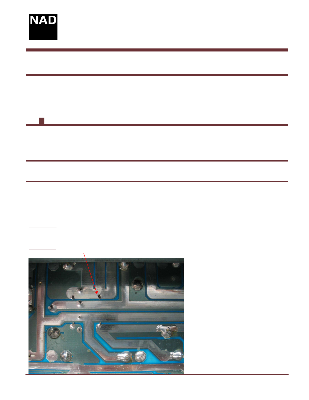
REASON:Solder pads around jumper wires have higher than normal resistance causing power
supply ripple to increase across filter capacitors. See figure 1.
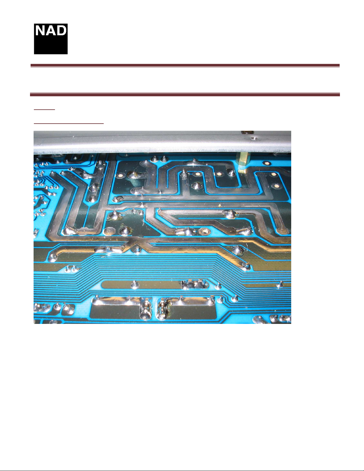
SOLUTION:Add 18 gauge wires to thePCB to lower the circuit resistance.To install this
modification, first remove the bottom service plate. Look for the PCB area shown in figure 2.
In figure 3, the addition of black jumper wires to lower the resistance of these pc board traces
is shown. Capacitors showing any signs of stress or damage should also be replaced at the
same time.
Warning: Check the correct polarity after performing this change . Use a variac to bring up
supply voltage to ensure proper polarity. Failure to do this check could destroy capacitors!!
Figure 1 (Original layout, showing cracked solder on jumper wire)
Product: Integrated Amplifier
Hardware Technical Bulletin: C372-H2005-01
June 1/05 Subject: Power supply capacitors
Implemented in production from serial number: H54C37210151
YES
NO
Page 1 of 4
Page 2
Technical Bulletin
Figure 2
Area of PCB to be modified
Product: Integrated Amplifier
Hardware Technical Bulletin: C372-H2005-01
C372
Page 2 of 4
Page 3

Technical Bulletin
C372
Figure 3
Addition of wires to PC Board area
Four wires shown below
Product: Integrated Amplifier
Hardware Technical Bulletin: C372-H2005-01
Page 3 of 4
Page 4

wire between these two pads
Technical Bulletin
C372
Figure 4
Alternative view showing four wires
Positive supply , add this
wire between these two pads
Product: Integrated Amplifier
Hardware Technical Bulletin: C372-H2005-01
Common/ground supply, add
these two wires as shown
between these pads
Contact:
NAD Electronics International
633 Granite Court
Pickering, ON Canada L1K 3K1
Voice: 905-831-0799 FAX 905-837-6357
www.nadelectronics.com
Negative supply , add this
Page 4 of 4
 Loading...