


NAD 310
GB
F
•OWNER'S MANUAL
•MANUEL D'INSTALLATION
D• BEDIENUNGSANLEITUNG
E• MANUAL DEL USUARIO
I • MANUALE DELLE ISTRUZIONI
S • BRUKSANVISNINGARNA
WARNING:TO PREVENT FIRE OR ELECTRIC SHOCK, DO NOT EXPOSE THIS APPLIANCE TO RAIN OR MOISTURE
Note to CATV system installer: This reminder is provided to call the CATV installer's attention to Article 820-40 of the NEC , which provides guidelines for proper grounding and, in particular, specifies that the cable should be connected to the grounding system of the building, as close to the point of cable entry as practical.
CAUTION: TO PREVENT ELECTRIC SHOCK, MATCH WIDE BLADE OF PLUG TO WIDE SLOT, FULLY INSERT.
ATTENTION: POUR EVITER LES CHOCS ELECTRIQUES, INTRODUIRE LA LAME LA PLUS LARGE DE LA FICHE DANS LA BORNE CORRESPONDANTE DE LA PRISE ET POUSSER JUSQU’AU FOND.
The lightning flash with arrowhead, within an equilateral tri- |
The exclamation point within an equilateral triangle is intend- |
angle is intended to alert the user of the presence of unin- |
ed to alert the user of the presence of important operating |
sulated "dangerous voltage" within the product's enclo- |
and maintenance (servicing) instructions in the literature |
sure; that may be of sufficient magnitude to constitute a |
accompanying the appliance |
risk of electric shock to persons. |
|
|
|
NAD 310 STEREO INTEGRATED AMPLIFIER
REAR PANEL CONNECTIONS |
|
CAUTION |
|
|
|
RISK OF ELECTRIC |
|
|
|
SHOCK DO NOT OPEN |
|
|
CAUTION: TO REDUCE THE RISK OF ELECTRIC |
||
|
SHOCK, DO NOT REMOVE COVER (OR BACK). |
||
|
NO USER SEVICEABLE PARTS INSIDE. |
||
|
REFER SERVICING TO QUALIFIED |
||
|
|
SERVICE PERSONNEL. |
|
ATTENTION:
RISQUE DE CHOC ELECTRIQUE
NE PAS OUVRIR
AFIN DEVITER UN CHOC ELECTRIQUE, ET LES CONSEQUENCES GRAVES QUI POURRAIENT EN RESULTER, TENTEZ PAS D'OUVRIR L'APPAREIL ET DE TOUCHER AUX COMPOSANTS INTERNES SANS LA PRESENCE D'UNE SERVICE PERSONNEL.
NAD 2

FRONT PANEL CONTROLS
FIGURE 1.
FIGURE 2.
C
E
R
|
|
T |
|
|
U |
|
|
P |
|
|
T |
|
|
U |
|
E |
O |
|
P |
|
|
A |
|
T |
T |
|
U |
|
|
P |
|
|
IN |
|
|
NAD 3

GB NAD 310 STEREO INTEGRATED AMPLIFIER
INSTRUCTIONS FOR INSTALLATION
AND OPERATION
A NOTE ON INSTALLATION
This unit may be installed on any stable surface. Since its power transformer (near the left-rear corner) generates a magnetic hum field of moderate strength, an LP turntable should not be located directly to its left.
The amplifier also generates a modest amount of heat and thus requires some ventilation. Do not place it on a rug or other soft surface that it could sink into, obstructing the air inlets on its bottom. And do not allow papers or cloth to obstruct the ventilation grille in the top cover.
CAUTION: To prevent a fire or shock hazard, do not permit this product to become wet. If liquid is accidentally spilled on it, immediately shut off its power and unplug the AC power cord. Allow sufficient time for complete evaporation to occur before operating the amplifier again. If the liquid is anything but water and/or alcohol, the amplifier should be examined by a service technician before power is applied to it.
Do not remove the cover, or attempt to modify or repair the amplifier yourself. Refer all servicing to a qualified technician.
REAR PANEL CONNECTIONS
1. AC LINE CORD
After you have completed all connections to the amplifier, plug the AC line cord into a “live” wall socket or into a heavy-duty extension cord.
WARNING TO UK USERS. If this appartus is not fitted with a UK three-pin plug, do not attempt to insert the attached plug into a UK mains socket. Instead, cut the plug from the mains lead and attach a fused UK three-pin plug using the following safety advice on wiring.
IMPORTANT. The wires in this mains lead are coloured BLUE and BROWN;
BLUE: NEUTRAL BROWN: LIVE
The colours of these mains lead wires may not correspond with the coloured markings identifying the terminals in your plug. In this case the BROWN wire must be connected to the terminal which is marked L(ive) or coloured RED. The BLUE wire must be connected to the terminal marked N(eutral) or coloured BLACK. No connection should be made to the terminal marked E or coloured green or green and yellow
2. SPEAKER TERMINALS.
Use these high-current binding-post terminals to connect your main stereo speakers. Each binding post consists of a threaded metal shaft and a red or black plastic screw-on bushing.
NAD 4
Connect the wires from your left-channel speaker to the (L+) and (L-) terminals, and connect the wires from the right-channel speaker to the (R+) and (R-) terminals. In each channel the red terminal is the positive (+) output, and the black terminal is the negative (-) or “ground” terminal. For best stereo imaging, the left and right speakers should be located at equal distances from your chair.
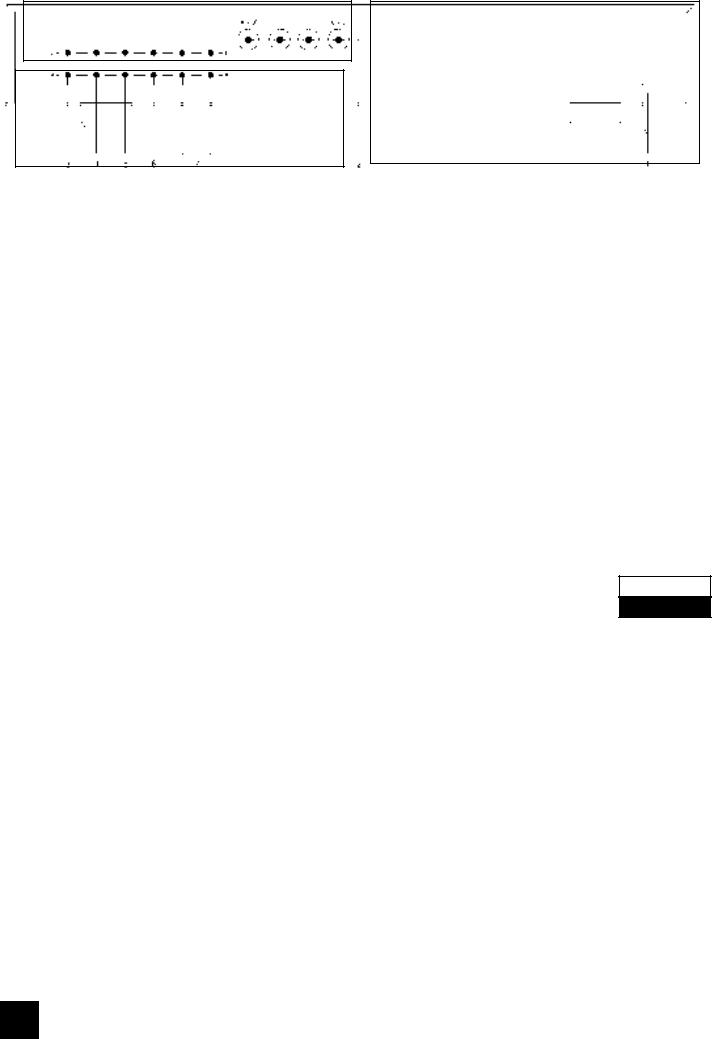
Use heavy-duty (1.5mm2, 16-gauge, or thicker) stranded wire, especially with 4-ohm loudspeakers. Bare wires can be connected directly to the bindingpost terminals. For a longer-lasting and more corro- sion-resistant connection you may purchase speaker cables with nickel or gold-plated connectors (spade lugs, banana plugs, or pin connectors), or install such connectors on the wires yourself. Connections to each binding post may be made in several ways, as follows. [Figure 1.]
(1)Pin connectors. A pin connector is a slim metal shaft that is crimped or soldered onto the end of a wire. The binding posts accept pin connectors up to 3mm in diameter. Unscrew the plastic bushing on each terminal to expose the hole in the metal shaft. Insert the pin connector through the hole, and turn the bushing clockwise until it is tight.
(2)Spade lugs. Unscrew the colored bushing, insert the U-shaped spade lug behind the bushing, and tighten the bushing down on it.
(3)Banana plugs. Insert a banana plug directly into the hollow end of each binding post. The terminals are separated by 3/4 inch (19mm), so they will accept dual-banana plugs. Before using banana plugs, the red and black inserts have to be removed with the aid of a small screwdriver.
(4)Bare wires. Separate the two conductors of the cord, and strip off a half-inch (1 cm) of insulation from each. In each conductor, twist together the exposed wire strands. Unscrew the red or black bushing, insert the bare wire through the hole in the metal shaft, and tighten the plastic bushing until it grasps the wire securely. Check to be sure that no loose strand of wire is touching the chassis or an adjacent terminal.
Phasing. Stereo speakers must operate “in phase” with each other in order to produce a focused stereo image and to reinforce rather than cancel each other’s output at low frequencies. An in-phase connection is assured if the red (positive) terminal on the amplifier is connected to the red (positive) terminal on the loudspeaker, in each channel. Methods of checking for correct phasing are described in the Appendix.
3. CD INPUT.
Connect the audio signal cables from a Compact Disc player to these jacks. (NOTE: this input is for an audio signal, not for the digital-code output of a CD player.) If you don’t have a CD player, any other linelevel signal source (such as a MiniDisc player or a spare tape deck) may be connected to the CD input.
4. TUNER INPUT.
Connect the audio signal cable from a radio tuner (AM, FM, or digital radio) to this pair of jacks.

5. AUX INPUT.
Any “line-level” audio signal can be connected here, such as the playback signal from a second CD player, or with an external step-up amplifier, a turntable.
6. VIDEO SOUND INPUT.
Connect a video-related audio signal here, such as the audio output from a video cassette recorder, laserdisc player, TV monitor/receiver, or stereo television decoder. Alternatively, any “line-level” audio signal may be connected here, such as the playback from a spare tape deck.
7. TAPEPLAY/REC.
These jacks allow you to connect tape recorder of any type, especially a high-performance cassette or open-reel recorder whose independent recording and playback heads allow you to monitor the signal on the tape immediately after it is recorded. Connect a stereo cable from the TAPE REC jacks of this amplifier to the recorder’s LINE IN jacks, and a second cable from the recorder’s LINE OUT jacks to these TAPE PLAY jacks.
The TAPE jacks may be used for a signal-process- ing accessory instead of a tape recorder. Examples of such accessories include a dynamic range processor, a noise filter, or a graphic equalizer. Connect a patch cord from the TAPE REC jacks to the processor’s inputs, and another patch cord from processor’s outputs to the TAPE PLAY jacks.
FRONT PANEL CONTROLS
1. POWER.
Press this button to switch on the amplifier. To switch the power off, press the button again and release it.
NOTE: When the amplifier is switched off with a source (such as a CD) still playing there will still be sound for as much as several seconds, depending on the volume level, before it eventually dies out. Although completely harmless, it can be avoided switching off the source first or by turning down the volume first.
CAUTION: In the off position the unit is still connected to the mains. Disconnect the power cable when the unit is not to be used for a long time.
2. BASS.
The Bass control adjusts the relative level of the low frequencies in the sound. The response of the amplifier is flattest when the control is set in the detent at the 12 o’clock position. Rotation of the knob to the right (clockwise) increases the level of low-fre- quency sounds, and rotation counter-clockwise decreases their level.
The Bass control has no effect if the TONE DEFEAT button is engaged.
At moderate rotations away from center the effect of the Bass control is subtle, because its action is
GB
confined to the lowest audible frequencies, which are not present in some recordings. Only at large rotations away from center is there a substantial boost or cut at the mid-bass frequencies that are common in music.
3. TONE DEFEAT.
When this button is pressed the Bass and Treble circuits are completely bypassed, restoring precisely flat frequency response. When this button is OUT the tone controls operate normally. By adjusting the tone controls and then switching them in and out of the signal path, you can evaluate their effect on the sound.
4. TREBLE.
The Treble control adjusts the relative level of the high frequencies in the sound. The response of the amplifier is flattest when the control is set in the detent at the 12 o’clock position. Rotation of the Treble control to the right (clockwise) increases the level of high-frequency sounds, and rotation counterclockwise decreases their level. Adjust the Treble control to achieve the tonal balance that sounds most natural to you.
Boosting the Treble increases the brilliance and clarity of details in the sound, but also makes any noise more prominent. Turning down the Treble makes the sound mellower while suppressing hiss and record surface noise; but too much Treble roll-off will make the sound dull.
The Treble control has no effect if the TONE DEFEAT button is engaged.
NOTE: At high volume settings (with the volume control over the 12 o’clock position) both the Bass and Treble controls do not have any effect anymore.
5. POWER INDICATOR.
The POWER indicator glows green when the amplifier is switched on and ready for use.
6. PROTECTION INDICATOR.
The amplifier incorporates protection circuitry against conditions such as overheating, short circuits, and DC off-set. Under normal conditions, this indicator will not light up and the unit will operate normally. If however one of the decribed conditions occur, the indicator will light up red and the unit will stop working.
TURN DOWN the volume all the way and SWITCH OFF the amplifier IMMEDIATLY.
Investigate the cause for the protection circuitry to trip, such as a short circuit in any of the speaker leads or any wire touching an adjecant terminal at either the amplifier’s or loudspeaker’s end.
If overheating was the cause (the amplifier’s casing will be very warm) ensure the ventilation slots at the bottom and top are not blocked. Overheating can also occur by playing very loud for a prolonged time. Wait for a couple of minutes for the amplifier to cool down before switching it on again.
If the protection circuitry remains engaged, even after the amplifier has cooled down sufficiently and all
NAD 5

GB
connections have been checked you will have to consult your NAD dealer.
7. PORTABLE RECORD / PLAY JACKS
These jacks accept 3.5mm stereo Mini-Jacks, as used by most portable equipment such as Walkmans, Mini Disc and DCC recorders, portable CD players etc. Besides portables, regular “full sized” Hi Fi components such as a CD player, cassette deck or VCR can be connected to these jacks as well.
For playback, connect a patch cord from the portable’s headphone output to the PORTABLE PLAY jack on the amplifier’s front panel.
To record, connect a patch cord from the amplifier’s PORTABLE RECORD jack to the portable’s LINE IN jack(s) - not its microphone inputs.
If your tape recorder has separate record and playback heads and is designed to allow the recorded signal on the tape to be monitored, use the TAPE connections on the amplifier’s rear panel for that recorder.
PORTABLE / TAPE MONITOR
PORTABLE: Press the PORTABLE button IN to listen to the source connected to PORTABLE PLAY jack.
Note: When PORTABLE is selected, the signal from the portable source will mix with whichever rear panel input is selected. This will not normally cause a problem if the selected source is in stop mode. However it may be preferable to either select an unused input or, if all inputs are used, switch off all the inputs by lightly pressing any of the input selector buttons so that they are all positioned OUT. Ensure that the TAPE MONITOR button out also.
When the PORTABLE button is OUT, the selected rear panel source signal will be fed to the PORTABLE RECORD jack. To record from a line input, the TAPE MONITOR button must be OUT. To record from TAPE, the TAPE MONITOR button must be IN.
TAPE MONITOR: The TAPE MONITOR button lets you listen to the output signal from a tape deck or signal processor connected to the TAPE jacks on the rear panel. Press IN to engage, press again (OUT) to disengage.
When TAPE MONITOR is engaged, the source chosen by the INPUT SELECTOR continues to be fed to the TAPE REC jacks for recording or processing, but the signal returning from the tape recorder or signal processor is selected for listening.
TAPE MONITOR has no effect on signals that are being recorded from the rear panel inputs to TAPE REC. However it does switch signals going to PORTABLE RECORD (see above).
If you have a three head tape recorder that permits “off the tape” monitoring, then by engaging the TAPE MONITOR buttons on both the amplifier and the recorder, you can hear the playback signal from the tape recorder immediately after it is recorded, enabling you to check its quality.
With two head recorders, Hi Fi VCRs and most digital recorders, the monitored signal heard whilst recording is not from the tape but is merely the
NAD 6
signal passing through the recorder’s electronics (including its recording level controls). In this case the TAPE MONITOR allows you to check the left/right balance of the signal as it is recorded.
Note: If TAPE MONITOR is engaged with no recorder connected to TAPE PLAY, or with a recorder connected but not running, you will only hear the source connected to PORTABLE PLAY. If nothing is connected to this input you will only hear silence regardless of the settings of any other controls.
Tape dubbing: Two way dubbing is possible. To record from a PORTABLE source, the PORTABLE button should be IN and the TAPE MONITOR button OUT. To record from TAPE to a PORTABLE, the PORTABLE button should be OUT and the TAPE MONITOR button IN. Monitoring of the recorded signal is only possible when dubbing to the PORTABLE by using its headphones.
Note: Tape copying is a convenience intended for personal use. If you copy commercially produced recordings and sell or give away the copies, you may be violating the copyright or the property rights of the producer of the recording.
8.INPUT SELECTORS (VIDEO, AUX, TUNER, CD).
These buttons select the rear panel input signal for the amplifier. The selected signal is also fed to TAPE REC for recording purposes.
9.VOLUME LEFT/RIGHT.
The volume control adjusts the overall loudness level of the sound for both the left and right channel. It has no effect on the level of the signals fed to the TAPE REC or PORTABLE RECORD jacks.
The volume control consists of two independent controls for the left and right channels which are friction coupled. To alter the left/right balance, hold one section and set the other to the desired level. The rear section controls the left channel, the front section the right channel.
By turning the volume of both channels down all the way, equal setting for both left and right channels can be restored. The indicator groove will line up again.
APPENDIX:
ELICITING THE BEST PERFORMANCE FROM YOUR NAD 310 AMPLIFIER
Making sure that your speakers are in phase.
Stereo speakers should operate in phase with each other in order to provide a good stereo image and to reinforce rather than cancel each other’s output at low frequencies. If your speakers are easily moved, their phasing can easily be checked. Make the connections to both speakers, place the speakers face- to-face only a few inches apart, play some music, and listen. Then swap the connection of the two wires at the back of ONE speaker, and listen again. The connection which produces the fullest, boomiest bass output is the correct one. Connect the wires securely

to the speaker terminals, being careful not to leave any loose strands of wire that might touch the wrong terminal and create a partial short-circuit. Then move the speakers to their intended locations.
If the speakers cannot easily be set face-to-face, phasing must rely on the “polarity” of the connecting wires. Note that the SPEAKERS terminals on the amplifier are color coded: in each channel the red terminal has positive “+” polarity and the black terminal is negative “-”. The terminals at the rear of the speakers are also marked for polarity, either via red and black connectors or by labels: “+”, 1, or 8 ohms for positive, “-”, 0, or G for negative. As a general rule the positive (red) terminal on the amplifier should be connected to the positive terminal of the speaker, in each channel.
To facilitate this, the two conductors comprising the speaker wire in each channel are different, either in the color of the wire itself (copper vs. silver) or in the presence of a small ridge or rib pattern on the insulation of one conductor. Use this pattern to establish consistent wiring to both speakers of a stereo pair. Thus if you connect the copper colored wire (or ribbed insulation) to the red amplifier terminal in the Left channel, do the same in the Right channel. At the other end of the wire, if you connect the copper colored wire (or the ribbed insulation) to the red or positive terminal on the left-channel speaker, do the same at the right-channel speaker.
GB
A note on overload protection.
Because NAD amplifiers sound so clean and musical when driven beyond their nominal power ratings and when used to drive low-impedance loudspeakers, you may be tempted to stress your amplifier beyond its design capacity. It can safely and cleanly drive complex speaker impedances with wide-range musical signals whose peak level is 40 watts or more, but it may overheat if called upon to deliver high power CONTINUOUSLY into a low impedance.
Thus you may play music at volume levels that cause the brief transient peaks and climaxes in music to exceed the amplifier’s rated power by a considerable margin. But if you overdrive the amplifier continuously rather than only on peaks, the output transistors may overheat.
This is particularly likely if you try to drive two pairs of speakers, or speakers having a very low impedance, at high volume levels. If the amplifier stops playing and the “Protection” indicator glows red, switch off the power for a few minutes and allow the output stage to cool. If overheating was the fault, the amplifier will operate normally when it is turned back on. But severe abuse of this type may cause internal fuses to blow to protect the amplifier. If the amplifier stops playing and the green Power LED ceases to glow, return the amplifier to a NAD dealer for service.
IN CASE OF DIFFICULTY: A TROUBLE-SHOOTING GUIDE |
|
SYMPTOM |
POSSIBLE CAUSE |
No sound. |
Power not turned on. |
|
AC line cord unplugged, or plugged into dead outlet. (To check the |
|
AC outlet, plug in an electric lamp.) |
|
Tuner selected but turned off or tuned to a blank frequency between |
|
stations. |
|
Inoperative input selected (e.g. CD input selected with no CD |
|
playing). |
|
Tape Monitor engaged with no tape playing. |
|
Internal fuses blown; return amplifier to dealer for service. |
No sound in one channel |
Volume control for one of the channels is turned down. Check the |
|
concentric volume control and ensure that both left and right are at |
|
an equal level. |
|
Loudspeaker connecting wire pulled loose. (Check all connections, |
|
both at the speakers and at the amplifier.) |
|
Connecting cable pulled loose or making poor contact in socket. |
|
Rotate plugs in jacks to restore contact. |
|
Short-circuit in a defective connecting cable. Wiggle all cables, |
|
especially where they enter plugs. |
Loud buzz and hum. |
Dirty contact in a switch. Exercise all front-panel switches to |
|
restore clean wiping contact. |
|
Connnecting cable pulled partially out of its jack. |
|
Defective connecting cable. |
Hum in tape playback |
Tape deck located too close to amplifier (directly above or below). |
|
Tape deck located too close to television set. |
|
Plugs making poor contact in jacks. |
Weak bass, diffuse stereo imaging |
Speakers wired out of phase. Swap connections at the back of |
|
ONE speaker. |
NAD 7

F AMPLIFICATEUR STEREO INTEGRE NAD 310
INSTRUCTIONS CONCERNANT
L’INSTALLATION ET LE FONCTION-
NEMENT
NOTE CONCERNANT L’INSTALLATION
Ce matériel peut être installé sur n’importe quelle surface stable. Etant donné que son transformateur de puissance (situé dans le coin arrière gauche) génère un champ de bourdonnement magnétique de puissance moyenne, il faut éviter de placer une platine tourne-disque 33 tours juste à gauche de l’amplificateur.
L’amplificateur génère aussi une petite quantité de chaleur, et nécessite donc une certaine ventilation. Ne pas le placer sur un tapis ou sur une surface molle dans laquelle il est susceptible de s’enfoncer, ce qui aurait pour effet d’obstruer les ouïes de ventilation sur sa face inférieure. Faire attention, aussi, à ce que la grille de sortie d’air située sur le panneau supérieur ne soit pas obstruée par des papiers ou chiffons.
ATTENTION : Pour prévenir tout risque d’incendie ou de choc électrique, éviter de mouiller ce matériel. En cas de déversement accidentel de liquide sur le matériel, couper immédiatement l’alimentation électrique et débrancher le câble d’alimentation secteur. Attendre l’évaporation totale du liquide avant de faire fonctionner l’amplificateur à nouveau. S’il s’agit d’un liquide autre que de l’eau et/ou de l’alcool, faire vérifier l’amplificateur par un technicien d’entretien avant de le remettre sous tension.
Ne pas enlever le couvercle, ou tenter de modifier ou réparer l’amplificateur soi-même. Confier tout travail d’entretien à un technicien qualifié.
BRANCHEMENTS SUR LE PANNEAU
ARRIERE
1. Cordon secteur C.A.
Après avoir effectué tous les branchements au niveau de l’amplificateur, brancher le cordon secteur à une prise de courant murale en bon état de fonctionnement, ou à une rallonge forte puissance.
2. Bornes haut-parleurs.
Utiliser ces bornes serre-fils gros calibre pour brancher les haut-parleurs stéréophoniques principaux. Chaque borne serre-fils est constituée d’une tige métallique filetée et d’une bague-écrou en plastique rouge ou noir.
Brancher les fils du haut-parleur gauche sur les bornes (L+) et (L-) et ceux du haut-parleur droit sur les bornes (R+) et (R-). Pour chaque voie, la borne rouge correspond à la sortie positive (+) et la borne noire à la borne négative (-) ou “masse”. Afin d’obtenir la meilleure image stéréo, les haut-parleurs gauche et droit doivent se trouver à égale distance de votre fauteuil.
NAD 8
Brancher les haut-parleurs avec du fil torsadé haute puissance (1,5 mm2, calibre 16 ou plus), surtout s’il s’agit de haut-parleurs 4 ohms. Des fils dénudés peuvent être branchés directement sur les bornes serre-fils. Pour un branchement plus durable et plus résistant à l’oxydation, il est possible de se procurer des câbles de haut-parleurs munis de connecteurs nickelés ou plaqués or (connecteurs à broche, cosses plates ou fiches banane) ; on peut même monter ces types de connecteurs sur les câbles soi-même.
Les branchements sur les bornes serre-fils peuvent être réalisés de plusieurs manières différentes, comme indiqué ci-après [Cf. Figure 1] :
(1)Connecteurs à broche. Un connecteur à broche est une mince tige en métal que l’on sertit ou que l’on soude à l’extrémité d’un fil. Les bornes serre-fils comportent un trou prévu pour des connecteurs à broche de diamètre inférieur ou égal à 3 mm. Dévisser la bague filetée de chaque borne pour découvrir le trou dans l’axe métallique. Insérer le connecteur à broche dans le trou, puis serrer la bague-écrou en la vissant en sens horaire.
(2)Cosses plates. Dévisser la bague-écrou colorée, insérer la cosse plate en forme de U sous la bague-écrou, puis revisser cette dernière pour retenir la cosse.
(3)Fiches bananes. Insérer une fiche banane directement dans l’extrémité de chaque borne serrefils. Les bornes ont un espacement de 19 mm, ce qui permet d’y brancher des fiches bananes doubles. Avant de pouvoir utiliser des fiches banane, il faut d’abord retirer les inserts rouge et noir à l’aide d’un petit tournevis.
(4)Fils dénudés. Séparer les deux conducteurs du câble, et les dénuder sur une longueur d’1 cm environ. Pour chaque conducteur, torsader ensemble les brins de fil dénudés. Dévisser la bague-écrou rouge ou noire de quelques tours, insérer le fil dénudé dans l’orifice de l’axe métallique, puis revisser la bagueécrou et la serrer de manière à ce qu’elle maintienne fermement le fil. Vérifier qu’aucun brin des fils ne s’est échappé, et ne touche une borne adjacente ou le châssis.
Phasage. Les haut-parleurs stéréophoniques doivent fonctionner en phase les uns avec les autres, de manière à obtenir une bonne reproduction stéréophonique et à renforcer, plutôt qu’annuler, la sortie sonore de chacun aux basses fréquences. Un branchement en phase s’obtient en reliant, pour chaque voie, la borne rouge (positive) à l’arrière de l’amplificateur à la borne rouge (positive) du haut-par- leur de chaque voie. Des méthodes permettant de vérifier le phasage correct sont décrites dans l’Annexe.
3. ENTREE CD [CD INPUT].
Relier les câbles de signal audio d’un lecteur de compact disques numérique à ces jacks. (NOTA : Cette entrée est destinée à un signal audio, et non à la sortie numérique d’un lecteur CD). Si l’on n’a pas de lecteur CD, toute autre source de signal niveauligne (comme un lecteur MiniDisc ou un magnéto-

phone auxiliaire par exemple) peut être reliée à l’entrée CD.
4. ENTREE TUNER [TUNER INPUT].
Relier le câble de signal audio d’un tuner radio (AM, FM ou RDS) à cette paire de jacks.
5. ENTREE AUX [AUX INPUT].
N’importe quel signal audio de niveau-ligne peut être relié à cette entrée, comme par exemple le signal de lecture d’un deuxième lecteur de CD, ou d’un tourne-disque équipé d’un amplificateur élévateur.
6.ENTREE SON VIDEO [VIDEO SOUND INPUT].
Relier à cette entrée un signal audio lié à l’image, comme par exemple la sortie audio d’un magnétoscope, d’un lecteur de disques optiques, d’un moniteur ou récepteur TV ou d’un décodeur de télévision stéréophonique. Autrement, n’importe quel signal audio “niveau-ligne” (une platine magnétophone supplémentaire, par exemple) peut être relié cette entrée.
7.LECTURE BANDE/ENREGISTREMENT BANDE [TAPE PLAY/REC].
On peut utiliser ces jacks pour brancher un magnétophone de n’importe quel type, et plus spécialement un magnétophone haute performance à cassette ou à bobines, dont les têtes indépendantes d’enregistrement et de lecture permettent le contrôle direct du signal sur la bande juste après son enregistrement. Brancher un cordon stéréo entre les jacks ENREGISTREMENT BANDE [TAPE REC] de cet amplificateur et les jacks ENTREE LIGNE du magnétophone et un deuxième cordon entre les jacks SORTIE LIGNE du magnétophone et ces jacks LECTURE BANDE [TAPE PLAY].
Il est possible d’utiliser les jacks LECTURE BANDE [TAPE PLAY]. pour brancher un accessoire de traitement du signal à la place d’un magnétophone. Des exemples de tels dispositifs sont un processeur de plage dynamique, un dispositif de filtrage du bruit ou un égaliseur graphique. Brancher un cordon entre les jacks de ENREGISTREMENT BANDE [TAPE REC] et les jacks d’entrée niveau ligne du processeur, et un deuxième cordon entre les jacks de sortie du processeur de signal et les jacks de LECTURE BANDE [TAPE PLAY].
COMMANDES SUR LA FACADE
1. MARCHE/ARRET [POWER].
Appuyer sur ce bouton poussoir pour allumer l’amplificateur. Pour éteindre l’amplificateur, appuyer une nouvelle fois sur le bouton poussoir Marche/Arrêt puis le relâcher.
NOTA : si l’on met l’amplificateur hors tension, alors qu’une source de signal (lecteur CD, par exemple) est toujours en train de fonctionner, le son per-
F
sistera pendant un certain temps, parfois plusieurs secondes, avant de s’étouffer ; la durée de la persistance dépendra du volume sonore affiché au moment de la mise hors tension.
Bien que ce phénomène soit totalement inoffensif, il est possible de l’éviter soit en arrêtant la source, soit en baissant le volume, avant de mettre l’amplificateur hors tension.
CAUTION: En position hors tension (“Off”), l’appareil reste relié au secteur. En cas de période prolongée de non utilsation, débrancher le câble d’alimentation.
2. GRAVES [BASS].
La commande des Graves règle le niveau relatif des basses fréquences dans la sonorité. La courbe de réponse de l’amplificateur est la plus plate lorsque ce bouton est réglé dans l’encoche en position “12 heures”. En tournant le bouton vers la droite (sens des aiguilles d’une montre), on augmente le niveau des sons basse fréquence, et on le diminue en le tournant vers la gauche (sens inverse des aiguilles d’une montre).
La commande des Graves n’aura aucun effet si le bouton TONALITE NEUTRE [TONE DEFEAT] est enfoncé.
Tout mouvement modéré de la commande dans un sens ou dans l’autre, par rapport à la position centrale, a un effet subtil car son influence est alors limitée aux fréquences audibles les plus basses, absentes dans certains enregistrements. Ce ne sont que les mouvements plus importants par rapport à la position centrale qui produiront une augmentation ou une diminution notable des fréquences basses moyennes le plus souvent présentes dans la musique.
3. TONALITE NEUTRE [TONE DEFEAT].
Les circuits de tonalité “Graves” et “Aigus” sont contournés lorsque ce bouton-poussoir est enfoncé, ce qui permet d’obtenir une courbe de réponse de fréquence parfaitement plate. Lorsque ce boutonpoussoir est en position Sorti [OUT], les commandes de tonalité fonctionnent normalement. En réglant ces commandes, puis en les basculant hors-circuit et encircuit, il est facile d’en évaluer l’effet sur la sonorité musicale.
4. AIGUS [TREBLE].
La commande des Aigus règle le niveau relatif des fréquences élevées dans la sonorité. La courbe de réponse de l’amplificateur est la plus plate lorsque ce bouton est réglé dans l’encoche en position “12 heures”. En tournant le bouton vers la droite (sens des aiguilles d’une montre), on augmente le niveau des sons haute fréquence, et on le diminue en le tournant vers la gauche (sens inverse des aiguilles d’une montre). Régler la commande des Aigus pour obtenir l’équilibre de ton qui semble le plus naturel.
Un accroissement des aigus augmente l’éclat et la clarté des détails du son, mais accentue aussi tout autre bruit. Une diminution des aigus adoucit le son, et limite aussi le sifflement et le bruit lié à la surface des disques ; cependant, une atténuation trop importante des aigus entraîne un son plus mat.
NAD 9

F
La commande des Aigus n’a aucune influence lorsque le bouton TONALITE NEUTRE [TONE DEFEAT] est enfoncé.
NOTA : Aux niveaux sonores élevés (commande de volume sonore au delà de la position “12 heures”), les commandes des Graves et des Aigus n’ont plus aucun effet.
5.INDICATEUR DE MISE SOUS TENSION [POWER]
La LED d’alimentation “POWER” s’allume en vert lorsque l’amplificateur est sous tension et prêt à fonctionner.
6.INDICATEUR DE PROTECTION [PROTECTION INDICATOR]
L’amplificateur comporte des circuits de protection contre les conditions telles que le sur-échauffement, les courts-circuits et le décalage du courant continu. Dans des conditions normales, cet indicateur ne s’allume pas et l’appareil fonctionne normalement. Si, par contre l’une des conditions décrites se produit, l’indicateur s’allume et l’amplificateur cesse de fonctionner.
BAISSER le volume sonore jusqu’au minimum, et ARRETER l’amplificateur IMMEDIATEMENT (le mettre hors tension).
Rechercher la cause du déclenchement du circuit de protection : un court-circuit dans l’un des fils des câbles des haut-parleurs, ou un fil quelconque touchant une borne adjacente côté amplificateur ou côté haut-parleur, par exemple.
Si la cause de l’indication est un sur-échauffement (le boîtier de l’amplificateur est très chaud), vérifier que les ouïes de ventilation sur les faces inférieure et supérieure ne sont pas obstruées. Un sur-échauffe- ment peut aussi être dû à une écoute à un volume sonore très élevé pendant une longue période. Attendre quelques minutes que l’amplificateur refroidisse avant de le remettre sous tension.
Si les circuits de protection restent déclenchés même après un temps de refroidissement suffisant, et après vérification de tous les branchements, il sera nécessaire de consulter votre revendeur NAD.
7. JACKS D’ENREGISTREMENT / LECTURE D’APPAREILS PORTABLES [PORTABLE RECORD / PLAY]
Ces prises jack sont prévues pour les Mini-Jacks stéréophoniques 3,5 mm utilisés par la plupart des matériels portables tels que les Baladeurs, les lecteurs de Mini-Disques, les lecteurs/enregistreurs de cassettes numériques, les lecteurs de CD portables, etc. ... En plus des appareils portables, on peut aussi brancher sur ces jacks des appareils Hi-Fi de salon (“taille normale”), comme un lecteur CD, une platine cassette ou un magnétoscope.
Pour la lecture, brancher un cordon entre la SORTIE CASQUE du portable et le jack de LECTURE PORTABLE [PORTABLE PLAY] sur la face parlante de l’amplificateur.
NAD 10
Pour effectuer des enregistrements, brancher un cordon entre le jack d’ENREGISTREMENT PORTABLE [PORTABLE RECORD] et le/les jack(s) d’ENTREE LIGNE [LINE IN] de l’enregistreur (et non pas à ses entrées microphone).
Si votre enregistreur de bandes magnétiques possède des têtes de lecture et d’enregistrement distinctes, et a été conçu de manière à permettre le contrôle immédiat du signal sur la bande, utiliser les branchements de BANDE [TAPE] sur le panneau arrière de l’amplificateur pour cet enregistreur.
PORTABLE / MONITEUR D’ENREGISTREMENT [PORTABLE / TAPE MONITOR]
PORTABLE : ENFONCER le bouton-poussoir PORTABLE pour écouter la source branchée au jack de LECTURE PORTABLE [PORTABLE PLAY].
Nota : Lorsque la source PORTABLE a été sélectionnée, son signal est mélangé au signal de l’Entrée sélectionnée sur le panneau arrière. Cela ne pose aucun problème, en principe, à condition que la source sélectionnée soit en mode arrêté. Cependant, il est peut-être préférable de sélectionner une entrée non utilisée ou, si toutes les entrées sont déjà utilisées, de couper toutes les entrées en appuyant légèrement sur l’un quelconque des boutons sélecteurs interverrouillés, afin de désenclencher l’ensemble des boutons (qui seront alors SORTIS). Vérifier aussi que le bouton MONITEUR D’ENREGISTREMENT [TAPE MONITOR] est bien sorti.
Lorsque le bouton PORTABLE est SORTI, le signal de la source sélectionnée sur le panneau arrière est injecté dans le jack d’ENREGISTREMENT PORTABLE [PORTABLE RECORD]. Pour enregistrer à partir d’une entrée de niveau ligne, le bouton MONITEUR D’ENREGISTREMENT [TAPE MONITOR] doit être SORTI. Pour enregistrer à partir d’une BANDE [TAPE], le bouton MONITEUR D’ENREGISTREMENT [TAPE MONITOR] doit être ENFONCE.
MONITEUR D’ENREGISTREMENT [TAPE MONITOR] : Le bouton-poussoir MONITEUR D’ENREGISTREMENT [TAPE MONITOR] vous permet d’écouter le signal de sortie d’une platine magnétophone ou d’un processeur de signal branchés aux jacks de BANDE [TAPE] sur le panneau arrière. Appuyer sur ce bouton (l’ENFONCER) pour activer la fonction, puis appuyer à nouveau (le faire RESSORTIR) pour la désactiver.
Lorsque la fonction MONITEUR D’ENREGISTREMENT [TAPE MONITOR] est active, la source choisie à l’aide du sélecteur des entrées continue à être envoyée aux jeux de jacks d’ENREGISTREMENT BANDE [TAPE REC] pour enregistrement ou traitement, mais le signal renvoyé par le magnétophone ou par le processeur de signaux est actif à l’écoute.
La fonction MONITEUR D’ENREGISTREMENT [TAPE MONITOR] n’a aucun effet sur les signaux en cours d’enregistrement depuis les entrées sur le panneau arrière vers ENREGISTREMENT BANDE (TAPE REC]. Par contre, il commute bien les signaux envoyés au jack d’ENREGISTREMENT PORTABLE [PORTABLE RECORD] (voir ci-dessus).
 Loading...