

Page 1

be certain.
m
SWIFT® Mini Transducer Interface (TI)
Product Information
100-214-316 B
Page 2

Copyright information © 2009-2011 MTS Systems Corporation. All rights reserved.
Trademark information MTS, SWIFT, TestWare, RPC, and Remote Parameter Control are registered
trademarks of MTS Systems Corporation within the United States. These
trademarks may be protected in other countries.
Microsoft, Windows, Wi ndows for Workgroups, Windows 95, and Windows NT
are registered trademarks of Microsoft Corporation. Apple and Macintosh are
registered trademarks of Apple Computer, Inc. UNIX is a registered trademark of
The Open Group. LabVIEW is a registered trademark of National Instruments
Corporation. All other trademarks or service marks are property of their
respective owners.
Publication information
Manual Part Number Publication Date
100-214-316 A June 2009
100-214-316 B December 2011
Page 3

Contents
Technical Support 5
How to Get Technical Support 5
Before You Contact MTS 5
If You Contact MTS by Phone 7
Problem Submittal Form in MTS Manuals 8
Preface 9
Before You Begin 9
Conventions 10
Documentation Conventions 10
Hardware Overview 13
Overview 14
Spinning Applications (Track or Road) 16
Non-Spinning Applications (Laboratory) 17
Design Features 18
Coordinate System 19
Specifications 21
Calibration 22
Transducer Interface 24
TI Front Panel 27
TI Rear Panel 28
Software Utilities 29
Introduction 30
TI2STATUS - Transducer Interface Status 31
Description of TI2STATUS Indications 31
TI2XFER - Transducer Interface Transfer 33
TI2SHUNT - Transducer Interface Shunt 35
Error Messages 38
SWIFT® Mini TI
Contents
3
Page 4

Transducer Interface Setup 41
USB Driver Installation 42
Select a Zero Method 44
Calibration File Elements 45
Upload the Calibration File 47
Edit the Calibration File 48
Download the Calibration File 52
Installation 53
Transducer Interface Electronics Installation 54
SWIFT Sensor Setup for Data Collection 56
Quality of the Zero Procedure Verification 60
Data Collection 61
Road Simulator 63
Zero the Transducer Interface 64
Alternate zero procedures 67
Maintenance 71
Transducer Interface 71
Troubleshooting 73
4
Contents
SWIFT® Mini TI
Page 5

Technical Support
How to Get Technical Support
Start with your
manuals
Technical support
methods
The manuals supplied by MTS provide most of the information you need to use
and maintain your equipment. If your equipment includes software, look for
online help and README files that contain additional product inform ation.
If you cannot find answers to your technical questions from these sources, you
can use the Internet, e-mail, telephone, or fax to contact MTS for assistance.
MTS provides a full range of support services after your system is installed. If
you have any questions about a system or product, contact Technical Support in
one of the following ways.
www.mts.com The web site provides access to our technical support staff by means of an
onlineform:
www.mts.com > Contact MTS > Service & Technical Support button
E-mail tech.support@mts.com
Telephone MTS Call Center 800-328-2255
Weekdays 7:00 A.M. to 5:00 P.M., Central Time
Fax 952-937-4515
Please include “Technical Support” in the subject line.
Outside the U.S. For technical support outside the United States, contact your local sales and
service office. For a list of worldwide sales and service locations and contact
information, use the Global MTS link at the MTS web site:
Before You Contact MTS
Know your site
number and system
number
SWIFT® Mini TI
www.mts.com > Global MTS > (choose your region in the right-hand
column) > (choose the location closest to you)
MTS can help you more efficiently if you have the following information
available when you contact us for support.
The site number contains your company number and identifies your equipment
type (such as material testing or simulation). The number is typically written on a
label on your equipment before the system leaves MTS. If you do not know your
MTS site number, contact your sales engineer.
Example site number: 571167
When you have more than one MTS system, the system job number identifies
your system. You can find your job number in your order paperwork.
Example system number: US1.42460
Technical Support
5
Page 6

Know information from
prior technical
If you have contacted MTS about this problem before, we can recall your file
based on the:
assistance
• MTS notification number
• Name of the person who helped you
Identify the problem Describe the problem and know the answers to the following questions:
• How long and how often has the problem occurred?
• Can you reproduce the problem?
• Were any hardware or software changes made to the system before the
problem started?
• What are the equipment model numbers?
• What is the controller model (if applicable)?
• What is the system configuration?
Know relevant
computer information
Know relevant
software information
For a computer problem, have the following information available:
• Manufacturer’s name and model number
• Operating software type and service patch information
• Amount of system memory
• Amount of free space on the hard drive where the application resides
• Current status of hard-drive fragmentation
• Connection status to a corporate network
For software application problems, have the following information available:
• The software application’s name, version number, build number, and (if
available) software patch number. This information can typically be found
in the About selection in the Help menu.
• The names of other applications on your computer, such as:
– Anti-virus software
– Screen savers
– Keyboard enhancers
– Print spoolers
Technical Support
6
– Messaging applications
SWIFT® Mini TI
Page 7

If You Contact MTS by Phone
A Call Center agent registers your call before connecting you with a technical
support specialist. The agent asks you for your:
• Site number
• Name
• Company name
• Company address
• Phone number where you can be reached
If your issue has a notification number, please provide that number. A new issue
will be assigned a unique notification number.
Identify system type To enable the Call Center agent to connect you with the most qualified technical
support specialist available, identify your system as one of the following types:
• Electromechanical material test system
• Hydromechanical material test system
• Vehicle test system
• Vehicle component test system
Be prepared to
troubleshoot
Write down relevant
information
After you call MTS logs and tracks all calls to ensure that you receive assistance for your
• Aero test system
Prepare to perform troubleshooting while on the phone:
• Call from a telephone close to the system so that you can implement
suggestions made over the phone.
• Have the original operating and application software media available.
• If you are not familiar with all aspects of the equipment operation, have an
experienced user nearby to assist you.
In case Technical Support must call you:
• Verify the notification number.
• Record the name of the person who helped you.
• Write down any specific instructions.
problem or request. If you have questions about the status of your problem or
have additional information to report, please contact Technical Support again and
provide your original notification number.
SWIFT® Mini TI
Technical Support
7
Page 8

Problem Submittal Form in MTS Manuals
Use the Problem Submittal Form to communicate problems with your software,
hardware, manuals, or service that are not resolved to your satisfaction through
the technical support process. The form includes check boxes that allow you to
indicate the urgency of your problem and your expectation of an acceptable
response time. We guarantee a timely response—your feedback is important to
us.
Access the Problem Submittal Form:
• In the back of many MTS manuals (postage paid form to be mailed to MTS)
• www.mts.com > Contact Us > Problem Submittal Form button (electronic
form to be e-mailed to MTS)
Technical Support
8
SWIFT® Mini TI
Page 9

Preface
Before You Begin
Safety first! Before you use your MTS product or system, read and understand the Safety
manual and any other safety information provided with your system. Improper
installation, operation, or maintenance can result in hazardous conditions that can
cause severe personal injury or death, or damage to your equipment and
specimen. Again, read and understand the safety information provided with your
system before you continue. It is very important that you remain aware of
hazards that apply to your system.
Other MTS manuals In addition to this manual, you may receive additional manuals in paper or
electronic form.
You may also receive an MTS System Documentation CD. It contains an
electronic copy of the manuals that pertain to your test system, such as:
• Hydraulic and mechanical component manuals
• Assembly drawings
• Parts lists
• Operation manual
• Preventive maintenance manual
Controller and application software manuals are typically included on the
software CD distribution disc(s).
SWIFT® Mini TI
Preface
9
Page 10

Conventions
DANGER
WARNING
CAUTION
Conventions
Documentation Conventions
The following paragraphs describe some of the conventions that are used in your
MTS manuals.
Hazard conventions Hazard notices may be embedded in this manual. These notices contain safety
information that is specific to the activity to be performed. Hazard notices
immediately precede the step or procedure that may lead to an associated hazard.
Read all hazard notices carefully and follow all directions and recommendations.
Three different levels of hazard notices may appear in your manuals. Following
are examples of all three levels.
Note For general safety information, see the safety information provided with
your system.
Danger notices indicate the presence of a hazard with a high level of risk which,
if ignored, will result in death, severe personal injury, or substantial property
damage.
Warning notices indicate the presence of a hazard with a medium level of risk
which, if ignored, can result in death, severe personal injury, or substantial
property damage.
Caution notices indicate the presence of a hazard with a low level of risk which,
if ignored, could cause moderate or minor personal injury or equipment damage,
or could endanger test integrity.
Notes Notes provide additional information about operating your system or highlight
easily overlooked items. For example:
Note Resources that are put back on the hardware lists show up at the end of
the list.
Special terms The first occurrence of special terms is shown in italics.
Illustrations Illustrations appear in this manual to clarify text. They are examples only and do
not necessarily represent your actual system configuration, test application, or
software.
Electronic manual
conventions
This manual is available as an electronic document in the Portable Document
File (PDF) format. It can be viewed on any computer that has Adobe Acrobat
Reader installed.
10
Preface
SWIFT® Mini TI
Page 11

Conventions
Hypertext links The electronic document has many hypertext links displayed in a blue font. All
blue words in the body text, along with all contents entries and index page
numbers, are hypertext links. When you click a hypertext link, the application
jumps to the corresponding topic.
SWIFT
®
Mini TI
Preface
11
Page 12

Conventions
12
Preface
SWIFT® Mini TI
Page 13

Hardware Overview
Contents Overview 14
Spinning Applications (Track or Road) 16
Non-Spinning Applications (Laborator y) 17
Design Features 18
Coordinate System 19
Specifications 21
Calibration 22
Transducer Interface 24
TI Front Panel 27
TI Rear Panel 28
WEEE The Waste Electrical and Electronic Equipment (WEEE) symbol ( ) means
that the controller and its electronic parts must not be disposed of as unsorted
municipal waste. Proper disposal is required by approved electronic waste
collection agencies. Customers in the EC region who desire to return an end-oflife controller and its electronic parts are encouraged to contact your local MTS
Systems Sales/Service Offices for instructions.
SWIFT® Mini TI
Hardware Overview
13
Page 14
Overview
Data
S10-01
Track or Road
Laboratory Simulation
Overview
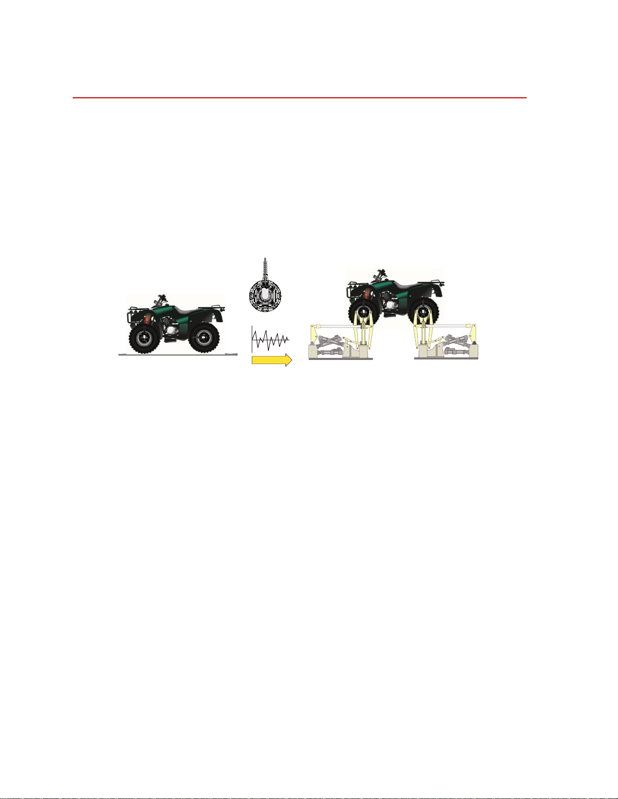
The MTS Spinning Wheel Integrated Force Transducer (SWIFT®) sensor is a
light-weight, easy-to-use transducer that enables you to conduct faster, less
expensive data acquisition and road simulation testing.
The transducer is designed for use on the test track and public roads, as well as in
the test laboratory. It attaches to the test vehicle or an MTS Series 329 Road
Simulator using an adapter and a modified wheel rim.
You can achieve excellent data correlation using the same transducer and vehicle
on the test track or public road and on a road simulator. It is available in various
sizes and materials to fit various vehicle and loading requirements.
Transducer Interface
(TI)
Additional
components
Parts replacement,
disassembly, and care
The TI provides power to the transducer and uses previously stored calibration
values to convert the raw transducer signals from the bridge outputs and the
encoder to three force outputs (Fx, Fy, Fz), three moment outputs (Mx, My, Mz)
and an angle or angular velocity output. The force and moment outputs have a
value of 10 V full scale, unless a different full-scale output is requested by a
customer. The angle output is a 0 to 5 V sawtooth output. The angular velocity
full scale can be configured in the calibration file.
Additional components that are supplied with your SWIFT sensor include
transducer data cables, TI power cable, a SWIFT Transducer Interface Utilities
CD or disk, and the calibration file. MTS can also provide a 12 V DC power
supply for use in the test laboratory.
The SWIFT sensor assembly, Transducer Interface box, and the accessory
components have no user serviceable parts. These components should not be
disassembled other than as outlined in “Troubleshooting” beginning on page 73.
14
Hardware Overview
SWIFT® Mini TI
Page 15

Overview
CAUTION
Do not disassemble the SWIFT sensor, Transducer Interface (TI) electronics,
and accessory components.
The SWIFT sensor, TI electronics, and accessory components are not
intended to be disassembled, other than as outlined in “Troubleshooting”.
Disassembling or tampering with these components may result in damage to the
sensor, loss of watertight seal, and voiding of the warranty.
SWIFT
®
Mini TI
Hardware Overview
15
Page 16
Spinning Applications (Track or Road)
Customer Supplied
Power Supply
Customer Supplied
Data Recorder
Transducer
Interface (TI)
Transducer Signals
Output
Signals
S10-02
(Battery or Vehicle power)
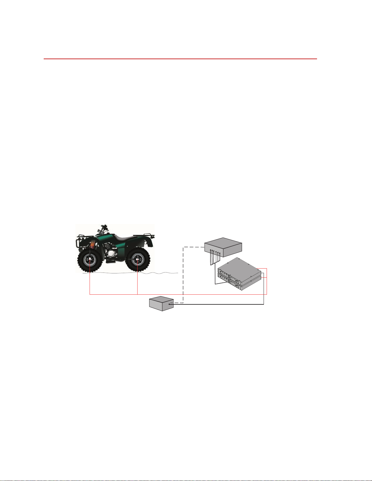
Spinning Applications (Track or Road)
The SWIFT sensor can be used for road load data acquisition (RLDA)
applications:
• Durability
• Noise, Vibration and Harshness (NVH)
• Ride and Handling
• Tire Performance
The transducer is durable enough to withstand harsh road testing and data
acquisition environments. The transducer is splash resistant and suitable for use
in conditions where the test vehicle will encounter occasional standing or running
water, or will be exposed to precipitation. However, it should not be submerged.
In a typical spinning application, the transducer is mounted on a modified rim of
a tire on a test vehicle, as shown in the following figure. The Transducer
Interface (TI), power supply, and data recorder can be securely mounted on a
carriage rack. The TI box should be protected against environmental conditions
(water and mud splashes and dust), and it should not be allowed to be immersed.
Hardware Overview
16
Spinning Application (Track or Road)
SWIFT® Mini TI
Page 17
Non-Spinning Applications (Laboratory)
Power Supply (with 4
connections)
Customer-Supplied
Test Control System
Transducer
Interface (TI)
Transducer Signals
Output
Signals
PC Communication
S10-03
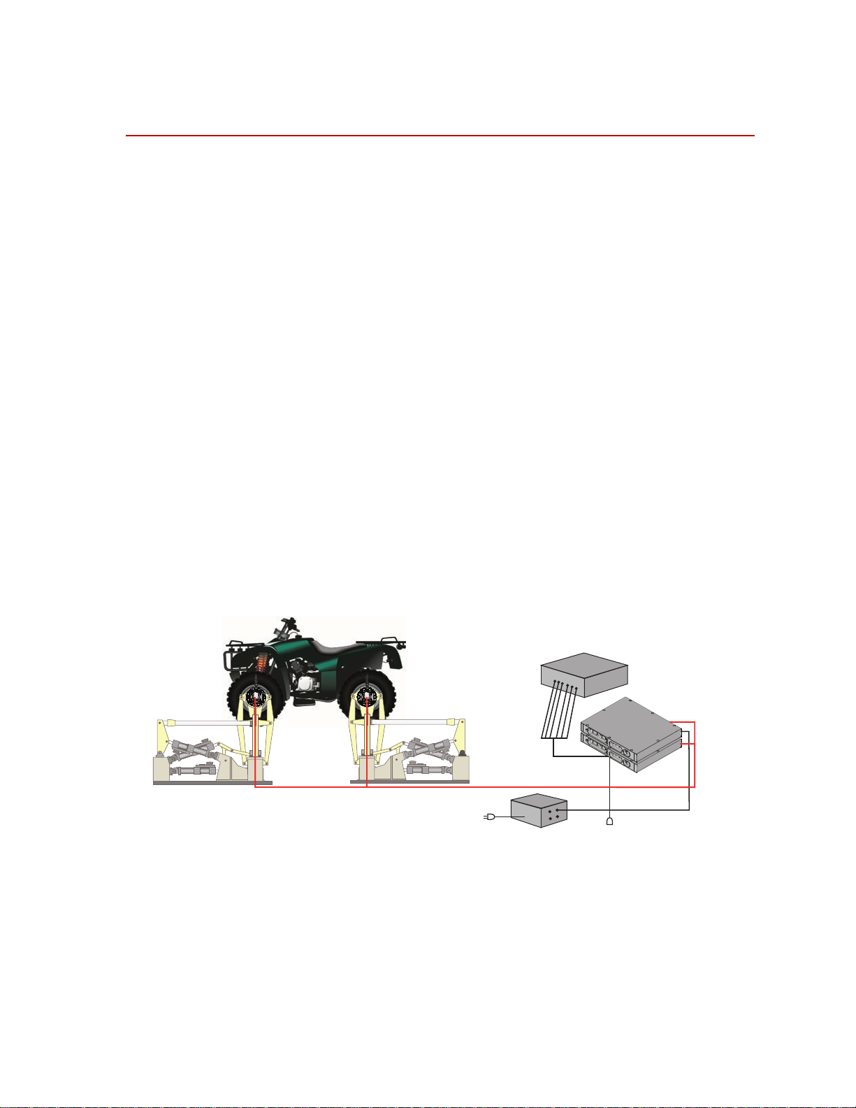
Non-Spinning Applications (Laboratory)
The SWIFT sensor can be fully integrated into the simulation process, since it is
an optimal feedback transducer for use with MTS Remote Parameter Control
(RPC) software. The transducer takes data at points where fixturing inputs are
located rather than at traditional instrumentation points along the vehicle’s
suspension. Using the SWIFT sensor saves you instrumentation time, and fewer
iterations are required to achieve good simulation accuracy.
Measuring spindle loads allows engineers to generate generic road profiles.
Generic road profiles are portable across various vehicle models, do not require
new test track load measurements for each vehicle, and eliminate additional
RLDA tasks.
Several of the six loads measured by the transducer directly correlate to the MTS
Model 329 Road Simulator inputs.
The same transducers used to collect road data can be mounted directly in the
wheel adapters of the MTS Model 329 Road Simulator. For durability testing, the
SWIFT sensor can be used for iterations within the RPC process. The SWIFT
sensor should then be removed for the durability cycles, to preserve its fatigue
life. It can be replaced by an adapter plate, available from MTS, to duplicate the
mass and center of gravity of the actual SWIFT sensor. If a SWIFT sensor is to be
used during full durability tests, we suggest using the titanium model, which has
a higher fatigue rating.
In a typical non-spinning application, a SWIFT sensor is mounted on a road
simulation test fixture, as shown in the following figure.
Non-Spinning Application (Laboratory Simulation)
®
SWIFT
Mini TI
Hardware Overview
17
Page 18

Non-Spinning Applications (Laboratory)
Design Features
Flexure isolation The SWIFT sensor has a very stiff outer ring and flexured beam isolation which
render it relatively insensitive to stiffness variations in matings with rims and
road simulator fixtures.
Flexure isolation minimizes thermal expansion stresses. With flexure isolation, if
the inner hub experiences thermal expansion the beams are allowed to expand
out, resulting in lower compressive stress on the beams.
Thermal stability The entire sensor is machined from a solid, specially forged billet of high
strength titanium or aluminum. The absence of bolted joints permits an efficient
transfer of heat across the sensor structure, minimizing temperature differentials
in the gaged area.
The transducer is designed to accommodate the high temperature environments
that occur during severe driving and braking events. Individual temperature
compensation of each strain gage bridge minimize temperature induced
variations in accuracy. Since minimal electronics reside on the SWIFT sensor, it
can easily tolerate high temperatures. The temperature rating for the SWIFT
sensor is 125° C (257° F) at the spindle hub.
Temperature compensation is done on each bridge for better performance in
transient or non-uniform temperature occurrences.
Low hysteresis The SWIFT sensor has very low hysteresis, since the sensing structure is
constructed with no bolted joints. Micro slippage in bolted joints contributes
most of the hysteresis in highly stressed structures. Hysteresis errors due to
micro-slip at joints can contribute to unresolvable compounding errors in
coordinate transformation of the rotating sensor.
Low noise The SWIFT sensor uses a slip ring for the transducer output signals. On-board
amplification of the transducer bridges minimizes any slip ring noise
contribution.
Low cross talk The advanced design of the SWIFT sensor means that it has very low cross talk.
The alignment of the sensing element is precision machined. This alignment is
critical to achieving minimum cross talk error between axes and minimum errors
in coordinate transformation (from a rotating to a non rotating coordinate
system). Any small amount of cross talk present is compensated by the TI.
Angle/Velocity
information
Angular position and angular velocity outputs are available from the TI when it is
used in the spinning mode with the encoder. In non-spinning applications,
accelerometers can be integrated into the transducer connector housing.
MTS does not supply any conditioning electronics for accelerometers. Ask your
MTS consultant for more information about this option.
Hardware Overview
18
SWIFT® Mini TI
Page 19
Coordinate System
Fx
Fy
Fz
Mz
Mx
My
Transducer
Interface
Output signals
±10 Volts
Angular
Position
Bridge
Outputs
S10-10
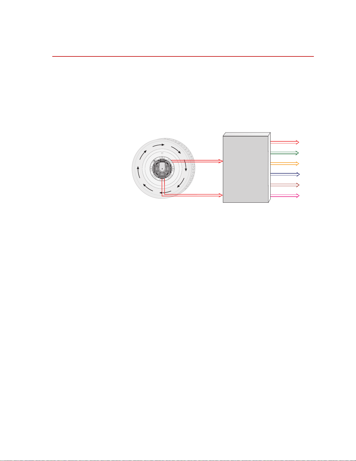
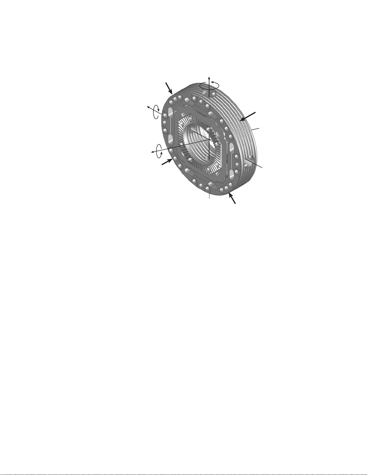
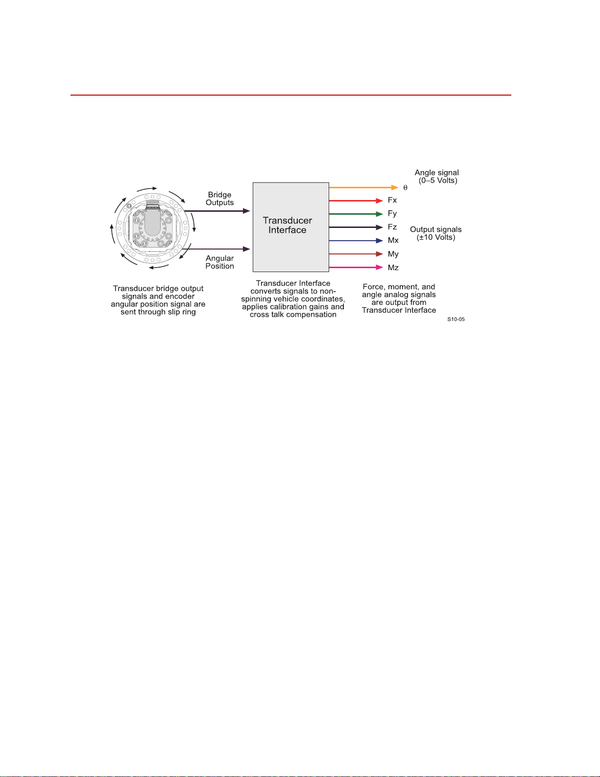
In the transducer, independent strain gage bridges measure forces and moments
about three orthogonal axes. The signals are amplified to improve the signal-tonoise ratio. An encoder signal measures angular position, which is used to
convert raw force and moment data from the rotating transducer to a vehiclebased coordinate system. The force, moment, and encoder information are sent to
the transducer interface (TI).
Coordinate System
The TI performs cross talk compensation and converts the rotating force and
moment data to a vehicle coordinate system. The result is six forces and moments
that are measured at the spindle: Fx, Fy, Fz, Mx, My, and Mz. If desired, the TI
can convert the forces and moments to represent a measurement that is offset
from the spindle along the y-axis. A seventh (angular) output is available for tire
uniformity information, angular position, or to determine wheel speed
(depending on the data acquisition configuration).
Normally, the moments are referenced to the center of the transducer but can be
offset to another location such as the center of the rim or tire patch.
SWIFT
®
Mini TI
Hardware Overview
19
Page 20
Coordinate System
+Fz
+Mz
+Fx
+Fy
S10-09
Forces Acting on Rim-side of Transducer
Hub Adapter
Mounting Side
Rim Flange
Mounting Side
+Mx
+My
The coordinate system shown below was originally loaded into the TI settings by
MTS. It uses the right-hand rule.
By default, the SWIFT coordinate system is transducer-based, with the origin
located at the center of the transducer . Positive loads are defined as applied to the
outer ring of the transducer.
• Vertical force (Fz) is positive up.
• Lateral force (Fy) is positive out of the vehicle.
• Longitudinal force (Fx) follows the right-hand rule, consistent with Fz and
Fy described above.
You can change to the MTS Model 329 Road Simulator convention (lateral load
into the vehicle is always positive) or to any coordinate system by changing the
polarities in the calibration file. The coordinate system can be moved along the yaxis by changing the y-axis parameter in the calibration file. For instructions on
how to change the coordinate system polarities and offset, see “Transducer
Interface Setup” on page 41.
Hardware Overview
20
SWIFT® Mini TI
Page 21

Specifications
Parameter Specification
Physical
Height
Width
Depth
Weight
Rack mounting kit
Environmental
Ambient temperature
Relative humidity
Protection
Transducer Interface
28 mm (1.100 in)
213 mm (8.375 in)
171 mm (6.750 in.)
*
0.907 kg (32 oz)
Optional
0–50 °C (32–122° F)
0 to 90%, non-condensing
IP64 (complete dust protection, projected water from all
directions)
Specifications
Power requirements
Input voltage
Fuses
Power Consumption
Angular velocity
Encoder limit
Processing limit
Time delay (encoder tick to main
output stable)
Transd ucer cable length
Analog outputs
Voltage
Capacitive load
Current
Resolution
10–28 VDC
Internal thermal, self-resetting
4 Watts maximum without transducer or encoder
6 Watts typical with transducer and encoder with 12 V DC
input.
2,200 rpm maximum
10,000 rpm maximum
150 µs (typical)
100 ft maximum
±10 V range† (force, moment, and angular velocity outputs)
0–5 V sawtooth (angle output)
0.01 µF maximum
2 mA maximum
16-bits
Communications
* Add 25.4 mm (1.0 in) for ground lugs.
† Standard from MTS. Other full scale voltages can be evaluated and may be provided at special
request.
®
SWIFT
Mini TI
USB 2.0
Hardware Overview
21
Page 22

Calibration
Calibration
Each transducer is calibrated by MTS before shipment. The transducer and TI
may be returned to MTS for repair and recalibration as required.
Calibration is performed at MTS on a special fixture that is capable of applying
multiple loads to the transducer. During calibration, raw signals are measured.
The calibration gains and cross talk compensation values are computed from this
raw data. These gains are recorded in a calibration file.
A unique calibration file is supplied for each transducer. The serial number of the
TI associated with the transducer is listed at the top of the calibration file. A label
with the serial number of the TI box (and the SWIFT sensor with which it was
originally calibrated) is attached to the back of each TI box.
The calibration file is loaded into the TI non-volatile memory by MTS before the
transducer is shipped. A copy of the file is also provided on a disk.
MTS verifies the calibration by applying loads to the transducer, measuring the
main outputs and checking for accuracy. Final calibration reports are provided
with each transducer.
Note For SWIFT transducers designed to operate with the previous generation
low-profile TI, shunt cables A and B must be connected prior to
performing a shunt check.
Shunt verification Shunt verification is good for verifying the SWIFT electrical system. A shunt
verification that fails should be investigated because the calibration will likely be
affected. However, a shunt passing does not guarantee the system load accuracy
so other checks should be done to verify load accuracy.
At the end of the calibration process, a shunt check is performed. During a shunt
check, a resistance is introduced into the bridge circuit. The difference between
the shunted and unshunted voltage is the delta shunt reference value for each
bridge. That value is saved in the calibration file, which is downloaded from a PC
or laptop computer and stored in non-volatile memory in the TI.
At any time afterward, pressing the Shunt button on the front of the TI causes
each of the strain gage bridges to be shunted in sequence, and the measured shunt
voltage (delta shunt measured value) is compared to the reference value.
An acceptable tolerance range is also loaded into the TI memory during system
calibration. One tolerance value is used for all bridges. This value is loaded as a
percentage of allowable deviation from the delta shunt values. For example, if the
FX1 bridge has a shunt delta reference value of –3.93, and the tolerance is set at 2
(percent), the acceptable range for the measured value would be –3.85 to –4.01.
Hardware Overview
22
SWIFT® Mini TI
Page 23

Calibration
When you press the Shunt button, the associated Shunt indicators toggle while
the shunt is in progress. As the TI automatically switches through the series of
bridges, it verifies that the outputs are within the accepted tolerance range. If all
bridge shunt values fall within the tolerance range, the Shunt indicators on the
front panel will go off (after several seconds). If any bridge fails the shunt test,
the red, fail indicator lights, indicating that the shunt calibration has failed. The
fail indicator remains lit until a shunt check passes or until you cycle power off
and on. Use the TI2STATUS utility to get more detailed information about the
shunt failure.
ShuntTolerance=2
FX1ShuntDeltaRef=-1.379
FX2ShuntDeltaRef=-1.386
FY1ShuntDeltaRef=-1.381
FY2ShuntDeltaRef=-1.378
FY3ShuntDeltaRef=-1.382
FY4ShuntDeltaRef=-1.381
FZ1ShuntDeltaRef=-1.380
FZ2ShuntDeltaRef=-1.380
FX1ShuntDeltaMeas=-1.378
FX2ShuntDeltaMeas=-1.386
FY1ShuntDeltaMeas=-1.380
FY2ShuntDeltaMeas=-1.379
FY3ShuntDeltaMeas=-1.382
FY4ShuntDeltaMeas=-1.382
FZ1ShuntDeltaMeas=-1.385
FZ2ShuntDeltaMeas=-1.382
Manual shunt
verification
Example of Calibration File Shunt Data
The above example shows shunt data from the calibration file. This data can be
transferred, using the TI2XFER program, from the transducer interface memory
to a computer or from a computer to the transducer interface memory. Note that
items marked ShuntDeltaMeas are uploaded from memory, but not downloaded
from the computer.
For more information on TI2XFER, see the chapter, “Software Utilities”.
You can check the system at any time by pressing the Shunt switch (described
earlier). The shunt verification checks a portion of the system by applying an
electrical offset at the input. Shunt verification can be used as a troubleshooting
tool; failing the shunt verification raises the possibility the system is not
calibrated. You can set the tolerance values for each TI by editing the calibration
file. For instructions, see “Transducer Interface Setup” on page 41.
SWIFT
®
Mini TI
Hardware Overview
23
Page 24
Transducer Interface
or
Angular Velocity
signal (+/- 10 V)
Transducer Interface
The TI performs cross talk compensation, transforms the loads from a rotating to
a non-rotating coordinate system, and produces an analog output signal suitable
for most data recorders.
Cross talk
compensation
Cross talk occurs when a force is applied to one axis, but a non-real force is
measured on another axis. The SWIFT sensor design has very low inherent cross
talk. The TI compensates for cross talk by subtracting cross talk values measured
during calibration.
Signal conditioning The TI is specifically designed to be used for both spinning and non-spinning
applications. The TI performs signal conditioning and communications
functions. The output from the TI is a high-level signal suitable for input into a
multichannel data recorder or an MTS Automated Site Controller (ASC).
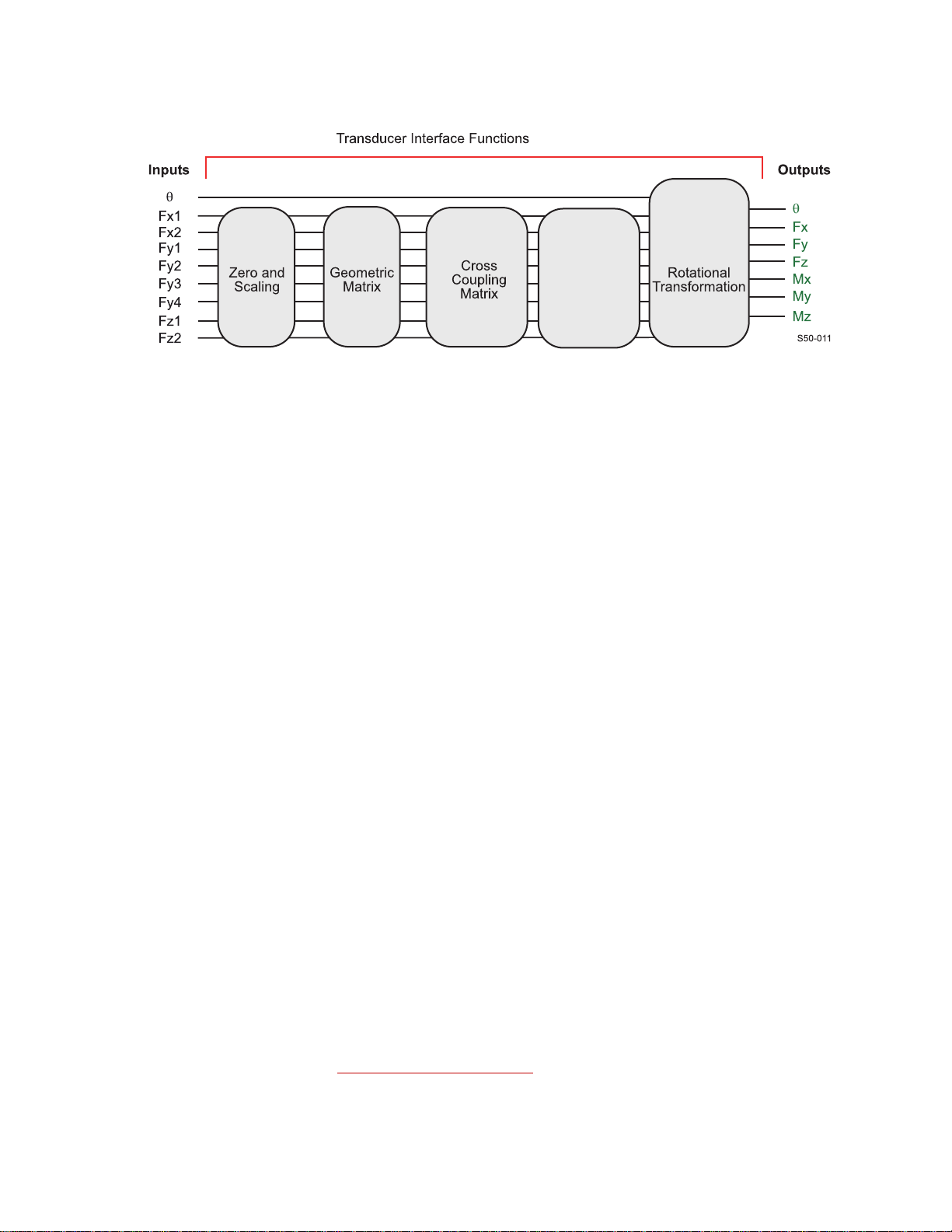
The TI transforms eight inputs (amplified bridge signals) into three forces and
three moments by the following process:
• Applying a zero offset and scaling the signals
• Using a geometric matrix to transform the signals into three forces and three
moments in the transducer reference frame
• Using a cross-coupling matrix calculation to scale and sum the individual
signals into each output
• Using an offset matrix to shift the coordinate system along the y-axis
• In spinning applications, using a rotational transformation to put the forces
and moments into a stationary reference frame
Hardware Overview
24
SWIFT® Mini TI
Page 25
Transducer Interface
Coordinate
System
Oset
Matrix
The TI conditions the transducer signals, producing seven analog output signals
proportional to the following values:
• Longitudinal force (Fx)
• Lateral force (Fy)
• Vertical force (Fz)
• Overturning moment (Mx)
• Driving/Braking moment (My)
• Steering moment (Mz)
• Angle (θ) or Angular Velocity (ω)
Analog signals The force, moment, and angular velocity signals are output from the TI in the
1
form of ±10 V
acquisition systems.
The angle output is an analog voltage that is proportional to angular position. At
0° the output is 0 V. At 360°, the output is 5 V.
full scale analog signals. These signals can be used by most data
SWIFT
®
Mini TI
1. Standard from MTS. Other full-scale output voltages can be evaluated and may be
provided at special request.
Hardware Overview
25
Page 26
Transducer Interface
0 360°
5V
0° 360°
q
Angle
Output
1 rev = 360°
S20-10
The angle output for a tire rotating at constant velocity can be represented by the
following illustration:
Although you may not routinely use it, the angle output information is available
for tasks such as tire uniformity testing and troubleshooting.
If using the sawtooth angle output for analysis, care should be taken when setting
the data acquisition to avoid filter-induced ringing or attenuation of the sawtooth
output.
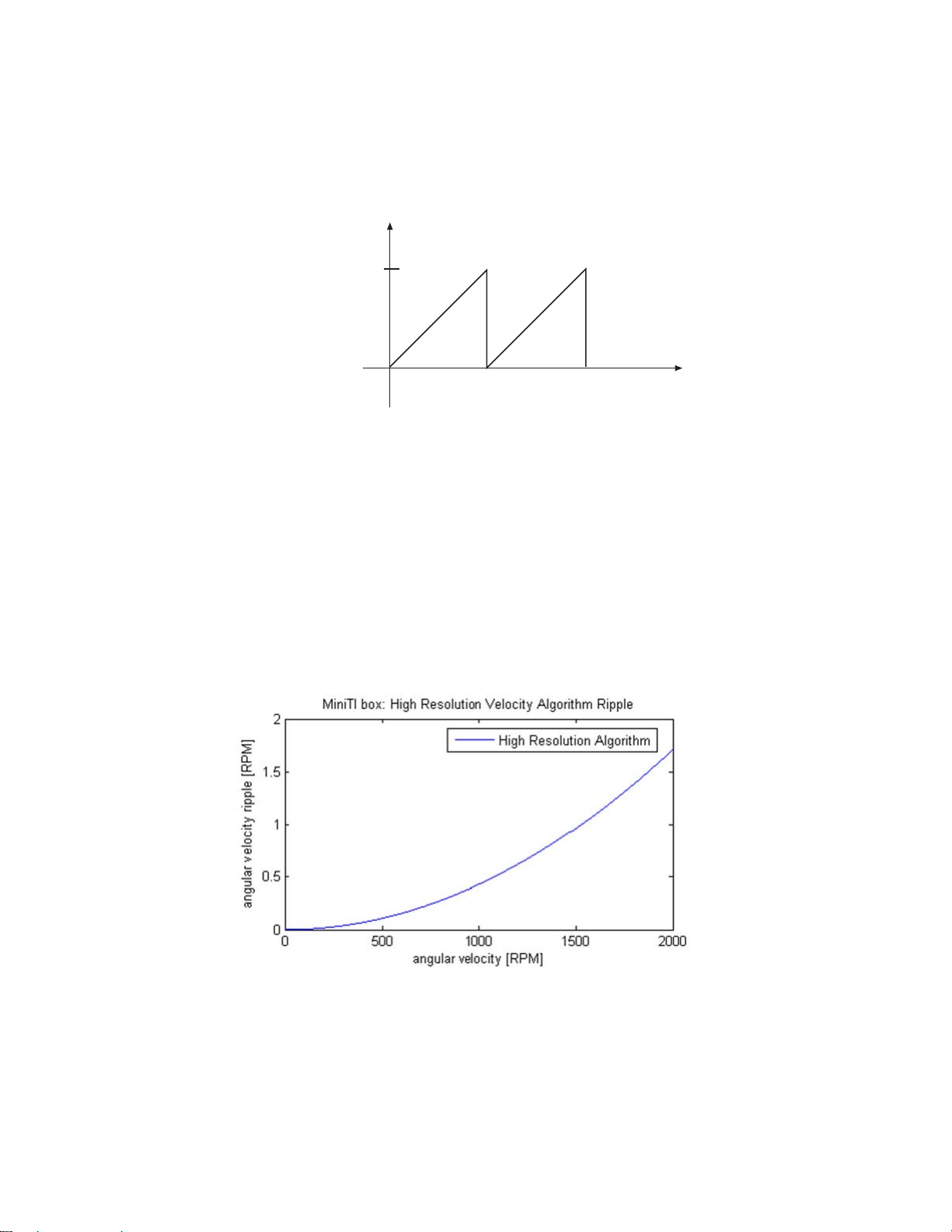
High-Resolution
Velocity Algorithm
The Mini TI has two algorithms for calculating angular velocity. The high
resolution algorithm provides a much cleaner signal, but requires a minimum
Mini TI FPGA version of 15. For the high resolution algorithm, the plot below
shows the expected ripple of the angular velocity signal as a function of actual
angular velocity.
The low resolution velocity algorithm produces significantly larger ripples on the
angular velocity signal. These ripples can be reduced by enabling a filter at the
input of data acquisition system. For more information on the angular velocity
output option, contact MTS.
Communications The TI uses USB 2.0 for communication. The MTS supplied USB drivers must
be installed on each computer you connect to the TI.
Hardware Overview
26
SWIFT® Mini TI
Page 27

TI Front Panel
Power button and Indicator
and Fail Indicator
Shunt button
and Indicators
Zero button and
Indicators
J5 USB
Connector
J4 I/O
Connector
Transducer Interface
Transducer Interface Front Panel
Power button and
Indicator
Shunt button and
indicators
Zero button and
indicators
The power button turns power on and off. Pressing and holding the button turns
on power and initializes the TI. During initialization, all indicators turn on
momentarily. When initialization is complete, all indicators will turn off with the
exception of the green Power indicator.
Pressing this button performs a shunt calibration (shunt cal) of the transducer.
You do not need to hold the button in continuously, only until the Shunt
indicators light up (indicating that the TI has started the shunt cal). The two
indicators will alternately toggle on and off as the TI sequences through the shunt
calibration of each bridge.
Before you perform a shunt cal, check that the appropriate shunt reference value
and error tolerance have been downloaded (these values are normally loaded
during system calibration.)
A shunt calibration will determine the current delta values by measuring the
bridges unshunted and shunted values, and then compare these values to the
previously loaded reference values.
If the measured values are outside of an acceptable tolerance the red status
indicator under the Power indicator with light.
Note The state of the shunt cal check is cleared at power-up, so the shunt cal
should be performed when the system installation is in question.
The zero button is used to zero the transducer inputs. When you press the button,
the TI executes the ZeroAlgorithm that you specify in the calibration file (see
“Calibration File Elements” on page 45).
J5 USB connector The USB connector is a standard USB 2.0 type B connector for connection to a
laptop or PC with the correct drivers installed.
J4 I/O connector Not used at this time.
®
SWIFT
Mini TI
Hardware Overview
27
Page 28

Transducer Interface
J3 Transducer
Connector
J2 Output
Connector
J1 Power
Connector
TI Rear Panel
Transducer Interface Rear Panel
J1 Power connector Connect a power cable from the external power source.
J2 Output connector The J2 Output connector provides the conditioned sensor outputs that can be
connected to a data acquisition or test control system.
J3 Transducer
connector
Transducers Designed
to Operate with a Low-
Profile TI but Using a
Mini TI
Connect the data cable from the transducer slip ring to the Transducer Connector.
For SWIFT transducers designed to operate with a Low-Profile TI but are using
the Mini TI, an adapter cable is needed; MTS part number 100224052. The
transducer and shunt cables are connected to one end of the adapter cable and the
other end is connected to J3 of the Mini TI.
28
Hardware Overview
SWIFT® Mini TI
Page 29

Software Utilities
Contents Introduction 30
TI2STATUS - Transducer Interface Status 31
TI2XFER - Transducer Interface Transfer 33
TI2SHUNT - Transducer Interface Shunt 35
Error Messages 38
SWIFT® Mini TI
Software Utilities
29
Page 30

Introduction
Introduction
The SWIFT utility programs in this distribution are for Win32 Operating
Systems (Windows 2000 and XP). They are designed to be run from the
Command Prompt or MSDOS Shell. However, it is possible to create a shortcut
to run the programs. If launched from a shortcut the application window may
close immediately when the application terminates making it impossible to see
any error messages. The Command Prompt application is usually found in
Start–>Programs–>Accessories but the actual location depends on the version
of your operating system.
To run a SWIFT utility program:
1. Copy it to your computer. For example, create the folder
the executables (*.exe) to that folder.
1
2. Launch Command Prompt
3. Change the working directory to where you copied the executables:
This step can be eliminated if you set up the PATH environment variable to
include the directory where you copied the SWIFT utility executables.
4. Type the name of a SWIFT utility program providing the necessary
command line arguments, for example:
from the TI box. Then select the desired function, for example:
to upload settings from the TI box. If no command line arguments are
provided the program will display a simple help message. This is helpful if
you forget the order of the command line arguments.
.
ti2xfer to transfer settings to or
C:\bin and drag
Choice 1
cd bin.
2
Software Utilities
30
1. You may want to change the layout properties for the Command Prompt
window to display a larger area or to increase the screen buffer size. Within
Command Prompt, select Properties and the Layout tab to modify the
screen buffer size or window size.
2. In Windows 2000 and Windows XP, the environment variables can be
changed at Start–>Settings–>Control Panel–>System. Click on the
Advanced tab, and the Environment Variables button. The path is a
system variable. Adding
the end of the string will cause Command Prompt to search that directory
for applications.
;c:\bin, or whatever directory name you used, to
SWIFT® Mini TI
Page 31

TI2STATUS - Transducer Interface Status
TI2STATUS - Transducer Interface Status
This program gets status information from the SWIFT Transducer Interface (TI)
when the TI has encountered a problem and the red failed indicator is lit. Y ou can
use this program to easily interpr et the er ror. For certain errors this program may
provide additional information.
Syntax ti2status
The following is an example of the ti2status command report:
Example
C:\bin>ti2status
SWIFT Mini TI status (Version 1.3)
Fatal error: NONE
Boot Loader version: 1
FPGA version: 10
Firmware version: 24
Zero: Good
Fx1 Shunt: Good
Fx2 Shunt: Good
Fy1 Shunt: Good
Fy2 Shunt: Good
Fy3 Shunt: Good
Fy4 Shunt: Good
Fz1 Shunt: Good
Fz2 Shunt: Good
Calibration data is: Good
Unit serial number: 02036413
Description of TI2STATUS Indications
Fatal Error: Provides an indication that the CPU is unable to run. The message indicates the
possible reason (see, “Error Messages,” on page 38 for a list of the possible
errors).
Boot Loader version: The boot loader is a program that verifies that the main program is complete. The
version number is a reference for use by service personnel (see, “Error
Messages,” on page 38 for a list of the possible errors).
FPGA version: Identifies the version of the functions programmed in the field programmable
gate array. The version number is a reference for use by service personnel.
Firmware Version: Displays the version of the software installed in the TI. This software is stored in
flash memory and if needed can be upgraded in the field by an MTS service
engineer.
SWIFT
®
Mini TI
Software Utilities
31
Page 32

TI2STATUS - Transducer Interface Status
Zero: Indicates whether the transducer zeroing was successful or not (see, “Error
Messages,” on page 38 for a list of the possible errors).
F## Shunt: Indicates the status of shunt test for each bridge (see, “Error Messages,” on page
38 for a list of the possible errors).
Calibration data is: Indicates that the TI calibration data passed a data consistency check. The TI is
calibrated by itself, before system calibration is performed. this allows a TI to be
swapped without significantly affecting system calibration. For more information
see, “Error Messages,” on page 38 for a list of the possible errors).
Unit serial number: Displays the serial number of the TI box.
Software Utilities
32
SWIFT® Mini TI
Page 33

TI2XFER - Transducer Interface Transfer
TI2XFER - Transducer Interface Transfer
This program is used to read the current settings in the TI and save them to the
computer (upload) or write the values from a calibration file on the computer to a
TI (download).
Syntax ti2xfer
The following is an example of the ti2xfer command:
Example
C:\bin>ti2xfer
SWIFT Mini TI transfer (Version 1.0)
Upload and download settings
0...Exit
1...Upload settings from TI box
2...Download settings to TI box
Choice? 1
Filename? sample.cal
0...Exit
1...Upload settings from TI box
2...Download settings to TI box
Choice? 0
File Format The file used with commands contains a header and version number, and a list of
parameters. Transducer calibrations can be uploaded and saved individually. If a
test needs to be rerun at a later date but the original transducer is not available,
another transducer can be used by downloading its calibration information.
Following the header is a list of parameter settings. The syntax is:
ParamName=ParamValue
The following rules apply:
Tabs and spaces are allowed.
The parameters can occur in any order.
Names are case insensitive. If a parameter name is not recognized, a
warning will be reported.
SWIFT
®
Mini TI
If an error causes the program to abort while downloading, any parameters
prior to the error will have been successfully downloaded because
parameters are downloaded as they are read. Only those parameters in the
file are downloaded. Parameters not in the file are unchanged.
Software Utilities
33
Page 34

TI2XFER - Transducer Interface Transfer
CAUTION
CAUTION
Make important files (such as those containing calibration data) read-only
after uploading.
If not protected, important data may get overwritten.
Make important files read-only. Make backups of important data.
Check force and moment output signals after downloading new settings.
Downloading new settings may affect Transducer Interface outputs.
After downloading new settings, force and moment output signals should be
monitored to check basic system operation.
More about TI2XFER
files
The calibration files created by TI2XFER are plain text files that can be read by
Microsoft Notepad or WordPad (see the example calibration file on page 45). In
general, use a common extension such as “.cal” to help identify the files, but that
is not required. The settings files contain both configuration settings and
calibration settings. As a general rule parameters that begin with K are
calibration gains and should not be edited.
Whenever downloading settings, make sure the file is for the transducer
connected to the SWIFT Transducer Interface. Usually the filename for the
settings contains the serial number for the transducer. If settings for one
transducer are used with another they will not be accurate. Because the TI is
calibrated by itself, calibration settings for a given transducer can be used with
any TI, however, some calibration methodologies require the transducer, cable
and TI to be used as a calibration set (end-to-end calibration).
The serial number in the TI2XFER settings file is the serial number of the TI that
the settings were first uploaded from.
The bridge and angle zero values will change whenever a zero is activated by
pressing the TI front panel Zero button. Therefore, after a zero is performed the
zero values uploaded will not match those downloaded.
Software Utilities
34
SWIFT® Mini TI
Page 35

TI2SHUNT - Transducer Interface Shunt
TI2SHUNT - Transducer Interface Shunt
This program is a utility with various functions related to shunts. The SWIFT
system includes the ability to connect a shunt resistor across each of the resistive
bridges in the transducer. This shunt function can be used as a simple verification
that the SWIFT system is working normally. Shunt verification activates the
shunts and compares the results to those recorded during calibration. While this
does not guarantee the transducer is still in calibration, it provides some level of
confidence it is working normally. If the shunt results differ significantly from
those recorded during calibration the SWIFT system should be evaluated for
possible problems.
Syntax ti2shunt
Example
C:\bin>ti2shunt
SWIFT Mini TI Shunt (Version 1.0)
0...Exit
1...Read current shunt status
2...Set the TI shunt tolerance
3...Scan inputs with shunts
4...Command a shunt cal
5...Set references to last measured
Enter choice: 1
The Shunt Main Menu options are described in the following paragraphs.
Option 0 Use this option to exit the program.
Option 1 Use this option to read the last measured shunt values, the reference values, and
the shunt status.
Note The shunt status is not maintained over power cycles, so it is only valid if
the shunt is executed after power is applied. Refer to, “Error Messages,”
on page 38.
The following is typical of what is displayed when this selection is made:
Enter choice: 1
FX1 Ref: 0.854 Measured: 0.854 Status: Good
FX2 Ref: 0.855 Measured: 0.855 Status: Good
FY1 Ref: 0.857 Measured: 0.857 Status: Good
FY2 Ref: 0.858 Measured: 0.857 Status: Good
FY3 Ref: 0.856 Measured: 0.856 Status: Good
FY4 Ref: 0.857 Measured: 0.856 Status: Good
FZ1 Ref: 0.856 Measured: 0.856 Status: Good
FZ2 Ref: 0.856 Measured: 0.855 Status: Good
SWIFT
®
Mini TI
Software Utilities
35
Page 36

TI2SHUNT - Transducer Interface Shunt
Option 2 Use this to set the shunt tolerance. When selected, the following is displayed:
Enter choice: 2
The current shunt tolerance is 2%
Enter new shunt tolerance in percent?
Option 3 Use this option to apply a shunt to each bridge individually, read the output of the
bridge, compare the result with the value stored in the Transducer Interface and
display the difference each bridge. See the table on the next page. The shaded
fields are the bridge being shunted. The actual sequence depends on the
transducer wiring. Note that this option does not update the shunt measured
values or error status.
Enter choice: 3
FX1 FX2 FY1 FY2 FY3 FY4 FZ1 FZ2
Unshunted: 0.00050 0.00042 0.00017 -0.00050 -0.00005 -0.00033 -0.00025 0.00000
Shunted1:
Differ1:
Unshunted: 0.00017 0.00008 -0.00050 -0.00117 0.00062 -0.00033 0.00008 0.00000
Shunted2: 0.00050 0.00042
Differ2: 0.00033 0.00033
Unshunted: 0.00050 0.00008 0.00017 -0.00050 -0.00005 -0.00000 0.00042 0.00000
Shunted3: 0.00050 0.00008 -0.00017 -0.00017 0.00062 -0.00000
Differ3: 0.00000 0.00000 -0.00033 0.00033 0.00067 0.00000
Unshunted: 0.00017 0.00008 -0.00050 -0.00084 -0.00005 -0.00000 0.00075 -0.00033
Shunted4: 0.00050 0.00008 -0.00017
Differ4: 0.00033 0.00000 0.00033
Unshunted: 0.00084 -0.00025 -0.00017 -0.00017 0.00062 -0.00033 0.00008 0.00033
Shunted5: 0.00050
Differ5: -0.00033
Unshunted: 0.00050 0.00008 0.00017 -0.00050
Shunted6: -0.00017 0.00042 0.00017 -0.00017
Differ6: -0.00067 0.00033 0.00000 0.00033
Unshunted: 0.00050 0.00042 -0.00017 -0.00084 -0.00005 -0.00033 0.00008
Shunted7: 0.00084 0.00008 0.00050 -0.00050 -0.00005 -0.00033 0.00008
Differ7: 0.00033 -0.00033 0.00067 0.00033 0.00000 0.00000 0.00000
Unshunted: 0.00017 0.00008 0.00017 -0.00084 -0.00005
Shunted8: -0.00017 0.00008 0.00017 -0.00050 0.00028
Differ8: -0.00033 0.00000 0.00000 0.00033 0.00033
0.85475 0.00008 -0.00017 -0.00050 0.00028 -0.00033 -0.00025 0.00000
0.85424 -0.00033 -0.00033 0.00000 0.00033 0.00000 0.00000 0.00000
0.85675 -0.00117 0.00028 -0.00000 0.00008 0.00000
0.85725 0.00100 -0.00033 0.00033 0.00000 0.00000
0.85620 -0.00033
0.85579 -0.00033
0.85747 -0.00005 -0.00033 0.00008 0.00000
0.85831 0.00000 -0.00033 -0.00067 0.00033
0.85557 -0.00017 -0.00050 -0.00005 -0.00033 0.00042 0.00000
0.85582 0.00000 -0.00033 -0.00067 0.00000 0.00033 -0.00033
-0.00038 -0.00000 0.00008 0.00033
0.85614 -0.00033 -0.00025 -0.00033
0.85653 -0.00033 -0.00033 -0.00067
0.00000
0.85510
0.85510
-0.00000 0.00008 0.00067
0.85610 0.00008 0.00000
0.85610 0.00000 -0.00067
Software Utilities
36
Option 4 Use this option to command a Shunt Cal in the Transducer Interface. This is the
same as pressing the Shunt button on the front panel of the TI. A period is
displayed on the screen for every change in the shunt state. This gives you a
quick view of the progress.
SWIFT® Mini TI
Page 37

TI2SHUNT - Transducer Interface Shunt
Option 5 A valid shunt calibration should be performed prior to executing this command.
This option allows an easy means of setting the Shunt Calibration Reference
values after calibration. This is normally done as part of calibration and should
not be done during normal use. After this option has executed, uploads will
contain the new shunt reference values.
Note This menu choi ce should only be used by qualified service personnel.
SWIFT
®
Mini TI
Software Utilities
37
Page 38

Error Messages
Error Messages
When a SWIFT utility encounters an error, the red failed indicator on the TI front
panel lights. Run the TI2STATUS program to identify the cause of the error.
Following is a list of possible error messages:
• Fatal Errors
NONE
Failed command port initialize
Failed I2C (integrated-integrated-circuit) initialize
Failed non-volatile memory initialize
Failed compute module initialize
Failed ADC (analog-to-digital converter) initialize
Failed DAC (digital-to-analog converter) initialize
Failed calibration multiplexer initialize
Failed while reading I2C
Failed timer initialize
Failed interrupt initialize
Failed encoder initialize
Failed zero module initialize
Failed shunt module initialize
Unrecognized failure code – This error could be due to hardware
failures or software bug.
• Boot Loader – The boot loader runs when you turn on power. This line
displays the version number if boot was successful.
Error, boot loader has not run – This occurs if the CPU is not
running.
Error, the boot loader has not finished – Something prevented the
CPU from completing booting the main program.
Error, the boot loader found a bad Flash CRC (cyclic redundancy
check) – This error is likely due to a corrupted Flash program.
Software Utilities
38
Computed CRC =
Flash CRC =
Error, unrecognized boot loader error code of: – Possibly corrupted
memory; communications or the version of TI2STATUS is not
compatible with the firmware.
SWIFT® Mini TI
Page 39

• Zero
Good – no problems detected
Bad Angle Offset – The change in angle was not 90°, ±2°.
Direction Change – The direction of 90° increments reversed.
• Shunt
Good – no problems were detected.
Reference Bad – The shunt reference is out of range.
Shunted Bad – A shunt value does not match the shunt reference.
Unshunted Bad – While shunting one bridge another bridge output
unexpectedly changed.
• Calibration Data is:
Good – No problems were detected.
Bad – The unit has not been calibrated or the calibration memory is
corrupted.
Error Messages
SWIFT
®
Mini TI
Software Utilities
39
Page 40

Error Messages
Software Utilities
40
SWIFT® Mini TI
Page 41

Transducer Interface Setup
Overview Two different software configurations are used by the TI, depending on whether
you will be using the SWIFT sensor on the test track (typical for spinning
application) or in the laboratory (typical for non-spinning or fixed application).
Angular transformation is required on the test track only. If you are using the
same transducer and TI for data collection on the test track and simulation testing
in the laboratory, you must change the software configuration in the TI when you
change testing modes.
Contents USB Driver Installation 42
Select a Zero Method 44
Calibration File Elements 45
Upload the Calibration File 47
Edit the Calibration File 48
Download the Calibration File 52
SWIFT® Mini TI
Transducer Interface Setup
41
Page 42

USB Driver Installation
USB Driver Installation
Two USB 2.0 drivers must be installed to recognize the Transducer Interface.
Perform the following procedure to install these drivers on a laptop or desktop
computer that does not already have these drivers installed.
Important Do not allow Windows to search for or choose the drivers for you.
Always direct Windows to the path containing the Mini TI USB
drivers.
1. Copy the Mini TI USB drivers from the Utilities CD provided to your hard
drive.
2. Push and hold the Power button on the Mini TI. Release the button when
the Power indicator lights.
All the indicators on the Mini TI will light briefly then go out leaving only
the Power indicator lit.
3. Connect the USB cable between the computer and the Mini TI.
The Found New Hardware Wizard will launch. On the screen that
displays, select the No, not this time radio button (see the next figure).
Transducer Interface Setup
42
SWIFT® Mini TI
Page 43

USB Driver Installation
4. On the next window, select the Install from a list or specific location
(Advanced) radio button.
5. If you copied the driver files from the CD to your hard drive, use the
browser to direct the wizard to the location where you copied the files as
shown in the next figure.
6. Click Next to install the loader for the MTS SWIFT TI Interface
7. When the installation is complete, click Finish on the window that displays.
SWIFT
®
Mini TI
8. Another Found New Hardware Wizard will display.
Repeat Steps 4 through 7 to install the MTS SWIFT TI Interface driver for
the TI Interface.
9. If prompted by Windows, restart your computer to activate the new settings.
Transducer Interface Setup
43
Page 44

Select a Zero Method
Select a Zero Method
Before you install a transducer and zero it, you must configure the transducer
interface (TI) for the appropriate operating mode.
Equipment required You wil l need:
• A laptop computer (at test track) or desktop PC with Window 2000 or XP
operating system.
• A USB 2.0 communication cable with type A to type B connectors.
• SWIFT Transducer Interface Utilities diskette.
• Some experience with DOS commands and text editors.
Modes There are two separate modes for using the transducer interface. The mode you
choose depends on whether you will use the transducer in a spinning (test track)
application (AngleMode = 0) or non-spinning (road simulator) application
(AngleMode = 1).
If you are using the same transducer with a road simulator that you used
previously on the test track, or vice versa you must download the proper
calibration file and re-zero the transducer.
In either mode, the zero button on the front panel of the TI is used to zero the
angle and balance the bridges.
What you need to do To change the angle mode used by the TI:
1. Copy the original calibration file from the CD or diskette that came with the
transducer to the computer.
Note A separate calibration file was created at the factory for each transducer.
In the next steps, note the serial number of the transducer identified in
the calibration file and the serial number of the TI box that the file was
downloaded to. This information will be used later.
2. Edit the calibration file to select appropriate angle mode: 0 = spinning,
1 = non-spinning (fixed).
3. Download the modified calibration file from the computer to the TI box.
4. Repeat the process for all of the transducers.
These steps are described in detail in the following sections.
Transducer Interface Setup
44
SWIFT® Mini TI
Page 45

Calibration File Elements
The following figure shows some elements of the calibration file:
Select a Zero Method
SWIFT
®
Mini TI
Typical Calibration File
Transducer Interface Setup
45
Page 46

Select a Zero Method
Items you may edit • OutputPolarities—defines the polarities of the six outputs. Change these
only if your application requires different polarities from those identified on
the transducer label.
• AngleMode—selects the mode used for determining the encoder sine and
cosine.
• AngleFixed—used for non-spinning applications.
• AngleOffset— used for spinning applications. Normally you do not need to
change this value.
• EncoderSize—defines the size of the encoder.
• Y-Axis Offset—shifts the output coordinate system along the y-axis
• Output 7 signal—selects Angle of Angular Velocity for analog output
channel 7.
• VelocityFullscale—sets the 10 V fullscale value for the Angular Velocity
output.
Transducer Interface Setup
46
SWIFT® Mini TI
Page 47

Upload the Calibration File
A unique calibration file was loaded into the TI memory by MTS before the
transducer and transducer interface were shipped. Use the program TI2XFER to
retrieve the calibration file.
1. Connect a USB cable from the laptop computer or PC to the TI.
Note Ensure the proper USB 2.0 drivers are installed on the laptop or PC.
Refer to, “USB Driver Installation,” on page 42, as necessary
2. Insert the SWIFT Transducer Interface Utilities CD or diskette into the
laptop computer or PC.
3. Run the program TI2XFER.
4. Enter 1 at the prompt to upload the calibration file. (See the illustration
below.)
5. Enter a file name.
6. TI2XFER will prompt you when the file has uploaded.
Upload the Calibration File
SWIFT Mini TI transfer (Version 1.0)
Upload and download settings
0...Exit
1...Upload settings from TI box
2...Download settings to TI box
Choice? 1
Filename? sample.cal
0...Exit
1...Upload settings from TI box
2...Download settings to TI box
Choice? 0
7. Enter 0 at the prompt to exit the program.
SWIFT
®
Mini TI
Transducer Interface Setup
47
Page 48

Edit the Calibration File
CAUTION
Edit the Calibration File
The calibration file contains offset values for all of the bridge outputs.
Changing any values other than those listed in the following procedure will
cause your calibration file to be incorrect.
Take care not to change any values except those listed in the following procedure.
If your calibration file is incorrectly changed, reload the original file from the
diskette provided by MTS.
1. Open the calibration file using a text editor.
Typically two calibration files are provided with each transducer: one for
spinning applications and one for non-spinning (fixed) applications.
The spinning application files are usually names in the format
<transducer serial number>s.cal.
The non-spinning (fixed) application files are usually names in the format
<transducer serial number>f.cal.
Transducer Interface Setup
48
SWIFT® Mini TI
Page 49

Output Polarity Value
S20-34
Front
Fz
Up
Fy
Out
Fx
Aft
Fz
Up
Fx
Fore
Fy
Out
S20-35
Front
Fy
In
Fz
Up
Fx
Aft
Fy
In
Fx
Fore
Fz
Up
S20-41
Front
Fx
Aft
Fy
In
Fz
Up
Fx
Aft
Fy
Out
Fz
Up
Edit the Calibration File
2. If necessary, edit the value for Polarity (see the table below).
The polarities that match the coordinate icon on the transducer are:
Fx=0
Fy=0
Fz=0
Mx=1
My=0
Mz=1
Example Output Polarities
Description
Direction of Positive
output from load on tire
when mounted on left
hand side of the vehicle.
Direction of Positive
output from load on tire
when mounted on right
hand side of the vehicle.
OutputPolarities = 40 Standard Setting from
MTS. Matches the axis
orientation on the front
cover of the SWIFT.
OutputPolarities = 5 Common setting to
alter the axis for-aft and
in-out lateral axis.
OutputPolarities (left side) = 1
OutputPolarities (right side) = 0
Common setting for
vehicle coordinate
matching between the
two sides of the
vehicle.
+Fx = fore
+Fy = out from car, left
+Fz = up
+Mx, +My+, +Mz =
Right-hand rule about
Force axis
+Fx = aft
+Fy = into car, right
+Fz = up
+Mx, +My, +Mz =
Right-hand rule about
Force axis.
+Fx = aft
+Fy = into car, right
+Fz = up
+Mx, +My, +Mz =
Right-hand rule about
Force axis.
+Fx = aft
+Fy = out from car, right
+Fz = up
+Mx, +My , +Mz = Right-
hand rule about Force
axis
+Fx = fore
+Fy = into car, left
+Fz = up
+Mx, +My , +Mz = Right-
hand rule about Force
axis.
+Fx = aft
+Fy = out from car, right
+Fz = up
+Mx, +My , +Mz = Right-
hand rule about Force
axis.
SWIFT
®
Mini TI
Transducer Interface Setup
49
Page 50

Edit the Calibration File
3. If desired, set up the coordinate system offset.
In the following figure, Fx, Fy, Fz is the original default coordinate system
location. F’x, F’y , F’z is the output coordinate system with a y-axis negative
offset. The offset is entered in the calibration file:
// Coordinate system offset in mm.
// A non-zero value will shift the location of the output
// coordinate system along the transducer's y-axis. A
// positive value will shift the coordinate system from
// the center of the transducer body in the positive
// y-axis direction by the amount specified.
YAxisOffset = [user entered offset]
If the offset in this example is 100mm, the calibration file parameter would
be entered as:
YAxisOffset = -100.0
Transducer Interface Setup
50
4. Perform this step for spinning application. For non-spinning applications,
skip to Step 5.
A. Verify the value for AngleMode.
Set the AngleMode=0
In this mode, the encoder pulses are summed in with the offset. At the
end of the process the value in the TI internal memory and is used to
perform the rotational transformation of the output signals.
SWIFT® Mini TI
Page 51

Edit the Calibration File
B. The AngleOffset value is used when you are operating in encoder
mode (spinning applications). This value is summed with the encoder
output count. At the end of the process the value in the TI internal
memory and used when the angle mode is set to 0 (encoder). Negative
angles are converted to their positive equivalent so that the readback
value range is 0–360°.
The AngleOffset value is calculated by the TI during the zero process.
At the end of the process it is written to the calibration file.
There is no need to change this calculated value.
C. Verify that EncoderSize=2048.
D. If applicable, enter the Angular Velocity full scale.
The Angular Velocity full scale is entered in the calibration file:
// Velocity output scaling (rad/s)
VelocityFullscale = 60.0
5. Perform this step for non-spinning (fixed) applications. For spinning
applications, skip to Step 6.
A. Verify the value for AngleMode.
Set the AngleMode=1
In this mode, the sine and cosine RAM address is fixed. The encoder is
not used, nor is the encoder offset.
B. Edit the value for AngleFixed.
The AngleFixed value is used for non-spinning applications. This
value addresses the sine and cosine in memory when the angle mode is
set to 1 (fixed).
Use a non-zero fixed angle value when you are operating in fixed angle
mode (non-spinning applications) only if the transducer is rotated from
its correct Fz–Fx orientation on the road simulator. For installations
where the Fz-Fx orientation on the SWIFT cover(s) is aligned with
gravity. The correct setting is:
AngleFixed=0
If the SWIFT is installed at an angle to the desired Fz–Fx output axis,
set the AngleFixed value equal to the installed angle offset in degrees,
with clockwise rotation positive.
For example: AngleFixed = 45
6. Save the changes and exit the editor.
SWIFT
®
Mini TI
7. Download the calibration file to the appropriate TI box. See, “Download the
Calibration File,” on page 52.
Transducer Interface Setup
51
Page 52

Download the Calibration File
Download the Calibration File
Use the program TI2XFER to download the modified calibration file to the TI.
1. Insert the CD or diskette into the laptop computer or PC.
2. Run the program TI2XFER.
3. Enter 2 at the prompt to download the calibration file.
4. Enter the name of the file you wish to download.
5. TI2XFER will prompt you when the file has successfully downloaded.
6. Enter 0 at the prompt to exit the program.
SWIFT Mini TI transfer (Version 1.0)
Upload and download settings
0...Exit
1...Upload settings from TI box
2...Download settings to TI box
Choice? 2
Filename? sample.cal
0...Exit
1...Upload settings from TI box
2...Download settings to TI box
Choice? 0
Program completed
Transducer Interface Setup
52
SWIFT® Mini TI
Page 53

Installation
Contents Transducer Interface Electronics Installation 54
The SWIFT sensor can be installed on a vehicle at the test track or on an MTS
Series 329 Road Simulator in the test laboratory.
SWIFT Sensor Setup for Data Collection 56
Quality of the Zero Procedure Verification 60
Data Collection 61
Road Simulator 63
Zero the Transducer Interface 64
SWIFT® Mini TI
Installation
53
Page 54

Transducer Interface Electronics Installation
Transducer Interface Electronics Installation
The Transducer Interface (TI) electronics should be securely fastened to the
vehicle. The TI box is designed to withstand the accelerations associated with the
body of a vehicle during rugged durability and typical data acquisition testing.
The TI box can be located anywhere on the vehicle that is convenient. However,
it should be protected from impact and securely attached to the vehicle to prevent
it from being dislodged during testing.
Considerations Consider the following guidelines when you fasten the TI box(es) to the vehicle:
• Mount the TI box in a position on the vehicle that is protected from impact
and high acceleration events.
• Do not expose the TI box to rain, snow, or other wet conditions.
• Multiple TI boxes may be rigidly attached to each other using optional
mounting straps.
• Place a thin foam or rubber material between TI boxes and any hard
mounting surface.
• Use ratcheting straps to provide a tight connection that will not loosen or
untie during testing.
• Do not use rubber cords to secure the TI box because they may stretch and
lose retention in the cord due to inertial forces.
Procedure 1. Connect the data cables from the TI to the data recorder.
There is a single cable assembly, with a D-type connector for connection
from the J2 Output connector on the TI and seven BNC connectors to the
data recorder. The BNC connectors correspond to:
• the three forces,
• the three moments, and
• angle or angular velocity (user selectable).
Note Make sure that there is no tension or strain in the cables or at the cable
and connector junction. There should be some slack in the cables to
ensure that they are not pulled during testing.
2. Connect the TI to the power source (such as the vehicle battery).
The TI is grounded through the power connection to the battery negative
terminal. If needed, an additional ground can be attached to the TI chassis.
Note Some data acquisition systems may introduce electrical noise spikes to
the battery and cabling. The TI electronics should always be used with
the cleanest power supply possible. To reduce the likelihood of noise
spikes from the data recorder, we suggest running the power cables in
parallel, as shown in the following diagrams. If this does not remove the
noise spikes, separate batteries may be required.
54
Installation
SWIFT® Mini TI
Page 55

Transducer Interface Electronics Installation
12 Vdc
Transducer Interface
S10-25
Data Recorder
12 Vdc
Transducer Interface
Transducer Interface
Transducer Interface
Transducer Interface
S10-26
Data Recorder
The data recorder should also be connected to the battery negative terminal.
(See the following figures.)
Suggested Grounding for a single TI Box
SWIFT
®
Mini TI
3. Secure the TI box so that it will not move during data collection.
Note If the TI box is not properly secured, it can dislodged from the vehicle.
4. Cover the J4 I/O and J5 USB connectors to protect the connectors from
5. Turn on the TI.
Suggested Grounding for a Multiple TI Boxes
contamination.
Press and hold the Power switch until the indicator lights. All other
indicators will light until initialization is complete and then turn off. Only
the Power indicator should remain lit.
Installation
55
Page 56

SWIFT Sensor Setup for Data Collection
CAUTION
SWIFT Sensor Setup for Data Collection
To ensure accurate data collection, complete this setup procedure daily before
you begin testing.
The accuracy of the data that you collect depends on the ability of the SWIFT
electronics to “zero out” the forces and angles present in an initial, unloaded
state. During the Zero process, the TI box reads the transducer bridge values and
compensates for any offsets so that the bridge output is 0 at 0.0 V. It also reads
the current angle and compensates for any offset from the Z axis facing up.
You can ensure the success of the Zero procedure by taking these simple
precautions:
Do not touch or bump the wheel while the transducer is zeroing (after you
have pressed the Zero button).
T ouching or bumping the wheel will add loads to the transducer, resulting in
an erroneous zero reading.
After pressing the Zero button, avoid all contact with the wheel until the
transducer zeroing at the current angle is complete. If you suspect that the zero
process is incorrect, begin again.
This zero method samples all eight input bridges at four 90° intervals (that is at
0°, 90°, 180°, and 270°). After the data is taken, all eight input channels are
analyzed for signal offsets, and the X and Z input channels are analyzed to
determine the angular zero point.
The following procedure assumes:
• The transducers have been properly installed on the vehicle and the TI boxes
have been connected to the transducers and a power source. See
“Transducer Interface Electronics Installation” on page 54.
• Ensure that the connector that attaches the signal cable to the top of the
slip ring is secured with high quality duct or electrical tape.
This will prevent dust, dirt, and water from entering the connector and
causing wear on the pins and sockets
• The calibration file for each transducer has been edited, as required, for the
angle mode and polarity, and the calibration files have been downloaded to
the TI boxes. See “Edit the Calibration File” on page 48.
56
Zero the TI When you zero the TI, you want the vehicle to be fairly level and the transducer
Installation
to be as close to plumb as practical.
SWIFT® Mini TI
Page 57

SWIFT Sensor Setup for Data Collection
Axes Icon
1. Raise the vehicle with a lift or with jacks until each wheel is off the road
surface.
The vehicle should be raised in a level manner, such that the orientation of
the anti-rotate bar is the same in the lifted position as it was in the grounded
position.
Note Perform the remainder of this procedure completely for one transduce r/
TI box combination at a time.
Important Performing the following step is critical after power-up.
2. Rotate the tire one full revolution so that the encoder can find the zero index
mark.
Note The encoder has a re d dot on the mounting flange connected to the slip-
ring bracket and a black dot on the slip-ring connector housing where it
interfaces with the mounting flange. These dots, when aligned next to
each other, indicate the index mark is under the encoder sensor.
3. Rotate the tire, as necessary, until the Fz on the axes icon (see the next
figure) printed on the transducer label is pointing up.
4. If not already assembled, attach the inclinometer to the level bracket using
the two 6-32 UNC fasteners provided.
Apply Locktite 222 to the threads on the fasteners. Torque each fastener to 2
N•m (18 lbf•in).
SWIFT
®
Mini TI
Installation
57
Page 58

SWIFT Sensor Setup for Data Collection
Zero Button and
Indicators
5. Install the inclinometer/level bracket assembly on the transducer by
inserting the dowel pins in the level bracket into the pin pilot holes provided
in the transducer, as shown in the next figure.
The orientation of the inclinometer/level bracket assembly is determined by
the orientation of the anti-rotate bracket.
6. Adjust the tire rotation, as necessary , until the inclinometer reads 0.0°, ±0.1°
(or 90.0°, ±0.1°) depending on the orientation of the inclinometer as shown
in the previous figure.
7. Push the Zero button on the front of the TI box.
The Zero indicators will toggle during the zero process. When the Zero
indicators turn off the process is complete for this angle.
8. Remove the level bracket/inclinometer assembly.
58
Installation
SWIFT® Mini TI
Page 59

SWIFT Sensor Setup for Data Collection
9. Repeat Step 5 through 8 three more times.
Before Step 5 of each iteration, rotate the tire 90°.
Always rotate the tire in the same direction. (That is, if the first rotation was
clockwise, the succeeding rotations should also be clockwise.)
Note If the red Fail indicator lights a problem was detected during the zero
process. Try repeating the procedure. Use TI2STATUS for a more
detailed explanation of the problem. If you continue to have an error,
consult the chapter, “Troubleshooting,” on page 73.
SWIFT
®
Mini TI
Installation
59
Page 60

Quality of the Zero Procedure Verification
Shunt Button
and Indicators
Quality of the Zero Procedure Verification
Perform the following consistency checks for each SWIFT sensor while the
vehicle (or corner) is elevated.
1. Does Fz measure the approximate weight of the tire/rim assembly?
2. Is Fx small (less than 0.2% of the rated load)?
3. What is the variance in Fz (modulation) when the tire is slowly rotated? The
typical value should be <500 N.
4. Perform a shunt calibration on each transducer.
Press the Shunt button on the front of the TI box (see the next figure), or use
the TI2SHUNT program.
The shunt indicators will toggle until the process completes. If the red failed
indicator lights, the shunt calibration has failed.
The shunt calibration will fail if the measured shunt values are >2% (the
shunt tolerance) of the reference values that were set at the factory.
T ypically, the shunt values will vary a maximum of 0.020-0.030 V from the
reference values.
60
Installation
SWIFT® Mini TI
Page 61

Data Collection
CAUTION
Data Collection
After you zero the TI, you are ready to collect data.
Note If you turn off power to the TI boxes, the zero values will remain valid, but
after power is restored, the wheels should be rotated at least one full
revolution so that the encoder can detect the index pulse to properly
convert the rotating coordinates to stationary coordinates. The
transducer outputs will not be correct until this happens.
1. Remove the vehicle from the lift or jacks.
2. When the vehicle is on the ground, check to see if the Fz reading is
approximately equal to the corner weight of the vehicle.
3. Ensure that the connector that attaches the signal cable to the top of the slip
ring is secured with high quality duct or electrical tape.
This will prevent dust, dirt, and water from entering the connector and
causing wear on the pins and sockets.
4. Perform a final inspection of the SWIFT sensor and the electronics to ensure
that everything is secure and that the TI boxes are on (see the note above).
After the zeroing procedure, the settings are stored in non-volatile memory
in each TI box and will be retained when power is cycled. However, if the
environment temperature changes significantly, or the anti-rotate is
modified, rezeroing is recommended.
Note Rezeroing the transducer is good practice when thermal changes occur.
Rezeroing the transducer at conditions and temperatures closest to the
test conditions will provide a more accurate zero and reduce thermal
errors.
5. Turn on the data recorder.
6. Start data collection.
Important Before beginning data collection, read the following cautions.
The SWIFT assembly will protrude from the side of the vehicle.
Bumping the SWIFT assembly into hard surfaces such as garage doors,
ramps and railings, or objects such as rocks, stumps, and earth, will
damage the anti-rotate device, cable, slip ring, slip ring bracket (spider), and
transducer.
SWIFT
®
Mini TI
Do not allow the SWIFT assembly to bump into any hard surfaces or objects while
you are driving the vehicle. Remember to allow extra space on each side of the
test vehicle when driving through areas with possible hazards.
Installation
61
Page 62

Data Collection
CAUTION
WARNING
WARNING
Tall grass and brush can damage the sensor components.
Driving through grass and brush that is higher than the bottom edge of the
transducer can damage the cable and tear off the slip ring.
Avoid driving in any areas with tall grass and brush.
Driving a vehicle with SWIFT sensors mounted on it will change the
handling characteristics of the vehicle.
Driving a vehicle configured in this way on public roads can pose
unexpected dangers to pedestrians and other vehicle traffic.
Only authorized, licensed drivers, who are experienced driving a vehicle with
SWIFT sensors mounted on it, should be allowed to operate the vehicle on public
roads. Drive the vehicle with the SWIFT sensor attached on closed courses only
until you have proper experience.
When driving the vehicle on public roads, you must conform to all local laws and
regulations.
Do not use the SWIFT sensor if it has been exposed to load cycles that
exceed the full scale calibrated ranges listed on the calibration sheets
provided with each transducer.
Excessive loading or load cycles could cause a fracture of the transducer,
wheel rim, hub adapter, or fasteners and can result in serious injury, death
or property damage.
Always be aware of the maximum full scale loads appropriate for your transducer.
If the prescribed limit for any axis of the transducer has been exceeded, contact
MTS for an evaluation. If necessary, arrange for the return of the transducer with
the recorded load cycles to MTS for physical inspection and analysis of the load
cycle history.
62
Installation
SWIFT® Mini TI
Page 63

Road Simulator
Road Simulator
There are two methods of using a SWIFT on a road simulator.
The traditional “non-spinning” or “fixed” mode relies on the orientation of the
SWIFT during road simulator use maintaining the same orientation relative to the
anti-rotate position used during road testing. The SWIFT outputs are given in set
coordinates relative to the SWIFT sensor orientation, and no angular
transformation is applied to the SWIFT outputs. This is the typical method of use
for larger vehicles where the angle variations of the anti-rotate bar are negligible
during road testing.
The second method uses the SWIFT in a “spinning” mode. While the SWIFT
itself is not spinning, the outputs from the SWIFT are passed thru the rotational
transformation processing in the TI box, and the actual angle of the SWIFT
relative to the encoder anti-rotate is taken into account. This method is best
when there are significant angle variations of the anti-rotate bar during use, as is
common on many smaller, high deflection recreational vehicles.
Depending on which mode you are using, you must load the correct calibration
file into the TI boxes. Two calibration files are provided with each TI box:
• For fixed (non-spinning) mode the calibration file name is
<serialnumber>f.cal.
• For spinning mode the calibration file name is <serialnumber>s.cal.
SWIFT
®
Mini TI
Installation
63
Page 64

Zero the Transducer Interface
Zero the Transducer Interface
For fixed mode For the non-spinning (fixed) zero method, use the TI2Xfer to download the fixed
calibration file (serialnumberf.ca)l to the appropriate TI box. The angle mode in
the calibration file should be:
AngleMode=1
Rotate the transducer such that the orientation labeling is consistent with the
reference orientation. In most cases, this means rotating the transducer so the
labels are upright.
If an additional angle correction is required after installation, you will need to
measure the angle from zero, and then enter the new value for the AngleFixed in
the TI calibration file (see earlier instructions, “Edit the Calibration File,” on
page 48).
Zeroing the transducer in fixed mode can be performed before or after connecting
the adapter plate to the spindle housing.
• Perform zero before
you want to zero the transducer without the effects of the vehicle load on the
transducer.
With the transducer oriented as described above press Zero on the TI
Box.Repeat for each transducer.
• Perform zero after
want to apply the vehicle load to the transducer before you zero the
transducer.
With installation complete and the vehicle load on the transducers, press the
Zero button on each TI Box.
connecting the adapter plate to the spindle housing if
connecting the adapter plate to the spindle housing if you
For spinning mode For the spinning zero method, use the TI2Xfer to download the spinning
calibration file (serialnumbers.cal) to the appropriate TI box. The angle mode in
the calibration file should be:
AngleMode=0
This zero method samples all eight input bridges at four 90° intervals (that is at
0°, 90°, 180°, and 270°). After the data is taken, all eight input channels are
analyzed for signal offsets, and the X and Z input channels are analyzed to
determine the angular zero point.
1. Rotate the adapter plate with the transducer attached one full revolution so
that the encoder passes the zero index mark.
64
Installation
This must be done with the TI powered on and the transducer cable
connected.
Note The encoder has a dot on the mounting flange connected to the slip-ring
bracket and another dot on the slip-ring connector housing where it
interfaces with the mounting flange. These dots, when aligned next to
each other, indicate the index mark is under the encoder sensor.
SWIFT® Mini TI
Page 65

Zero the Transducer Interface
Axes Icon
2. Rotate the adapter plate, as necessary, until the Fz on the axes icon (see the
next figure) printed on the transducer label is pointing up.
3. If not already assembled, attach the inclinometer to the level bracket using
the two 6-32 UNC fasteners provided.
Apply Locktite 222 to the threads on the fasteners. Torque each fastener to 2
N•m (18 lbf•in).
4. Install the inclinometer/level bracket assembly on the transducer by
inserting the dowel pins in the level bracket into the pin pilot holes provided
in the transducer, as shown in the next figure.
The orientation of the inclinometer/level bracket assembly is determined by
the orientation of the anti-rotate bracket.
Digital Inclinometer
–in this position
should read 0°, ±0.1°
Adapter Plate
Level Bracket
Mounting Holes (4)
Setup for Vertical Anti-rotate
Bracket Configuration
SWIFT
®
Mini TI
Installation
65
Page 66

Zero the Transducer Interface
Setup for Horizontal Anti-rotate
Bracket Configuration
Axes
Icon
Digital Inclinometer
–in this position
should read 90°, ±0.1°
Level Bracket
Adapter Plate
Zero Button and
Indicators
5. Adjust the adapter plate, as necessary, until the inclinometer reads 0.0°,
±0.1° (or 90.0°, ±0.1° depending on the orientation of the inclinometer) as
shown in the figure above.
6. Push the Zero button on the front of the TI box.
The Zero indicators will toggle during the zero process. When the Zero
indicators turn off the process is complete for this angle.
7. Remove the level bracket/inclinometer assembly.
8. Repeat Step 5 through 8 three more times.
Before Step 5 of each iteration, rotate the adapter plate 90°.
Always rotate the adapter in the same direction. (That is, if the first rotation
was clockwise, the succeeding rotations should also be clockwise.)
Note If the red Fail indicator lights a problem was detected during the zero
process. Try repeating the procedure. Use TI2STATUS for a more
detailed explanation of the problem. If you continue to have an error,
consult the chapter “Troubleshooting” on page 73.
Installation
66
SWIFT® Mini TI
Page 67

Alternate zero procedures
Firmware changes were made to the Mini TI to make it compatible with older
models. These firmware changes provide two additional zeroing procedures. For
the spinning zero method, use the TI2Xfer to download the spinning calibration
file (serialnumbers.cal) to the appropriate TI box. The angle mode in the
calibration file should be:
AngleMode=0
Now one physically has to specify the zero algorithm. The above two procedures
are the most common and still recommended but the following combinations also
make sense and could be used:
Zero the Transducer Interface
AngleMode=0 (spinning) defaulted to ZeroAlgorithm=1 (angle with level,
bridges with 1 rotation)
AngleMode=0 (spinning) defaulted to ZeroAlgorithm=3 (angle and bridges
with 1 rotation)
Zero the TI – one
revolution averaging
without inclinometer
(unloaded)
ZeroAlgorithm=3.
Recommended for spinning applications… (Angle Mode = 0)
(The TI will collect one revolution of raw bridge data, average the data, and
remove the DC offset by setting the zero offsets to the average value. The angle
offset will be calculated using a sine curve fit to the raw bridge data)
When you zero the TI, you want the vehicle to be fairly level and the transducer
to be as close to plumb as practical.
1. Raise the vehicle with a lift or with jacks until each wheel is off the road
surface.
The vehicle should be raised in a level manner, such that the orientation of
the anti-rotate bar is the same in the lifted position as it was in the grounded
position
Note Perform the remainder of this procedure completely for one transduce r/
TI box combination at a time.
2. Rotate the tire one full revolution so that the encoder can find the zero index
mark.
Note The encoder has a re d dot on the mounting flange connected to the slip
ring bracket and a black dot on the slip-ring connector housing where it
interfaces with the mounting flange. These dots, when aligned next to
each other, indicate the index mark is under the encoder sensor.
SWIFT
®
Mini TI
3. Push the Zero button on the front of the TI box. When the lower Zero
indicator turns on, proceed to the next step.
Installation
67
Page 68

Zero the Transducer Interface
4. Rotate the tire in either direction until the lower Zero indicator turns off and
the upper indicator turns on (approximately 1.25 revolutions). The bridge
zeros will be computed using the average value of the bridges over one full
revolution. The angle offset will be calculated using a sine curve fit to the
raw bridge data. Once the computation is complete, both Zero indicators
will turn off.
Note If the red Fail ind icator lights a problem was detected during the zero
process. Try repeating the procedure. Use TI2STATUS for a more
detailed explanation of the problem. If you continue to have an error,
consult the chapter “Troubleshooting” on page 73.
Zero the TI – one
revolution averaging
with inclinometer
(unloaded)
ZeroAlgorithm=1.
Recommended for spinning applications… (Angle Mode = 0)
(The TI will read the angle when the zero button is pressed and will use this as
the angle offset. It will then collect one revolution of raw bridge data, average the
data, and remove the DC offset by setting the zero offsets to the average value)
When you zero the TI, you want the vehicle to be fairly level and the transducer
to be as close to plumb as practical.
1. Raise the vehicle with a lift or with jacks until each wheel is off the road
surface.
The vehicle should be raised in a level manner, such that the orientation of
the anti-rotate bar is the same in the lifted position as it was in the grounded
position
Note Perform the remainder of this procedure completely for one transduce r/
TI box combination at a time.
2. Rotate the tire one full revolution so that the encoder can find the zero index
mark.
Note The encoder has a re d dot on the mounting flange connected to the
slipring bracket and a black dot on the slip-ring connector housing where
it interfaces with the mounting flange. These dots, when aligned next to
each other, indicate the index mark is under the encoder sensor.
68
Installation
3. Rotate the tire, as necessary, until the Fz on the axes icon (see the next
figure) printed on the transducer label is pointing up.
4. If not already assembled, attach the inclinometer to the level bracket using
the two 6-32 UNC fasteners provided. Apply Locktite 222 to the threads on
the fasteners. Torque each fastener to 2 N•m (18 lbf•in).
5. Install the inclinometer/level bracket assembly on the transducer by
inserting the dowel pins in the level bracket into the pin pilot holes provided
in the transducer, as shown in the next figure. The orientation of the
inclinometer/level bracket assembly is determined by the orientation of the
anti-rotate bracket.
6. Adjust the tire rotation, as necessary , until the inclinometer reads 0.0°, ±0.1°
(or 90.0°, ±0.1°) depending on the orientation of the inclinometer as shown
in the previous figure.
SWIFT® Mini TI
Page 69

Zero the Transducer Interface
7. Push the Zero button on the front of the TI box. The upper Zero indicator
will turn on temporarily while the encoder angle is recorded. When the
lower Zero indicator turns on, proceed to the next step.
8. Rotate the tire in either direction until the lower Zero indicator turns off and
the upper indicator turns on (approximately 1.25 revolut ions). The bri dge
zeros will be computed using the average value of the bridges over one full
revolution. Once the computation is complete, both Zero indicators will
turn off.
Note If the red Fail ind icator lights a problem was detected during the zero
process. Try repeating the procedure. Use TI2STATUS for a more
detailed explanation of the problem. If you continue to have an error,
consult the chapter “Troubleshooting” on page 73.
SWIFT
®
Mini TI
Installation
69
Page 70

Zero the Transducer Interface
70
Installation
SWIFT® Mini TI
Page 71

Maintenance
Transducer Interface
Scheduled maintenance is a set of routine procedures that allow you to extend the
operating life of the transducer interface electronics.
The information provided in this chapter is a recommendation only. The actual
time intervals will depend on the operating conditions at your facility.
The electronics for your transducer have no internal parts that can be serviced by
the user. The case is sealed against moisture. Breaking the seal by opening the
case can void any warranty.
Before making any cable connections to the TI box, inspect the area of the
connector for accumulated dirt.
If necessary, clean the connector areas with low pressure air or an electrical
connector cleaner.
SWIFT® Mini TI
Maintenance
71
Page 72

72
Maintenance
SWIFT® Mini TI
Page 73

Troubleshooting
CAUTION
This chapter covers basic set-up related troubleshooting tips. Please read this
section to investigate problems that you observe. In many cases, these problems
will be setup related and can be corrected as described in this section.
Important In the event that these troubleshooting tips indicate that there is a
The SWIFT sensor, TI electronics, and accessory components are not
intended to be disassembled, other than as outlined in this section.
Disassembling or tampering with these components may result in damage
to the sensor, loss of watertight seal, and voiding of the warranty.
Do not disassemble the SWIFT sensor, Transducer Interface (TI) electronics, and
accessory components.
component failure, or the correction tips do not correct the problem,
contact MTS.
SWIFT® Mini TI
Troubleshooting
73
Page 74

Troubleshooting Guide (part 1 of 11)
Symptom Possible Causes Solution
Transducer Interface (TI)
does not power up (green
power indicator is not lit).
If any of the following conditions exist, the
Power indicator next to the Power button will
not turn on (green) when you press the button.
The TI power supply cable
is not connected.
Check that the cable is securely connected to the
TI box. At the back of the TI box, the J1 Power
must be connected to a power supply or battery.
The power supply is not
providing power.
If a battery is used, check that the battery is
charged. See Specifications beginning on page
21 for the minimum input voltage. If an external
power supply is used, check that it is plugged
into an AC supply, and that power is turned on.
The fan on the top of the power supply should
be on at all times when the external power
supply is ON.
The power supply wiring is
reversed.
If using a car battery, check that the wiring is
correct. If the wiring has been reversed and the
power switch turned on, it is likely the fuse has
opened.
The fuse has opened. The TI box is provided with a self-resetting
thermal fuse. If input power exceeds the fuse
limits, or polarity is reversed, the fuse will open.
If the fuse opens, the TI box cannot be used
until the fuse cools enough to reset.
FAIL indicator.
Zero Procedure: The Zero
indicators stay on too long,
or they continue to blink
slowly, even af ter the wheel
has rotated twice.
An internal failure has
occurred in the TI
electronics.
The angular output signal is
not reaching the TI. If the
encoder signal is not
reaching the TI, it may
eventually time out and red
fail indicator will light.
The red fail indicator will
stay lit if there is no encoder
signal. If the encoder is
disconnected after data
collection has started, the
data collection will time out
and blink slowly.
Boot Error: Turn the TI pow e r off and on to
reboot.
Internal Error: See “Hardware Overview”, for
failure codes relating to FAIL indicator.
T o get additional information when the fail LED
is on, run TI2STATUS.
Check that all cables are attached and
undamaged. In particular, check the main signal
cable from the transducer to the TI.
Check that the encoder output is present. The
angle output signal from the TI should be a 0–5
V sawtooth output while the transducer is
spinning at a constant velocity.
If this signal is not present, check that the slip
ring/encoder assembly has not been damaged. If
you suspect encoder damage, swap the slip ring
assembly with a known functioning unit to
verify it. If the slip ring/encoder assembly is
damaged, call MTS or replace it with a spare
slip ring assembly.
Troubleshooting
74
SWIFT® Mini TI
Page 75

Troubleshooting Guide (part 2 of 11)
Symptom Possible Causes Solution
Some or all transducer
output signals read 0 volts
at the TI output even when
a load is present.
The TI is not turned on. Check that TI is turned on and the green power
indicator is lit.
The transducer signal cable
is not connected.
Check that the cable is connected between the
TI box and the slip ring (or connector housing
for a road simulator).
Output cables are not
connected.
Cables or connectors are
damaged.
Check that the output connectors are securely
fastened to the data acquisition device.
Check all cables and connectors, particularly the
power and transducer cable. Cables must be free
of nicks or cuts, and all connector pins shown
on the cable drawings must be present and not
bent.
Data acquisition
configuration, cabling, or
input ports are incorrect or
damaged.
Verify that the data acquisition is configured
correctly. While the TI is turned on and the
cable from the transducer to the TI is connected,
use a handheld DVM to verify output on
individual channels while they are being loaded.
Grounding problem. Check that there is a good signal-to-ground
connection between the TI power cable and the
negative terminal on the battery
SWIFT® Mini TI
Troubleshooting
75
Page 76

Troubleshooting Guide (part 3 of 11)
Symptom Possible Causes Solution
Zero Offset: One or more
Signal Outputs appear to
have an offset after the TI
electronics have been
zeroed.
The transducer was zeroed
with load applied (or a
Rezero the TI, being careful not to touch or load
the transducer during the zero procedure.
different load than the
intended tare weight for
non-spinning applications
only).
Considerable temperature
changes have occurred.
The transducer is temperature-compensated to
reduce temperature-induced errors, but any
significant changes in temperature will induce
zero shifts. For best results, zeroing should
occur at the conditions closest to those of the
test conditions.
Noise in the system. Noise in the power supply or high magnetic
fields can cause errors in the zeroes. For more
information, see grounding suggestions in
“Transducer Interface Electronics Installation”
on page 54.
Zero button was pressed
with cables not connected,
or during a loaded test
If the Zero button is pressed with the cables not
connected, the TI Electronics will set the new
zero values according to this zero voltage
signal. If the Zero button is accidentally pressed
during a test, the TI electronics will zero the
bridges at whatever load they are reading at the
time the Zero button was pressed, resulting in
an erroneous bridge zero value.
The data acquisition
configuration or input ports
show a zero offset.
The reference angle of the
transducer is set incorrectly
in non-spinning (fixed)
mode.
After zeroing, while the TI is turned on and all
cables from the SWIFT transducer to TI are
connected, use a handheld DVM to verify the
output of individual channels while they are
being loaded. With no load applied, the outputs
should be 0 V. If the data acquisition is showing
an offset while the TI reads 0 V (as measured by
the handheld DVM), the data acquisition is set
up incorrectly, or is inducing the offset.
The AngleFixed value in the TI calibration file
is initially set to zero, indicating that the
coordinate outputs shown on the transducer
label are correct when the label is upright. If the
label is not upright, or if the AngleFixed value
in the calibration file is not set correctly, the
angular transformation may be causing the
error.
For example, if the transducer should be sensing
only a vertical load with the vehicle at rest, but
the angle is set incorrectly , it may give an output
of longitudinal load and vertical load based on
this erroneous axis orientation set by the
AngleFixed value. To correct, verify that the
AngleFixed value matches the actual
orientation of the transducer.
Troubleshooting
76
SWIFT® Mini TI
Page 77

Troubleshooting Guide (part 4 of 11)
CAUTION
Symptom Possible Causes Solution
The AngleOffset value is
incorrect in the calibration
file.
Excessive noise during the
zero procedure caused an
incorrect bridge zero, or the
angle computation to be
calculated incorrectly.
If an incorrect AngleOffset value is set in the TI
calibration file, an axis which should have no
load may show some load from another vehicle
coordinate axis based on the incorrect reference
orientation. Verify that the correct AngleOffset
is set for your specific application (refer to,
“Edit the Calibration File,” on page 48).
Electrical Noise: The transducer has power
conditioning, shielded cables and on-board
amplification to reduce electrical noise.
However, if the TI or transducer are very near a
powerful noise source, some noise can be
picked up with the signal.
Check that the TI electronics are grounded
properly through the power cable to the power
source. If possible, perform the zeroing and
shunt calibration procedure away from the noise
source.
Physical Noise: If the transducer is part of an
assembly that is connected to active hydraulics
or other assemblies that may experience
physical vibrations, these vibrations may be
picked up as inertial forces read by the
transducer. Check that the transducer is not
experiencing dynamic loading or vibrations
during the zero process or shunt calibration.
Output levels are much
higher or lower than
expected
Gains in the TI calibration
file have been overwritten
or modified.
Use the TI2XFER program to upload the
current TI calibration file (refer to, “Upload the
Calibration File,” on page 47). Check that the
gain settings match the original calibration file
sent with the transducer. If they are different,
download the original file to the TI, and make
any mode changes needed for your specific
application.
Do not make changes to the original
calibration file on the disk.
Changing the original file means you will
lose the original calibration data for your
transducer.
Make a copy of the original file and make any
changes to the copy.
SWIFT® Mini TI
Troubleshooting
77
Page 78

Troubleshooting Guide (part 5 of 11)
Symptom Possible Causes Solution
The data acquisition scales
are set incorrectly .
The transducer was zeroed
with load applied (or a
different load than the
intended tare weight for
non-spinning applications
only).
A zero offset is present in
the data.
Check that the data acquisition scales are set
correctly. The full scale calibration range is
shown on the Calibration Report, with 10 V =
Full Scale (unless you requested custom
calibration output before calibration at MTS).
With the TI turned on and all cables from the
transducer to TI connected, use a handheld
DVM to check the output on individual
channels while they are being loaded to make
sure that the output at the TI box and data
acquisition correlate. (Use the BNC connectors
located at the back panel of the TI.)
Rezero the TI, being careful not to touch or load
the transducer during the zeroing procedure.
See Zero Offset on the previous pages of this
Troubleshooting Guide.
Troubleshooting
78
SWIFT® Mini TI
Page 79

Troubleshooting Guide (part 6 of 11)
Symptom Possible Causes Solution
Failed indicator lights after
Shunt Calibration
The signal cable is not
connected to the transducer
or it is damaged or the
transducer is damaged.
Excessive noise on the
signal caused the shunt
tolerance to be exceeded.
Perform TI2STATUS.
Check that the proper calibration file was
downloaded (the serial number in the report
matches the transducer serial number.
Check the error messages in the report.
During a shunt calibration, the shunt cables
provide the shunt across the individual bridges,
but the outputs that are verified in the TI come
from the output signal cable. Check that the
output signal cable is not damaged and is
securely fastened to both the TI and the
transducer.
Electrical Noise: The transducer has power
conditioning, shielded cables, and on-board
amplification to reduce electrical noise.
However, if the TI or transducer are very near a
powerful noise source, some noise can be
picked up with the signal.
Check that the TI electronics are grounded
properly through the power cable to the power
source. If possible, perform the zeroing and
shunt calibration procedure away from the noise
source.
The slip ring or road
simulator connector housing
assembly is not transmitting
a signal.
Physical Noise: If the transducer is part of an
assembly that is connected to active hydraulics
or other assemblies that may experience
physical vibrations, these vibrations may be
picked up as inertial forces read by the
transducer. Check that the transducer is not
experiencing dynamic loading or vibrations
during the zero process or shunt calibration.
A temporary fix is to increase the shunt
verification tolerance by changing the setting in
the TI. Note that any temporary fix by
increasing the tolerance may allow a shunt
calibration to pass, when it may be indicative of
a problem that should not be ignored.
The shunt procedure requires the output through
the slip ring or connector housing. Make sure
that the slip ring/connector housing connection
is secure and that no connectors appear to be
damaged. If possible, swap it out with another
slip ring or connector housing to verify that the
slip ring or connector housing component has
not failed or been damaged.
SWIFT® Mini TI
Troubleshooting
79
Page 80

Troubleshooting Guide (part 7 of 11)
Symptom Possible Causes Solution
The shunt reference values
were changed.
Use the TI2XFER program to upload the
current calibration file. Check the file to verify
that the variables ShuntDeltaRef are the same
as shown on the original calibration file
provided by MTS. The eight ShuntDeltaMeas
values should read approximately 0.85 V.
The shunt tolerance is not
set correctly .
Use the TI2XFER program to upload the
current calibration file. The ShuntTolerance
value should be set at 2, indicating an allowable
shunt variation of 2%. If this value is change d to
zero or a very small number, the difference
between the reference and the current shunt
measurement may fall outside of this tolerance
and be read as a shunt failure.
Transducer cable problems. If the ShuntDeltaMeas values are not the same
as (or within tolerance of the ShuntDeltaRef
values), note which shunt values are not the
same.
If all eight are not correct, check the shunt
cables, signal cable, and power supply.
If four of the signals are not correct, verify that
both shunt cables are plugged in and are not
damaged. (Each shunt cable shunts four
bridges). If connections appear correct, swap
the transducer cable and check whether the bad
shunt values follow the cable. This indicates a
damaged or faulty cable. Check that the cable is
not damaged, and that connector pins are not
missing or damaged.
Troubleshooting
80
Use the same swapping technique if one or
more signals is not correct. In this case swap the
slip ring bracket and note which bridge has the
different value. If the faulty shunt value stays
the same with the slip ring bracket, look at the
connectors for damage or objects plugging the
connector and contact MTS.
SWIFT® Mini TI
Page 81

Troubleshooting Guide (part 8 of 11)
Symptom Possible Causes Solution
Errors reported when
TI2STATUS is run.
Shunt errors that
TI2STATUS could report.
Zero errors that
TI2STATUS could report.
• Reference Bad – a downloaded shunt
reference is zero. This is a calibration
settings problem.
• Shunted Bad – A bridge being shunted
deviated from the shunt reference by more
than the limit. This could be caused by a
sensor failure, transducer cable failure, TI
failure, bad shunt reference setting or bad
shunt tolerance setting.
• Unshunted Bad – A bridge not being
shunted deviated by more than the limit.
This is likely caused by a short in the
transducer or transducer cable.
• Bad Angle Offset – the transducer should
have been rotated +/-90 degrees but the
measured angle was different by more than
the limit (currently 2 degrees). This could
be caused by not passing the index mark
before starting the zero, not rotating by the
correct angle, a bad angle sensor or a bad
transducer cable.
• Direction Change – the direction the
transducer was rotated changed during the
zero process. The transducer needs to be
rotated in 90 degree increments the same
direction in each step of the zero process so
data can be collected for each one of the
sensor beams (0, 90, 180 and 270 degrees).
SWIFT® Mini TI
• Missing Data Points – a zero method that
collects data while the transducer is rotated
found too many consecutive missing data
points. This is likely caused by rotating the
transducer too fast.
• Invalid Algorithm – the zero algorithm
specified is not recognized. This is likely
the calibration setting problem that could
be affected by software and firmware
version.
Troubleshooting
81
Page 82

Troubleshooting Guide (part 9 of 11)
Symptom Possible Causes Solution
Shunt Calibration as
Recorded by External Data
Acquisition is incorrect or
inconsistent. (The internal
shunt check in the TI
electronics verifies each of
the eight individual
bridges, but it is the six
bridge 10 V output that you
can record if desired.)
The output signal polarity
is incorrect
Reference Angle is
incorrect
The gains have been
changed in the calibration
file.
As the bridges are shunted, the eight raw bridge
outputs pass through the TI box and have the
calibration gains applied to them. If the
calibration file has been changed or modified,
the six bridge 10 V outputs will reflect this. Use
the TI2XFER utility to verify that the
calibration settings portion of the calibration file
matches the original, and download the original
to TI if needed.
Data acquisition
configuration, settings,
Investigate the data acquisition system to verify
that it is configured properly.
offset, or scaling is
incorrect, changed, or
inconsistent
The Polarity setting for one
or more axes is incorrect
Check the polarity for each axis in the
calibration file and compare it with the desired
configuration as described in the, “Edit the
Calibration File,” on page 48
Reference Angle is 180° off. If the reference angle is 180° off, the output
polarity of some channels may appear to be
reversed. The reference angle can be verified as
described later in this table.
Zero was done with anti-
rotate device not attached,
or attached with orientation
different than test set-up.
Make sure that the anti-rotate and slip ring
assembly are securely fastened during the
spinning zero procedure. If the anti-rotate or slip
ring is removed or rotated from the transducer,
rezeroing the transducer angle is required.
Spinning Application:
Vehicle Coordinate System
Outputs have unusual or
incorrect waveform shapes
to them. (Angular output
may need to also be
recorded to troubleshoot
based on per-revolution
outputs)
Troubleshooting
82
A one-time-per-revolution
of tire signal appears while
the vehicle is driving
straight on a flat surface.
The mean level on FX and
FZ is equal to zero, and the
amplitude is fairly
consistent during straight
driving on a flat surface.
The amplitudes on FX and
FZ are about the same and
equal to the vehicle weight.
Angle Mode: Check that the AngleMode value
is set to zero in the TI calibration file as
accessed by the TI2XFER utility.
AngleMode=0 sets the TI to use the encoder to
give angular transformation to the spinning
signal, to provide non-spinning vehicle
coordinate system output.
Angle Input: Verify that the encoder output is
present. The Angle output from the TI box
should be a 0 to 5 V sawtooth output. If this
signal is not present, check that the encoder and
slip ring assembly has not been damaged. To
verify if encoder damage is suspected, swap the
slip ring assembly with a known functioning
unit to verify. If the slip ring/encoder assembly
is damaged call MTS or replace it with spare
slip ring assembly if available.
SWIFT® Mini TI
Page 83

Troub leshooting Guide (part 10 of 11)
Symptom Possible Causes Solution
A one-time-per-revolution
of tire signal appears while
the vehicle is driving
straight on a flat surface.
Mean level of the FZ output
is roughly equal to the
weight of the vehicle on that
corner.
A two-time-per-revolution
of tire signal is showing up
when the vehicle is driving
straight on a flat surface.
Temperature Effects: The SWIFT transducer
is temperature compensated to reduce
temperature induced errors, but any significant
changes in temperature will induce zero shifts.
In the spinning application, these bridge zero
shifts will result in a one-time-per rev
modulation error. For best results, zeroing
should occur at the conditions closest to those of
the test conditions.
Incorrect Bridge Zero: An incorrect bridge
zero, in the spinning application, will result in a
one-time-per-rev modulation error. See “Zero
Offset” earlier in this Troubleshooting Guide.
Gain settings: Verify that the TI electronics
calibration file gain settings have not been
modified. Using the T2IXFER program, upload
the current TI settings and compare them to the
original gain setting on the disk provided.
Bridge Failure: If a single bridge is failing due
to overstress, overload induced crack, and so on,
the results could appear as this type of output.
To verify that this is the cause, use the
TI2XFER program to upload the current TI
settings after a zeroing procedure. Load the
transducer for several cycles, without inducing
heat (drive vehicle for a few cycles but do not
use excessive brake heating). Rezero the TI
electronics. Use TI2XFER to upload the new
zero values. Compare them to the previously
recorded zero values. These values should not
change by more than 0.01 to 0.03 for two zeroes
done at the same conditions, on the same
transducer. If the changes are much larger,
remove the transducer from vehicle and contact
MTS.
SWIFT® Mini TI
Troubleshooting
83
Page 84

Troubleshooting Guide (part 11 of 11)
Symptom Possible Causes Solution
Spinning Application:
Vehicle Coordinate System
Outputs have unusual or
incorrect waveform shapes
to them. (Continued)
Angle/Angular Velocity
Output
A four-time-per-revolution
of tire signal is showing up
when the vehicle is driving
straight on a flat surface.
There is no angle or angular
velocity output while the
transducer and slip ring are
spinning.
Wheel force transducers often have a
modulation error with a cyclic frequency equal
to the number of beams on the transducer. The
SWIFT transducer has four beams, and will
inherently have some level of four times per
revolution modulation. This level will vary from
±0.5% to as high as ±5% of the equivalent radial
load.
For example, a 4000 N mean level vertical Fz
load (and negligible Fx loading) will result in a
±20 N to ±200 N error on the vertical Fz and Fx
channels.
The magnitude of this modulation error is based
on the geometries and stiffnesses of the
components in the assembly.
A transducer on a steel rim will have lower
modulation than the same transducer on a very
lightweight stainless steel rim. The trade-offs
between lower added mass, load capacity
requirements, and desired modulation should all
be considered in choosing components for the
wheel force transducer assembly.
Check that all power and signal cables are
connected, and that the antirotate device is
securely attached. The angle output should be
0 to 5 V sawtooth out put per revolution of the
tire. The angular velocity signal should be
proportional to the rotational speed.
System coordinate offset is
not working properly
Troubleshooting
84
The output Fullscale**
values have been modified
in the calibration file.
If the output is set to Angular Velocity, check
the VelocityFullscale value in the calibration
file.
Check that the encoder output is present. The
angle output signal from the TI should be a 0 to
5 volt sawtooth output while the transducer is
spinning at a constant velocity.
If this signal is not present, check that the slip
ring/encoder assembly has not been damaged. If
you suspect encoder damage, swap the slip ring
assembly with a known functioning unit to
verify it. If the slip ring/encoder assembly is
damaged, call MTS or replace it with a spare
slip ring assembly.
Make sure the fullscale values in the calibration
file are correct and represent units of kN and
kN·m.
SWIFT® Mini TI
Page 85

Page 86

m
MTS Systems Corporation
14000 Technology Drive
Eden Prairie, Minnesota 55344-2290 USA
Toll Free Phone: 800-328-2255
(within the U.S. or Canada)
Phone: 952-937-4000
(outside the U.S. or Canada)
Fax: 952-937-4515
E-mail: info@mts.com
Internet: www.mts.com
ISO 9001 Certified QMS
 Loading...