

Page 1
Heat Exchanger Care and
Water Quality Guide
l
015-164-000 C
Page 2

Copyright information © 2005 MTS Systems Corporation. All rights reserved.
Trademark information MTS is a registered trademarks of MTS Systems Corporation.
DTE and SHC are registered trademarks of Mobil Corporation.
Molykote is a registered trademark of Dow Chemical Corporation.
Contact information MTS Systems Corporation
14000 Technology Drive
Eden Prairie, Minnesota 55344-2290 USA
Toll Free Phone: 800-328-2255 (within the U.S. or Canada)
Phone: 952-937-4000 (outside the U.S. or Canada)
Fax: 952-937-4515
E-mail: info@mts.com
http://www.mts.com
Publication information
Manual Part Number Publication Date
015-164-000 A June, 1996
015-164-000 B June, 1996
015-164-000 C June, 2005
Page 3

Content
Heat Exchanger Care 5
What is a heat exchanger? 5
What are the major components of my heat exchanger? 6
What ambient conditions are required? 8
What is the life expectancy of my heat exchanger? 10
What causes heat exchanger failure? 10
How can I prevent heat exchanger failure? 11
Mechanical failure with chemically induced corrosion 13
How do I know when I have a heat exchanger failure? 14
How can I improve the life of my heat exchanger? 15
What regular heat exchanger maintenance is required? 16
How do I remove corrosion? 20
How do I remove water from the hydraulic fluid after a heat exchanger failure? 20
How do I know when to replace my heat exchanger? 20
Troubleshooting 22
Heat Exchanger Care and Water Quality Guide Content
3
Page 4

Content
4
Heat Exchanger Care and Water Quality Guide
Page 5

Heat Exchanger Care
MTS hydraulic power units (HPUs) are equipped with heat exchangers that are
designed to remove 100% of the HPUs heat load.
Heat exchangers usually provide a long service life with little required
maintenance because they have very few or no moving parts. Often, however , the
heat exchanger is a neglected component of the HPU until it fails. A heat
exchanger failure can result in a costly and time-consuming cleanup, especially
when your cooling water supply is mixed with hydraulic fluid. Proper
maintenance is therefore essential to maintaining a long life for your heat
exchanger. The information that is provided below will help you get the longest
possible service from your heat exchanger.
What is a heat exchanger?
A heat exchanger is a mechanical device that is used to transfer heat from one
medium to another. The amount of heat transferred is directly proportional to the
temperature difference between the hydraulic fluid and the cooling medium.
MTS uses two types of heat exchangers: hydraulic fluid-to-water or hydraulic
fluid-to-air.
Hydraulic fluid-to-
water
Hydraulic fluid-to-water heat exchangers are used in an HPU when an ample
cooling water supply is available. Hydraulic fluid-to-water heat exchangers, also
referred to as oil coolers, use heat transfer to cool the hot hydraulic fluid in the
HPU by passing it over or through a conductor that separates the hydraulic fluid
from the cooling water.
The two most common designs are the plate design, and the shell and tube
design.
Plate design In the plate design, the hot hydraulic fluid passes between a series of copper-
coated, corrugated stainless steel plates. The herring bone design of the
corrugations in the plates increases the turbulence in the fluid to maximize the
transfer of heat. Cooling water passes between altenating plates to effect the heat
transfer.
Shell and tube design In this design, the hot hydraulic fluid circulates through the shell and over the
outside surface of a bundle of tubes. Baffles direct the hydraulic fluid through the
shell side of the unit at right angles to the tube bundle. Cooling water passes
through the inside of the tubes and the heat is exchanged from the hot hydraulic
fluid to the cool water. Heat is removed from the water by passing it through a
cooling tower or an evaporation pond.
Shell and tube hydraulic fluid-to-water heat exchangers are available in many
design variations. The straight tube design with a fixed tube bundle is used by
MTS. These units are available with various baffle arrangements to create single
or multiple pass heat exchangers. Multiple pass designs use less water and can be
used more efficiently and at less cost when colder circulating water is available.
The tubes are accessible from either end for cleaning.
Hydraulic fluid-to-air Hydraulic fluid-to-air heat exchangers, also referred to as air coolers, are similar
to the cooling system in an automobile. Hydraulic fluid-to-air heat exchangers
are used in locations that do not have a sufficient water supply for cooling.
Hydraulic fluid passes through a radiator while air is blown over the tubes and
cooling fins to remove the heat.
Heat Exchanger Care and Water Quality Guide Heat Exchanger Care
5
Page 6
What are the major components of my heat exchanger?
Hydraulic fluid-to-
water
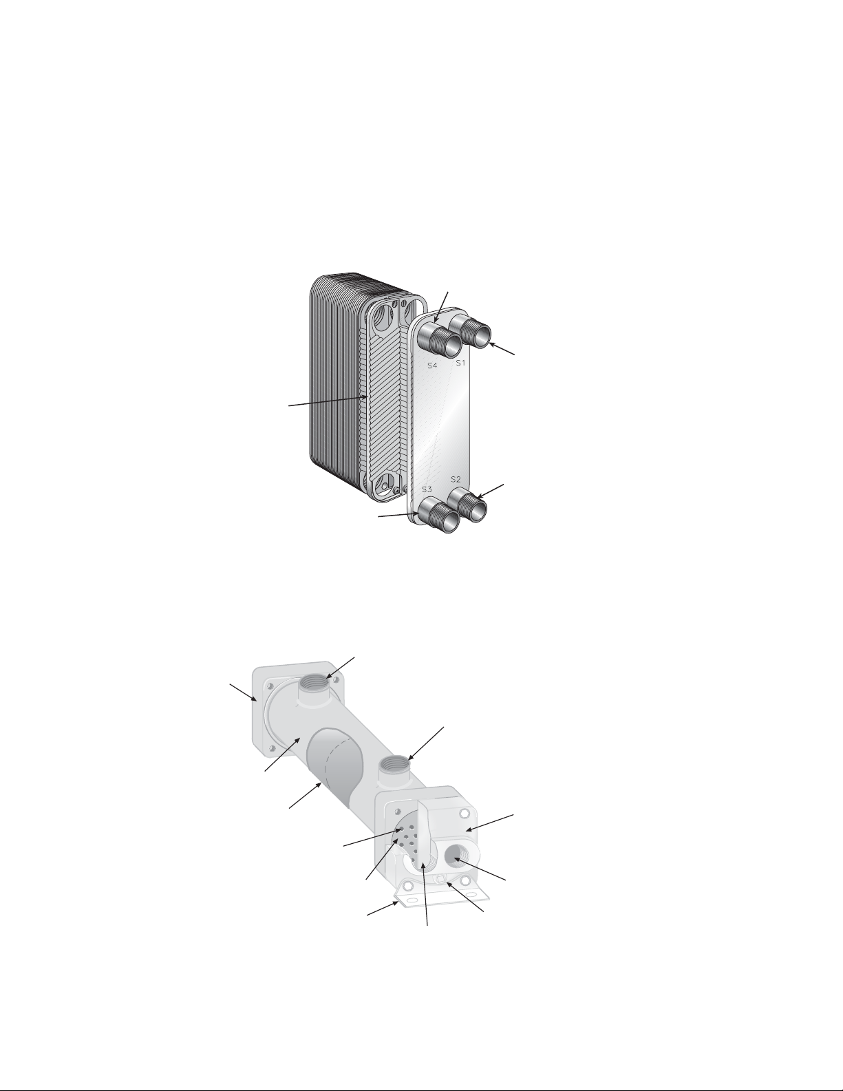
Plate design The plate design hydraulic fluid-to-water heat exchanger has no moving parts. It
consists of a series of corrugated stainless steel plates brazed together. The
direction of the herring bone design of the plates alternates to provide maximum
turbulence and therefore maximum cooling efficiency. The plates are brazed
together to provide strength and a compact package.
Fluid In
Plates
Water Out
Water In
Fluid Out
Cutaway View of a Plate Design Hydraulic Fluid-to-Water Heat Exchanger
Shell and tube design A shell and tube design hydraulic fluid-to-water heat exchanger has no moving
parts. It is composed of an outer shell, tubes, tube sheets, baffles (or fins), hubs
and bonnets:
Cool Fluid Out
Hub
Hot Fluid In
Shell
Baffles or Fins
Cooling Tubes
Tube Sheet
Mounting Bracket
Cooling Water In
End Bonnet
Cooling Water Out
Optional Zinc Anode
Cutaway View of a Shell and Tube Design Hydraulic Fluid-to-Water Heat Exchanger
Heat Exchanger Care
6
Heat Exchanger Care and Water Quality Guide
Page 7
• Shell–the shell is a seamless, nonferrous tube, usually made of brass. Both
ends are welded into the hubs. The shell encloses the baffles or fins very
closely to prevent any bypassing and ineffective flow areas.
• Tubes–straight, seamless, nonferrous tubes are usually made from copper, a
copper-nickel alloy or stainless steel.
• Tube sheets–brass tube sheets hold the cooling tubes in place. Tube sheets
are bonded to the inside of the hubs.
• Baffles or fins–brass baffles or fins provide a contact area for dissipating
heat. The hot hydraulic fluid flows around the baffles (fins), while the
cooling water flows through the tubes.
• Hubs–forged brass hubs are used to connect the shell with the end bonnets.
Vents and drains are located on the underside of the hubs.
• Bonnets–cast iron bonnets provide an unrestricted connection for cooling
water flow. Renewable zinc anodes may be attached in the bonnet to prevent
electrolytic damage.
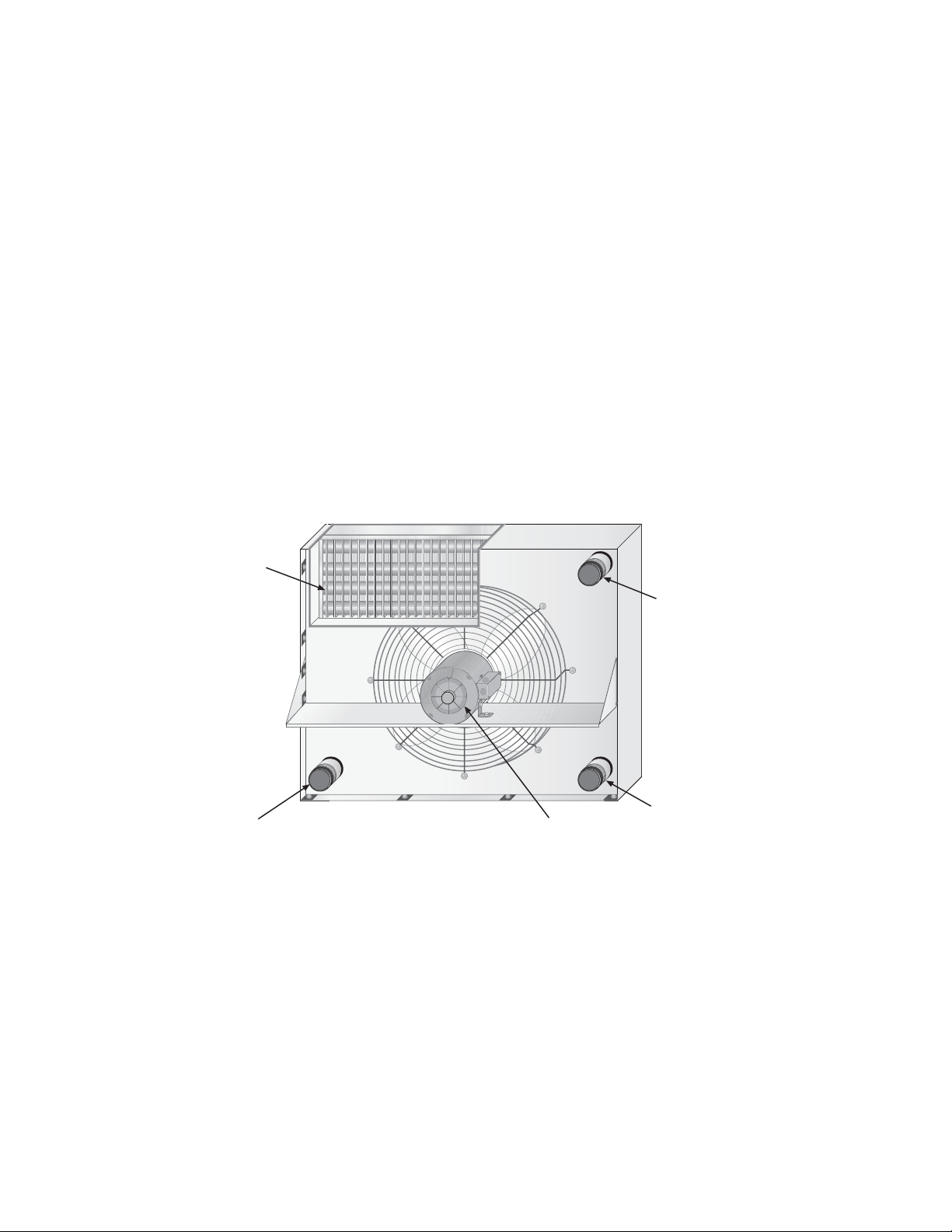
Hydraulic fluid-to-air A hydraulic fluid-to-air heat exchanger is composed of a motor and fan, tubes,
fins and a cabinet.
Tubes and Fins
Fluid In/Out Connection*
* Hot Fluid In/Cool Fluid Out connections vary between models
Cutaway View of a Hydraulic Fluid-to-Air Heat Exchanger
Motor and Fan
Fluid In/Out Connection*
Fluid In/Out
Connection*
Heat Exchanger Care and Water Quality Guide Heat Exchanger Care
7
Page 8

What ambient conditions are required?
Operating
temperatures
Water-cooled heat exchangers used in HPUs, operate at a minimum ambient
temperature of 4°C (40°F) and a maximum ambient temperature of 40°C
(104°F).
Air-cooled heat exchangers operate effectively up to an ambient temperatures of
37°C (98°F).
A nameplate specifying operating pressures and temperatures is attached to each
heat exchanger by the manufacturer. The MTS Hydraulic Power Supply Product
Manual provided with your test system contains specific information on the fluid
temperatures and cooling water requirements for your HPU.
The Air-Cooler to SilentFlo® HPU Integration Product Information manual
provides system integration requirements for
MTS Air-Coolers used with
MTS Series 505 SilentFlo™ Hydraulic Power Units.
Environment
Heat exchangers should not be located in a corrosive atmosphere, as rapid
deterioration of the brass casing, cooling element, fan and motor (hydraulic fluidto-air units only) may take place, resulting in a shortened operating life and
unnecessary replacement costs.
Water quality Water chemistry for hydraulic fluid-to-water heat exchangers, is critical for a
successful heat exchange system. Generally speaking, municipal drinking water
that is pollution free, bacteriologically safe, and has a neutral pH is perfectly
acceptable for hydraulic fluid-to-water heat exchangers.
Cooling tower water and natural water sources, such as wells, rivers, or ponds,
must be free of pollutants and treated to reduce contaminants to the same levels
as municipal drinking water.
Softened or distilled water may not be suitable as a cooling liquid because
although most of the minerals have been removed there is a higher than desirable
level of carbon dioxide and oxygen present in the water. High levels of carbon
dioxide and oxygen will act to decrease the protective layer of minerals that form
on the surface of the tube, and increase the formation of copper oxide.
If the source of cooling water is a cooling tower, the presence of contaminants
that are corrosive to metals will vary over time. Contaminants must be controlled
to the levels listed in the following table. Ideally, the pH level should be
maintained in the 6.5–8.0 range for most applications. Chlorine should be used to
limit the growth of microbiological organisms that are generated by protein
decay. You must be careful not to use excessive amounts of chlorine. The
chloride concentration in the cooling water must be kept to less than 5 ppm.
The following table lists the acceptable levels of common compounds allowed in
the cooling water supply:
Heat Exchanger Care
8
Heat Exchanger Care and Water Quality Guide
Page 9

Water Chemistry
Compounds found in water Allowable quantity (parts per million)
Ammonia
Bacteria
Calcium
Chlorides
Dissolved solids
none
must be bacteriologically safe
<800 ppm
<5 ppm
>50 but <500 ppm; limit to 150 ppm if
abrasive solids present
Iron
Nitrates
Nitrogen compounds
Oxidizing salts or acids
pH level
Silica as SiO
Sulfides
Sulfur dioxide
2
3 ppm
<10 ppm
none
none
6–8.5 recommended
<150 ppm to limit silica scale
<1 ppm
<50 ppm
Cooling towers located in an industrialized area should be a closed-loop design
to provide protection against airborne contaminants.
Different types of contaminants in the cooling water supply may react in
combination to create corrosion rates a hundred times higher than would be seen
by either contaminant acting alone. Cooling towers, unless regularly treated and
controlled, are the systems that have had the most problems with corroded heat
exchangers.
Local industrial water treatment specialists can provide information on your
water conditions and solutions to contaminant problems.
Heat Exchanger Care and Water Quality Guide Heat Exchanger Care
9
Page 10

What is the life expectancy of my heat exchanger?
All heat exchangers have a finite life and must be considered an expendable
component, subject to failure at some point in time. Properly used and
maintained, your heat exchanger could last up to 20 years.
What causes heat exchanger failure?
Heat exchangers usually provide a long service life with little maintenance other
than a routine inspection and cleaning. Fouling and corrosion are the main causes
of degraded performance or failure. A very expensive failure occurs when a leak
develops, allowing the cooling water to mix with the hydraulic fluid,
contaminating both the hydraulic system and the cooling water system.
Other heat exchanger failures can be caused by silting, scaling or other forms of
obstructing the cooling water passageways. These types of failures are not as
disastrous as corrosion failures, but can occur over time.
Fouling Fouling is the accretion of deposits that decrease the thermal transfer of a surface
and increase the system's flow resistance. The result is that due to reduced heat
transfer coefficients, the cooling water volumetric flow rate has to increase to
keep the system at the same temperature.
Corrosion Corrosion is the degradation of a metal due to chemical reactions with the
environment.
Shell and tube hydraulic fluid-to-water heat exchangers are usually constructed
with copper or copper alloy tubes. Copper and its alloys are normally resistive to
corrosion, but the corrosion rate will vary depending on the concentration of one
or more corrosive elements present in the hot hydraulic fluid or cooling water. A
normal corrosion rate is 5–25 µm per year. This implies an operating life of 20
years for your heat exchanger. Higher than expected corrosion rates will
drastically reduce this operating life.
Over a period of time, this slow dissolving of the metal will result in component
failure:
• Corrosion products may settle in the heat exchanger tubing, causing the
fluid flow to be blocked.
• Corrosion can eventually cause leaks between the water and hydraulic fluid
supplies.
– Water contamination in the hydraulic fluid can seriously shorten the
life of the hydraulic components of your HPU and test system.
– Hydraulic fluid in the water can result in a costly cleanup supervised by
your local environmental protection agency.
Which type of contamination occurs is dependent on the extent of the corrosion
and the pressure in the hydraulic fluid and water supplies. Since fluid tends to
flow from a high pressure area to one of low pressure, the lower pressure fluid
will become contaminated. Eventually, however, both the water and the supplies
may be contaminated as more leakage occurs.
Heat Exchanger Care
10
Heat Exchanger Care and Water Quality Guide
Page 11

Contaminated water
supply
The most likely cause of corrosion failure in heat exchangers is their use with
cooling towers. These towers use fan propelled ambient air to evaporate a portion
of the cooling water and thus cool the remaining water. This action transfers
whatever air pollution exists into the cooling water. Also, since the towers are
open to the environment, they are prone to collecting animal and vegetable
matter which is damaging to heat exchangers.
How can I prevent heat exchanger failure?
There are four types of heat exchanger failures that can occur: mechanical,
chemically induced corrosion, a combination of mechanical and chemically
induced corrosion, and fouling due to the accumulation of scale, solids, and
algae.
Mechanical failure Mechanical failures may take one of the following forms: metal erosion, water
hammer, vibration fatigue, thermal fatigue, or freeze-up.
• Metal Erosion: Excessive fluid velocity through the heat exchanger can
cause damaging erosion as the metal elements wear away. Any existing
corrosion is accelerated as erosion removes protective films from the metal,
exposing fresh metal to further attack.
Most metal erosion problems occur in the chambers and at the entrances to
the heat exchange. The entrance areas experience severe metal loss when
high-velocity fluid from a nozzle is divided into much smaller streams upon
entering the heat exchanger. This stream dividing results in extreme
turbulence with very high localized velocities.
The maximum recommended velocity in the chambers and at the entrance
nozzle is dependent on the chamber material, fluid handled, and
temperature. Materials such as stainless steel and copper-nickel can
withstand velocities of 10-11 ft/s (3.0-3.4 m/s). Copper is normally limited
to 7.5 feet per second (2.3 m/s). The water flow velocity in copper should be
kept less than 7.5 ft/s when it contai ns suspended solids or is softened.
• Water Hammer: Damaging pressure surges or shock waves can result from
an interruption in the flow of cooling water. To reduce your risk of water
hammer, the cooling water flow should always be started before heat is
applied to the exchanger.
Fluid flow control valves that open or close suddenly also produce water
hammer. Modulating control valves are preferable to on-off types.
• Vibration fatigue: Excessive vibration from equipment or transients in the
fluid flow (pulsating) can cause failures in the form of a fatigue stress crack
or erosion at the welded joints. Heat exchangers should be isolated from
excessive vibration.
• Thermal Fatigue: Fatigue resulting from accumulated stresses associated
with repeated thermal cycling can also cause failures. In thermal fatigue,
the temperature differences cause flexing, which produces a stress that acts
additively until the tensile strength of the material is exceeded and it cracks.
The crack usually runs radially and many times results in a total break.
A thermostatic or spring loaded by-pass relief valve installed ahead of the
heat exchanger will hasten warm-up and relieve the system of excessive
pressures, as well as control the hydraulic fluid temperature in certain
installations.
Heat Exchanger Care and Water Quality Guide Heat Exchanger Care
11
Page 12

• Freeze-Up: These failures can occur in a water cooled heat exchanger in
which the temperature drops below the freezing point of the cooling water.
Freeze-up results from failure to provide thermal protection, a malfunction
of the thermal protection control system, or protective heater device,
improper drainage of the unit for winter shutdown or an inadequate
concentration of antifreeze solutions.
Chemically induced
corrosion
Chemically induced corrosion failures result from the complex chemical
interaction between the materials of the heat exchanger and the fluids circulated
through it. There are several types of chemically induced corrosion failures:
general corrosion, pitting, stress corrosion, dezincification, galvanic corrosion,
and crevice corrosion.
• General corrosion: This type of corrosion is characterized by a slow,
uniform attack over the chamber material, with little or no evidence that
corrosion is taking place.
In copper, low cooling water pH (less than 7) combined with carbon dioxide
or oxygen produces corrosion. A blue or bluish-green color on the material
are indicative of carbon dioxide attack inside the chamber. Various
chemicals, such as acids, also produce this type of metal loss.
You can reduce general corrosion and maximize the li fe of yo ur heat
exchanger by selecting a material with adequate corrosion resistance for the
operating environment and by using the proper treatment chemicals to clean
and protect the components of your heat exchanger.
• Pitting: Localized pitting is frequently encountered in metals. It is caused by
the electrochemical potential set up by differences in the concentration of
oxygen within and outside the pit, and is frequently referred to as a
concentration cell. The oxygen-starved pit acts as an anode and the
unattacked metal surface as a cathode. A small number of pits may be
present; however, any one can cause a heat exchanger failure.
Pitting corrosion is most likely to occur during shut-down periods when
there is no fluid flow and the environment is most suitable for the buildup of
concentration cells. Imperfections such as scratches, dirt or scale deposits,
surface defects, breaks in protective scale layers, breaks in metal surface
films and grain boundary conditions increase the susceptibility of the metal
to pitting corrosion.
Heat Exchanger Care
12
• Stress corrosion: This form of corrosion attacks the grain boundaries
(changes in the crystalline structure of the metal) in stressed areas. Heat
exchangers usually have residual stresses that are the result of drawing or
forming the materials during manufacturing.
Failures from stress corrosion take the form of fine cracks, which follow the
lines of stress and material grain boundaries. All naturally occurring waters
contain the chloride ion, which is potentially present in any compound
formulated with chlorine. The frequency of chloride stress corrosion rises
with an increase in temperature and chloride ion concentration. Keeping
chamber wall temperatures below 125°F (52°C) prevents stress corrosion
cracking problems with chloride ion concentrations up to 50 ppm.
The substance that causes stress corrosion cracking on copper or copper
alloy is ammonia. Very small concentration (1 ppm or less) can create a
problem. Copper-nickel alloys have good resistance to stress corrosion
cracking and should be used in applications where low concentrations of
ammonia are expected.
Heat Exchanger Care and Water Quality Guide
Page 13

• Dezincification: This problem occurs in copper-zinc alloys containing less
than 85 percent copper when they are in contact with water having a high
oxygen and carbon dioxide content, or in a stagnant solution. The effect
tends to accelerate as temperature increases or pH decreased below 7.
Dezincification creates a porous surface in which the zinc is chemically
removed from the alloy. The remaining copper has a sponge-like
appearance. Dezincification is prevented by using a brass with lower zinc
content or a brass containing tin or arsenic to inhibit the chemical action, or
by controlling the environment causing the problem.
• Galvanic (electrical current) corrosion: This type of corrosion occurs when
dissimilar metals are joined in the presence of an electrolyte, such as acidic
water. Galvanic corrosion usually produces a higher rate of reaction on the
less noble (chemically inert) metal.
• Crevice corrosion: This type of corrosion originates in and around hidden
and secluded areas, such as between baffles and tubes, or under loose scale
or dirt. A localized cell develops and the resulting corrosion appears as a
metal loss with local pits, often giving the impression that erosion is taking
place. This condition is in contrast to a vibration failure in which the metal
is sharply cut and there are no pits. Relatively stagnant conditions must exist
for crevice corrosion to occur.
Crevice corrosion can often be controlled by making sure that fluid flow
velocities are adequate to prevent stagnation or the accumulation of solids.
Mechanical failure with chemically induced corrosion
Heat exchanger failure is often not from a single cause, but a combination of
more than one condition. Quite often, a mechanical problem combined with a
corrosion problem produces a quicker failure than either of them alone. There are
two common types of combination mechanical and corrosion failures: erosioncorrosion and corrosion-fatigue.
• Erosion-corrosion: any corrosion is greatly accelerated if the protective
films are worn away by excessive velocity, suspended solids, or mechanical
vibration. Erosion-corrosion is usually found in the entrance area of
chambers, below the inlet nozzles, at the point of contact of two surfaces
such as where baffles and tubes meet.
• Corrosion-fatigue: in this dual failure mode, stresses associated with
fatigue are the result of externally applied mechanical loads, such as
vibrations from machinery , expansion or contraction because of temperature
cycles, or light water hammer. In most envi ronments where only corrosion
occurs, corrosion products and films block or retard further attack.
However, in corrosion-fatigue, cyclic stresses rupture the protected areas
and make them permeable; this action subjects open areas to accelerated
corrosion.
Heat Exchanger Care and Water Quality Guide Heat Exchanger Care
13
Page 14

Fouling due to
accumulation of scale,
solids, and algae
Various compounds and marine growth s present in cooling water will deposit a
film or coating on heat transfer surfaces. The film acts as an insulator, restricting
heat flow and protecting corrosive compounds. As a result of this insulating
effect, temperatures go up and corrosion increases.
• Scale is the result of dissolved minerals precipitating out of heat transfer
fluids. The solubility of these minerals is affected by changes in temperature
within the heat exchanger and chemical reactions between compounds
found in the cooling water. MTS has designed your HPU to have an
optimum fluid velocity based on the heat exchanger material and the heat
transfer needs of your system. This fluid velocity is normally sufficient to
keep the rate of precipitation low. If your fluid velocity decreases due to
fouling or clogging of the tubes, the rate of precipitation will increase.
Regular cleaning of the tubes and inlet filters will keep the fluid velocity
high enough to inhibit scaling.
• Suspended solids are usually found in the form of sand, iron, silt, or other
visible particles in one or both of the heat transfer fluids. If fluid velocities
are not high enough to keep them in suspension, particles settle out and
build up on the chamber walls. Suspended solids are very abrasive to
chambers and other heat exchanger parts. The proper use of filters and
screens for the cooling water and hydraulic fluid will reduce the presence of
abrasive particles in the fluid and protect your heat exchanger from erosion
damage.
• Algae and other marine growths are a serious problem if they get in the heat
exchanger. In many cases, the environment in the heat exchanger is
conducive to rapid proliferation of algae and other marine growths, which
restrict cooling water flow and impede heat transfer. A chemical algicide,
such as chlorine, is effective in controlling algae and other marine growths;
high fluid velocities also discourage them from proliferating.
How do I know when I have a heat exchanger failure?
The first indication of a hydraulic fluid-to-water heat exchanger failure is a milky
or cloudy coloration of the hydraulic fluid, indicating a water content greater than
0.2–0.3% by weight. Hydraulic fluid in the water discharge is also a sign of heat
exchanger failure. A corrosion failure starts as a small pin hole, which produces a
very low flow of water into the hydraulic fluid. Checking the hydraulic fluid
color on a daily basis will reduce the amount of water contamination and the
severity of the damage.
Heat Exchanger Care
14
Heat Exchanger Care and Water Quality Guide
Page 15

How can I improve the life of my heat exchanger?
Routine inspections and maintenance enable you to slow the degradation effects
in heat exchangers. The effects will always be present, however, and will sooner
or later result in the necessity of replacing the degraded components.
Choose the right
material for your water
conditions
Plate design heat
exchangers
Tube and shell design
heat exchangers
Although you cannot prevent corrosion from ever occurring in your heat
exchanger, the corrosion rate can be reduced by selecting the appropriate
materials for your heat exchanger. MTS can assist its customers in selecting the
proper material for heat exchangers (copper, copper-nickel alloy or stainless
steel) based on an analysis of the water supply.
The plate design heat exchanges use stainless steel plate because if it general
resistance to most of the cause for corrosion making it suitable for use with most
sources of fresh water: city water, pond water or cooling towers. The city water
should have a chloride content of <5 ppm. Pond water should be filtered or
screened and cooling towers must be properly maintained to prevent fouling. The
cooling water can have a ph of 7 to 8.5
MTS does not recommend using stainless steel plates if your cooling water is
saltwater or sea water.
The standard material used in heat exchanger tubes is 99.9% pure soft copper.
Copper-nickel (CuNi), an alloy of copper that has 10% nickel, offers a high
resistance to corrosion caused by many common pollutants. A 90-10 copper alloy
tube has a corrosion rate that is typically one-half to one-third that of pure copper,
and adds 20–25% to the cost of the heat exchanger. This alloy is a good solution
to the problem of mildly corrosive water, such as ground water supplies. But it is
not a solution to severe corrosion problems that may occur when cooling towers
are used.
Another measure that can be taken to enhance heat exchanger life is to add zinc
anodes to the heat exchanger bonnet. Most copper-nickel heat exchangers can be
furnished with zinc anodes. These anodes screw into a threaded opening added to
the bonnet, and protect the tube sheet and bonnet metal against dezincification
corrosion. The zinc anodes will corrode before the copper alloy tubes in most
cases. Zinc protection from the zinc anodes will decrease with time because of
metal loss, so the zinc anodes should be inspected regularly and replaced as
required.
MTS recommends that if your cooling water supply is saltwater or sea water, heat
exchangers with 90-10 copper-nickel tubes and tube sheets, bronze bonnets and
zinc anodes should be used to reduce the corrosion rate.
Keep your water
supply clean
Heat Exchanger Care and Water Quality Guide Heat Exchanger Care
Contaminants in the cooling water supply can partially or completely block the
heat exchanger chambers. Blocked chambers will decrease the efficiency of the
heat exchanger and may result in damaging erosion or corrosion. Dirt or small
objects, such as organic material may coat the chambers and lead to corrosion.
Y ou can prevent sediment buildup in the chambers by installing a filter or strainer
in the cooling water inlet to prevent large particles from entering the chambers.
MTS recommends that water strainers be installed ahead of the heat exchanger if
the source of cooling water contains large amounts of particles or sediment.
Note Because most corrosives are dissolved solids, strainers usually provide
only minimal corrosion protection. A strainer will be useful in preventing
corrosion damage only in those instances where a suspended solid is
corrosive.
15
Page 16

Monitor the cooling
water flow rate
The easiest way to prevent fouling is by assuring that there is a sufficient flow of
cooling water in all of the chambers. This will maintain a “self-cleaning” effect
in the chambers, which also helps them retain their heat transfer characteristics. If
you notice a decrease in the efficiency of your heat exchanger, inspect the filter
or strainer and the chambers for signs of fouling.
When there is a possibility of cooling water surge pressures above the design
pressure of the heat exchanger, a pressure relief or regulating valve should be
installed to protect the exchanger from bursting pressures.
Protect your heat
exchanger during
shipping or storage
To prevent corrosion during shipment and short-term storage, MTS flushes the
chambers with Dow Chemical's Dowfrost HD antifreeze (propylene glycol) after
testing the HPU and preparing it for shipment. Dowfrost HD is a heat transfer
fluid designed to be used in closed loop HVAC systems. It has excellent anticorrosion properties and is low in toxicity . The HD signifie s that this Dowf rost is
designed to work with the different metals in heat exchangers. MTS warns
against using flushing solutions of ethylene glycol, which can be very corrosive
under certain conditions.
If your heat exchanger is to be shut down or stored for a period of time (weeks or
months) MTS recommends that you drain the heat exchanger and flush it with a
corrosion-preventive fluid to prevent corrosion. Keep the heat exchanger ports
sealed to prevent the entry of dirt or other foreign matter. The heat exchanger
should always be drained when the ambient temperature is less than 32 °F (0°C)
to prevent freezing of the cooling fluid and damage to the components.
What regular heat exchanger maintenance is required?
T o maintain the life of your heat exchanger, you must service it periodically. The
frequency in which you clean your heat exchanger internally and externally,
depends on the nature of its operating environment and how rapidly it will foul.
Before you use the
heat exchanger for the
first time
Upon receipt of your HPU, MTS recommends that you inspect the heat
exchanger thoroughly, making sure that no dirt or foreign matter entered the unit
during shipment. Check the bolts on the heat exchanger and tighten them if
necessary. The heat exchanger should be mounted solidly in place.
For all types of heat
exchangers
Heat Exchanger Care
16
Regular inspection of your heat exchanger will help you identify any decrease in
the efficiency of your heat exchanger. In addition to regular inspections, MTS
recommends that you follow these guidelines:
• Keep a log of data to monitor changes in temperature and pressure.
Collecting and comparing performance data at regular intervals will help
you identify any loss of efficiency and determine the proper interval
required between cleanings.
A loss of efficiency can usually be traced to an accumulation of water scale.
MTS has designed your HPU to provide a fluid velocity of 0.6–1.8 m/s (2-6
ft/s) through the heat exchanger. This flow rate is normally sufficient to keep
a heat exchanger relatively clean.
• Inspect the hydraulic fluid and cooling water often for signs of
contamination. Hydraulic fluid that has water in it will appear cloudy.
Heat Exchanger Care and Water Quality Guide
Page 17

• Be careful using sealant tape on pipe threads, which lessens the degree of
resistance between mating parts, and results in a greater chance for cracking
the heat exchanger castings. Do not over-tighten pipe connections when remounting the heat exchanger after you have disassembled it for
maintenance.
• When you are ordering replacement parts, mention the model and serial
number of the heat exchanger, the model of the HPU and the original MTS
job number.
WARNING
For hydraulic fluid-to-
water heat exchangers
only
Stainless steel plate
heat exchangers
Commercial solvents may cause irritation to eyes and skin.
Always wear protective clothing, eye protection, and if required a respirator. Follow the
manufacturer's safety instructions when using chemicals.
Depending on fouling conditions, MTS recommends inspecting your heat
exchanger every 500–2000 operating hours. If you notice a decrease in the
efficiency of your heat exchanger, it should be cleaned.
1. Clean all filters and screens.
2. Begin with an external inspection of the heat exchanger. Visually inspect
for:
• Corrosion
• Signs of a previous repair
• Leakage
3. A marked decrease in pressure and/or reduction in performance usually
indicates cleaning is necessary. The following are suggested methods of
cleaning either side of the heat exchanger.
• Back flush the heat exchanger with a high pressure stream of hot water
to remove loose deposits
• Circulate hot wash oil or light distillate to remove sludge or similar soft
deposits.
• To remove more stubborn deposits, try a commercial cleaning
compound such as “Oakite” or “Dowell”. Follow the manufacturers
instructions for using the cleaning compound.
Important It is recommended that you contact a representative of the
manufacturer of the cleaning compound to determine the
correct cleaning compound for your type of scaling problem
and its compatibility with the metals and alloys used in the
heat exchanger.
4. If the heat exchanger is excessively fouled and cannot be cleaned using the
commercial cleaning methods, then replacement of the heat exchanger is
recommended.
Heat Exchanger Care and Water Quality Guide Heat Exchanger Care
17
Page 18

Tube and shell heat
exchangers
1. Clean all filters and screens.
2. Begin with an external inspection of the heat exchanger. Visually inspect
for:
• Dents or bulges in the shell
• Extruded or damaged gaskets
• Corrosion
• Damaged flanges on the bonnets and hub or tube sheets
• Stress marks in the shell
• Signs of a previous repair
• Leakage
3. After you have completed the external inspection, continue with an internal
inspection of the heat exchanger:
A. Completely drain and inspect the tubing and internal parts to determine
the extent of cleaning necessary. If severe fouling or corrosion of the
tubes and/or bonnets of the tube and shell heat exchanger is found, then
disassembly of the heat exchanger may be necessary.
B. If disassembly of the heat exchanger is required, discard the old gaskets
and replace them with new ones. Visually inspect for the following:
• Damage to the tube ends due to corrosion or erosion
• Wearing of the zinc anodes (co pper-nickel tubing units)
• Damage to the nozzle threads on the tube and shell side
• Erosion of the tubes under the shell side nozzle
Signs of any of the above conditions may indicate high flow rate with
particle entrainment in the fluid, or the presence of a corrosive
environment. Depending on the degree of degradation of the unit, it
may need replacement.
C. Inspect all zinc anodes and replace them if a marked corrosion is
visible. If they are coated with scale, remove the scale.
D. Unscrew and remove the bonnets, carefully inspect the tubes for
corrosion, erosion and any foreign materials and clean as required.
Note Protect the baffle plates and tubes from damage. Bent baffle plates will
cause in the hydraulic fluid to bypass the tube surface, resulting in a
decrease in heat transfer rate.
Be careful when you remove or handle the tube bundle of a removable
tube bundle exchanger.
Heat Exchanger Care
18
Heat Exchanger Care and Water Quality Guide
Page 19

Mechanical cleaning Complete the following steps if your internal inspection of the shell and tube heat
exchanger indicates that you need to remove any sediment or light scale from the
tubes:
1. Remove residues from the inside of the tubes with a rotary brush. Use a soft
nylon brush to prevent scratches in the metal surfaces since any scratches
will accelerate corrosion.
2. Flush the tubes with clean water to remove dirt and scale loosened during
the brushing.
3. Pressurize the shell side to verify the integrity of the tubes and all joints
before reassembling the heat exchanger.
4. Clean the bonnets as required, and reattach them to the heat exchanger. New
gaskets are required whenever you re-assemble the heat exchanger. Use of
oiled gaskets is acceptable.
5. Pressure test the tube side.
Chemical cleaning Internal chemical cleaning of the tubes is required to remove calcium deposits
that build up in and around the tubes over time. Clean and flush the internal tubes
regularly.
1. Clean the internal water passage by flushing with a 15% solution of
inhibited muriatic acid (hydrochloric acid) in water. The length of time
required for flushing is dependent on the amount of scale built up in the
tubing. For 1 mm scale, flush the tubes for about 30 minutes. The system
must be open to vent gases as they become free.
For hydraulic fluid-to-
air heat exchangers
only
2. Drain completely, then flush the tubes thoroughly with clean water.
3. Repeat the flushing with a neutralizing agent, such as a 5% sodium
carbonate solution, and drain completely. Flush with clean water.
4. Repeat the process in the opposite flow direction.
5. Remove any fluid residue with a commercial solvent.
Depending on fouling conditions, MTS recommends inspecting your heat
exchanger every 500–2000 operating hours. If you notice a decrease in the
efficiency of your heat exchanger, it should be cleaned.
1. Clean all filters and screens.
2. Inspect the unit regularly for loose bolts and connections, rust, corrosion and
dirty or clogged heat transfer surfaces.
3. Remove dirt and dust from the heat transfer surface by brushing the fins and
tubes and blowing loose dirt off with an air hose or by turning on the fan. If
the surface is greasy , remove the motor and spray or brush the fins and tubes
with a mild alkaline solution or a nonflammable degreasing fluid. Follow
the degreasing with a hot wat er rins e and dr y th oroughl y. A steam hose may
also be used effectively.
4. Remove any dirt and grease from the casing, fan and motor. Sand and
repaint rusty or corroded surfaces.
Heat Exchanger Care and Water Quality Guide Heat Exchanger Care
19
Page 20

5. Keep the motor outside surface of direct drive heat exchangers free of dirt
and grease so the motor will cool properly. Make sure the cooling air over
the motor is not obstructed. Pre lubricated ball bearing motors require no
lubrication for extended periods of time. Follow the lubrication instructions
attached to the motor and provided by the motor manufacturer.
6. The combination fan hub and sheave assembly on external drive heat
exchangers is pre lubricated at the factory prior to shipment. Lubricate the
assembly after every 1000 hours of operation following the manufacturer's
instructions.
How do I remove corrosion?
MTS recommends you use Dowfrost HD, an industrially inhibited propylene
glycol fluid to remove corrosion from the tubes and protect them from future
corrosive attack.
1. Clean new or lightly corroded existing systems with a 1–2% solution of
trisodium phosphate in water prior to the installation of the Dowfrost HD.
2. Extensively corroded systems should be cleaned by an industrial cleaning
company and all necessary replacements and repairs should be made before
the heat exchanger is used again.
How do I remove water from the hydraulic fluid after a heat exchanger failure?
Once a heat exchanger failure occurs, remove the damaged unit from service and
assess the amount of water in the hydraulic fluid. If the contamination is severe
(the water content is greater than 2. 0% by weight), the sensible approach may be
to drain and discard the hydraulic fluid in the distribution system. If discarding
the contaminated fluid is not desirable of feasible, the hydraulic fluid can be left
standing and a large portion of the water will separate out. This water can then be
siphoned from the bottom of the reservoir. Water absorbing filter elements can be
used in the HPU to remove most of the water from the hydraulic fluid.
The hydraulic distribution system also requires attention after a heat exchanger
failure. Water will tend to settle in low points in the system. These points should
be drained and the fluid discarded. If contamination is not severe (water content
is less than 1.0% by weight), it may be advisable to simply flush the system with
the “dry” fluid from the HPU, and continue dry filtering the water.
How do I know when to replace my heat exchanger?
Watch for changes and trends in your regular analysis of the hydraulic fluid (for
example, the copper counts in the hydraulic fluid may rise with each analysis). A
slow trend is nothing to worry about, but a sudden change in the fluid analysis
may indicate that your heat exchanger will fail soon.
Heat Exchanger Care
20
Heat Exchanger Care and Water Quality Guide
Page 21

Acceptable Ranges for Copper
Copper Concentration Indication
20–50 (ppm)
>50 (ppm)
Normal amounts
Watch for additional trends in the
hydraulic fluid analysis
Sharp rise
There is a problem which requires
immediate action
Look for the presence of hydraulic fluid in the cooling water, or water in the
hydraulic fluid. MTS has water-in-fluid and fluid-in-water sensors available to
aid in the early detection of contamination of your cooling water or hydraulic
fluid. Contact MTS for more information.
Replace the heat exchanger at the first signs of a problem. If you wait for a
catastrophic failure, you will contaminate the entire cooling water supply, ground
water or hydraulic system and face expensive cleanup costs and the loss of
valuable time that could be devoted to testing. If the ground water becomes
contaminated, your company may face severe penalties and cleanup costs for
environmental damage. If you have several pumps on the same hydraulic supply
line, you risk damaging them and incurring the added expense of repairing
several heat exchangers and hydraulic power units.
Heat Exchanger Care and Water Quality Guide Heat Exchanger Care
21
Page 22

Troubleshooting
Symptoms Corrective Action
HPU won't cool (hydraulic
fluid-to-water models)
Heat exchanger is plugged
Heat exchanger leaks
externally
• Verify the proper water connections:
IN→IN
OUT→OUT
• Verify that the water temperature vs. flow rate is correct for your
model of HPU (refer to the MTS Hydraulic Power Supply Product
Manual that came with your system).
• Verify that the operation of the water saver valve is correct. Adjust it
if necessary (refer to the instructions in the MTS Hydraulic Power
Supply Product Manual that came with your system).
• Perform a mechanical cleaning
• Perform a chemical cleaning as needed
• Install a filter in the cooling water inlet line to prevent the buildup of
sediment
• Ensure that you are using clean cooling water
• Inspect the heat exchanger for signs of corrosion
• Repair the leak
• If the leak occurs at a fitting, it may be loose. Remove the fitting,
inspect it and repair or replace it as necessary. Re-install the fitting,
being careful not to over tighten it.
Heat exchanger leaks
internally
Troubleshooting
22
• Disassemble the heat exchanger
• Conduct a pressure test to determine the location of the leak
• Repair the leak if possible, or replace the heat exchanger
Heat Exchanger Care and Water Quality Guide
Page 23

Page 24

m
MTS Systems Corporation
14000 Technology Drive
Eden Prairie, Minnesota 55344-2290 USA
Toll Free Phone: 800-328-2255
(within the U.S. or Canada)
Phone: 952-937-4000
(outside the U.S. or Canada)
Fax: 952-937-4515
E-mail: info@mts.com
http://www.mts.com
ISO 9001:2000 Certified QMS
 Loading...