

Page 1
MTS TestSuite
TW Elite Test Design Guide
100-234-122 G be certain.
Page 2

©
2014 MTS Systems Corporation. All rights reserved.
Trademark Information
MTS is a registered trademark of MTS Systems Corporation within the United States. This trademark
may be protected in other countries.All other trademarks or service marks are property of their respective
owners.
Proprietary Software
Software use and license is governed by MTS’s End User License Agreement which defines all rights
retained by MTS and granted to the End User. All Software is proprietary, confidential, and owned by
MTS Systems Corporation and cannot be copied, reproduced, disassembled, decompiled, reverse
engineered, or distributed without express written consent of MTS.
Software Verification and Validation
MTS software is developed using established quality practices in accordance with the requirements
detailed in the ISO 9001 standards. Because MTS-authored software is delivered in binary format, it
is not user accessible. This software will not change over time. Many releases are written to be
backwards compatible, creating another form of verification.The status and validity of MTS’s operating
software is also checked during system verification and routine calibration of MTS hardware. These
controlled calibration processes compare the final test results after statistical analysis against the
predicted response of the calibration standards. With these established methods, MTS assures its
customers that MTS products meet MTS’s exacting quality standards when initially installed and will
continue to perform as intended over time.
Manual Part Number—Publication Date—Release
100-234-122 G—February 2014—MTS TestSuite TW 2.3.4 or later
100-234-122 F—September 2013—MTS TestSuite TW 2.3.1
100-234-122 E—August 2013—MTS TestSuite TW 2.3
100-234-122 D—January 2013—MTS TestSuite TW 2.2
100-234-122 C—December 2012—MTS TestSuite TW 2.1
Page 3

Table of Contents
Preface
Before You Begin.............................................................................................................................................7
Documentation Conventions............................................................................................................................7
Technical Support
How to Get Technical Support.......................................................................................................................11
Before You Contact MTS...............................................................................................................................11
If You Contact MTS by Phone.......................................................................................................................13
Problem Submittal Form in MTS Manuals....................................................................................................14
Introduction
About This Guide...........................................................................................................................................16
Start TWE and Open the Example Test..........................................................................................................17
TWE Main Window.......................................................................................................................................17
Main Window Toolbar.......................................................................................................................20
About the Multi-Head Run Section....................................................................................................21
Multi-Head Run Section Properties...................................................................................................22
Table of Contents
Examine the Example Test
About this Chapter.........................................................................................................................................26
Design Flow...................................................................................................................................................26
Dene Tab......................................................................................................................................................27
Outline View in the Procedure Subtab...............................................................................................27
Workow in the Procedure Subtab....................................................................................................28
Set Up Section........................................................................................................................29
Run Section............................................................................................................................30
Examining the Logic in the Run Section................................................................................32
Program Command in the Example Test................................................................................33
Branches in the Parallel Paths Activity..................................................................................34
Go To + DAQ + Detection Activity.......................................................................................35
Finish Section.........................................................................................................................39
Test-Run Display Subtab....................................................................................................................40
Variables Subtab.................................................................................................................................40
Variable Denition.................................................................................................................41
Variable Use in the Example Test...........................................................................................41
Variable Availability Attributes..............................................................................................42
Report Templates Subtab....................................................................................................................43
Functions Subtab................................................................................................................................44
3
Page 4

Table of Contents
Resources Subtab...............................................................................................................................45
Test Denition Subtab........................................................................................................................47
Monitor Tab....................................................................................................................................................49
Review Tab Layout........................................................................................................................................51
Review Tab Toolbar...........................................................................................................................52
Test Run Results Table.......................................................................................................................53
Statistics Table....................................................................................................................................54
Panel of Charts and Tables.................................................................................................................54
Four-Panel View.................................................................................................................................56
Runtime Values Tab........................................................................................................................................57
Design Guidelines
About this Chapter.........................................................................................................................................60
Designing Tests..............................................................................................................................................60
Test Design Checklist.........................................................................................................................60
Tests and Templates............................................................................................................................61
Modifying Tests..................................................................................................................................63
Working With Variables.....................................................................................................................69
Conguring Data Acquisition............................................................................................................74
Choosing a Template to Run or Modify.................................................................................61
File Icons................................................................................................................................61
Working with Templates and Tests.........................................................................................62
Adding and Conguring Test Activities................................................................................63
Considerations for Test Sections ...........................................................................................65
Conguring What is Displayed After Test Runs....................................................................67
Interacting with the Operator During Tests............................................................................67
Run-Time Markers.................................................................................................................67
Batch Mode Tests...................................................................................................................67
Pre-Allocating Multiple Test Runs.........................................................................................68
Variable Concepts ..................................................................................................................69
Benets of Using Variables....................................................................................................69
Using Variables in Activities..................................................................................................70
Toggling Between Static Values and Variables......................................................................70
Variable Example...................................................................................................................70
Manipulating Variables in the Workow ..............................................................................71
Assigning Variable Availability..............................................................................................72
Adding Calculations to Variables ..........................................................................................72
Managing Variables................................................................................................................73
Used By Table Column..........................................................................................................74
Data Acquisition Properties Page...........................................................................................74
Mapping Variables to Acquired Data.....................................................................................74
Acquiring Data in a Continuous Stream.................................................................................75
4
Page 5

Acquiring Data in Blocks Without Mode Switching.............................................................75
Acquiring Data in Blocks With Mode Switching...................................................................75
Setting Buffer Size.................................................................................................................75
Data Acquisition for Test-Run Displays................................................................................76
Polarity Considerations for MTS Criterion Series 40 Systems .........................................................76
Debugging..........................................................................................................................................78
Automatic Saves and Experimentation..................................................................................79
Rapid Design Iterations..........................................................................................................79
Activity State in Outline View...............................................................................................79
Test Procedure Test-Run Display...........................................................................................79
Runtime Values Tab................................................................................................................79
Modify the Example Test
About this Chapter.........................................................................................................................................82
Modifying Tests..............................................................................................................................................82
Design Scenario..............................................................................................................................................83
Modifying the Set Up Section............................................................................................................83
Formula Assistant File...........................................................................................................84
Changing the Specimen Geometry.........................................................................................84
Adding an Input Variables Activity .......................................................................................86
Moving and Enabling Run External Application Activity.....................................................88
Modifying the Run Section................................................................................................................88
Enable and Congure the Custom Message Window Activity..............................................89
Editing the Go To + DAQ + Detection Activity ...................................................................90
Modifying the Finish Section.............................................................................................................92
Changing the Maximum Test Runs Variable..........................................................................92
Enabling and Conguring the Run Report Activity...............................................................93
Table of Contents
Working with MTS FlexTest Resources
Resource Basics..............................................................................................................................................96
Connecting to a Controller.............................................................................................................................96
Creating a Desktop Shortcut That Includes a Controller...............................................................................98
Station Congurations....................................................................................................................................98
Controller Resources......................................................................................................................................99
Resource Mapping..........................................................................................................................................99
Ofine Test Design......................................................................................................................................102
Resources That Allow Dimension Changes.................................................................................................103
Considerations for Servohydraulic Systems
Understand Software Concepts....................................................................................................................106
Using MTS TestSuite with Controller Software..........................................................................................106
5
Page 6

Table of Contents
Station Controls Panel......................................................................................................................107
Station Conguration Files..............................................................................................................108
TWE Startup.....................................................................................................................................109
Working with Limits........................................................................................................................109
Set Station Detector Limits..................................................................................................110
Access and Set Detector Settings.........................................................................................110
Reset Detectors.....................................................................................................................112
Using Manual Command to Install the Specimen............................................................................112
Manual Command Properties...............................................................................................112
Manually Position the Actuator............................................................................................114
Applying Offsets to the Input Signal (optional)...............................................................................115
Apply an Auto Offset to an Input Signal..............................................................................115
Apply a Manual Offset to an Input Signal...........................................................................115
TW Elite for TestWorks 4 Users
About this Chapter.......................................................................................................................................118
Basic Concepts.............................................................................................................................................118
Terminology Differences..............................................................................................................................119
Functional Differences.................................................................................................................................122
Converting TestWorks 4 Methods and Sample Files...................................................................................125
Conversion Issues for MTS FlexTest Controllers........................................................................................125
6
Page 7
Preface
Before You Begin
Safety first!
Before you use your MTS product or system, read and understand the safety information provided with
your system. Improper installation, operation, or maintenance can result in hazardous conditions that can
cause severe personal injury or death, or damage to your equipment and specimen. Again, read and
understand the safety information provided with your system before you continue. It is very important that
you remain aware of hazards that apply to your system.
Other MTS manuals
In addition to this manual, you may receive additional manuals in paper or electronic form.
You may also receive an MTS System Documentation CD. It contains an electronic copy of the manuals
that pertain to your test system.
Controller and application software manuals are typically included on the software CD distribution disc(s).
Documentation Conventions
The following paragraphs describe some of the conventions that are used in your MTS manuals.
Hazard conventions
Hazard notices may be embedded in this manual. These notices contain safety information that is specific
to the activity to be performed. Hazard notices immediately precede the step or procedure that may lead
to an associated hazard. Read all hazard notices carefully and follow all directions and recommendations.
Three different levels of hazard notices may appear in your manuals. Following are examples of all three
levels. (for general safety information, see the safety information provided with your system.)
Danger:
Danger notices indicate the presence of a hazard with a high level of risk which, if ignored,
will result in death, severe personal injury, or substantial property damage.
MTS TestSuite | 7
Page 8
Preface
Warning:
Warning notices indicate the presence of a hazard with a medium level of risk which, if ignored,
can result in death, severe personal injury, or substantial property damage.
Caution:
Caution notices indicate the presence of a hazard with a low level of risk which, if ignored,
could cause moderate or minor personal injury or equipment damage, or could endanger test
integrity.
Other special text conventions
Important:
Important notices provide information about your system that is essential to its proper
function. While not safety-related, if the important information is ignored, test results may
not be reliable, or your system may not operate properly.
Note:
Notes provide additional information about operating your system or highlight easily
overlooked information.
Recommended:
Recommended notes provide a suggested way to accomplish a task based on what MTS
has found to be most effective.
Tip:
Tips provide helpful information or a hint about how to most efficiently accomplish a task.
Access:
Access provides the route you should follow to a referenced item in the software.
Examples show specific scenarios relating to your product and appear with a shaded
background.
Special terms
The first occurrence of special terms is shown in italics.
Illustrations
Illustrations appear in this manual to clarify text. They are examples only and do not necessarily represent
your actual system configuration, test application, or software.
8 | MTS TestSuite
Page 9

Preface
Electronic manual conventions
This manual is available as an electronic document in the Portable Document File (PDF) format. It can be
viewed on any computer that has Adobe Acrobat Reader installed.
Hypertext links
The electronic document has many hypertext links displayed in a blue font. All blue words in the body text,
along with all contents entries and index page numbers, are hypertext links. When you click a hypertext
link, the application jumps to the corresponding topic.
MTS TestSuite | 9
Page 10

Page 11

Technical Support
How to Get Technical Support
Start with your manuals
The manuals supplied by MTS provide most of the information you need to use and maintain your equipment.
If your equipment includes software, look for online help and README files that contain additional product
information.
Technical support methods
MTS provides a full range of support services after your system is installed. If you have any questions
about a system or product, contact Technical Support in one of the following ways.
Web site
Outside the U.S.
For technical support outside the United States, contact your local sales and service office. For a list of
worldwide sales and service locations and contact information, use the Global MTS link at the MTS web
site:
www.mts.com > Global Presence > Choose a Region
www.mts.com > Contact Us (upper-right corner) > In the Subject field, choose
To escalate a problem; Problem Submittal Form
Worldwide: tech.support@mts.comE-mail
Europe: techsupport.europe@mts.com
Worldwide: 1 800 328 2255 - toll free in U.S.; +1 952 937 4000 - outside U.S.Telephone
Europe: +800 81002 222, International toll free in Europe
Before You Contact MTS
MTS can help you more efficiently if you have the following information available when you contact us for
support.
Know your site number and system number
The site number contains your company number and identifies your equipment type (such as material
testing or simulation). The number is typically written on a label on your equipment before the system
leaves MTS. If you do not know your MTS site number, contact your sales engineer.
Example site number: 571167
MTS TestSuite | 11
Page 12

Technical Support
When you have more than one MTS system, the system job number identifies your system. You can find
your job number in your order paperwork.
Example system number: US1.42460
Know information from prior technical assistance
If you have contacted MTS about this problem before, we can recall your file based on the:
• MTS notification number
• Name of the person who helped you
Identify the problem
Describe the problem and know the answers to the following questions:
• How long and how often has the problem occurred?
• Can you reproduce the problem?
• Were any hardware or software changes made to the system before the problem started?
• What are the equipment model numbers?
• What is the controller model (if applicable)?
• What is the system configuration?
Know relevant computer information
For a computer problem, have the following information available:
• Manufacturer’s name and model number
• Operating software type and service patch information
• Amount of system memory
• Amount of free space on the hard drive where the application resides
• Current status of hard-drive fragmentation
• Connection status to a corporate network
Know relevant software information
For software application problems, have the following information available:
• The software application’s name, version number, build number, and (if available) software patch
number. This information can typically be found in the About selection in the Help menu.
• The names of other applications on your computer, such as:
— Anti-virus software
— Screen savers
— Keyboard enhancers
— Print spoolers
12 | MTS TestSuite
Page 13

Technical Support
— Messaging applications
If You Contact MTS by Phone
A Call Center agent registers your call before connecting you with a technical support specialist. The agent
asks you for your:
• Site number
• Name
• Company name
• Company address
• Phone number where you can be reached
If your issue has a notification number, please provide that number. A new issue will be assigned a unique
notification number.
Identify system type
To enable the Call Center agent to connect you with the most qualified technical support specialist available,
identify your system as one of the following types:
• Electrodynamic material test system
• Electromechanical material test system
• Hydromechanical material test system
• Vehicle test system
• Vehicle component test system
• Aero test system
Be prepared to troubleshoot
Prepare to perform troubleshooting while on the phone:
• Call from a telephone close to the system so that you can implement suggestions made over the phone.
• Have the original operating and application software media available.
• If you are not familiar with all aspects of the equipment operation, have an experienced user nearby to
assist you.
Write down relevant information
In case Technical Support must call you:
• Verify the notification number.
• Record the name of the person who helped you.
MTS TestSuite | 13
Page 14

Technical Support
• Write down any specific instructions.
After you call
MTS logs and tracks all calls to ensure that you receive assistance for your problem or request. If you
have questions about the status of your problem or have additional information to report, please contact
Technical Support again and provide your original notification number.
Problem Submittal Form in MTS Manuals
Use the Problem Submittal Form to communicate problems with your software, hardware, manuals, or
service that are not resolved to your satisfaction through the technical support process. The form includes
check boxes that allow you to indicate the urgency of your problem and your expectation of an acceptable
response time. We guarantee a timely response—your feedback is important to us.
You can access the Problem Submittal Form at www.mts.com > Contact Us (upper-right corner) > In the
Subject field, choose To escalate a problem; Problem Submittal Form
14 | MTS TestSuite
Page 15

Introduction
Topics:
•
About This Guide...............................................................................................................................16
•
Start TWE and Open the Example Test............................................................................................17
•
TWE Main Window............................................................................................................................17
MTS TestSuite | 15
Page 16

Introduction
About This Guide
The MTS TestSuite TW Elite Test Design Guide contains the information you need to begin customizing
templates with the TW Elite (TWE) application. It includes the fundamental concepts of using the TWE
application with MTS control software to create and run tests.
This guide does not explain every TWE application feature. Its goal is to introduce the most important
features of the application in the context of customizing tests.
Summary
Introduction: Provides an overview of the TWE interface. In this section, you will open the example test
included with the TWE application. The example test was created to run in simulation and includes test
run data. This section describes the basic parts of the interface with the example test loaded.
Examine the Example Test: Examines the example test supplied with the system in detail. Understanding
the example test reveals application capabilities and design principles you can apply to your own tests.
Design Guidelines: Provides design guidelines for TWE tests in general.
Modify the Example Test: Provides a tutorial for how to modify the example test with typical enhancements
using the design guidelines, tips, and best practices.
Working with MTS FlexTest Resources: Provides information for mapping test resources to MTS FlexTest
controller resources.
Considerations for Servohydraulic Systems: Provides information for using TWE with MTS FlexTest
controllers for use in servohydraulic test systems.
MTS TWE for TestWorks 4 Users: Provides information to help users of MTS TestWorks 4 transition to
TWE.
Information pertaining to MTS TW Express
MTS offers a companion application to TW Elite named TW Express (TWX). TWX cannot be used to create
or modify tests; it can only run existing tests. In cases where this manual refers to functionality shared by
both applications (such as running tests), the term "TW application" is used.
Information pertaining to MTS Insight and MTS FlexTest controllers
The TWE application can be used with MTS Insight controllers on electromechanical systems and with
MTS FlexTest controllers on servohydraulic systems. The information in Examine the Example Test (p.
25) and Modify the Example Test (p. 81) is based on the example test supplied with the system which
runs on the MTS Insight controller in simulation. Information pertaining to systems used with MTS FlexTest
controllers is provided in Working with MTS FlexTest Resources (p. 95).
For More Information
Examine the Example Test (p. 25)
Modify the Example Test (p. 81)
Working with MTS FlexTest Resources (p. 95)
16 | MTS TestSuite
Page 17
Start TWE and Open the Example Test
Install TWE in simulation
Installation of TWE consists of running a self-extracting executable file. When running the MTS TestSuite
InstallShield wizard, ensure you select “Insight/Criterion Simulation” when choosing the controller type.
Note:
The following startup procedure is for electromechanical systems. For servohydraulic systems, see
TWE Startup (p. 109).
Open the Example MTS EM Tension (Simplified) Test
1. Start the TWE application.
Introduction
TW Elite Icon
Double-click the TWE icon on your desktop, or click Start > Programs > MTS TestSuite > TW Elite.
The application opens and connects to the simulated MTS Insight controller (the MTS Insight icon
appears on the taskbar).
Note:
The example test is in Project 1, which is the default project. If Project 1 is not selected as the
default project, select Preferences > Configuration > Project > Project 1, right-click the mouse,
and then select Set as System Default Project.
2. The application automatically opens to the Select tab. In the Tests directory, open the Example MTS
EM Tension (Simplified) Test.
Note:
As a test designer, you typically log on to the TWE application as an Engineer or Administrator.
When you open a test, the main window displays the workflow. If you open a test while logged
on to TWE as an Operator, or when you open a test with the TW Express (TWX_ application,
the workflow is hidden, and the main window shows the test inputs on the Monitor tab.
For More Information
TWE Startup (p. 109)
TWE Main Window
When you open a test, the application shows the workflow in the Define tab. Review the basic features in
the TWE application as shown in the following figures and tables.
MTS TestSuite | 17
Page 18
Introduction
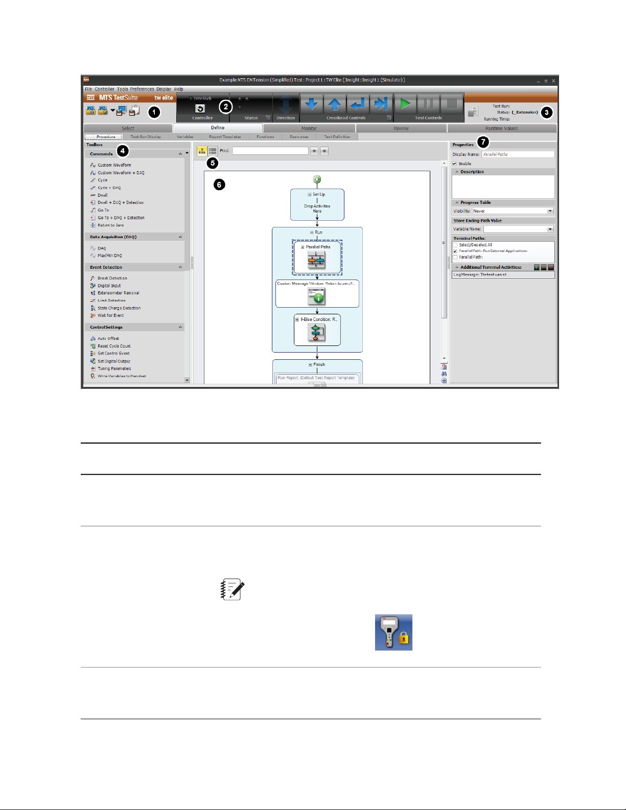
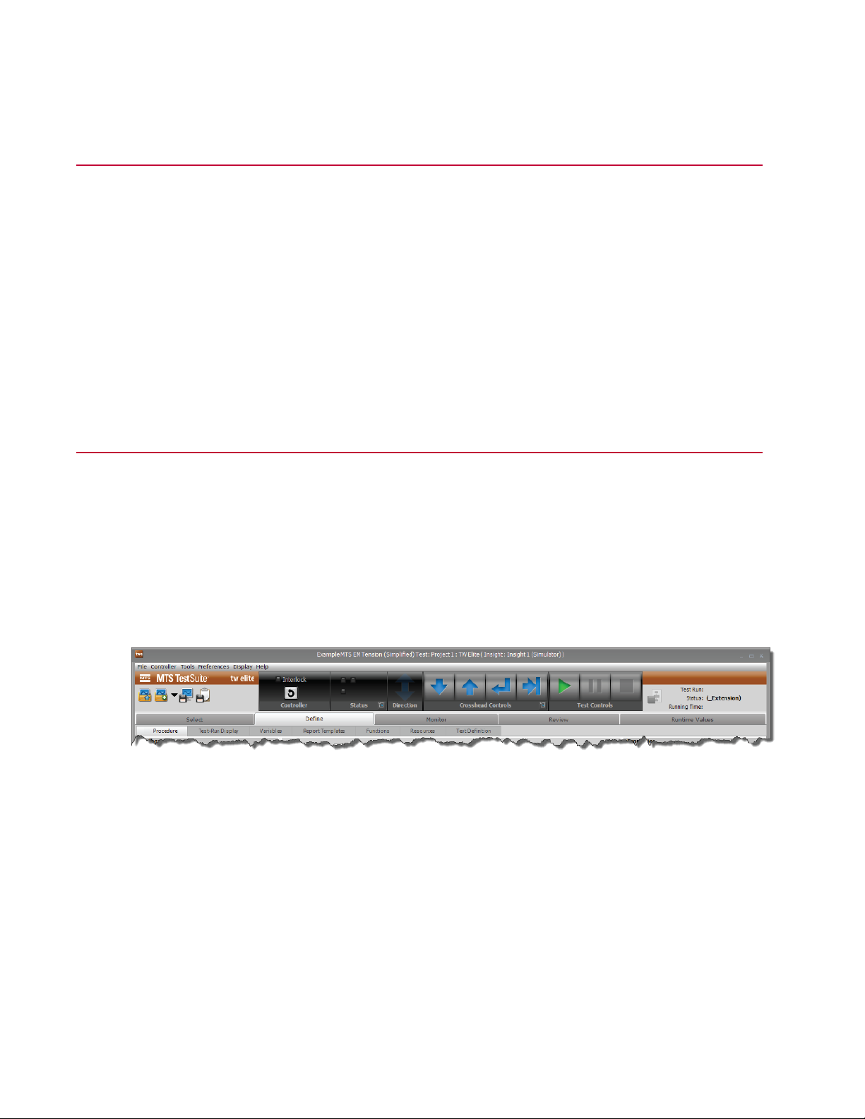
TWE Application Main Window
TWE Main Window Description
DescriptionItemNumber
1
Menu bar and
Quick Access
panel
Control panel2
Status panel3
Provides menus and quick-access icons that allow you to perform tasks
such as opening tests, opening tests from templates, and saving tests
as templates.
Allows you to resolve interlocks; display fault status; view the direction
in which the crosshead is moving; position the crosshead; and start,
stop, and hold the test.
Note: When control is provided by a handset, the crosshead
controls will be locked and overlaid by the handset exclusive
control icon:
Shows test run information, including name, status, and running time.
This panel includes a control that allows you to terminate the current
test run.
18 | MTS TestSuite
Page 19

Introduction
DescriptionItemNumber
4
Toolbox panel (not
shown)
Outline button5
Workflow6
The contents of the Toolbox panel change depending on the subtab
selected in the Define tab:
• When you select the Procedure subtab, the Toolbox panel contains
components that pertain to test activities such as commands, data
acquisition, test flow control, and program actions.
• When you select the Test-Run Display subtab, the Toolbox panel
contains components that pertain to the display of test data, such as
cycle, variable, and signal views.
The Outline button displays a hierarchical view of the test in the center
panel when selected.
Provides a work area to edit tests. You drag test activities from the
toolbox to the workflow to edit tests. The workflow contains three
sections: Set Up, Run, and Finish.
• Use the Set Up section for activities that you want to perform before
you start test runs, such as configuring the load train (setting up
fixtures, etc.) and entering a test name. The Set Up section runs only
once when you start a test, that is, before the first test run in the test.
• Use the Run section for applying forces to the specimen while
performing test runs. The Run repeats for all test runs in the test,
and by default shows the Review tab after every test run.
If you are using a multi-head frame and template, your workarea will
show a Multi-Head Run section instead of a Run section. For more
information about the Multi-Head Run section, see About the
Multi-Head Run Section (p. 21).
• Use the Finish section for operations such as printing reports,
exporting files, saving test data, and archiving. The Finish section
runs when the number of test runs set for the test is complete, or
when the operator clicks the Run Finish Section button on the Review
tab.
Note:
The workflow includes Pan and Zoom features to help you
view complex test procedures.
Properties panel7
Allows you to define or change the information, characteristics, and
appearance of the selected procedure activities and runtime display
components. For example, you can use the Properties panel to change
the amplitude of a cycle command test activity in a procedure, or the
Y-axis signal selection on a signal scope in a test-run display.
MTS TestSuite | 19
Page 20
Introduction
Main Window Toolbar
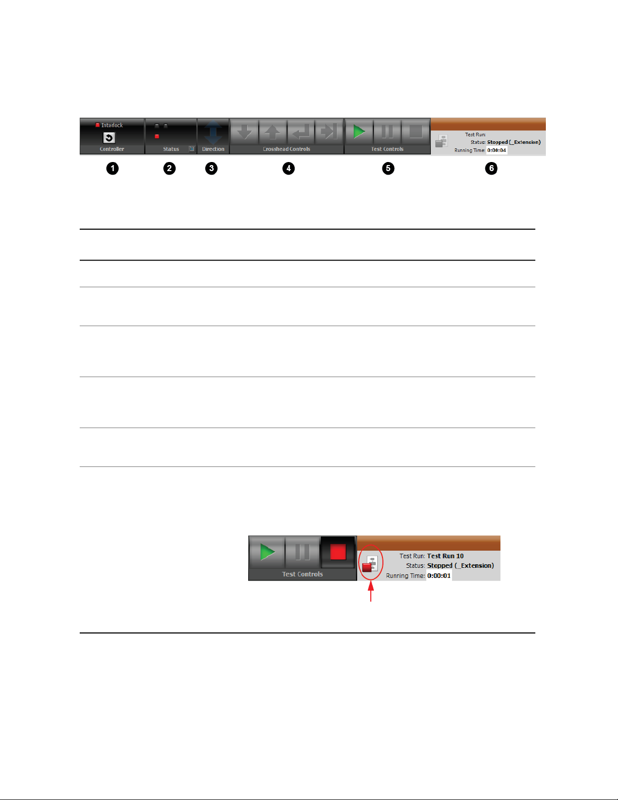
TWE Application Main Toolbar
Application Toolbar Description
DescriptionItemNumber
Allows you to reset interlocks.Controller panel1
Status panel2
Direction panel3
4
5
Crosshead
Controls panel
panel
Shows fault status information. This indicator is primarily for diagnosing
system errors with MTS service personnel.
Indicates when the crosshead/actuator is moving and in what physical
direction. This relates to physical motion, regardless of whether feedback
is increasing or decreasing.
Contains controls that allow you to move the crosshead up and down
for specimen installation, and for returning the crosshead to the zero or
a preset location.
Contains controls to run, hold, and stop the test run.Test Controls
Shows test run information, including name, status, and running time.Status panel6
It includes a Cancel Test Run button you can use to terminate the current
test run. When the test is stopped, pressing this button terminates the
current test run. Pressing the Run button starts a new test run.
20 | MTS TestSuite
Status Panel with Cancel Test Run Button
Page 21
About the Multi-Head Run Section
Introduction
Note:
The Multi-Head option is a separately licensed feature.
Note:
Prerequisite: Only analog data is collected from the multiple active load cells in a multi-head frame.
You must have National Instruments Data Acquisition (Ni-DAQ) hardware and software or an
extensometer installed which will convert the analog data to digital signals.
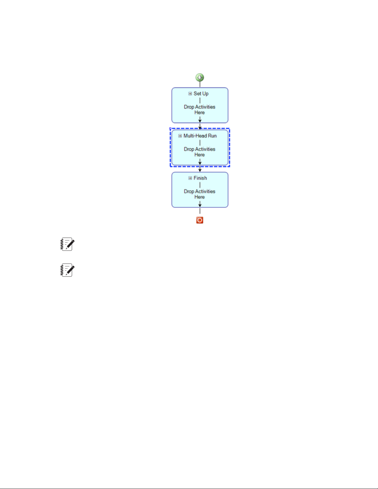
Multi-head frames can contain up to five active load cells which allow the simultaneous collection of test-runs
for multiple specimens. By default, the test run collects the results for all specimens within one file. You
can create a separate test-run file for each of the specimens by using the appropriate multi-head template
which contains the Multi-Head Run section in the test procedure work area. This section is similar to the
Run section found in templates for single head frames which contains activities for applying forces to the
specimen while performing test runs. Unlike the Run section, the Multi-Head Run section contains a
Properties Panel where you can input configuration data. The Multi-Head Run is only run once. Data is
collected simultaneously from the Ni-DAQ analog signals. After the test is completed, the data is split into
multiple tests runs. At the end of the test, a number of test runs will be created and populated with the
collected data. The new test runs appear post-test as if they were individually collected.
At the end of the multi-head test, the array data is split into multiple test-run files by moving the collected
data into the normal force, extension, and optional strain variables.
To create a new multi-head template, you must start with an existing test or template that contains the
Multi-Head Run section. To save a test as a template, you must be assigned the Administrator or Engineer
privilege.
MTS TestSuite | 21
Page 22
Introduction
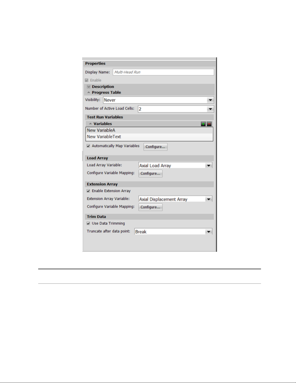
Multi-Head Run Section Properties
Number of Active Load Cells
22 | MTS TestSuite
Multi-Head Run Section Properties
DescriptionItem
Specify how many test-runs should be created. For example, if you are
testing four specimens, enter 4. When the test run has ended, four test
run files will be created. Default: 5
Click the Automatically Map Variables checkbox to have the system
map variables, or click the Configure button to open the Map Variables
window and manually map variables.
Page 23

DescriptionItem
Note:
If you select the Automatically Map option and then change the
Number of Active Load Cells value, some variables will be
created or removed.
If you map variables manually, and then select Auto Map
Variables, your manually created variables will be overwritten
by the automatically-generated variables.
Introduction
Test Run Variables
Load Array Variable
Enable Extension Channels
Trim Data
Specify variables that are not in the Common category. For example,
if Number of Active Load Cells is 5 and the Width variable is added
to this list, the other five variables should be mapped to the Width
variable (such as Width1, Width2… Width5). At the end of the test, the
variable values from Width1, Width2, and so on, must be moved to the
Width variable in the appropriate test runs. Click the green plus sign to
add a variable. To delete a variable, select a variable in the list and click
the red minus sign.
Click the Configure button to open the Map Variables window.
Specify the name of the array variable that is used to gather data from
the Force (Load) channel. Map it to the other array variables as
described above in the Test Run Variables description. At the end of
the test, the variable values from mapped arrays must be moved to the
selected Load Array variable in the appropriate test runs. Click the
Configure button to open the Map Variables window.
Select to map additional array variables to the other array variables.
You can also move data from mapped variables to the selected array
variable at the end of the test. Click the Configure button to open the
Map Variables window.
Select to have the trimming process performed after the data has been
split into test-run files. The trimming process will keep the point identified
by the variable. In other words, the data will be trimmed at the variable
index plus one. If the variable is invalid, no truncation will take place
and a message will be logged. Default for Truncate after data point:
Break
MTS TestSuite | 23
Page 24

Page 25

Examine the Example Test
Topics:
•
About this Chapter.............................................................................................................................26
•
Design Flow.......................................................................................................................................26
•
Define Tab.........................................................................................................................................27
•
Monitor Tab........................................................................................................................................49
•
Review Tab Layout............................................................................................................................51
•
Runtime Values Tab..........................................................................................................................57
MTS TestSuite | 25
Page 26
Examine the Example Test
About this Chapter
This chapter provides a detailed review of the example test provided with the TWE application.
You will examine the test’s workflow, test activities, use of variables, and so on. Understanding how the
example test was created with the TWE application and how the test appears in the interface will help you
understand how to create tests of your own.
Modify the Example Test (p. 81) provides a tutorial for modifying the example test for a different scenario.
For More Information
Start TWE and Open the Example Test (p. 17)
Modify the Example Test (p. 81)
Design Flow
The flow for designing tests with TWE is defined by the tabs shown on the main display after you open a
test:
• Select tab (or the initial open test/template window)
• Define tab
• Monitor tab
• Review tab
Main Tabs in TWE
Select tab
Use the initial open test/template window or the Select tab to choose an existing test or template to modify.
Define tab
Use the Define tab to modify the selected test by modifying the workflow, editing variables, applying
functions, and so on.
26 | MTS TestSuite
Page 27

Examine the Example Test
Note:
When operators use TWX, tests typically open to the Monitor tab so operators can review pretest
variables before performing test runs. However, if the selected test has validation errors, the test
opens to the Define tab so operators can use the Resource subtab to resolve resource conflicts.
Monitor tab
Use the Monitor tab to review pretest variables (inputs that typically apply to all of the test runs in the test)
shown to the operator. You may create additional pretest variables by editing variable properties in the
Variables subtab of the Define tab.
Review tab
Use the Review tab to view test results, customize table and chart content, define markers, and customize
report templates with the Reporter Add-In for Microsoft Excel.
Runtime Values tab
Use the Runtime Values tab to view current variable values and activity configuration values.
Define Tab
You perform most test design tasks on the Define tab, which includes the following subtabs:
• FitProcedure
• Test-Run Display
• Variables
• Report Templates
• Functions
• Resources
• Test Definition
Outline View in the Procedure Subtab
When a test is opened in TWE, the Define tab and Procedure subtab are displayed by default. You can
select Outline view by clicking the Outline button. The Outline view shows the procedure as a hierarchy.
MTS TestSuite | 27
Page 28
Examine the Example Test
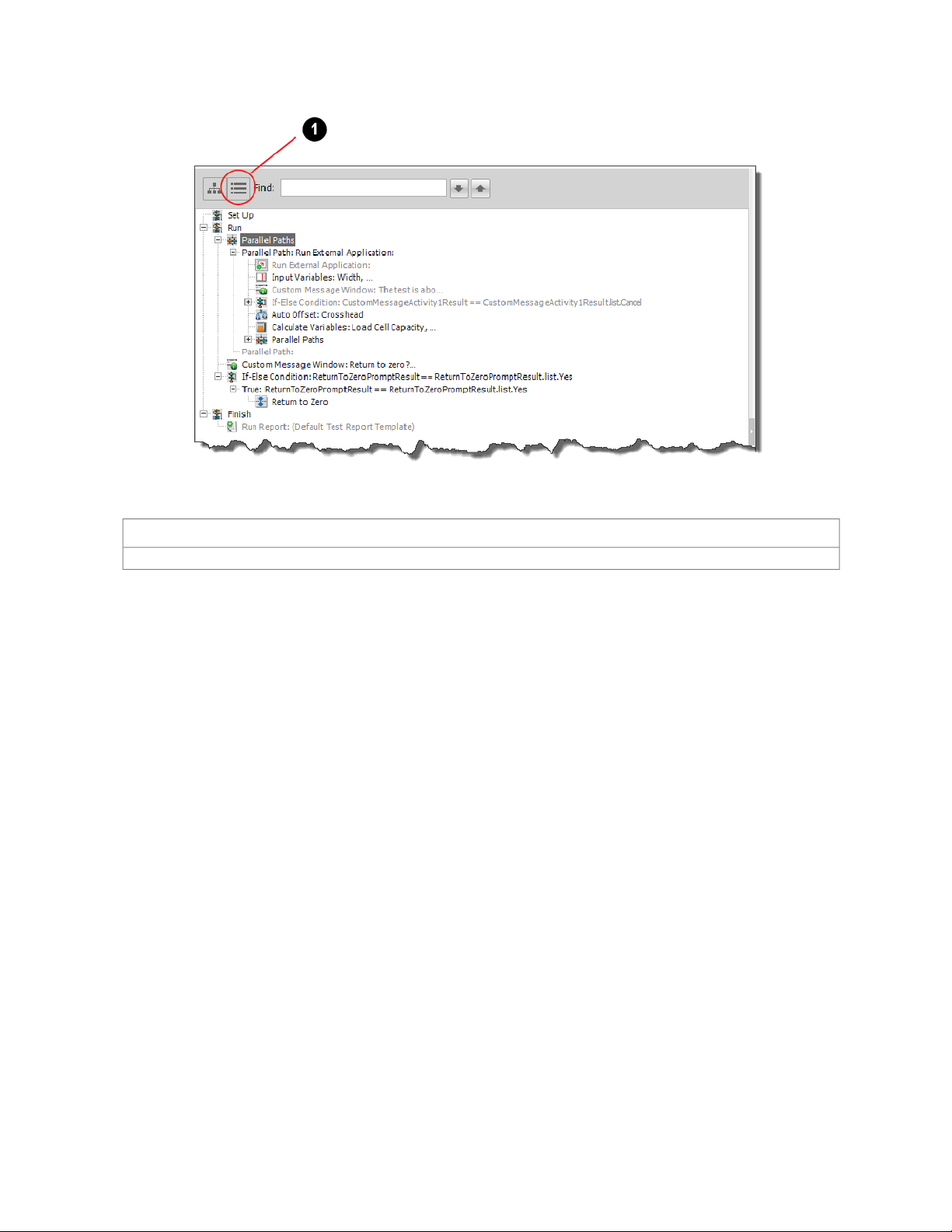
Outline View and the Find Feature
DescriptionItem
Outline button1
Tip
The Find feature is particularly useful for locating activities nested within other activities. For instance, to
locate the Go To + DAQ + Detection command activity in the example test, enter Go To and press return.
The outline hierarchy expands to show the Go To + DAQ + Detection activity, and the activity is highlighted
in the workflow.
Workflow in the Procedure Subtab
The center of the main window shows the workflow. The workflow consists of a sequence of connected
activities divided into test sections; it is a graphical representation of the test.
Each section performs a specific function within the test.
28 | MTS TestSuite
Page 29
Examine the Example Test
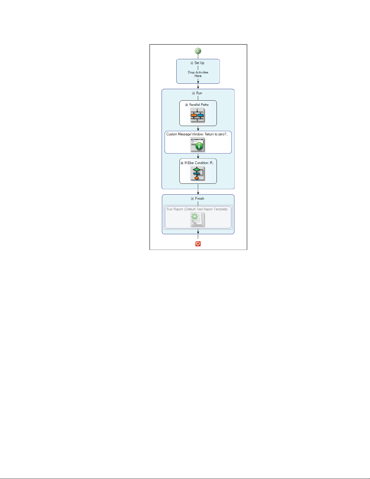
Workflow of the Example Test
All TW tests include the following sections:
• Set Up
• Run
• Finish
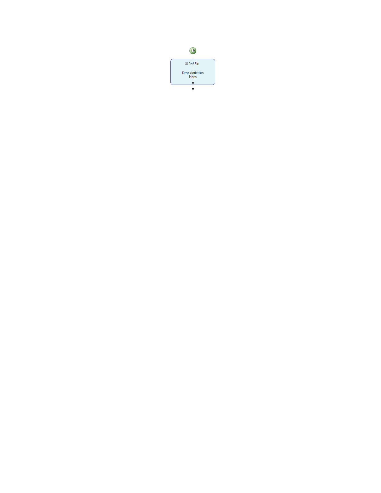
Set Up Section
The Set Up section runs only once before the first test run. Since there are no activities in the Set Up
section of the example test, the Set Up section is skipped and the Run section begins immediately.
You typically use this section for activities that you want to perform before you start test runs, such as
configuring the load train (setting up fixtures, and so forth) and entering a test name.
For more information about activities, see Modify the Example Test (p. 81).
MTS TestSuite | 29
Page 30
Examine the Example Test
Set Up Section of the Example Test.
For More Information
Modify the Example Test (p. 81)
Run Section
The Run section performs a test run when the operator clicks the Run button. After each test run, the
Review tab appears, which shows test data in tables and charts.
The Run section of the example test has been performed three times, so the Review tab includes data
from three test runs.
30 | MTS TestSuite
Page 31

Examine the Example Test
Note:
The following figure shows the top Parallel Path activity in the Run section expanded.
Run Section of the Example Test
MTS TestSuite | 31
Page 32

Examine the Example Test
DescriptionNumber
Parallel Path activity: left branch.1
Parallel Path activity: right branch (disabled).2
If-Else activity (disabled).3
Custom Message activity (disabled): “The Test is About to Start”.4
Input Parameters activity.5
Parallel Path activity in left branch of (1).6
Custom Message activity: “Return to Zero”.7
For More Information
Review Tab
Run Section Description
Examining the Logic in the Run Section
The left branch of the parallel path (1) supports the normal test flow. The right branch (2) exists to support
the Cancel function associated with the If/Else activity (3) that follows the Custom Message (4) activity.
Default behavior
By default, the If/Else (3) and Custom Message (4) activities are disabled. So when you run the test, no
prompt appears to inform you that the test is about the begin, and that you can choose to cancel.
Because of this, when you run the test you are prompted for specimen dimensions per the Input Parameters
activity (5), and then the Test-Run Display tab shows a graph as the Go To + DAQ + Detection activity
performs a ramp. The Go To + DAQ + Detection activity is nested within the Parallel Paths activity (6).
(The Auto Offset and Calculate Variables activities run before the Parallel Paths activity, but do not
affect the interface.)
When a break is detected, the ramp stops and you are prompted to return to zero when the next Custom
Message activity (7) executes.
Behavior with the If/Else and Custom Message activities enabled
If the If/Else and Custom Message activities (3 and 4) are enabled, when you run the test, a prompt
appears to inform you that the test is about the begin, and that you can choose to cancel.
If you choose to cancel, the test logic uses the right side of the Parallel Path activity (2) to skip the ramp
command in the Go To + DAQ + Detection activity nested in the Parallel Paths activity (6). Next, the
Custom Message activity (7) prompts you to return to zero.
32 | MTS TestSuite
Page 33

Examine the Example Test
Program Command in the Example Test
In the example test, program command is issued from the Go To + DAQ + Detection activity nested within
the second Parallel Paths activity in the Run section. This is the only activity in the example test that
applies forces to the specimen.
Branches in the Parallel Activity
Description of Branches in the Parallel Activity
DescriptionItem
1
2
3
4
Auto Offset and Go To + DAQ + Detection activities. For more
information, see Path for the typical test flow .
State Change Detector activity. For more information, see Path
with the State Change Detector .
Limit Detection activity: Specimen. For more information, see
Path with the Limit Detector for the specimen .
Limit Detection activity: Load Cell. For more information, see Path
with the Limit Detector for the load cell. .
MTS TestSuite | 33
Page 34

Examine the Example Test
DescriptionItem
5
Digital Input Detector activity: Handset Connected. For more
information, see Path with the Digital Input Detector for the handset
.
Branches in the Parallel Paths Activity
The nested Parallel Paths activity in the example test contains five parallel branches. All of the branches
are terminal, meaning the completion of any of the paths ends all of the other paths.
Path for the typical test flow
In a typical test flow, the path that contains the Auto Offset and the Go To + DAQ + Detection activities
(1) ends the other paths when the specimen fails. The Auto Offset activity resets the running time of the
test run to zero, and the Go To + DAQ + Detection activity provides program command.
Path with the State Change Detector
The State Change Detector path (2) detects a stopped test state. If the operator clicks the Stop button
while the Go To + DAQ + Detection activity issues command, the Stop Change Detector activity detects
the stopped state and ends the Parallel Path activity. So if the operator clicks the Stop control while the
system is ramping, the ramp stops immediately and the “Return to Zero?” prompt appears. Because of
this, the operator cannot stop and then resume command in the example test.
Path with the Limit Detector for the specimen
The first Limit Detection activity (3) detects minimum and maximum load values applied to the specimen
while the Parallel Path activity is active. The minimum and maximum values are defined by Load Limit
Low and Load Limit High variables. The action for both limits is set to No Action. This means if either of
the specified values are detected, the detector trips and the Parallel Path activity ends.
This activity protects the specimen by allowing you to define the maximum compressive and tensile forces
applied to the specimen while the command is applied.
Path with the Limit Detector for the load cell
The second Limit Detection activity (4) detects the maximum load value you wish to apply to the load cell
while the Parallel Path activity is active. The maximum value is defined by Load Cell Capacity variable.
The Action is set to No Action, which means if the specified value is detected, the Parallel Path activity
ends.
This activity protects the load cell by allowing you to define the maximum compressive force applied to
the load cell while command is applied.
Path with the Digital Input Detector for the handset
The Digital Input Detector activity (5) detects a transition from low-to-high in the DI/O port associated
with the handset while the Parallel Path activity is active. The Action is set to No Action, which means if
the transition is detected, the Parallel Path activity ends. When the handset is connected, the DI/O port
is biased high.
This activity stops the command if the handset cable is disconnected while command is applied.
34 | MTS TestSuite
Page 35

Examine the Example Test
About detector action resources
Actions are test resources. By default, the only action available to the detectors in the example test is No
Action. The MTS Insight controller also supports Program Hold, Program Stop, and Interlock actions, but
these actions have been removed from the test because they are not used.
About restoring detector actions
You can restore unused controller resources to tests by importing them with the controls in the Resources
tab (Define tab > Resources subtab). In Modify the Example Test (p. 81), you will restore all controller
actions to the example test.
For More Information
Modify the Example Test (p. 81)
Go To + DAQ + Detection Activity
This composite activity performs multiple functions associated with the following tabs:
• Go To
• DAQ
• Limit Detection
• Break Detection
• Wait for Operator Action
For most tests, including the example test, the command content of the test is provided by one or more
Go To + DAQ + Detection activities in the Run section.
Go To tab
The Go To tab is configured to ramp the crosshead at a rate defined by the Test Rate variable. The
Termination Condition on this tab is not enabled, so the ramp is configured to continue until a specimen
failure is detected by the condition specified in the Break Detection tab. If that condition is not detected,
the ramp continues until one of the other branches of the Parallel Branch activity (such as a limit detection
branch) completes.
MTS TestSuite | 35
Page 36

Examine the Example Test
Go To Tab and Edit Variables Window
DAQ tab
The DAQ (data acquisition) tab is configured to continuously acquire timed load (force) and crosshead
(length) data at a sample rate defined by the Data Acquisition Rate variable. It is also configured to map
acquired data to array variables.
36 | MTS TestSuite
Page 37

Examine the Example Test
DAQ Tab, Trigger Properties Window, and Map Variables Window
About mapping data to variables
In all MTS templates created for TW, the Save data to variables? control is enabled by default. Mapping
data to arrays significantly extends the functionality of TW. Array variables provide the data in the charts
and tables in the Review tab, support the use of several types of test-run displays (for example, the
Array-Variable Chart, the Variable Data Table, and the Variable Meter), and support the use of the Reporter
Add-In for Microsoft Excel.
Limit Detection tab
Limit detection is not used in this tab in the example test. For more information about limit detection, see
Set Station Detector Limits (p. 110).
Break Detection tab
The Break Detection tab detects when the specimen breaks while the Parallel Path activity is active.
The break detector monitors the peak load applied to the specimen. When the current value exceeds the
value defined by the Break Threshold variable, the detector is armed.
MTS TestSuite | 37
Page 38

Examine the Example Test
When the detector is armed and the peak load value drops by the percentage defined by the Break
Sensitivity variable, a break is detected. The action is set to No Action. This means if a break is detected,
the detector trips and the Parallel Path activity ends.
For many types of tensile tests, the test run completes when the specimen fails and the break detector
trips.
Break Detection Tab
Wait for Operator Action tab
The Wait for Operator Action tab enables the operator to click a button shown on the Monitor tab while
the test run is being performed. Clicking this button prematurely ends the Parallel Path activity.
The button label shown on the Monitor tab is determined by the text entered in the Display Text box.
In the example test, the button is labeled Next Segment. When the operator clicks the Next Segment
button on the Monitor tab while the test is running, program command stops and the "Return to Zero?”
message is shown.
38 | MTS TestSuite
Page 39

Examine the Example Test
Wait for Operator Action Tab and the “Next Segment” Button Shown on the Monitor tab
Finish Section
The Finish section runs:
• Automatically, when the Maximum Test Runs variable equals the number of test runs performed, or
• Manually, when the operator clicks the Run the Finish Section button on the Review tab toolbar. The
Review tab appears automatically after each test run.
In the example test, the Maximum Test Runs variable is set to 9999 (default), so it is designed to be ended
manually.
The Finish section is typically used for operations such as printing reports, exporting files, saving test data,
and archiving.
The example test contains only a disabled Run Report activity, so no activities are performed when running
the Finish section.
Finish Section of the Example Test
MTS TestSuite | 39
Page 40

Examine the Example Test
Run the Finish Section Button on the Review Tab
Test-Run Display Subtab
When you click on the Test-Run Display subtab of the Define tab, the center of the main window shows
the designer view of the test-run displays used in the test. You can think of a test-run display as a readout
device—like a meter or scope—that shows test signals or other information on the Monitor tab during test
runs.
The only test-run display used in the example test is the Array-Variable chart. It uses the Load variable
for the Y-axis and the Extension variable for the X-axis, as shown on the Properties panel.
You can add any of the test-run displays in the Toolbox to the test to view test information during test runs.
Array-Variable Chart on the Test-Run Display Subtab
Variables Subtab
When you click on the Variables subtab of the Define tab, the main window shows the variables used in
the test.
40 | MTS TestSuite
Page 41

Examine the Example Test
Variables Subtab and Variable Availability Property
Variable Definition
A variable is a place with a name in which you can store one or more values. Variable types and examples
used in the test include:
• Simple variables (also referred to as scalar variables) store either a value or a string. In the example
test, the variable used to set the rate at which data is acquired is a simple variable. It has a display
name of Data Acquisition Rate, an internal name of DataAcqRate, and default value of 10 Hz.
• Array variables store an array, which is an ordered collection of numbers or strings. You can refer to
individual values in an array by specifying an index. In the example test, the variable used to store
acquired load data is an array variable. It has a display name of -Load, an internal name of _LoadArray,
and a default value of 0.000 kN (array variables resize automatically, so you can disregard the default
value).
• Calculated variables are variables (simple or array) that include a mathematical expression. In the
example test, the variable used to store stress data is a calculated variable. It has a display name of
Stress, an internal name of _StressArray, a default value of 0.000 kN/mm, and a calculation of
_LoadArray/Area.
Variable Use in the Example Test
Variables are used extensively in the example test. While using variables is not a requirement for test
design, using variables significantly extends the functionality of tests created with MTS TestSuite software.
If variables were not used in the example test:
• To change the properties of activities that are currently variables, you would have to navigate through
the layers in the workflow and locate specific property fields.
MTS TestSuite | 41
Page 42

Examine the Example Test
• You could not use the array-variable chart on the Test-Run Display subtab, or any of the other test-run
displays in the Variable Views category (or other test-run displays that use variables). You would only
be able to use test-run displays in the Signal Views category, such as signal meter and signal scope.
• The charts and tables in the Review tab, which are based on variables, would not contain useful
information.
• You would not be able to show test data in charts and graphs using the Reporter Add-in for Excel. In
this case, test data would be available only as tables of sampled signal data values.
Variable Availability Attributes
Variables have one or more of the following Availability attributes:
• Pretest
• During Test
• Editable Post Test
• Results
The Pretest, During Test, and Editable Post Test attributes specify when the operator can change the
variable during the test.
Pretest attribute
Variables with this attribute can be edited before the test is initialized and before each test run. In the
example test, the Data Acquisition Rate, Test Rate, and Grip Separation variables have this attribute. They
appear on the Monitor tab before the test is started and each time the operator clicks the Run button.
During Test attribute
Variables with this attribute can be edited in any of the test sections (Set Up, Run, or Finish) after the test
is started. In the example test, the Input Parameters activity in the Run section prompts the operator for
the width and thickness of the specimen, which apply to the Width and Thickness variables.
Editable Post Test attribute
Variables with this attribute can be edited in the Variables table on the Review tab after the test is complete
(1). The Variables table does not appear by default. To view the Variables table, you must change the
default panel view on the Review tab by clicking the Two or Four-Panel Views button (2). In the example
test, the Break Index variable has this attribute (3).
42 | MTS TestSuite
Page 43

Result attribute
Examine the Example Test
Access to the Variables Table and Editable Post-Test Variables
The Result attribute specifies the variables that appear in the Result table and Variables tables in the
Review tab. In the example test, the Peak Load variable has the Result attribute, and appears on the
Results table.
Peak Load Variable on the Result Table
Variables with both Results and Editable Post Test attributes
Some variables include both Editable Post Test and Result attributes. In the example test, this applies
to the Thickness variable. In this case, the variable appears in two locations on the Review tab:
• In a non-editable form in the Results table
• In an editable form in the Variables table (appears when you select a multi-panel view)
Report Templates Subtab
The Report Templates subtab shows the report templates available to the example test. Report templates
are Microsoft Excel files that specify what and how test information appears in generated reports. Report
templates are workbook files (.xltx); you can generate reports without Excel installed. Excel must be installed
to create or modify report templates.
MTS TestSuite | 43
Page 44

Examine the Example Test
Reports Templates Subtab
Default Test-Run Report template
Use the default Test-Run Report template for generating reports for individual test runs. The example test
does not include an activity in the workflow to generate a report for test runs. However, the operator could
generate a report for test runs using the toolbar controls on the Review tab.
Default Test Report template
Use the default Test Report template for generating reports that apply to all the test runs in the test. The
example test includes a disabled Run Report activity in the Finish section of the workflow. To generate a
test report, the designer would have to enable this activity. Otherwise, the operator could generate a test
report using the toolbar controls on the Review tab, as shown
Generate Reports Buttons on the Review Tab
Functions Subtab
The Functions subtab shows the custom functions available to the example test. The MTS TestSuite TW
application uses functions to perform complex mathematical operations during tests.
Functions Subtab
The example test includes the SimulatedLoad function, which derives load data from extension data
provided by the MTS Insight Controller simulator. This function was created with Python. To view the
Python code for this function (as shown), select the function and click Edit, or double-click the function.
44 | MTS TestSuite
Page 45

Examine the Example Test
Using Python with MTS TestSuite
Python is an interpreted, general-purpose, high-level programming language with an extensive resource
library. You can use Python to create custom functions to extend the functionality of MTS TestSuite software.
You can use Python for reading and writing to files, dynamic mathematical calculations, and manipulating
variables.
Python Code for the SimulatedLoad Function in the Function Editor
Resources Subtab
The Resources subtab of the Define tab shows the mapping of test resources to controller resources.
Note:
The information in this section applies to using the TWE application with MTS Criterion frames and
MTS Insight controllers.
Resources Subtab (Default)
MTS TestSuite | 45
Page 46

Examine the Example Test
Resources Tab Description
DescriptionNumber
Connection indicator1
Test resources2
Controller resources3
Resource management controls4
Controller identification
The connection indicator (1) shows the controller configuration associated with the current test when TW
is connected to a controller. In the example test, the controller configuration is labeled “C42.503 (Simulator)”.
The main window shows the test name, project, application name, controller name, and controller
configuration. In the example test, this is:
“Example MTS EM Tension (Simplified) Test: Project 1: TW Elite (Insight:C42.503 (Simulator))”.
Test resources
The resources in (2) are test resources. Test resources are required by the test and must map to equivalent
resources in the Controller Resources column when connected to a controller.
In the example test, the control mode labeled “Crosshead” is a test resource. You can use test resources
for various test elements, such as activities, runtime display devices, and variables.
Controller resources
The resources in (3) are controller resources. A controller resource refers to a hardware resource in the
controller as it appears in the controller configuration. In the example test, the control mode labeled
“_Extension” is a controller resource.
When connected to a station, controller resources reflect the resources in the controller configuration.
When not connected to a controller, controller resources are the resources TWE expects to find when
connected to a controller.
Managing resources
Resource management controls (4) allow you to add, import, delete, and rename test resources.
It is important to understand that only the controller resources required by the test are typically shown on
the Resources subtab. To view all of the resources available in the connected controller, click Import
Resources... > Import All Unused Controller Resources.
In the example test, the default Resources subtab shows just one control mode resource; when all unused
resources are imported, it shows multiple control modes, as shown.
46 | MTS TestSuite
Page 47

Examine the Example Test
Resources Subtab with Imported Resources
Resource mapping
A test resource is not required to have the same name as the equivalent controller resource. For instance,
in the example test, the control mode test resource is labeled “Crosshead”, and the equivalent controller
resource is labeled “_Extension”.
However, if the names are different when TWE connects to the controller, you must map the test resource
to the equivalent controller resource.
Suppose you disconnect the example test from the controller and reconnect to a different controller in
which the equivalent resource is labeled “_Displacement”. In this case, TWE would be unable to
automatically map the new controller resource “_Displacement” to the test resource “Crosshead”, and a
validation icon would appear in the window.
To resolve the error, you would have to manually map the controller resource to the test. To do this, you
would click the list icon next to the “_Displacement” test resource and select “Crosshead”.
Resource mapping is saved with the test.
Note:
When you create tests while the TWE application is connected to a controller, it is referred to as
“online” test design. You can also perform “offline” test design.
Test Definition Subtab
The Test Definition subtab of the Define tab shows general settings for the test, including:
• The Formula Assistant File
• The Log Type, which determines whether an audit trail is created for the test.
• Whether the test can be started remotely with a digital input.
• Whether the display automatically switches to the Review tab at the completion of a test run.
MTS TestSuite | 47
Page 48

Examine the Example Test
Note:
All fields are read-only until you click the Edit button.
Formula Assistant File
Test Definition Subtab
The Formula Assistant File provides a base set of system variables, calculations, and functions associated
with a specific type of test. The example test uses a formula assistant file labeled “Electro-Mechanical
Formula Assistant”.
If you need to change the Formula Assistant File associated with a template, contact your MTS Field
Service Engineer for assistance.
When a test variable is associated with the Formula Assistant File, an Option list becomes available in
the Calculation panel for the variable. The options available depend on the selected variable.
For example, when you select the Area variable on the Variables subtab of the Define tab, several
specimen geometry types are available in the Options list.
Log type
The log type selections include Basic or Audit Trail. The example test uses the Basic log type.
The Audit Trail feature is for tracking changes to the test. When selected, each time you run a test on an
MTS Criterion or MTS Insight system, the application writes the TEDS model and serial number to the test
run log. When the test is complete, you can right-click on a test run in the Review tab and validate the raw
data for that test run.
Remote start
This control is disabled by default, and is disabled for the example test.
This control works in tandem with the Digital Input control in the Preferences menu (Preferences >
Configuration > Test > Select additional methods to start the test > Digital Input).
If you enable both controls, you can select a digital input source and specify a transition type to start the
test remotely.
Switching to the Review tab
This control is enabled by default, and is enabled for the example test.
48 | MTS TestSuite
Page 49

Examine the Example Test
If you disable this control, the display remains on the Monitor tab after each test run instead of automatically
switching to the Review tab.
For More Information
Changing the Specimen Geometry (p. 84)
Monitor Tab
Monitor tab view before the test starts
Before the operator starts the test by clicking the Run button, the Monitor tab shows the pretest inputs
the operator can change.
In the example test, this includes the Data Acquisition Rate, Test Rate, and Grip Separation variables, as
shown.
Monitor Tab Before the Test Starts
Test opens to Monitor tab for operators
If you open a test while logged on to TWE as an Operator, or when you open a test with the TWX application,
the workflow is hidden, and the main window shows the test inputs on the Monitor tab. If the test contains
validation errors, it opens to the Resource subtab of the Define tab so the operator can resolve the errors.
Editing pretest inputs on the Variables subtab
You can edit the pretest inputs that are shown to the operator in the Variables subtab of the Define tab.
To view variables that have the pretest attribute, use the Column Chooser to add the Pretest column to
the table, then edit as desired in the Availability panel.
MTS TestSuite | 49
Page 50

Examine the Example Test
DescriptionNumber
Edit Pretest Inputs
Description of Variables Tab
Click this icon to display the Column Chooser.1
Select Pretest in the Column Chooser2
Pretest attribute appears in the table.3
Monitor tab view after the test starts
After the operator starts the test, the Monitor tab shows test information on the test-run display included
in the test design until the test run is complete. In the example test, the Array-Variable Chart is used, as
shown.
50 | MTS TestSuite
Page 51
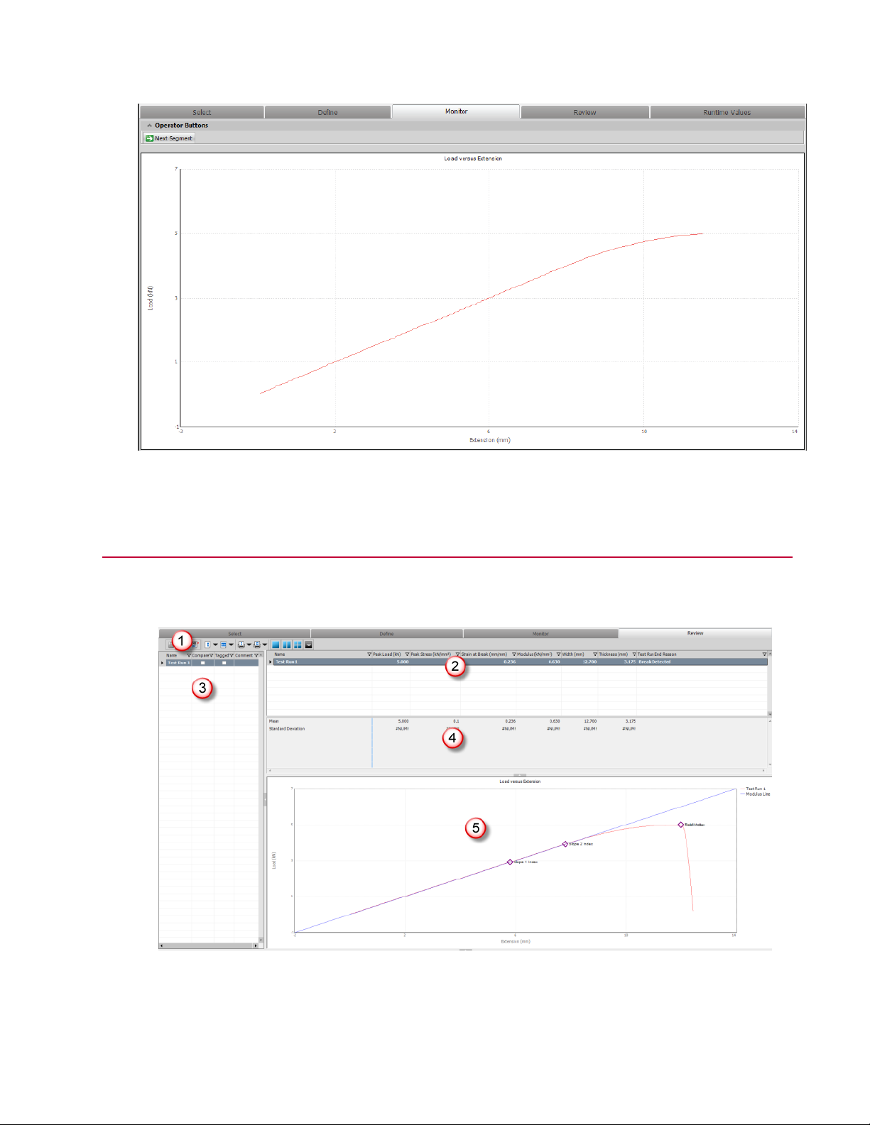
Monitor Tab During a Test Run
Examine the Example Test
Review Tab Layout
The Review tab displays after a test run ends showing test run statistics, charts, and so on.
Review Tab Layout
MTS TestSuite | 51
Page 52

Examine the Example Test
Review Tab Description
DescriptionItemNumber
Toolbar1
Test run results table2
3
Test run information
table
Test statistics table4
Graph5
Provides icons that allow you skip to the activities in the Finish section
of the test, revert and recalculate variables, generate and print reports,
and configure and save the layout of the Review tab.
Shows test results from individual test runs, allows you to compare
one test run to another, and allows you to exclude (referred to as
tagging) individual test runs from statistical computations.
Each test run row in the Results table includes a Compare check box
that controls which test run data appears in the charts and tables.
Shows information about each test run, such as what test run
information is available in the charts and tables on the Review tab,
what test run data is included in calculations, and additional comments
for each test run (if available).
The statistics table shows statistical data compiled from all of the test
runs that are not tagged (excluded). The statistics calculations are
user-defined by right-clicking the statistics area and clicking Configure
Statistics.
The graph shows a graphical representation of test run or test results.
You can add, remove, and edit markers on the graph.
Review Tab Toolbar
The Review tab toolbar contains icons that allow you to show, analyze, and manage test data.
Review Tab Toolbar
Review Tab Toolbar Description
DescriptionItemNumber
1
Revert and Recalculate
Test Run/Test Variables
buttons
The Variables table on the Review tab allows you to create what-if
analysis scenarios by changing test variable values and observing
the test results. The Revert and Recalculate buttons allow you revert
changes that pertain to individual test runs and to the test (which
includes all the test runs in the test).
52 | MTS TestSuite
Page 53

Examine the Example Test
DescriptionItemNumber
2
3
4
5
Run Finish Section
button
Generate a report for
Test Runs/Test buttons
Runs/Test buttons
View buttons
Actions menu6
Runs the Finish section. You may also run the Finish section
automatically by entering the desired number of test runs in the
Maximum Test Runs variable, which has a default value of 9999.
Generates reports that you can open using Microsoft Excel. You
can generate reports that pertain to individual test runs or the test.
You can choose pre-made or customize report templates.
Prints reports generated from individual test runs or for the test.Print a report for Test
Selects the number of panels shown on the Review tab.One, Two, or Four Panel
Note:
The default Review tab shows only the Results table, which
does not show variables you can edit (variables with the Edit
Post Test attribute). To show the Variables table, which
includes variables you can edit, click the Two or Four Panel
View buttons.
Opens a menu where you can save your display layout, open the
Display Manager to work with your displays, and view details about
generated reports in the Reports window.
Test Run Results Table
The Test Run Results table (2) shows the results of each test run. By selecting test runs in the Compare
column, you determine the test-run data that appear in the various charts and tables (3). The variables
listed in the columns of this table are not editable. To view editable variables, you must click the two or
four panel view buttons in the toolbar to display the Variables and Common Variables tables.
Right-click menu for the Test Run Results table
Right-click menus allow you to:
• Select test runs for comparison
• Copy and delete test runs
• Export raw data
• Configure Autotag rules
Export raw data
The Export Raw Data feature allows you to export raw data (sampled from signals versus data mapped
to variables) as tab or comma-delimited text (.txt) files. You can show or manipulate exported data with
other applications, such as Microsoft Excel or Word.
MTS TestSuite | 53
Page 54

Examine the Example Test
Configure Autotag rules
The Autotag feature allows you to create rules that determine when a test run is automatically tagged
(excluded). The Autotag rules are applied as each test run is run or can be defined and applied post test.
Tagging specimens manually
You can manually tag (exclude) test runs by selecting the test runs in the Tagged column. Tagged test
run data is not compiled in the Statistics table.
Statistics Table
The Statistics table (3) contains statistical data calculated from test runs. These calculations include data
from all of the completed test runs that are not tagged (excluded). The example test includes Mean and
Standard Deviation values.
Configuring statistics
You can add additional statistical values to the Statistics table with the Configure Statistics feature on the
right-click menu.
Panel of Charts and Tables
The Charts and Tables Panel (4) displays a chart of the active (highlighted) test run, in addition to the test
runs selected (checked) in the Compare column. For more information about the table and chart views
that can be shown in the Panel, see the MTS TestSuite TW Elite User Guide.
In the example test, the chart in the Panel shows an Array-Variable Chart that plots load versus extension.
It includes the following markers:
• B (Slope 1 Index, or beginning of modulus)
• M (Slope 2 Index, or end of modulus)
• F (Break Index, or point of failure)
• Y (Yield Index, or point of yield)
Note:
In the example test, the F (Break Index) and Y (Yield Index) markers are at the same point, and
the marker symbols are positioned on top of one another.
Chart markers
Chart markers are variables. Each marker on the chart defines a data point in the test run. Chart marker
variables can be defined by either a calculation or the occurrence of a run-time event. In either case, the
marker variable saves an index into a data array. When the marker is added to a chart, its position represents
the X and Y axis values associated with the index.
54 | MTS TestSuite
Page 55

Examine the Example Test
Chart Marker Variable Manipulation
Description of Chart Marker Variable Manipulation
DescriptionNumber
1
2
3
Right-click the M marker (Slope 2 Index variable) and select Edit
Variable.
Use the Edit Variable window to review and edit the marker variable
properties.
You can move the M marker by entering a new value in the
Variables table or by selecting the Move Selected Marker in the
marker right-click menu.
MTS TestSuite | 55
Page 56

Examine the Example Test
Calculated markers
Calculated markers are typically derived from a calculation and are often used in a calculation. For example,
the least squares calculation for the modulus line in the example test uses two calculated marker variables
that appear on a chart. (Marker B, the Slope 1 Index variable; and Marker M, the Slope 2 Index variable).
Using chart variables in test reports
You can add, remove, and edit the markers on the chart. You can also use chart variables elsewhere.
For example, if you add a marker at the maximum load (yield) point on the chart, you can use the X-Y
(load, strain) values associated with that marker in a test report that specifies the maximum load value.
Four-Panel View
The following figure shows the default four-panel view of the example test. Each panel is independent; the
charts and tables do not correspond to one another.
Charts have a right-click menu that allow you to:
• Zoom
• Configure the chart by editing the appearance of trace, curve fit, limit, and axis lines
• Add text
• Add or remove markers
• Copy values and images
• Switch, add, and manage views
56 | MTS TestSuite
Four-Panel View of Review Tab
Page 57

Examine the Example Test
Description of Four-Panel View of Review Tab
DescriptionNumber
1
2
3
4
The Review Chart view in the four-panel view is the same Review
chart shown in the one-panel view. It shows a chart of the active
(highlighted) test run, in addition to the test runs selected (checked)
in the Compare column.
The Review Chart for Multiple Runs view shows a chart of the
selected (checked) test runs, in addition to the active (highlighted)
test run, without markers.
The Variable Table view shows a table of variables of various
categories (except Common) which pertain to the active
(highlighted) test run.
When you select more than one Compare check box on the Test
Run Results table, a drop-down test-run list appears in the
Variables table.
The Common Variable Table view shows a table of variables of
the Common category which pertain to all of the test runs.
Runtime Values Tab
The Runtime Values tab shows and updates variable values in real time while you perform a test run.
Test designers can use the Runtime Values tab to validate their test designs.
When you initially open a test, this tab will not appear on the main window until you run the test.
When you start the test (and when you start each subsequent test run in the test), the display switches to
the Monitor tab. If desired, you can click the Runtime Values tab and monitor the variables values. When
the test run is complete, the display automatically switches to the Review tab.
The figure below shows array-variables updating on the Runtime Values tab during a test run.
MTS TestSuite | 57
Page 58

Examine the Example Test
Runtime Values Tab During a Test Run
58 | MTS TestSuite
Page 59

Design Guidelines
Topics:
•
About this Chapter.............................................................................................................................60
•
Designing Tests.................................................................................................................................60
MTS TestSuite | 59
Page 60

Design Guidelines
About this Chapter
This chapter contains concepts, design considerations, and recommended practices for designing tests
with TWE.
For related procedural information and interface reference, see the MTS TestSuite TW Elite User Guide
installed with the TWE application (Start > Programs > MTS TestSuite > Documentation > TW Elite
User Guide).
For a step-by-step tutorial for modifying the Sample Tension (Simplified) Test, see Modify the Example
Test (p. 81).
This section contains tips and recommended practices.
For More Information
Modify the Example Test (p. 81)
Designing Tests
Recommended
It is not possible to create a test from scratch using the TW application. Choose an existing test or template
that is a close as possible to your desired design and modify as needed.
Tip
The process of test design is iterative. It is good practice to implement your changes iteratively and run
the test after each iteration.
Test Design Checklist
The following table lists the typical order of tasks a test designer may perform to prepare a test for an
operator.
Test Design Tasks
DescriptionActivityStep
Start the TWE application and
1
select a test or template to
customize
Start the TWE application and select a test or template that is
as close as possible to the test you want the operator to
perform. When you open a template, you are actually opening
a test version of the template.
60 | MTS TestSuite
Page 61

Design Guidelines
DescriptionActivityStep
Modify the test2
Select and customize a Test
3
Report template
Run the customized test to
4
validate the design
Save your test as a template5
Deliver your template to the
6
operator
Modify the test by enabling disabled activities within the
template, changing Formula Assistant file options, adding
resources, and editing the workflow.
Create or modify the existing test report template by adding
test variables, etc., from your test run to the template. Editing
report templates requires the optional MTS Reporter Add-In
for Microsoft Excel.
You typically run your test from the operator’s perspective.
You may choose to enhance your test with special operator
information.
When the test runs as desired, you typically save the test as
a template. When the operator opens the template, they will
actually be opening a test version of the template.
When your new template meets your requirements, deliver it
to the operator. The operator can run the template with TWX
or with TWE (you can log on to TWE as an Operator, Engineer,
or Administrator).
Tests and Templates
Choosing a Template to Run or Modify
Locate a template that contains as many of your test requirements as possible.
Open the template (which becomes an editable test when you open it), modify as desired, and test it. Note
that when you run your test to validate the modifications, the application automatically saves the test. Now
save the test as a custom template. When the operator wants to test a batch of specimens, they begin by
opening your custom template, and typically begin the testing of each subsequent batch of specimens by
opening your custom template.
For test inputs, use variables to allow a central definition point for values that exist in multiple areas in a
test.
For test outputs, such as acquired data, use variables to support test reporting. For instance, the data
acquisition activity in the example test is configured to automatically map variables.
File Icons
The following table describes the icons associated with the files that you access in the Open Test, New
Test from Template, and Copy Existing Test window.
MTS TestSuite | 61
Page 62
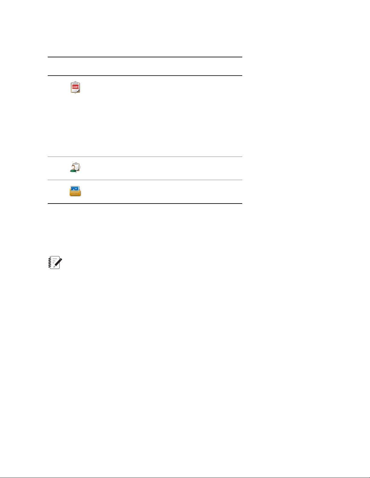
Design Guidelines
File Type Icons
File TypeIcon
MTS Templates—Only the templates for which you
are licensed appear available in the MTS Templates
folders. Templates that are licensed but not
applicable to an application are grayed out.
MTS supplied templates are installed by default in
C:\Program Files\MTS Systems\MTS
TestSuite\Templates.
For 64-bit operating systems, the path is C:\Program
Files (x86)s\MTS TestSuite\Templates.
Custom Templates—Includes any test or template
saved as a template.
Tests—An instance of a template that you can edit
and save as a test or template.
Working with Templates and Tests
When you open a template, you are in an editable copy of the template, referred to as a test file. If you
want to make changes to a template, you must open a test version of the template and save it as a template
(File > Save As > Template) with the same name as the original template.
Note:
You cannot edit MTS-supplied templates.
When you export a test, TW combines the current test and its associated files into one compressed (and
self-contained) file and assigns an extension of .tsproj.
Exported tests can be managed with the Windows operating system. Unexported tests must be managed
within the MTS TestSuite application.
When you save a template, TW compresses the template and assigns an extension of .tstemplate.
Templates can be managed with the Windows operating system.
About running tests from templates
Operators typically begin a new test by opening a template, which becomes a test, and saving the test
with a name that reflects the specimen batch.
62 | MTS TestSuite
Page 63

Modifying Tests
Adding and Configuring Test Activities
Test activity sequence
Test activities execute from top to bottom as they appear on the Test Editor. To execute activities
simultaneously, add Parallel Path activities to the test flow. You can also add While Loop, If-Else
Condition, and Periodic Time Event activities to control the test flow.
Test activity property definition
To define the properties of an activity, select the activity icon on the Test Editor, and then select the
Properties panel. You can choose to define properties as fixed values or variables.
Design Guidelines
Activity Property Example
Error indicators assist property definition
When you add an activity, red error icons appear next to the properties fields when information is missing
or is incorrect.
Example
The example in the following figure shows the error indicators that appear when you initially add a Data
Acquisition activity to the test editor. A similar message also appears in the Error List on the main window.
In this case, all of the error messages disappear when you select a signal and a trigger.
MTS TestSuite | 63
Page 64

Design Guidelines
Error Indicator and Help for the Data Acquisition Activity
Skipping command segments or stopping a test prematurely
When you run a test, the Test-Run Display shows the progress of the test on a chart (such as the
Array-Variable chart used in the sample test). While developing a test, it may not be practical to allow the
entire command to play out while iterating between modifying and running a test.
To speed up iterations, you can use the Wait for Operator Action activity. Place a Wait for Operator
Action activity in a parallel path with the command activity. When you run the test and the command
activity is executing, a button appears on the Test-Run Display that allows you to skip to the next activity.
Wait for Operator Activity in Parallel with a Command Activity
Another option is to add the End Test activity which forces the test run to end before completing all stages
of the activity. When the test procedure reaches the End Test activity, workflow activities that follow and
are parallel to the End Test activity do not execute, and the procedure immediately proceeds to the end
of the test. A message is written to the test run log indicating that the test run was stopped due to the End
Test activity.
64 | MTS TestSuite
Page 65
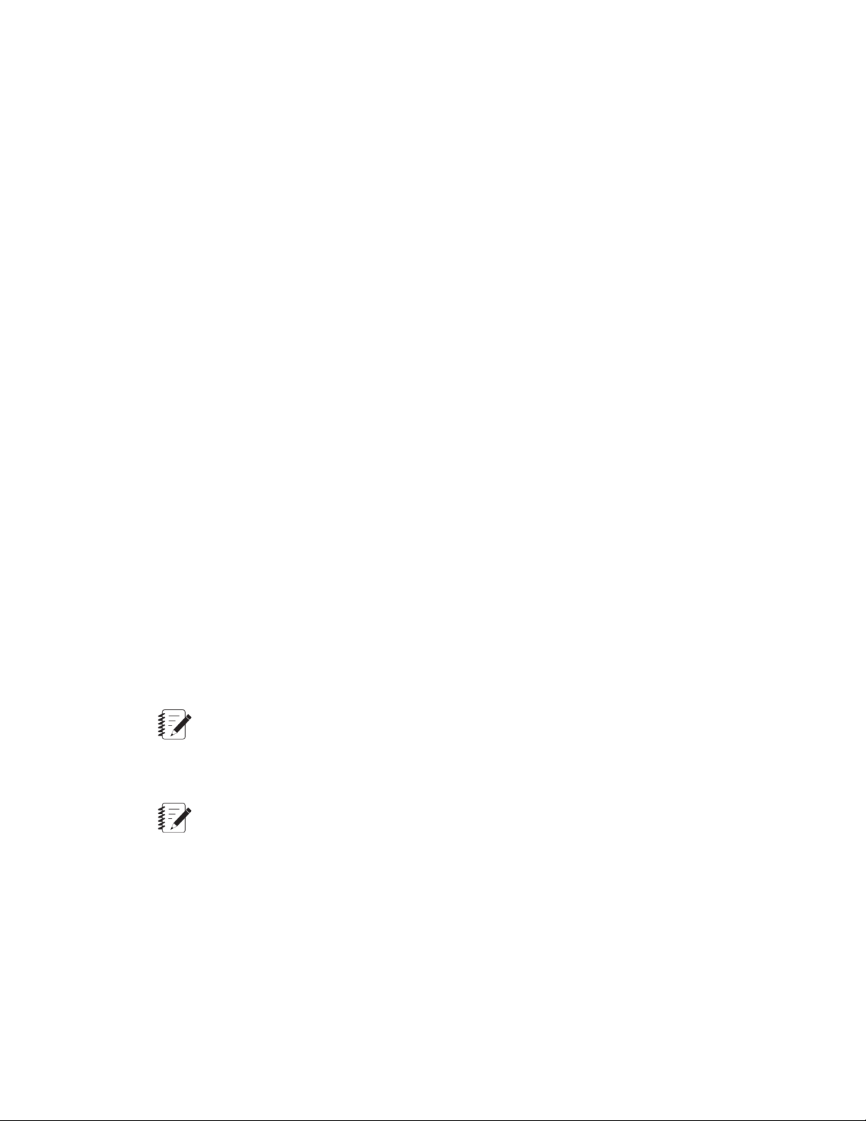
Design Guidelines
Considerations for Test Sections
Set Up section
The Set Up section is for activities you want the operator to perform before test runs begin, such as:
• Entering values for test variables common to all test runs
• Configuring the load train (setting up fixtures, and so forth.)
• Entering the test name, specimen geometry, lot number, batch name, and so forth.
The Set Up section runs only once per test, before the first test run.
Run section
The Run section performs test runs. Operators typically perform the following for each test run:
• Remove the specimen from the previous test run
• Enter values for nominal specimen dimensions
• Install the new specimen
• Observe the test as forces are applied to the specimen
• Respond to a message that indicates the frame will move to the return position
• Observe the test run information shown on the Review tab
Finish section
The Finish section is for activities you want the operator to perform when test runs are complete, such as:
• Generate and print reports
• Export data
• Archive data
Note:
It is typical to design tests so that the Finish section runs when test runs are complete. However,
running the Finish section does not end the test. If the operator continues to click the Run button
after the Finish section is complete, new test runs will be added to the test.
Note:
When using a Run Report activity in the Finish section, use the report template for tests. Do not
use the report template for test runs, which contains test run variables not available to the Finish
section.
About running the Finish section and ending tests
An operator can run the Finish section in one of two ways:
• After a test run is complete and the Review page appears (by default, the Review page appears
automatically), the operator can click the Run Finish button. This is the manual way to run the Finish
section.
MTS TestSuite | 65
Page 66

Design Guidelines
Run the Finish Section Button on the Review Tab
• You can enter a value for the Maximum Test Runs variable (Define tab > Variables subtab > Maximum
Test Runs). When the number of test runs equals this value, the test will run the Finish section. By
default, this value is set to 9999.
Maximum Test Runs Variable on the Variables Subtab
Internal Name and Display Name
Internal Name
Generally, this is a name that is used internally to the application or by a calculation. These names do not
usually contain spaces and have character restrictions. In some cases, internal names are assigned by
the application and cannot change, and in other cases they are defined by the user and can change.
Because other parts of the system use the internal name, some additional restrictions are in place to make
sure that changing the internal name does not cause the program to fail. In some cases (such as with
variables), the name is adjusted where it can be, but in others (like test resources) it will not allow the
change to take place. These strings do not change when the language is changed.
Display Name
This is a display version of a string. It has some restrictions on allowed characters, but is much more open
than the Internal Names. These strings can be changed by the user without changing any other part of
the application. Some character restrictions apply, and some validation is done so two items at the same
66 | MTS TestSuite
Page 67

Design Guidelines
level do not have the same name. These strings are translated and will change based on language if it
was saved in multiple languages (such as with templates).
Configuring What is Displayed After Test Runs
By default, the application shows the Review tab after each test run. This is set in the Test Definition
subtab of the Define tab.
If you disable this control, when a test run is complete the application shows the test input variables on
the Monitor tab in preparation for the next test run.
Interacting with the Operator During Tests
You can add information for your operator, such as hardware installation instructions or safety information,
directly into your test design. This allows you to create the information that the operator is exposed to
during the test, and control where the information is shown in the test flow.
To do this, add special test activities and run-time devices to your test.
• The Custom Message Window activity allows you to show a custom message to the operator anytime
the test is running.
• The Launch External Application activity allows you to show documents that require external
applications to launch, such as word processing, spreadsheet, and video documents.
• The Custom Help runtime display device allows you to show custom help information, such as files in
the CHM format, that you create for the test.
Run-Time Markers
Run-time markers are user-initiated markers used to mark an event that occurs while a test segment is
performed. For instance, if a specimen begins to tear before it fails, the operator can assign a run-time
marker to mark the point when the tear began. To use run-time markers, you must modify your test.
Run-time markers are typically set by a digital input triggered by one of the F keys (F1 or F2) on the handset.
You can also use hard-wired digital inputs to trigger a marker.
Batch Mode Tests
You can create batch tests that automatically perform test run loops without the operator clicking the Run
button for each test run, and can run unattended.
To do this, you must put the Run section in a while loop by:
• Adding a While Loop activity after the Run section
• Dragging the Run section into the while loop
• Disabling any activities (such as Custom Message Activities) that require operator response
A potential problem with this design is stop detection. If stop detection is present and the operator clicks
the Stop button during the test, the stop detector triggers an end of the Run section. The while loop then
restarts the Run section and creates a new test run. However, since the test is already stopped, the stop
detector immediately ends the Run section, causing the process to repeat itself until it has performed all
the test runs. This functionally locks the user interface.
To remedy this, you must provide an exit from the loop if the stop state is detected. The simplest thing to
do is to add the following expression to the conditional path of the While Loop activity:
MTS TestSuite | 67
Page 68

Design Guidelines
(Signal("Run/Stop") != 0)
This causes the While Loop activity to terminate if the stop state is present when the Run section ends.
Pre-Allocating Multiple Test Runs
If you are testing multiple specimens, you can improve the speed and reliability of your testing by
pre-allocating test runs for each specimen. When you pre-allocate test runs, you can specify unique variable
values for each specimen prior to running tests.
Both test designers using TWE and test operators using TWX can pre-allocate specimens. The strategy
you use to implement pre-allocation depends upon your lab’s workflow. The following two examples illustrate
scenarios in which either the test designer or operator would use the pre-allocate feature:
• When designing a test, the test designer knows that 10 specimens will be tested. The test designer
also knows the properties of each specimen. So, the test designer pre-allocates 10 test runs and enters
the variable values for each specimen. The test designer then changes the names of the test runs to
Specimen 1, Specimen 2, Specimen 3, and so on for each specimen. Finally, the test designer marks
each specimen with the corresponding number. When the operator receives the test and batch of
specimens marked 1-10, he or she selects the appropriate specimen for each pre-allocated test run.
• The operator oftentimes receives batches of specimens that have varying properties. Because of this,
the lab has decided that it is not efficient for the test designer to spend time designing a new test for
each batch of specimens. So, when the operator receives a new batch of specimens, her or she
pre-allocates test runs for each specimen based on the specimen properties that were recorded on a
data sheet or USB flash drive that was sent with the batch of specimens. Additionally, because it is
possible to open the Review tab while a test is in progress, the operator runs the first pre-allocated
test run and then works on configuring the remaining test runs while the first test run is in progress. To
pre-allocate multiple test runs, perform the following:
1. On the Review tab, click the Actions button.
2. Select Preallocate.
3. In the window that appears, enter the number of test runs you want to pre-allocate.
4. Click OK. The top-most table on the Review tab is populated with the pre-allocated test runs.
Note:
When you pre-allocate test runs, each test run uses the test's default variable values. When you
select a test run, you can edit the variable values for each test run in the lower table of the Review
tab.
When you click the green Run button, the top-most test run in the list begins. When it completes, you can
click the green Run button again to begin the second test run in the list, and so on until you reach the last
test run at the bottom of the list. The names of test runs that have not yet been run are italicized. To run
a specific test run as opposed to running tests in the list from top-to-bottom, right-click a test run and select
Run Test.
68 | MTS TestSuite
Page 69

Design Guidelines
Note:
If the test definition is changed during test design (for example, variables, resources, and workflows
are edited), any changes made will not be applied to existing pre-allocated test runs. In this case,
the test designer must delete the existing pre-allocated test runs and pre-allocate new test runs.
Working With Variables
Variable Concepts
A variable is a place with a name in which you can store one or more values. Variable types and examples
used in the test include:
• Simple variables (also referred to as scalar variables) store either a value or a string.
• Array variables store an array, which is an ordered collection of numbers or strings. You can refer to
individual values in an array by specifying an index.
• Calculated variables are variables (simple or array) that include a mathematical expression.
Adding and editing variables
You can add or edit variables from within the various variable editing windows and editors (such as the
Map Variables window or the Calculation Editor). You can click the Add Variable (green plus sign) or Edit
Variable (...) icon or right-click and select New Variable. To edit a variable, right-click on a variable name
and select Edit Variable.
Benefits of Using Variables
Recommended
Variables are central to the utility of MTS TestSuite applications. It is good practice to use variables in tests
whenever possible.
• Variables allow information to be shared between different areas of the test.
• Variables allow you to define test input values from a central location.
• Variables allow you to apply calculations to values and show them in charts and graphs.
Common use cases for variables
The following common use cases illustrate the use of variables in test design:
• Create a rate variable, then add an operator entry activity to the workflow in which the operator enters
a rate value during the test, and use this variable value in the command activity to control rate.
• Create a variable for the area of specimen, and use that variable when calculating stress from load.
• Acquire data mapped to variables from which modulus is calculated, then include modulus on a report.
• Place a marker at the yield point on the graph on the Review tab, and use the marker variable in a
report.
MTS TestSuite | 69
Page 70

Design Guidelines
Using Variables in Activities
MTS TestSuite applications allow you to define many of the individual properties of test activities as
variables.
Normally, when you enter a value for a property in an activity, you can change the value only when the
test is stopped and the test procedure is unlocked. In this sense, the property is “fixed.”
With the use of variables, you can associate a property of an activity with a variable. This allows you to
change the variable value without selecting the activity.
Toggling Between Static Values and Variables
Static values
When a property value is static, that is, when you enter the value directly, it has the following type of icon:
Static Value Icon
Variable values
When a property value is associated with a variable, it has the following type of icon:
Variable Value Icon
Variable Example
Suppose you want the example test to perform the ramp in the GoTo + DAQ + Detection activity at a
different rate for some tests, and at the original rate for others. Rather than manually entering the new rate
for the ramp each time you want to use it, you could create a new variable with the new rate and select
the new variable when desired.
To do this, you would perform the following:
• Locate the Rate property on the property editor (1)
• Click the Test Rate variable and select <New Variable> (2)
• On the Edit Variables window, create a new variable for the desired test rate. In the example that follows,
the new test rate has a display name of “Test Rate 2”, and a default value of 2 mm/sec (3).
70 | MTS TestSuite
Page 71

Design Guidelines
Variable Example
Manipulating Variables in the Workflow
The TWE application includes test activities you can use to manipulate variables in the workflow, as follows:
• Assign Variables activity
• Calculate Variables activity
• Input Parameters activity
• Read Variables to a File activity
• Writer Variables to a File activity
You can use these activities in a variety of ways to manipulate variables. For example, you can use an
Input Parameters activity to allow the operator to change variable values while the test is running.
MTS TestSuite | 71
Page 72

Design Guidelines
Assigning Variable Availability
Variables have the following Availability attributes:
• Pretest
• During Test
• Editable Post Test
• Result
The Pretest, During Test, and Editable Post Test attributes specify when the operator can change the
variable during the test.
Pretest attribute
Variables with this attribute can be edited before the test is initialized and the test runs begin. They appear
on the Monitor tab and can be changed before the test is started.
During Test attribute
Variables with this attribute can be edited in any of the test sections (Set Up, Run, or Finish) after the test
is started.
Editable Post Test attribute
Variables with this attribute can be edited in the Variables table on the Review tab after the test is complete.
Result attribute
The Result attribute specifies the variables that appear in the Result table in the Review tab. Variables
displayed in the Results table are not editable.
Variables with Results and Editable Post Test attributes
Some variables include both Editable Post Test and Results attributes. In this case, the variable appears
in two locations on the Review tab:
• In a non-editable form in the Test Run Results table
• In an editable form in the Variables table
Default availability of new variables
By default, new variables are assigned to the Variables category, with an availability of During-Test, and
Editable Post Test.
Adding Calculations to Variables
You can add mathematical expressions to variables to create calculated variables. To do this, use the
Variables subtab of the Define tab to add calculations.
72 | MTS TestSuite
Page 73

Design Guidelines
Recommended
The application always performs calculations in base (system) units. To avoid unit-conversion errors when
adding a calculation to a variable, create variables to hold constants used in the calculation. Assign the
desired units to each variable and the application will convert the unit type to the base unit type when
performing the calculation. For more information, see the MTS TW Elite User Guide.
Managing Variables
Managing variables is important when designing tests, especially for complex tests. The Variables subtab
of the Define tab has a Variables Actions button that includes the following display options to assist with
managing variables:
• Show All Variables
• Show/Hide Read-Only Variables
• Show/Hide Disabled Variables
• Rename Category
• Update Used By
• Set Variable Order
The Variables subtab toolbar also includes a search tool.
Update Used By feature
Note:
To display the Used By column, click the Variable Actions button and then click Update Used By.
Variable Subtab of the Define Tab
MTS TestSuite | 73
Page 74

Design Guidelines
Description of Variable Tab
DescriptionNumber
Search tool1
Variable Actions button2
Select Update Used By to display the Used By column3
Used By Table Column
The Used By table column shows where and how many times each variable is used in the test. This is
useful for:
• Editing variables used by more than one activity. If a variable is used by multiple activities, you may
want to create additional variables to manage the unintended changes.
• Troubleshooting complex tests.
• Deleting variables. If you delete a variable that is in use, validation errors occur where the deleted
variable is referenced.
This column includes a drop-down list that shows where the variable is active. To locate where the variable
is used in context of the test, click on the entry, and the context is shown. For example:
• For a calculation, the entry for the calculated variable becomes selected.
• For an activity, the workflow appears with the activity selected.
• For a monitor view, the monitor display appears when you select the view.
• For data acquisition, the Data Acquisition window appears with the corresponding entry selected.
Configuring Data Acquisition
Data Acquisition Properties Page
For new users, the Data Acquisition properties page may not be intuitive. When setting up data acquisition,
you should determine the properties you need in advance and access them in the properties page as
required.
Mapping Variables to Acquired Data
Recommended
In almost all instances, you should choose to map variables to acquired data. The default selection to the
Save data to variables? control is set to Yes, automatically map variables.
If you choose not to map variables:
74 | MTS TestSuite
Page 75

Design Guidelines
• You will not be able to use any of the monitor displays in the Variable Views category (or other monitor
displays that use variables). You will only be able to use monitor displays in the Signal Views category,
such as the Signal Meter and Signal Scope.
• The charts and tables in the Review tab, which are based on variables, will not contain useful information.
• You will not be able to show test data in charts and graphs using the MTS Reporter Add-in for Excel.
Acquiring Data in a Continuous Stream
For typical tensile tests, you configure data to be acquired in a continuous stream using the Go To + DAQ
+ Detection or Dwell + DAQ + Detection activities.
For “multi-cycle” tests, you configure data to be acquired in blocks.
About blocks
Block boundaries are typically divided according to command content. This is sometimes loosely referred
to as “cycles” of data, though the blocks could be a group of ramps, ramps and cycles, or a custom
waveform.
Acquiring Data in Blocks Without Mode Switching
If you want to acquire data in blocks without performing control mode switches within the blocks, you can
use either the Custom Waveform + DAQ or Cycle + DAQ activities.
Acquiring Data in Blocks With Mode Switching
If you want to acquire data in blocks that include command elements that switch control mode within the
blocks, you need to use the generic Data Acquisition activity in parallel with a While Loop activity that
includes the command activities and increments the block count.
In this scenario, you must set up custom blocking using the Configure properties. To emulate the automatic
blocking performed by the Custom Waveform + DAQ or Cycle + DAQ activities, you need to configure
a variable that counts two segments (one cycle equals two segments).
Setting Buffer Size
You choose the buffer size by clicking the Advanced button on the Data Acquisition Properties page.
The default buffer size is set to 100. There are instances when this is too large. Symptoms that the buffer
size is too large include:
• Calculations do not run in a timely manner.
• Monitor displays do not update as often as necessary.
Recommended
While many factors determine ideal buffer size, observe the following:
• When acquiring data in a continuous stream, it is good practice to set the buffer size relatively high, so
that the buffer fills every 0.1 to 1.0 second.
• When acquiring data divided into custom blocks, it’s good practice to set the buffer size relatively low,
so that it accommodates the anticipated size of the blocks.
MTS TestSuite | 75
Page 76

Design Guidelines
Data Acquisition for Test-Run Displays
In the Test-Run Display Toolbox, the Cycle View category pertains only to data that is divided into blocks.
This is an important consideration, because if you attempt to use one of these display devices to view data
that is not blocked, the view will appear blank, because the device is waiting for the first block boundary.
For example, if you want to view hysteresis by examining load versus displacement in a test that does not
use blocking, you can use:
• The signal Scope (Signal Views category)
• The Array-Variable Chart (Variable Views category) if you map data to variables when configuring data
acquisition
If you use either the Custom Waveform + DAQ or Cycle + DAQ activities (which provide automatic
blocking), or configure the generic Data Acquisition activity for blocking, then you can also use the
Hysteresis Chart (Cycle Views).
Polarity Considerations for MTS Criterion Series 40 Systems
When designing tests, it is important to be aware of the various settings that affect the polarity of your
system. The combined effect of these settings control:
• The direction that the crosshead will move when command activities (such as Go To or Cycle) are run.
• Whether the values in meters, scopes, and data acquisitions either increase (become more positive)
or decrease (become more negative).
For example, you can customize a tension test so that when the crosshead applies tension (that is, pulls
the specimen apart) the measurements in meters, scopes, and data acquisitions become either more
positive or more negative.
Important:
When adjusting the polarity settings of your system, always use a disposable specimen that you
are comfortable with destroying. Modifying the polarity settings of a test may cause unexpected
crosshead movement.
For example, consider the following analogy in which you have designed a prototype of a car and
want to submit it to a crash test. The car will crash into the back wall if you do not shift the
transmission from reverse to forward even though you have designed the prototype of the car
perfectly. As a result, your prototype will be destroyed and you will not be able to collect any crash
test data.
In this analogy, shifting the transmission of the car is similar to changing the polarity of a float signal
because you can effectively reverse the direction that the crosshead moves during a test run.
Because of this, it is important to validate the polarity settings with a disposable specimen to ensure
that you receive the anticipated crosshead movement before you test real specimens.
When designing a new test, the following settings that affect polarity are available on the Resources
subtab of the Define tab:
76 | MTS TestSuite
Page 77

Design Guidelines
Settings that Affect Polarity
DescriptionItem
1
2
3
Upper and lower workspace selection. These buttons are only available on test
systems equipped with dual workspaces. These buttons allow operators to easily
switch between different test zones without manipulating the test resources or using
a different test that has unique polarity settings for different workspaces.
For example, consider a scenario in which you have designed and validated a test
that you expect will be run in the lower workspace and the Polarity of all float signals
used by the test are set to Normal. To run the same test in the upper workspace,
the operator would need to change the polarity setting of all float signals in the test
that measure values relative to the bottom of the frame from Normal to Inverted in
order to achieve the appropriate test results. By doing this, the operator would be
changing the test and a future operator may not be aware of these changes.
In contrast, using the workspace selection buttons only requires the operator to
select the upper workspace in order to achieve the same result when changing
workspaces. When the operator selects the appropriate workspace, he or she
achieves the desired test results without having to modify the test. As a result, this
allows the operator to run a single test using either the upper or lower workspace.
Polarity selection. Use this setting to change the polarity of a float signal. Changing
this setting affects the Effect of Increasing Extension setting. Available settings
are Normal and Inverted.
Effect of Increasing Extension selection. This setting defines the relationship
between the crosshead/displacement channel and each float signal.
• Select Increases Value when an increase in the crosshead or actuator extension
will increase the value of the signal.
• Select Decreases Value when an increase in the crosshead or actuator extension
will decrease the value of the signal.
• Select Indefinite for signals (such as time) where there is no direct relationship
to the crosshead or actuator extension.
MTS TestSuite | 77
Page 78

Design Guidelines
Configuring the settings that affect polarity
When designing your test, use the following procedure to ensure that the settings that affect polarity are
appropriate:
1. Import the resources that are required by your test.
2. If your load frame has upper and lower workspaces, select the desired workspace.
3. For each float signal, select the polarity that produces the desired output.
4. For each Float Signal, select the desired Effect of Increasing Extension. You can determine the
appropriate setting by adding a meter for each signal, installing a disposable specimen, increasing
extension, and then observing how the signal output changes.
Note:
All command activities in your test that have the Direction property set to Auto will use the
Effect of Increasing setting to determine which direction the crosshead must travel to reach the
termination condition specified in the activity.
If the Direction setting of a command activity is either Increase or Decrease, the crosshead will
move in a direction that will either increase or decrease the control-mode feedback signal value
regardless of whether that movement will ever satisfy the activity’s terminal condition.
User Scenario: Configuring polarity for a system equipped with dual workspaces
For example, consider a scenario in which you want to design a tension test that uses a system equipped
with dual workspaces. While most of your specimens will break when approximately 5 kN of force is applied,
you know that some specimens will break when less than 1 kN of force is applied.
Instead of simply installing the 10 kN load cell into the lower workspace and only using the lower workspace
to test all of your specimens, you install a 1 kN load cell in the upper workspace for use when testing the
weaker specimens. Now, you can test the weaker specimens in the upper workspace and take advantage
of the improved resolution that the smaller 1 kN load cell offers.
Next, you want to ensure that your polarity settings are correct. First, you import all unused resources into
the test. Since you are designing the test in the lower workspace, you ensure that the lower workspace is
selected. Because you are performing a simple tension test and you want the values in the scope and
data acquisitions to become more positive as you apply tensile force, you leave the Polarity setting at the
default value of Normal and the Effect of Increasing Extension at the default value of Value Increases.
However, if you wanted the load signal to become more negative as tensile force is applied, you would
change Polarity to Inverted. Then, because you changed the polarity to inverted, you would need to
change the Effect of Increasing Extension on the Load float signal to Decreases Value.
When you are finished designing the test, you want to validate your test to ensure the results are what you
expect. So, you insert a disposable specimen into the lower workspace and run the test. To ensure that
the upper workspace produces the desired output, you select the upper workspace, insert a disposable
specimen, and then run the test and observe the result.
Debugging
This section contains considerations and techniques test designers should be aware of when creating,
testing, and debugging test procedures.
78 | MTS TestSuite
Page 79

Design Guidelines
Automatic Saves and Experimentation
When you run a test, the application performs an automatic save. If you make changes to a test that you
want to delete after you ran a test, you will have to manually back out of the changes.
Tip
If you want to experiment with a test, perform a Save As operation.
Rapid Design Iterations
Running the Set Up section without starting a new test
The Set Up section runs only once per test before the first test run. All subsequent test runs in the test
skip the Set Up section. If you are developing a test and need to run it from the beginning to the end
iteratively, this can be inconvenient, because it requires you to open a new test after each iteration.
Tip
To run the Set Up section after performing test runs, delete all test runs (on the Review tab, right-click on
a test run, and then select Delete > (All).
Activity State in Outline View
The outline view (Define > Procedure > Outline) provides a compact view of the test hierarchy. Use this
view to check nesting levels and disable and enable activities.
Test Procedure Test-Run Display
The Test Procedure monitor display shows the test procedure during runtime. It allows you to follow the
progress of the test by identifying the active test activity, which is shown with a green triangle. Completed
activities are identified with a blue check mark.
Runtime Values Tab
The Runtime Values tab updates variable values as the test is running. Array variable values include
array size, first value, and last value.
MTS TestSuite | 79
Page 80

Page 81

Modify the Example Test
Topics:
•
About this Chapter.............................................................................................................................82
•
Modifying Tests..................................................................................................................................82
•
Design Scenario................................................................................................................................83
MTS TestSuite | 81
Page 82

Modify the Example Test
About this Chapter
This chapter contains instructions for performing modifications to the Example MTS Tension (Simplified)
Test supplied with the TWE application. While the modifications are unlikely to result in a test that you will
use in your facility, the process of making the modifications will help you learn how to use the application.
The example test is reviewed in detail in Examine the Example Test (p. 25). You will apply the modifications
presented in the Design Scenario (p. 83).
The modifications applied to the example test follow the guidelines presented in Design Guidelines (p.
59).
Note:
To benefit from this chapter, it is not necessary to perform the instructions precisely. Even if you
just review the information without using your software, you will still learn the fundamentals of how
to modify test templates.
Prerequisites
Start the TW Elite application in simulation and open the Example MTS EM Tension (Simplified) test. If
you have not done this, see Start TWE and Open the Example Test (p. 17).
Practice in simulation
MTS recommends that new users perform the tasks in this chapter in simulation. While it is possible to
perform these tasks on any MTS system equipped with the proper resources, it is good practice to learn
about the application in simulation.
For More Information
Design Scenario (p. 83)
Start TWE and Open the Example Test (p. 17)
Examine the Example Test (p. 25)
Design Guidelines (p. 59)
Modifying Tests
Methods used to modify tests
To add capability to a test created from a template, you typically perform one or more of the following:
• Enable disabled activities (templates typically include disabled activities that extended functionality
when enabled)
• Import unused resources (Define > Resources > Import Resources)
• Change variable options associated with the assigned Formula Assistant File
82 | MTS TestSuite
Page 83

Modify the Example Test
• Add activities to the workflow
• Change settings in the various tabs in the Configuration window (Preferences > Configuration)
Methods used to modify the example test
The procedure for modifying the example test includes most of these methods. The procedure does not
include information about optional controls. For more information about user controls, see the MTS TestSuite
TW Elite Users Guide (Press F1 while the TWE application is open, or see Start > Programs > MTS
TestSuite > Documentation > TW Elite Users Guide).
Note:
The process of test design is iterative. It is good practice run the test frequently while making
modifications.
Note:
You may want to run the modified test with the TW Express application to validate the operator
experience.
Design Scenario
For learning purposes, suppose you need to modify the example test according to the following requirements:
• The operator needs to switch the specimen geometry type from rectangular to round.
• The operator needs to enter the specimen batch name at the beginning of each test, but not for every
test run.
• The operator needs to view a video you have created for installing the specimen in the fixture at the
beginning of each test. You also want the operator to be able to exit the video prematurely if a review
is not needed. You want this video to be available only before test runs begin.
• The operator needs to be informed to stay clear of the test fixture before the frame moves before each
test run.
• The test needs to ramp in displacement control at 3 mm/s not to exceed an ending condition of 1 kN.
• The test needs to slow down to minimize overshoot of the ending condition.
• The test needs to automatically generate a test report and send it to a manager when twenty four test
runs have been performed.
Modifying the Set Up Section
Requirements
• The test needs to use geometry type of round instead of rectangular.
• The operator needs to enter the specimen batch name at the beginning of each test, but not for every
test run.
MTS TestSuite | 83
Page 84

Modify the Example Test
• The operator needs to view a video you created for installing the specimen in the fixture at the beginning
of each test. You want this video to be shown only before test runs begin.
Modifications to the Set Up section
• Change the specimen geometry type. To do this, you will change the Area variable option of the Formula
Assistant File from rectangular to round.
• Add an Operator Input activity to the Start section, enter a message to prompt the operator for a name,
and assign the name to a variable.
• Enable the Run External Application activity in the Run section and move it to the Set Up section.
Configure the activity to run a pre-existing video on your workstation.
Formula Assistant File
Overview
The Formula Assistant File provides a base set of system variables, calculations, and functions associated
with a specific type of test. The example test uses a formula assistant file labeled “Electro-Mechanical
Formula Assistant”.
When a test variable is associated with the Formula Assistant File, an Option list becomes available in
the Calculation panel for the variable.
Warning:
Do not click the mouse or the window controls faster than the machine can respond.
Mouse clicks are queued, so the machine may continue to move after you have stopped
clicking. Unexpected machine movement can cause injury or death to anyone who is near the
machine.
Make adjustments only as fast as the machine can respond. To stop the machine if adjustments
are queued, press an Emergency Stop button.
A common scenario for changing a variable calculation option with the Formula Assistant is the Area
variable in the Specimen Geometry Category. In this example, the Area variable in the MTS EM Simplified
Tension Test is changed from a Rectangular to a Round calculation for a specimen.
Changing the Specimen Geometry
To change the specimen geometry:
1. Open the MTS EM Tension (Simplified) template.
2. Click the Variables sub tab under the Define tab. The Area variable is currently set to calculate a
Rectangular specimen, which is Width * Thickness as shown below.
84 | MTS TestSuite
Page 85

Modify the Example Test
3. Scroll down and notice that Width and Thickness are also variables in the Test Definition.
You can also view the current calculation of the variable in the formula box of the Calculation panel.
4. Select Round from the Option list and click Apply. Notice that the Pi() formula to calculate a round
area has automatically been populated for you.
After you click Apply, the formula is replaced in both the Calculation and the Variables panels.
MTS TestSuite | 85
Page 86

Modify the Example Test
5. Observe that the variables used for calculating a rectangular area (Width and Thickness) are
automatically removed from the Variables panel, and the variable for Diameter is automatically added
to the Variables panel.
Adding an Input Variables Activity
Overview
This task adds an Input Parameters activity to the workflow and defines its properties.
Procedure
1. Select Define>Procedure. In the Toolbox Panel, scroll to the Operator Entry category.
2. Drag the Input Variables activity to the work area, and place it in the Set Up section.
86 | MTS TestSuite
Page 87

Modify the Example Test
3. Enter the following information in the Properties Panel:
Input Variables Activity Properties
ValueProperty
Enter “Enter Batch Name”Display Name
Message
Variable List Note:
Runtime effect
The TWE application shows the prompt in a window before the first test run when the operator starts the
test (clicks the Run button). The window includes a text entry field and an OK button. When the operator
enters a batch name and clicks OK, the application captures the entry in the TestID variable. The application
does not show this window after the first test run.
Enter “Enter the batch name as it appears on the label on the
box of specimens.”
Click the plus sign and use the Variable Selection window
to add variables.
Select Test ID
MTS TestSuite | 87
Page 88

Modify the Example Test
Moving and Enabling Run External Application Activity
Overview
This task moves the Run External Application activity from the Run section to the Set Up section, enables
it, and configures it to run a pre-existing video file.
1. Click the workflow and expand the Run section.
2. Drag the disabled Run External Application activity from the Run section to the Set Up section, below
the Input Parameters activity.
3. Click the Properties tab.
4. Enter the following:
Run External Application Activity Properties
ValueProperty
Enable (check)Enable
Enter “View Specimen Installation Video”Display Name
Application Name
Arguments
Default Directory
application to
complete
Runtime effect
The external application shows the video before the first test run when the operator starts the test (clicks
the Run button). The TWE application does not perform the first test run until the operator exits the video.
The external application does not show the video after the first test run.
Browse to the application that is used to play the
video. Example: C:\program files\windows media
player\wmplayer.exe.
Enter the name of the preexisting video file.
Example: install video.wmv
Browse to the directory where the file resides.
Example: D:\users\user 1\desktop\
Enable (check)Wait for the
Modifying the Run Section
Requirements
• The operator needs to be informed to stay clear of the test fixture before the frame moves before each
test run.
88 | MTS TestSuite
Page 89

Modify the Example Test
• The test needs to ramp in displacement control at 3 mm/s not to exceed a 1 kN load level.
• The test needs to slow down to minimize overshoot of the ending condition.
Modifications to the Run section
• Enable the Custom Message activity and add a message.
• Modify the Test Rate variable from the Go To + DAQ + Detection activity.
• Add a Termination Condition of 1 kN to the Go To + DAQ + Detection activity.
• Add a Braking Distance of 100 N to the Go To + DAQ + Detection activity.
Enable and Configure the Custom Message Window Activity
Overview
This task enables the disabled Customer Message Window activity in the Run section and defines its
properties.
Procedure
1. Click the workflow and expand the Run section.
2. Expand the Parallel Paths activity.
3. Right-click the disabled Custom Message Window activity and select Enable.
MTS TestSuite | 89
Page 90

Modify the Example Test
4. Enter the following information in the Properties panel:
Custom Message Activity Properties
ValueProperty
Enter “Stay Clear”Display Name
Edit Message
Runtime effect
The TWE application shows the message during every test run after the operator clicks the Run button.
The application does not perform the test run until the operator clicks OK. If the operator clicks Cancel,
the application skips the test run and displays the “Return to Zero?” message. The choice the operator
makes when choosing a button is captured in the CustomMessageActivity1Result variable.
For More Information
Examining the Logic in the Run Section (p. 32)
Enter “The test is about to begin. Stay clear of the
test frame.”
Editing the Go To + DAQ + Detection Activity
Overview
This task changes properties of the Go To + DAQ + Detection activity, which applies forces to the specimen
by moving the frame. You will change the Test Speed variable, enable and configure the Termination
Condition control, and enable and configure the Braking Distance control.
Procedure
1. In the workflow, click to expand the Run section.
2. In the Parallel Paths activity, locate the subordinate Parallel Paths activity in the left branch, and click
to expand it.
3. In the left-most branch of the subordinate Parallel Path activity, click the Go To + DAQ + Detection
activity to show its properties.
90 | MTS TestSuite
Page 91

4. In the Properties panel, enter the following:
Modify the Example Test
Note:
The controls that follow
are in the Go To tab.
Rate
Go To + DAQ + Detection Activity Properties
ValueProperty
Enter “Apply Program Command”Display Name
Right-click Rate and select Edit to display
the Edit Variable window. In the Edit
Variable window, change the Default
Value to 3 mm/s.
Enable (check)Termination Condition
1.00 kNValue
Enable (check)Brake Distance
100 NValue
Runtime effect
Modified properties are configured to ramp the crosshead at a rate of 3 mm/s until either:
MTS TestSuite | 91
Page 92

Modify the Example Test
• Load becomes greater than 1.00 kN (Termination Condition)
• Specimen failure is detected
• One of the other branches of the Parallel Branch activity (such as a limit detection branch) completes
The Brake Distance control provides control-mode braking, which slows the command to help avoid
overshoot. The brake value is subtracted from the Termination Condition value to determine where
control-mode braking starts. In this case, the Termination Condition is 1.00 kN and the Brake Distance
is set to 100 N, at 900 N the command slows to 10% of the Test Rate (0.3 mm/s), and at 990 N, command
slows to 1% of the Test Rate (0.03 mm/s).
Modifying the Finish Section
Requirements
• The test needs to automatically generate a test report and send it to a manager via e-mail when 24
test runs have been performed.
Modifications to the Finish section
• Change the Maximum Test Runs variable to 24.
• Enable the Run Report activity and select the Send report in e-mail option.
Changing the Maximum Test Runs Variable
1. Click the Variables subtab (Define tab > Variables subtab).
2. Select the Maximum Test Runs variable from the list of available variables and, in the Properties Panel,
change the default value to 24.
92 | MTS TestSuite
Page 93

Modify the Example Test
Runtime effect
The TWE application automatically runs the Finish section, which contains the Run Report activity, when
24 test runs are complete.
Enabling and Configuring the Run Report Activity
Note:
The following task requires e-mail address and server properties to be properly configured. These
properties are set in Preferences > Configuration > E-Mail. Check with your e-mail administrator
for the correct settings.
Overview
This task enables the Run Report activity, which generates a test report. It also enables the e-mail option,
which sends a copy of the report to an e-mail address.
Procedure
1. In the workflow, click to expand the Finish section.
2. Right-click the Run Report activity and select Enable.
MTS TestSuite | 93
Page 94

Modify the Example Test
3. Enable (check) the Send report to e-mail control.
4. Enter e-mail parameters as desired.
Runtime effect
When 24 test runs are complete and the TWE application runs the Finish section, a test report is generated
using the default test report template (<Report Templates>\Default Test Report.xltx.) The test report is
saved to the Report Directory (Preferences > Configuration > E-Mail). A copy of the report is sent to the
e-mail address entered in the Run Report activity.
94 | MTS TestSuite
Page 95

Working with MTS FlexTest Resources
Topics:
•
Resource Basics................................................................................................................................96
•
Connecting to a Controller.................................................................................................................96
•
Creating a Desktop Shortcut That Includes a Controller...................................................................98
•
Station Configurations.......................................................................................................................98
•
Controller Resources.........................................................................................................................99
•
Resource Mapping............................................................................................................................99
•
Offline Test Design..........................................................................................................................102
•
Resources That Allow Dimension Changes....................................................................................103
MTS TestSuite | 95
Page 96

Working with MTS FlexTest Resources
Resource Basics
With the TWE application, you create test designs which cause resources (such as valve drivers, control
modes, sensors, digital inputs, and so on) to apply desired forces to your test specimen.
For example, suppose you design a test to apply a tensile force to your specimen and receive a digital
pulse when the specimen fails. When you run the test, the controller uses a control channel with a force
control mode resource to apply the tensile force to the specimen, and a digital input resource to receive
the digital pulse.
Controller resources
A controller resource refers to a resource in the controller as it appears in a station configuration file. For
example, a control mode in a station configuration file named “axial force” is a station resource.
Test resources
A test resource refers to a resource with equivalent functionality as it appears in the test definition. For
example, a control mode in a test definition named “load 1” is a test resource. You can use test resources
for various test elements, such as activities, runtime display devices, and variables.
Resource mapping
A test resource is not required to have the same name as the equivalent controller resource. However, if
the names are different when the TWE application connects to the controller, you must map the test
resource to the equivalent controller resource.
For example, suppose you design a test offline in which you name a control mode “load 1”. Later, you
connect to a controller in which the equivalent resource is named “axial force”. This mismatch of resources
creates a resource validation error. To resolve this error, you must map the test resource to the controller
resource.
Connecting to a Controller
Controller resources are available to the TWE application through station configuration files. Before you
start the TWE application, you typically start the 793 Station Manager application and open a station
configuration file first. When you start the TWE application, it automatically connects to the station
configuration, which allows you to design tests with the resources in the station configuration. You can
also create a desktop shortcut that will open the 793 Station Manager application and then open the TWE
application. For more information about creating that shortcut, see Creating a Desktop Shortcut That
Includes a Controller (p. 98).
96 | MTS TestSuite
Page 97
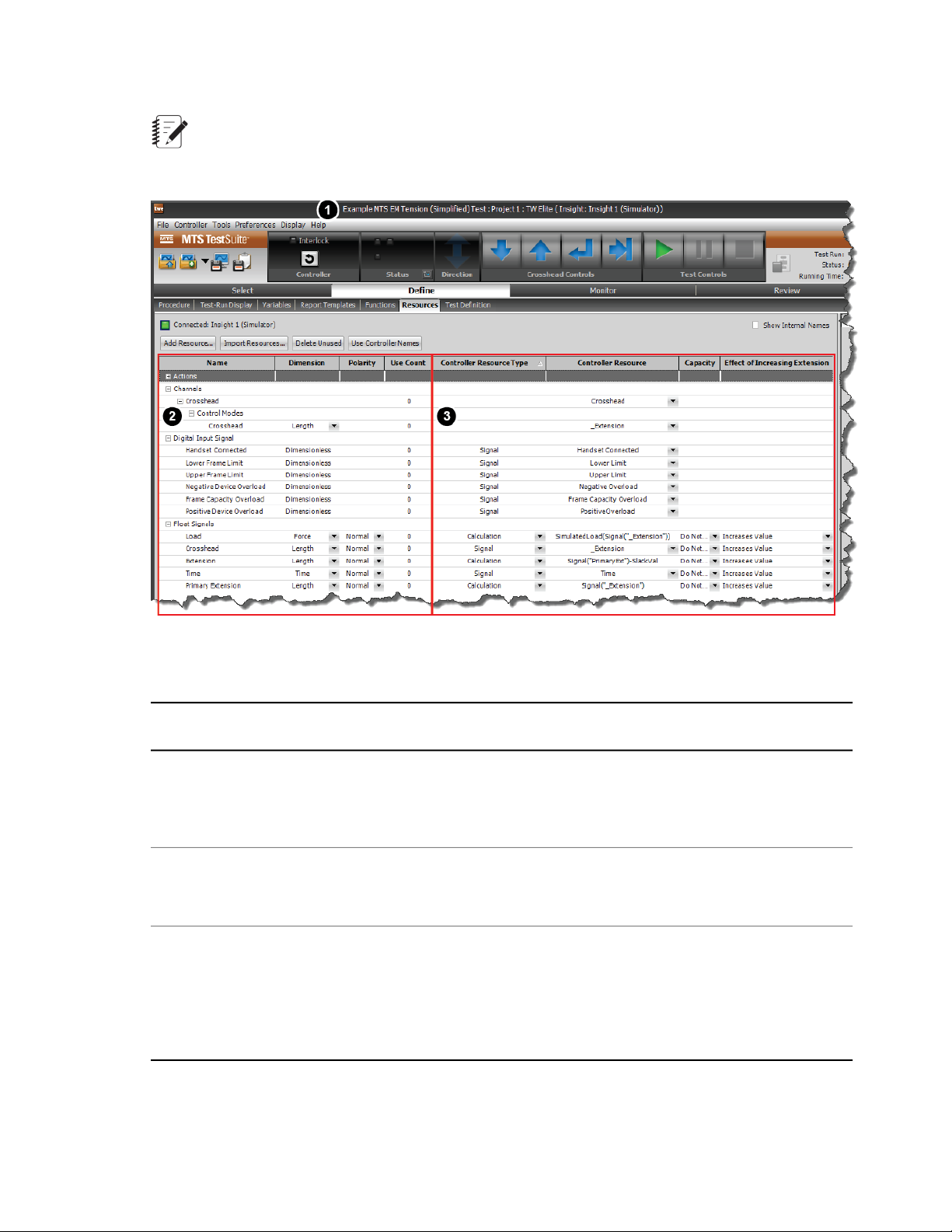
Working with MTS FlexTest Resources
Note:
When you create tests while the TWE application is connected to a controller, it is referred to as
“online” test design. You can also perform “offline” test design (see Offline Test Design (p. 102).)
1
3
For More Information
Offline Test Design (p. 102)
Controller and
station
identification
Test resources2
Controller
resources
Resources Tab
Description of Resources Tab
DescriptionItemNumber
When TWE is connected to a controller, the window title shows the
controller and station configuration associated with the current test. In
this example, the controller name is “MTS FlexTest 40”, and the station
configuration name is “2 chan.cfg”.
The resources in the Name column are test resources. Test resources
are required by the test and must map to equivalent resources in the
Controller Resources column when connected to a controller
The resources in this column are controller resources. Controller
resources represent resources in the physical station. Resource mapping
is saved with tests. When connected to a station, controller resources
reflect the resources in the Station Configuration file. When not connected
to a station, controller resources reflect the resources the TWE expects
to find when connected to a station.
MTS TestSuite | 97
Page 98

Working with MTS FlexTest Resources
Creating a Desktop Shortcut That Includes a Controller
Quick access:
Tools menu > Create Desktop Shortcut
Note:
This procedure only applies to MTS FlexTest controllers.
There are two types of desktop icons. One opens just the MTS TestSuite application, and the other will
open the controller and then open the MTS TestSuite application. The desktop shortcut that includes
opening the controller includes the configuration file name in its name, for example, “Multipurpose Express
(Station_Configuration.cfg).” If you have multiple stations, you can create a shortcut for each configuration
file.
To create the desktop shortcut that includes opening the controller:
1. Open your MTS TestSuite application: From the Start menu, select All Programs > MTS TestSuite
> application name.
2. From the Tools menu, click Create Desktop Shortcut. The Create Desktop Shortcut window opens.
3. Browse to the Station Configuration file you will be using, or type the file name in the Station Configuration
box. Ensure that this configuration file contains the parameter and tuning sets that you want the operator
to use for the tests.
4. If the Controller Name box is not already populated, type the name of the controller you will be using.
5. Click OK. The configuration message that states that the shortcut was created on the desktop appears.
Click OK.
6. To avoid confusion, delete other MTS TestSuite application desktop shortcuts.
Station Configurations
A station configuration is a discrete file that lists all or a portion of the resources in your physical station
(including resources not associated with hardware, such as control channels, control modes, and actions).
You create and modify station configurations with the MTS Series 793 Controller software. MTS typically
provides a station configuration when you receive your system.
When you connect to an MTS FlexTest controller with TWE, the controller resources shown on the
Resources tab are the same as the resources in the station configuration file.
98 | MTS TestSuite
Page 99

Working with MTS FlexTest Resources
Station Configuration File and Station Resources
Controller Resources
A station configuration may include only a portion of the resources available to the controller. The complete
inventory of resources available to your controller is defined by the hardware interface file (or .hwi file)
installed with your controller software. The .hwi file defines what internal components are available to your
controller, which controller slots they are installed in, and the rear-panel connectors through which they
are accessed.
When you connect to a station with TWE, the controller resources shown on the Resources tab pertain
only to the connected controller, and may not include all the resources in the hardware interface file.
Hardware Interface File and System Resources.
Note:
You use the Station Builder application (one of the applications included with MTS Series 793
Controller software) to define station configuration files by allocating some or all of the resources
listed in the .hwi file.
Resource Mapping
When you modify a test while the TWE application is connected to a controller and save it, the application
saves the resource map (how test resources align to controller resources) with the test definition. The
MTS TestSuite | 99
Page 100

Working with MTS FlexTest Resources
resource map saved in the test definition is an inventory of resources the TWE application expects to find
the next time it connects to a station.
You must either automatically or manually map the test resources to controller resources before you can
load and run the test procedure on that station. Resources are stored with the test definition and validated
against the available controller resources the next time the application connects to a station.
Automatic mapping example
Suppose you modify a test while TWE is connected to a controller. As part of your test, you add a Go To
activity and select a control channel named “Ch 1” and a control mode named “Displacement”. When you
do this, you are using the test resources that TWE mapped to the controller when TWE connected to the
controller. When you save the test, the names for all of the test resources in the test definition appear
identical to the equivalent controller resources on the Resources tab.
If you disconnect the controller from your test, TWE expects to find the same controller resources for the
current test in whatever controller you connect to in the future.
If you reconnect to the same controller, TWE maps the channel and control mode test resources to the
equivalent resources in the controller, and you can run the test immediately.
If you reconnect to a different controller, one of two things may occur:
• If TWE finds a control channel named “Ch 1” and a control mode named “Displacement” in the controller
with equivalent functionality, then TWE automatically maps them to the test resources with the same
name. If the remainder of the test resources also map to the controller resources in the new station,
you can run the test immediately.
• If TWE does not find a control channel named “Ch 1” and a control mode named “Displacement” in the
controller, it shows validation error icons. You must resolve these errors (and any other validation errors)
before you can run the test.
Manual mapping example
Suppose you modify a test while TWE is connected to a controller, and that the controller has a channel
named “Axial” with a control mode named “Length”. Now, suppose you disconnect from the station and
connect to a different controller that has a channel named “Ch 1” and a control mode named “Displacement”.
In this case, TWE is unable to automatically map the new controller resources to the test resources, and
shows error icons (1). To resolve the errors, you must manually map the controller resources to the test.
You do this by choosing compatible controller resources from the drop-down lists to resolve the mapping
errors, as shown in (2). In this example, the controller channel and control mode resource names “Ch 1”
and “Force”, have been mapped to the test channel and control mode names “Axial” and “Length”.
100 | MTS TestSuite
 Loading...