

MSI MS-6528LE, 845 Pro2, 845 Pro2-A, 845 Pro2-R, MS-6528 User Manual
i
Version 2.0
G52-MA00466
MS-6528 (v2.X) ATX Mainboard
MSI
MICRO-STAR INTERNATIONAL
845 Pro2
845 Pro2-A
845 Pro2-R
ii
Manual Rev: 2.0
Release Date: Oct. 2001
FCC-B Radio Frequency Interference Statement
This equipment has been tested and found to comply with the limits for a class
B digital device, pursuant to part 15 of the FCC rules. These limits are designed
to provide reasonable protection against harmful interference when the equipment is operated in a commercial environment. This equipment generates, uses
and can radiate radio frequency energy and, if not installed and used in accordance with the instruction manual, may cause harmful interference to radio
communications. Operation of this equipment in a residential area is likely to
cause harmful interference, in which case the user will be required to correct
the interference at his own expense.
Notice 1
The changes or modifications not expressly approved by the party responsible for compliance could void the user’s authority to operate the equipment.
Notice 2
Shielded interface cables and A.C. power cord, if any, must be used in order to
comply with the emission limits.
VOIR LA NOTICE D’INSTALLATION AVANT DE RACCORDER AU
RESEAU.
Micro-Star International MS-6528
Tested to comply
with FCC Standard
For Home or Office Use

iii
Edition
Oct. 2001
Copyright Notice
The material in this document is the intellectual property of MICROSTAR INTERNATIONAL. We take every care in the preparation
of this document, but no guarantee is given as to the correctness of its
contents. Our products are under continual improvement and we reserve the right to make changes without notice.
Trademarks
All trademarks used in this manual are the property of their respective
owners.
Intel and Pentium are registered trademarks of Intel Corporation.
PS/2 and OS/2 are registered trademarks of IBM Corporation.
Windows 95/98/2000 and Windows NT are registered trademarks of Microsoft.
Netware is a registered trademark of Novell.
Award is a registered trademark of Award Software Inc.
Revision History
Revision Revision History Date
V2.0 First release for PCB 2.X Oct. 2001

iv
1. Always read the safety instructions carefully.
2. Keep this User’s Manual for future reference.
3. Keep this equipment away from humidity.
4. Lay this equipment on a reliable flat surface before setting it up.
5. The openings on the enclosure are for air convection hence protects the
equipment from overheating. DO NOT COVER THE OPENINGS.
6. Make sure the voltage of the power source and adjust properly 110/220V
before connecting the equipment to the power inlet.
7. Place the power cord such a way that people can not step on it. Do not
place anything over the power cord.
8. Always Unplug the Power Cord before inserting any add-on card or module.
9. All cautions and warnings on the equipment should be noted.
10. Never pour any liquid into the opening that could damage or cause electrical shock.
11. If any of the following situations arises, get the equipment checked by a
service personnel:
z The power cord or plug is damaged
z Liquid has penetrated into the equipment
z The equipment has been exposed to moisture
z The equipment has not work well or you can not get it work according
to User’s Manual.
z The equipment has dropped and damaged
z If the equipment has obvious sign of breakage
12. DO NOT LEAVE THIS EQUIPMENT IN AN ENVIRONMENT
UNCONDITIONED, STORAGE TEMPERATURE ABOVE 600 C (1400F), IT
MAY DAMAGE THE EQUIPMENT.
Safety Instructions
CAUTION: Danger of explosion if battery is incorrectly replaced.
Replace only with the same or equivalent type recommended by the
manufacturer.

v
CONTENTS
Chapter 1. Getting Started ........................................................................ 1-1
Mainboard Specification ...................................................................... 1-2
Mainboard Layout ............................................................................... 1-4
Quick Components Guide .................................................................... 1-7
Key Features ........................................................................................ 1-8
MSI Special Features ........................................................................... 1-9
Fuzzy Logic™ III ........................................................................... 1-9
PC Alert™ III ............................................................................... 1-10
D-Bracket™ & D-LED™ (Optional) ............................................. 1-12
Live BIOS™/Live Driver™ .......................................................... 1-14
Chapter 2. Hardware Setup ....................................................................... 2-1
Central Processing Unit: CPU .............................................................. 2-2
CPU Installation Procedures ......................................................... 2-2
Installing the CPU Fan .................................................................. 2-3
CPU Core Speed Derivation Procedure ......................................... 2-4
Memory ................................................................................................2-5
Introduction to SDR SDRAM ....................................................... 2-5
SDR Module Combination ............................................................ 2-6
Installing SDR Modules ................................................................ 2-6
Power Supply ....................................................................................... 2-7
ATX 20-Pin Power Connector: JWR1 ............................................ 2-7
ATX 12V Power Connector: JPW1 ................................................ 2-7
Back Panel ............................................................................................ 2-8
Mouse Connector: JKBMS1 ......................................................... 2-8
Keyboard Connector: JKBMS1 ..................................................... 2-9
USB Connectors ............................................................................ 2-9
Serial Port Connector: COM A & COM B ................................... 2-10
Joystick/Midi Connectors ........................................................... 2-10
Audio Port Connectors ............................................................... 2-10

vi
Parallel Port Connector: LPT1 ...................................................... 2-11
Connectors ......................................................................................... 2-12
Floppy Disk Drive Connector: FDD1 ........................................... 2-12
Chassis Intrusion Switch Connector: J4 ...................................... 2-12
Hard Disk Connectors: IDE1 & IDE2 ........................................... 2-13
Ultra ATA/133 Connectors: IDE3 & IDE4 (for 845 Pro2-A only) . 2-14
IDE RAID Connectors: IDE3 & IDE4 (for 845 Pro2-R only) ......... 2-14
CD-In Connector: JCD1 ............................................................... 2-15
Aux Line-In Connector: JAUX1 .................................................. 2-15
Modem-In Connector: JPHN1 ..................................................... 2-15
Fan Power Connectors: CFAN1/SFAN1/PSFAN1 ....................... 2-16
Wake On Ring Connector: JMDM1 ............................................. 2-17
Wake On LAN Connector: JWOL1 .............................................. 2-17
Power Saving LED Connector: JGL1 ........................................... 2-18
TOP TECH. III: J2 ........................................................................ 2-19
Power Saving Switch Connector: JGS1 ........................................ 2-19
Front Panel Connector: JFP1 or F_P2 (optional Intel spec) ......... 2-20
Front Panel Audio Connector: JAUD1 ........................................ 2-21
Front USB Connectors: JUSB1 or JUSB2 (optional Intel spec) ... 2-22
IrDA Infrared Module Header: IR1 or IR2 (optional Intel spec) .. 2-23
D-Bracket™ Connector: J8 .......................................................... 2-24
Jumpers .............................................................................................. 2-25
Clear CMOS Jumper: JBAT1 ........................................................ 2-25
BIOS Flash Jumper: J6 ................................................................. 2-26
Slots ................................................................................................... 2-27
AGP (Accelerated Graphics Port) Slot ......................................... 2-27
PCI Slots ...................................................................................... 2-27
CNR (Communication Network Riser) ......................................... 2-28
PCI Interrupt Request Routing .................................................... 2-28

vii
Chapter 3. BIOS Setup .............................................................................. 3-1
Control Keys ................................................................................. 3-2
Entering Setup ...................................................................................... 3-2
Getting Help .................................................................................. 3-3
The Main Menu ................................................................................... 3-4
Standard CMOS Features .................................................................... 3-6
Advanced BIOS Features .................................................................... 3-8
Advanced Chipset Features ............................................................... 3-12
Integrated Peripherals ........................................................................ 3-14
Power Management Setup ................................................................. 3-18
PNP/PCI Configurations ..................................................................... 3-22
PC Health Status ................................................................................ 3-24
Frequency/Voltage Control ................................................................ 3-25
Load High Performance/BIOS Setup Defaults .................................... 3-27
Supervisor/User Password ................................................................. 3-29
Appendix A: Using 4-/6-channel Audio Function ..................................... A-1
Installing C-Media Drivers .................................................................. A-2
Hardware Configuration ...................................................................... A-2
Software Configuration ....................................................................... A-3
Appendix B: MSI Smart Key ..................................................................... B-1
Installing MSI Smart Key .................................................................... B-2
Using MSI Smart Key ......................................................................... B-3
Glossary .................................................................................................... G-1

Getting Started
1-1
Chapter 1. Getting Started
TOPICS
Mainboard Specification 1-2
Mainboard Layout 1-4
Quick Components Guide 1-7
Key Features 1-8
MSI Special Features 1-9
1
Getting Started
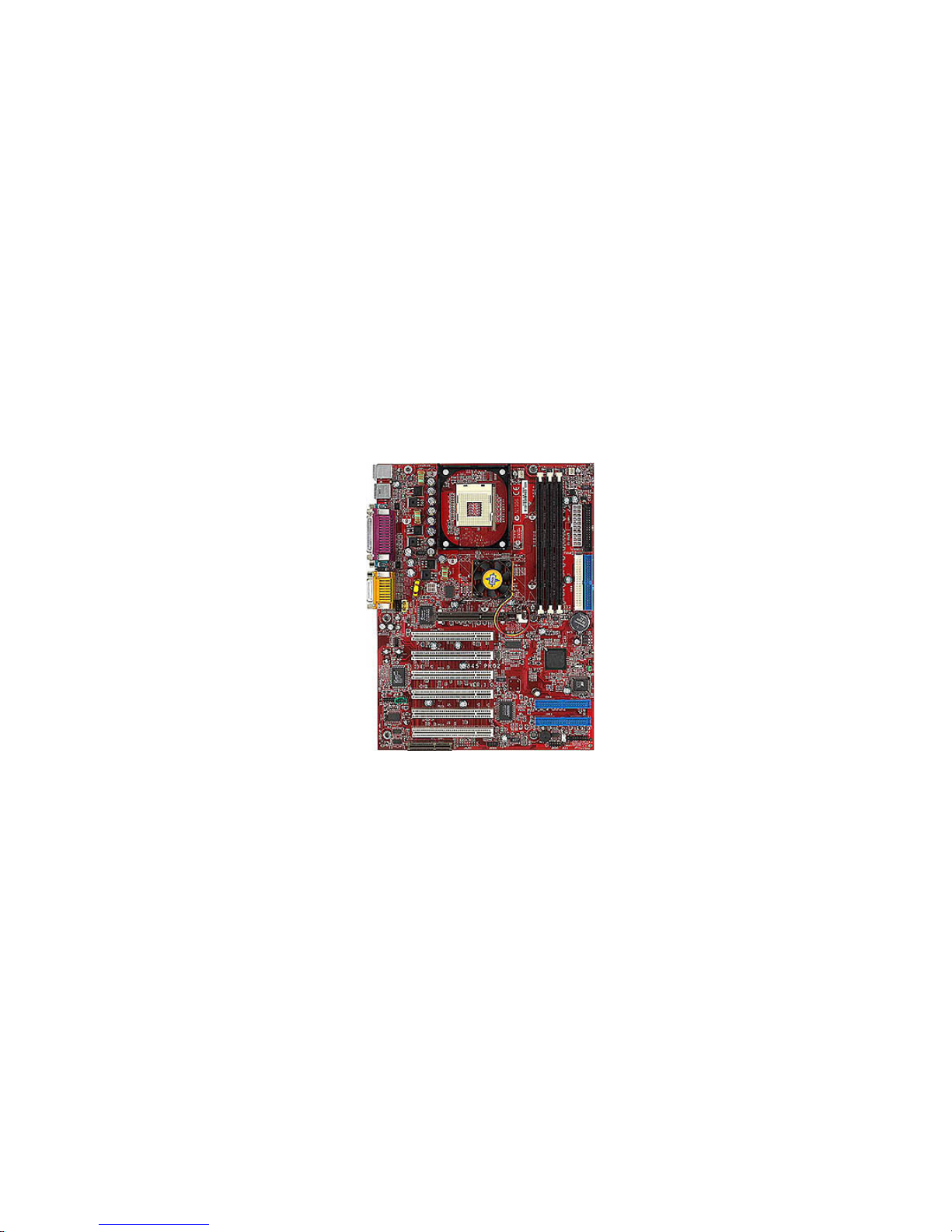
Thank you for purchasing the MS-6528 v2.X ATX mainboard. The MS6528 v2.X series include 845 Pro2, 845 Pro2-A, and 845 Pro2-R mainboards. The
845 Pro2 is a standard version. In addition to standard features, the 845 Pro2-A
offers Ultra ATA/133 interface and the 845 Pro2-R supports IDE RAID 0, 1
technology. All three models are based on Intel® 82845 & 82801BA chipsets
for optimal system efficiency. Designed to fit the advanced Intel® Pentium® 4
processors in the 478 pin package, the MS-6528 v2.X delivers a high performance and professional desktop platform solution.

Chapter 1
1-2
CPU
Supports Intel® Pentium® 4 processor in 478 pin package.
Supports 1.5GHz, 1.6GHz, 1.7GHz, 1.8GHz, 1.9GH z, 2GHz and up.
Chipset
Intel® 845 chipset (593 FC-BGA)
- Supports SDRAM at 133MHz operation (PC133).
- AGTL+ host bus with integrated termination supporting 32-bit host
addressing.
- 1.5V AGP interface with 4x data transfer and 4x fast write capability.
- 8-bit, 66MHz 4x hub interface to the Intel ICH2.
Intel® ICH2 chipset (360 EBGA)
- Upstream hub interface for access to the Intel MCH.
- 2-channel Ultra ATA/100 Bus Master IDE controller.
- USB controller 1.1 (expanded capabilities for 4 ports).
- I/O APIC.
- SMBus controller.
- FWH interface.
- LPC interface.
- AC’97 2.1 interface.
- PCI 2.2 interface.
- Integrated system management controller.
Main Memory
Supports three PC133 SDRAM slots.
Supports up to 3GB memory size.
Slots
One AGP (Accelerated Graphics Port) 4x slot (1.5V only).
Six PCI 2.2 32-bit Master PCI bus slots (support 3.3V/5V PCI bus interface).
One CNR (Communication Network Riser) slot.
Mainboard Specification
Note: The AGP slot DOES NOT support 3.3V AGP card. Use of
3.3V AGP card may cause damage to the mainboard.

Getting Started
1-3
On-Board IDE
An IDE controller on the ICH2 chipset provides IDE HDD/CD-ROM with
PIO, Bus Master and Ultra DMA33/66/100 operation modes.
Can connect up to four IDE devices.
Ultra ATA/133 supported by Promise PDC20275 (for 845 Pro2-A only).
IDE RAID 0, 1 supported by Promise PDC20265R (for 845 Pro2-R only).
On-Board Peripherals
On-Board Peripherals include:
- 1 floppy port supports 2 FDDs with 360K, 720K, 1.2M, 1.44M and
2.88Mbytes.
- 2 serial ports (COM A + COM B).
- 1 parallel port supports SPP/EPP/ECP mode.
- 4 USB ports (Rear * 2/ Front * 2)
- 1 IrDA connector for SIR/ASKIR/HPSIR.
- 1 D-Bracket™ pin header.
- 1 audio/game port.
Audio
C-Media CMI8738 / PCI-6ch supports 2/4/6 ch speaker.
BIOS
The mainboard BIOS provides “Plug & Play” BIOS which detects the peripheral devices and expansion cards of the board automatically.
The mainboard provides a Desktop Management Interface (DMI) function
which records your mainboard specifications.
Dimension
ATX Form Factor 30.5cm x 23cm.
Mounting
6 mounting holes.
Chapter 1
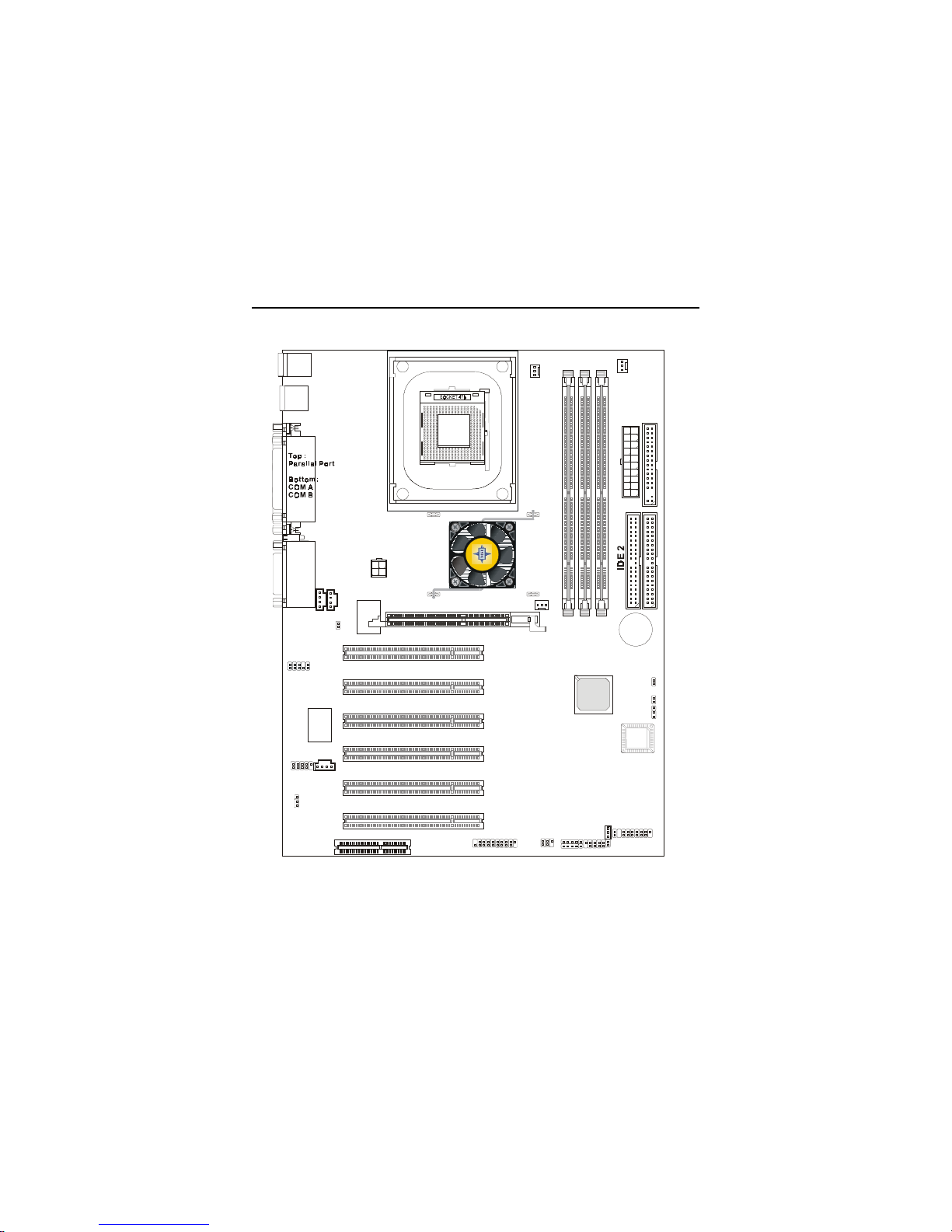
1-4
J8
SFAN1
PSFAN1
CFAN1
JGL1
J2
BATT
+
ICH 2
D
I
M
M
1
D
I
M
M
2
D
I
M
M
3
A
T
X
P
o
w
e
r
S
u
p
p
l
y
FWH
PCI Slot 5
PCI Slot 4
PCI Slot 3
PCI Slot 2
PCI Slot 1
I
D
E
1
W
i
n
b
o
n
d
W
8
3
6
2
7
H
F
USB
ports
Top : mo use
Bottom: keyboard
J
C
D
1
C
M
I
8
7
3
8
JPW1
J6
J4
JBAT1
J
A
U
X
1
JPHN1
Top :
Game port
Bottom:
Line-Out
Line-In
Mic
F
D
D
1
I
n
t
e
l
8
4
5
c
h
i
p
s
e
t
AGP Slot
JAUD1
JFP1
JWOL1
JGS1
JMDM1
F_P2
(optional)
IR1
IR2
PCI Slot 6
CNR
JUSB1
JUSB2
(optional)
D-LED
(optional)
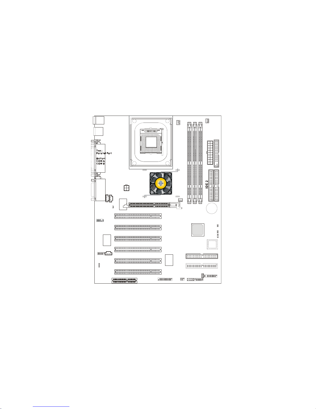
Mainboard Layout
845 Pro2 (MS-6528 v2.X) ATX Mainboard
Getting Started
1-5
J8
SFAN1
PSFAN1
CFAN1
JGL1
J2
BATT
+
ICH 2
D
I
M
M
1
D
I
M
M
2
D
I
M
M
3
A
T
X
P
o
w
e
r
S
u
p
p
l
y
FWH
PCI Slot 5
PCI Slot 4
PCI Slot 3
PCI Slot 2
PCI Slot 1
I
D
E
1
IDE 4
IDE 3
W
i
n
b
o
n
d
W
8
3
6
2
7
H
F
P
R
O
M
I
S
E
P
D
C
2
0
2
7
5
USB
ports
Top : mo use
Bottom: keyboard
J
C
D
1
C
M
I
8
7
3
8
JPW1
J6
J4
JBAT1
J
A
U
X
1
JPHN1
Top :
Game port
Bottom:
Line-Out
Line-In
Mic
F
D
D
1
I
n
t
e
l
8
4
5
c
h
i
p
s
e
t
AGP Slot
JAUD1
JFP1
JWOL1
JGS1
JMDM1
F_P2
(optional)
IR1
IR2
PCI Slot 6
CNR
JUSB1
JUSB2
(optional)
D-LED
(optional)
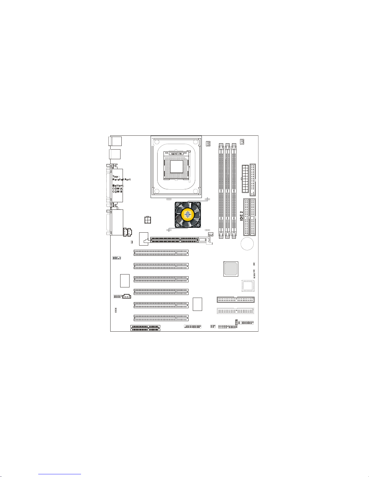
845 Pro2-A (MS-6528 v2.X) ATX Mainboard
Chapter 1
1-6
J8
SFAN1
PSFAN1
CFAN1
JGL1
J2
BATT
+
ICH 2
D
I
M
M
1
D
I
M
M
2
D
I
M
M
3
A
T
X
P
o
w
e
r
S
u
p
p
l
y
FWH
PCI Slot 5
PCI Slot 4
PCI Slot 3
PCI Slot 2
PCI Slot 1
I
D
E
1
IDE 4
IDE 3
W
i
n
b
o
n
d
W
8
3
6
2
7
H
F
P
R
O
M
I
S
E
P
D
C
2
0
2
6
5
R
USB
ports
Top : mo use
Bottom: keyboard
J
C
D
1
C
M
I
8
7
3
8
JPW1
J6
J4
JBAT1
J
A
U
X
1
JPHN1
Top :
Game port
Bottom:
Line-Out
Line-In
Mic
F
D
D
1
I
n
t
e
l
8
4
5
c
h
i
p
s
e
t
AGP Slot
JAUD1
JFP1
JWOL1
JGS1
JMDM1
F_P2
(optional)
IR1
IR2
PCI Slot 6
CNR
JUSB1
JUSB2
(optional)
D-LED
(optional)
845 Pro2-R (MS-6528 v2.X) ATX Mainboard

Getting Started
1-7
Quick Components Guide
Component Function Reference
JWR1 ATX 20-pin power connector See p. 2-7
JPW1 ATX 12V power connector See p. 2-7
JKBMS1 Mouse connector See p. 2-8
JKBMS1 Keyboard connector See p. 2-9
USB Connectors Connecting to USB devices See p. 2-9
COM A & COM B Serial port connector See p. 2-10
LPT1 Parallel port connector See p. 2-11
FDD1 Floppy disk drive connector See p. 2-12
J4 Chassis intrusion switch See p. 2-12
IDE1~ IDE2 Hard disk connectors See p. 2-13
IDE3~IDE4 IDE RAID/ATA133 connectors See p. 2-14
JCD1 CD-in connector See p. 2-15
JAUX1 Aux line-in connector See p. 2-15
JPHN1 Modem-in connector See p. 2-15
CFAN1/SFAN1/PSFAN1 Fan power connectors See p. 2-16
JMDM1 Wake on ring connector See p. 2-17
JWOL1 Wake on LAN connector See p. 2-17
JGL1 Power saving LED connector See p. 2-18
J2 TOP TECH. III See p. 2-19
JGS1 Power saving switch connector See p. 2-19
JFP1/F_P2 Front panel connector See p. 2-20
JAUD1 Front panel audio connector See p. 2-21
JUSB1/JUSB2 Front USB connector See p. 2-22
IR1/IR2 IrDA infrared module connector See p. 2-23
J8 D-Bracket connector See p. 2-24
JBAT1 Clear CMOS jumper See p. 2-25
J6 BIOS flash jumper See p. 2-26
AGP Slot Connecting to AGP cards See p. 2-27
PCI Slots Connecting to expansion cards See p. 2-27
CNR Slot Connecting to expansion cards See p. 2-28

Chapter 1
1-8
ATX Form Factor
CPU: Intel® Pentium® 4 processor in the 478 pin package
Ultra ATA/133 supported by Promise PDC20275 (for 845 Pro2-A only)
IDE RAID 0, 1 supported by Promise PDC20265R (for 845 Pro2-R only)
C-Media CMI8738/PCI-6ch supports 2/4/6 channel speaker
Fuzzy Logic™ III
Live BIOS™ / Live Driver™
Smart Key™ - the best solution to prevent unauthorized access to your PC
PC Alert™ III system hardware monitor
D-Bracket™/D-LED™ (optional)
LAN Wake Up Function
Modem (Internal/External) Ring Wake Up Function
Suspend to RAM/Disk
PC2001 Compliant
Key Features
Getting Started
1-9
MSI Special Features
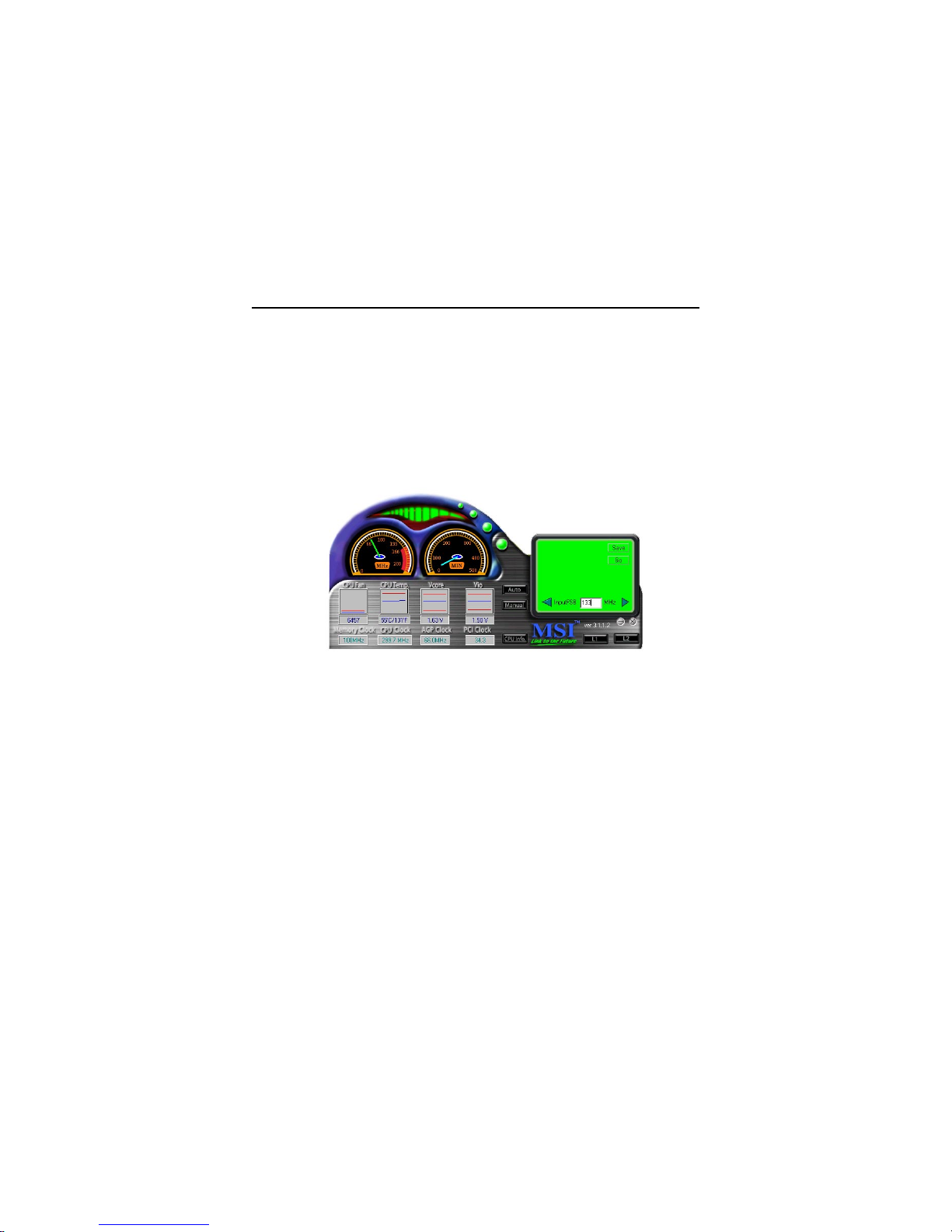
Fuzzy Logic™ III
The Fuzzy Logic™ III utility allows users to overclock the CPU FSB
(Front Side Bus) frequency in the Windows environment. Select the CPU frequency you prefer and click Go to apply the frequency or click Save allowing
the system to run at the specified frequency each time when the system is
powered on.
Features:
z Display Current System Status
- CPU Fan
- CPU Temp.
- Vcore
- Vio
- Memory Clock
- CPU Clock
- AGP Clock
- PCI Clock
z Adjust CPU FSB Frequency
Chapter 1
1-10
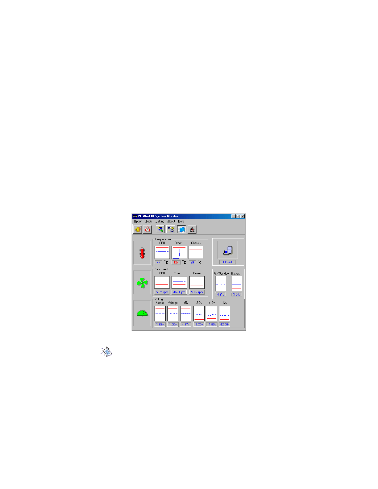
PC Alert™ III
The PC AlertTM III is a utility you can find in the CD-ROM disk. The
utility is just like your PC doctor that can detect the following PC hardware
status during real time operation:
* monitor CPU & system temperatures
* monitor fan speed(s)
* monitor system voltage
* monitor chassis intrusion
If one of the items above is abnormal, the program main screen will be
immediately shown on the screen, with the abnormal item highlighted in red.
This will continue to be shown,until user disables the warning.
Note: Items shown on PC Alert III vary depending on your system’s
status.

Getting Started
1-11
Features:
z Network Management
- Monitoring & remote control
z Basic System Utilities
- Scandisk & Defragment to maintain your HDD
z 3D Graphics Design
- Enables a more friendly user interface
z Sofware Utilities
- SoftCooler Optimized Cooling
Chapter 1
1-12
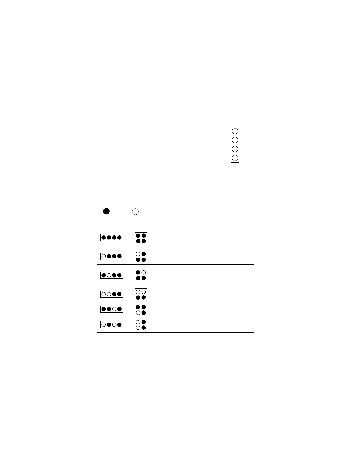
D-Bracket™ & D-LED™ (Optional)
The D-LED™ uses graphic signal display to help users understand their system. Four LEDs embedded in the
mainboard provide up to 16 combinations of signals to debug the system. The 4 LEDs can debug all problems that
fail the system, such as VGA, RAM or other failures. This
special feature is very useful for the overclocking users.
These users can use the feature to detect if there are any
problems or failures.
The D-Bracket™ which integrates four Diagnostic LEDs is optional.
Definitions of the D-Bracket™ LED signals are the same as D-LED™ as shown
below.
Red
Green
D-LED D-Bracket Description
System Power ON
- The D-LED will hang here if the processor is damaged or
not installed properly.
Early Chipset Initialization
Memory Detection Test
- Testing onboard memory size. The D-LED will hang if
the memory module is damaged or not installed properly.
Decompressing BIOS image to RAM for fast booting.
Initializing Keyboard Controller.
Testing VGA BIOS
- This will start writing VGA sign-on message to the screen.
1 2 3 4
1 2
3 4
1
2
3
4
Diagnostic LED
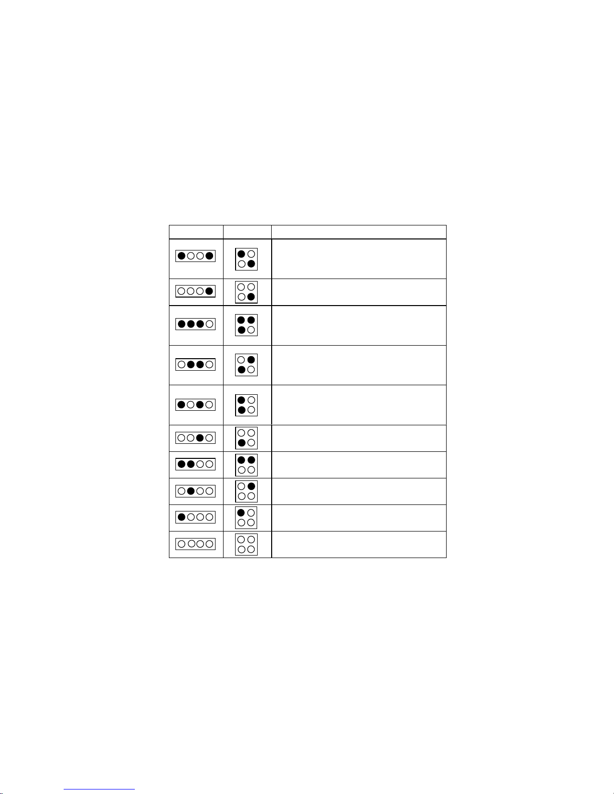
Getting Started
1-13
D-LED D-Bracket Description
Processor Initialization
- This will show information regarding the processor (like
brand name, system bus, etc…)
Testing RTC (Real Time Clock)
Initializing Video Interface
- This will start detecting CPU clock, checking type of video
onboard. Then, detect and initialize the video adapter.
BIOS Sign On
- This will start showing information about logo, processor
brand name, etc….
Testing Base and Extended Memory
- Testing base memory from 240K to 640K and extended
memory above 1MB u sing various patterns.
Assign Resources to all ISA.
Initializing Hard Drive Controller
- This will initialize IDE drive and controller.
Initializing Floppy Drive Controller
- This will initializing Floppy Drive and controller.
Boot Attempt
- This will set low stack and boot via INT 19h.
Operating System Booting
Chapter 1
1-14
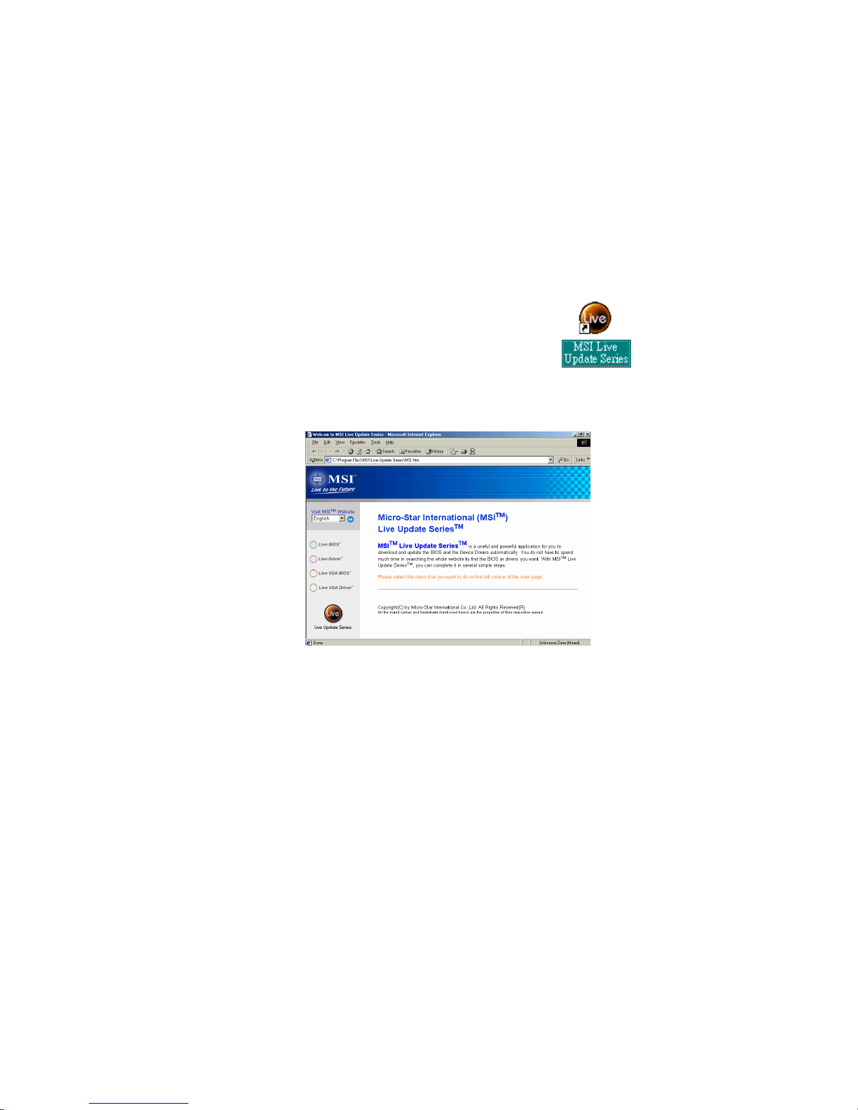
Live BIOS™/Live Driver™
The Live BIOSTM is a tool used to detect and update your
BIOS online so that you don’t need to search for the correct
BIOS version through the whole web site. To use the function,
you need to install the “MSI Live Update Series” application.
After installation, the “MSI Live Update Series” icon (as the
right view) will appear on the screen.
Double click the “MSI Live Update Series” icon, and the following screen
will appear.
Four buttons are placed on the left column of the screen. Click the desired
button to start the update process.
zz
zz
z Live BIOS – Updates the BIOS online. If your motherboard does not support
the function, the “sorry” message is displayed.
zz
zz
z Live Driver – Updates the drivers online. If your motherboard does not sup-
port the function, the “sorry” message is displayed.
zz
zz
z Live VGA BIOS – Updates the VGA BIOS online. If your VGA device does
not support the function, the “sorry” message appears.
zz
zz
z Live VGA Driver – Updates the VGA driver online. If your VGA device does
not support the function, the “sorry” message is displayed.
For more information on the update instructions, insert the companion CD and
refer to the “Live Update Series Guide” under the “Manual” tab.

Hardware Setup
2-1
Chapter 2. Hardware Setup
TOPICS
Central Processing Unit: CPU 2-2
Memory 2-5
Power Supply 2-7
Back Panel 2-8
Connectors 2-12
Jumpers 2-25
Slots 2-27
2
Hardware Setup
This chapter provides you with the information about hardware setup
procedures. While doing the installation, be careful in holding the components
and follow the installation procedures. For some components, if you install in
the wrong orientation, the components will not work properly.
Use a grounded wrist strap before handling computer components. Static
electricity may damage the components.
Chapter 2
2-2
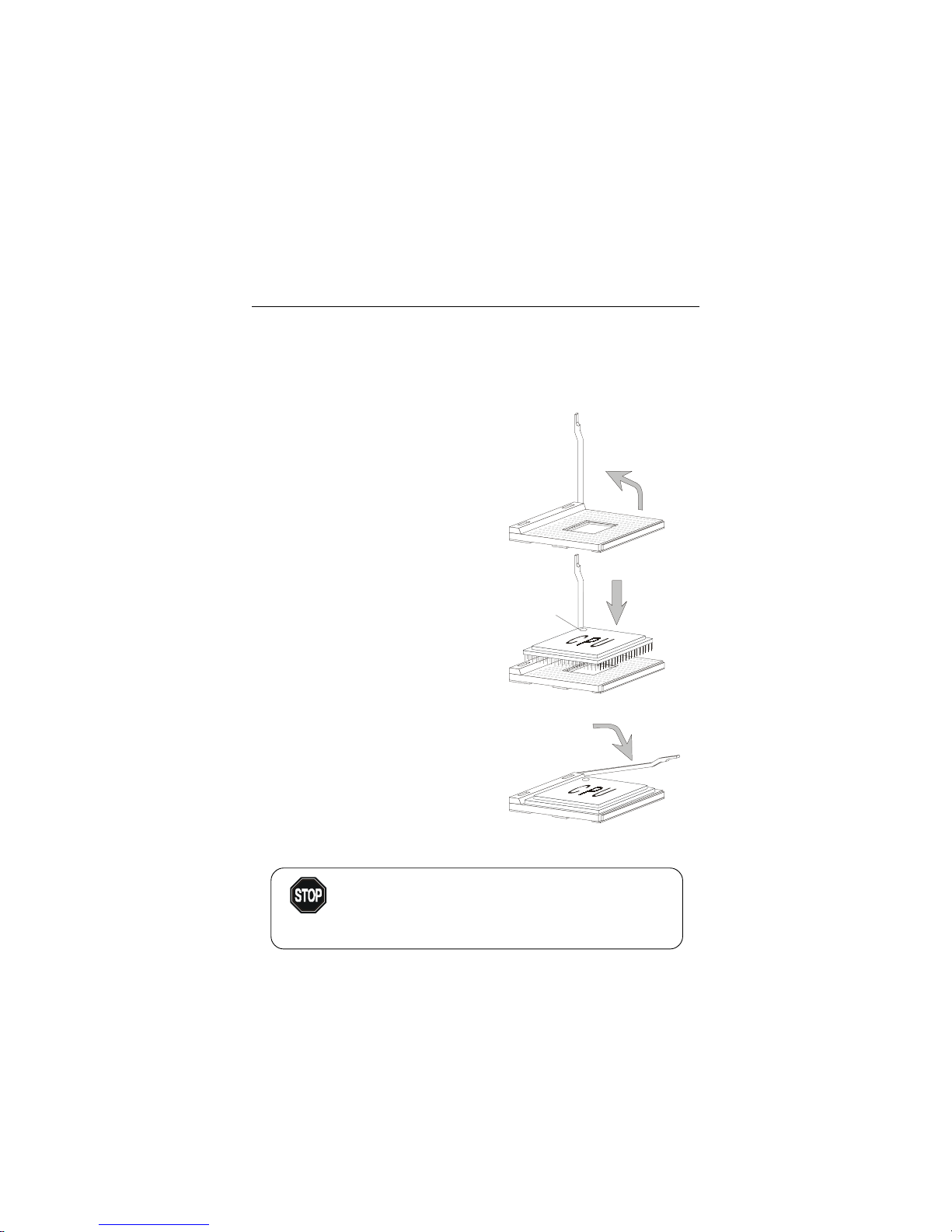
Central Processing Unit: CPU
1. Pull the lever sideways away
from the socket. Then, raise
the lever up to a 90-degree
angle.
2. Look for the dot/cut edge. The
dot/cut edge should point towards the lever pivot. The
CPU will only fit in the correct
orientation.
3. Hold the CPU down firmly,
and then close the lever to
complete the installation.
CPU Installation Procedures
Open Lever
Dot / Cut edge
Sliding
Plate
Close
Lever
The mainboard supports Intel® Pentium® 4 processor in the 478 pin
package. The mainboard uses a CPU socket called PGA478 for easy CPU
installation. When you are installing the CPU, make sure the CPU has a heat
sink and a cooling fan attached on the top to prevent overheating. If you do not
find the heat sink and cooling fan, contact your dealer to purchase and install
them before turning on the computer.
Overheating will seriously damage the CPU and system,
always make sure the cooling fan can work properly to
protect the CPU from overheating.
WARNING!
Hardware Setup
2-3
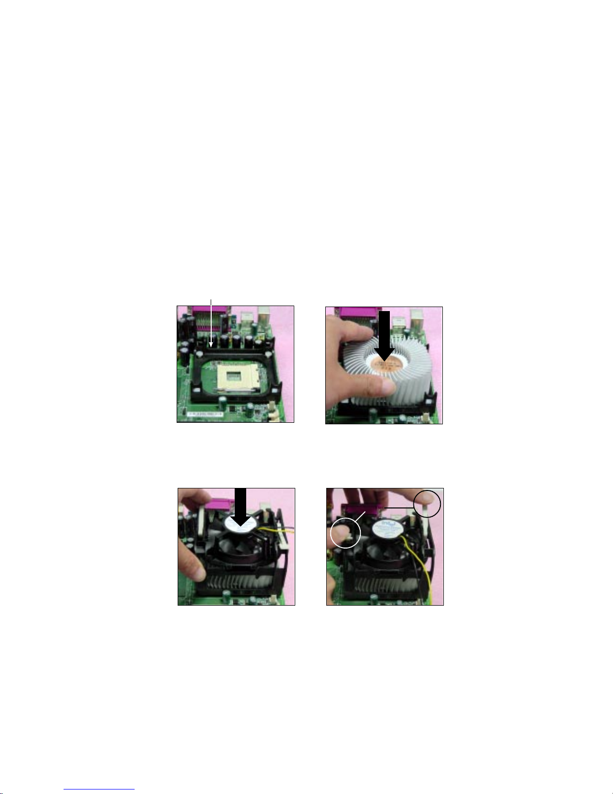
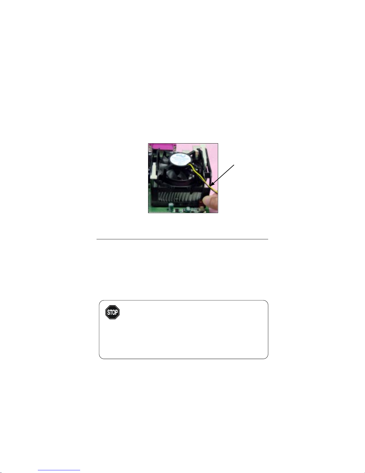
Installing the CPU Fan
As processor technology pushes to faster speeds and higher
performance, thermal management becomes increasingly important. To dissipate heat, you need to attach the CPU cooling fan and heatsink on top of the
CPU. Follow the instructions below to install the Heatsink/Fan:
2. Position the heatsink onto the reten-
tion mechanism.
1. Locate the CPU and its retention
mechanism on the motherboard.
3. Mount the fan on top of the heatsink.
Press down the fan until its four clips
get wedged in the holes of the retention mechanism.
4. Press the two levers down to fasten
the fan. Each lever can be pressed
down in only ONE direction.
retention mechanism
levers
Chapter 2
2-4
CPU Core Speed Derivation Procedure
If CPU Clock = 100MHz
Core/Bus ratio = 14
then CPU core speed = Host Clock x Core/Bus ratio
= 100MHz x 14
= 1.4GHz
5. Connect the fan power cable from the mounted fan to the 3-pin fan power connector
on the board.
fan power cable
Overclocking
This motherboard is designed to support overclocking.
However, please make sure your components are able to
tolerate such abnormal setting, while doing overclocking.
Any attempt to operate beyond product specifications is not
recommended. We do not guarantee the damages or risks
caused by inadequate operation or beyond product
specifications.
WARNING!
Hardware Setup
2-5
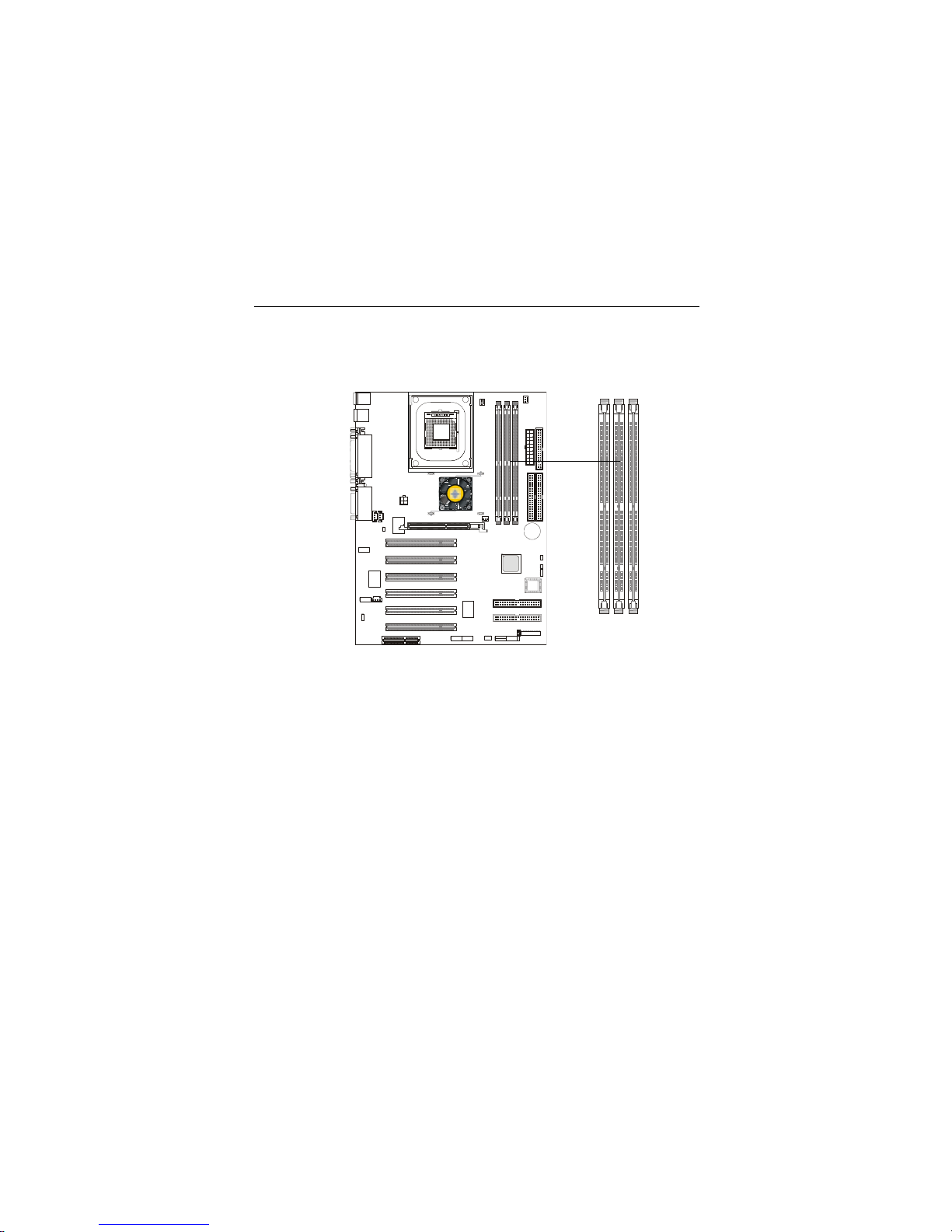
Memory
The mainboard supports a maximum memory size of 3GB. It provides
three 168-pin unbuffered SDRAM DIMM (Double In-Line Memory Module)
sockets and supports 64MB to 512MB technology.
Introduction to SDR SDRAM
Synchronous DRAM is a type of dynamic RAM memory chip that has
been widely used starting in the latter part of the 1990s. SDRAMs are based on
standard dynamic RAM chips, but have sophisticated features that make them
considerably faster. First, SDRAM chips are fast enough to be synchronized
with the CPU's clock, which eliminates wait states. Second, the SDRAM chip is
divided into two cell blocks, and data is interleaved between the two so that
while a bit in one block is being accessed, the bit in the other is being prepared
for access. This allows SDRAM to burst the second and subsequent, contiguous characters at a rate of 10ns, compared to 60ns for the first character.
SDRAM provides 800 MBps or 1 GBps data transfer depending on
whether the bus is 100MHz or 133MHz.
D
I
M
M
1
D
I
M
M
2
D
I
M
M
3
Chapter 2
2-6
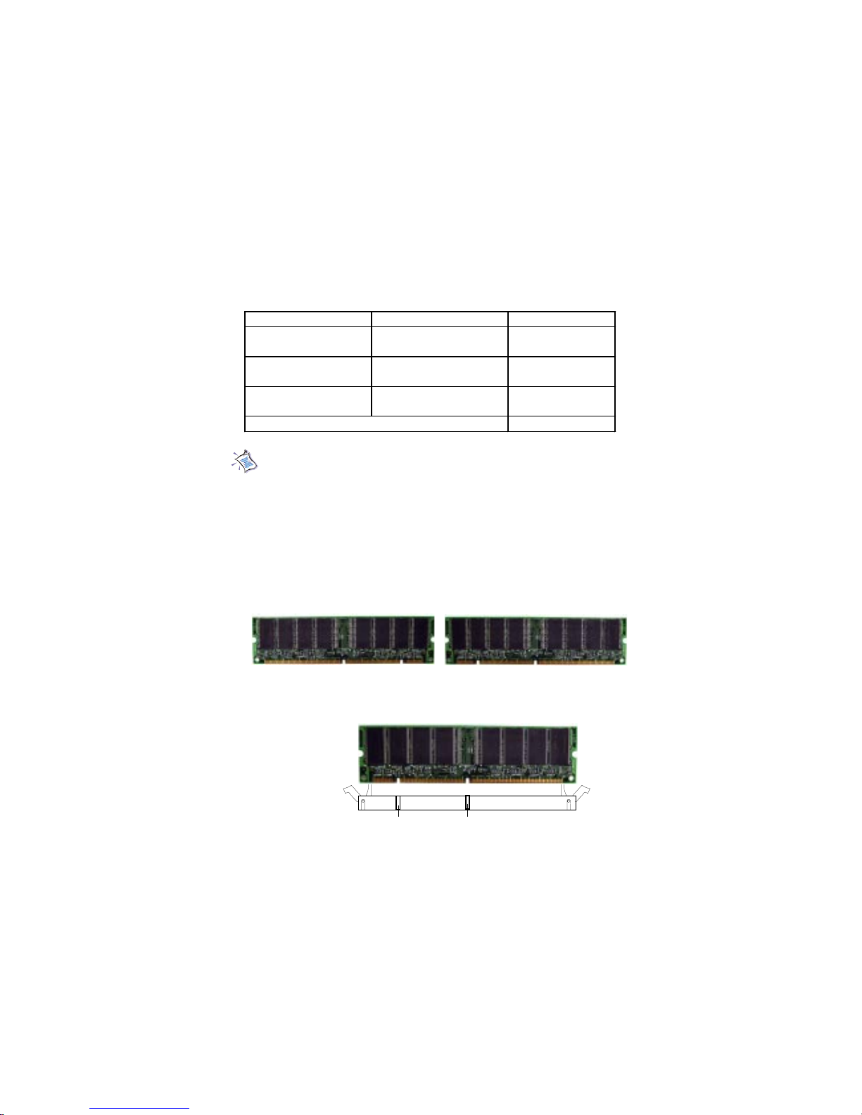
SDR Module Combination
Y ou can install memory modules in any combination as follows:
Socket M em ory M odule Total M em ory
Sock et 1
(Bank 0 & Bank 1)
64M B , 128M B ,
256M B , 512M B , 1G B
64M B~1GB
Sock et 2
(Bank 2 & Bank 3)
64M B , 128M B ,
256M B , 512M B , 1G B
64M B~1GB
Sock et 3
(Bank 4 & Bank 5)
64M B , 128M B ,
256M B , 512M B , 1G B
64M B~1GB
Total System M em ory
64M B~3GB
Note: As Intel® 845 chipset does not properly support the PC100
memory, it is strongly recommended that users install PC133 DIMM
modules for better system performance and stability. We do not guarantee the system stability when installing PC 100 DIMM modules.
1. The DIMM slot has 2 Notch Keys “VOLT and DRAM”, so the
DIMM memory module can only fit in one direction.
2. Insert the DIMM memory module vertically into the DIMM slot.
Then push it in.
3. The plastic clip at the side of the DIMM slot will automatically close.
VOLTDRAM
Front View Rear View
Installing SDR Modules
Hardware Setup
2-7
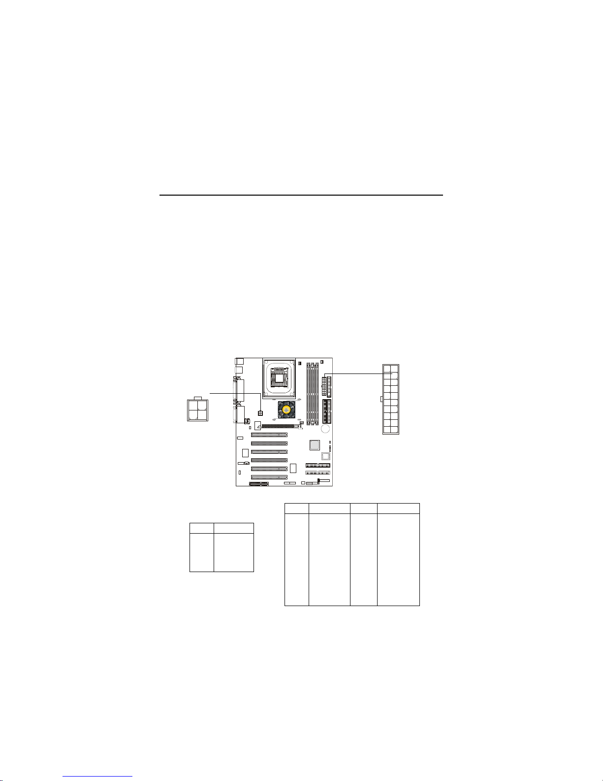
Power Supply
A TX 20-Pin Power Connector: JWR1
This connector allows you to connect to an ATX power supply. To
connect to the ATX power supply, make sure the plugs of the power supply is
inserted in the proper orientation and the pins are aligned. Then push down
the power supply firmly into the connector. The power connector supports
instant power on function which means that system will boot up immediately
when the power supply connector is inserted on the board.
The mainboard supports ATX power supply for the power system. Before inserting the power supply connector, always make sure that all components are installed properly to ensure that no damage will be caused.
A TX 12V Power Connector: JPW1
This 12V power connector is used to provide power to the CPU.
JPW1
1
3
2
4
JWR1
10
1
20
11
PIN SIGNAL
1 GND
2 GND
3 12V
4 12V
JPW1 Pin Definition
PIN SIGNAL
1 1 3.3V
12 -12V
13 GND
14 PS_ON
15 GND
16 GND
17 GND
18 -5V
19 5V
20 5V
PIN SIGNAL
1 3.3V
2 3.3V
3 GND
45V
5 GND
65V
7 GND
8 PW_OK
9 5V_SB
10 12V
JWR1 Pin Definition
Chapter 2
2-8
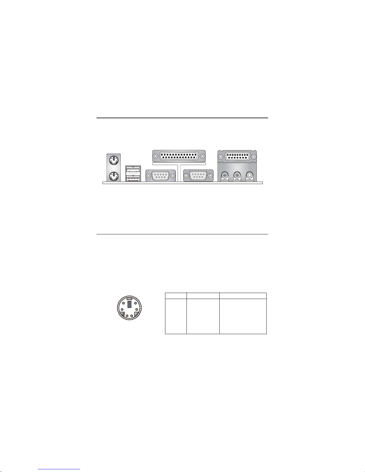
The Back Panel provides the following connectors:
Back Panel
Mouse Connector: JKBMS1
The mainboard provides a standard PS/2® mouse mini DIN connector for
attaching a PS/2® mouse. You can plug a PS/2® mouse directly into this
connector. The connector location and pin assignments are as follows:
PS/2 Mouse (6-pin Female)
Mouse
Keyboard USB
Parallel
COM A COM B L-out L-in MIC
Midi/Joystick
2
1
3
4
56
PIN SIGNAL DESCRIPTION
1 Mouse DATA Mouse DA TA
2 NC No connection
3 GND Ground
4 VCC +5V
5 Mouse Clock Mouse clock
6 NC No connection
Pin Definition
Hardware Setup
2-9
Keyboard Connector: JKBMS1
The mainboard provides a standard PS/2® keyboard mini DIN connector
for attaching a PS/2® keyboard. You can plug a PS/2® keyboard directly into
this connector.
PS/2 Keyboard (6-pin Female)
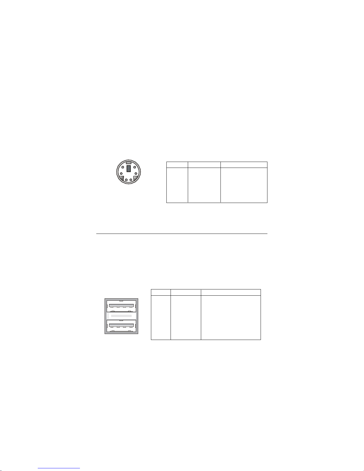
USB Connectors
The mainboard provides a UHCI (Universal Host Controller Interface)
Universal Serial Bus root for attaching USB devices such as keyboard, mouse
or other USB-compatible devices. You can plug the USB device directly into
ths connector.
USB Ports
1 2 3 4
5 6 7 8
PIN SIGNAL DESCRIPTION
1 VCC +5V
2 -Data 0 Negative Data Channel 0
3 +Data0 Positive Data Channel 0
4 GND Ground
5 VCC +5V
6 -Data 1 Negative Data Channel 1
7 +Data 1 Positive Data Channel 1
8 GND Ground
USB Port Description
2
1
3
4
56
PIN SIGNAL DESCRIPTION
1 Keyboard DATA Keyboard DAT A
2 NC No connection
3 GND Ground
4 VCC +5V
5 Keyboard Clock Keyboard clock
6 NC No connection
Pin Definition
 Loading...