

MSI MS-6330 Technical Manual

MSI
MICRO-STAR INTERNATIONAL
MS-6330 ATX Mainboard
Version 5.1
i
Manual Rev: 5.1
Release Date: October 2001
FCC-B Radio Frequency Interference Statement
This equipment has been tested and found to comply with the limits for a class
B digital device, pursuant to part 15 of the FCC rules. These limits are designed
to provide reasonable protection against harmful interference when the equipment is operated in a commercial environment. This equipment generates, uses
and can radiate radio frequency energy and, if not installed and used in accordance with the instruction manual, may cause harmful interference to radio
communications. Operation of this equipment in a residential area is likely to
cause harmful interference, in which case the user will be required to correct
the interference at his own expense.
Notice 1
The changes or modifications not expressly approved by the party responsible for compliance could void the user’s authority to operate the equipment.
Notice 2
Shielded interface cables and A.C. power cord, if any, must be used in order to
comply with the emission limits.
VOIR LA NOTICE D’INSTALLATION AVANT DE RACCORDER AU
RESEAU.
Micro-Star International MS-6330
Tested to comply
with FCC Standard
For Home or Office Use
ii

Edition
October 2001
Copyright Notice
The material in this document is the intellectual property of MICROSTAR INTERNATIONAL. We take every care in the preparation
of this document, but no guarantee is given as to the correctness of its
contents. Our products are under continual improvement and we reserve the right to make changes without notice.
Trademarks
All trademarks used in this manual are the property of their respective
owners.
AMD, Athlon and Duron are registered trademarks of AMD Corporation.
PS/2 and OS/2 are registered trademarks of IBM Corporation.
Windows 98/2000/ME and Windows NT are registered trademarks of
Microsoft.
Netware is a registered trademark of Novell.
Award is a registered trademark of Award Software Inc.
Revision History
Revision Revision History Date
5.1 Release for OEM PCB 5.X October 2001
Modify H/W layout
iii

Safety Instructions
1. Always read the safety instructions carefully.
2. Keep this User’s Manual for future reference.
3. Keep this equipment away from humidity.
4. Lay this equipment on a reliable flat surface before setting it up.
5. The openings on the enclosure are for air convection hence protects the
equipment from overheating. DO NOT COVER THE OPENINGS.
6. Make sure the voltage of the power source and adjust properly 110/220V
before connecting the equipment to the power inlet.
7. Place the power cord such a way that people can not step on it. Do not
place anything over the power cord.
8. Always Unplug the Power Cord before inserting any add-on card or module.
9. All cautions and warnings on the equipment should be noted.
10. Never pour any liquid into the opening that could damage or cause electrical shock.
11. If any of the following situations arises, get the equipment checked by a
service personnel:
l The power cord or plug is damaged
l Liquid has penetrated into the equipment
l The equipment has been exposed to moisture
l The equipment has not work well or you can not get it work according
to User’s Manual.
l The equipment has dropped and damaged
l If the equipment has obvious sign of breakage
12. DO NOT LEAVE THIS EQUIPMENT IN AN ENVIRONMENT
UNCONDITIONED, STORAGE TEMPERATURE ABOVE 600 C (1400F), IT
MAY DAMAGE THE EQUIPMENT.
CAUTION: Danger of explosion if battery is incorrectly replaced.
Replace only with the same or equivalent type recommended by the
manufacturer.
iv

CONTENTS
Chapter 1. Introduction ............................................................................ 1-1
Mainboard Specification ...................................................................... 1-2
Mainboard Layout ............................................................................... 1-4
Quick Components Guide .................................................................... 1-5
Key Features ........................................................................................ 1-6
Chapter 2. Hardware Setup ...................................................................... 2-1
Central Processing Unit: CPU .............................................................. 2-2
CPU Installation Procedures ......................................................... 2-2
CPU Core Speed Derivation Procedure ......................................... 2-4
CPU Clock Frequency Selection Jumper: J17 ................................. 2-4
Memory ................................................................................................ 2-5
Introduction to SDRAM ............................................................... 2-5
DIMM Modules Combination ....................................................... 2-6
Installing DIMM Modules ............................................................ 2-6
Power Supply ....................................................................................... 2-7
ATX 20-Pin Power Supply ............................................................. 2-7
ATX 12V Power Connector: JPW1 ................................................ 2-8
Back Panel ............................................................................................ 2-9
Mouse Connector ......................................................................... 2-9
Keyboard Connector ................................................................... 2-10
USB Connectors .......................................................................... 2-10
Parallel Port Connector ................................................................ 2-11
Serial Port Connectors: COM A & COM B .................................. 2-12
Joystick/Midi Connectors ........................................................... 2-12
Audio Port Connectors ............................................................... 2-12
Connectors ......................................................................................... 2-13
Floppy Disk Drive Connector: FDD1 ........................................... 2-13
Hard Disk Connectors: IDE1 & IDE2 ........................................... 2-14
v

Case Connectors: JFP1 & F_P2 ................................................... 2-15
Wake On LAN Connector: JWOL1 .............................................. 2-17
Wake On Ring Connector: JMDM1 ............................................. 2-17
IrDA Infrared Module Connectors: J2 & IR1 ............................... 2-18
USB Front Panel Connectors: USB1 & USB3 .............................. 2-19
CD-In/Aux Line-In/Modem-In Connector: JCD1/JAUX1/J_PHN12-20
Fan Power Connectors: C_FAN1/S_FAN1 .................................. 2-21
Front Panel Audio Connector: JA10 ........................................... 2-22
D-Bracket™ Connector: J21 (Optional) ......................................... 2-24
Jumpers .............................................................................................. 2-27
Clear CMOS Jumper: JBAT1 ........................................................ 2-27
Slots ................................................................................................... 2-28
AGP (Accelerated Graphics Port) Slot ......................................... 2-28
PCI Slots ...................................................................................... 2-28
CNR (Communication Network Riser) Slot .................................. 2-28
PCI Interrupt Request Routing .................................................... 2-29
Chapter 3. AWARD® BIOS Setup ........................................................... 3-1
Entering Setup ...................................................................................... 3-2
Control Keys ........................................................................................ 3-2
Getting Help ......................................................................................... 3-3
The Main Menu ................................................................................... 3-4
Standard CMOS Features .................................................................... 3-6
Advanced BIOS Features .................................................................... 3-9
Advanced Chipset Features ............................................................... 3-14
Integrated Peripherals ........................................................................ 3-19
Power Management Setup ................................................................. 3-23
PnP/PCI Configurations ..................................................................... 3-29
PC Health Status ................................................................................ 3-31
Frequency/Voltage Control ................................................................ 3-32
Load Fail-Safe/Optimized Defaults ..................................................... 3-34
vi

Set Supervisor/User Password ........................................................... 3-36
Save & Exit Setup ............................................................................... 3-38
Exit Without Saving ........................................................................... 3-39
vii

Chapter 1.
Introduction
Introduction
Thank you for purchasing the MS-6330 (v5.X) ATX motherboard.
The mainboard, based on VIA® KT133A (VT8363A & VT82C686B)
chipset, is a high-performance computer mainboard designed for AMD
Athlon™/Athlon XP/Duron™ processor in the 462 pin package that provides
a cost-effective and professional desktop platform solution.
This chapter includes the following topics:
Mainboard Specification 1-2
Mainboard Layout 1-4
Quick Components Guide 1-5
Key Features 1-6
1
®
1-1

Chapter 1
Mainboard Specification
CPU
l Socket A for AMD® Athlon™/Athlon XP/Duron™ processor
l Supports 600MHz, 650MHz, 700MHz up to 1800+ MHz processor
Chipset
l VIA® KT133A chipset (552 BGA)
- FSB @266MHz
- AGP 4x and PCI Advanced high performance memory controller
- Supports PC100/133 SDRAM
l VIA® VT686B chipsets (352 BGA)
- Enhanced Power Management Features
- Integrated Super I/O (FDC, LPT, COM 1/2, and IR)
- Dual bus Master IDE Ultra DMA 33/66/100 (686B)
- Integrated Hardware Soundblaster
- Direct Sound AC97 Audio
- ACPI
Clock Generator
l 133MHz clocks are supported.
Main Memory
l Supports six memory banks using three 168-pin unbuffered DIMM
l Supports a maximum memory size of 1.5GB (32M x 8)
l Supports 3.3v SDRAM DIMM
Slots
l One AGP (Accelerated Graphics Port) slot
- AGP specification compliant
- Supports AGP 2.0 1x/2x/4x
l One CNR (Communication Network Riser) slot
l Five 32-bit Master PCI Bus slots
l Supports 3.3v/5v PCI bus Interface
On-Board IDE
l An IDE controller on the VIA® VT686B chipset provides IDE HDD/CD-
ROM with PIO, Bus Master and Ultra DMA 33/66/100 operation modes.
1-2

l Can connect up to four IDE devices
Audio
l Chip Integrated
- Direct Sound AC97 Audio
On-Board Peripherals
l On-Board Peripherals include:
- 1 floppy port supports 2 FDDs with 360K, 720K, 1.2M, 1.44M and
2.88Mbytes
- 2 serial ports (COMA + COM B)
- 1 parallel port supports SPP/EPP/ECP mode
- 4 USB ports (2 Rear Connectors/USB Front Pin Header)
- 2 IrDA connectors for SIR/CIR/ASKIR/HPSIR
- 1 Audio/Game port
- Front Audio pin header
Introduction
BIOS
l The mainboard BIOS provides “Plug & Play” BIOS which detects the
peripheral devices and expansion cards of the board automatically.
l The mainboard provides a Desktop Management Interface (DMI) func-
tion which records your mainboard specifications.
Dimension
l ATX Form Factor: 30.4cm x 21cm
Mounting
l 6 mounting holes
1-3
Chapter 1
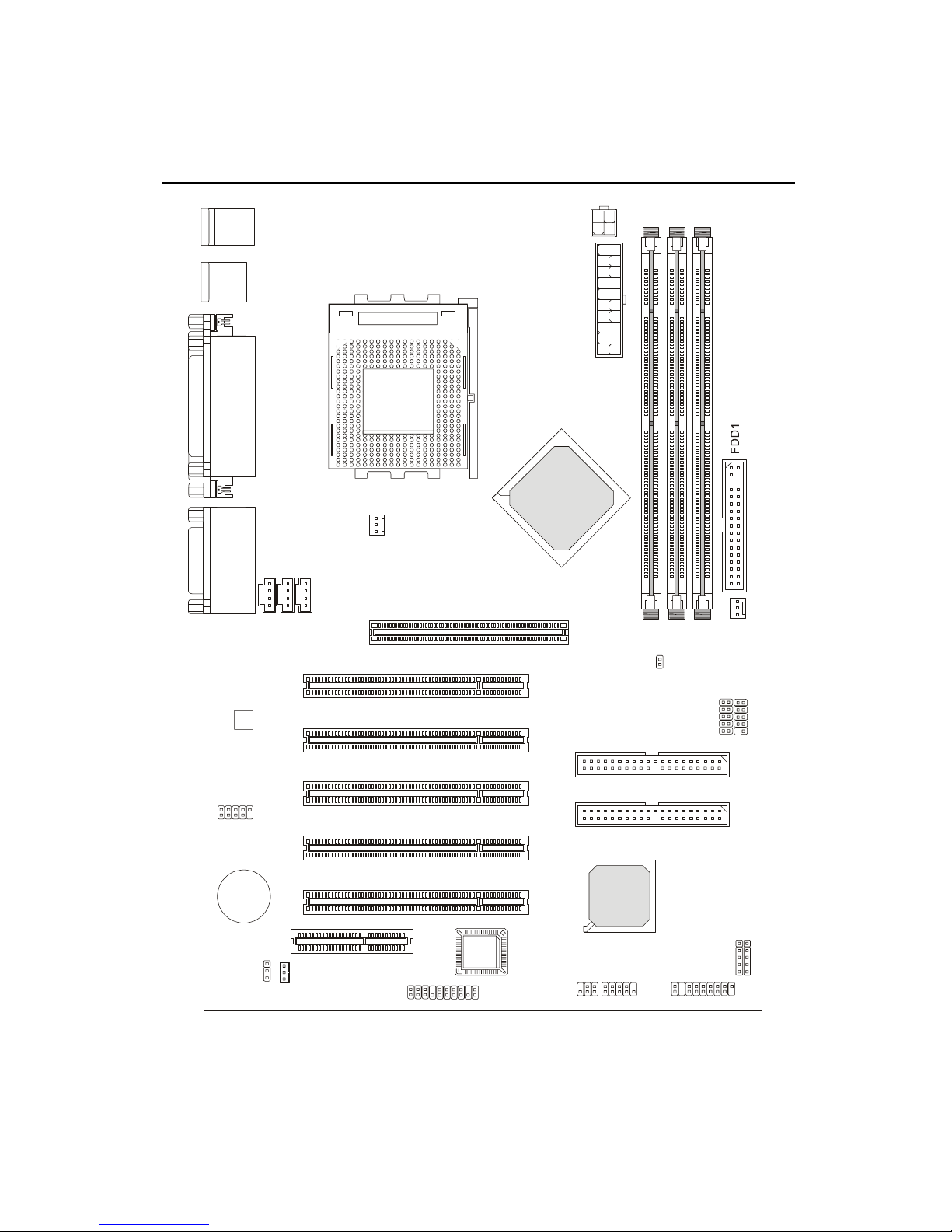
A
A
Mainboard Layout
To p : m ou se
Bottom: keyboard
USB
ports
Top : Parallel Port
Bottom:
COM A
COM B
To p :
Game port
Bottom:
Line-Out
Line-In
Mic
1
D
C
J
JPW1
TX
Power Supply
SOCKET 462
VIA
KT133A
C_FAN1
1
1
X
N
U
H
A
P
J
_
J
GP Slot
PCI Slot 1
1
M
M
I
D
J17
S_FAN1
2
3
M
M
M
M
I
I
D
D
Codec
J21(o ption al)
BATT
+
JBAT1
PCI Slot 2
PCI Slot 3
PCI Slot 4
PCI Slot 5
CNR
BIOS
JWOL1
JA10
MS-6330 (v5.X) ATX Mainboard
IR1
VT686B
F_P2
IDE 1
IDE 2
USB1
JFP1
USB3
1
M
D
M
J
2
J
1-4

Introduction
Quick Components Guide
Component Function Reference
DIMM1~3 Installing DIMM modules See p. 2-5~2-6
Socket 462 Installing CPU See p. 2-2~2-4
C_FAN1 Connecting to CPU FAN See p. 2-21
S_FAN1 Connecting to SYSTEM FAN See p. 2-21
ATX Power Supply Installing power supply See p. 2-7
JPW1 Connecting to 12V ATX power supply See p. 2-8
IDE1& IDE2 Connecting to IDE hard disk drives See p. 2-14
FDD1 Connecting to floppy disk drive See p. 2-13
USB1/3 Connecting to USB interfaces See p. 2-19
PCI Slot 1~5 Installing PCI expansion cards See p. 2-28
AGP Slot Installing AGP cards See p. 2-28
CNR Slot Installing CNR cards See p. 2-28
JMDM1 Connecting to modem module See p. 2-17
JWOL1 Connecting to LAN module See p. 2-17
JBAT1 Clearing CMOS data See p. 2-27
JFP1 & F_P2 Connecting to case See p. 2-15
J2 & IR1 Connecting to IR modules See p. 2-18
J21 Connecting to D-Bracket™ See p. 2-24
J17 Setting CPU FSB clock See p. 2-4
JA10 Connecting to audio connector See p. 2-22
1-5

Chapter 1
Key Features
l ATX Form Factor
l CPU: Socket 462 for AMD
l Memory: 3 SDRAM DIMMs
l Slot: 1 AGP slot, 1 CNR slot, 5 PCI slots
l I/O: 2 serial ports, 1 parallel port, 4 USB 1.1 ports, 1 floppy port, 2 IrDA
connectors, 1 Audio/Game port, 1 Front Audio connector, 1 D-Bracket™
connector (Optional)
l Supports Duron processors at 200/266MHz system bus frequencies
l LAN Wake up Function
l Modem (External/Internal) Ring Wake up Function
l Supports PCI 2.2
l Fuzzy Logic™ III overclocking utility
®
Duron™/Athlon™/Athlon XP Processors
l PC Alert™ III system hardware monitor
l Live BIOS™ -- allows you to update BIOS online
l Supports D-Bracket™ (Optional)
l Audio: Chip integrated
1-6

Chapter 2. Hardware Setup
Hardware Setup
Hardware Setup
This chapter provides you with the information about hardware setup
procedures. While doing the installation, be careful in holding the components and follow the installation procedures. For some components, if you
install in the wrong orientation, the components will not work properly.
Use a grounded wrist strap before handling computer components.
Static electricity may damage the components.
This chapter contains the following topics:
Central Processing Unit (CPU) 2-2
Memory 2-5
Power Supply 2-7
Back Panel 2-9
Connectors 2-13
Jumpers 2-27
Slots 2-28
2
2-1
Chapter 2
Central Processing Unit: CPU
The mainboard supports AMD® Athlon™/Athlon XP/Duron™ proces-
sors. It uses a CPU socket called Socket A for easy CPU installation. Make
sure the CPU has a Heat Sink and a cooling fan attached on the top to
prevent overheating. If you do not find the Heat Sink and cooling fan,
contact your dealer to purchase and install them before turning on the
computer.
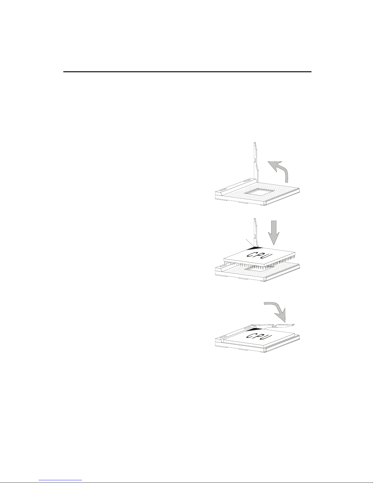
Open Lever
CPU Installation Procedures
1. Pull the lever sideways away
from the socket. Then, raise
the lever up to a 90-degree
angle.
2. Look for the cut edge. The
cut edge should point
towards the lever pivot. The
CPU will only fit in the
correct orientation.
3. Hold the CPU firmly, and
then press the lever down to
complete the installation.
Sliding
Plate
Cut edge
Close
Lever
2-2

Hardware Setup
WARNING! Thermal Issue for CPU
As processor technology pushes to faster speeds and higher performance,
thermal management becomes increasingly crucial when building computer
systems. Maintaining the proper thermal environment is key to reliable
operation. As such, the processor must be maintained in the specified thermal
requirements.
AMD Athlon™/Duron™/Athlon XP processor with a speed of 600MHz and
above requires LARGER heatsink and fan. You also need to add thermal grease
between the CPU and heatsink to improve heat dissipation. Then, make sure
that the CPU and heatsink are securely fastened and in good contact with each
other. These are needed to prevent damaging the processor and ensuring
reliable operation. If you want to get more information on the proper cooling,
you can visit AMD’s website for reference.
2-3
Chapter 2
CPU Core Speed Derivation Procedure
If CPU Clock = 100MHz
Core/Bus ratio = 7
then CPU core speed = Host Clock x Core/Bus ratio
= 100MHz x 7
= 700MHz
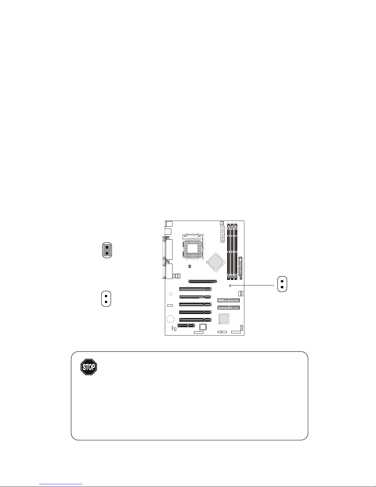
CPU Clock Frequency Selection Jumper: J17
The default hardware configuration for CPU Front Side Bus frequency
is set at 100MHz. Therefore, to use a 133MHz CPU and have it run at 133MHz,
you need to adjust the CPU clock up to 133MHz by changing the setting of J17.
For CPU FSB 100MHz
(Short)
For CPU FSB 133MHz
(Open)
Overclocking
This motherboard is designed to support overclocking.
WARNING!
However, please make sure your components are able
to tolerate such abnormal setting, while doing
overclocking. Any attempt to operate beyond product
specifications is not recommended. We do not guaran-
tee the damages or risks caused by inadequate operation or beyond product specifications.
J17
2-4
Hardware Setup
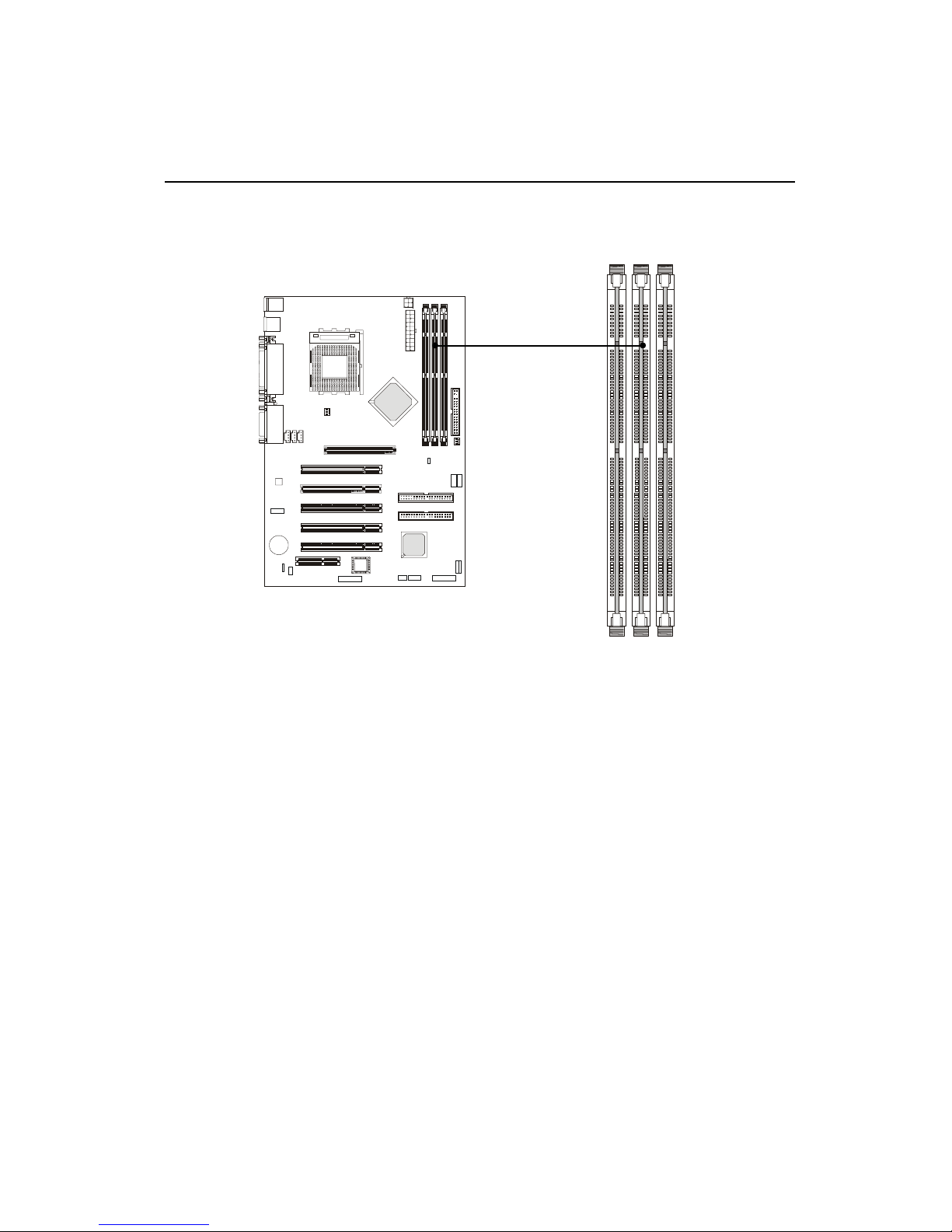
Memory
The mainboard provides 3 sockets for 168-pin unbuffered SDRAM
DIMM (Double In-Line Memory Module) modules and supports a maximum
memory size of 1.5GB.
DIMM Slots
(DIMM 1~3)
Introduction to SDRAM
Synchronous DRAM (SDRAM) is a type of dynamic RAM memory
chip that has been widely used starting in the latter part of the 1990s. SDRAMs
are based on standard dynamic RAM chips, but have sophisticated features
that make them considerably faster. First, SDRAM chips are fast enough to be
synchronized with the CPU's clock, which eliminates wait states. Second, the
SDRAM chip is divided into two cell blocks, and data is interleaved between
the two so that while a bit in one block is being accessed, the bit in the other is
being prepared for access. This allows SDRAM to burst the second and
subsequent, contiguous characters at a rate of 10ns, compared to 60ns for the
first character.
SDRAM provides 800 MBps or 1 GBps data transfer depending on
whether the bus is 100MHz or 133MHz.
2-5
Chapter 2
DIMM Modules Combination
At least one DIMM module should be installed on the motherboard.
Memory modules can be installed on the slots in any order. The single-/
double-sided memory modules that each DIMM slot supports are listed as
below:
Socket Memory Module Total Memory
DIMM 1
(Bank0 & Bank1)
DIMM 2
(Bank2 & Bank3)
DIMM 3
(Bank4 & Bank5)
Maximum System Memory Supported 32MB ~ 1.5GB
S: Single Side D: Double Side
S/D 32MB ~ 512MB
S/D 32MB ~ 512MB
S/D 32MB ~ 512MB
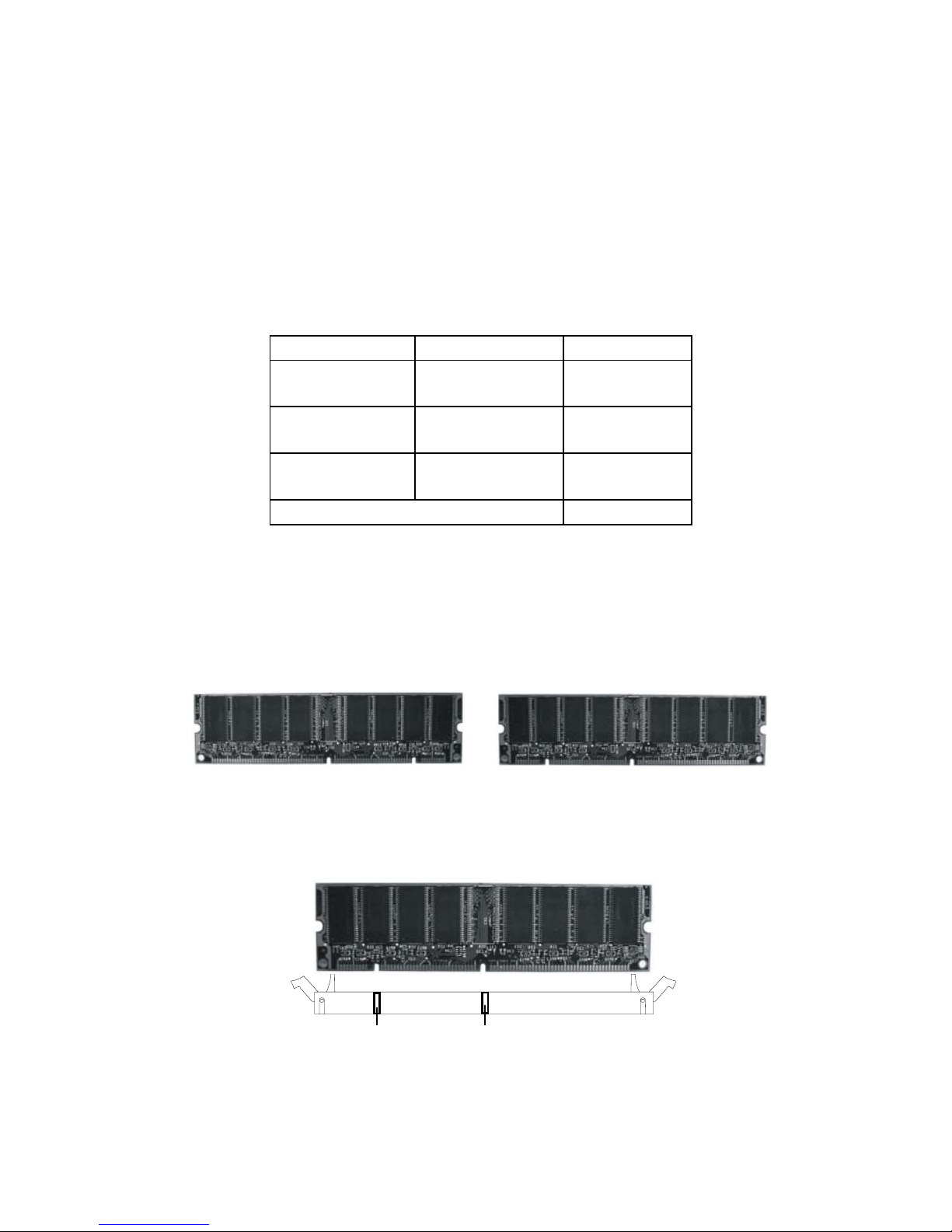
Installing DIMM Modules
1. The DIMM slot has 2 Notch Keys “VOLT and DRAM”, so the DIMM
memory module can only fit in one direction.
Front View Rear View
2. Insert the DIMM memory module vertically into the DIMM slot. Then
push it in.
VOLTDRAM
3. The plastic clip at each side of the DIMM slot will automatically
close.
2-6
Hardware Setup
Power Supply
The mainboard supports ATX power supply for the power system.
Before inserting the power supply connector, always make sure that all components are installed properly to ensure that no damage will be caused.
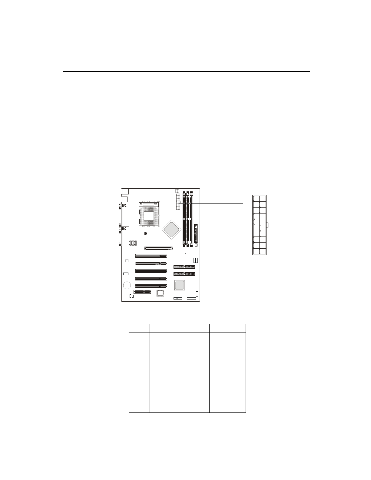
ATX 20-Pin Power Supply
This connector allows you to connect to an ATX power supply. To
connect to the ATX power supply, make sure the plug of the power supply is
inserted in the proper orientation and the pins are aligned. Then push down
the power supply firmly into the connector.
PIN SIGNAL
1 3.3V
2 3.3V
3 GND
45V
5 GND
65V
7 GND
8 PW_OK
9 5V_SB
10 12V
ATX
Power Connector
PIN SIGNAL
11 3.3V
12 -12V
13 GND
14 PS_ON
15 GND
16 GND
17 GND
18 -5V
19 5V
20 5V
10
1
20
11
2-7
Chapter 2
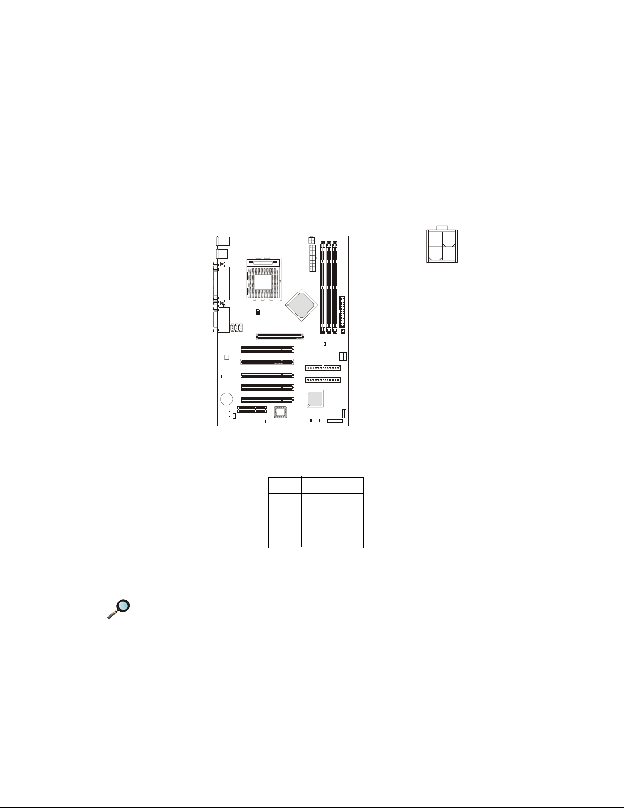
ATX 12V Power Connector: JPW1
Attach the ATX power supply to the connector and it will supply power
to the installed CPU.
PIN SIGNAL
1 GND
2 GND
3 12V
4 12V
3
12
4
JPW1
Note: Power current supplied via 12V power connector must exceed
10A.; otherwise, the system could have a stability issue.
2-8
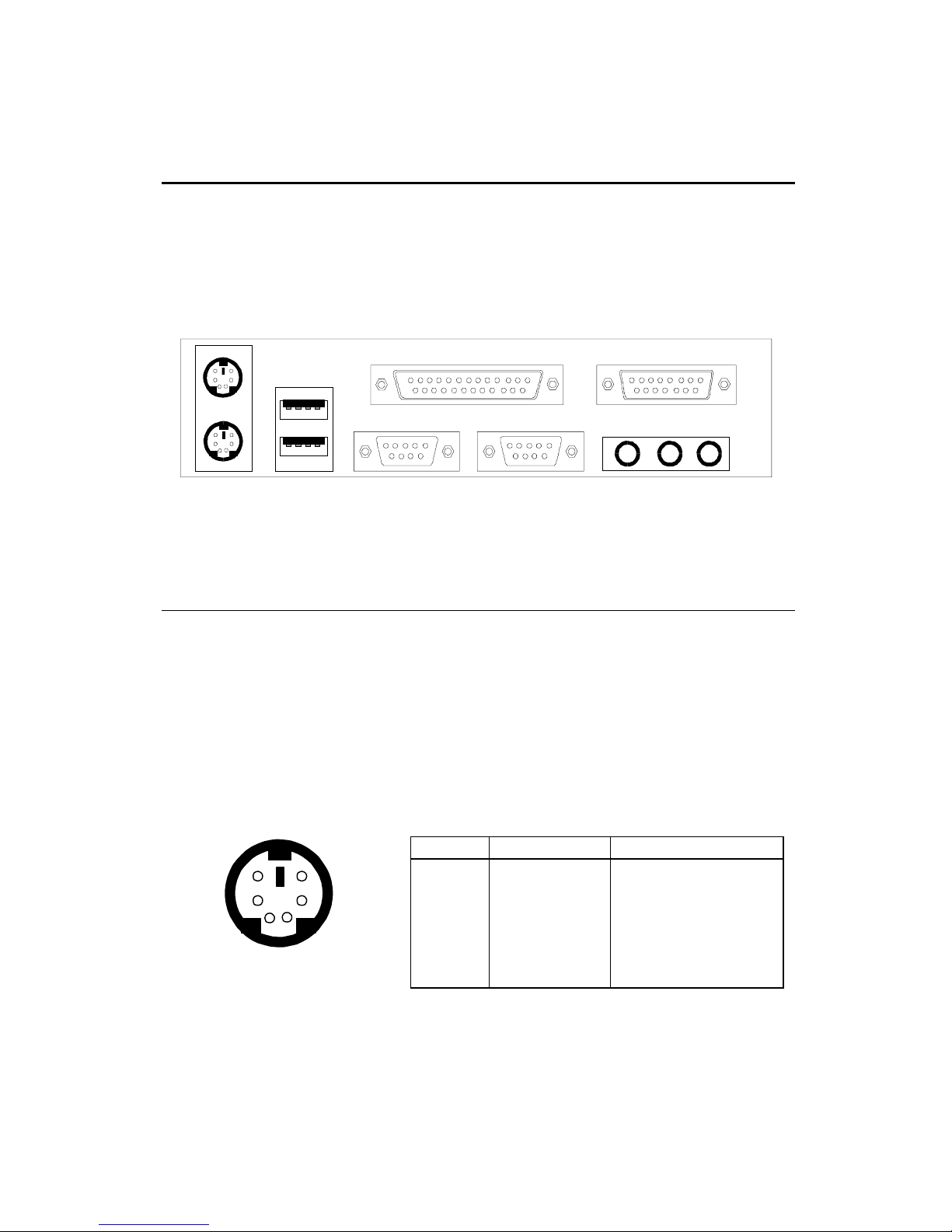
Back Panel
The Back Panel provides the following connectors:
Hardware Setup
Mouse
Keyboard USB
Parallel
COM A COM B L-out L-in
Midi/Joystick
MIC
Mouse Connector
The mainboard provides a standard PS/2® mouse mini DIN connector
for attaching a PS/2® mouse. You can plug a PS/2® mouse directly into this
connector.
6
4
2
PS/2 Mouse (6-pin Female)
Pin Definition
PIN SIGNAL DESCRIPTION
5
3
1
1 Mouse DATA Mouse DATA
2 NC No connection
3 GND Ground
4 VCC +5 V
5 Mouse Clock Mouse clock
6 NC No connection
2-9
Chapter 2
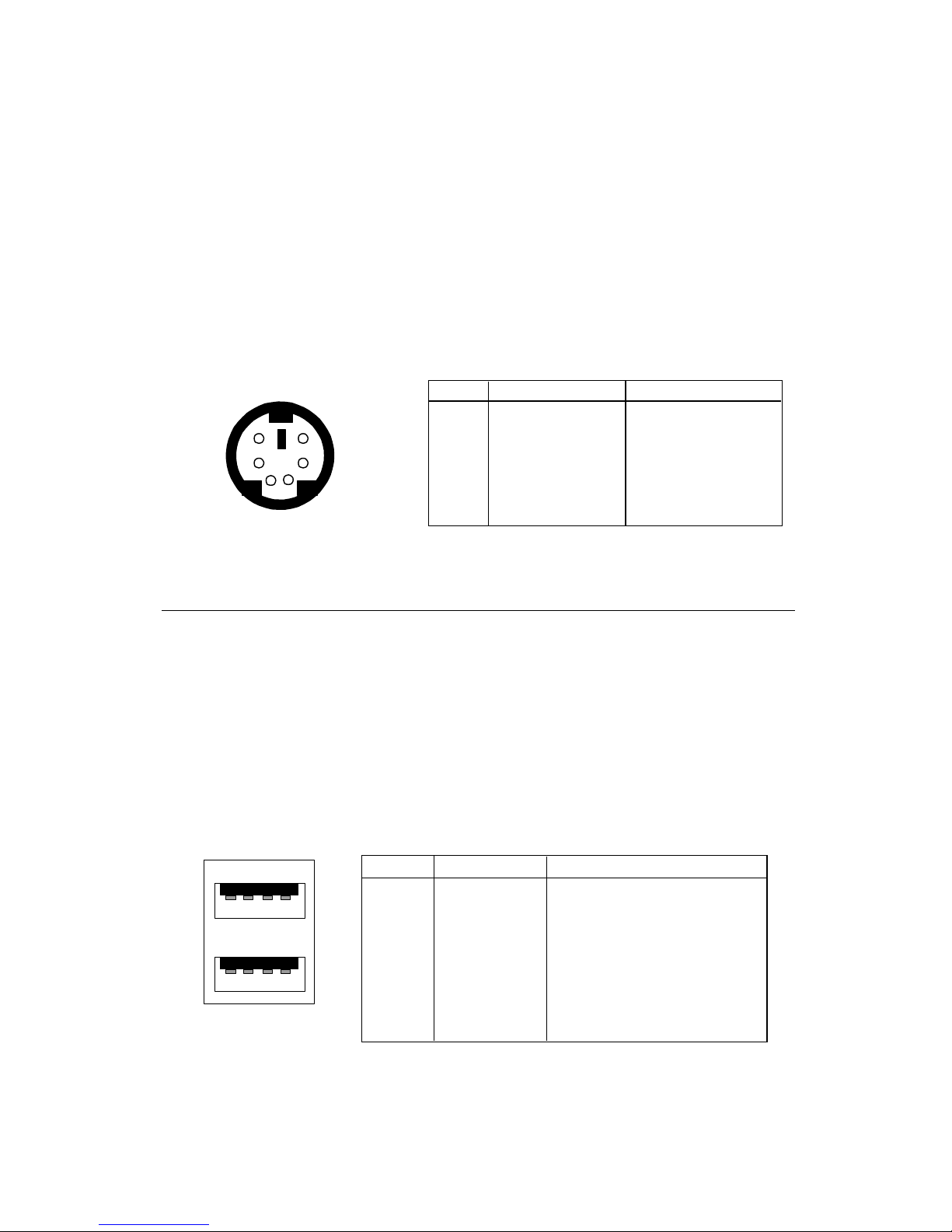
Keyboard Connector
The mainboard provides a standard PS/2® keyboard mini DIN connector for attaching a PS/2® keyboard. You can plug a PS/2® keyboard directly into
this connector.
Pin Definition
PIN SIGNAL DESCRIPTION
6
21
PS/2 Keyboard (6-pin Female)
5
34
1 Keyboard DATA Keyboard DATA
2 NC No connection
3 GND Ground
4 VCC +5V
5 Keyboard Clock Keyboard clock
6 NC No connection
USB Connectors
The mainboard provides a UHCI (Universal Host Controller Interface)
Universal Serial Bus root for attaching USB devices such as keyboard, mouse
or other USB-compatible devices. You can plug the USB device directly into
ths connector.
USB Port Description
1 2 3 4
5 6 7 8
USB Ports
PIN SIGNAL DESCRIPTION
1 VCC +5V
2 -Data 0 Negative Data Channel 0
3 +Data0 Positive Data Channel 0
4 GND Ground
5 VCC +5V
6 -Data 1 Negative Data Channel 1
7 +Data 1 Positive Data Channel 1
8 GND Ground
2-10
Hardware Setup
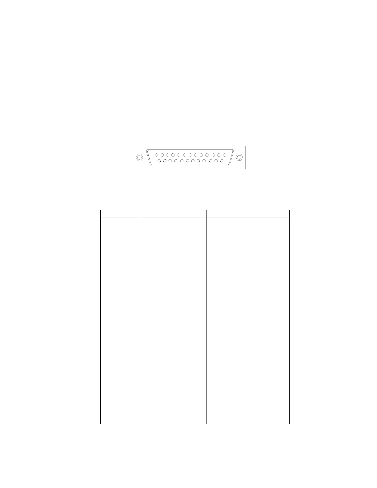
Parallel Port Connector
The mainboard provides a 25-pin female centronic connector for LPT.
A parallel port is a standard printer port that supports Enhanced Parallel Port
(EPP) and Extended Capabilities Parallel Port (ECP) mode.
13
1
1425
Pin Definition
PIN SIGNAL DESCRIPTION
1 STROBE Strobe
2 DATA0 Data0
3 DATA1 Data1
4 DATA2 Data2
5 DATA3 Data3
6 DATA4 Data4
7 DATA5 Data5
8 DATA6 Data6
9 DATA7 Data7
10 ACK# Acknowledge
11 BUSY Busy
12 PE Paper End
13 SELECT Select
14 AUTO FEED# Automatic Feed
15 ERR# Error
16 INIT# Initialize Printer
17 SLIN# Select In
18 GND Ground
19 GND Ground
20 GND Ground
21 GND Ground
22 GND Ground
23 GND Ground
24 GND Ground
25 GND Ground
2-11
 Loading...