

MS-6119 ATX BX2 Mainboard
MICRO-STAR INTERNATIONAL COMPANY LTD.
Specification & User’s Guide
MS-6119 ATX BX2 Mainboard
Specification & User’s Guide
1. Introduction
The MSI ATX BX2 mainboard is a high-performance personal computer mainboard
based on the Pentium
®
II processor. The Pentium® II processor supports MMX
TM
(Multime-
dia Extension) technology.
The mainboard uses the highly integrated Intel
®
82443BX AGP chipset to support
the PCI/ISA and Green standards, and to provide the Host/AGP bridge. The Intel
®
82371AB chipset integrates all system control functions such as ACPI (Advanced Configuration and Power Interface). The ACPI provides more Energy Saving Features for the
OSPM(OS Direct Power Management) function. The Intel
®
82371EB chipset also improves
the IDE transfer rate by supporting Ultra DMA/33 IDE that transfers data at the rate of
33MB/s.
The mainboard also supports the LM78 System Hardware Monitor Controller as an
optional function. The LM78 function includes: CPU /power supply/chassis fan revolution
detect, CPU/system voltage monitor, system temperature monitor, and chassis intrusion
detect(optional).
MICRO-STAR
INTERNATIONAL
COMPANY LTD.
MICRO-STAR
INTERNATIONAL
COMPANY LTD.
Specification & User’s Guide
1

MS-6119 ATX BX2 Mainboard
MICRO-STAR INTERNATIONAL COMPANY LTD.
Specification & User’s Guide
2
Table of Contents
1. Introduction.............................................................................................................................1
2. Mainboard Specification...........................................................................................................3
3. Mainboard Layout..................................................................................................................6
4. Backpanel Layout.................................................................................................................7
4.1 Connectors................................................................................................................7
4.1-1 Mouse Connector......................................................................................7
4.1-2 Keyboard Connector.................................................................................8
4.1-3 USB Connectors..........................................................................................8
4.1-4 Parallel Port Connector.............................................................................9
4.1-5 Serial Port Connectors..............................................................................10
5. Slot 1....................................................................................................................................11
6. DIMM DRAM Addressing..................................................................................................15
7, CPU Fan Power Connector..................................................................................................16
8. Irda Infrared Module Connector......................................................................................... 16
Appendixes

MS-6119 ATX BX2 Mainboard
MICRO-STAR INTERNATIONAL COMPANY LTD.
Specification & User’s Guide
2. Mainboard Specification
l Slot 1 for Pentium
®
II Processor .
l Supports 200MHz, 233MHz, 266MHz, 300MHz,
333MHz, and faster.
l Core/Bus ratios are x2, x2.5, x3, x3.5, x4, x4.5,
x5, x5.5, x6 and higher.
CPU
l On-board switching mode DC-DC Step Down
Regulator.
l Conforms to Intel
®
VRM ver 8.2 specifications.
l Over-Voltage and Over-Current protection.
Switching Voltage
Regulator
l Intel
®
82443BX AGP chipset.
Chipset
l 66.6MHz and 100MHz clocks are supported.
(75 MHz and 83MHz reserved)
Clock Generator
l Supports eight memory banks using three 168-
pin unbuffered DIMM sockets.
l Supports a maximum memory size of 384MB
(8M x 8) or 768MB(16M x 4) registered DIMM
only.
l Supports ECC(1-bit Error Code Correct) and
EC(Multiple-Bit Error Checking) function.
l Supports 3.3v SDRAM DIMM.
Main Memory
l One AGP(Accelerated Graphics Port) slot.
- AGP specification compliant
- AGP 66/133MHz 3.3v device support
l Four 32-bit Master PCI Bus slots and three 16-bit
ISA bus slots wherein one shared slot can be used
as ISA or PCI.
l Supports 3.3v/5v PCI bus Interface.
Slots
l An IDE controller on the Intel
®
82371EB PCI
Chipset provides IDE HDD/CD-ROM with PIO,
Bus Master and Ultra DMA/33 operation modes.
l Can connect up to four IDE devices.
On-Board IDE
FEATURES
SPECIFICATIONS
3

MS-6119 ATX BX2 Mainboard
MICRO-STAR INTERNATIONAL COMPANY LTD.
Specification & User’s Guide
FEATURES
SPECIFICATIONS
l On-Board Peripherals include:
- 1 floppy port supports 2 FDD with 360K,
720K, 1.2M, 1.44M and 2.88Mbytes.
- 2 serial ports (COMA + COMB)
- 1 parallel port supports SPP/EPP/ECP
mode
- 2 USB ports
- 1 IrDA connector for Fast IrDA(reserved).
On-Board Peripherals
l The mainboard BIOS provides “Plug & Play”
BIOS which detects the peripheral devices and
expansion cards of the board automatically.
l The mainboard provides a Desktop Management
Interface(DMI) function which records your
mainboard specifications.
BIOS
l CPU/Power Supply/Chassis Fan Revolution
Detect
l CPU Fan Control (the fan will automatically
stop when the system enters suspend mode)
l System Voltage Detect
l CPU Overheat Warning (reserved)
l Chassis Intrusion Detect(reserved)
l Display Actual Current Voltage
On-Board System
Hardware
Monitor(LM78)
l PIIX4(82371EB) built-in RTC.
RTC
Keyboard Connector
l PS/2
®
keyboard interface and PS/2® mouse interface.
Mounting
l ATX Form Factor: 30cm(L) x 18.6cm(W) x 4
layers PCB.
l Double deck PS/2
®
keyboard & PS/2® mouse.
l Double deck USB port.
l Double deck Serial & LPT port.
l Double deck I/O connectors, compatible with
Intel
®
Venus Mainboard.
l 6 mounting holes.
Dimension
4
MS-6119 ATX BX2 Mainboard
MICRO-STAR INTERNATIONAL COMPANY LTD.
Specification & User’s Guide
FEATURES
SPECIFICATIONS
l Keyboard Password Wake-Up
l LAN Wake-Up
l Internal/External Modem Wake-Up
Other features
5
MS-6119 ATX BX2 Mainboard
MICRO-STAR INTERNATIONAL COMPANY LTD.
Specification & User’s Guide
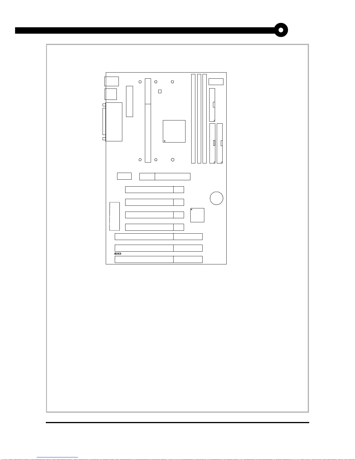
DIMM 1
Top: mouse
Bottom:
keyboard
Top: Port 1
USB
Top: LPT
Bottom:
COM A
COM B
DIMM 2
DIMM 3
ISA SLOT
ISA SLOT
PCI SLOT 4
PCI SLOT 3
PCI SLOT 2
PCI SLOT 1
SLOT 1
ISA SLOT
FDC
BATT
+
IDE2
IDE1
LM75
(optional)
ATX
Power Supply
BIOS
FW82371EB
FW82443BX
Clock
Generator
AGP
Bottom:
Port 2
3. Mainboard Layout
6
JMDM1
DIMM Clock
buffers
MS-6119 ATX BX2 Mainboard
MICRO-STAR INTERNATIONAL COMPANY LTD.
Specification & User’s Guide
7
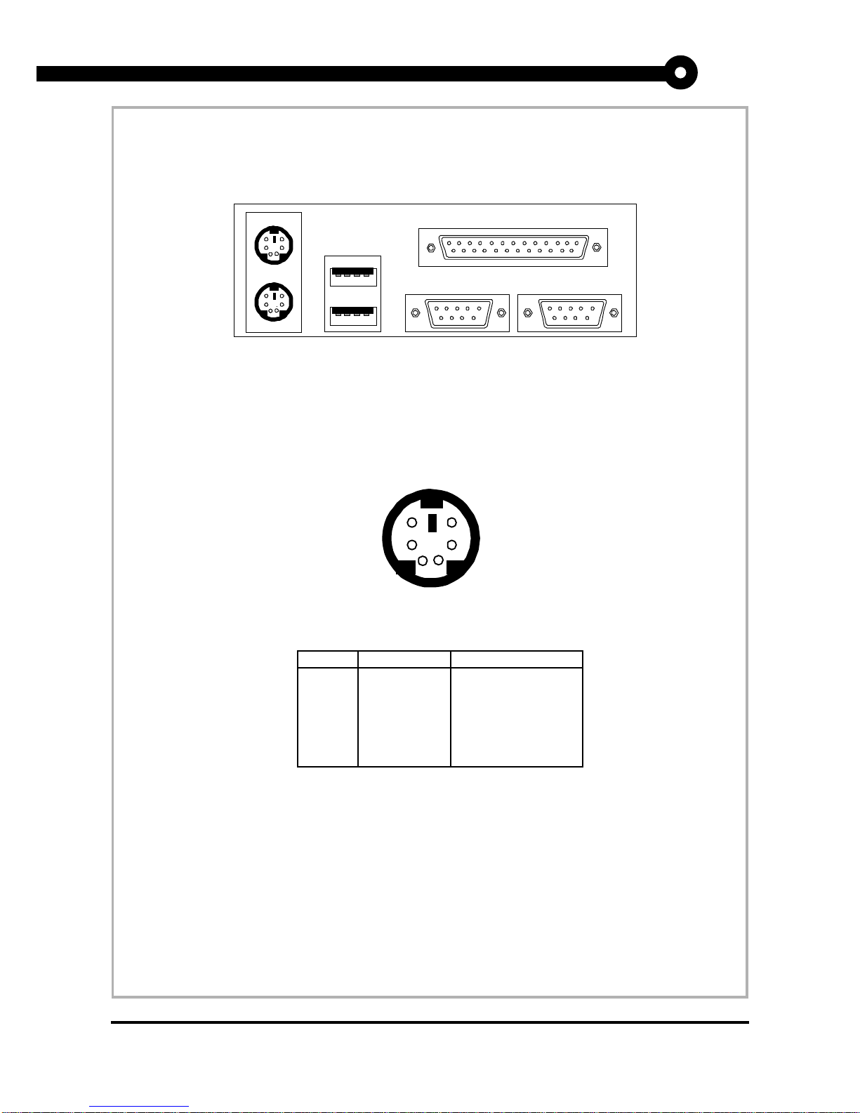
4. Backpanel Layout
Mouse
Keyboard USB
Parallel
COM A
COM B
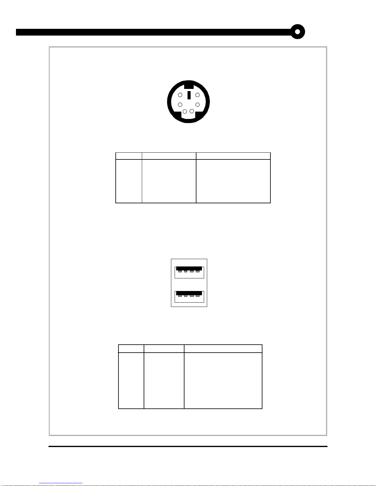
4.1-1 Mouse Connector
4.1 Connectors
PS/2 Mouse (6-pin Female)
2
1
3
4
5
PIN SIGNAL DESCRIPTION
1 Mouse DATA Mouse DATA
2 NC No connection
3 GND Ground
4VCC +5V
5 Mouse Clock Mouse clock
6 NC No connection
6
PS/2 Mouse Pin Definition
MS-6119 ATX BX2 Mainboard
MICRO-STAR INTERNATIONAL COMPANY LTD.
Specification & User’s Guide
8
4.1-2 Keyboard Connector
PS/2 Keyboard (6-pin Female)
2
1
3
4
5
PIN SIGNAL DESCRIPTION
1 Keyboard DATA Keyboard DATA
2 NC No connection
3 GND Ground
4 VCC +5V
5 Keyboard Clock Keyboard clock
6 NC No connection
6
PS/2 Keyboard Pin Definition
4.1-3 USB Connectors
USB Ports
1 2 3 4
PIN SIGNAL DESCRIPTION
1 VCC +5V
2 -Data 0 Negative Data Channel 0
3 GND Ground
4 +Data 0 Positive Data Channel 0
5 VCC +5V
6 +Data 1 Positive Data Channel 1
7 -Data 1 Negative Data Channel 1
8 GND Ground
5 6 7 8
USB Port Description
MS-6119 ATX BX2 Mainboard
MICRO-STAR INTERNATIONAL COMPANY LTD.
Specification & User’s Guide
9
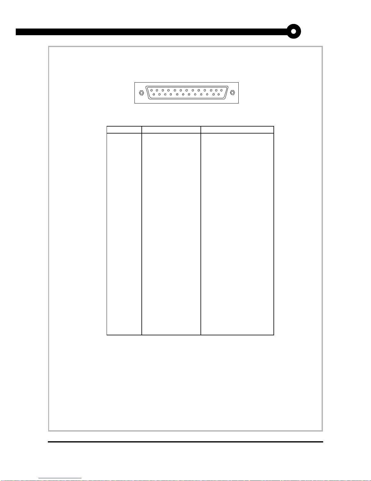
4.1-4 Parallel Port Connector
13
LPT 25-Pin Male Connectors
PIN SIGNAL DESCRIPTION
1 STROBE Strobe
2 DATA0 Data0
3 DATA1 Data1
4 DATA2 Data2
5 DATA3 Data3
6 DATA4 Data4
7 DATA5 Data5
8 DATA6 Data6
9 DATA7 Data7
10 ACK# Acknowledge
11 BUSY Busy
12 PE Paper End
13 SELECT Select
14 AUTO FEED# Automatic Feed
15 ERR# Error
16 INIT# Initialize Printer
17 SLIN# Select In
18 GND Ground
19 GND Ground
20 GND Ground
21 GND Ground
22 GND Ground
23 GND Ground
24 GND Ground
25 GND Ground1
1
14
25
MS-6119 ATX BX2 Mainboard
MICRO-STAR INTERNATIONAL COMPANY LTD.
Specification & User’s Guide
10
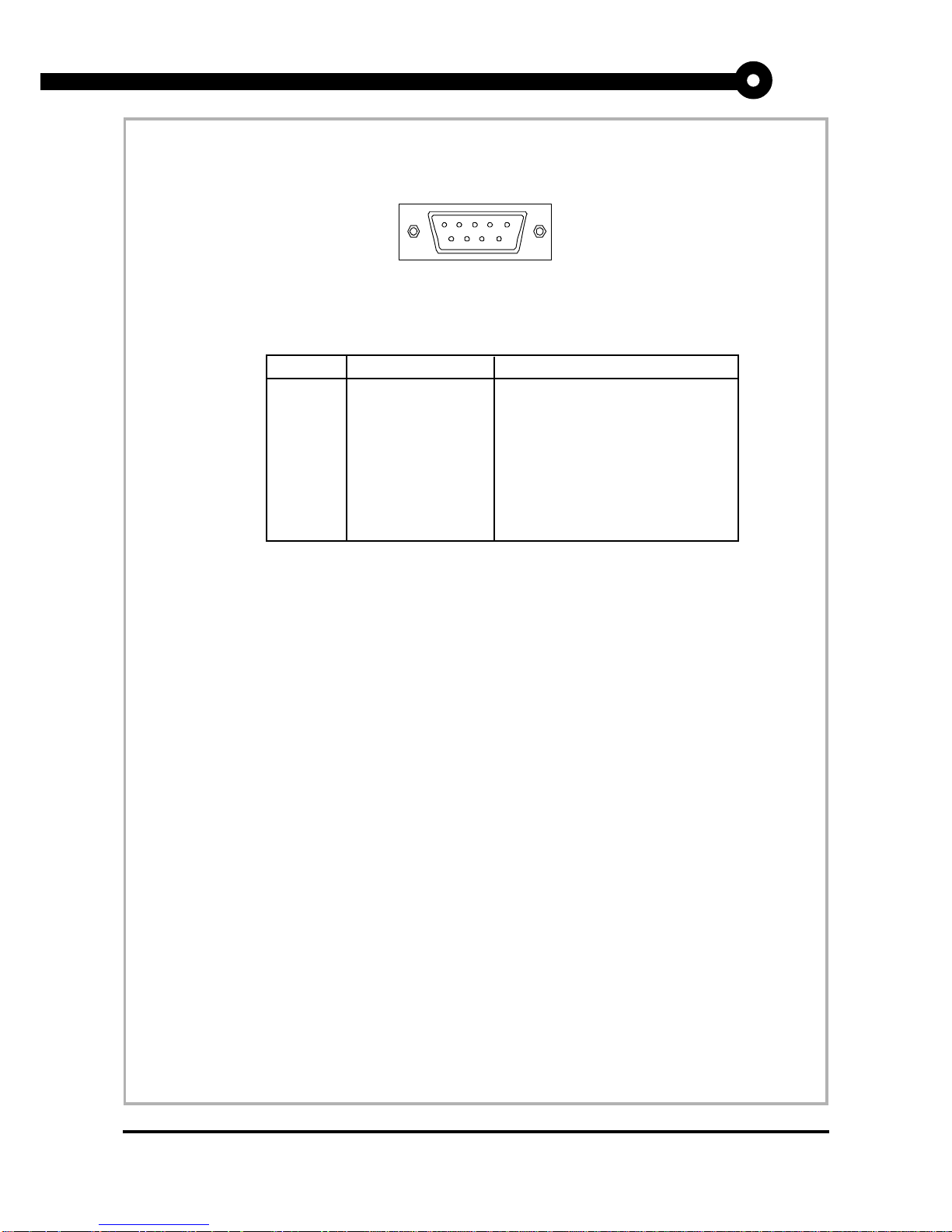
4.1-5 Serial Port Connectors
1 2 3 4 5
COM A / COMB 9-Pin male DIN connectors
PIN SIGNAL DESCRIPTION
1 DCD Data Carry Detect
2 SIN Serial In or Receive Data
3 SOUT Serial Out or Transmit Data
4 DTR Data Terminal Ready)
5 GND Ground
6 DSR Data Set Ready
7 RTS Request To Send
8 CTS Clear To Send
9 RI Ring Indicate
6 7 8 9
 Loading...