


CHAPTER 1 INTRODUCTION
Chapter 1
INTRODUCTION
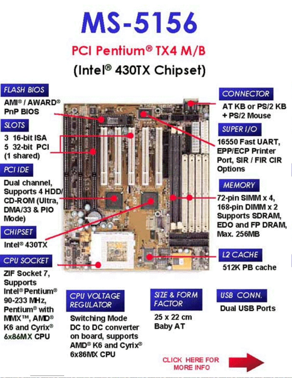
The MS-5156 mainboard is a high-performance personal computer
mainboard. The mainboard supports the Peripheral Component Interconnect
(PCI) Local Bus standard and provides five 32-bit PCI bus slots.
The mainboard uses the highly integrated Intel® 83430TX chipset to support
the PCI/ISA and Green standards, and to provide the Host/PCI bridge. The
Intel® 82430TX chipset integrates all system control functions.
1-1

CHAPTER 1 INTRODUCTION
1.1 System Board Features
CPU
l Socket 7 supports Intel® Pentium® processors and Pentium® processors
with MMX™ technology
l The Cyrix
®
6x86/6x86L/6x86MX and AMD® K5/K6 are also supported.
Chipset
l Intel
®
82430 TX chipset.
Cache Memory
l Supports 512K pipelined burst cache memory.
l Supports Direct Map Organization and Write-Back cache policy .
Main Memory
l Supports four memory banks using four 72-pin SIMM sockets and two
168-pin DIMM sockets (for unbuffered DIMM).
l Up to 256 Mbytes main memory.
l Supports EDO Hyper Page Mode DRAM, Standard Fast Page mode
DRAM and SDRAM(Synchronous DRAM).
Slots
l Five 32-bit PCI Bus slots (four 32-bit bus master PCI slots + one 32-bit
slave PCI slot) + Three 16-bit ISA bus slots. One shared slot can be used
as ISA or PCI.
On-Board IDE
l Supports Bus Master and Ultra DMA/33 IDE.
l Supports up to 4 IDE drives.
On-Board Peripherals
1-2

CHAPTER 1 INTRODUCTION
1-3
l On-Board Peripherals include:
- 1 floppy port supports 2 FDD
- 2 serial ports (COMA + COMB)
- 1 parallel port supports ECP or EPP mode
- USB
- IR (SIR)
Dimensions
l Baby-A T form factor
l 25cm(L) x 22cm(W) x 4 layer PCB
Mounting
l 5 mounting holes
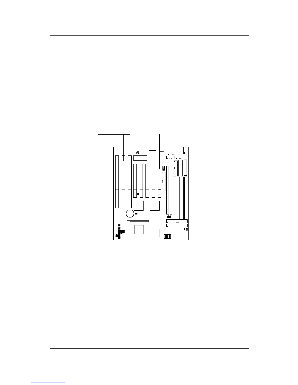
CHAPTER 1 INTRODUCTION
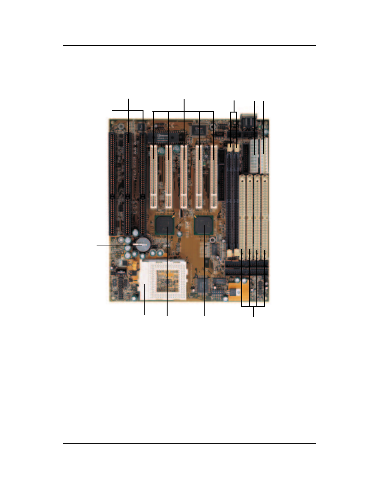
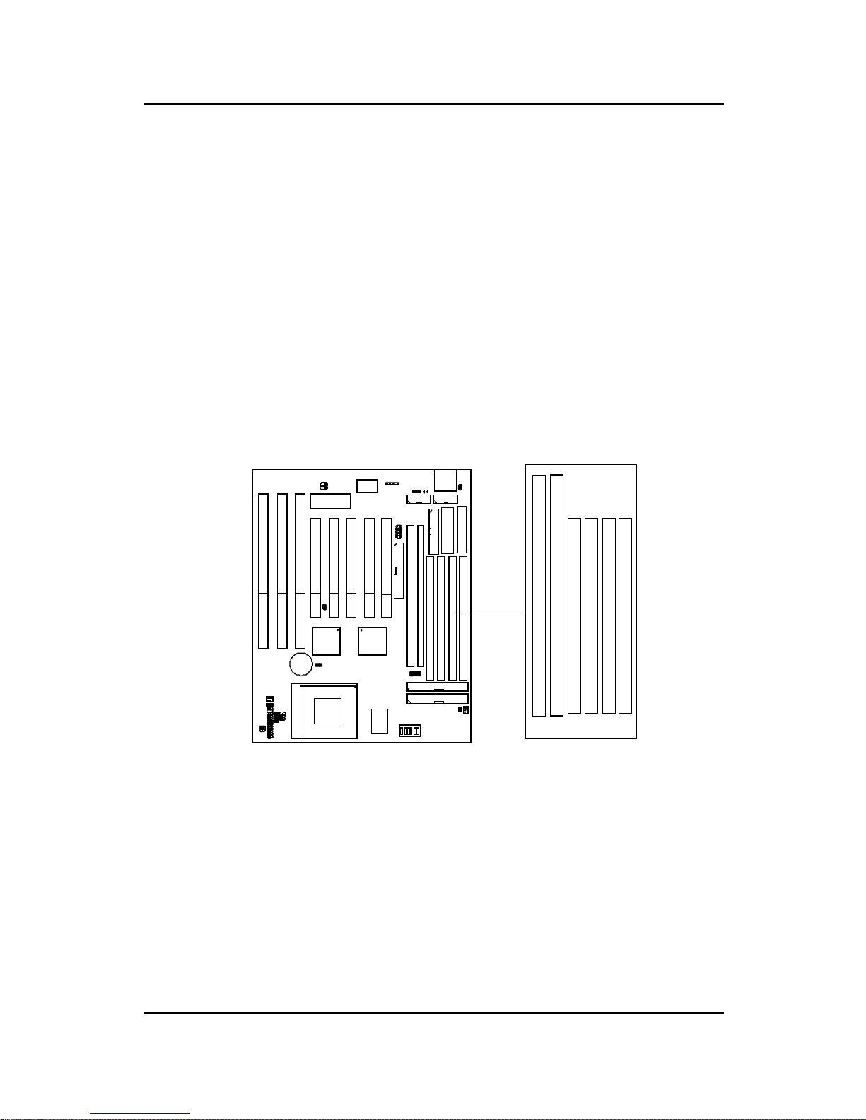
1.2 Parts of the Mainboard
ABC
DE
F
GH
I
J
A Three 16-Bit ISA SLOTs
B Five 32-Bit PCI SLOTs
C T wo 168-Pin DIMM SOCKET s
D A TX 20-Pin POWER CONNECT OR
E PS/2® POWER CONNECTOR
F Four 72-pin SIMM SOCKET s
G Intel® 82439TX
H Intel® 82371AB
I SOCKET 7
J 2032 LITHIUM BA TTERY
1-4
CHAPTER 1 INTRODUCTION
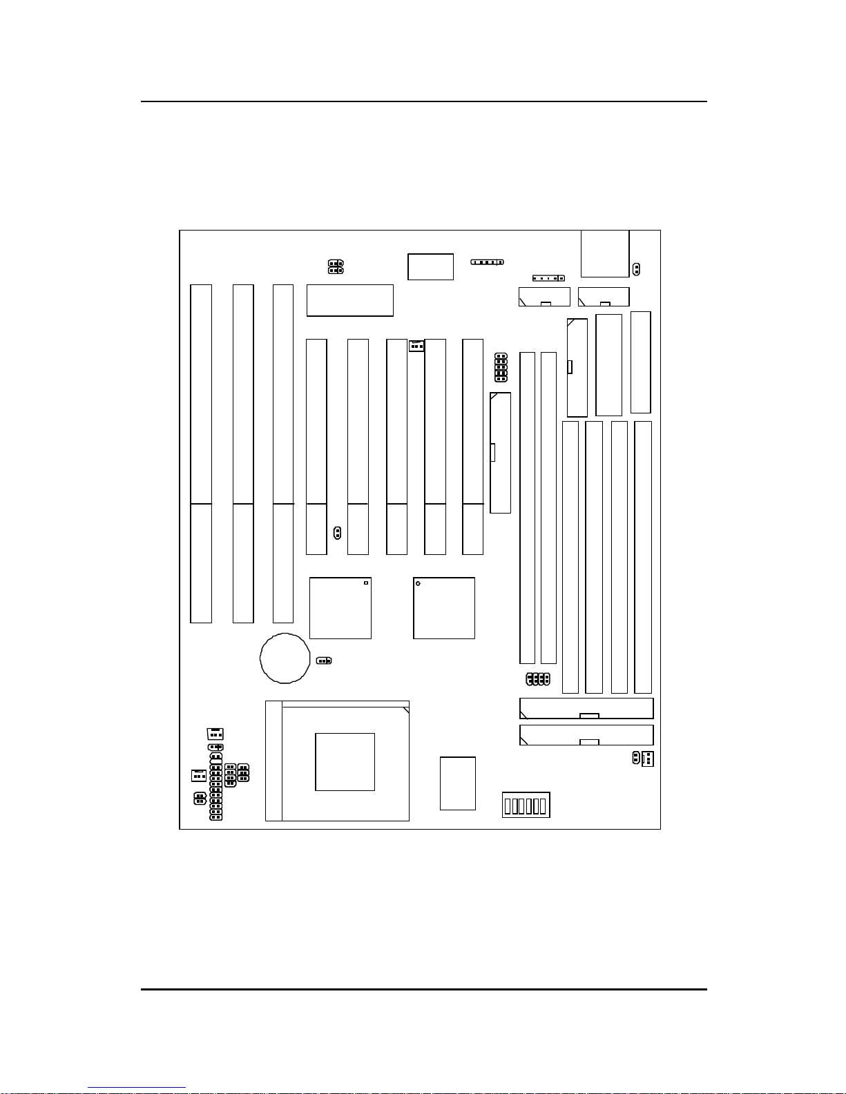
1.3 Mainboard Layout
1-5
MS-5156
ISA SLOT
ISA SLOT
ISA SLOT
PCI SLOT 5
PCI SLOT 4
PCI SLOT 3
PCI SLOT 2
PCI SLOT 1
FDC
DIMM 2
DIMM 1
SIMM 4
SIMM 1
SIMM 2
SIMM 3
LPT
A TKBD
COM A
COM B
BIOS
ATX
Power Supply
USB
Power Supply
JRMS1
JMS1
JIR1
JP2
JP1
Winbond
J10
JBAT1
FW82371AB
FW82439TX
IDE2
IDE1
BATT
+
JV1
3.3V 5V
JRMC1
JRMS2
SW1
PBSRAM
SOCKET 7
JFAN 2
JFAN 1
JGS1
JGL1
JFP1
JV8
JV2
JV3
JV4
JV5
JSFAN
JPFAN
CHAPTER 2 HARDWARE INSTALLATION
CPU
CPU
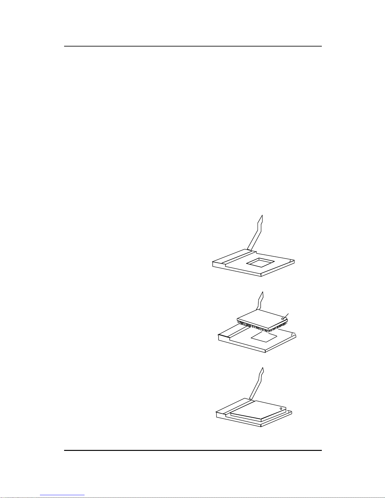
2.1-1 CPU Installation Procedures
Chapter 2
HARDWARE INSTALLATION
2.1 Central Processing Unit: CPU
The MS-5156 mainboard operates with Intel® Pentium® processors/
Pentium® processors with MMX
TM
technology, Cyrix® 6x86/6x86L/
6x86MX and AMD® K5/K6 processors. It could operate with 2.8V to
3.52V processors. The mainboard provides a 321-pin ZIF Socket 7 for easy
CPU installation, a DIP switch (SW1) to set the proper speed for the CPU
and a Jumper block (JV2 - JV5) for setting the CPU voltage. The CPU
should always have a cooling fan attached to prevent overheating.
2-1
3. Press the lever down to
complete the installation.
2 . Locate Pin 1 in the socket
and look for the white dot or
cut edge in the CPU. Match
Pin 1 with the white dot/cut
edge. Then, insert the CPU.
It should insert easily.
Open Lever
Pin 1
Sliding
Plate
White dot/
Cut edge
Close
Lever
1 . Pull the lever sideways away
from the socket. Then raise
the lever up to a 90-degree
angle.
CHAPTER 2 HARDWARE INSTALLATION
2-2
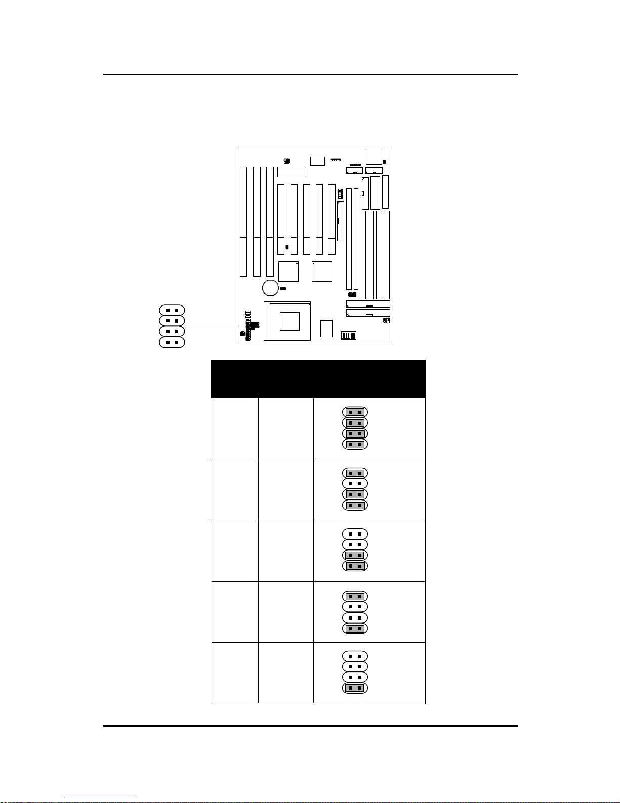
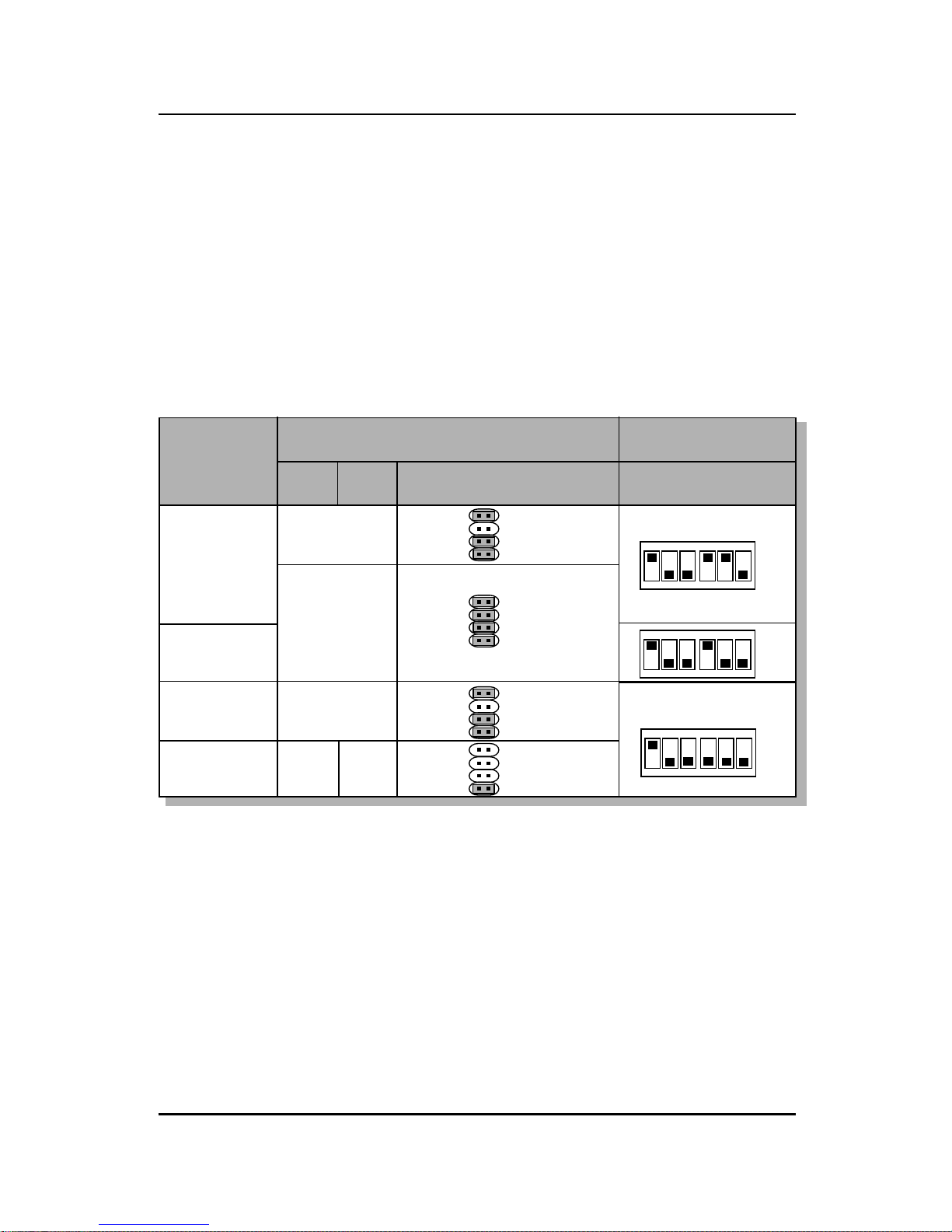
2.1-2 CPU Voltage Setting: JV2-JV5
VcoreV I/O
3.5 3.5
3.3 3.3
3.3
3.2
3.3 2.9
3.3
2.8
JV2~JV5
JV2
JV3
JV4
JV5
JV2
JV3
JV4
JV5
JV2
JV3
JV4
JV5
JV2
JV3
JV4
JV5
JV2
JV3
JV4
JV5
JV2
JV3
JV4
JV5
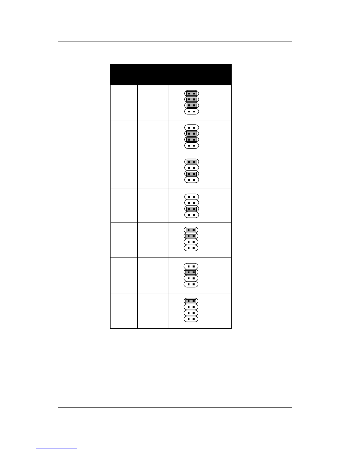
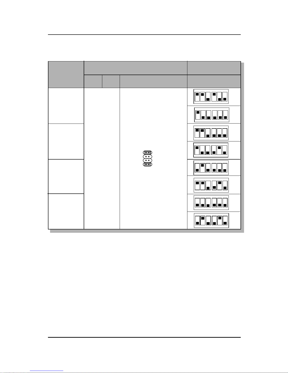
CHAPTER 2 HARDWARE INSTALLATION
VcoreV I/O
3.3 2.7
3.3 2.6
3.3 2.5
3.3
2.4
3.3
2.3
JV2~JV5
JV2
JV3
JV4
JV5
JV2
JV3
JV4
JV5
JV2
JV3
JV4
JV5
JV2
JV3
JV4
JV5
JV2
JV3
JV4
JV5
3.3
2.2
3.3
2.1
JV2
JV3
JV4
JV5
JV2
JV3
JV4
JV5
2-3
CHAPTER 2 HARDWARE INSTALLATION
To adjust the speed and voltage of the CPU, you must know the specifications of your CPU (always ask the vendor for CPU specifications). Then
refer to Table 2.1 (Intel® processors), Table 2.2 (Cyrix® processors) and
Table 2.3 (AMD® processors) for proper setting.
2.1-3 CPU Speed and Voltage Setting: SW1 & JV2-JV5
2-4
SW1
1 2 3 4 5 6
ON DIP
ON
OFF
JV2
JV3
JV4
JV5
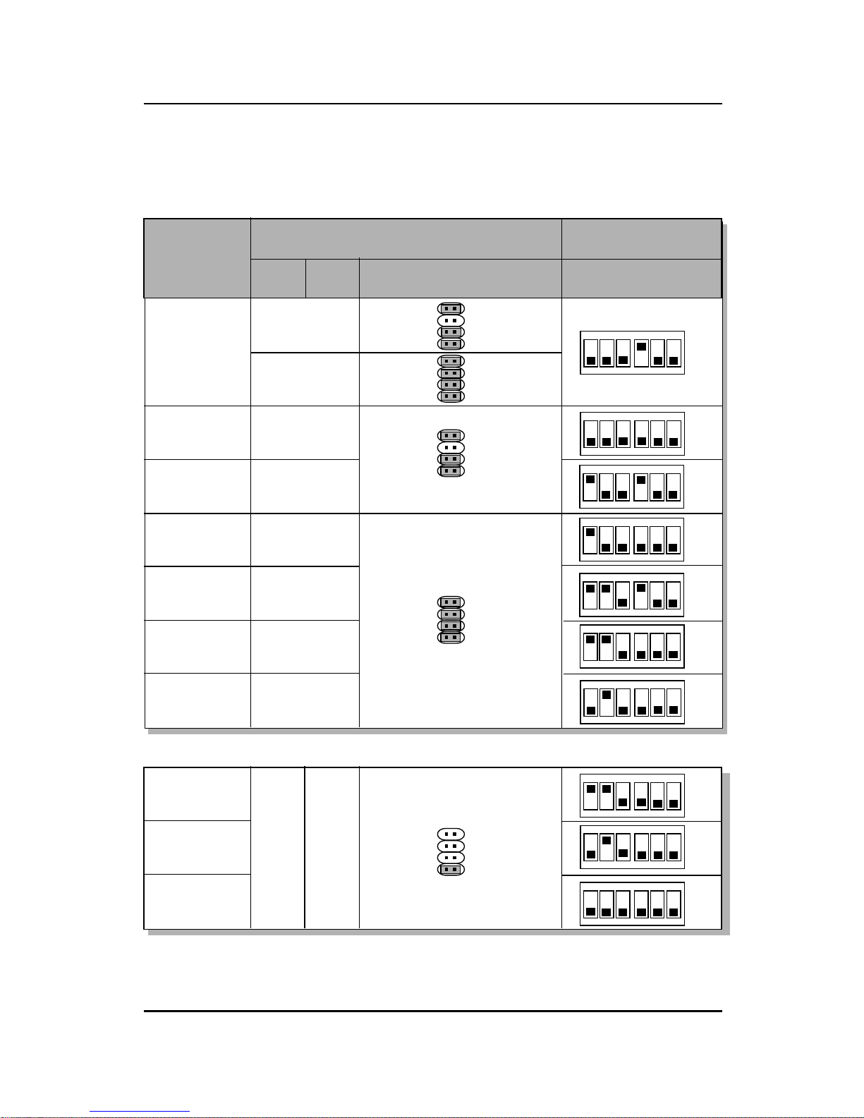
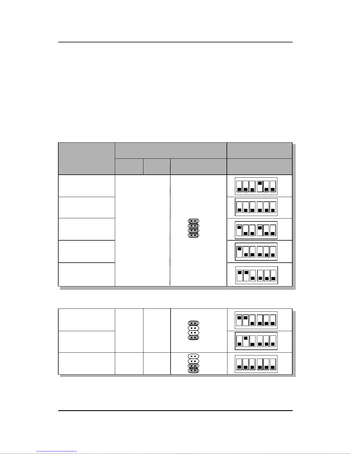
CHAPTER 2 HARDWARE INSTALLATION
Table 2.1 Intel® processors
90MHz
100MHz
120MHz
133MHz
150MHz
166MHz
200MHz
3.38
3.52
3.52
3.38
3.38
3.52
3.52
3.52
ON DIP
123 456
ON
OFF
ON DIP
123 456
ON
OFF
ON DIP
123 456
ON
OFF
ON DIP
123 456
ON
OFF
ON DIP
123 456
ON
OFF
CPU Type
CPU SpeedCPU Voltage
SW1VI/O Vcore
ON DIP
123 456
ON
OFF
ON DIP
123 456
ON
OFF
2-5
JV2~JV5
ON DIP
123 456
ON
OFF
ON DIP
123 456
ON
OFF
ON DIP
123 456
ON
OFF
166MHz
200MHz 3.3 2.8
233MHz
Intel® Pentium® processors with MMX
TM
technology
Note: If you encounter a CPU with different voltage, just go to page 2-2 and look for
the proper voltage settings.
Intel® Pentium® processors
JV2
JV3
JV4
JV5
JV2
JV3
JV4
JV5
JV2
JV3
JV4
JV5
JV2
JV3
JV4
JV5
JV2
JV3
JV4
JV5
CHAPTER 2 HARDWARE INSTALLATION
Table 2.2 Cyrix® 6x86/6x86L/6x86MX processors
Cyrix® 6x86 processor uses PR to rate the speed of their processors based
on Intel® Pentium® processor core speed. For example PR150 (120MHz)
has 150MHz core speed of Intel® Pentium® processor but has 120MHz core
speed in Cyrix®. Cyrix® 6x86 processor should always use a more powerful
fan (ask vendor for proper cooling fan).
3.52
ON DIP
123 456
ON
OFF
CPU Type
CPU SpeedCPU Voltage
SW1VI/O Vcore
6x86
PR133
6x86
PR150
6x86L
PR166
ON DIP
123 456
ON
OFF
2-6
3.3 2.8
JV2~JV5
ON DIP
123 456
ON
OFF
6x86
PR166
3.3
3.3
JV2
JV3
JV4
JV5
JV2
JV3
JV4
JV5
JV2
JV3
JV4
JV5
JV2
JV3
JV4
JV5
Cyrix® 6x86/6x86L processors
CHAPTER 2 HARDWARE INSTALLATION
CPU Type
CPU SpeedCPU Voltage
SW1VI/O Vcore
PR166
PR200
PR266
ON DIP
123 456
ON
OFF
JV2~JV5
ON DIP
123 456
ON
OFF
PR233
2.9
JV2
JV3
JV4
JV5
Cyrix® 6x86MX processors
ON DIP
123 456
ON
OFF
ON DIP
123 456
ON
OFF
ON DIP
123 456
ON
OFF
ON DIP
123 456
ON
OFF
ON DIP
123 456
ON
OFF
ON DIP
123 456
ON
OFF
(60x2.5)
(66x2)
(66x2.5)
(75x2)
(66x3)
(75x2.5)
(66x3.5)
(75x3)
Note: PR200(75x2), PR233, and PR266 CPU are not yet tested, so we still
don’t guarantee the performances of this CPUs.
2-7
CHAPTER 2 HARDWARE INSTALLATION
Table 2.3 AMD® K5/K6 processors
AMD® K5/K6 CPU uses PR to rate the speed of their processors based on
Intel® CPU core speed . For example PR133(100MHz) has 133MHz core
speed of Intel® Pentium® processor but has 100MHz core speed in AMD
®
K5 CPU.
ON DIP
123 456
ON
OFF
3.52
ON DIP
123 456
ON
OFF
123 456
CPU Type
CPU SpeedCPU Voltage
SW1
VI/O
Vcore
PR100
PR120
ON DIP
123 456
ON
OFF
2-8
PR133/PR150
JV2~JV5
PR90
PR166
ON DIP
ON
OFF
ON DIP
ON
OFF
ON DIP
123 456
ON
OFF
3.3
ON DIP
123 456
ON
OFF
PR200
PR233
ON DIP
123 45
6
ON
OFF
PR166
2.9
AMD® K6 processors
3.3 3.2
Note: If you encounter a CPU with different voltage, just go to page 2-2 and
look for the proper voltage settings.
AMD® K5 processors
JV2
JV3
JV4
JV5
JV2
JV3
JV4
JV5
JV2
JV3
JV4
JV5

CHAPTER 2 HARDWARE INSTALLATION
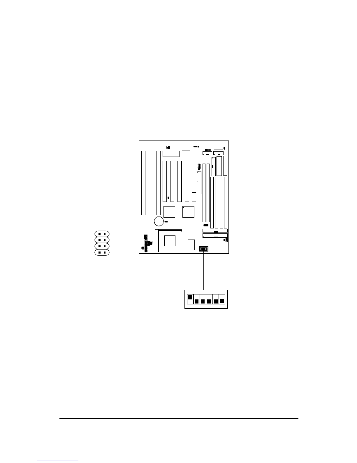
2.1-4 CPU Fan Power Connector: JFAN1/JFAN2/JSFAN/
JPFAN
JFAN1 connector supports CPU cooling fan with +12V. It supports both two
and three pin head connector. When connecting the wire to the connector,
always take note that the red wire is the positive and should be connected to
the +12V. While JFAN2, JSFAN, and JPFAN system cooling fan with
+12V. It supports three pin head connector. When connecting the wire to
the connector, always take note that the red wire is the positive and should
be connected to the +12V, the black wire is Ground and should be
connected to GND, the yellow is the speed sensor. If your mainboard has
LM78 on board, you need to use a specially designed fan with speed sensor
to take advantage of LM78’s CPU fan control function.
Note: 1. JFAN2/JSFAN/JPFAN is used for CPU Cooling Fan Speed
Connectors.
(Reserved for LM78 System Hardware Monitor Option.)
2. Always consult vendor for proper CPU cooling fan.
2-9
JF AN1
+12VGND GND
JF AN2
SPEED
+12V
GND
SPEED
+12V
GND
JPFAN
SPEED
+12V
GND
JSFAN
JFAN2: CPU FAN
JPFAN: POWER FAN
JSFAN: CHASSIS FAN
CHAPTER 2 HARDWARE INSTALLATION
2.2 PCI and ISA Slots
There are 5 PCI slots and 3 ISA slots. All PCI slots can be used as master.
But since the 1st and 5th PCI slots share the same bus master signal, only
one of these slots can be used as a master at a time; which means that if a
bus master card is installed in PCI slot 1, PCI Slot 5 can only accomodate a
slave card, and vice versa.
2-10
Note: 1 . You can only use a 3.3 V PCI Card, if the power supply you’re
using is an A TX power supply w/ 3.3V.
2. PCI Slot 1 to PCI Slot 5 IDSEL is AD_24(Device Num = 0DM) to
AD_28(Device Num = 11H) respectively.
ISA Slots
PCI Slots
PCI SLOT 1 (AD_24)
PCI SLOT 2 (AD_25)
PCI SLOT 3 (AD_26)
PCI SLOT 4 (AD_27)
PCI SLOT 5 (AD_28)
CHAPTER 2 HARDWARE INSTALLATION
SIMM4(Bank 4.5)
SIMM3(Bank 4.5)
SIMM2(Bank 2.3)
SIMM1(Bank 2.3)
2-11
DIMM1(Bank 2.3)
DIMM2 (Bank 0.1)
2.3 Memory Installation
2.3-1 Memory Bank Configuration
The mainboard provides four 72-pin SIMMs (Single In-Line Memory Module)
and two 168-pin DIMM(Double In-Line Memory) sockets. It supports six
memory banks for a maximum of 256MB memory . Each bank supports up to
64MB memory. Y ou can use SIMM from 4MB, 8MB, 16MB, 32MB, 64MB to
128MB, and DIMM from 8MB, 16MB, 32MB, 64MB to 128MB.
CHAPTER 2 HARDWARE INSTALLATION
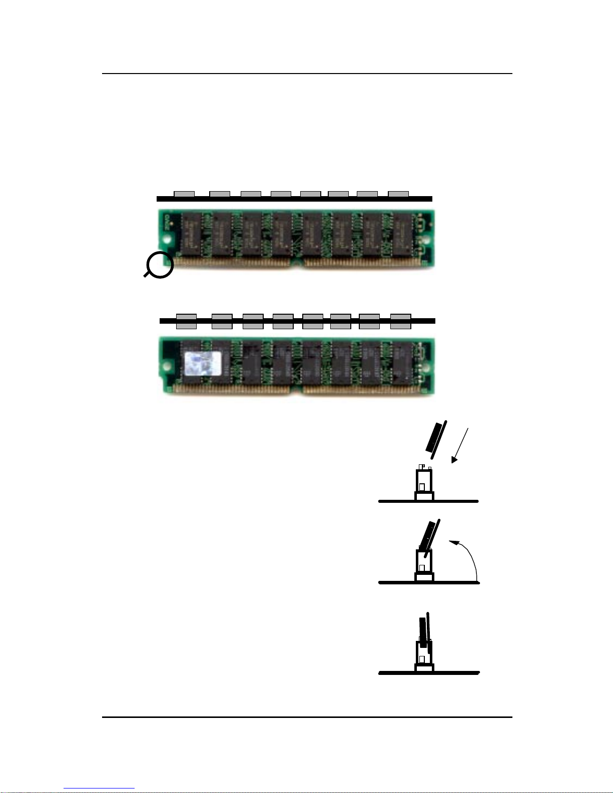
2.3-2 Memory Installation Procedures:
1. The SIMM slot has a “Plastic Safety
Tab” and the SIMM memory module
has a “Notched End”, so the SIMM
memory module can only fit in one
direction.
2. Insert the SIMM memory modules into
the socket at 45-degree angle, then
push into a vertical position so that it
will snap into place.
3. The Mounting Holes and Metal Clips
should fit over the edge and hold the
SIMM memory modules in place.
A. How to install SIMM Module
Single Sided SIMM
Double Sided SIMM
Notched
End
2-12
CHAPTER 2 HARDWARE INSTALLATION
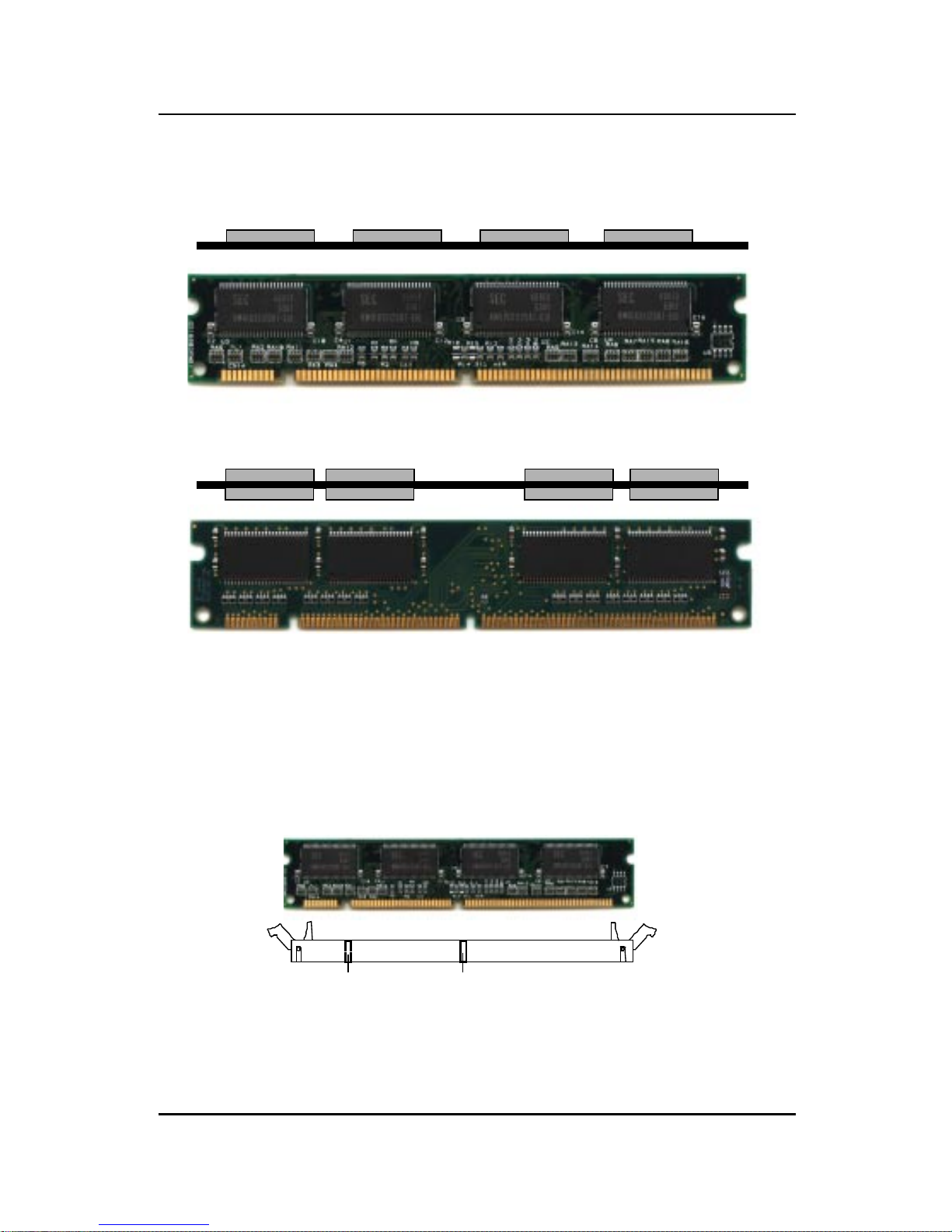
B. How to install DIMM Module
1. The DIMM slot has two keys marked “VOLT and DRAM” , so the
DIMM memory module can only fit in one direction.
2. Insert the DIMM memory module vertically into the DIMM slot.
Then, push it in.
3. Close the plastic clip at the side of the DIMM slot.
Single Sided DIMM
Double Sided DIMM
2-13
DRAM VOL T

CHAPTER 2 HARDWARE INSTALLATION
2-14
B.1 DIMM Power V oltage Selector: JV1
5V
3.3V
SIMM Power Level : 5 V olts
DIMM Power Level : 3.3V or 5V
NOTE: DIMM and SIMM cannot be used at the same time. Only
one kind can be used at a time. If you want to use both of
them at the same time, you must use 5V DIMM.
+3V
+3V
+5V
+5V
JV1
+3V
JV1
DIMM Voltage
+5V

CHAPTER 2 HARDWARE INSTALLATION
2-15
1. Make sure that the SIMM banks are using the same type and equal size
density memory.
2 . T o operate properly , at least two 72-pin SIMM module must be installed in
the same bank or one 168-pin DIMM module must be installed. The
system cannot operate with only one 72-pin SIMM module.
3. This mainboard supports Table Free memory , so memory can be installed
on (SIMM1 + SIMM2),(SIMM3 + SIMM4), (DIMM1), or (DIMM 2), in
any order .
4. If you use DIMM with 64Mbit SDRAM, then Bank2.3
(SIMM1+SIMM2) can not be use.
5 . DIMM and SIMM cannot be used at the same time. Only one kind can be
used at a time. If you want to use both of them you must use a 5V
DIMM.
2.3-3 Memory Population Rules
CHAPTER 2 HARDWARE INSTALLATION
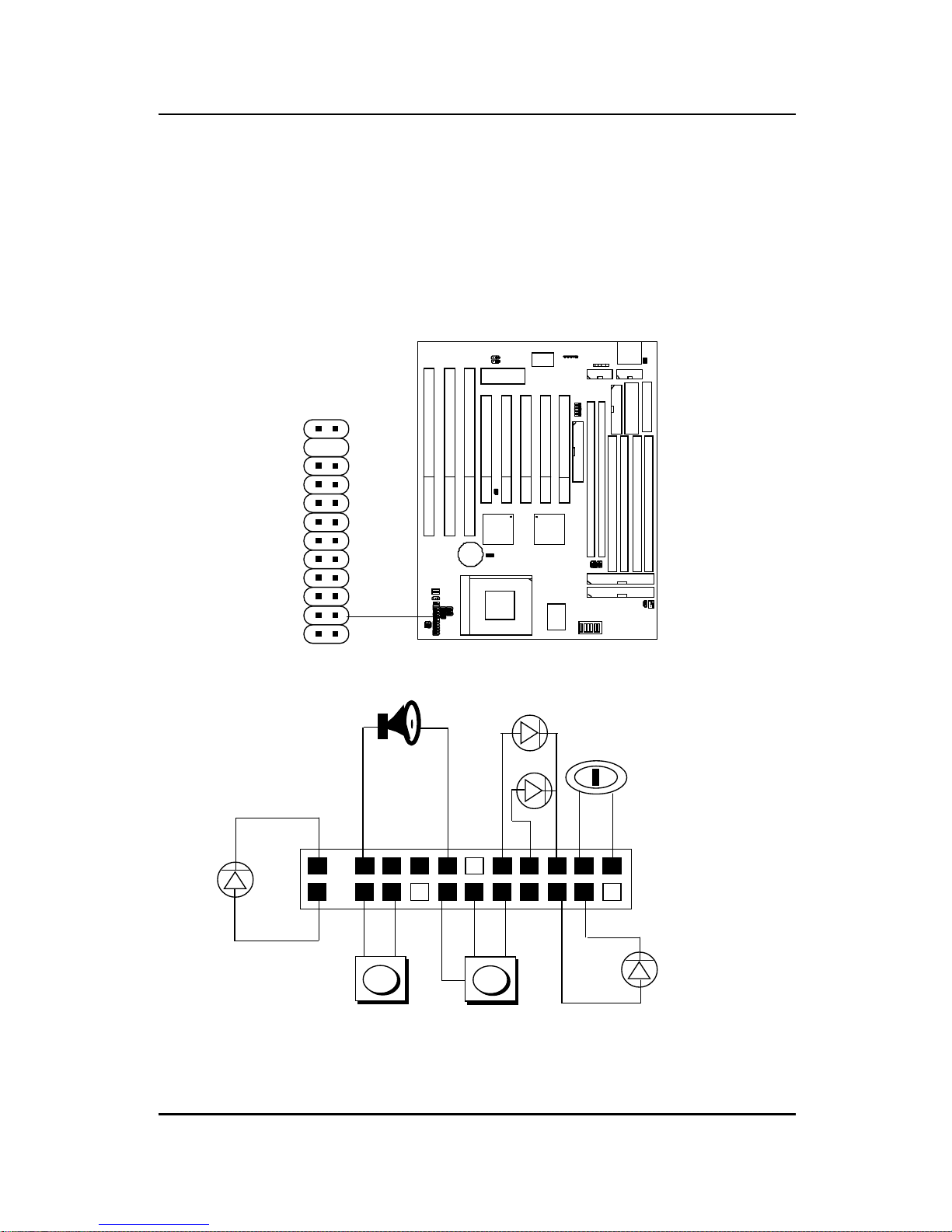
2.4 Case Connector: JFP1
The Turbo LED, Turbo Switch, Hardware Reset, Key Lock, Power LED,
Power Saving LED, Sleep Switch, Speaker and HDD LED are all grouped in
JFP1 connector block for easy installation.
1
x
x
1122
21
Speaker
Power LED
Keylock
Turbo LED
Reset Switch
HDD LED
10
20
+
+
+
Turbo Switch
L
H
+
Power
Saving
LED
Figure 2.1
2-16
1
JFP1
10
21

CHAPTER 2 HARDWARE INSTALLATION
2.4-1 Turbo LED
This mainboard is always on Turbo speed. Connecting a Turbo LED will just
lit the LED. (See Figure 2.1)
2.4-2 Hardware Reset
Reset switch are used to reboot the system rather than turning the power
ON/OFF . A void rebooting the system when the HDD LED is lit. You can
connect the Reset switch from the system case to this pin. (See Figure 2.1)
2.4-3 Keylock
Keylock allows you to disable the keyboard for security purposes. You can
connect the keylock to this pin. (See Figure 2.1)
2.4-4 Power LED
The Power LED is always lit while the system power is on. You can connect
the Power LED from the system case to this pin. (See Figure 2.1)
2.4-5 Turbo Switch
This mainboard is always on Turbo Speed. So the Turbo Switch is nonfunctional. (See Figure 2.1)
2.4-6 Speaker
Speaker from the system case are connected to this pin. (See Figure 2.1)
2.4-7 HDD LED
HDD LED shows the activity of a hard disk drive. Avoid turning the power
off while the HDD led is lit. You can connect the HDD LED from the system
case to this pin. (See Figure 2.1).
2-17
CHAPTER 2 HARDWARE INSTALLATION
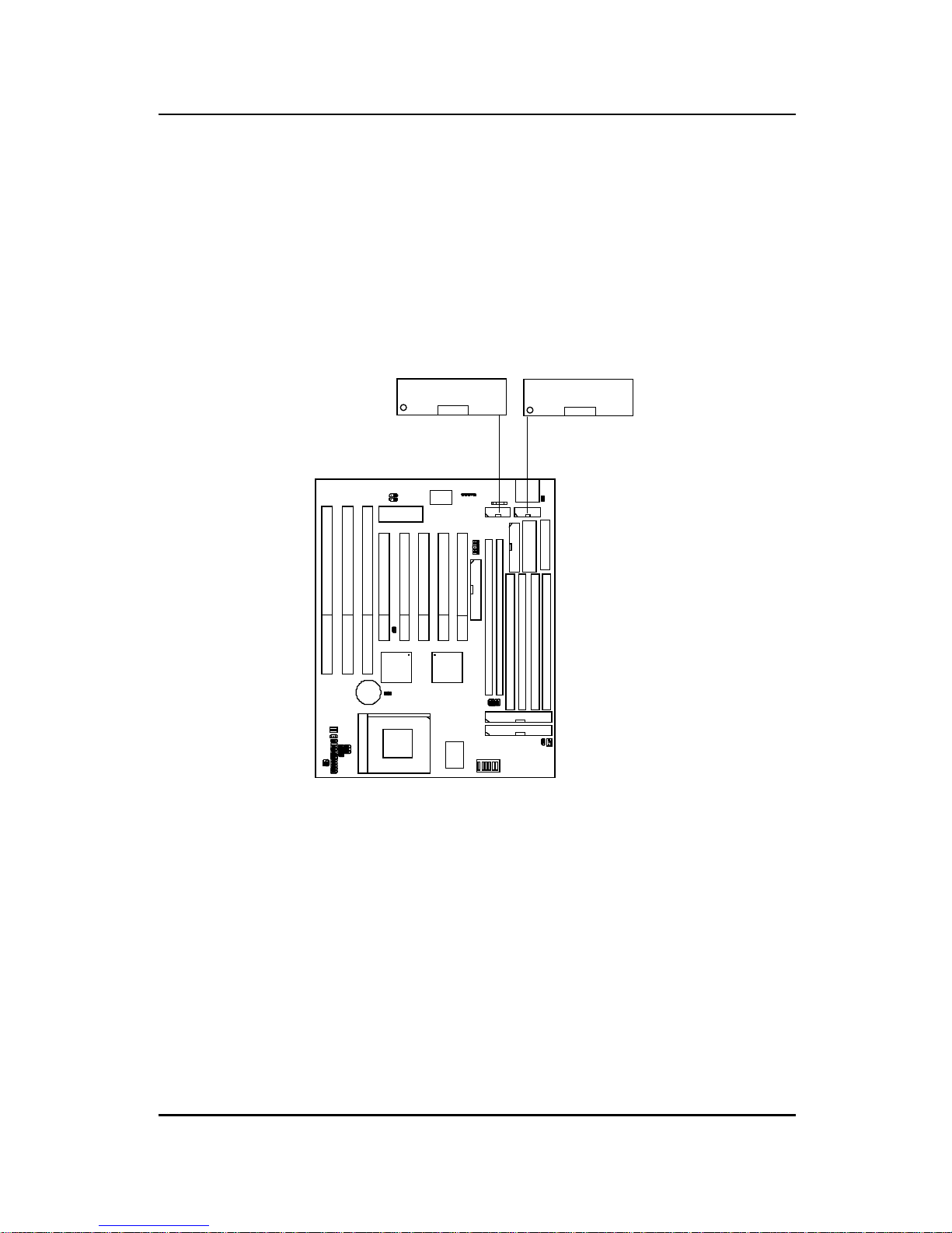
2.5 Serial Port Connectors: COM A & COM B
The mainboard has two serial ports COM A and COM B. These two ports
are 16550A fully compatible high speed communication ports that send/
receive 16 bytes FIFOs. You can attach a mouse or a modem cable directly
into these connectors.
COM B
2-18
COM A
1
1
CHAPTER 2 HARDWARE INSTALLATION
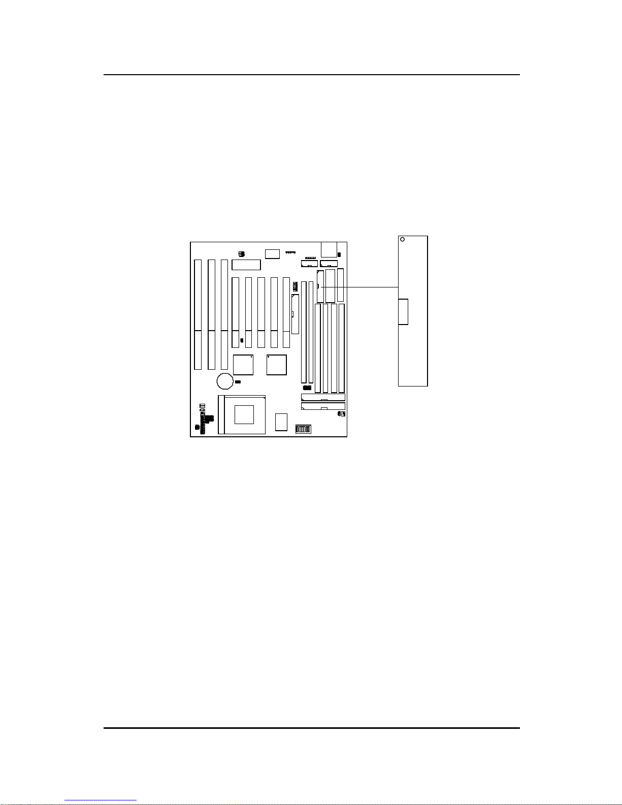
2.6 Parallel Port Connector: LPT
The mainboard provides a connector for LPT. A parallel port is a standard
printer port that also supports Enhanced Parallel Port(EPP) and Extended
capabilities Parallel Port(ECP).
LPT
2-19
1
CHAPTER 2 HARDWARE INSTALLATION
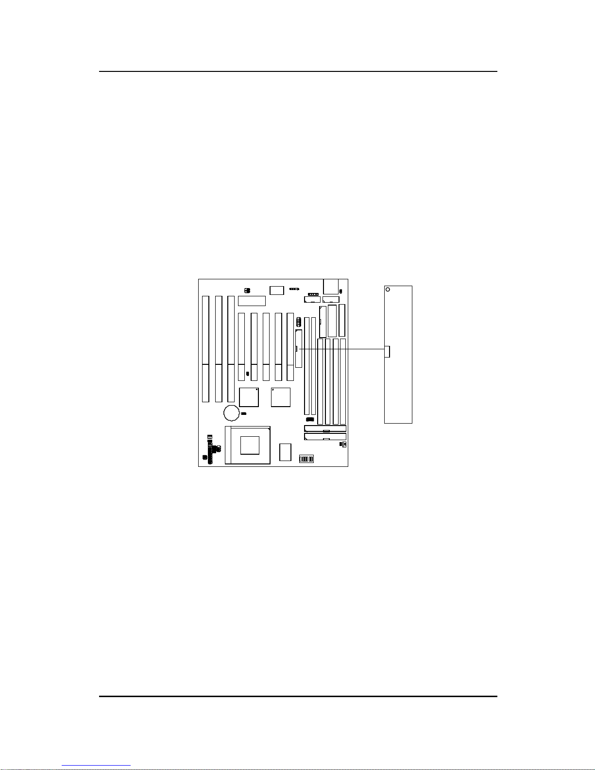
2.7 Floppy Disk Connector: FDC
The mainboard also provides a standard floppy disk connector , FDC that
supports 360K, 720K, 1.2M, 1.44M and 2.88M floppy disk types. You can
attach a floppy disk cable directly to this connector.
FDC
1
2-20
CHAPTER 2 HARDWARE INSTALLATION
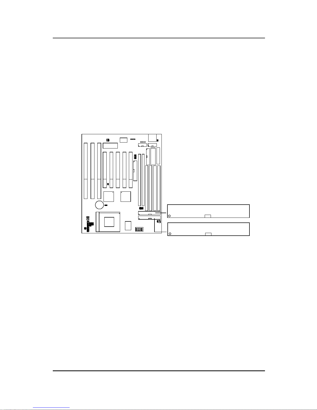
2.8 Hard Disk Connectors: IDE1 & IDE2
The mainboard has a 32-bit Enhanced PCI IDE Controller that provides for
two HDD connectors IDE1 (primary) and IDE2 (secondary). Y ou can
connect up to four hard disk drives, CD-ROM, 120MB Floppy (reserved for
future BIOS) and other devices to IDE1 and IDE2.
IDE1(primary IDE connector)
The first hard disk should always be connected to IDE1. IDE1 can
connect a Master and a Slave drive.
IDE2(secondary IDE connector)
IDE2 can connect a Master and a Slave drive.
2-21
Primary IDE Connector
Secondary IDE Connector
1
1
CHAPTER 2 HARDWARE INSTALLATION
2.9 Power Supply Connector: J9
J9 is a standard 12-pin AT® or PS/2® connector. Be sure to attach the
connectors with the two black wires at the center.
Power Connector
Pin Description Pin Description
1 Power Good 7 Ground
2 +5V DC 8 Ground
3 +12V DC 9 -5V DC
4 -12V DC 10 +5V DC
5 Ground 11 +5V DC
6 Ground 12 +5V DC
12
1
2-22
J9

CHAPTER 2 HARDWARE INSTALLATION
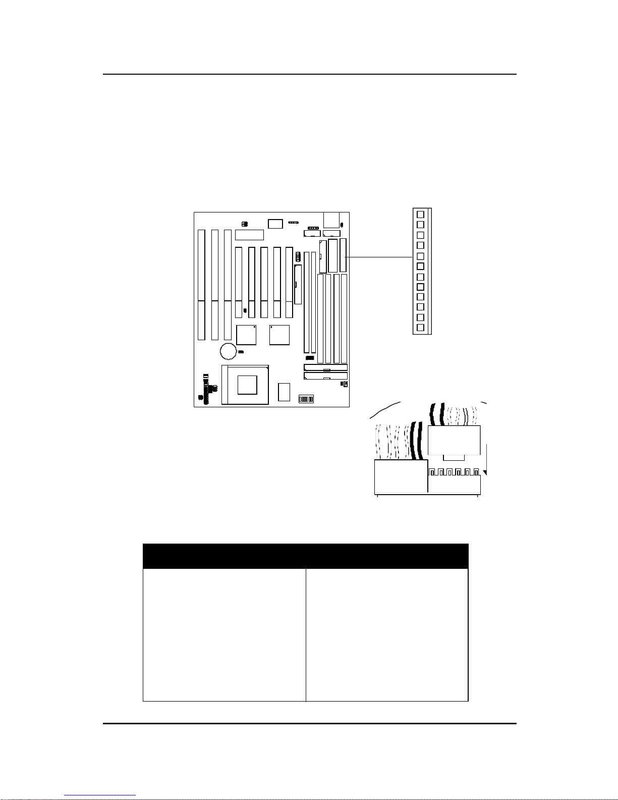
2.10 ATX 20-pin Power Connector: JWR1
This type of connector already supports the remote ON/OFF function. You
don’t need to connect the JRMC1. However, you need to connect the
Remote Power On/OFF switch (JRMS1 or JRMS2).
5V 5V -5V
5V5V
3.3V-12V
12V 5V_SB 3.3V3.3V
GND GND
GND
GND
GND
GND
GND
PW_OK
PS_ON
1
23
456
7
8
9
10
11
1213
14
15
16
1718
19
20
ATX Power Connector Pin Description
ATX
Power Connector
2-23
10
1
11
20
CHAPTER 2 HARDWARE INSTALLATION
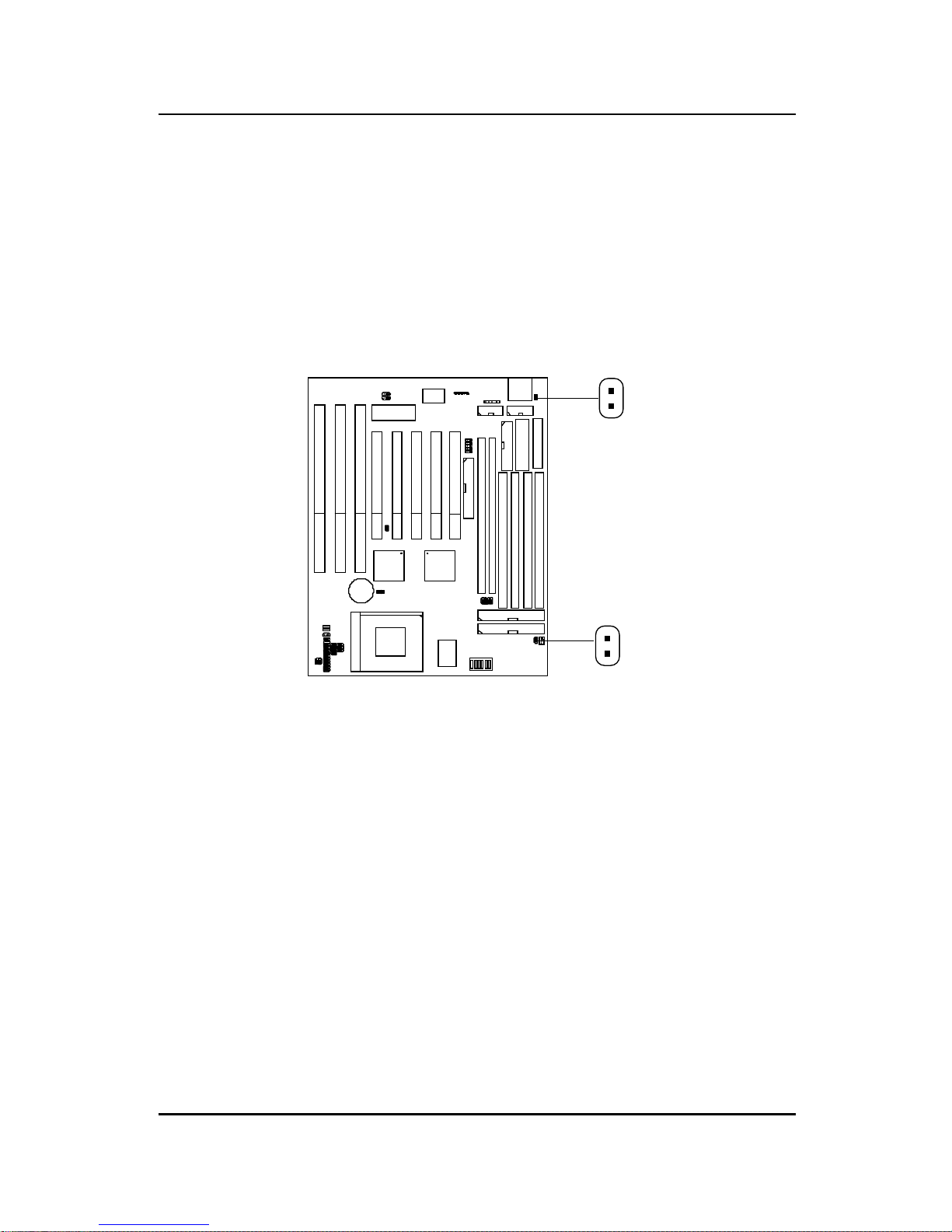
2.11 Remote Power On/Off Switch: JRMS1/JRMS2
Connect to a 2-pin push button switch to JRMS1 or JRMS2. Every time the
switch is shorted by pushing it once, the power supply will change its status
from OFF to ON and ON to OFF. This is used for A TX type power supply.
You can program this through BIOS. Refer to Soft-Off by PWR-BTTN in
BIOS.
JRMS1
2-24
JRMS2
 Loading...