

Page 1

MOTOTRBO
PROFESSIONAL DIGITAL TWO-WAY RADIO
™
DP4801 Ex, DP4401 Ex
Portable Radio User Guide
FEBRUARY 2024
©
2024 Motorola Solutions, Inc. All Rights Reserved.
*MN008329A01*
MN008329A01-AC
Page 2

MN008329A01-AC
Contents
Contents
Legal and Support............................................................................................................... 9
Intellectual Property and Regulatory Notices...........................................................................................9
Legal and Compliance Statements........................................................................................................ 10
Important Safety Information.......................................................................................................10
Warranty and Service Support...............................................................................................................10
Limited Warranty......................................................................................................................... 10
MOTOROLA SOLUTIONS COMMUNICATION PRODUCTS.......................................... 10
I. WHAT THIS WARRANTY COVERS AND FOR HOW LONG:...................................... 10
II. GENERAL PROVISIONS............................................................................................. 11
III. STATE LAW RIGHTS:................................................................................................. 11
IV. HOW TO GET WARRANTY SERVICE....................................................................... 11
V. WHAT THIS WARRANTY DOES NOT COVER........................................................... 11
VI. PATENT AND SOFTWARE PROVISIONS................................................................. 12
VII. GOVERNING LAW.................................................................................................... 12
VIII. For Australia Only..................................................................................................... 12
Chapter 1: Read Me First...................................................................................................13
1.1 Software Version..............................................................................................................................14
Chapter 2: Introduction......................................................................................................15
Chapter 3: Radio Care........................................................................................................16
Chapter 4: Getting Started.................................................................................................17
4.1 Charging the Battery........................................................................................................................ 17
4.2 Attaching the Battery........................................................................................................................17
4.3 Removing the Battery...................................................................................................................... 18
4.4 Attaching the Antenna......................................................................................................................18
4.5 Removing the Antenna.................................................................................................................... 18
4.6 Attaching the Belt Clip......................................................................................................................19
4.7 Removing the Belt Clip.................................................................................................................... 19
4.8 Attaching the Universal Connector Cover........................................................................................19
4.9 Removing the Universal Connector Cover.......................................................................................19
4.10 Turning the Radio On.....................................................................................................................19
4.11 Turning the Radio Off..................................................................................................................... 20
4.12 Adjusting the Volume..................................................................................................................... 20
Chapter 5: Radio Overview................................................................................................21
5.1 Keypad Overview.............................................................................................................................23
5.2 Programmable Buttons.................................................................................................................... 24
2
Page 3

MN008329A01-AC
Contents
5.3 Icons................................................................................................................................................ 27
5.3.1 Display Icons......................................................................................................................27
5.3.2 Advanced Menu Icons........................................................................................................29
5.3.3 Call Icons........................................................................................................................... 29
5.3.4 Job Tickets Icons................................................................................................................30
5.3.5 Mini Notice Icons................................................................................................................31
5.3.6 Sent Items Icons................................................................................................................ 31
5.4 LED Indications................................................................................................................................31
Chapter 6: System Overview.............................................................................................33
6.1 Capacity Max................................................................................................................................... 33
6.2 Other Systems................................................................................................................................. 33
6.2.1 Conventional Analog and Digital Modes............................................................................ 33
6.2.2 IP Site Connect.................................................................................................................. 33
6.2.3 Capacity Plus..................................................................................................................... 34
Chapter 7: Registration......................................................................................................35
Chapter 8: Zone and Channel Selections........................................................................ 36
8.1 Selecting Zones............................................................................................................................... 36
8.2 Selecting Zones Using Alias Search................................................................................................36
8.3 Selecting Channels.......................................................................................................................... 37
8.4 Selecting Channels Using Direct Channel Dial................................................................................37
Chapter 9: Site Overview...................................................................................................38
9.1 Site Restriction.................................................................................................................................38
9.2 Site Trunking....................................................................................................................................38
9.3 Turning the Site Lock On................................................................................................................. 39
9.4 Turning the Site Lock Off................................................................................................................. 39
9.5 Enabling the Manual Site Search.....................................................................................................39
9.6 Accessing Neighbor Sites List......................................................................................................... 40
Chapter 10: Types of Radio Calls..................................................................................... 41
10.1 Making Calls on the Radio............................................................................................................. 42
10.2 Making Calls with Contact List....................................................................................................... 43
10.3 Making Calls with Manual Dial....................................................................................................... 43
10.4 Making Calls with Programmable Number Keys............................................................................44
10.5 Receiving and Responding to Calls on the Radio..........................................................................44
10.6 Accepting or Declining Private Calls.............................................................................................. 44
Accepting Private Calls............................................................................................................... 45
Declining Private Calls................................................................................................................ 45
Chapter 11: Phone Calls....................................................................................................46
11.1 Making Phone Calls....................................................................................................................... 46
3
Page 4

MN008329A01-AC
Contents
11.2 Making Phone Calls with Contact List............................................................................................ 46
11.3 Making Phone Calls with Manual Dial............................................................................................ 47
11.4 Dual Tone Multi Frequency.............................................................................................................47
11.4.1 Initiating the DTMF Tone.................................................................................................. 47
11.5 Receiving and Responding to Phone Calls.................................................................................... 48
Chapter 12: Call Preemption ............................................................................................ 49
Chapter 13: Voice Interrupt............................................................................................... 50
13.1 Enabling the Voice Interrupt...........................................................................................................50
Chapter 14: Initiating Transmit Interrupt..........................................................................51
Chapter 15: Advanced Features....................................................................................... 52
15.1 Analog Message Encode............................................................................................................... 52
15.1.1 Sending MDC Encode Messages to Dispatchers............................................................ 52
15.1.2 Sending 5-Tone Encode Messages to Contacts.............................................................. 52
15.2 Analog Status Update.................................................................................................................... 53
15.2.1 Sending Status Updates to Predefined Contacts.............................................................53
15.2.2 Viewing 5-Tone Status Details..........................................................................................53
15.2.3 Editing 5-Tone Status Details........................................................................................... 54
15.3 Auto-Range Transponder System..................................................................................................54
15.4 Call Alert Operation........................................................................................................................54
15.4.1 Making Call Alerts............................................................................................................ 55
15.4.2 Responding to Call Alerts.................................................................................................55
15.5 Call Indicator Settings.................................................................................................................... 55
15.5.1 Activating or Deactivating Call Ringers............................................................................ 56
Activating Call Ringers..................................................................................................... 56
Deactivating Call Ringers................................................................................................. 56
15.5.2 Assigning Ring Styles...................................................................................................... 57
15.5.3 Escalating Alarm Tone Volume........................................................................................ 57
15.6 Call Log Features...........................................................................................................................57
15.6.1 Viewing Recent Calls....................................................................................................... 57
15.6.2 Storing Aliases or IDs from the Call List...........................................................................58
15.6.3 Deleting Calls from the Call List....................................................................................... 58
15.6.4 Viewing Details from the Call List.....................................................................................58
15.7 Call Queue..................................................................................................................................... 58
15.7.1 Receiving Call Queues.....................................................................................................59
15.8 Contacts Settings...........................................................................................................................59
15.8.1 Adding New Contacts.......................................................................................................59
15.8.2 Setting Default Contacts.................................................................................................. 60
15.8.3 Assigning Entries to Programmable Number Keys.......................................................... 60
4
Page 5

MN008329A01-AC
Contents
15.8.4 Removing Associations Between Entries and Programmable Number Keys.................. 60
15.9 Dynamic Caller Alias......................................................................................................................61
15.9.1 Editing the Caller Alias..................................................................................................... 61
15.9.2 Viewing the Caller Aliases List......................................................................................... 61
15.9.3 Initiating Private Calls From the Caller Aliases List..........................................................62
15.10 Dynamic Group Number Assignment.......................................................................................... 62
15.10.1 Making DGNA Calls....................................................................................................... 62
15.10.2 Making Non-DGNA Calls............................................................................................... 63
15.10.3 Receiving and Responding to DGNA Calls....................................................................63
15.11 Emergency Operation.................................................................................................................. 63
15.11.1 Sending Emergency Alarms........................................................................................... 64
15.11.2 Sending Emergency Alarms with Call............................................................................ 65
15.11.3 Sending Emergency Alarms with Voice to Follow.......................................................... 65
15.11.4 Responding to Emergency Alarms................................................................................. 65
15.11.5 Responding to Emergency Alarms with Call.................................................................. 66
15.11.6 Reinitiating the Emergency Mode...................................................................................67
15.11.7 Exiting the Emergency Mode..........................................................................................67
15.12 Fall Alert.......................................................................................................................................67
15.12.1 Turning the Fall Alert Feature On...................................................................................68
15.12.2 Turning the Fall Alert Feature Off...................................................................................68
15.13 Entering the Front Panel Programming....................................................................................... 68
15.14 Home Channel Reminder............................................................................................................ 68
15.14.1 Muting the Home Channel Reminder.............................................................................69
15.14.2 Setting New Home Channels......................................................................................... 69
15.15 Job Tickets...................................................................................................................................69
15.15.1 Accessing the Job Tickets Folder...................................................................................70
15.15.2 Logging In the Remote Server....................................................................................... 70
15.15.3 Creating Job Tickets.......................................................................................................70
15.15.4 Sending Job Tickets Using Job Tickets Templates........................................................ 70
15.15.5 Responding to Job Tickets.............................................................................................71
15.15.6 Deleting Job Tickets.......................................................................................................71
15.16 Lone Worker.................................................................................................................................72
15.17 Monitor Feature............................................................................................................................72
15.17.1 Monitoring Channels...................................................................................................... 72
15.17.2 Permanent Monitor.........................................................................................................73
15.17.2.1 Setting the Permanent Monitor.........................................................................73
15.18 Priority Monitor.............................................................................................................................73
15.18.1 Receive Group List.........................................................................................................74
15.19 Remote Monitor........................................................................................................................... 74
5
Page 6

MN008329A01-AC
Contents
15.19.1 Initiating the Remote Monitor......................................................................................... 75
15.20 Mute Mode................................................................................................................................... 75
15.20.1 Turning the Mute Mode On............................................................................................ 76
15.20.2 Setting the Mute Mode Timer.........................................................................................76
15.20.3 Exiting the Mute Mode................................................................................................... 76
15.21 Notification List.............................................................................................................................77
15.21.1 Accessing the Notification List....................................................................................... 77
15.22 Over-the-Air Programming...........................................................................................................77
15.23 Scan.............................................................................................................................................78
15.23.1 Turning the Scan On...................................................................................................... 79
15.23.2 Turning the Scan Off...................................................................................................... 79
15.23.3 Scan Talkback................................................................................................................ 79
15.23.4 Nuisance Channels........................................................................................................ 80
15.23.4.1 Deleting Nuisance Channels............................................................................ 80
15.23.4.2 Restoring Nuisance Channels..........................................................................80
15.23.5 Vote Scan.......................................................................................................................80
15.23.6 Scan Lists.......................................................................................................................81
15.23.6.1 Editing the Scan List.........................................................................................81
15.23.6.2 Editing Priority for the Scan List....................................................................... 81
15.23.6.3 Viewing the Scan List....................................................................................... 82
15.23.6.4 Adding New Entries to the Scan List................................................................ 82
15.23.6.5 Deleting Entries from the Scan List.................................................................. 82
15.23.7 Flexible Receive List ..................................................................................................... 83
15.23.7.1 Turning the Flexible Receive List On................................................................83
15.23.7.2 Turning the Flexible Receive List Off................................................................83
15.23.7.3 Adding New Entries to the Flexible Receive List..............................................83
15.23.7.4 Deleting Entries from the Flexible Receive List................................................83
15.23.8 Multi-Talkgroup Affiliation............................................................................................... 84
15.23.8.1 Adding the Talkgroup Affiliation........................................................................ 84
15.23.8.2 Removing the Talkgroup Affiliation................................................................... 84
15.24 Priority Call...................................................................................................................................84
15.24.1 Switching the Priority Call Level.....................................................................................85
15.25 Radio Check................................................................................................................................ 85
15.25.1 Sending Radio Checks...................................................................................................86
15.26 Radio Kill......................................................................................................................................86
15.27 Received Signal Strength Indicator..............................................................................................86
15.27.1 Viewing RSSI Values......................................................................................................86
15.28 Response Inhibit.......................................................................................................................... 87
15.28.1 Setting the Response Inhibit.......................................................................................... 87
6
Page 7

MN008329A01-AC
Contents
15.29 Rental Timer.................................................................................................................................87
15.29.1 Accessing Rental Timer Information.............................................................................. 88
15.29.2 Rental Expiry Reminder................................................................................................. 88
15.29.3 Extending the Rental Period.......................................................................................... 88
15.30 Security........................................................................................................................................ 88
15.30.1 Disabling Radios............................................................................................................ 89
15.30.2 Enabling Radios............................................................................................................. 90
15.31 Service and Support.................................................................................................................... 90
15.31.1 Accessing Notifications.................................................................................................. 90
15.31.2 Accessing Service and Support..................................................................................... 91
15.31.3 Viewing Service Contact................................................................................................ 92
15.32 Stun or Revive............................................................................................................................. 92
15.32.1 Stunning Radios.............................................................................................................93
15.32.2 Reviving Radios............................................................................................................. 93
15.33 Status Message........................................................................................................................... 94
15.33.1 Viewing Status Messages.............................................................................................. 94
15.33.2 Sending Status Messages............................................................................................. 94
15.33.3 Responding to Status Messages................................................................................... 95
15.33.4 Deleting Status Messages............................................................................................. 95
15.34 Text Messaging............................................................................................................................ 95
15.34.1 Viewing Text Messages..................................................................................................96
15.34.2 Composing Text Messages............................................................................................ 96
15.34.3 Sending Text Messages................................................................................................. 96
15.34.4 Responding to Text Messages....................................................................................... 97
15.34.5 Forwarding Text Messages............................................................................................ 98
15.34.6 Deleting Text Messages................................................................................................. 99
15.34.7 Setting Text Message Alert Tones..................................................................................99
Chapter 16: Utilities..........................................................................................................100
16.1 Talkaround................................................................................................................................... 100
16.1.1 Toggling Between Repeater and Talkaround Mode....................................................... 100
16.2 Setting Radio Tones and Alerts....................................................................................................100
16.3 Setting Power Levels................................................................................................................... 101
16.4 Adjusting Display Settings........................................................................................................... 101
16.5 Setting Squelch Levels................................................................................................................ 101
16.6 Keypad Lock Options...................................................................................................................102
16.6.1 Locking or Unlocking the Keypad...................................................................................102
16.7 Setting Languages....................................................................................................................... 102
16.8 Setting LED Indicators................................................................................................................. 103
16.9 Password Lock.............................................................................................................................103
7
Page 8

MN008329A01-AC
Contents
16.9.1 Accessing Radios with Password.................................................................................. 103
16.9.2 Unlocking Radios in Locked State................................................................................. 104
16.9.3 Setting the Password Lock.............................................................................................104
16.9.4 Changing Passwords..................................................................................................... 104
16.10 Voice Announcement.................................................................................................................105
16.10.1 Setting the Voice Announcement.................................................................................105
16.11 Text-to-Speech........................................................................................................................... 105
16.11.1 Setting the Text-to-Speech........................................................................................... 106
16.12 Setting the Microphone Automatic Gain Control........................................................................106
16.13 Setting the Microphone Distortion..............................................................................................106
16.14 Setting the Text Entry.................................................................................................................107
16.15 Privacy....................................................................................................................................... 107
16.15.1 Setting Privacy............................................................................................................. 108
16.16 Voice Operating Transmission................................................................................................... 108
16.16.1 Setting the Voice Operating Transmission................................................................... 109
16.17 Setting the Audio Ambience.......................................................................................................109
16.18 Setting the Audio Profiles...........................................................................................................109
16.19 Setting the Acoustic Feedback Suppressor............................................................................... 110
16.20 Setting the Global Navigation Satellite System..........................................................................110
16.21 Setting the Automatic Call Forwarding.......................................................................................110
16.22 Setting the Option Board............................................................................................................ 111
16.23 Setting the Intelligent Audio........................................................................................................111
16.24 Setting the Trill Enhancement.....................................................................................................111
16.25 Accessing the Radio Information................................................................................................112
16.26 Identifying the Cable Type..........................................................................................................112
16.27 Switching Audio Route between Internal Radio Speaker and Wired Accessory........................112
8
Page 9

MN008329A01-AC
Legal and Support
Legal and Support
Intellectual Property and Regulatory Notices
Copyrights
The Motorola Solutions products described in this document may include copyrighted Motorola Solutions
computer programs. Laws in the United States and other countries preserve for Motorola Solutions
certain exclusive rights for copyrighted computer programs. Accordingly, any copyrighted Motorola Solutions
computer programs contained in the Motorola Solutions products described in this document may not be
copied or reproduced in any manner without the express written permission of Motorola Solutions.
No part of this document may be reproduced, transmitted, stored in a retrieval system, or translated into
any language or computer language, in any form or by any means, without the prior written permission of
Motorola Solutions, Inc.
Trademarks
MOTOROLA, MOTO, MOTOROLA SOLUTIONS, and the Stylized M Logo are trademarks or registered
trademarks of Motorola Trademark Holdings, LLC and are used under license. All other trademarks are the
property of their respective owners.
License Rights
The purchase of Motorola Solutions products shall not be deemed to grant either directly or by implication,
estoppel or otherwise, any license under the copyrights, patents or patent applications of Motorola Solutions,
except for the normal nonexclusive, royalty-free license to use that arises by operation of law in the sale of a
product.
Open Source Content
This product may contain Open Source software used under license. Refer to the product installation media
for full Open Source Legal Notices and Attribution content.
European Union (EU) and United Kingdom (UK) Waste of Electrical and Electronic
Equipment (WEEE) Directive
The European Union's WEEE directive and the UK's WEEE regulation require that products sold into
EU countries and the UK must have the crossed-out wheelie bin label on the product (or the package in some
cases). As defined by the WEEE directive, this crossed-out wheelie bin label means that customers and end
users in EU and UK countries should not dispose of electronic and electrical equipment or accessories in
household waste.
Customers or end users in EU and UK countries should contact their local equipment supplier representative
or service center for information about the waste collection system in their country.
Disclaimer
Please note that certain features, facilities, and capabilities described in this document may not be applicable
to or licensed for use on a specific system, or may be dependent upon the characteristics of a specific mobile
subscriber unit or configuration of certain parameters. Please refer to your Motorola Solutions contact for
further information.
9
Page 10
MN008329A01-AC
Legal and Support
©
2024 Motorola Solutions, Inc. All Rights Reserved
Legal and Compliance Statements
Important Safety Information
RF Energy Exposure and Product Safety Guide for Portable Two-Way Radios
CAUTION:
This radio is restricted to Occupational use only. Before using the radio, read the RF Energy
Exposure and Product Safety Guide that comes with the radio. This guide contains operating
instructions for safe usage, RF energy awareness, and control for compliance with applicable standards
and regulations.
Warranty and Service Support
Limited Warranty
MOTOROLA SOLUTIONS COMMUNICATION PRODUCTS
I. WHAT THIS WARRANTY COVERS AND FOR HOW LONG:
Motorola Solutions, Inc. ("Motorola Solutions") warrants the Motorola Solutions manufactured Communication
Products listed below ("Product") against defects in material and workmanship under normal use and service
for a period of time from the date of purchase as scheduled below:
Portable Radios Two (2) Years
Product Accessories (Including Batteries and
Chargers)
Motorola Solutions, at its option, will at no charge either repair the Product (with new or reconditioned parts),
replace it (with a new or reconditioned Product), or refund the purchase price of the Product during the
warranty period provided it is returned in accordance with the terms of this warranty. Replaced parts or
boards are warranted for the balance of the original applicable warranty period. All replaced parts of Product
shall become the property of Motorola Solutions.
This express limited warranty is extended by Motorola Solutions to the original end user purchaser only
and is not assignable or transferable to any other party. This is the complete warranty for the Product
manufactured by Motorola Solutions. Motorola Solutions assumes no obligations or liability for additions or
modifications to this warranty unless made in writing and signed by an officer of Motorola Solutions.
Unless made in a separate agreement between Motorola Solutions and the original end user purchaser,
Motorola Solutions does not warrant the installation, maintenance or service of the Product.
Motorola Solutions cannot be responsible in any way for any ancillary equipment not furnished by Motorola
Solutions which is attached to or used in connection with the Product, or for operation of the Product with any
ancillary equipment, and all such equipment is expressly excluded from this warranty. Because each system
which may use the Product is unique, Motorola Solutions disclaims liability for range, coverage, or operation
of the system as a whole under this warranty.
One (1) Year
10
Page 11

MN008329A01-AC
Legal and Support
II. GENERAL PROVISIONS
This warranty sets forth the full extent of Motorola Solutions responsibilities regarding the Product. Repair,
replacement or refund of the purchase price, at Motorola Solutions option, is the exclusive remedy. THIS
WARRANTY IS GIVEN IN LIEU OF ALL OTHER EXPRESS WARRANTIES. IMPLIED WARRANTIES,
INCLUDING WITHOUT LIMITATION, IMPLIED WARRANTIES OF MERCHANTABILITY AND FITNESS FOR
A PARTICULAR PURPOSE, ARE LIMITED TO THE DURATION OF THIS LIMITED WARRANTY. IN NO
EVENT SHALL MOTOROLA SOLUTIONS BE LIABLE FOR DAMAGES IN EXCESS OF THE PURCHASE
PRICE OF THE PRODUCT, FOR ANY LOSS OF USE, LOSS OF TIME, INCONVENIENCE, COMMERCIAL
LOSS, LOST PROFITS OR SAVINGS OR OTHER INCIDENTAL, SPECIAL OR CONSEQUENTIAL
DAMAGES ARISING OUT OF THE USE OR INABILITY TO USE SUCH PRODUCT, TO THE FULL EXTENT
SUCH MAY BE DISCLAIMED BY LAW.
III. STATE LAW RIGHTS:
SOME STATES DO NOT ALLOW THE EXCLUSION OR LIMITATION OF INCIDENTAL OR
CONSEQUENTIAL DAMAGES OR LIMITATION ON HOW LONG AN IMPLIED WARRANTY LASTS, SO
THE ABOVE LIMITATION OR EXCLUSIONS MAY NOT APPLY.
This warranty gives specific legal rights, and there may be other rights which may vary from state to state.
IV. HOW TO GET WARRANTY SERVICE
You must provide proof of purchase (bearing the date of purchase and Product item serial number) in order to
receive warranty service and, also, deliver or send the Product item, transportation and insurance prepaid, to
an authorized warranty service location. Warranty service will be provided by Motorola Solutions through one
of its authorized warranty service locations. If you first contact the company which sold you the Product (for
example, dealer or communication service provider), it can facilitate your obtaining warranty service. You can
also call Motorola Solutions at 1-800-927-2744.
V. WHAT THIS WARRANTY DOES NOT COVER
1. Defects or damage resulting from use of the Product in other than its normal and customary manner.
2. Defects or damage from misuse, accident, water, or neglect.
3. Defects or damage from improper testing, operation, maintenance, installation, alteration, modification, or
adjustment.
4. Breakage or damage to antennas unless caused directly by defects in material workmanship.
5. A Product subjected to unauthorized Product modifications, disassembles or repairs (including, without
limitation, the addition to the Product of non-Motorola Solutions supplied equipment) which adversely
affect performance of the Product or interfere with Motorola Solutions normal warranty inspection and
testing of the Product to verify any warranty claim.
6. Product which has had the serial number removed or made illegible.
7. Rechargeable batteries if any of the seals on the battery enclosure of cells are broken or show evidence
of tampering.
8. Rechargeable batteries if the damage or defect is caused by charging or using the battery in equipment
or service other than the Product for which it is specified.
9. Freight costs to the repair depot.
10. A Product which, due to illegal or unauthorized alteration of the software/firmware in the Product, does
not function in accordance with Motorola Solutions published specifications or the FCC certification
labeling in effect for the Product at the time the Product was initially distributed from Motorola Solutions.
11
Page 12

MN008329A01-AC
Legal and Support
11. Scratches or other cosmetic damage to Product surfaces that does not affect the operation of the
Product.
12. Normal and customary wear and tear.
VI. PATENT AND SOFTWARE PROVISIONS
Motorola Solutions will defend, at its own expense, any suit brought against the end user purchaser to the
extent that it is based on a claim that the Product or parts infringe a United States patent, and Motorola
Solutions will pay those costs and damages finally awarded against the end user purchaser in any such suit
which are attributable to any such claim, but such defense and payments are conditioned on the following:
1. Motorola Solutions will be notified promptly in writing by such purchaser of any notice of such claim,
2. Motorola Solutions will have sole control of the defense of such suit and all negotiations for its settlement
or compromise, and
3. Should the Product or parts become, or in Motorola Solutions opinion be likely to become, the subject of
a claim of infringement of a United States patent, that such purchaser will permit Motorola Solutions, at its
option and expense, either to procure for such purchaser the right to continue using the Product or parts
or to replace or modify the same so that it becomes non-infringing or to grant such purchaser a credit for
the Product or parts as depreciated and accept its return. The depreciation will be an equal amount per
year over the lifetime of the Product or parts as established by Motorola Solutions.
Motorola Solutions will have no liability with respect to any claim of patent infringement which is based
upon the combination of the Product or parts furnished hereunder with software, apparatus or devices
not furnished by Motorola Solutions, nor will Motorola Solutions have any liability for the use of ancillary
equipment or software not furnished by Motorola Solutions which is attached to or used in connection with the
Product. The foregoing states the entire liability of Motorola Solutions with respect to infringement of patents
by the Product or any parts thereof.
Laws in the United States and other countries preserve for Motorola Solutions certain exclusive rights for
copyrighted Motorola Solutions software such as the exclusive rights to reproduce in copies and distribute
copies of such Motorola Solutions software. Motorola Solutions software may be used in only the Product
in which the software was originally embodied and such software in such Product may not be replaced,
copied, distributed, modified in any way, or used to produce any derivative thereof. No other use including,
without limitation, alteration, modification, reproduction, distribution, or reverse engineering of such Motorola
Solutions software or exercise of rights in such Motorola Solutions software is permitted. No license is
granted by implication, estoppel or otherwise under Motorola Solutions patent rights or copyrights.
VII. GOVERNING LAW
This Warranty is governed by the laws of the State of Illinois, U.S.A.
VIII. For Australia Only
This warranty is given by Motorola Solutions Australia Pty Limited (ABN 16 004 742 312) of Tally Ho
Business Park, 10 Wesley Court. Burwood East, Victoria.
Our goods come with guarantees that cannot be excluded under the Australia Consumer Law. You are
entitled to a replacement or refund for a major failure and compensation for any other reasonably foreseeable
loss or damage. You are also entitled to have the goods repaired or replaced if the goods fail to be of
acceptable quality and the failure does not amount to a major failure.
Motorola Solutions Australia's limited warranty above is in addition to any rights and remedies you may have
under the Australian Consumer Law. If you have any queries, please call Motorola Solutions Australia at 1800
457 439. You may also visit our website: http://www.motorolasolutions.com/XA-EN/Pages/Contact_Us for the
most updated warranty terms.
12
Page 13
MN008329A01-AC
Chapter 1: Read Me First
Chapter 1
Read Me First
This user guide covers the basic operations of the radio models offered in your region.
Notations Used in This Manual
Throughout the text in this publication, you notice the use of Warning, Caution, and Notice. These notations
are used to emphasize that safety hazards exist, and the care that must be taken or observed.
WARNING: An operational procedure, practice, or condition, and so on, which may result in injury or
death if not carefully observed.
CAUTION: An operational procedure, practice, or condition, and so on, which may result in damage to
the equipment if not carefully observed.
NOTE: An operational procedure, practice, or condition, and so on, which is essential to emphasize.
Special Notations
The following special notations are used throughout the text to highlight certain information or items:
Table 1: Special Notations
Example Description
Menu key or PTT button Bold words indicate a name of a key, button, or soft
menu item.
Your radio shows Bluetooth On. Typewriter words indicate the MMI strings or mes-
sages displayed on your radio.
<required ID>
Setup → Tone → All Tones Bold words with the arrow in between indicate the
The courier, bold, italic, and angle brackets indicate user input.
navigation structure in the menu items.
Feature and Service Availability
Your dealer or administrator may have customized your radio for your specific needs.
NOTE:
● Not all features in the manual are available in your radio. Contact your dealer or administrator for
more information.
You can consult your dealer or system administrator about the following:
● What are the functions of each button?
● Which optional accessories may suit your needs?
● What are the best radio usage practices for effective communication?
● What maintenance procedures promote longer radio life?
13
Page 14

MN008329A01-AC
Chapter 1: Read Me First
1.1
Software Version
All the features described in the following sections are supported by the software version:
R02.24.01.1000 or later.
Contact your dealer or administrator for more information.
14
Page 15
MN008329A01-AC
Chapter 2: Introduction
Chapter 2
Introduction
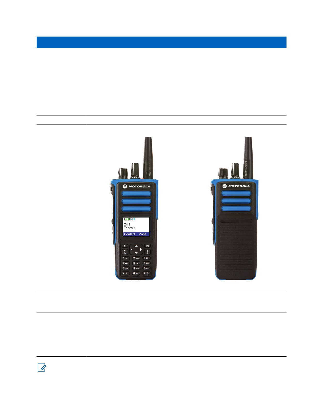
This user guide is written as per the highest tier model offered to the region.
The following table describes ways to access features for different radio models. You receive different
indications depending on the radio model.
Table 2: The Feature Access and Indications of Different Radio Model
Full Keypad Non-Keypad
Radio Model
Figure 1: DP4801 Ex Figure 2: DP4401 Ex
Feature Access
Feature Indication
NOTE: To understand which feature is available with the Programmable Button, you can refer to the
Programmable Buttons on page 24 topic.
● Menu
● Programmable Button
● Tone
● LED indicator
● Display
● Voice Announcement or Text-toSpeech
Programmable Button
● Tone
● LED indicator
● Voice Announcement or Text-toSpeech
15
Page 16
MN008329A01-AC
Chapter 3: Radio Care
Chapter 3
Radio Care
This section describes the basic handling precaution of the radio.
Table 3: IP Specification
IP Specification Description
IP67 Allows your radio to withstand adverse field condi-
tions such as being submersed in water between
15 cm and 1 m for 30 minutes or dust tight for 2–8
hours.
CAUTION: Do not disassemble your radio. This could damage radio seals and result in leak paths into
the radio. Radio maintenance should only be done in service depot that is equipped to test and replace
the seal on the radio.
● If your radio has been submersed in water, shake your radio well to remove any water that may be
trapped inside the speaker grille and microphone port. Trapped water could cause decreased audio
performance.
● If your radio's battery contact area has been exposed to water, clean and dry battery contacts on both
your radio and the battery before attaching the battery to radio. The residual water could short-circuit the
radio.
● If your radio has been submersed in a corrosive substance (for example, saltwater), rinse radio and
battery in fresh water then dry radio and battery.
● To clean the exterior surfaces of your radio, use a diluted solution of mild dishwashing detergent and
fresh water (for example, one teaspoon of detergent to one gallon of water).
● Never poke the vent (hole) located on the radio chassis below the battery contact. This vent allows
for pressure equalization in the radio. Doing so may create a leak path into radio and your radio's
submersibility may be lost.
● Never obstruct or cover the vent, even with a label.
● Ensure that no oily substances come in contact with the vent.
● Your radio with antenna attached properly is designed to be submersible to a maximum depth of 1 m
(3.28 ft) and a maximum submersion time of 30 minutes. Exceeding either maximum limit or use without
antenna may result in damage to your radio.
● When cleaning your radio, do not use a high pressure jet spray on radio as this will exceed the 1 m depth
pressure and may cause water to leak into your radio.
16
Page 17

MN008329A01-AC
Chapter 4: Getting Started
Chapter 4
Getting Started
This chapter provides instructions on how to prepare your radio for use.
4.1
Charging the Battery
For best performance, your radio is powered by a Motorola Solutions-approved Lithium-Ion (Li-lon) battery.
Prerequisites: Turn off your radio when charging.
Procedure:
● To avoid damage and comply with warranty terms, charge the battery using a Motorola Solutios
charger exactly as described in the charger user guide.
● Charge your battery only in non-hazardous areas. After battery is charged, allow your radio to rest for
at least 3 minutes.
● If battery is attached to your radio, ensure that your radio remains powered off while charging.
● Charge a new battery 14 to 16 hours before initial use for best performance.
● Always charge your IMPRES battery with an IMPRES charger for optimized battery life and valuable
battery data.
IMPRES batteries charged exclusively with IMPRES chargers receive a 6-month capacity warranty
extension over the standard Motorola Solutions Premium battery warranty duration.
4.2
Attaching the Battery
Procedure:
1. Align the battery with the rails on the back of the radio.
2. Press the battery firmly, and slide upwards until the latch snaps into place.
3. Slide battery latch into lock position.
17
Page 18

MN008329A01-AC
Chapter 4: Getting Started
Postrequisites:
NOTE:
If the radio is attached with the wrong battery, your radio shows the following indications:
● A low pitched warning tone sounds.
● The red LED blinks.
● The display shows Wrong Battery
● The Voice Announcement or Text‑to‑Speech sounds if loaded using CPS.
If the radio is attached with an unsupported battery, your radio shows the following indications:
● An alert tone sounds.
● The display shows Unknown Battery.
● Battery icon is disabled.
The certification of the radio is voided if you attach a UL battery to an FM approved radio or vice versa.
If your radio is attached with an unsupported, wrong, or unrecognized battery, immediately swap with
the correct battery.
4.3
Removing the Battery
Prerequisites: Ensure that your radio is turned off.
Procedure:
Move the battery latch into unlock position and hold, and slide the battery down and off the rails.
4.4
Attaching the Antenna
Procedure:
1. Set the antenna in the receptacle.
2. Turn the antenna clockwise.
NOTE: Fastening the antenna blocks water and dust from entering the radio.
CAUTION: To prevent damages, replace the faulty antenna with only MOTOTRBO antennas.
4.5
Removing the Antenna
Procedure:
1. Turn the antenna counterclockwise.
2. Remove the antenna from the receptacle.
18
Page 19

Chapter 4: Getting Started
4.6
Attaching the Belt Clip
Procedure:
1. Align the grooves on the clip with the grooves on the battery.
2. Press the belt clip downward until you hear a click sound.
4.7
Removing the Belt Clip
Procedure:
1. Press the belt clip tab away from the battery using a key.
2. Slide the clip upward and away from the radio.
4.8
Attaching the Universal Connector Cover
MN008329A01-AC
Procedure:
1. Insert the slanted end of the cover into the slots above the universal connector.
2. Press downwards on the cover to seat the cover properly on the universal connector.
3. Secure the connector cover to the radio by turning the thumbscrew clockwise.
4.9
Removing the Universal Connector Cover
Procedure:
1. Turn the thumbscrew counterclockwise.
2. Slide the connector cover up and out of the slanted end of the universal connector.
Postrequisites: Replace the dust cover when the universal connector is not in use.
4.10
Turning the Radio On
Procedure:
Turn the On/Off/Volume knob clockwise until a click sounds.
Result:
If your radio is turned on, your radio shows the following indications:
● A tone sounds.
NOTE: If the Tones/Alerts function is disabled, no tone sounds.
● The green LED illuminates.
● The Home screen lights up.
19
Page 20

MN008329A01-AC
Chapter 4: Getting Started
● If voice announcement type is set to Voice Announcement (VA), the Power Up Status Announcement
is enabled and Voice Announcement File is attached, the voice announcement sounds the battery level,
and other service announcements.
● If voice announcement type is set to Text-to-Speech (TTS), and the Power Up Status Announcement
is enabled, the voice announcement sounds the battery level, radio alias, and other service
announcements.
NOTE:
If your radio fails to turn on although your battery is charged and properly attached, contact your dealer
for assistance.
4.11
Turning the Radio Off
Procedure:
Turn the On/Off/Volume knob counterclockwise until a click sounds.
Result: The display shows Powering Down.
4.12
Adjusting the Volume
Procedure:
Perform one of the following actions:
● To increase the volume, turn the On/Off/Volume knob clockwise.
● To decrease the volume, turn the On/Off/Volume knob counterclockwise.
NOTE:
Your radio can be programmed to have a minimum volume offset where the volume level cannot
be lowered past the programmed minimum volume.
20
Page 21
Chapter 5
1
2
3
4
5
6
7
9
8
10
11
12
13
14
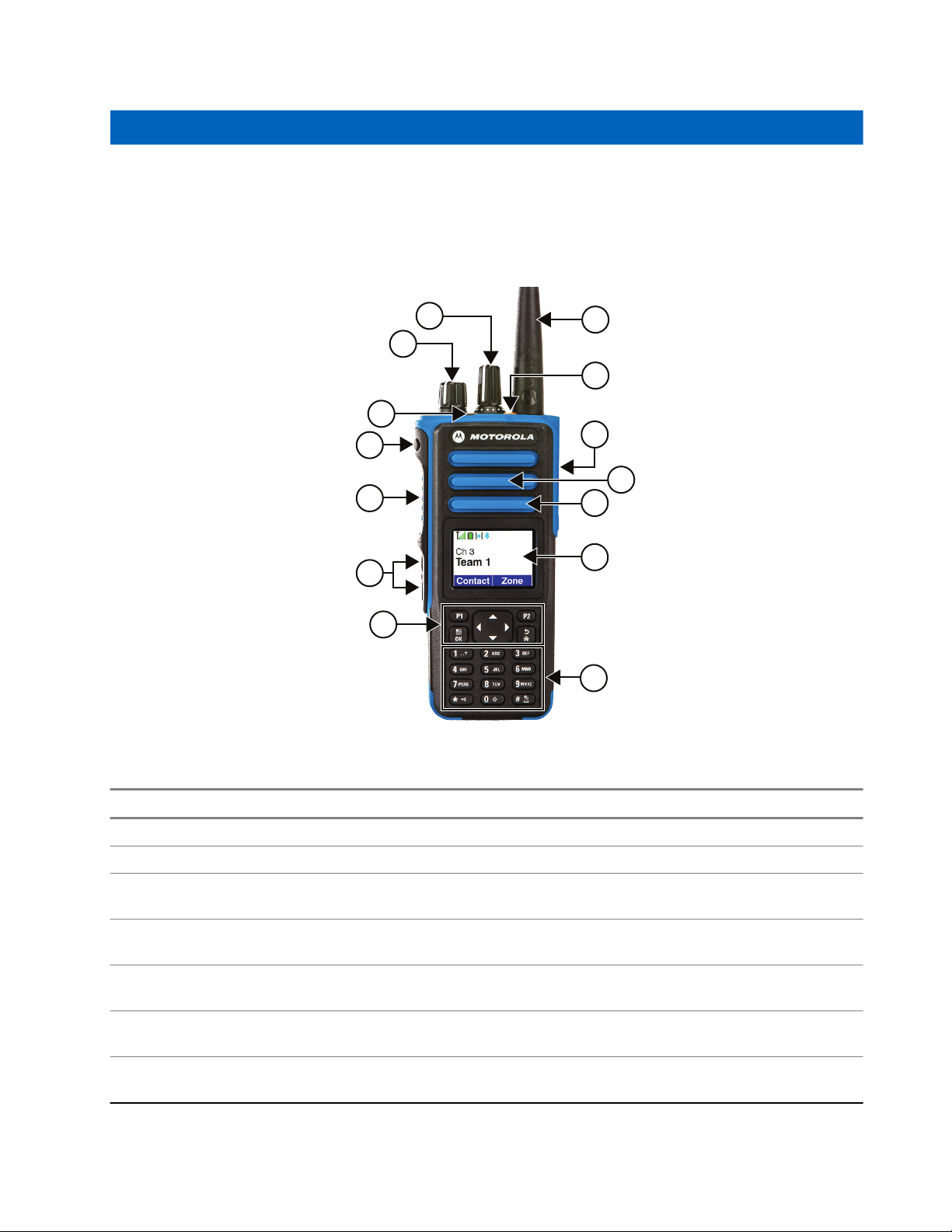
Radio Overview
Radio overview explains the buttons, icons, and LED indications of your radio.
Figure 3: Full Keypad Model
MN008329A01-AC
Chapter 5: Radio Overview
Table 4: Callout Legend
Label Button Name Description
1 Channel Selector knob To select channel.
2 On/Off/Volume knob To turn your radio on or off and adjust volume.
3 LED Indicator The red, green, and orange light-emitting diodes in-
4, 6 Side buttons These buttons are field programmable using the
5 Push-To-Talk (PTT) button To execute voice operations (for example, Group
7 Menu Navigation buttons Five buttons to provide menu navigation and selec-
8 Keypad Twelve keys that allow the user to input characters
dicate operating status.
Customer Programming Software (CPS).
Call and Private Call).
tion interface.
for various text-based operations.
21
Page 22
4
5
6
2
1
11
10
9
7
3
8
MN008329A01-AC
Chapter 5: Radio Overview
Label Button Name Description
9 Liquid Crystal Display (LCD) 132 x 90 highly transflective color display provides
visual information about many radio features.
10 Microphone Allows the voice to be sent when PTT or voice oper-
ations are activated.
11 Speaker Outputs all tones and audio that are generated by
the radio (for example, features like keypad tones
and voice audio).
12 Universal Connector Interface point for all accessories to be used with the
radio. It has 12 points to which specific accessories
will connect and be activated.
13 Emergency button To turn on and off the Emergency Operations.
14 Antenna Provides the needed RF amplification when trans-
mitting or receiving.
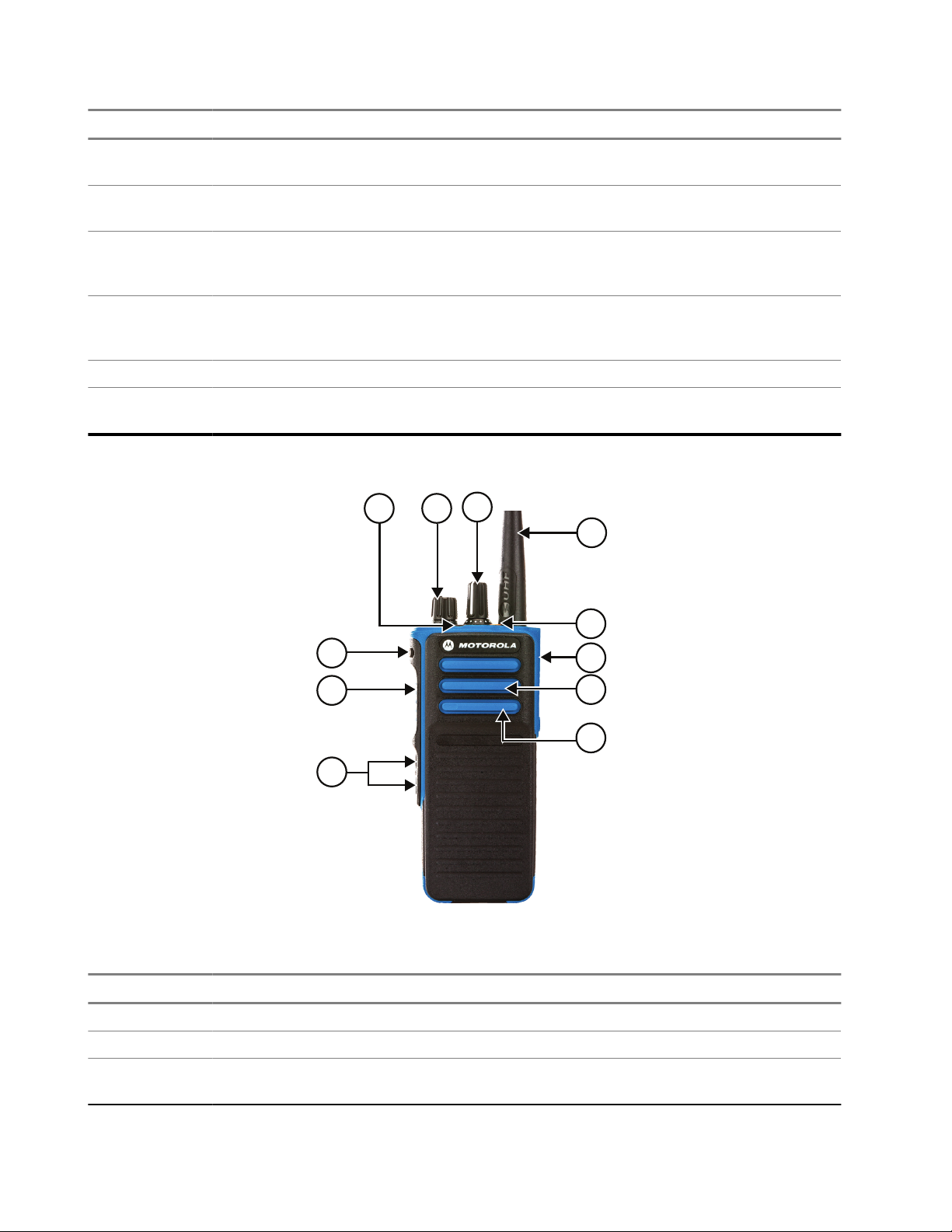
Figure 4: Non-Keypad Model
Table 5: Callout Legend
Label Button Name Description
1 Channel Selector knob To select channel.
2 On/Off/Volume knob To turn your radio on or off and adjust volume.
3 LED Indicator The red, green, and orange light-emitting diodes in-
22
dicate operating status.
Page 23
MN008329A01-AC
Chapter 5: Radio Overview
Label Button Name Description
4, 6 Side buttons These buttons are field programmable using the
Customer Programming Software (CPS).
5 Push-To-Talk (PTT) button To execute voice operations (for example, Group
Call and Private Call).
7 Microphone Allows the voice to be sent when PTT or voice oper-
ations are activated.
8 Speaker Outputs all tones and audio that are generated by
the radio (for example, features like keypad tones
and voice audio).
9 Universal Connector Interface point for all accessories to be used with the
radio. It has 12 points to which specific accessories
will connect and be activated.
10 Emergency button To turn on and off the Emergency Operations.
11 Antenna Provides the needed RF amplification when trans-
mitting or receiving.
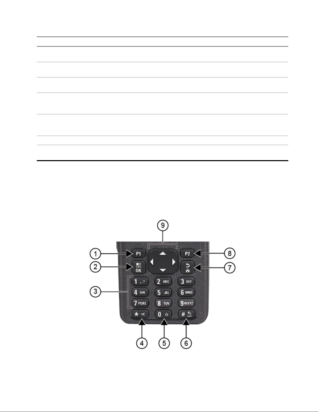
5.1
Keypad Overview
Figure 5: Keypad Overview
23
Page 24

MN008329A01-AC
Chapter 5: Radio Overview
Table 6: Keypad Overview
Label Button Name Description
1 Programmable Button 1
(P1)
2 Menu/OK button Press to access Menu feature.
3 Number keys Press these keys repeatedly until the desired letter, number,
4 * or delete key During numeric entry, press this key to enter *.
5 0 key Press to enter 0.
6 # or space key During numeric entry, press this key to enter #.
7 Back/Home button Press to return to previous screen.
8 Programmable Button 2
(P2)
9 4-Way Navigation but-
tons
This button is field programmable using the Customer Programming Software (CPS).
In the menu, use this key to select.
punctuation, or symbol appears.
During text entry, press this key to delete a character.
Press and hold to enable or disable Caps Lock.
During text entry, press this key to insert a space.
Press and hold this key to change text entry method.
Press and hold to return to home screen.
This button is field programmable using the CPS.
Press up, down, left, and right to navigate through your options.
5.2
Programmable Buttons
You can program the programmable buttons as shortcuts to the following radio functions through Customer
Programming Software (CPS).
NOTE: Contact your dealer for more information.
Table 7: Assignable Radio Functions
Function Description
Acoustic Feedback (AF) Suppressor Allows you to toggle the AF Suppressor feature to
on or off.
All Alert Tones Allows you to toggle all tones and alerts to on or
off.
Audio Profiles Allows you to select the preferred audio profiles.
Audio Routing Allows you to toggle the audio routing between in-
ternal and external speakers.
Backlight Allows you to toggle the display backlight to on or
off.
24
Page 25

MN008329A01-AC
Chapter 5: Radio Overview
Function Description
Backlight Brightness Allows you to adjust brightness level.
Battery Indicator Allows you to check the current status of the bat-
tery level.
Brightness Allows you to adjust the brightness level.
Call Forwarding Allows you to toggle the Call Forwarding to on or
off.
Call Log Allows you to select the call log list.
Cancel Allows the user to cancel an ongoing call, if call
type is Group Call, then only call initiator can use
this button to cancel an ongoing call; if call type is
Private Call, then both the call initiator and receiver
can use this button to cancel an ongoing call.(applicable to Display model only).
Channel Announcement Allows you to play zone and channel announce-
ment voice messages in the current channel.
Contacts Provides direct access to the contacts list.
Display Mode Allows you to toggle to day or night mode
Emergency Off Allows you to terminate an outgoing emergency
call.
Emergency On Allows you to set up an emergency call.
GNSS (Global Navigation Satellite System (GNSS)
On or Off
Allows you to toggle the satellite navigation system
on or off.
Intelligent Audio Allows you to toggle intelligent audio to on or off.
Job Ticket Allows you to access the Job Tickets folder.
Keypad Lock Allows you to toggle the keypad to lock or unlock.
Manual Dial Allows you to initiate Private Call by entering the
subscriber ID.
Manual Site Roam Allows you to start the manual site search.
Mic AGC Allows you to toggle the internal microphone auto-
matic gain control (AGC) to on or off.
Monitor Allows you to monitor a channel.
Mute Mode Allows you to turn Mute Mode on or off.
Notifications Allows you to direct access to the notification list.
Nuisance Delete Allows you to temporarily remove an unwanted
channel from the scan list, except the Selected
Channel. The nuisance deleted channel will be restored into the scan list, for instance, when radio is
powered off and back on again.
One Touch Access Allows you to direct access to the predefined call
features.
25
Page 26

MN008329A01-AC
Chapter 5: Radio Overview
Function Description
Option Board Feature Allows you to toggle the option board feature(s) to
enable or disable the option board-enabled channels.
Permanent Monitor Allows you to monitor a selected channel for all
radio traffic until function is disabled.
Phone Allows you to direct access to the phone contact
list.
Phone Exit Allows the user to terminate a phone call (applica-
ble to Non-Display or Numeric Display model, Digital mode only).
Power Level Allows you to toggle the transmit power to high or
low.
Privacy Allows you to toggle the privacy to on or off.
Radio Check Allows you to check if the radio is active in the
system.
Radio Enable or Disable Allows a target radio to be remotely enabled or
disabled.
Radio Name Displays the radio alias on the radio display.
Remote Monitor Allows you to turn on the microphone of a target
radio without giving any indications.
Repeater or Talkaround Allows you to toggle between using a repeater and
directly communicating with another radio.
Reset Home Channel Allows you to select a new home channel.
Scan Allows you to toggle the scan to on or off.
Silence Home Channel Reminder Allows you to mute the Home Channel Reminder.
Site Info Allows you to view the current Capacity Max or
Other Systems site name and ID.
Site Lock Allows you to enable the site lock to search only
in current site or disable the site lock to search in
other sites as well.
Status Allows you to select the status list menu.
Telemetry Control Allows you to control the output pin on a local or
remote radio.
Text Message Allows you to select the text message menu.
Toggle Call Priority Level Allows you to enable your radio to enter Call Priori-
ty Level High or Normal.
Transmit Interrupt Allows you to stop an on-going voice call by dekey-
ing the transmitting radio or terminate the repeater
call hang time in order to free up the channel. This
button can also be used to end a Remote Monitor
session.
Trill Enhancement Allows you to toggle the trill enhancement to on or
off.
26
Page 27
MN008329A01-AC
Chapter 5: Radio Overview
Function Description
Unassigned Indicates that the button function has not yet as-
signed.
Voice Announcement Allows you to toggle the voice announcement to on
or off.
Voice Operating Transmission (VOX) Allows you to toggle the VOX to on or off.
Zone Selection Allows you to select from a list of zones.
Zone Toggle Allows you to switch between 2 zones.
5.3
Icons
Icons are only available for radio with display.
Your radio display shows the radio status, text entries, and menu entries.
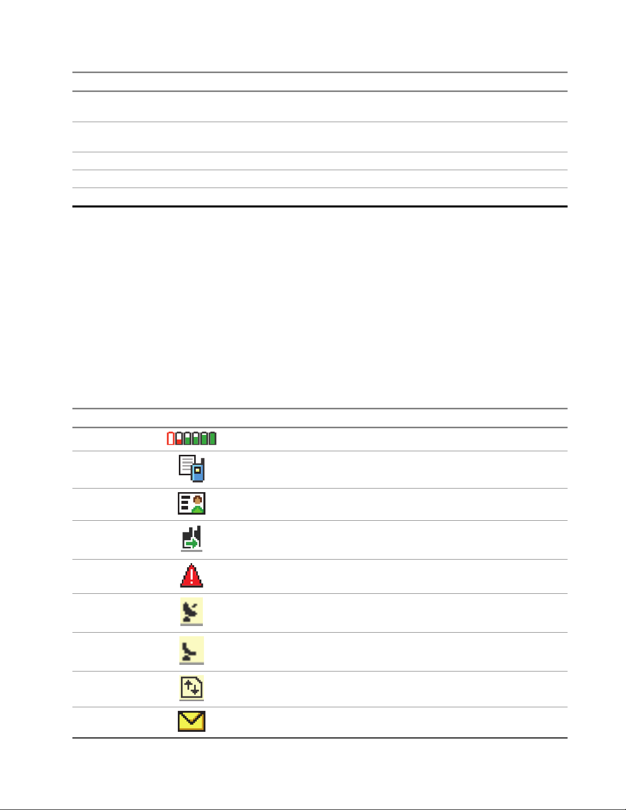
5.3.1
Display Icons
The following icons appear on the status bar at the top of the radio display. The icons are arranged left most
in order of appearance or usage, and are channel-specific.
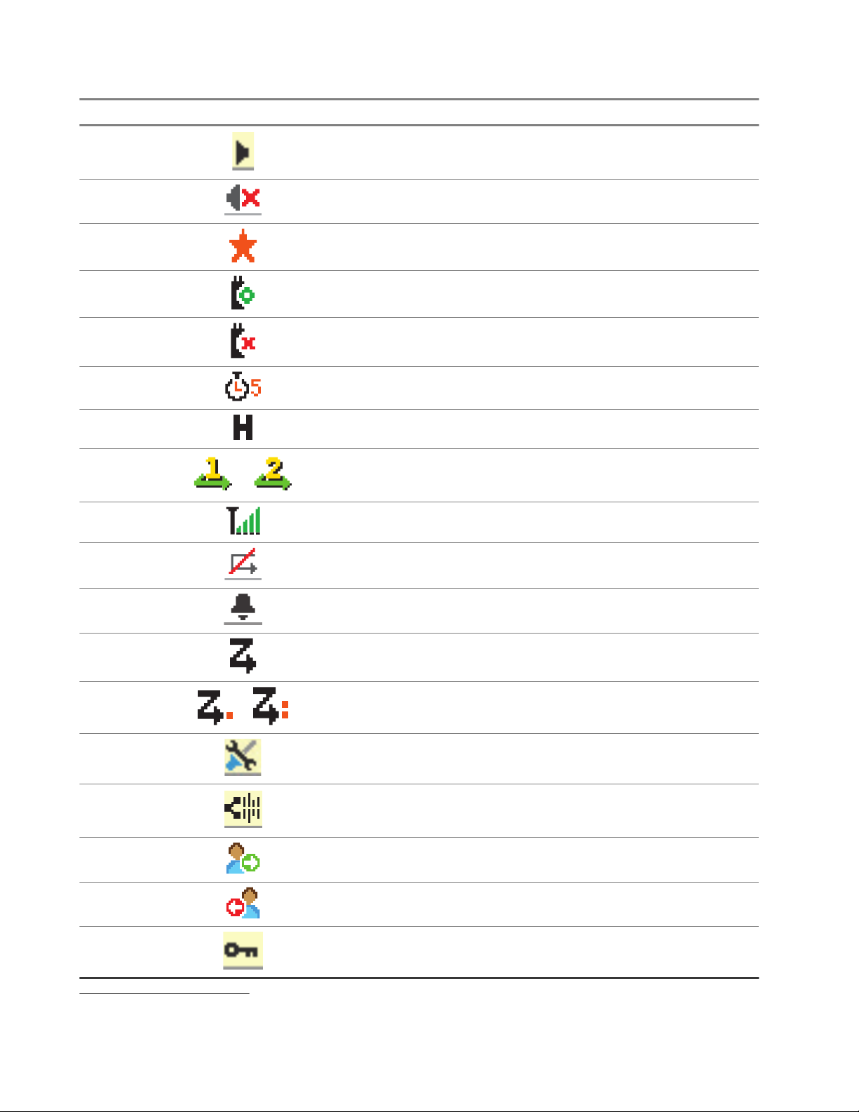
Table 8: Display Icons
Icon Description
Battery
Call Log
Contact
DGNA
Emergency
GNSS Available
GNSS Not Available
High Volume Data
Message
27
Page 28
MN008329A01-AC
Chapter 5: Radio Overview
Icon Description
Monitor
Mute Mode
Notification
Option Board
Option Board Non-Function
Over-the-Air Programming Delay Timer
Power Level
or
or
Priority Talkgroup 1 or 2
Received Signal Strength Indicator (RSSI)
Response Inhibit
Ring Only
1
Scan
Scan Priority 1 or 2
1
Service & Support
Shared Frequency
Sign In to Remote Server
2
1
Not Applicable in Capacity Plus.
2
Only available for Full Keypad.
28
Sign Out from Remote Server
Secure
2
Page 29
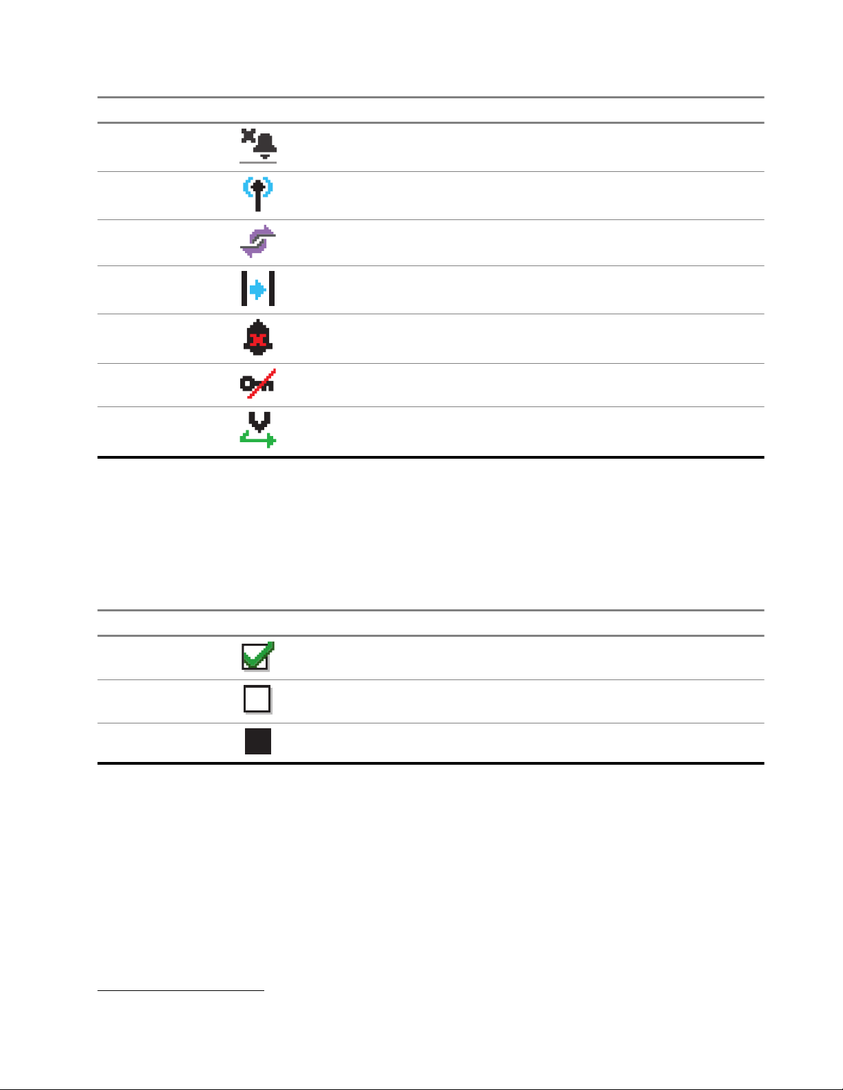
Icon Description
Silent Ring
MN008329A01-AC
Chapter 5: Radio Overview
Site Roaming
Status
Talkaround
Tones Disable
Unsecure
Vote Scan
3
1
5.3.2
Advanced Menu Icons
The following icons appear beside menu items that offer a choice between two options or as an indication
that there is a sub-menu offering two options.
Table 9: Advanced Menu Icons
Icon Description
Checkbox (Checked)
Checkbox (Empty)
Solid Black Box
5.3.3
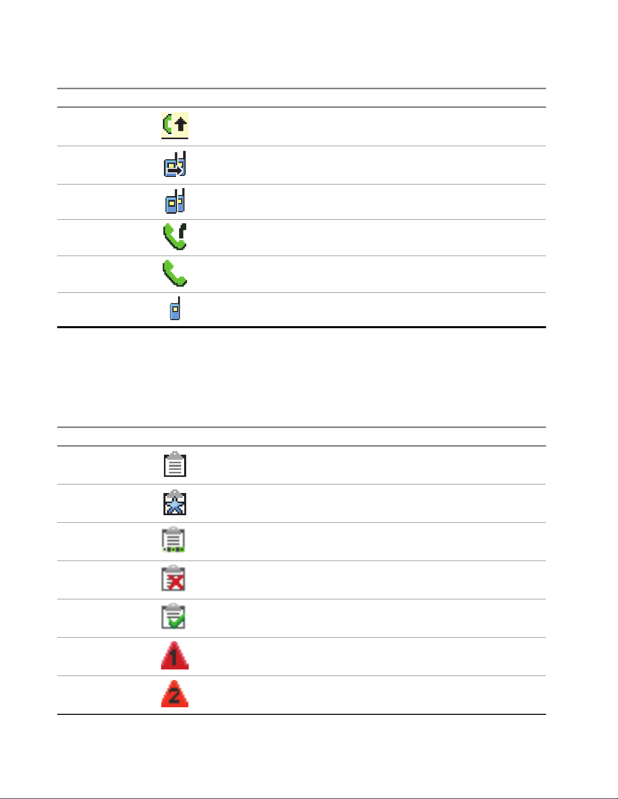
Call Icons
The following icons appear on the display during a call. These icons also appear in the Contacts list to
indicate alias or ID type.
3
Not applicable in Capacity Plus-Single-Site.
29
Page 30
MN008329A01-AC
Chapter 5: Radio Overview
Table 10: Call Icons
Icon Description
Call Priority High
DGNA Call
Group Call/All Call
Phone Call as Group or All Call
Phone Call as Private Call
Private Call
5.3.4
Job Tickets Icons
The following icons appear momentarily on the display in the Job Ticket folder.
Table 11: Job Ticket Icons
Icon Description
All Jobs
New Jobs
In Progress
Send Failed
Sent Successfully
30
Priority 1
Priority 2
Page 31

MN008329A01-AC
Chapter 5: Radio Overview
Icon Description
Priority 3
5.3.5
Mini Notice Icons
The following icons appear momentarily on the display after an action to perform a task is taken.
Table 12: Mini Notice Icons
Icon Description
Failed Transmission (Negative)
Successful Transmission (Positive)
Transmission in Progress (Transitional)
5.3.6
Sent Items Icons
The following icons appear at the top right corner of the display in the Sent Items folder.
Table 13: Sent Item Icons
Icon Description
In Progress
or
Individual or Group Message Read
or
Individual or Group Message Unread
or
Send Failed
or
Sent Successfully
or
5.4
LED Indications
The LED Indicator shows the operational status of your radio.
A qualified technician can permanently disable the LED indication by preprogramming it.
31
Page 32

MN008329A01-AC
Chapter 5: Radio Overview
Table 14: LED Indications
Indication Status
Blinking Red
Solid Yellow
Blinking Yellow
Double Blinking Yellow
● The radio is indicating a battery mismatch.
● The radio has failed the self-test upon powering up.
● The radio is receiving an emergency transmission.
● The radio is transmitting in low battery state.
● The radio has moved out of range if Auto-Range Transponder
System is configured.
● Mute Mode is enabled.
● The radio is in Bluetooth Discoverable Mode.
● The radio is monitoring a conventional channel.
● Indicates fair battery capacity when the programmed Battery In-
dicator button is pressed.
● The radio has yet to respond to a Call Alert.
● The radio is scanning for activity.
● All Capacity-Plus–Multi-Site channels are busy.
● The radio has Auto Roaming enabled.
● The radio is actively searching for a new site.
● The radio has yet to respond to a Group Call Alert.
● The radio is locked.
● The radio is not connected to the repeater while in Capacity Plus.
● All Capacity-Plus channels are busy.
Solid Green
● The radio is powering up.
● The radio is transmitting.
● The radio is sending a Call Alert or an emergency transmission.
● Indicates full battery capacity when the programmed Battery In-
dicator button is pressed.
Blinking Green
● The radio is receiving a call or data.
● The radio is retrieving the Over-the-Air Programming transmissions.
● The radio is detecting activity over the air.
NOTE: The activity may or may not affect the programmed
channel of the radio due to the nature of the digital protocol.
Double Blinking Green The radio is receiving a privacy-enabled call or data.
32
Page 33

MN008329A01-AC
Chapter 6: System Overview
Chapter 6
System Overview
System overview explains what type of systems and modes available in the radio.
6.1
Capacity Max
Capacity Max is MOTOTRBO control channel based trunked radio system.
MOTOTRBO digital radio products are marketed by Motorola Solutions primarily to business and industrial
users. MOTOTRBO uses the European Telecommunications Standards Institute (ETSI) Digital Mobile Radio
(DMR) standard, that is, two-slot Time Division Multiple Access (TDMA), to pack simultaneous voice or data
in a 12.5 kHz channel (6.25 kHz equivalent).
6.2
Other Systems
Other Systems include Conventional Analog and Digital modes, IP site connect, and Capacity Plus.
6.2.1
Conventional Analog and Digital Modes
Each channel in your radio can be configured as a conventional analog or conventional digital channel.
Certain features are unavailable when switching from digital to analog mode and analog to digital mode,
whereas some are available in both.
There are minor differences on how each feature works but they do not affect the performance of your radio.
6.2.2
IP Site Connect
This feature allows your radio to extend conventional communication beyond the reach of a single site by
connecting to different available sites by using an Internet Protocol (IP) network. This is a conventional
multi-site mode.
When the radio moves out of range from one site and into the range of another, the radio connects to the
repeater of the new site to send or receive calls or data transmissions. This is done either automatically or
manually depending on your settings.
In an automatic site search, the radio scans through all available sites when the signal from the current site
is weak or when the radio is unable to detect any signal from the current site. The radio then locks on to the
repeater with the strongest Received Signal Strength Indicator (RSSI) value.
In a manual site search, the radio searches for the next site in the roam list that is currently in range but
which may not have the strongest signal and locks on to the repeater.
NOTE: Each channel can only have either Scan or Roam enabled, not both at the same time.
33
Page 34

MN008329A01-AC
Chapter 6: System Overview
Channels with this feature enabled can be added to a particular roam list. The radio searches the channels in
the roam list during the automatic roam operation to locate the best site. A roam list supports a maximum of
16 channels, including the selected channel.
NOTE: You cannot manually add or delete an entry in the roam list. Contact your dealer for more
information.
6.2.3
Capacity Plus
Capacity Plus is a cost effective and entry-level digital trunked system. It expands the capacity and extends
the coverage for single and multi-sites. The single and multi-sites dynamic trunking offers better capacity and
coverage.
NOTE: If you try to access a feature not applicable to Capacity Plus–Single-Site or Capacity Plus–MultiSite by using a programmable button, you hear a negative indicator tone.
Capacity Plus–Single-Site
Capacity Plus–Single-Site is a single-site trunking configuration of the MOTOTRBO radio system, which uses
a pool of channels to support hundreds of users and up to 254 groups.
This configuration allows your radio to efficiently utilize the number of available programmed channels while
in Repeater Mode.
Your radio also has features that are available in conventional digital mode, IP Site Connect, and Capacity
Plus.
Capacity Plus–Multi-Site
Capacity Plus–Multi-Site is a multi-channel trunking configuration of the MOTOTRBO radio system,
combining the best of both Capacity Plus and IP Site Connect configurations. It is also known as Linked
Capacity Plus.
It allows your radio to extend trunking communication beyond the reach of a single site, by connecting to
different available sites which are connected with an IP network. It also provides an increase in capacity
by efficiently utilizing the combined number of available programmed channels supported by each of the
available sites.
When your radio moves out of range of one site and into the range of another, it connects to the repeater
of the new site to send or receive calls or data transmissions. Depending on your settings, this is done
automatically or manually.
Automatically
Your radio scans through all available sites when the signal from the current site is weak or unable to
detect any signal and locks on to the repeater with the strongest RSSI value.
Manually
Your radio searches for the next site in the roam list that is currently in range which may not have the
strongest signal, and locks on to it.
Any channel with Capacity Plus Multi-Site enabled can be added to a roam list. Your radio searches these
channels during the automatic roam operation to locate the best site.
NOTE: You cannot manually add or delete an entry in the roam list.
34
Page 35

Capacity Max
Other Systems
MN008329A01-AC
Chapter 7: Registration
Chapter 7
Registration
Supported systems:
Your radio may receive registration-related messages from your Capacity Max system.
Registration
Your radio sends registration message to a system when you turn on your radio, change talkgroup, or site
roam. If your radio fails to register on site, your radio automatically attempts to roam to another site, and
temporarily removes the registration site attempted from the roaming list.
When site searches successfully, your radio shows the following indications:
● A tone sounds.
● The yellow LED double blinks.
● The display shows Registering.
When site registered successfully, your radio shows Site <Number>.
Out of Range
When your radio unable to detect a signal from the system or from the current site, your radio shows the
following indications:
● A repetitive tone sounds.
● The RED blinks.
● The display shows Out of range.
Talkgroup Affiliation Failed
When your radio fails to attempt affiliation to the talkgroup specified in the channels or Unified Knob Position
(UKP) during registration, your radio shows UKP Alias.
Registration Denied
When registration with the system is not accepted, your radio shows the following indications:
● The yellow LED double blinks.
● The display shows Registration Denied.
35
Page 36

Capacity Max
Other Systems
MN008329A01-AC
Chapter 8: Zone and Channel Selections
Chapter 8
Zone and Channel Selections
Supported systems:
A zone is a group of channels. You can program each channel with different features that support different
groups of users.
Table 15: Number of Supported Zones and Channels
Model Zones Channels Channels per Zone
Full Keypad and Limi-
ted Keypad
Non-Keypad 4 64 16
8.1
250 1000 160
Selecting Zones
Procedure:
From the menu, select Zone → <required Zone>.
Result: The display shows <Zone> Selected.
8.2
Selecting Zones Using Alias Search
Procedure:
1. From the menu, select Zone.
2. Enter the required characters for the alias.
Result:
The display shows <Zone> Selected.
.
36
NOTE: The alias search is case-insensitive. If there are two or more entries with the same name, the
display shows the entry listed first in the list.
Page 37

MN008329A01-AC
Chapter 8: Zone and Channel Selections
8.3
Selecting Channels
Procedure:
Turn the Channel Selector knob.
NOTE: If Virtual Channel Stop is enabled, your radio stops proceeding beyond the first or the last
channel, and a tone is heard.
Result: Your radio switches to your preferred channel.
8.4
Selecting Channels Using Direct Channel Dial
Procedure:
At the home screen, enter the <required channel number> → Menu/OK.
37
Page 38

Capacity Max
Other Systems
Capacity Max
Other Systems
MN008329A01-AC
Chapter 9: Site Overview
Chapter 9
Site Overview
A site provides coverage for a specific area.
In a multi-site network, the system will automatically search for a new site when the signal level from the
current site drops to an unacceptable level.
9.1
Site Restriction
Supported systems:
For site restriction, your radio dealer has the ability to decide which network sites to be used by your radio.
Your radio does not need to be reprogrammed to change the list of allowed and disallowed sites.
If your radio attempts to register at a disallowed site, your radio receives indication that the site is denied and
then searches for a different network site.
When experiencing site restrictions, your radio shows the following indications:
● The yellow LED blinks double indicating site search.
● The display shows Register Denied or Site <Number> Not Allowed.
9.2
Site Trunking
Supported systems:
Site Trunking is only available with Capacity Max system. A site must be able to communicate with the Trunk
Controller to be considered as System Trunking.
If the site cannot communicate with the Trunk Controller in the system, a radio enters Site Trunking mode.
While in Site Trunking, the radio provides a periodic audible and visual indication to the user to inform the
user of their limited functionality.
When a radio is in Site Trunking, the radio displays Site Trunking and a repetitive tone sounds.
When a radio is in Site Trunking, a repetitive tone sounds.
The radios in Site Trunking are still able to make group and individual voice calls as well as send text
messages to other radios within the same site. Voice consoles, logging recorders, phone gateways, and data
applications cannot communicate to the radios at the site.
Once in Site Trunking, a radio that is involved in calls across multiple sites will only be able to communicate
with other radios within the same site. Communication to and from other sites would be lost.
NOTE: If there are multiple sites that cover the current location of the radio and one of the sites enters
Site Trunking, the radio roams to another site if within coverage.
38
Page 39

9.3
Capacity Max
Other Systems
Capacity Max
Other Systems
Capacity Max
Other Systems
Turning the Site Lock On
Supported systems:
Procedure:
From the menu, select Utilities → Radio Settings → Site Roaming → Site Lock → On.
9.4
Turning the Site Lock Off
Supported systems:
Procedure:
MN008329A01-AC
Chapter 9: Site Overview
From the menu, select Utilities → Radio Settings → Site Roaming → Site Lock → Off.
9.5
Enabling the Manual Site Search
Supported systems:
Procedure:
From the menu, select Utilities → Radio Settings → Site Roaming → Active Search.
Result: Your radio shows the following indications:
● A tone sounds.
● The green LED blinks.
● The display shows Finding Site.
If your radio finds a new site, your radio shows the following indications:
● A positive tone sounds.
● The LED extinguishes.
● The display shows Site <Number> Found.
If your radio fails to find a new site, your radio shows the following indications:
● A negative tone sounds.
● The LED extinguishes.
● The display shows Out of Range.
If a new site is within the range, but your radio is unable to connect to it, your radio shows the following
indications:
● A negative tone sounds.
39
Page 40

Capacity Max
Other Systems
MN008329A01-AC
Chapter 9: Site Overview
● The LED extinguishes.
● The display shows Channel Busy.
9.6
Accessing Neighbor Sites List
Supported systems:
Procedure:
From the menu, select Utilities → Radio Info → Neighbor Sites.
40
Page 41

Capacity Max
Other Systems
MN008329A01-AC
Chapter 10: Types of Radio Calls
Chapter 10
Types of Radio Calls
Supported systems:
There are several ways that you can make a call with your radio depending on the types of calls and system
available on your radio.
Table 16: Types of Radio Calls
Call Type Capacity Max Other System
Group Call
A Group Call is a point-to-multipoint call operation. Your radio must be configured as a member of the group for you to communicate with
each other.
Broadcast Call
A Broadcast Call is a one-way voice call from
any user to an entire talkgroup.
The Broadcast Call feature allows only the call
initiating user to transmit to the talkgroup, while
the recipients of the call cannot respond.
Private Call
A Private Call is a call from an individual radio to
another individual radio.
There are two types of Private call which are:
● Off Air Call Set-Up (OACSU)
● Full Off Air Call Set-Up (FOACSU)
All Call
An All Call is a call from an individual radio to
every radio on the site or every radio at a group
of sites. It is used to make important announcement.
Selective Call
A Selective Call is a call from an individual radio
to another individual radio. It is a Private Call on
an analog system.
4
5
4
OACSU sets up the call after performing a radio presence check and completes the call automatically.
5
FOACSU sets up the call after performing a radio presence check. FOACSU calls require user
acknowledgment to complete the call and allows the user to either Accept or Decline the call.
41
Page 42

MN008329A01-AC
Chapter 10: Types of Radio Calls
Call Type Capacity Max Other System
Unaddressed Call
An Unaddressed Call is a group call to one of
the 16 predefined group IDs.
Open Voice Chanel Mode (OVCM)
An OVCM is a call from a radio that is not preconfigured to work in a particular system during
a group or individual call. The OVCM group call
supports broadcast calls.
When a call is interrupted, you hear a continuous Talk Prohibit Tone. Releasing the PTT button allows you to
receive the call.
Channel Free Indication feature can be programmed on your radio by your dealer. If the Channel Free
Indication feature is enabled, you hear a short alert tone when the recipient releases the PTT button,
indicating the channel is free for you to respond.
10.1
Making Calls on the Radio
Procedure:
Perform one of the following actions based on the type of calls:
Option Actions
Making group calls, private calls, unaddressed
calls, or selective calls
Making broadcast calls, all calls, or OVCM calls
If your radio does not detect voice activity for a predetermined period, the call ends.
a. Select a channel with an active ID or alias.
b. To call, press and hold the PTT button.
c. Wait for the Talk Permit Tone to end, and
speak into the microphone.
d. To listen, release the PTT button.
a. Select a channel with an active group ID or
alias.
b. To call, press and hold the PTT button.
c. Wait for the Talk Permit Tone or PTT Side-
tone to end, and speak into the microphone.
42
Page 43

10.2
Making Calls with Contact List
Procedure:
Perform one of the following actions based on the type of calls:
Option Actions
MN008329A01-AC
Chapter 10: Types of Radio Calls
Making group calls or private calls with Contact
List
Making broadcast calls or all calls with Contact
List
a. From the menu, select Contacts.
b. Perform one of the following actions:
● To do alias search, enter the required
characters for the alias.
● To search for the alias manually, scroll
down the contact list with the 4-Way Nav-
igation button.
c. To call, press and hold the PTT button.
d. Wait for the Talk Permit Tone to end, and
speak into the microphone.
e. To listen, release the PTT button.
a. From the menu, select Contacts.
b. Perform one of the following actions:
● To do alias search, enter the required
characters for the alias.
● To search for the alias manually, scroll
down the contact list with the 4-Way Nav-
igation button.
c. To call, press and hold the PTT button.
d. Wait for the Talk Permit Tone to end, and
speak into the microphone.
10.3
Making Calls with Manual Dial
The following steps are applicable to Private Call only.
Procedure:
1. From the menu, select Contacts → Manual Dial → Radio Number.
2. To enter or edit the ID, enter the required numbers.
3. To call, press and hold the PTT button.
4. Wait for the Talk Permit Tone to end, and speak into the microphone.
5. To listen, release the PTT button.
43
Page 44

MN008329A01-AC
Chapter 10: Types of Radio Calls
10.4
Making Calls with Programmable Number Keys
Procedure:
Perform one of the following actions based on the type of calls:
Option Actions
Making group calls or private calls with Programmable Number Keys
Making broadcast calls or all calls with Programmable Number Keys
a. From the home screen, to make a call to
the predefined alias, press and hold the programmed number key.
b. To call, press and hold the PTT button.
c. Wait for the Talk Permit Tone to end, and
speak into the microphone.
d. To listen, release the PTT button.
a. From the home screen, to make a call to
the predefined alias, press and hold the programmed number key.
b. To call, press and hold the PTT button.
c. Wait for the Talk Permit Tone to end, and
speak into the microphone.
10.5
Receiving and Responding to Calls on the Radio
When you receive calls, your radio shows the following indications:
● The green LED blinks.
● Your radio unmutes and the incoming call sounds through the speaker.
● The display shows the ID and alias and call status.
NOTE: You cannot respond to a Broadcast Call or All Call. For Broadcast Call, the display shows
Talkback Prohibit and the Talkback Prohibit tone sounds when the PTT button is pressed.
Procedure:
1. To respond, press and hold the PTT button.
2. Wait for the Talk Permit Tone to end, and speak into the microphone.
3. To listen, release the PTT button.
10.6
Accepting or Declining Private Calls
When you receive Private Calls configured as Full Off Air Call Set-Up (FOACSU), your radio shows the
following indications:
● The green LED blinks.
44
Page 45

● The display shows the alias and the Private Call icon.
Accepting Private Calls
Procedure:
1. To accept Private Calls, perform one of the following actions:
● Select Accept.
● Press and hold the PTT button.
2. Wait for the Talk Permit Tone to end, and speak into the microphone.
3. To listen, release the PTT button.
Declining Private Calls
Procedure:
To decline Private Calls, perform one of the following actions:
● Select Reject.
● Select the Back/Home button.
● For Non-Keypad radio, press the programmed Cancel button.
MN008329A01-AC
Chapter 10: Types of Radio Calls
45
Page 46

Capacity Max
Other Systems
MN008329A01-AC
Chapter 11: Phone Calls
Chapter 11
Phone Calls
Supported systems:
A Phone Call is a call in between an individual radio or a group of radios and a telephone.
Depending on how the radio is configured, the following features may or may not be made available:
● Access code.
● Dual Tone Multi Frequency (DTMF) tone.
● De-access code.
● Displaying of caller alias or ID on receiving a phone call.
● Ability to reject or accept a phone call.
The Phone Call capability can be enabled by assigning and setting up phone numbers on the system.
Contact your dealer to determine how your radio has been programmed.
11.1
Making Phone Calls
Procedure:
1. From the menu, select Phone → <required ID> → <Access Code>.
2. To call, press and hold the PTT button.
3. To listen, release the PTT button.
4. While you are in the Phone call, you can perform any of the following actions if required:
● Enter extra digits by using the Keypad.
● To end the call, select the Back/Home button.
● To deaccess a code, enter the deaccess code by using the Keypad when the display shows
De-Access Code:.
Result: If the call ends successfully, your radio shows the following indications:
● A tone sounds.
● The display shows Call Ended.
11.2
Making Phone Calls with Contact List
Procedure:
1. From the menu, select Contacts.
2. Perform one of the following actions:
46
● To do alias search, enter the required characters for the alias.
Page 47

● To search for the alias manually, scroll down the contact list with the 4-Way Navigation button.
Capacity Max
Other Systems
3. Select Call Phone → <Access Code>.
4. To call, press and hold the PTT button.
5. To listen, release the PTT button.
6. While you are in the Phone call, perform one of the following actions:
● Enter extra digits by using the Keypad.
● To end the call, select the Back/Home button.
● To deaccess a code, enter the deaccess code when the display shows De-Access Code:.
Result: If the call ends successfully, your radio shows the following indications:
● A tone sounds.
● The display shows Call Ended.
11.3
Making Phone Calls with Manual Dial
MN008329A01-AC
Chapter 11: Phone Calls
Procedure:
1. From the menu, select Contacts → Manual Dial → Phone Number.
2. Enter the phone number and <Access Code>.
3. To call, press and hold the PTT button.
4. To listen, release the PTT button.
5. While you are in the Phone call, perform one of the following actions:
● Enter extra digits by using the Keypad.
● To end the call, select the Back/Home button.
● To deaccess a code, enter the deaccess code when the display shows De-Access Code:.
Result: If the call ends successfully, your radio shows the following indications:
● The display shows Call Ended.
11.4
Dual Tone Multi Frequency
Supported systems:
The Dual Tone Multi Frequency (DTMF) feature allows your radio to operate in a radio system with an
interface to the telephone systems.
11.4.1
Initiating the DTMF Tone
Procedure:
1. Press and hold the PTT button.
47
Page 48

MN008329A01-AC
Chapter 11: Phone Calls
2. To initiate a DTMF tone, perform one of the following actions:
● Enter the <desired number>.
● Press the * or # button.
NOTE: Disabling all radio tones and alert will automatically turn off the DTMF tone.
11.5
Receiving and Responding to Phone Calls
When you receive a phone call, your radio shows the following indications:
● The green LED blinks.
● Your radio unmutes and the incoming call sounds through the speaker.
● The display shows the Phone Call icon and the call status.
Procedure:
1. To respond to the phone call, press and hold the PTT button.
2. Wait for the Talk Permit Tone to end, and speak into the microphone.
3. To listen, release the PTT button.
4. To end the call, select the Back/Home button.
NOTE: Your radio is not able to terminate a phone call as a group call. The telephone user must
end the call. The recipient user is only allowed to talk back during the call.
Result: If the call ends successfully, your radio shows the following indications:
● A tone sounds.
● The display shows Call Ended.
48
Page 49

Capacity Max
Other Systems
MN008329A01-AC
Chapter 12: Call Preemption
Chapter 12
Call Preemption
Supported systems:
Call Preemption allows your radio to interrupt any ongoing calls and initiate a higher priority call.
With the Call Preemption feature, the system interrupts any ongoing calls whereby trunked channels are
unavailable.
Thus your radio initiates a higher priority call such as an emergency call or all call. If no other Radio
Frequency (RF) channels are available, emergency call will interrupt all call as well.
49
Page 50

Capacity Max
Other Systems
MN008329A01-AC
Chapter 13: Voice Interrupt
Chapter 13
Voice Interrupt
Supported systems:
Voice Interrupt allows your radio to end any ongoing calls.
The Voice Interrupt feature uses the reverse channel signaling to interrupt any ongoing calls. You are allowed
to make a voice transmission during the interruption.
The Voice Interrupt feature improves the probability of delivering a new call to the recipients when a call is in
progress.
Voice Interrupt is accessible if this feature has been programmed in your radio. Contact your dealer for more
information.
13.1
Enabling the Voice Interrupt
Procedure:
1. To interrupt the transmission during an on-going call, press and hold the PTT button.
2. Wait for the Talk Permit Tone to end, and speak into the microphone.
50
Page 51

Capacity Max
Other Systems
Chapter 14: Initiating Transmit Interrupt
Chapter 14
Initiating Transmit Interrupt
Supported systems:
Procedure:
To interrupt an ongoing call, perform one of the following actions:
● Press the PTT button.
● Press the Emergency button.
● For Other Systems, perform data transmission.
● For Other Systems, press the programmed TX Interrupt Remote Dekey button.
MN008329A01-AC
51
Page 52

Capacity Max
Other Systems
MN008329A01-AC
Chapter 15: Advanced Features
Chapter 15
Advanced Features
This chapter explains the operations of the features available in your radio.
15.1
Analog Message Encode
Supported systems:
Your radio can send preprogrammed messages from the Message list to a radio alias or the dispatcher.
15.1.1
Sending MDC Encode Messages to Dispatchers
Procedure:
From the menu, select Message → Quick Text → <required message>.
Result:
If the request is successful, your radio shows the following indications:
● A positive indicator tone sounds.
● The display shows a positive mini notice.
If the request is unsuccessful, your radio shows the following indications:
● A negative indicator tone sounds.
● The display shows a negative mini notice.
15.1.2
Sending 5-Tone Encode Messages to Contacts
Procedure:
From the menu, select Message → Quick Text → <required message> → <required contact>.
Result:
If the request is successful, your radio shows the following indications:
● A positive indicator tone sounds.
● The display shows a positive mini notice.
If the request is unsuccessful, your radio shows the following indications:
● A negative indicator tone sounds.
● The display shows a negative mini notice.
52
Page 53

Capacity Max
Other Systems
MN008329A01-AC
Chapter 15: Advanced Features
15.2
Analog Status Update
Supported systems:
Your radio can send preprogrammed messages from the Status List indicating your current activity to a radio
contact (for 5-Tone systems) or the dispatcher (for Motorola Data Communication systems).
For Motorola Data Communication (MDC) systems, the last acknowledged message is kept at the top of the
Status list. The other messages are arranged in alphanumeric order.
15.2.1
Sending Status Updates to Predefined Contacts
Procedure:
Perform one of the following actions:
● For Motorola Data Communication (MDC) systems, from the menu, select Status → <required
status> → Set as Default → Menu/OK.
● For 5-Tone systems, from the menu, select Status → <required status> → Set as Default.
For 5-Tone systems, if you press the PTT button while in the Status List, you radio sends the selected
status update and returns to the home screen to start a voice call.
Result:
For MDC systems, if the request is successful, your radio shows the following indications:
● A positive indicator tone sounds.
● The display shows a positive mini notice.
For MDC systems, if the request is unsuccessful, your radio shows the following indications:
● A negative indicator tone sounds.
● The display shows a negative mini notice.
For 5-Tone systems, if the request is successful, your radio display shows a
status.
For 5-Tone systems, if the request is unsuccessful, your radio display shows a beside the previous status.
beside the acknowledged
15.2.2
Viewing 5-Tone Status Details
Prerequisites: Purchase the Software License Key.
Procedure:
From the menu, select Status → <required status> → View Details.
Result: The display shows details of the selected status.
53
Page 54

Capacity Max
Other Systems
Capacity Max
Other Systems
MN008329A01-AC
Chapter 15: Advanced Features
15.2.3
Editing 5-Tone Status Details
Procedure:
1. From the menu, select Status → <required status> → Edit.
2. To edit the status details, use the following keys:
● To move the cursor to the left or right, select the 4-Way Navigation buttons.
● To delete characters, select the * key.
● To change the text entry method, select and hold the # key.
3. When editing is completed, select the Menu/OK button.
Result: The display shows a positive mini notice.
15.3
Auto-Range Transponder System
Supported systems:
The Auto-Range Transponder System (ARTS) is an analog-only feature designed to inform you when your
radio is out-of-range of other ARTS-equipped radios.
ARTS-equipped radios transmit or receive signals periodically to confirm that they are within range of each
other.
Your radio provides indications as follows:
Table 17: Auto-Range Transponder System Indications
Indication Description
First-Time Alert
ARTS-in-Range Alert
ARTS-Out-of-Range Alert
● A tone sounds.
● The display shows In Range after the channel alias.
● A tone sounds, if programmed.
● The display shows In Range after the channel alias.
● A tone sounds.
● The red LED rapidly blinks.
● The display shows Out of Range alternating with the Home
screen.
15.4
Call Alert Operation
Supported systems:
54
Page 55

Capacity Max
Other Systems
MN008329A01-AC
Chapter 15: Advanced Features
Call Alert paging enables you to alert the recipient to call you back when they can. This feature is applicable
for subscriber aliases or IDs only.
For Capacity Max, the Call Alert feature allows radio users or dispatchers to alert recipients to call back
the caller when available. Voice communication is not involved in this feature. Off Air Call Set-Up (OACSU)
private calls allows you to respond immediately. Full Off Air Call Set-Up (FOACSU) private calls requires you
to acknowledge the call. OACSU type calls are recommended for the Call Alert feature.
15.4.1
Making Call Alerts
Procedure:
Perform one of the following actions:
Option Actions
Making Call Alerts with Contact List From the menu, select Contacts → <required
ID or alias> → Call Alert.
Making Call Alerts with Manual Dial
Result:
If the request is successful, the display shows a positive mini notice.
If the request is unsuccessful, the display shows a negative mini notice.
a. From the menu, select Contacts → Manual
Dial → Radio Number.
b. Enter the ID.
c. Select Call Alert.
15.4.2
Responding to Call Alerts
When you receive a Call Alert, your radio shows the following indications:
● A repetitive tone sounds.
● The yellow LED blinks.
● The display shows a notification list of the Call Alert and the ID of the caller.
Procedure:
Depending on the configuration by your dealer, perform one of the following actions:
● Respond to the caller with a Private Call by pressing the PTT button.
● Continue with Talkgroup communication by pressing the PTT button. To respond to the Call Alert,
navigate to the Missed Call log in the Call Log menu.
15.5
Call Indicator Settings
Supported systems:
55
Page 56

MN008329A01-AC
Chapter 15: Advanced Features
This feature allows you to configure call or text message tones.
15.5.1
Activating or Deactivating Call Ringers
You can activate or deactivate call ringers for Private Calls, Text Messages, Call Alerts, Telemetry Status with
Text (for Capacity Max and other systems), and Selective Calls (for other systems).
Activating Call Ringers
Procedure:
1. From the menu, select Utilities → Radio Settings → Tones/Alerts → Call Ringers.
2. Select one of the following options:
● Call Alert
● Private Call
● Telemetry
● Messages
3. Select the required tone.
Result:
If you activate call ringers, your radio display shows a
and the selected tone.
Deactivating Call Ringers
Procedure:
1. From the menu, select Utilities → Radio Settings → Tones/Alerts → Call Ringers.
2. Select one of the following options:
● Call Alert
● Private Call
● Telemetry
● Messages
3. Perform one of the following actions:
● If you want to deactivate call ringers for Telemetry option, select Turn Off.
● If you want to deactivate call ringers for other options, select Off.
Result:
If you deactivate call ringers, your radio display shows a beside Off.
56
Page 57

Capacity Max
Other Systems
MN008329A01-AC
Chapter 15: Advanced Features
15.5.2
Assigning Ring Styles
You can program your radio to play one of the 11 predefined ring tones when receiving Private Calls, Call
Alerts, or Text Messages.
Procedure:
From the menu, select Contacts → <required ID or alias> → View/Edit → Ringer → <required
tone>.
Result:
The display shows a positive mini notice.
15.5.3
Escalating Alarm Tone Volume
You can program your radio to continually alert you when the radio calls remain unanswered. This alert
automatically increases the alarm tone volume over time. This feature is called Escalert.
Procedure:
From the menu, select Utilities → Radio Settings → Tones/Alerts → Escalert.
Result:
If Escalert is enabled, the display shows a
If Escalert is disabled, the disappears beside Enabled.
beside Enabled.
15.6
Call Log Features
Supported systems:
Your radio tracks all recent outgoing, answered, and missed Private Calls. The call log feature is used to view
and manage recent calls.
Missed Call Alerts can be included in call logs depending on the system configuration on your radio. You can
perform the following tasks in each call list:
● View Details
● Delete Calls
● Store Aliases or IDs to Contacts (for Capacity Max and Other Systems)
15.6.1
Viewing Recent Calls
Procedure:
1. From the menu, select Call Log.
2. Select one of the following lists:
● Missed
● Answered
57
Page 58

Capacity Max
Other Systems
Capacity Max
Other Systems
MN008329A01-AC
Chapter 15: Advanced Features
● Outgoing
3. View calls by scrolling through the list.
Result: The display shows the most recent entry.
15.6.2
Storing Aliases or IDs from the Call List
Supported systems:
Procedure:
1. From the menu, select Call Log → <required list> → <required ID or alias> → Store.
2. When you see a blinking cursor, enter the rest of the characters of the alias.
You can store an ID without an alias.
Result:
The display shows a positive mini notice.
15.6.3
Deleting Calls from the Call List
Procedure:
From the menu, select → Call Log → <required list> → <required ID or alias> → Delete
Entry? → Yes.
NOTE: If you select No, your radio returns to the previous screen. If the list is empty, a tone sounds
and the display shows List Empty.
Result: The display shows Entry Deleted.
15.6.4
Viewing Details from the Call List
Procedure:
From the menu, select → Call Log → <required list> → <required ID or alias> → View
Details.
15.7
Call Queue
Supported systems:
58
Page 59

Capacity Max
Other Systems
MN008329A01-AC
Chapter 15: Advanced Features
When there are no resources available to process a call, Call Queue enables the call request to be placed in
the system queue for the next available resources.
15.7.1
Receiving Call Queues
Procedure:
Press and hold the PTT button until you hear the Call Queue Tone.
Result:
A tone is heard and the display shows Call in Queue.
If the call is successful, your radio shows the following indications:
● A positive indicator tone sounds.
● The green LED blinks.
● The display shows the call type icon, ID, or alias.
You have up to 4 seconds to press and hold the PTT button to begin voice transmission.
If the call is unsuccessful, your radio shows the following indications:
● A negative indicator tone sounds.
● The display shows the failure notice screen.
● Radio terminates the call and exits the call setup.
15.8
Contacts Settings
Supported systems:
The Contacts menu provides an address book function on your radio. Each entry corresponds to an ID for
making calls. The entries are alphabetically sorted.
Each entry supports different call types depending on your settings. The contact entries display Call Type,
Call Alias, and Call ID information.
You can assign entries to programmable number keys as quick dial. You see a check mark before each
number key that is assigned to an entry. If the check mark is before the Empty interface, a number key is not
assigned to the entry.
Personal Computer (PC) Calls and Dispatch Calls are data-related. These calls are only available with an
application.
15.8.1
Adding New Contacts
Procedure:
1. From the menu, select Contacts → New Contact → <required contact type>.
The contact type options are Radio Contact or Phone Contact.
2. Enter the contact number.
59
Page 60

MN008329A01-AC
Chapter 15: Advanced Features
3. Enter the contact name.
4. Select the required ringer type.
Result:
A positive tone sounds. The display shows a positive mini notice. For Connect Plus, the display shows
Contact Saved.
15.8.2
Setting Default Contacts
Procedure:
From the menu, select → Contacts → <required ID or alias> → Set as Default.
Result:
If the setting is successful, your radio shows the following indications:
● A positive indicator tone sounds.
● The display shows a positive mini notice.
● The display shows a beside the selected contact.
15.8.3
Assigning Entries to Programmable Number Keys
Procedure:
1. From the menu, select Contacts → <required ID or alias> → Program Key.
2. Select the chosen number key.
3. If the chosen number key is already assigned to an entry, perform one of the following actions:
● To overwrite the existing number key assignment, select Yes.
● To retain the existing number key, select No and select another number key.
If you overwrite the existing number key assignment, your radio shows the following indications:
● A positive tone sounds.
● The display shows Contact Saved and a positive mini notice.
15.8.4
Removing Associations Between Entries and Programmable Number Keys
Procedure:
1. From the menu, select Contacts → <required ID or alias> → Program Key → Empty.
The display shows Clear from all keys.
2. Select Yes.
Result:
60
Page 61

Capacity Max
Other Systems
MN008329A01-AC
Chapter 15: Advanced Features
A positive tone sounds. The display shows Contact Saved and then automatically returns to the previous
menu.
NOTE: When an entry is deleted, the association between the entry and programmed number key is
removed.
15.9
Dynamic Caller Alias
Supported systems:
This feature allows you to dynamically edit a Caller Alias from your radio front panel.
When in a call, the receiving radio displays the Caller Alias of the transmitting radio.
The Caller Aliases list can store up to 500 Caller Aliases of transmitting radio. You can view or make Private
Calls from the Caller Aliases list. When you turn off your radio, the history of receiving Caller Aliases is
removed from the Caller Aliases list.
15.9.1
Editing the Caller Alias
Procedure:
Perform one of the following actions:
Option Actions
Editing the Caller Alias while turning on the radio
Editing the Caller Alias from the menu
Result: The display shows a positive mini notice.
15.9.2
Viewing the Caller Aliases List
a. Turn on your radio.
b. Enter the new <Caller Alias>
→ Menu/OK.
a. From the menu, select Utilities → Ra-
dio Info. → My ID → Menu/OK → Edit
→ Menu/OK.
b. Enter the new <Caller Alias>.
You can access the Caller Aliases list to view the transmitting Caller Alias details.
Procedure:
From the menu, select Caller Aliases → <preferred list> → View Details.
61
Page 62

Capacity Max
Other Systems
MN008329A01-AC
Chapter 15: Advanced Features
15.9.3
Initiating Private Calls From the Caller Aliases List
Procedure:
1. From the menu, select Caller Aliases → <required Caller Alias>.
2. To call, press and hold the PTT button.
15.10
Dynamic Group Number Assignment
Supported systems:
Dynamic Group Number Assignment (DGNA) is a feature that allows the third-party console to assign and
remove talkgroup dynamically to a radio from over the air.
When the console assigns DGNA to your radio, your current channel is in DGNA mode and shows the
followings:
● A tone sounds.
● The display shows <DGNA Talkgroup Alias> Assigned momentarily before returning to the home
screen.
● The DGNA icon appears in the status bar.
● The home screen displays DGNA talkgroup alias.
When the console removes DGNA from your radio, your radio restores the previous talkgroup and shows the
followings:
● A tone sounds.
● The display shows <DGNA Talkgroup Alias> Removed momentarily before returning to the home
screen.
● The DGNA icon disappears from the status bar.
● The home screen displays the previous talkgroup alias.
Depending on how your radio is programmed, you can view, edit, and listen to the original scan lists channels
and the non-DGNA talkgroups.
When your radio is in DGNA mode, press and hold the PTT button action allows you to communicate only
with the current DGNA talkgroup. To communicate with the previous non-DGNA talkgroup, program the
programmed One Touch Access button.
NOTE: Check with your dealer or system administrator to determine how your radio has been
programmed.
15.10.1
Making DGNA Calls
Prerequisites: Ensure your current channel is in DGNA mode.
Procedure:
To call, press and hold the PTT button.
Result: Your radio shows the following indications:
62
Page 63

Capacity Max
Other Systems
Chapter 15: Advanced Features
● A DGNA tone sounds.
● The display shows the DGNA icon and the alias.
15.10.2
Making Non-DGNA Calls
Procedure:
Perform one of the following actions:
● If your radio is in DGNA mode, press the programmed One Touch Access button.
NOTE:
If your radio is not in DGNA mode and you press the One Touch Access button, your radio
sounds a negative tone, indicating error. The display remains unchanged.
● If your radio is not in DGNA mode, press and hold the PTT button.
NOTE:
When a PTT button is press before a negative tone sounds, your radio returns to the home
screen. When your radio is in the home screen, a PTT press makes a call to the DGNA
talkgroup.
Result:
Your radio shows the following indications:
● A positive tone sounds.
● Voice Announcement sounds.
● The display shows <Talkgroup Alias> and Press PTT momentarily.
MN008329A01-AC
15.10.3
Receiving and Responding to DGNA Calls
When you receive a DGNA call, your radio shows the following indications:
● A DGNA tone sounds.
● The display shows the DGNA icon and aliases.
● Your radio unmutes and the incoming call sounds through the speaker.
Procedure:
1. To call, press and hold the PTT button.
2. To listen, release the PTT button.
15.11
Emergency Operation
Supported systems:
Emergency Alarms are used to indicate critical situations. You can initiate an Emergency Alarm at any time
even when there is activity on the current channel.
You can only assign one type of Emergency Mode to the Emergency button for each channel. Your radio
supports the following Emergency Modes:
63
Page 64

MN008329A01-AC
Chapter 15: Advanced Features
Table 18: Emergency Modes
Emergency Mode Description
Emergency Alarm An Emergency Alarm is not a voice call. This alarm is an emergency notification
sent to radios that are programmed to receive them.
Emergency Alarm
with Call
Emergency Alarm
with Voice to Follow
Silent Emergency
Alarm
Silent Emergency
Alarm with Call
Your radio transmits an Emergency Alarm. When the Emergency Alarm is acknowledged, the group of radios can communicate over the assigned emergency channel. Press and hold the PTT button to talk.
Your radio transmits an Emergency Alarm. When the Emergency Alarm is acknowledged, your radio microphone is automatically activated which is known as
Hot Mic. Hot Mic allows you to communicate with the group of radios without
pressing the PTT button.
NOTE:
● If the Emergency Cycle Mode is enabled, repetitions of Hot Mic and
receiving period are made for a programmed duration.
● If you press and hold the PTT button during the programmed Hot
Mic receiving period, your radio proceeds to make a call and stops
Hot Mic receiving period timer. Your radio remains in emergency
mode. Once PTT button is released, Hot Mic receiving period timer
restarts.
● If the Emergency Alarm request fails, the radio does not retry to
send the request, and enters the Hot Mic directly.
Your radio transmits an emergency notification without any audio or visual indicators.
Your radio transmits an emergency notification without any audio or visual indicators. Your radio suppresses all audio and visual indicators of the emergency
until you press and hold the PTT button to talk.
Silent Emergency
Alarm with Voice to
Follow
Your dealer can set the Emergency On or Off function and button-press duration of the Emergency button.
Contact your dealer for more information.
Your dealer can program the Emergency Search tone. When the tone is programmed, the Emergency Search
tone sounds. The tone mutes when your radio transmits or receives voice, and stops when your radio exits
Emergency mode.
Your radio transmits an emergency notification without any audio or visual indicators. When the Emergency Alarm is acknowledged, the Hot Mic is activated.
You can communicate with the group of radios without pressing the PTT button.
NOTE: The indicators only appear when you press the PTT button.
15.11.1
Sending Emergency Alarms
Procedure:
Press the programmed Emergency On button.
Result:
If the alarm is successfully sent, your radio shows the following indications:
● The Emergency tone sounds.
64
Page 65

Chapter 15: Advanced Features
● The green LED blinks.
● The display shows Alarm Sent.
If the alarm is unsuccessful after all retries, your radio shows the following indications:
● A negative tone sounds.
● The display shows Alarm Failed.
15.11.2
Sending Emergency Alarms with Call
Procedure:
1. Press the programmed Emergency On button.
If the alarm is successfully sent, your radio shows the following indications:
● The Emergency tone sounds.
● The green LED blinks.
● The display shows Alarm Sent.
MN008329A01-AC
2. To call, press and hold the PTT button.
3. Wait for the Talk Permit Tone to end, and speak into the microphone.
4. To listen, release the PTT button.
If your radio does not detect voice activity for a predetermined period, the call ends.
15.11.3
Sending Emergency Alarms with Voice to Follow
Procedure:
1. Press the programmed Emergency On button.
If the alarm is successfully sent, the Emergency tone sounds and Hot Mic is activated.
2. Speak into the microphone without pressing the PTT button.
Your radio automatically stops transmitting when:
● The cycling duration between hot mic and receiving calls expires if Emergency Cycle Mode is
enabled.
● The hot mic duration expires if Emergency Cycle Mode is disabled.
15.11.4
Responding to Emergency Alarms
The recipient can only support one Emergency Alarm at a time. If more than one alarm is received, the
second Emergency Alarm overrides the first alarm.
When you receive an Emergency Alarm, your radio shows the following indications:
65
Page 66

MN008329A01-AC
Chapter 15: Advanced Features
● A tone sounds.
● The red LED blinks.
● The display shows the Emergency Alarm List, Emergency Talkgroup ID, and ID of the transmitting radio.
Prerequisites: Enable the Emergency Alarm Indication.
Procedure:
1. When the Emergency Alarm List appears, select the required ID.
2. Transmit non-emergency voice to the same group that the Emergency Alarm targeted by pressing the
PTT button.
NOTE: Only the sender of the emergency alarm can transmit emergency voice. All recipients
and other radios transmit non-emergency voice to allow other radios to send and receive
Emergency Alarms in the same group.
3. Wait for the Talk Permit Tone to end, and speak into the microphone.
4. To listen, release the PTT button.
Result:
When the sender of the emergency responds, your radio shows the following indications:
● For Capacity Max, the red LED blinks.
● For Other Systems, the green LED blinks.
● The display shows the Group Call icon, Emergency Talkgroup ID, and the ID of the transmitting radio.
NOTE: For Capacity Max, if the Emergency Call Indication is enabled, the display shows the
Emergency Call icon instead.
15.11.5
Responding to Emergency Alarms with Call
When you receive an Emergency Alarm with Call, your radio shows the following indications:
● If the Emergency Call Indication and Emergency Call Decode Tone are enabled, the Emergency Call
Tone sounds.
● The display shows the Emergency Call icon, Emergency Talkgroup ID, and ID of the transmitting radio.
● Your radio unmutes and plays the incoming call through the speaker.
Procedure:
1. Press and hold the PTT button.
2. Wait for the Talk Permit Tone to end, and speak into the microphone.
3. To listen, release the PTT button.
Result:
When the sender of the emergency responds, your radio shows the following indications:
● For Capacity Max, the red LED blinks.
● The display shows the Group Call icon, Emergency Talkgroup ID, and the ID of the transmitting radio.
66
Page 67

Capacity Max
Other Systems
MN008329A01-AC
Chapter 15: Advanced Features
15.11.6
Reinitiating the Emergency Mode
Procedure:
Perform one of the following actions:
● Change the channel while the radio is in Emergency mode.
NOTE: You can reinitiate emergency mode only if you enable emergency alarm on the new
channel.
● Press the programmed Emergency On button during an emergency initiation or transmission state.
Result: The radio exits the Emergency mode, and reinitiates Emergency.
15.11.7
Exiting the Emergency Mode
Your radio automatically exits emergency mode when you are having the following scenarios:
● An acknowledgment is received from the system (for emergency alarms only).
● All retries to send the alarm are exhausted.
● Turning off your radio. When you turn on your radio, the emergency will not reinitiate automatically.
● Change your current channel to a channel with no Emergency.
Procedure:
Press the programmed Emergency Off button.
Result:
If you exited the Emergency successfully, your radio shows the following indications:
● The tone ceases.
● The red LED extinguishes.
● For Capacity Max, when acknowledgment is received, the display of the transmitting radio shows Cancel
Emer Success, else Cancel Emer Failed.
NOTE: If the Cancel Emergency configuration is enabled on the transmitting radio, the emergency
alarm in your receiving radio ceases and the status is added to the Alarm List of the receiving radio.
15.12
Fall Alert
Supported systems:
The Fall Alert feature enables your radio to alert others when you are in danger.
If your radio tilts at a specified angle, is moving, or is stationary for a time, it prompts you with an Alert Tone.
If you do not respond to the prompt before the predefined reminder timer expires, your radio automatically
sends an Emergency Alarm or Emergency Call.
To prevent your radio from sending an Emergency Alarm or Emergency Call, you can take the following
measures:
● For Tilt Alarm, you must restore the radio to the vertical position.
67
Page 68

Capacity Max
Other Systems
Capacity Max
Other Systems
MN008329A01-AC
Chapter 15: Advanced Features
● For Movement Alarm, you must stop your radio from moving.
● For Anti-Movement Alarm, you must move your radio.
If more than one Fall Alert Alarm is enabled, your radio plays the Alert Tone when it detects the first
movement violation.
15.12.1
Turning the Fall Alert Feature On
Procedure:
From the menu, select Utilities → Radio Settings → Fall Alert → Enable.
15.12.2
Turning the Fall Alert Feature Off
Procedure:
From the menu, select Utilities → Radio Settings → Fall Alert → Disable.
15.13
Entering the Front Panel Programming
Supported systems:
You can customize certain feature parameters in the Front Panel Programming (FPP) to enhance the use of
your radio.
Procedure:
1. From the menu, select Utilities → Program Radio.
2. Enter your current eight-digit password.
3. Select the required setting.
15.14
Home Channel Reminder
Supported systems:
This feature provides a reminder when the radio is not set to the home channel for a while.
When this feature is enabled and your radio is not set to the home channel for some time, the following
indications occur periodically:
● A tone and the Home Channel Reminder announcement sounds.
● The display shows Non Home Channel.
68
Page 69

Capacity Max
Other Systems
MN008329A01-AC
Chapter 15: Advanced Features
15.14.1
Muting the Home Channel Reminder
When the Home Channel Reminder sounds, you can temporarily mute the reminder.
Procedure:
Press the programmed Silence Home Channel Reminder button.
Result:
The display shows HCR Silenced.
15.14.2
Setting New Home Channels
When the Home Channel Reminder occurs, you can set new home channels.
Procedure:
From the menu, select Utilities → Radio Settings → Home Channel → <required channel>.
Result:
The display shows a beside the selected home channel alias.
15.15
Job Tickets
Supported systems:
This feature allows your radio to receive messages from the dispatcher listing out tasks to perform.
NOTE: This feature can be customized through the radio programming softwares according to user
requirements. Contact your dealer for more information.
There are two folders that contain different Job Tickets:
My Tasks folder
Personalized Job Tickets assigned to your signed in user ID.
Shared Tasks folder
Shared Job Tickets assigned to a group of individuals.
You can respond to Job Tickets in order to sort into Job Ticket Folders. By default, the folders are All, New,
Started, and Completed.
Job Tickets are retained even after the radio turns off and on again.
All Job Tickets are located in the All folder. Depending on how your radio is programmed, Job Tickets are sort
by their priority level followed by time received. New Job Tickets, Job Tickets with recent changes in state,
and Job Tickets with the highest priority are listed first.
After reaching the maximum number of Job Tickets, the next Job Ticket automatically replaces the last Job
Ticket in your radio. Depending on your radio model, your radio supports a maximum of 100 or 500 Job
Tickets. Your radio automatically detects and discards duplicated Job Tickets with the same Job Ticket ID.
Depending on the importance of the Job Tickets, the dispatcher adds a Priority Level to them. There are
three priority levels. Priority 1 has the highest priority and Priority 3 has the lowest priority. There are also Job
Tickets with no priority.
Your radio updates accordingly when dispatcher makes the following changes:
69
Page 70

MN008329A01-AC
Chapter 15: Advanced Features
● Modify content of Job Tickets.
● Add or edit Priority Level of Job Tickets.
● Move Job Tickets from folder to folder.
● Canceling of Job Tickets.
15.15.1
Accessing the Job Tickets Folder
Procedure:
From the menu, select Job Tickets → <required folder> → <required Job Ticket>.
15.15.2
Logging In the Remote Server
You can log in or out the remote server with your user ID.
Procedure:
From the menu, select Log In.
If you are already logged in, the menu displays Log Out.
Result:
If the log in is successful, your radio shows the following indications:
● A positive tone sounds.
● The display shows a positive mini notice.
If the log in is unsuccessful, your radio shows the following indications:
● A negative tone sounds.
● The display shows a negative mini notice.
15.15.3
Creating Job Tickets
Your radio can create Job Tickets that are based on a Job Ticket template, and send out tasks that must be
performed. The Customer Programming Software (CPS) is required to configure the Job Ticket template.
Procedure:
From the menu, select Job Tickets → Create Ticket.
15.15.4
Sending Job Tickets Using Job Tickets Templates
Prerequisites: At the Create Ticket screen, depending on your configuration, choose the correct Job Tickets
Template.
70
Page 71

Procedure:
Perform one of the following actions:
Option Actions
MN008329A01-AC
Chapter 15: Advanced Features
Sending Job Tickets using a single Job Ticket
Template
Sending Job Tickets using a multiple Job Tickets
Template
Result:
If the request is successful, your radio shows the following indications:
● A positive tone sounds.
● The display shows a positive mini notice.
If the request is unsuccessful, your radio shows the following indications:
● A negative tone sounds.
● The display shows a negative mini notice.
a. Enter the required room number.
b. Select Room Status → <required
option> → Send.
Select <required option> → Send.
15.15.5
Responding to Job Tickets
Procedure:
1. From the menu, select Job Tickets → <required folder> → <required Job Ticket>.
2. Access the sub-menu by pressing the Menu/OK button and select the required job ticket.
Alternatively, you can also press the corresponding number key 1 to 9, for Quick Reply.
Result:
If the respond is successful, your radio shows the following indications:
● A positive tone sounds.
● The display shows a positive mini notice.
If the respond is unsuccessful, your radio shows the following indications:
● A negative tone sounds.
● The display shows a negative mini notice.
15.15.6
Deleting Job Tickets
Procedure:
1. From the menu, select Job Tickets → <required folder> → All.
2. Perform one of the following actions:
● To delete the required Job Ticket, select the <required Job Ticket> → Menu/OK → Delete.
● To delete all Job Tickets, select Delete All → Yes.
Result:
If the request is successful, your radio shows the following indications:
71
Page 72

Capacity Max
Other Systems
Capacity Max
Other Systems
MN008329A01-AC
Chapter 15: Advanced Features
● A positive tone sounds.
● The display shows a positive mini notice.
If the request is unsuccessful, your radio shows the following indications:
● A negative tone sounds.
● The display shows a negative mini notice.
15.16
Lone Worker
Supported systems:
This feature prompts an emergency if there is no user activity (button press or channel selector activation) for
a predefined time.
When there is no user activity for a predefined time, the radio prewarns you using an audio indicator once the
inactivity timer expires.
If there is no acknowledgment from you before the predefined reminder timer expires, the radio initiates an
emergency condition as programmed by the dealer.
15.17
Monitor Feature
Supported systems:
The feature allows you to remotely activate the microphone of a target radio. You can use this feature to
monitor any audible activity surrounding the target radio.
NOTE: This feature is not applicable in Capacity Plus–Single-Site and Capacity Plus–Multi-Site.
15.17.1
Monitoring Channels
Procedure:
1. Press and hold the programmed Monitor button.
Your radio shows the following indications:
● You hear the radio activity.
● The yellow LED illuminates.
● The display shows the Monitor icon.
2. To call, press and hold the PTT button.
3. To listen, release the PTT button.
72
Page 73

Capacity Max
Other Systems
Chapter 15: Advanced Features
15.17.2
Permanent Monitor
The Permanent Monitor feature is used to continuously monitor a selected channel for activity.
15.17.2.1
Setting the Permanent Monitor
Procedure:
Press the programmed Permanent Monitor button.
Result:
When your radio enters the mode, your radio shows the following indications:
● An alert tone sounds.
● The yellow LED illuminates.
● The display shows Permanent Monitor On and the Monitor icon.
When your radio exits the mode, your radio shows the following indications:
● An alert tone sounds.
MN008329A01-AC
● The yellow LED extinguishes.
● The display shows Permanent Monitor Off.
15.18
Priority Monitor
Supported systems:
Priority Monitor allows your radio to receive transmission from talkgroups with higher priority during talkgroup
call. This feature is only applicable to members in Receive Group List.
NOTE: This feature can only be accessed when Talkgroup Scan feature is enabled.
Priority talkgroups are Priority 1 (P1) and Priority 2 (P2). Your radio receives transmission according to the
following priority:
1. Emergency Call for P1 Talkgroup.
2. Emergency Call for P2 Talkgroup.
3. Emergency Call for non-priority Talkgroup in the Receive Group List.
4. All Call.
5. P1 Talkgroup Call.
6. P2 Talkgroup Call.
7. Non-priority Talkgroup in the Receive Group List.
73
Page 74

Capacity Max
Other Systems
MN008329A01-AC
Chapter 15: Advanced Features
15.18.1
Receive Group List
Receive Group List allows you to create and assign members on the talkgroup scan list. You can have a
maximum of 16 members in a list.
NOTE: To add member into the list, the talkgroup must first be configured in the radio.
For Capacity Max, when your radio is programmed to edit the scan list, you can perform the following actions:
● Add, remove, and edit priority for talkgroups.
● Add, remove, and edit affiliation talkgroups.
● Replace the existing scan list with a new scan list.
If a talkgroup is programmed as Permanent Talkgroup, you are unable to edit the talkgroup from the scan list.
NOTE: This feature can only be accessed when Talkgroup Scan feature is enabled.
15.19
Remote Monitor
Supported systems:
This feature is used to turn on the microphone of a target radio with a subscriber ID. You can use this feature
to remotely monitor any audible activity surrounding the target radio.
Both your radio and the target radio must be programmed to allow you to use this feature.
The Remote Monitor microphone selection of the target radio follows the programmed Hot Mic setting. There
are two Hot Mic sources:
Hot Mic Source Microphone Selection
Radio Microphone The Bluetooth microphone is used for Remote
Monitor.
If there is no Bluetooth microphone connected, the
radio microphone is used.
Wired Accessory Microphone The wired accessory microphone is used for Re-
mote Monitor.
If there is no wired accessory microphone connected, the Bluetooth microphone is used.
If there is no Bluetooth microphone connected, the
radio microphone is used.
If initiated, the green LED blinks once on the target radio. This feature automatically stops after a
programmed duration or when there is user operation on the target radio.
For Other Systems, Remote Monitor comprises of two types:
● Remote Monitor without Authentication
● Remote Monitor with Authentication
74
Page 75

Capacity Max
Other Systems
MN008329A01-AC
Chapter 15: Advanced Features
When your radio turns on the microphone of a target radio with user authentication, a passphrase is required.
The passphrase is programmed into the target radio through the radio programming softwares.
15.19.1
Initiating the Remote Monitor
Procedure:
1. Perform one of the following actions:
Option Actions
Initiating Remote Monitor with
Contact List
Initiating Remote Monitor with
Manual Dial
2. For Other Systems, enter the passphrase if required.
Result:
If the request is successful, your radio shows the following indications:
● A positive tone sounds.
● The display shows a positive mini notice.
● The audio from the monitored radio starts playing for a programmed duration, and the display shows
Rem. Monitor. When the timer expires, an alert tone sounds and the LED turns off.
If the request is unsuccessful, your radio shows the following indications:
● A negative tone sounds.
● The display shows a negative mini notice.
From the menu, select Contacts → <required ID or
alias> → Remote Mon..
a. From the menu, select Contacts → Manual Dial → Ra-
dio Number.
b. Either enter the ID or alias, or edit the previous dialed ID.
c. Select Remote Mon..
15.20
Mute Mode
Supported systems:
Mute Mode provides an option to silence all audio indicators on your radio.
When Mute Mode is initiated, all audio indicators are muted except higher priority features such as
emergency operations.
When Mute Mode is exited, your radio resumes playing ongoing tones and audio transmissions.
Mute Mode can be enabled for a predefined duration by setting the Mute Mode Timer. The duration of the
timer is configured through the radio menu and can range between 0.5–6 hours. Mute Mode is exited once
the timer expires.
75
Page 76

MN008329A01-AC
Chapter 15: Advanced Features
If the timer is left at 0, the radio remains in Mute Mode for an indefinite period until the radio is moved to a
face-up position or the programmed Mute Mode button is pressed.
IMPORTANT: You can only enable either Face Down or Fall Alert one at a time. Both features cannot
be enabled together.
This feature is applicable to DP4800e/DP4801e, DP4600e/DP4601e, DP4400e/DP4401e only.
15.20.1
Turning the Mute Mode On
Procedure:
Perform one of the following actions:
● Place the radio in a face-down position momentarily.
NOTE: Face Down feature is applicable to SL4000e/SL4010e only.
● Press the programmed Mute Mode button.
Result:
If Mute Mode is enabled, your radio shows the following indications:
● A positive tone sounds.
● The red LED blinks and continues blinking until Mute Mode is exited.
● The display shows Mute Mode On.
● The home screen shows the Mute Mode icon.
● Your radio mutes.
● If the Mute Mode Timer has been set, the timer begins counting down the duration that it is configured.
15.20.2
Setting the Mute Mode Timer
Procedure:
1. From the menu, select Utilities → Radio Settings → Mute Timer.
2. Edit the numeric value of each digit.
15.20.3
Exiting the Mute Mode
When the Mute Mode Timer expires, your radio automatically exits Mute Mode. You can also exit Mute mode
manually.
Procedure:
Exit Mute Mode manually by performing one of the following actions:
● Press the programmed Mute Mode button.
● Press and hold the PTT button and speak into the microphone.
● Place your radio in a face-up position momentarily.
● Switch to any unprogrammed channel.
Result:
76
Page 77

Capacity Max
Other Systems
MN008329A01-AC
Chapter 15: Advanced Features
If Mute Mode is disabled, your radio shows the following indications:
● A negative tone sounds.
● The blinking red LED extinguishes.
● The display shows Mute Mode Off.
● The Mute Mode icon disappears from the home screen.
● Your radio unmutes and restores the speaker state.
● The Mute Mode Timer stops even if the timer has not expired.
15.21
Notification List
Supported systems:
Your radio has a Notification list that collects all unread events on the channel, such as text messages,
telemetry messages, missed calls, and call alerts.
The display shows the Notification icon when the Notification list has one or more events.
The list supports a maximum of 40 unread events. When the list is full, the next event automatically replaces
the oldest event. After the events are read, they are removed from the Notification list.
The maximum number of notifications are 30 text messages and 10 missed calls or call alerts. This maximum
number depends on individual feature (job tickets, text messages, missed calls, or call alerts) list capability.
15.21.1
Accessing the Notification List
Procedure:
From the menu, select Notification.
Result: The display shows all the available events.
15.22
Over-the-Air Programming
Your dealer can remotely update your radio through Over-the-Air Programming (OTAP) without any physical
connection. Some settings can also be configured by using OTAP.
When your radio undergoes OTAP, the green LED blinks.
When your radio receives high volume data, your radio shows the following indications:
● If you press the PTT button, a negative tone sounds.
● The display shows the High Volume Data icon.
● The channel becomes busy.
When OTAP completes, your radio shows one of the following responses depending on the configuration:
● A tone sounds. The display shows Updating Restarting. Your radio restarts.
● Your radio displays the Restart Now or Postpone options. If you select Postpone, your radio returns to
the previous screen. The display shows the OTAP Delay Timer icon until the automatic restart occurs.
77
Page 78

Capacity Max
Other Systems
MN008329A01-AC
Chapter 15: Advanced Features
When your radio turns on after automatic restart, your radio shows the following indications:
● If the program update is successful, the display shows Sw Update Completed.
● If the program update is unsuccessful, a tone sounds, the red LED blinks once, and the display shows Sw
Update Failed.
NOTE:
If the programming update is unsuccessful, the update failure indications appear every time you turn on
your radio. Contact your dealer to reprogram your radio with the latest software to eliminate the update
failure indications.
15.23
Scan
Supported systems:
Depending on the supported system available on your radio, your radio may have different behavior on Scan.
Talkgroup Scan
Talkgroup Scan is available for Capacity Max.
This feature allows your radio to monitor and join calls for groups defined by a Receive Group List.
When scan is enabled, your radio unmute to any member in its Receive Group List. When scan is disabled,
your radio does not receive transmission from any members of the Receive Group List, except for All Call,
Permanent Talkgroup, and the selected Talkgroup.
Channel Scan
Channel Scan is available for Other Systems.
When you start a scan, your radio scans through the programmed scan list for the current channel looking
for voice activity. If you are on a digital channel, and your radio locks onto an analog channel, your radio
automatically switches from digital mode to analog mode during the call and the same behavior occurs if you
are on analog channel.
Table 19: Scan Methods
Method Description
Main Channel Scan (Manual) Your radio scans all the channels or groups in your scan list. When
scanning, your radio may, depending on the settings, automatically
start on the last scanned active channel or group, or on the channel
where scan was initiated.
Auto Scan (Automatic) Your radio automatically starts scanning when you select a channel
When you miss a call from a talkgroup or a channel that is in your scan list, you might be having the following
situations:
● Scan feature is not on.
● Scan list member has been disabled through the menu.
● You are already participating in another call.
78
or group that has Auto Scan enabled.
Page 79

Capacity Max
Other Systems
MN008329A01-AC
Chapter 15: Advanced Features
● For Multi-site system, no member of the scanned group is registered at your current site.
NOTE: If your radio joins a call for a Zone Scan List member from a different Zone and Call Hang Timer
expires before you are able to respond, you must navigate to the Zone and Channel of the Scan List
Member and start a new call to respond.
15.23.1
Turning the Scan On
Procedure:
From the menu, select Scan → Turn On.
Result:
If scan is turned on, your radio shows the following indications:
● A positive indicator tone sounds.
● The yellow LED blinks.
● The display shows Scan On and the scan icon.
15.23.2
Turning the Scan Off
Procedure:
From the menu, select Scan → Turn Off.
Result:
If scan is turned off, your radio shows the following indications:
● A negative indicator tone sounds.
● The LED extinguishes.
● The display shows Scan Off and the scan icon disappears.
15.23.3
Scan Talkback
Supported systems:
The Talkback feature allows you to respond to a transmission while scanning.
Depending on how you configure the Scan Talkback feature, you will see two different scenarios if you press
the PTT button when your radio scans into a call from the selectable group scan list.
Table 20: Scan Talkback Type
Type Description
Scan Talkback Disabled During an ongoing scanned call, if the PTT button
is pressed, the scanned call is terminated and a
new call is launched.
79
Page 80

Capacity Max
Other Systems
MN008329A01-AC
Chapter 15: Advanced Features
Type Description
Scan Talkback Enabled During an ongoing scanned call, if the PTT button
is pressed, you can talkback to the scanned call.
NOTE:
If you face the following scenarios:
1. Scan into a call for a group that is not assigned to a channel position in the currently selected zone.
2. Miss the Hang Time of the call.
Perform the following actions:
1. Switch to the proper zone.
2. Select the channel position of the group to talk back to that group.
15.23.4
Nuisance Channels
Supported systems:
Nuisance Channel is a channel that generates unwanted call continually.
You can temporarily remove the unwanted channel from the scan list and restore it back later on. This
capability does not apply to the channel designated as the Selected Channel.
15.23.4.1
Deleting Nuisance Channels
Prerequisites: Your radio is scanned into the Nuisance Channel.
Procedure:
1. Press the programmed Nuisance Delete button until you hear a tone.
2. Release the programmed Nuisance Delete button.
15.23.4.2
Restoring Nuisance Channels
Procedure:
Perform one of the following actions:
● Restart your radio.
● Turn off and then turn on the scan.
● Change the channel using the Channel Selector knob.
15.23.5
Vote Scan
Supported systems:
80
Page 81

Capacity Max
Other Systems
MN008329A01-AC
Chapter 15: Advanced Features
Vote Scan provides wide coverage in areas with multiple base stations transmitting identical information on
different analog channels.
Your radio scans analog channels of multiple base stations, and performs a voting process to select the
strongest received signal.
During a vote scan, your radio shows the following indications:
● The yellow LED blinks.
● The display shows the Vote Scan icon.
15.23.6
Scan Lists
You can create and assign individual channels or groups in Scan Lists. Your radio scans for voice activity
by cycling through the channel or group sequence specified in the scan list for the current channel or group.
Scan List also known as Receive Group List.
Your radio can support up to 250 scan lists, with a maximum of 16 members in a list. Each scan list supports
a mixture of analog and digital entries.
The Priority icon on the left of member ID indicates whether the member is on Priority 1 or Priority 2 channel
list. You cannot have multiple Priority 1 and Priority 2 channels in a scan list. There is no icon if the priority is
set to None.
NOTE: This feature is not applicable to Capacity Plus.
15.23.6.1
Editing the Scan List
Procedure:
1. From the menu, select Scan → View/Edit List → <required group name>.
2. Perform one of the following actions:
● To enable the group in the scan list, select Enable.
● To disable the group in the scan list, select Disable.
15.23.6.2
Editing Priority for the Scan List
Procedure:
1. To view and edit the priority of the talkgroup, from the menu, select Scan → View/Edit List
→ <required alias> → Edit Priority.
2. Perform one of the following actions:
● To edit the required alias as Priority 1, select Priority 1.
● To edit the required alias as Priority 2, select Priority 2.
● To edit the required alias as no priority, select None.
3. If another talkgroup has been assigned to Priority 1 or Priority 2, you can overwrite the current priority
when the display shows Overwrite Existing?.
81
Page 82

MN008329A01-AC
Chapter 15: Advanced Features
● To overwrite, select Yes.
● To return to previous screen, select No.
15.23.6.3
Viewing the Scan List
Procedure:
1. From the menu, select Scan → Scan List.
2. Perform one of the following actions:
● To do alias search, enter the required characters for the alias.
● To search for the alias manually, scroll down the contact list with the 4-Way Navigation button.
15.23.6.4
Adding New Entries to the Scan List
Procedure:
1. From the menu, select Scan → Scan List → Add Member → <required alias>.
2. Perform one of the following actions:
● To add the new alias as Priority 1, select Priority 1.
● To add the new alias as Priority 2, select Priority 2.
● To add the new alias as no priority, select None.
3. If another talkgroup has been assigned to Priority 1 or Priority 2, you can overwrite the current priority
when the display shows Overwrite Existing?.
● To overwrite, select Yes.
● To return to previous screen, select No.
4. Perform one of the following actions:
● To add another, select Yes.
● To save the current list, select No.
15.23.6.5
Deleting Entries from the Scan List
Procedure:
1. From the menu, select Scan → Scan List → <required alias> → Delete.
2. Perform one of the following actions:
● To delete the alias, select Yes.
● To return to previous screen, select No.
82
Page 83

MN008329A01-AC
Chapter 15: Advanced Features
15.23.7
Flexible Receive List
The Flexible Receive List feature allows you to create and assign members on the receive talkgroup list.
Your radio can support a maximum of 16 members in the list.
NOTE: This feature is only applicable to Capacity Plus.
15.23.7.1
Turning the Flexible Receive List On
Procedure:
From the menu, select Radio Settings → Flexible Rx List → Turn On.
Result: Your radio shows the following indicators:
● A positive tone sounds.
● The display shows Flexible Rx List On.
15.23.7.2
Turning the Flexible Receive List Off
Procedure:
From the menu, select Radio Settings → Flexible Rx List → Turn Off.
Result: Your radio shows the following indicators:
● A negative tone sounds.
● The display shows Flexible Rx List Off.
15.23.7.3
Adding New Entries to the Flexible Receive List
Procedure:
1. From the menu, select Utilities → Radio Settings → Flexible Rx List → View/Edit List → Add
Member → <required ID or alias>.
Your radio prompts Add Another?.
2. Perform one of the following actions:
● To add another new entry, select Yes.
● To save current entry, select No.
15.23.7.4
Deleting Entries from the Flexible Receive List
Procedure:
1. From the menu, select Utilities → Radio Settings → Flexible Rx List → View/Edit List.
2. Search for an alias by performing one of the following actions:
83
Page 84

Capacity Max
Other Systems
MN008329A01-AC
Chapter 15: Advanced Features
● Enter the characters of the alias.
● Scroll through the list with the 4-Way Navigation button.
3. Select Delete.
4. Perform one of the following actions:
● To delete the ID or alias, select Yes.
● To return to the previous screen, select No.
15.23.8
Multi-Talkgroup Affiliation
Supported systems:
Your radio can be configured for up to seven talkgroups at a site.
Up to seven talkgroups can be assigned as affiliation talkgroups from the 16 talkgroups in the Receive Group
List. The selected talkgroup and the priority talkgroups are automatically affiliated.
15.23.8.1
Adding the Talkgroup Affiliation
Procedure:
1. From the menu, select Scan → View/Edit List → <required ID or alias> → Edit Affiliation.
2. To add the Talkgroup Affiliation, select On.
Result:
If affiliation is successfully added to the system, the display shows positive mini notice.
If maximum of seven talkgroups are selected for affiliation, the display shows List Full.
NOTE:
In the View/Edit List, beside the talkgroups indicates registration in progress or adding talkgroup
affiliation has failed.
The beside the talkgroups indicates the talkgroup affiliation is successful.
.
15.23.8.2
Removing the Talkgroup Affiliation
Procedure:
1. From the menu, select Scan → View/Edit List → <required ID or alias> → Edit Affiliation.
2. To remove the Talkgroup Affiliation, select Off.
Result: In the View/Edit List, disappears beside the selected Talkgroup ID.
15.24
Priority Call
Supported systems:
84
Page 85

Capacity Max
Other Systems
Capacity Max
Other Systems
MN008329A01-AC
Chapter 15: Advanced Features
Priority Call allows the system to preempt one of the ongoing non-priority calls and initiate the requested high
priority call when all channels are busy.
With all channels occupied with high priority calls, the system does not preempt any calls, and places the
requesting high-priority call into call queue. If the system fails to place the requesting high-priority call into call
queue, it declares failure.
The default settings for Priority Call are preconfigured. When the following features are used, the call priority
level reverts automatically to the preconfigured setting.
● All voice calls
● DMR Ⅲ Text Message/Text Message
● Job Ticket
● Remote monitor
15.24.1
Switching the Priority Call Level
Procedure:
Press the programmed Toggle Call Priority Level button.
Result:
If High Priority is enabled, your radio shows the following indications:
● A voice announcement sounds.
● The display shows Next Call: High Priority.
● The Call Priority High icon appears on the home screen.
If Normal Priority is enabled, your radio shows the following indications:
● A voice announcement sounds.
● The display shows Next Call: Normal Priority.
● The Call Priority High icon disappears on the home screen.
15.25
Radio Check
Supported systems:
If enabled, this feature allows you to determine if another radio is active in a system without disturbing the
user of that radio. No audible or visual notification is shown on the target radio.
This feature is only applicable for subscriber IDs.
85
Page 86

Capacity Max
Other Systems
Capacity Max
Other Systems
MN008329A01-AC
Chapter 15: Advanced Features
15.25.1
Sending Radio Checks
Procedure:
From the menu, select Contacts → <required ID or alias> → Radio Check.
Result:
If the target radio is active in the system, your radio shows the following indications:
● A tone sounds.
● The display shows Target Radio Available.
If the target radio is inactive in the system, your radio shows the following indications:
● A tone sounds.
● The display shows Target Radio Not Available.
15.26
Radio Kill
Supported systems:
This feature is an enhanced security measure to restrict unauthorized access to a radio.
Radio Kill causes a radio to be rendered inoperable. For example, you may want to kill a stolen or misplaced
radio to prevent unauthorized usage.
When powered on, a killed radio displays Radio Killed on the screen momentarily to indicate the killed
state.
NOTE: A killed radio can only be revived at a Motorola Solutions service depot. Contact your dealer for
more information.
15.27
Received Signal Strength Indicator
Supported systems:
This feature allows you to view the Received Signal Strength Indicator (RSSI) values.
The display shows the RSSI icon at the top right corner.
15.27.1
Viewing RSSI Values
Procedure:
At the home screen, within 5 s, select the Left button three times and Right button three times.
Result: The display shows the current RSSI values.
86
Page 87

Capacity Max
Other Systems
MN008329A01-AC
Chapter 15: Advanced Features
15.28
Response Inhibit
Supported systems:
This feature helps prevent your radio from responding to any incoming transmissions.
NOTE: Contact your dealer for more information.
If enabled, your radio does not generate any outgoing transmissions in respond to incoming transmissions,
such as Radio Check, Call Alert, Radio Disable, Remote Monitor, Automatic Registration Service (ARS), and
responding to Private Messages.
Your radio cannot receive Confirmed Private Calls when this feature is enabled. However, your radio is able
to manually send transmission.
15.28.1
Setting the Response Inhibit
Procedure:
Press the programmed Response Inhibit button.
Result:
If the Response Inhibit is successfully turned off, your radio shows the following indications:
● A positive tone sounds.
● The display shows a momentary positive mini notice.
If the Response Inhibit fails to turn off, your radio shows the following indications:
● A negative tone sounds.
● The display shows a momentary negative mini notice.
15.29
Rental Timer
The Rental Timer feature allows the radio rental dealer to set the permitted rental period of your radio and
automatically disable the radio beyond the duration specified on the timer.
The radio can be programmed with a maximum rental period of 999 hours and a maximum rental period
extension of 99 hours.
The timer calculates the radio usage time and disables the radio when the usage time reaches the
predetermined rental period.
After the rental period expires, the radio ceases to function until the dealer resets the rental timer.
87
Page 88

MN008329A01-AC
Chapter 15: Advanced Features
15.29.1
Accessing Rental Timer Information
Procedure:
From the menu, select Utilities → Rental Timer → Information.
Result: The display shows the hours.
15.29.2
Rental Expiry Reminder
The Rental Expiry Reminder feature provides a reminder when the rental period is expiring.
The radio provides a display and an audio reminder of the timer expiry.
For the audio reminder frequency, the voice announcement sounds as the followings:
● Every 1 hour after the first reminder, until the last 2 hours before the rental period expires.
● Twice for the last 2 hours before the rental period expires.
● Twice during the last 3 minutes, 2 minutes and 1 minute before the rental period expires.
For the display reminder, your radio display shows a momentary notice reminder referring to the number of
hours before before the rental period expires.
For the last 3 minutes before expiry, your radio display shows a momentary notice reminder referring to the
number of minutes before the rental period expires.
15.29.3
Extending the Rental Period
The radio can be programmed with a maximum of 99 hours rental period extension.
Procedure:
Perform one of the following actions:
Options Actions
Extending the rental period through the menu
Extending the rental period through the button Press the Side Button 2 six times continuously.
15.30
a. From the menu, select Utilities → Rental
Timer → Extension.
b. Press the Menu/OK button.
NOTE: You can only extend the rental
period once. The extension check box is
greyed out after you enable the feature.
NOTE: You can only extend the rental
period once. A negative indicator tone
sounds if you press the button again.
Security
Supported systems:
88
Page 89

Capacity Max
Other Systems
MN008329A01-AC
Chapter 15: Advanced Features
This feature allows you to stun or revive any radio in the system.
For example, you may disable stolen radio to prevent unauthorized users from using and revive or enable the
radio when it is recovered.
When a radio is stunned, the radio cannot request nor receive any user initiated services on the system that
performed the stun procedure. However, the radio can switch to another system. The radio continues to send
GNSS location reports and can be monitored remotely when it was stunned or disabled.
For Other Systems, you can stun or revive a radio with or without authentication.
Authenticated Radio Disable is a selling feature and requires verification when you enable or disable a radio.
When your radio disables a target radio with user authentication, a passphrase is required. The passphrase
is preprogrammed in the target radio through the Customer Programming Software (CPS).
NOTE: Contact your dealer to enable this feature.
15.30.1
Disabling Radios
Procedure:
1. Perform one of the following actions:
Option Actions
Disabling the Radio with Contact
List
Disabling the Radio with Manual
Dial
2. Enter the passphrase if required.
Result:
If the request is successful, your radio shows the following indications:
● A positive indicator tone sounds.
● The display shows a positive mini notice.
If the request is unsuccessful, your radio shows the following indications:
● A negative indicator tone sounds.
● The display shows a negative mini notice.
From the menu, select Contacts → <required ID or
alias> → Radio Disable.
a. From the menu, select Contacts → Manual Dial.
b. Enter the ID.
c. Select Radio Disable.
89
Page 90

Capacity Max
Other Systems
MN008329A01-AC
Chapter 15: Advanced Features
15.30.2
Enabling Radios
Procedure:
1. Perform one of the following actions:
Option Actions
Enabling the Radio with Contact
List
Enabling the Radio with Manual
Dial
2. Enter the passphrase if required.
Result:
If the request is successful, your radio shows the following indications:
● A positive indicator tone sounds.
● The display shows a positive mini notice.
If the request is unsuccessful, your radio shows the following indications:
● A negative indicator tone sounds.
● The display shows a negative mini notice.
From the menu, select Contacts → <required ID or
alias> → Radio Enable.
a. From the menu, select Contacts → Manual Dial.
b. Enter the ID.
c. Select Radio Enable.
15.31
Service and Support
Supported systems:
You can identify the types of service and support that your radio needs through the service code.
For Full Keypad and Limited Keypad models, your radio shows the notification alert and service code on the
radio display.
For Non-Keypad model, respective service code messages are only available through Voice Announcement.
For more information about the Service Code, refer to the MOTOTRBO™ Radios Service Codes
Troubleshooting Guide, MN009539A01 at https://learning.motorolasolutions.com.
15.31.1
Accessing Notifications
You can identify the types of service and support that your radio needs through the notifications.
90
NOTE: If the Voice Announcement feature is not enabled in the radio programming software, service
mode and service-related announcements are not available for your Non-Keypad model.
Page 91

MN008329A01-AC
Chapter 15: Advanced Features
Procedure:
Perform one of the following actions:
Option Actions
Accessing Single Notification Alert If you receive a notification alert and the respec-
tive service code, perform one of the following
actions:
● To delete the service code, press Menu/OK
→ Yes.
● To return to the previous screen, press the
Back/Home button.
Accessing Multiple Notification Alert
If you receive a notification alert and a selection
of notifications, perform the following actions:
a. To view the service code details, select the
<relevant notification>.
b. Perform one of the following actions.
● To delete the service code, press
Menu/OK → Yes.
● To return to the previous screen, press
the Back/Home button.
15.31.2
Accessing Service and Support
You can identify the types of service and support that your radio needs through the service code.
Procedure:
Perform one of the following actions:
Option Actions
Accessing The Service Codes From the Service
& Support Menu
a. From the menu, select Service & Sup-
port → < type of service code>
→ <relevant notification>.
Viewing The Get Support Link
b. Perform one of the following actions:
● To delete the service code, press
Menu/OK → Yes.
● To return to the previous screen, press
the Back/Home button.
a. From the menu, select Service & Support
→ Get Support.
b. Type the URL into a web browser.
91
Page 92

Capacity Max
Other Systems
MN008329A01-AC
Chapter 15: Advanced Features
Option Actions
Accessing Service Mode
NOTE: Only applicable for Non-Keypad
model.
a. Press and hold the Side Button 1 for 5 sec-
onds within 10 seconds after your radio is
turned on.
b. Perform one of the following actions:
● To listen to all service messages, press
the Side Button 1 again.
● To delete all service messages, press
and hold the Side Button 2 until you
hear a valid tone indicating successful
deletion of all service messages.
c. To exit service mode, perform radio power
cycle.
NOTE: When the radio is in the service mode, normal radio operations
are disabled.
15.31.3
Viewing Service Contact
Viewing Service Contact feature is only available for radio models with display.
Procedure:
From the menu, select Service & Support → Service Contact.
Result: Your radio shows the service contact details.
15.32
Stun or Revive
Supported systems:
This feature allows you to stun or revive any radio in the system. For example, you may want to stun a stolen
radio to prevent unauthorized usage, and revive the radio when it is recovered.
A radio can be stunned or revived either through the console or through a command initiated by another
radio.
When a radio is stunned, the radio cannot request nor receive any user initiated services on the system that
performed the Stun procedure. However, the radio can switch to another system. The radio continues to send
GNSS location reports and can be monitored remotely when it was stunned.
92
Page 93

15.32.1
Stunning Radios
Procedure:
1. Perform one of the following actions:
Option Actions
Stunning or disabling radios with Contact List From the menu, select Contacts
MN008329A01-AC
Chapter 15: Advanced Features
→ <required ID or alias> → Radio Dis-
able.
Stunning or disabling radios with Manual Dial
2. For Other Systems, enter the passphrase if required.
Result:
The green LED blinks and the display shows Radio Disable: <ID>.
If the radio is successfully stunned, your radio shows the following indications:
● A positive indicator tone sounds.
● The display shows a positive mini notice.
If the radio is unsuccessfully stunned, your radio shows the following indications:
● A negative indicator tone sounds.
● The display shows a negative mini notice.
a. From the menu, select Contacts → Man-
ual Dial → Private Call.
b. Enter the ID.
c. Select Radio Disable.
15.32.2
Reviving Radios
Procedure:
1. Perform one of the following actions:
Option Actions
Reviving or enabling radios with Contact List From the menu, select Contacts
→ <required ID or alias> → Radio En-
able.
Reviving or enabling radios with Manual Dial
2. For Other Systems, enter the passphrase if required.
Result:
The green LED illuminates and the display shows Radio Enable: <ID>.
If the radio is revived successfully, your radio shows the following indications:
a. From the menu, select Contacts → Man-
ual Dial → Private Call.
b. Enter the ID.
c. Select Radio Enable.
93
Page 94

Capacity Max
Other Systems
MN008329A01-AC
Chapter 15: Advanced Features
● A positive indicator tone sounds.
● The display shows a positive mini notice.
If the radio is revived unsuccessfully, your radio shows the following indications:
● A negative indicator tone sounds.
● The display shows a negative mini notice.
15.33
Status Message
Supported systems:
This feature allows your radio to send status messages to other radios.
The Quick Status list is configured using the radio programming softwares and comprises up to a maximum
of 99 statuses.
The maximum length for each status message is 16 characters.
Contact your dealer for more information.
NOTE: Every status has a corresponding digital value ranging from 0–99. An alias can be specified to
each status for ease of reference.
15.33.1
Viewing Status Messages
Procedure:
From the menu, select Status → Inbox → <required status message>.
Result: Your radio displays the content of the selected status message.
15.33.2
Sending Status Messages
Procedure:
Perform one of the following actions:
Option Actions
Sending a Status Message From the menu, select Status → Quick
Status → <required status message>
→ <required ID or alias>.
Sending a Status Message with Contact List
94
From the menu, select Contacts → <required
ID or alias> → Send Status → <required
status message>.
Page 95

Option Actions
Capacity Max
Other Systems
MN008329A01-AC
Chapter 15: Advanced Features
Sending a Status Message with Manual Dial
Result:
If your status message is sent successfully, your radio shows the following indications:
● A positive indicator tone sounds.
● The LED extinguishes.
● The display shows a positive mini notice and a beside the sent status message.
If your status message is fails, your radio shows the following indications:
● A negative indicator tone sounds.
● The LED extinguishes.
● The display shows a failure notice.
a. From the menu, select Contacts → Manual
Dial → Radio Number.
b. Enter the ID or alias and press the Menu/OK
button.
c. Select Send Status → <required status
message>.
15.33.3
Responding to Status Messages
Procedure:
From the menu, select Status → Inbox → <required status message> → Reply → <required
status message>.
15.33.4
Deleting Status Messages
Procedure:
1. From the menu, select Status.
2. Perform one of the following actions:
● To delete a status message, select Inbox → <required status message> → Menu/OK
→ Delete → Yes.
● To delete all status messages, select Inbox → Delete All → Yes.
15.34
Text Messaging
Supported systems:
Your radio is able to receive data from another radio or a text message application.
There are two types of text messages, Digital Mobile Radio (DMR) Short Text Message and text message.
The maximum length of a DMR Short Text Message is 23 characters. The maximum length of a text message
95
Page 96

MN008329A01-AC
Chapter 15: Advanced Features
is 280 characters, including the subject line. The subject line only appears when you receive messages from
e-mail applications.
NOTE:
The maximum character length is only applicable for models with the latest software and hardware. For
radio models with older software and hardware, the maximum length of a text message is 140
characters. Contact your dealer for more information.
15.34.1
Viewing Text Messages
Procedure:
1. From the menu, select Messages.
2. Perform one of the following actions:
● For Text Messages or Telemetry Status, select Inbox → <required messages>.
● For Sent Text Messages, select Sent Items → <required messages>.
Result:
If the Inbox, Drafts, or Sent Items folder is empty:
● If the Keypad Tone is enabled, a tone sounds.
● The display shows List Empty.
If the Inbox, Drafts, or Sent Items folder is not empty, the display shows a subject line if the message is from
an email application.
For Telemetry Status, you cannot reply to the message and your display shows Telemetry: <Status
Text Message>.
15.34.2
Composing Text Messages
Procedure:
1. From the menu, select Messages → Compose.
2. Compose your message.
3. Perform one of the following actions:
● To save a text message, select Back/Home → Save.
● To discard a text message, select Back/Home → Discard.
NOTE: If you accidentally select the Back/Home button, you can select Edit to continue
composing your text message.
If your text message is saved, you can view and edit your text message in the Draft folder.
If your text message is discarded, your text message is deleted.
15.34.3
Sending Text Messages
Prerequisites: Compose your message.
96
Page 97

Procedure:
Perform one of the following actions:
Option Actions
MN008329A01-AC
Chapter 15: Advanced Features
Sending Text Messages
Sending Sent Text Messages
Sending Quick Text Messages
Resending Text Messages
Result:
If your text message is successfully sent, your radio shows the following indications:
● A tone sounds.
● The display shows positive mini notice.
If your text message fails to send, the display shows the following options:
● Resend
1. From your composed message, select the
Menu/OK button.
2. Perform one of the following actions:
○ Select the <required ID or alias>.
○ Select Manual Dial and enter the ID.
From your sent message, select Menu/OK
→ Resend.
1. From the menu, select Messages → Quick
Text.
2. Perform one of the following actions:
○ Select the <required ID or alias>.
○ Select Manual Dial and enter the ID.
Select Resend.
● Forward
● Edit
15.34.4
Responding to Text Messages
When you receive a text message, your radio displays the following items:
● The Notification List with the ID or alias of the sender.
97
Page 98

MN008329A01-AC
Chapter 15: Advanced Features
● The Message icon.
NOTE: If you press the PTT button, your radio exits the Text Message alert screen and makes a Private
or Group Call to the sender.
Procedure:
Perform one of the following actions:
Option Actions
Responding to Text Messages from the Notification List
Responding to Text Messages
Responding to Text Messages with Quick Text
Perform one of the following actions:
● To read the text message, select Read.
● To read the text message later, select Read
Later.
● To delete the text message, select Delete.
● To reply, perform the following actions:
a. Press Menu/OK button twice.
b. Select the <required message>.
From the menu, select Messages → Inbox
→ <required message> → Reply.
From the menu, select Messages → Inbox
→ <required message> → Reply → Quick
Reply.
15.34.5
Forwarding Text Messages
Procedure:
1. From the Resend option screen, select Messages.
2. To forward a Text Message from the Inbox or Sent Item folder, select <required message>
→ Forward.
3. To forward a Text Message by Using the Manual Dial, perform one of the following actions:
● Select the <required ID or alias>.
● Select Manual Dial and enter the ID.
Result:
If your text message is successfully forwarded, your radio shows the following indications:
● A positive tone sounds.
● The display shows positive mini notice.
If your text message fails to forward, the display shows the following indications:
● A negative tone sounds.
● The display shows negative mini notice.
98
Page 99

15.34.6
Deleting Text Messages
Procedure:
1. From the menu, select Messages.
2. Perform one of the following actions:
● To delete text messages, select Inbox → <required text message> → Menu/OK → Delete.
● To delete all text messages, select Inbox → Delete All.
● To delete sent text messages, select Sent Items → <required text message> → Menu/OK
→ Delete.
● To delete all sent text messages, select Sent Items → Delete All.
● To delete saved text messages, select Drafts → <required text message> → Menu/OK
→ Delete.
● To delete all saved text messages, Select Drafts → Delete All.
15.34.7
MN008329A01-AC
Chapter 15: Advanced Features
Setting Text Message Alert Tones
Procedure:
1. From the menu, select Contacts → <required ID or alias> → Message Alert.
2. Perform one of the following actions:
● To have momentary tone, select Momentary.
● To have repetitive tone, select Repetitive.
99
Page 100

Capacity Max
Other Systems
Capacity Max
Other Systems
MN008329A01-AC
Chapter 16: Utilities
Chapter 16
Utilities
This chapter explains the operations of the utility functions available in your radio.
16.1
Talkaround
Supported systems:
This feature allows you to continue communicating when your repeater is non-operational, or when your radio
is out of range from the repeater but within the talk range of other radios.
The talkaround setting is retained even after powering down.
NOTE: This feature is not applicable in Capacity Plus–Single-Site, Capacity Plus–Multi-Site, and
Citizens Band channels that are in the same frequency.
16.1.1
Toggling Between Repeater and Talkaround Mode
Procedure:
1. From the menu, select Utilities → Radio Settings → Talkaround.
2. Select the Menu/OK button to toggle between Talkaround or Repeater mode.
Result:
When Talkaround mode is enabled, a appears beside Enabled.
When Talkaround mode is disabled, the disappears beside Enabled.
16.2
Setting Radio Tones and Alerts
Supported systems:
Procedure:
1. From the menu, select Utilities → Radio Settings → Tones/Alerts.
2. Select one of the following options:
● All Tones
● Talk Permit
● Keypad Tone
● Power Up Tone
100
 Loading...