

Page 1

MOTOTRBO
PROFESSIONAL DIGITAL TWO-WAY RADIO
™
PORTABLE
™
MOTOTRBO
PORTABLE
DP2000e Series BASIC
SERVICE MANUAL
JULY 2019
©
2019
Motorola Solutions, Inc. All rights reserved
*MN002211A01*
MN002211A01-AE
Page 2

MN002211A01-AE
Contents
Contents
List of Figures..............................................................................................................5
List of Tables............................................................................................................... 7
Foreword......................................................................................................................9
Product Safety and RF Exposure Compliance.............................................................................. 9
Computer Software Copyrights......................................................................................................9
Document Copyrights.................................................................................................................... 9
Disclaimer......................................................................................................................................9
Trademarks..................................................................................................................................10
Document History..................................................................................................... 11
Notations Used in This Manual................................................................................12
Chapter 1: Introduction.............................................................................................13
1.1 Radio Description.................................................................................................................. 13
1.1.1 Limited Keypad Model............................................................................................. 14
1.1.2 Non-Keypad Model.................................................................................................. 15
1.2 Portable Radio Model Numbering Scheme........................................................................... 16
1.3 Model Charts......................................................................................................................... 17
1.3.1 UHF Model Chart..................................................................................................... 18
1.3.2 VHF Model Chart..................................................................................................... 18
1.3.3 300 MHz Model Chart.............................................................................................. 19
1.3.4 350 MHz Model Chart.............................................................................................. 19
1.4 Specifications.........................................................................................................................19
Chapter 2: Test Equipment and Service Aids........................................................ 25
2.1 Recommended Test Equipment............................................................................................ 25
2.2 Service Aids...........................................................................................................................26
2.3 Programming, Testing, and Alignment Cable........................................................................ 27
Chapter 3: Transceiver Performance Testing........................................................ 30
3.1 Setup..................................................................................................................................... 30
3.1.1 Setting Up DMR Transmitter and Receiver Test......................................................30
3.2 Display Model Test Mode...................................................................................................... 31
3.2.1 Entering Display Radio Test Mode.......................................................................... 31
3.2.2 RF Test Mode.......................................................................................................... 32
3.2.2.1 Testing RF Channel Selections..................................................................32
3.2.3 Display Test Mode................................................................................................... 35
3.2.4 LED Test Mode........................................................................................................36
3.2.5 Backlight Test Mode................................................................................................ 36
2
Page 3

MN002211A01-AE
Contents
3.2.6 Speaker Tone Test Mode........................................................................................ 36
3.2.7 Earpiece Tone Test Mode........................................................................................37
3.2.8 Audio Loopback Earpiece Test Mode
3.2.9 Battery Check Test Mode........................................................................................ 37
3.2.10 Button/Knob/PTT Test Mode................................................................................. 38
3.3 Non-Display Model Test Mode.............................................................................................. 39
3.3.1 Entering Non-Display Radio Test Mode...................................................................39
3.3.2 RF Test Mode.......................................................................................................... 39
3.3.2.1 Testing RF Channel Selections..................................................................40
3.3.3 LED Test Mode........................................................................................................43
3.3.4 Speaker Tone Test Mode........................................................................................ 43
3.3.5 Earpiece Tone Test Mode........................................................................................44
3.3.6 Audio Loopback Earpiece Test Mode......................................................................44
3.3.7 Battery Check Test Mode........................................................................................ 44
3.3.8 Button/Knob/PTT Test Mode................................................................................... 44
......................................................................37
Chapter 4: Radio Programming and Tuning...........................................................46
4.1 Customer Programming Software Setup............................................................................... 46
4.2 AirTracer Application Tool..................................................................................................... 46
4.3 Radio Tuning Setup...............................................................................................................47
4.3.1 RF Plug Disassembly...............................................................................................47
Chapter 5: Disassembly/Reassembly Procedures.................................................50
5.1 Preventive Maintenance........................................................................................................ 50
5.2 Safe Handling of CMOS and LDMOS Devices......................................................................51
5.3 General Repair Procedures and Techniques........................................................................ 51
5.4 Disassembling and Reassembling the Radio........................................................................ 53
5.5 Detailed Radio Disassembly..................................................................................................53
5.5.1 Front Kit from Chassis Disassembly........................................................................ 53
5.5.2 Back Kit Disassembly.............................................................................................. 58
5.5.3 Keypad, Display, and Keypad Board Disassembly..................................................59
5.5.4 Side Button, Speaker, Microphone, and UC-Audio Flex Disassembly.................... 62
5.6 Detailed Radio Reassembly.................................................................................................. 65
5.6.1 Speaker Reassembly...............................................................................................65
5.6.2 Side Button, Keypad, Display, and Keypad Board Reassembly..............................67
5.6.3 Back Kit Reassembly...............................................................................................71
5.6.4 Front Kit Reassembly...............................................................................................74
5.6.5 RF Plug Reassembly............................................................................................... 76
5.7 Ensuring Radio Immersibility................................................................................................. 78
5.7.1 Servicing.................................................................................................................. 78
5.7.2 Accidental Immersion...............................................................................................78
3
Page 4

MN002211A01-AE
Contents
5.7.3 Specialized Test Equipment.................................................................................... 78
5.7.4 Vacuum Pump Kit.................................................................................................... 78
5.7.5 Pressure Pump Kit...................................................................................................79
5.7.6 Miscellaneous Hardware
5.7.7 Vacuum Test............................................................................................................79
5.7.8 Pressure Test...........................................................................................................80
5.7.9 Troubleshooting Leak Areas....................................................................................81
5.7.9.1 Front Housing Troubleshooting..................................................................81
5.7.9.2 Replacing Battery Contact Seal................................................................. 81
5.7.9.3 Replacing Chassis Assembly.....................................................................82
5.7.9.4 Replacing Ventilation Seal and Ventilation Label.......................................82
5.7.9.5 Battery Maintenance.................................................................................. 82
5.7.10 Troubleshooting Charts..........................................................................................84
5.8 Radio Exploded Mechanical View and Parts List.................................................................. 87
5.8.1 Limited Keypad Model............................................................................................. 87
5.8.2 Non-Keypad Model.................................................................................................. 90
5.8.3 Additional Parts List................................................................................................. 92
5.9 Torque Chart..........................................................................................................................93
..........................................................................................79
Chapter 6: Basic Troubleshooting...........................................................................95
6.1 Replacement Back Cover Kit Procedures............................................................................. 95
6.2 Power-Up Error Codes.......................................................................................................... 95
6.3 Operational Error Codes........................................................................................................97
Appendix A: EMEA Regional Warranty, Service, and Technical Support........... 98
Appendix B: Service Information.............................................................................99
Appendix C: Limited Level 3 Servicing.................................................................101
C.1 Component and Parts List...................................................................................................102
Glossary...................................................................................................................104
4
Page 5

MN002211A01-AE
List of Figures
List of Figures
Figure 1: Limited Keypad Model.............................................................................................................14
Figure 2: Non-Keypad Model..................................................................................................................15
Figure 3: Programming, Testing, and Alignment Cable
Figure 4: Pin Layout of Side Connector..................................................................................................29
Figure 5: DMR Radio Transmitter and Receiver Testing Setup............................................................. 31
Figure 6: Battery Check Test Mode Display...........................................................................................37
Figure 7: CPS Programming Setup........................................................................................................46
Figure 8: Radio Tuning Equipment Setup.............................................................................................. 47
Figure 9: RF Plug disassembly...............................................................................................................48
Figure 10: RF Adaptor insertion............................................................................................................. 48
Figure 11: RF Adaptor screw..................................................................................................................49
Figure 12: RF Connector........................................................................................................................49
Figure 13: Battery removal..................................................................................................................... 54
Figure 14: Battery removal..................................................................................................................... 54
Figure 15: Antenna removal................................................................................................................... 55
Figure 16: Volume and Channel Knob removal......................................................................................55
Figure 17: Front Kit-Back Kit Screw removal..........................................................................................56
Figure 18: Back Kit disassembly............................................................................................................ 56
Figure 19: Back Kit removal................................................................................................................... 57
Figure 20: Disconnecting the interface UC-audio flex and keypad-display flex (Limited Keypad
Model)................................................................................................................................................57
Figure 21: Disconnecting the UC-audio flex (Non-Keypad Model).........................................................58
Figure 22: Top control seal removal.......................................................................................................58
Figure 23: Back Kit disassembly............................................................................................................ 59
Figure 24: Battery contact seal removal.................................................................................................59
Figure 25: UC-audio flex removal...........................................................................................................60
Figure 26: K18 screw removal................................................................................................................60
Figure 27: Display flex removal.............................................................................................................. 61
Figure 28: Keypad removal.................................................................................................................... 61
Figure 29: PTT retainer removal.............................................................................................................62
Figure 30: Side button removal.............................................................................................................. 62
Figure 31: UC escutcheon removal........................................................................................................63
Figure 32: UC-audio flex removal...........................................................................................................63
Figure 33: Speaker retainer screw removal............................................................................................64
Figure 34: Speaker retainer removal......................................................................................................64
Figure 35: Speaker assembly.................................................................................................................65
..........................................................................28
5
Page 6

MN002211A01-AE
List of Figures
Figure 36: UC-audio flex.........................................................................................................................66
Figure 37: UC escutcheon......................................................................................................................66
Figure 38: Speaker retainer reassembly
................................................................................................ 67
Figure 39: Side button reassembly.........................................................................................................67
Figure 40: PTT retainer reassembly.......................................................................................................68
Figure 41: Display module reassembly.................................................................................................. 68
Figure 42: Keypad reassembly...............................................................................................................69
Figure 43: Keypad board reassembly.....................................................................................................69
Figure 44: Display flex reassembly.........................................................................................................70
Figure 45: Speaker retainer reassembly................................................................................................ 70
Figure 46: UC-audio flex pad reassembly.............................................................................................. 71
Figure 47: Replace thermal pad............................................................................................................. 71
Figure 48: Affix chassis label..................................................................................................................72
Figure 49: Battery contact seal reassembly........................................................................................... 72
Figure 50: Mainboard reassembly..........................................................................................................73
Figure 51: Top control seal reassembly................................................................................................. 73
Figure 52: Interface flexes reassembly (Limited Keypad Model)............................................................74
Figure 53: Interface flexes reassembly (Non-Keypad Model)................................................................ 74
Figure 54: Front kit reassembly..............................................................................................................75
Figure 55: Knob reassembly...................................................................................................................75
Figure 56: Attaching the antenna........................................................................................................... 76
Figure 57: RF Plug reassembly..............................................................................................................76
Figure 58: Nameplate replacement........................................................................................................ 77
Figure 59: Product nameplate reassembly.............................................................................................77
Figure 60: Connector Fitting - Fitting Seal Pump Connector..................................................................79
Figure 61: Troubleshooting Flow Chart for Vacuum Test (Sheet 1 of 2)................................................ 84
Figure 62: Troubleshooting Flow Chart for Vacuum Test (Sheet 2 of 2)................................................ 85
Figure 63: Troubleshooting Flow Chart for Pressure Test and Leakage Areas..................................... 86
Figure 64: Limited Keypad Model Exploded View..................................................................................87
Figure 65: Non-Keypad Model Exploded View.......................................................................................90
Figure 66: PCB Top View.....................................................................................................................102
Figure 67: PCB Bottom View................................................................................................................103
6
Page 7

MN002211A01-AE
List of Tables
List of Tables
Table 1: Radio Frequency Ranges and Power Levels........................................................................... 13
Table 2: Portable Radio Model Numbering Scheme.............................................................................. 16
Table 3: Sales Models – Description of Symbols
Table 4: Table Legend for Model Charts................................................................................................17
Table 5: DP2000e Series, UHF, 403–527 MHz Model Chart................................................................. 18
Table 6: DP2000e Series, VHF, 136–174 MHz Model Chart................................................................. 18
Table 7: DP2000e Series, 300 MHz, 300–360 MHz Model Chart.......................................................... 19
Table 8: DP2000e Series, 350 MHz, 350–400 MHz Model Chart.......................................................... 19
Table 9: General Specifications..............................................................................................................19
Table 10: Receiver Specifications.......................................................................................................... 20
Table 11: Transmitter Specifications...................................................................................................... 21
Table 12: Self-Quieter Frequencies........................................................................................................22
Table 13: Military Standards...................................................................................................................23
Table 14: Environmental Specifications................................................................................................. 24
Table 15: Test Equipment...................................................................................................................... 25
Table 16: Service Aids............................................................................................................................26
Table 17: Pin Configuration of Side Connector...................................................................................... 28
Table 18: Initial Equipment Control Settings.......................................................................................... 30
Table 19: Front Panel Access Test Mode Displays................................................................................31
Table 20: Test Environments..................................................................................................................32
Table 21: Test Frequencies....................................................................................................................33
Table 22: Transmitter Performance Checks...........................................................................................33
Table 23: Receiver Performance Checks...............................................................................................34
Table 24: Button/Knob/PTT Checks.......................................................................................................38
Table 25: Keypad Checks...................................................................................................................... 38
Table 26: Test Environments..................................................................................................................40
Table 27: Test Frequencies....................................................................................................................40
Table 28: Transmitter Performance Checks...........................................................................................41
Table 29: Receiver Performance Checks...............................................................................................42
Table 30: Button/Knob/PTT Checks.......................................................................................................44
Table 31: Software Installation Kits Radio Tuning Setup....................................................................... 46
Table 32: Lead Free Solder Wire Part Number List............................................................................... 52
Table 33: Lead Free Solder Paste Part Number List..............................................................................52
Table 34: Limited Keypad Model Exploded View Parts List................................................................... 88
Table 35: Non-Keypad Model Exploded View Parts List........................................................................90
Table 36: Batteries................................................................................................................................. 92
................................................................................... 16
7
Page 8

MN002211A01-AE
List of Tables
Table 37: Nameplates............................................................................................................................ 92
Table 38: Back Kits.................................................................................................................................92
Table 39: Antenna ID Band (in pack of 10 pieces)
.................................................................................93
Table 40: Belt Clips................................................................................................................................ 93
Table 41: Torque Specifications for Screws...........................................................................................93
Table 42: Types of Error Code............................................................................................................... 96
Table 43: Types of Error Code............................................................................................................... 97
Table 44: List of Telephone Numbers.................................................................................................... 99
Table 45: Component Parts List...........................................................................................................103
8
Page 9

MN002211A01-AE
Foreword
Foreword
This manual includes all the information necessary to maintain peak product performance and
maximum working time, using levels 1 and 2 maintenance procedures.
This level of service goes down to the board replacement level and is typical of some local service
centers, Motorola Solutions authorized dealers, self-maintained customers, and distributors.
CAUTION: These servicing instructions are for the use of qualified personnel only. To reduce
the risk of electric shock, do not service parts other than those contained in the Operating
Instructions unless you are qualified to do so. Refer all servicing to qualified service personnel.
This manual includes radio specification of LEX L11, general description of LEX L11, recommended
test equipment, service aids, general maintenance recommendations, procedures for assembly and
disassembly, and exploded views and parts lists.
Product Safety and RF Exposure Compliance
CAUTION: This radio is restricted to occupational use only to satisfy FCC RF energy exposure
requirements. Before using this product, read the Product Safety and RF Exposure booklet
enclosed with your radio which contains important operating instructions for safe usage and RF
energy awareness and control for compliance with applicable standards and regulations.
For a list of Motorola Solutions-approved antennas, batteries, and other accessories, visit http://
www.motorolasolutions.com
Computer Software Copyrights
The Motorola Solutions products described in this manual may include copyrighted Motorola Solutions
computer programs stored in semiconductor memories or other media. Laws in the United States and
other countries preserve for Motorola Solutions certain exclusive rights for copyrighted computer
programs, including, but not limited to, the exclusive right to copy or reproduce in any form the
copyrighted computer program. Accordingly, any copyrighted Motorola Solutions computer programs
contained in the Motorola Solutions products described in this manual may not be copied, reproduced,
modified, reverse-engineered, or distributed in any manner without the express written permission of
Motorola Solutions. Furthermore, the purchase of Motorola Solutions products shall not be deemed to
grant either directly or by implication, estoppel, or otherwise, any license under the copyrights, patents
or patent applications of Motorola Solutions, except for the normal non-exclusive license to use that
arises by operation of law in the sale of a product.
Document Copyrights
No duplication or distribution of this document or any portion thereof shall take place without the
express written permission of Motorola Solutions. No part of this manual may be reproduced,
distributed, or transmitted in any form or by any means, electronic or mechanical, for any purpose
without the express written permission of Motorola Solutions.
Disclaimer
The information in this document is carefully examined, and is believed to be entirely reliable.
However, no responsibility is assumed for inaccuracies. Furthermore, Motorola Solutions reserves the
right to make changes to any products herein to improve readability, function, or design. Motorola
Solutions does not assume any liability arising out of the applications or use of any product or circuit
described herein; nor does it cover any license under its patent rights nor the rights of others.
9
Page 10

MN002211A01-AE
Foreword
Trademarks
MOTOROLA, MOTO, MOTOROLA SOLUTIONS and the Stylized M logo are trademarks or registered
trademarks of Motorola Trademark Holdings, LLC and are used under license. All other trademarks are
the property of their respective owners.
©
2019 Motorola Solutions, Inc. All rights reserved.
European Union (EU) Waste of Electrical and Electronic Equipment (WEEE)
directive
The European Union's WEEE directive requires that products sold into EU countries must have
the crossed out trash bin label on the product (or the package in some cases).
As defined by the WEEE directive, this cross-out trash bin label means that customers and end-users
in EU countries should not dispose of electronic and electrical equipment or accessories in household
waste.
Customers or end-users in EU countries should contact their local equipment supplier representative or
service centre for information about the waste collection system in their country.
10
Page 11

MN002211A01-AE
Document History
Document History
The following major changes have been implemented in this manual since the previous edition:
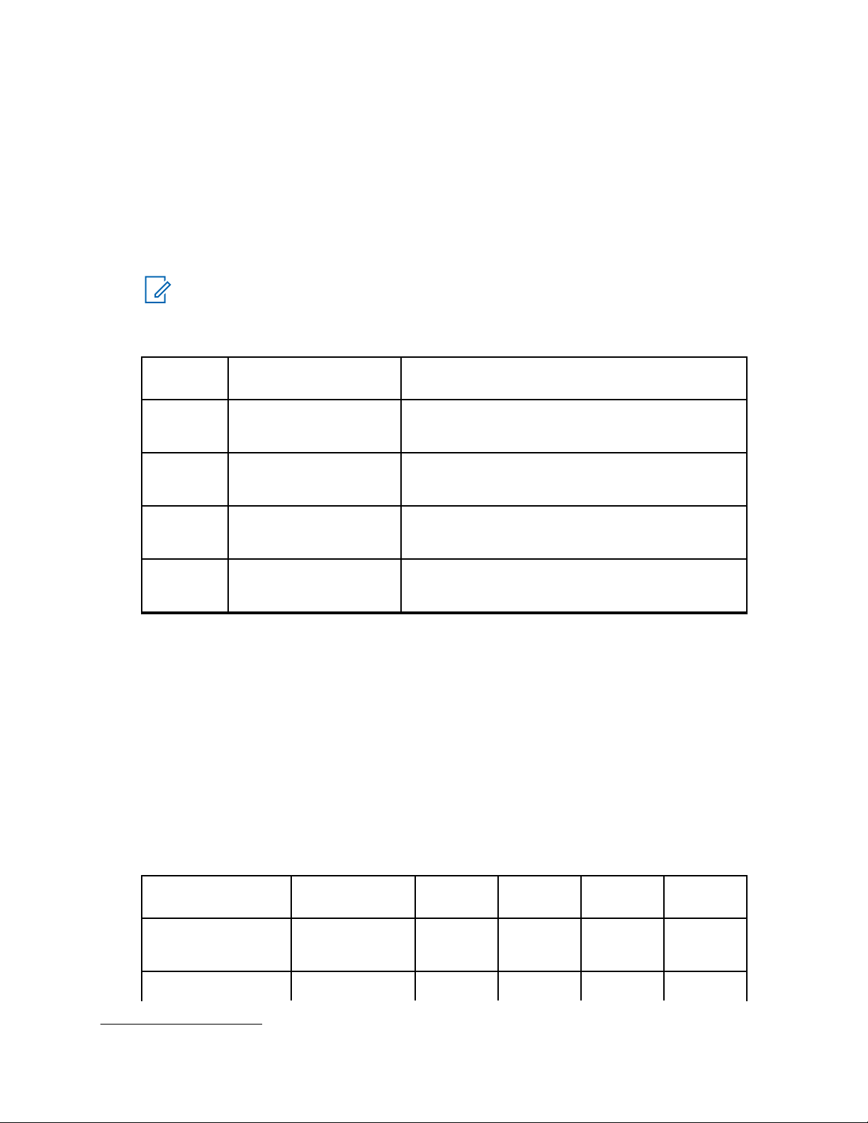
Edition Description Date
MN002211A01-AA Initial Release January 2016
MN002211A01-AB Updated Self Quieter Fre-
quencies in Specification section.
MN002211A01-AC Updated TIA Label to Non-
field replaceable in Exploded
View Parts Lists.
MN002211A01-AD Removed Footer. June 2019
MN002211A01-AE Added Limited Level 3 Servic-
ing section.
Updated Channel Capacity in
Specifications, General Specifications table.
December 2017
September 2018
July 2019
11
Page 12

MN002211A01-AE
Notations Used in This Manual
Notations Used in This Manual
Throughout the text in this publication, you will notice the use of warning, caution, and notice notations.
These notations are used to emphasize that safety hazards exist, and due care must be taken and
observed.
WARNING: WARNING indicates a potentially hazardous situation which, if not avoided, could
result in death or injury.
CAUTION: CAUTION indicates a potentially hazardous situation which, if not avoided, might
result in equipment damage.
NOTICE: NOTICE indicates an operational procedure, practice, or condition that is essential to
emphasize.
12
Page 13

Chapter 1
Introduction
1.1
Radio Description
These portable radios are available in the following frequency ranges and power levels.
Table 1: Radio Frequency Ranges and Power Levels
Frequency Band Bandwidth Power Level
VHF 136–174 MHz 1 W or 5 W
UHF 403–527 MHz 1 W or 4 W
300 Band 300–360 MHz 1 W or 4 W
350 Band 350–400 MHz 1 W or 4 W
MN002211A01-AE
Introduction
These digital radios are among the most sophisticated two-way radios available. They have a robust
design for radio users who need high performance, quality, and reliability in their daily communications.
This architecture provides the capability of supporting a multitude of legacy and advanced features
resulting in a more cost-effective two-way radio communications solution.
13
Page 14

1
2
3
4
5
6
7
8
9
10
11
12
MN002211A01-AE
Chapter 1: Introduction
1.1.1
Limited Keypad Model
This section explains the name and description of your radio buttons.
Figure 1: Limited Keypad Model
Label Item Description
1 Channel Selector Knob Rotate clockwise to increment channel and
counter-clockwise to decrement channel.
2 On/Off/Volume Knob To turn on the radio, rotate clockwise until the
knob clicks; To turn off the radio, rotate counterclockwise until the knob clicks. Rotate clockwise
to increase volume level; rotate counter-clockwise to decrease volume level.
3 LED Indicator Red, green, and amber light-emitting diodes indi-
cate operating status.
4 Push-To-Talk (PTT) Press to execute voice operations (for example,
Group Call and Private Call).
5 Microphone Allows the voice to be sent when PTT or voice
6 Side Buttons These buttons are field programmable using the
operations are activated.
Customer Programming Software (CPS).
14
Page 15

1
2
3
4
5
6
7
8
9
MN002211A01-AE
Chapter 1: Introduction
Label Item Description
7 Menu Navigation Buttons Five buttons to provide menu navigation and se-
lection interface.
8 Front Buttons These buttons are field programmable using the
CPS.
9 Liquid Crystal Display (LCD) 65 x132 full dotk-matrix grayscale display pro-
vides visual information about many radio features.
10 Speaker Outputs all tones and audio that are generated
by the radio (for example, keypad tones and
voice audio).
11 Universal Connector Interface point for all accessories to be used with
the radio. It has eight points to which specific accessories connect and be activated.
12 Antenna Provides the needed RF amplification when
transmitting or receiving.
1.1.2
Non-Keypad Model
This section explains the name and description of your radio buttons.
Figure 2: Non-Keypad Model
15
Page 16

MN002211A01-AE
Chapter 1: Introduction
Label Item Description
1 Channel Selector Knob Rotate clockwise to increment and counter-
clockwise to decrement the channel.
2 On/Off/Volume Knob To turn on the radio, rotate clockwise until the
knob clicks; To turn off the radio, rotate counterclockwise until the knob clicks. Rotate clockwise
to increase volume level; rotate counter-clockwise to decrease volume level.
3 LED Indicator Red, green, and amber light-emitting diodes indi-
cate operating status.
4 Push-To-Talk (PTT) Press to execute voice operations (for example,
Group Call and Private Call).
5 Microphone Allows the voice to be sent when PTT or voice
operations are activated.
6 Side Buttons These buttons are field programmable using the
Customer Programming Software (CPS).
7 Speaker Outputs all tones and audio that are generated
by the radio (for example, keypad tones and
voice audio).
8 Universal Connector Interface point for all accessories to be used with
the radio. It has eight points to which specific accessories connect and be activated.
9 Antenna Provides the needed RF amplification when
transmitting or receiving.
1.2
Portable Radio Model Numbering Scheme
Table 2: Portable Radio Model Numbering Scheme
Position 1 2 3 4 5 6 7 8 9 10 11 12 13 14
Typical Model
Number
Table 3: Sales Models – Description of Symbols
Position Description Value
1 Region AA = North America
MD H 0 2 J D C 9 U A 2 A N xy
AZ = Asia
LA = Latin America
MD = Europe/Middle East/Africa
2 Type of Unit H = Portable
3 Model Series 23 = DP2000 Model Series: 02
4
5 Band J = 136–174 MHz
16
Page 17

MN002211A01-AE
Chapter 1:
Position Description Value
K = 300–360 MHz
N = 350–400 MHz
R = 403–527 MHz
6 Power Level C = 1.0, 2.0, 2.5, or 3.5 W
D = 4.0–5.0 W
7 Physical Packages C = Plain Model (Low Tier)
H = Monochrome Display Limited Keypad (Mid Tier)
T = Non-Keypad (Limited Tier)
8 Channel Information 8 = Variable/Programmable Channel Spacing with unique
number of channels
9 = Variable/Programmable Channel Spacing
9 Primary Operation U = WiFi Only
W = Basic (No embedded GOB, Bluetooth, and WiFi)
Introduction
10 Primary System
Type
11 Feature Level 1 = Standard with FM
12 Version Letter N/A
13 Unique Variation N = Standard Package
14 Custom Housing 03 = GP328D
1.3
A = Conventional
B = Trunking
C = Analog Only
2 = Non-FM
3 = CSA IE CEx ATEX
4 = CQST
04 = GP338D
Model Charts
Table 4: Table Legend for Model Charts
Legend Description
X The part is compatible with checked model.
_ The latest version kit. When ordering a kit, refer to your specific kit for the
suffix number.
17
Page 18

MN002211A01-AE
Chapter 1: Introduction
1.3.1
UHF Model Chart
Table 5: DP2000e Series, UHF, 403–527 MHz Model Chart
Model/Item Description
MDH02RDH9VA1AN DP2600e, 403–527 MHz, 4 W, MO-
TOTRBO Limited Keypad Portable
MDH02RDC9VA1AN DP2400e, 403–527 MHz, 4 W, MO-
TOTRBO Non-Keypad Portable
X PMLE5076_ Back Cover Kit, MOTOTRBO Limited
Keypad Portable
X PMLE5075_ Back Cover Kit, MOTOTRBO Non-Key-
pad Portable
X PMLN7271_ Front Cover Kit Limited Keypad
X PMLN7272_ Front Cover Kit Non-Keypad
X X PMAE4068_ UHF Whip Antenna (403–527 MHz)
X X PMAE4069_ UHF Stubby Antenna (403–450 MHz)
X X PMAE4070_ UHF Stubby Antenna (440–490 MHz)
X X PMAE4071_ UHF Stubby Antenna (470–527 MHz)
X X PMAE4079_ Slim UHF Whip Antena (403–527 MHz)
1.3.2
VHF Model Chart
Table 6: DP2000e Series, VHF, 136–174 MHz Model Chart
Model/Item Description
MDH02JDH9VA1AN DP2600e, 136–174 MHz, 5 W, MO-
TOTRBO Limited Keypad Portable
MDH02JDC9VA1AN DP2400e, 136–174 MHz, 5 W, MO-
TOTRBO Non-Keypad Portable
X PMLD4734_ BC Kit, 136–174 MHz, 5 W, Limited Key-
pad Portable
X PMLD4737_ BC Kit, 136–174 MHz, 5 W, Non-Keypad
Portable
X PMLN7271_ Front Cover Kit Limited Keypad
18
X PMLN7272_ Front Cover Kit Non-Keypad
X X PMAD4117_ VHF Helical Antenna (136–155 MHz)
X X PMAD4116_ VHF HelicalAntenna (144–165 MHz)
X X PMAD4118_ VHF Helical Antenna (152–174 MHz)
X X PMAD4119_ VHF Stubby Antenna (136–148 MHz)
X X PMAD4120_ VHF Stubby Antenna (146–160 MHz)
Page 19

MN002211A01-AE
Chapter 1:
Model/Item Description
MDH02JDH9VA1AN DP2600e, 136–174 MHz, 5 W, MO-
TOTRBO Limited Keypad Portable
MDH02JDC9VA1AN DP2400e, 136–174 MHz, 5 W, MO-
TOTRBO Non-Keypad Portable
X X PMAD4121_ VHF Stubby Antenna (160–174MHz)
1.3.3
Introduction
300 MHz Model Chart
Table 7: DP2000e Series, 300 MHz, 300–360 MHz Model Chart
Model/Item Description
MDH02KDC9VA1AN DP2400e, 350–400 MHz, 4 W, MOTOTRBO Non-Keypad Portable
PMLD4799_ Back Cover Kit, MOTOTRBO Limited Keypad Portable
PMLN7272_ Front Cover Kit, MOTOTRBO Non-Keypad Portable
PMAD4135_ Stubby Antenna (320–360 MHz)
PMAD4137_ Stubby Antenna (300–337 MHz)
1.3.4
350 MHz Model Chart
Table 8: DP2000e Series, 350 MHz, 350–400 MHz Model Chart
Model/Item Description
MDH02NDC9VA1AN DP2400e, 350–400 MHz, 4 W, MOTOTRBO Non-Keypad Portable
PMLD4799_ Back Cover Kit, MOTOTRBO Limited Keypad Portable
PMLN7272_ Front Cover Kit, MOTOTRBO Non-Keypad Portable
PMAD4136_ Stubby Antenna (350–380 MHz)
PMAD4133_ Stubby Antenna (360–400 MHz)
PMAD4139_ VHF Whip Antenna (350–400 MHz)
1.4
Specifications
Table 9: General Specifications
Parameter Limited Keypad Non-Keypad
Channel Capacity 128 32
Frequency VHF: 136–174 MHz
UHF: 403–527 MHz
300 Band: 300–360 MHz
350 Band: 350–400 MHz
19
Page 20

MN002211A01-AE
Chapter 1: Introduction
Parameter Limited Keypad Non-Keypad
Dimensions (H × W × T) with
122.0 x 56.0 x 39.4 mm 122.0 x 56.0 x 39.4 mm
NiMH battery
Weight with Core Slim Li-Ion
281 g 264 g
battery
Weight with IMPRES Li-Ion
281 g 264 g
battery
Weight with Li-Ion IP57 bat-
299 g 282 g
tery
Power Supply 7.5 V nominal
Average battery life at 5/5/90 duty cycle with battery saver enabled in carrier squelch and transmitter in high power.
Core NiMH IP56 Battery (1400
mAh)
Core Li-Mn Low Temp Submersible Battery (1400 mAh)
IMPRES IP56 Li-Ion Battery
(1600 mAh)
Core Slim Li-Ion Battery (1650
mAh)
Analog: 9.5 hr
Digital: 12.0 hr
Analog: 9.5 hr
Digital: 12.0 hr
Analog: 11.0 hr
Digital: 14.5 hr
Analog: 11.5 hr
Digital: 15.0 hr
Slim IMPRES Li-Ion Battery
(2050 mAh)
IMPRES Li-Ion Battery (2250
mAh)
IMPRES TIA4950 Hi-Cap LiIon Battery (2900 mAh)
IMPRES Ultra Hi-Cap Li-Ion
Battery (3000 mAh)
Analog: 14.0 hr
Digital: 18.5 hr
Analog: 16.0 hr
Digital: 20.5 hr
Analog: 20.0 hr
Digital: 26.5 hr
Analog: 21.0 hr
Digital: 27.5 hr
NOTICE:
Weight can have 5% margin of error.
Limited Keypad Model is not applicable to 300 Band.
Table 10: Receiver Specifications
Parameter Limited Keypad and Non-Keypad
Frequency VHF: 136–174 MHz
UHF: 403–527 MHz
300 Band: 300–360 MHz
350 Band: 350–400 MHz
Channel Spacing 12.5 kHz/20 kHz/25 kHz
20
1
Page 21

Parameter Limited Keypad and Non-Keypad
MN002211A01-AE
Chapter 1:
Introduction
Frequency Stability (-30 °C to
±0.5 ppm
+60 °C)
Analog Sensitivity (12 dB SI-
0.26 µV (0.15 µV typical)
NAD)
Digital Sensitivity (5% BER) 0.22 µV (0.13 µV typical)
Intermodulation (TIA603D) 70 dB
Adjacent Channel Selectivity TIA603A: 60 dB @ 12.5 kHz, 70 dB @ 20/25 kHz
TIA603D: 45 dB @ 12.5 kHz, 70 dB @ 20/25 kHz
Spurious Rejection (TIA603D) 70 dB
Rated Audio 500 mW
Audio Distortion @ Rated Au-
5% (3% typical)
dio
Hum and Noise -40 dB @ 12.5 kHz
-45 dB @ 20/25 kHz
1
Audio Response TIA603D
Conducted Spurious Emission
-57 dBm
(TIA603C/D)
1
1
Table 11: Transmitter Specifications
Parameter Limited Keypad and Non-Keypad
Frequency VHF: 136–174 MHz
UHF: 403–527 MHz
300 Band: 300–360 MHz
350 Band: 350–400 MHz
Channel Spacing 12.5/20/25 kHz
Frequency Stability (-30 °C to
±0.5 ppm
2
+60 °C)
Power Output (Low Power) VHF/UHF: 0.5 W
300/350 Band: 1 W
Power Output (High Power) VHF: 5 W
UHF/300 Band/350 Band
: 4 W
Modulation Limiting ±2.5 kHz @ 12.5 kHz
±5.0 kHz @ 25 kHz
±4.0kHz @ 20 kHz
2
FM Hum and Noise -40 dB @ 12.5 kHz
1
350 Band does not support 20 kHz.
2
350 Band does not support 20 kHz.
21
Page 22

MN002211A01-AE
Chapter 1: Introduction
Parameter Limited Keypad and Non-Keypad
-45 dB @ 20/25 kHz
2
Conducted/Radiated Emission -36 dBm < 1 GHz
-30 dBm > 1 GHz
Adjacent Channel Power 60 dB @ 12.5 kHz
70 dB @ 20/25 kHz
2
Audio Response TIA603D
Audio Distortion 3%
FM Modulation 12.5 kHz: 11K0F3E
25 kHz: 16K0F3E
4FSK Digital Modulation 12.5kHz Data: 7K60F1D and 7K60FXD
12.5kHz Voice: 7K60F1E and 7K60FXE
Digital Vocoder Type AMBE+2
™
Digital Protocol ETSI-TS102361-1
ETSI-TS102361-2
ETSI-TS102361-3
NOTICE: Limited Keypad Model is not applicable to 300 Band.
Conforms to:
• ETSI TS 102 361 (Parts 1, 2, and 3) - ETSI DMR Standard
•
ETSI EN 300 086 - ETSI RF Specifications (Analog)
• ETSI EN 300 113 - ETSI RF Specifications (Digital)
• 1999/5/EC (R&TTE - Radio and Telecommunications Terminal Equipment)
• 2011/65/EU (RoHS 2 - Banned Substances)
• 2012/19/EU (WEEE - Waste Electrical and Electronic Equipment)
• 94/62/EC (Packaging and Packaging Waste)
• Radio meets applicable regulatory requirements.
Table 12: Self-Quieter Frequencies
UHF (MHz) VHF (MHz) 300 Band (MHz) 350 Band (MHz)
403.2 +/-10KHz 136.8 +/-10KHz 307.2 +/-10KHz 360 +/-10KHz
408 +/-10KHz 139.2 +/-10KHz 312 +/-10KHz 364.8 +/-10KHz
410.4 +/-10KHz 144 +/-10KHz 319.2 +/-10Khz 369.6 +/-10KHz
422.4 +/-10KHz 148.8 +/-10KHz 324 +/-10Khz 384 +/-10KHz
427.2 +/-10KHz 153.6 +/-10KHz 336 +/-10KHz 396 +/-10KHz
432 +/-10KHz 158.4 +/-10KHz 340.8 +/-10KHz -
446.4 +/-10KHz 160 +/-10KHz 345.6 +/-10KHz -
22
Page 23

Chapter 1:
UHF (MHz) VHF (MHz) 300 Band (MHz) 350 Band (MHz)
456 +/-10KHz 163.2 +/-10KHz 360 +/-10KHz -
460.8 +/-10KHz 168 +/-10KHz - -
465.6 +/-10KHz 172.03 +/-10KHz - -
468 +/-10KHz 172.8 +/-10KHz - -
480 +/-10KHz - - -
499.2 +/-10KHz - - -
501.6 +/-10KHz - - -
504 +/-10KHz - - -
508.8 +/-10KHz - - -
519.25 +/-10KHz - - -
Table 13: Military Standards
MN002211A01-AE
Introduction
Applicable
MILSTD
Low
Pressure
High
Temperature
Low
Temperature
Temperature
Shoc
k
810C 810D 810E 810F 810G
Meth
ods
Procedures
Meth
ods
Procedures
Meth
ods
Procedures
Meth
ods
Procedures
Meth
ods
Procedures
500.1 Ⅰ 500.2 Ⅱ 500.3 Ⅱ 500.4 Ⅱ 500.5 Ⅱ
501.1 Ⅰ,
Ⅱ
501.2 Ⅰ/A1
,
Ⅱ/A1
501.3 Ⅰ/A1
,
Ⅱ/A1
501.4 Ⅰ/
Hot,
Ⅱ/H
501.5 Ⅰ/A1
,
Ⅱ/A1
ot
502.1 Ⅰ 502.2 Ⅰ/C
3,
Ⅱ/C
1
502.3 Ⅰ/C
3,
Ⅱ/C
1
502.4 Ⅰ/C
3,
Ⅱ/C
1
502.5 Ⅰ/C
3,
Ⅱ/C
1
503.1 Ⅰ 503.2 A1/C3503.3 A1/C3503.4 Ⅰ 503.5 Ⅰ-C
Solar
505.1 Ⅱ 505.2 Ⅰ/
Radiation
Rain 506.1 Ⅰ,
Ⅱ
Hu-
507.1 Ⅱ 507.2 Ⅱ/
midity
Hot-
Dry
506.2 Ⅰ,
Ⅱ
Hot-
Humid
505.3 Ⅰ/
Hot-
Dry
506.3 Ⅰ,
Ⅱ
507.3 Ⅱ/
Hot-
Humid
505.4 Ⅰ/
505.5 Ⅰ/A1
Hot-
Dry
506.4 Ⅰ,
Ⅲ
506.5 Ⅰ,
Ⅲ
507.4 – 507.5 Ⅰ/
Hot-
Humid
23
Page 24

MN002211A01-AE
Chapter 1:
Introduction
Applicable
MILSTD
Salt
810C 810D 810E 810F 810G
Meth
ods
Procedures
Meth
ods
Procedures
Meth
ods
Procedures
509.1 Ⅰ 509.2 Ⅰ 509.3 Ⅰ 509.4 – 509.5 –
fog
Dust 510.1 Ⅰ,
Ⅱ
Vibration
514.2 Ⅷ/F,
Curv
e-W,
Ⅺ
Shock516.2 Ⅰ,
Ⅱ
510.2 Ⅰ,
Ⅱ
514.3 Ⅰ/
Cat1
0, Ⅱ/
Cat3
516.3 Ⅰ,
Ⅳ
510.3 Ⅰ,
Ⅱ
514.4 Ⅰ/
Cat1
0, Ⅱ/
Cat3
516.4 Ⅰ,
Ⅳ
Table 14: Environmental Specifications
Parameter Specifications
Operating Temperature -30 °C to +60 °C
Meth
ods
Procedures
510.4 Ⅰ,
Ⅱ
514.5 Ⅰ/
Cat2
4, Ⅱ/
Cat5
516.5 Ⅰ,
Ⅳ
Meth
ods
Procedures
510.5 Ⅰ,
Ⅱ
514.6 Ⅰ/
Cat2
4, Ⅱ/
Cat5
516.6 Ⅰ,
Ⅳ
Storage Temperature -40 °C to +85 °C
Thermal Shock Per MIL-STD
Humidity Per MIL-STD
ESD IEC 61000-4-2 Level 4
Water Intrusion IEC 60529 -IP67
Packaging Test MIL-STD 810D and E
3
Operating temperature specification with Li-Ion battery is -10 °C to +60 °C. Operating temperature specification with NiMH battery is -20 °C to +60 °C.
24
Page 25

MN002211A01-AE
Test Equipment and Service Aids
Chapter 2
Test Equipment and Service Aids
This chapter lists the recommended test equipment and service aids, as well as information on field
programming equipment that can be used in servicing and programming Motorola Solutions radios.
2.1
Recommended Test Equipment
The list of equipment contained in the following table includes most of the standard test equipment
required.
Table 15: Test Equipment
Equipment Characteristics Example Application
Service
Monitor
Digital RMS
Multimeter
RF Signal
Generator
Oscilloscope
Power Meter
and Sensor
4
4
4
Can be used as a substitute.
100 µV to 300 V Fluke 179 (www.fluke.com) or
5 Hz to 1 MHz
10 ㏁ Impedance
100 MHz to 1 GHz Agilent N5181A (www.agi-
-130 dBm to +10 dBm
FM Modulation: 0 kHz
to 10 kHz
Audio Frequency: 100
Hz to 10 kHz
2 Channel Tektronix TDS1001b
50 MHz Bandwidth
5 mV/div to 20 V/div
5% Accuracy Bird 43 Thruline Watt Meter
4
100 MHz to 500 MHz
50 W
Aeroflex 3920 (www.aero-
flex.com) or equivalent
equivalent
lent.com), Ramsey
RSG1000B (www.ramseye-
lectronics.com), or equivalent
(www.tektronix.com)
or equivalent
(www.bird-electronic.com) or
equivalent
Frequency/deviation meter
and signal generator for
wide-range troubleshooting
and alignment.
AC/DC voltage and
current measurements. Audio voltage measurements.
Receiver measurements
Waveform measurements
Transmitter power output
measurements
RF Millivoltmeter
Power Supply
4
Can use Service Monitor as substitute.
100 mV to 3 V RF Boonton 92EA
10 kHz to 1 GHz
0 V to 32 V B&K Precision 1790
0 A to 20 A
RF level measurements
(www.boonton.com) or equivalent
Voltage supply
(www.bkprecision.com)
or equivalent
25
Page 26

MN002211A01-AE
Chapter 2: Test Equipment and Service Aids
2.2
Service Aids
The following table lists the service aids recommended for working on the radio. While all of these
items are available from Motorola Solutions, most are standard workshop equipment items, and any
equivalent item capable of the same performance may be substituted for the item listed.
Table 16: Service Aids
Motorola
Solutions
Part No.
RLN4460_ Portable Test Set Enables connection to the audio/accessory jack.
GMVN5141_ CPS on CD-ROM Allows servicer to program radio parameters, tune
PMKN4115_ Portable Programming Cable This cable connects the radio to a USB port for ra-
PMKN4117_ Portable Programming, Testing,
Description Application
Allows switching for radio testing.
and troubleshoot radios.
dio programming and data applications.
This cable connects the radio to a USB port for ra-
and Alignment Cable
dio programming, testing, and alignment.
NOTICE:
• This cable does not support external
PTT using Testbox.
This cable does not auto route to ex-
•
ternal Audio path once the cable is attached.
• All test instructions will require
through software tool (for example,
CPS, Tuner, and more.)
PMNN4428_ 7.5 V Universal Battery Elimina-
tor
PMLN6154_ RF Adaptor Adapts radio antenna port to BC cabling of test
PMLN6201_ RF Adaptor Holder Holds RF adaptor in place.
PMLN6422_ SMA RF Cable RF cable with SMA and N-type connector.
1185937A01 Grease Acts to lubricate parts.
TL000013A01Chassis and Knob Opener Removes chassis from the front housing.
NLN9839_ Vacuum Pump Kit Allows servicer to test for leakages.
NTN4265_ Pressure Pump Kit Allows servicer to locate leakages.
5871134M01 Connector Fitting This connector allows the vacuum hose to be con-
3271133M01 Fitting Seal This seal secures the connector fitting to the radio
26
Connects to radio by using battery eliminator cable.
equipment.
nected to the radio chassis.
chassis.
Page 27

MN002211A01-AE
Chapter 2: Test Equipment and Service Aids
2.3
Programming, Testing, and Alignment Cable
Programming, Testing, and Alignment Cable and Side Connector are required in servicing and
programming radios.
27
Page 28

#13
#25 #14
#1
P1
P4
#2
#4
#6
#8
#1
#3
#5
#7
P3
#1#4
P2
MN002211A01-AE
Chapter 2: Test Equipment and Service Aids
Figure 3: Programming, Testing, and Alignment Cable
Table 17: Pin Configuration of Side Connector
CONNECTION
P1 P2 P3
Pin Pin Pin Function
- 1 1 VCC (5 V)
28
Page 29

P1 P2 P3
1
3
5
7
4
2
6
8
Pin Pin Pin Function
- 3 5 Data+
- 2 4 Data-
16 4 8 Ground
1 and 5 - 2 External Speaker+
2 and 7 - 3 External Speaker-
17 - 6 External Mic+
16 - 7 External Mic-
Figure 4: Pin Layout of Side Connector
MN002211A01-AE
Chapter 2: Test Equipment and Service Aids
CONNECTION
29
Page 30

MN002211A01-AE
Chapter 3: Transceiver Performance Testing
Chapter 3
Transceiver Performance Testing
These radios meet published specifications through their manufacturing process by utilizing highaccuracy laboratory-quality test equipment.
The recommended field service equipment approaches the accuracy of the manufacturing equipment
with few exceptions. This accuracy must be maintained in compliance with the calibration schedule
recommended by the manufacturer.
Although these radios function in digital and analog modes, all testing is done in analog mode.
3.1
Setup
Supply voltage is provided using a 7.5 VDC power supply.
procedures is connected as shown in the Radio Tuning Setup chapter.
WARNING: Do NOT use any form of connector, for example wires, crocodile clips, and probes,
to supply voltage to the radio, other than the Motorola Solutions approved battery eliminator.
Initial equipment control settings must be as indicated in the following table:
Table 18: Initial Equipment Control Settings
Service Monitor Power Supply Test Set
Monitor Mode: Power Monitor Voltage: 7.5 Vdc Speaker set: A
RF Attn: -70 DC on/standby:
AM, CW, FM: FM Volt Range: 10 V PTT: OFF
Oscilloscope Source: Mod
Oscilloscope Horizontal: 10 ms/Div
Oscilloscope Vertical: 2.5 kHz/Div
Oscilloscope Trigger: Auto
Monitor Image: Hi
Monitor Bandwidth: Narrow
Monitor Squelch: Middle setting
Monitor Vol: 1/4 setting
The equipment required for alignment
Speaker/load:
Standby
Current: 2.5 A
Speaker
3.1.1
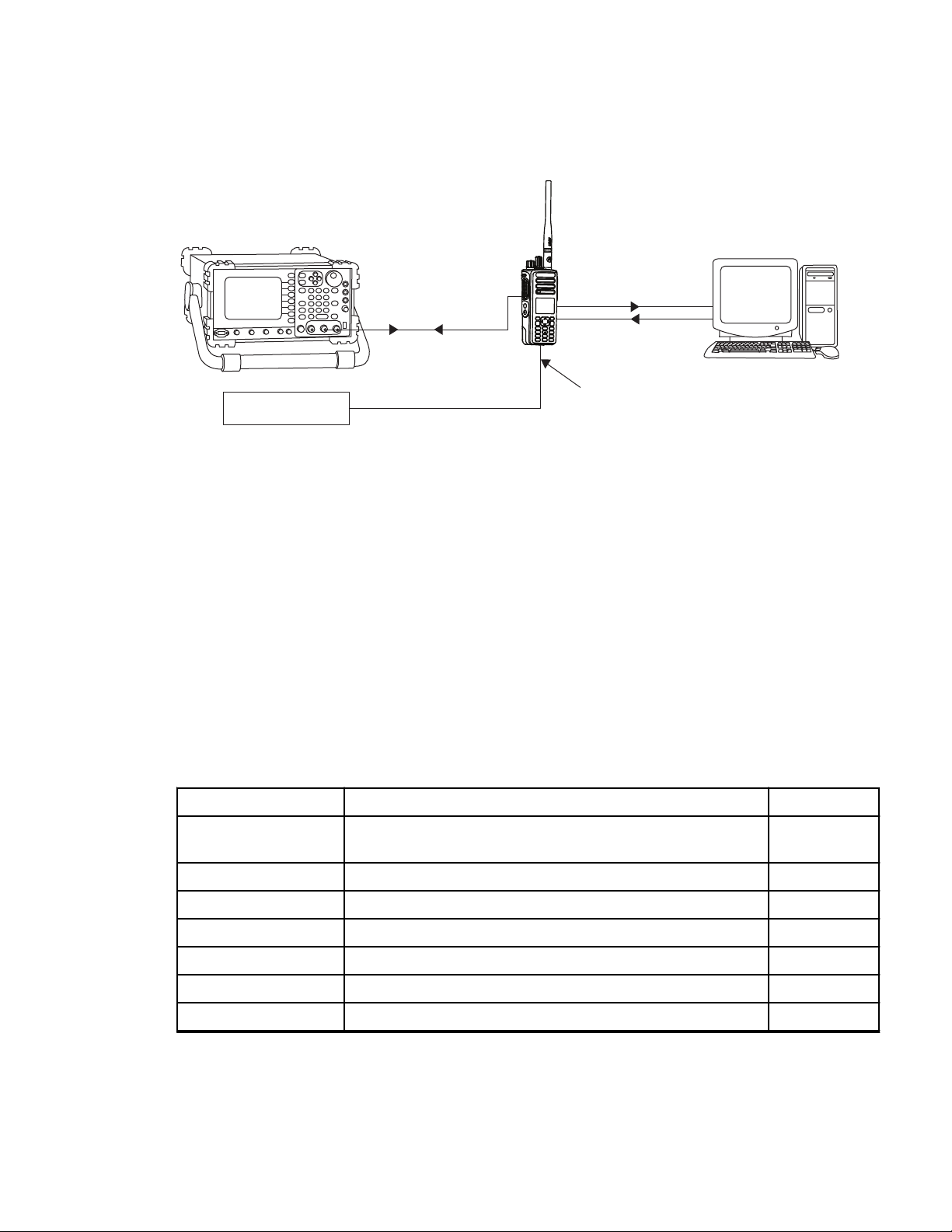
Setting Up DMR Transmitter and Receiver Test
Procedure:
1 Connect the Programming cable to the radio and computer.
2 Remove the RF plug.
3 Connect the RF antenna adaptor to the 50 Ω RF Input/Output port of the radio.
30
Page 31
T/R Port
Power Supply
Ant. Input / Output
Programming Cable
Modulated RF Test
Signal / Tx
modulated RF Signal
Battery Eliminator
MN002211A01-AE
Chapter 3: Transceiver Performance Testing
4 Connect the other end of the RF antenna adaptor to the T/R port of the Radio Test Set 3920
using the RF cable shown in the following figure.
Figure 5: DMR Radio Transmitter and Receiver Testing Setup
See RF Plug Disassembly on page 47 for RF Plug Removal and RF Adaptor Insertion.
3.2
Display Model Test Mode
3.2.1
Entering Display Radio Test Mode
Procedure:
1 Turn the radio on.
2 Within 10 seconds after Self-Test is complete, press Side Button 2 five times in succession.
The radio beeps and shows a series of displays regarding various version numbers and
subscriber-specific information. The displays are described in the following table.
Table 19: Front Panel Access Test Mode Displays
Name of Display Description Appears
Service Mode The literal string indicates the radio has entered test
mode.
Host Version The version of host firmware. Always
DSP Version The version of DSP firmware. Always
Model Number The radio model number as programmed in the codeplug. Always
MSN The radio serial number as programmed in the codeplug. Always
FLASHCODE The FLASH codes as programmed in the codeplug. Always
RF Band The radio band. Always
Always
31
Page 32
MN002211A01-AE
Chapter 3: Transceiver Performance Testing
NOTICE: The radio stops at each display for 2 seconds before moving to the next
information display. If the information cannot fit into one line, the radio display scrolls
automatically character by character after 1 second to view the whole information. If the
button is pressed before the last information is displayed, the radio suspends the
Left
information display until the user presses the Right button to resume the information
display. The last display shows RF Test Mode.
3.2.2
RF Test Mode
When the radio is operating in its normal environment, the radio microcontroller controls the RF
channel selection, transmitter key-up, and receiver muting, according to the customer codeplug
configuration.
However, when the unit is on the bench for testing, alignment, or repair, it must be removed from its
normal environment with a special routine, called Test Mode or air test.
3.2.2.1
Testing RF Channel Selections
Prerequisites: In RF Test Mode, the first line of your radio displays RF Test and power level icon.
And the second line of your radio displays the test environment, channel number, and channel spacing.
The default test environment is CSQ.
5
Procedure:
1 Each short press of Side Button 2 changes the test environment (CSQ->TPL->DIG->USQ
->CSQ).
NOTICE: DIG is digital mode and other test environments are analog mode as described
in the following table.
Table 20: Test Environments
No. of
Description Function
Beeps
1 Carrier Squelch (CSQ) RX: if carrier detected
TX: mic audio
2 Tone Private-Line
(TPL)
RX: unsquelch if carrier and tone detected
TX: mic audio + tone
3 Digital Mode (DIG) RX: if carrier detected
TX: mic audio
4 Unsquelch (USQ) RX: constant unsquelch
TX: mic audio
The radio beeps once when radio toggles to CSQ, beeps twice for TPL, beeps three times for
DIG, and beeps four times for USQ.
5
Only for radios with display.
32
Page 33
MN002211A01-AE
Chapter 3: Transceiver Performance Testing
2 Each short press of Side Button 1 toggles the channel spacing between 25 kHz, 12.5 kHz, and
20 kHz.
The radio beeps once when radio toggles to 20 kHz, beeps twice for 25 kHz, and beeps three
times for 12.5 kHz.
3 Turn Channel Knob to change the test channel from 1 to 14.
See Table 21: Test Frequencies on page
33 for test channel descriptions.
The radio beeps in each position.
Table 21: Test Frequencies
Channel Selector
Switch Position
1 Low Power
9 High Power
2 Low Power
10 High Power
3 Low Power
11 High Power
4 Low Power
12 High Power
5 Low Power
13 High Power
6 Low Power
14 High Power
7 Low Power
15 High Power
Test Channel UHF VHF 300
Band
TX#1 or #9
RX#1 or #9
TX#2 or #10
RX#2 or #10
TX#3 or #11
RX#3 or #11
TX#4 or #12
RX#4 or #12
TX#5 or #13
RX#5 or #13
TX#6 or #14
RX#6 or #14
TX#7 or #15
RX#7 or #15
403.15
403.15
423.25
423.25
444.35
444.35
465.45
465.45
485.55
485.55
506.65
506.65
526.75
526.75
136.075
136.075
142.575
142.575
146.575
146.575
155.575
155.575
161.575
161.575
167.575
167.575
173.975
173.975
300.025
300.025
308.525
308.525
317.025
317.025
325.525
325.525
334.025
334.025
342.525
342.525
351.025
351.025
350
Band
350.025
350.025
357.525
357.525
364.525
364.525
371.525
371.525
378.525
378.525
385.525
385.525
392.525
392.525
8 Low Power
16 High Power
TX#8 or #16
RX#8 or #16
Table 22: Transmitter Performance Checks
Test
Name
Reference Frequency
Communications Analyzer
Mode: PWR MON
Fourth channel test
frequency
6
Monitor: Frequency error
Input at RF In/Out
6
See Table 21: Test Frequencies
on page 33
527.00
527.00
174.000
174.000
359.925
359.925
Radio Test Set Comments
Test
Mode,
Test
Channel
4 carrier
PTT to
continuously
transmit.
Frequency error to be:
±68 Hz for VHF
±150 Hz for 300 Band
squelch
±175 Hz for 350 Band
.
399.925
399.925
33
Page 34

MN002211A01-AE
Chapter 3: Transceiver Performance Testing
Test
Name
Communications Analyzer
Radio Test Set Comments
±201 Hz for UHF
Power RF As above As above As above Low Power:
0.9–1.5 W
(UHF/VHF/300
Band/350 Band)
High Power:
4.0–4.8 W (UHF/300
Band/350 Band
5.0–6.0 W (VHF)
Voice
Modulation
Mode: PWR MON
Fourth channel test
frequency
6
As above As above,
meter selector to
mic
Deviation:
≥ 4.0 kHz but ≤ 5.0 kHz
(25 kHz Ch Sp).
atten to -70, input to RF
In/Out
Monitor: DVM: AC Volts
Set 1 kHz Mod Out lev-
el for 0.025 Vrms at
test set,
80 mVrms at AC/DC
test set jack
)
Internal
Voice
Modulation
Mode: PWR MON
Fourth channel test
frequency
6
atten to -70, input to RF
In/Out
TPL
Modulation
As above
Fourth channel test
frequency
6
BW to narrow
Table 23: Receiver Performance Checks
Test
Name
Reference Frequency
Communications Analyzer
Mode: PWR MON
Fourth channel test
frequency
6
Monitor: Frequency error
Test
Mode,
Test
Channel
4 carrier
squelch
output at
Remove
modulation input
Press PTT switch on
radio. Say "four" loudly
into the radio mic.
Measure
deviation:
≥ 4.0 kHz but ≤ 5.0 kHz
(25 kHz Ch Sp)
antenna
Test
Mode,
Test
As above Deviation:
≥500 Hz but ≤1000Hz
(25 kHz Ch Sp).
Channel
4
TPL
Radio Test Set Comments
Test
Mode,
Test
Channel
4 carrier
PTT to
continuously
transmit.
Frequency error to be:
±68 Hz for VHF
±150 Hz for 300 Band
squelch
34
Page 35

Chapter 3:
MN002211A01-AE
Transceiver Performance Testing
Test
Name
Communications Analyzer
Input at RF In/Out
Rated
Audio
Mode: GEN
Output level: 1.0 mV
RF
Sixth channel test
frequency
6
Mod: 1 kHz tone at
3 kHz deviation
Monitor: DVM: AC Volts
Distortion As above, except dis-
tortion
Sensitivity (SINAD)
As above, except SINAD, lower the RF level for
12 dB SINAD.
Noise
Squelch
RF level set to 1 mV
RF
Threshold
(only radios with
conventional
system
need to
be tested.)
As above, except
change frequency to a
conventional system.
Raise RF level from
zero until radio un-
squelches.
Radio Test Set Comments
output at
antenna. ±175 Hz for 350 Band
±201 Hz for UHF
Test
Mode
, Test
Meter selector to
Audio PA
Set volume
control to 2.83 Vrms
Channel
6 carrier
squelch
As above As above Distortion <3.0%
As above Nil RF input to be <0.35
μV
As above Meter se-
lection to
Set volume
control to 2.83 Vrms
Audio PA,
speaker/
load to
speaker
Out of
Test
Mode; select a
conven-
As above Unsquelch to occur at
<0.25 μV.
Preferred SINAD =
6–8 dB
tional
system.
3.2.3
Display Test Mode
Procedure:
1 Press and hold Side Button 1 to enter display test mode.
2 Upon any button or key press, the LCD displays the growing horizontal bars. Press any button
until the LCD display turns black and change to vertical bars. Press any button until LCD display
full screen black and change to icon display.
The LCD displays the following icons:
• RSSI (with full bar)
Monitor
•
35
Page 36

MN002211A01-AE
Chapter
• Tone disabled
• Priority-two channel scan
Unread message
•
• Emergency
• Talkaround
• Battery strength indicator (with full bar)
The LCD display become clear and consequently display the rest of the icons, high-power level icon
(H), companding icon, option board icon, and secure operation icon upon any button/key press.
3.2.4
Transceiver Performance Testing
3:
LED Test Mode
Procedure:
1 Press and hold Side Button 1 after Display Test Mode.
The radio beeps once and displays LED Test Mode.
2 Press any button/key.
The red LED lights up and the radio displays Red LED On.
3 Press any button/key.
The red LED is turned off. The green LED lights up and the radio displays Green LED On.
4 Press any button/key.
The green LED is turned off. The radio lights up both LEDs up while displaying Both LEDs On.
The orange LED lights up.
3.2.5
Backlight Test Mode
Procedure:
Press and hold Side Button 1 after LED Test Mode.
The radio beeps once and displays Backlight Test Mode.
The radio turns on both LCD and keypad backlight.
3.2.6
Speaker Tone Test Mode
Procedure:
Press and hold Side Button 1 after Backlight Test Mode.
The radio beeps once and displays Speaker Tone Test Mode.
The radio generates a 1 kHz tone with the internal speaker.
36
Page 37

Rem. Capacity100%
Chapter 3: Transceiver Performance Testing
3.2.7
Earpiece Tone Test Mode
Procedure:
1 Connect the external accessory to the radio.
2 Press and hold Side Button 1 after Speaker Tone Test Mode.
The radio beeps once and displays Earpiece Tone Test Mode.
The radio generates a 1 kHz tone from the earpiece.
3.2.8
Audio Loopback Earpiece Test Mode
Procedure:
Press and hold Side Button 1 after the Earpiece Tone Test Mode.
The radio beeps once and displays Audio Loopback Earpiece Test Mode.
The radio routes any audio on the external mic to the earpiece.
MN002211A01-AE
3.2.9
Battery Check Test Mode
Procedure:
Press and hold Side Button 1 after Audio Loopback Earpiece Test Mode.
The radio beeps once and momentarily displays Battery Check Test Mode.
The radio displays the following:
Figure 6: Battery Check Test Mode Display
37
Page 38

MN002211A01-AE
Chapter 3: Transceiver Performance Testing
3.2.10
Button/Knob/PTT Test Mode
Any key press causes the test to advance from one step to the next.
Table 24: Button/Knob/PTT Checks
Action Result
Press and hold Side Button 1. The radio displays Button Test (line 1).
The radio beeps once.
Rotate the Volume Knob. 2/1 through 2/255 appears.
The radio beeps at each position.
Rotate the Channel Knob clockwise. 4/1 appears.
The radio beeps at each position.
Rotate the Channel Knob counterclockwise. 4/-1 appears.
The radio beeps at each position.
Press Side Button 1. 96/1 appears.
The radio beeps.
Release the button. 96/0 appears.
The radio beeps.
Press Side Button 2. 97/1 appears.
The radio beeps.
Release the button. 97/0 appears.
The radio beeps.
Press the PTT
Release the button. 1/0 appears.
Table 25: Keypad Checks
Action Result
Press the P1 button. 160/1 appears.
Release the button. 160/0 appears.
Press the P2 button. 161/1 appears.
button. 1/1
The radio beeps.
The radio beeps.
The radio beeps.
The radio beeps.
The radio beeps.
appears.
Release the button. 161/0 appears.
The radio beeps.
Press the MENU button. 85/1 appears.
The radio beeps.
38
Page 39
Chapter 3: Transceiver Performance Testing
Action Result
Release the button. 139/0 appears.
The radio beeps.
MN002211A01-AE
Press the BACK button. 129/1
The radio beeps.
Release the button. 129/0 appears.
The radio beeps.
Press the Left button. 128/1 appears.
The radio beeps.
Release the button. 128/0 appears.
The radio beeps.
Press the Right
Release the button. 130/0 appears.
Press the OK button. 85/1 appears.
Release the button. 85/0 appears.
3.3
button. 130/1
The radio beeps.
The radio beeps.
The radio beeps.
The radio beeps.
appears.
appears.
Non-Display Model Test Mode
3.3.1
Entering Non-Display Radio Test Mode
Procedure:
1 Turn the radio on.
2 Within 10 seconds after Self-Test is complete, press Side Button 2 five times in succession.
The radio beeps.
3.3.2
RF Test Mode
When the radio is operating in its normal environment, the radio microcontroller controls the RF
channel selection, transmitter key-up, and receiver muting, according to the customer codeplug
configuration.
However, when the unit is on the bench for testing, alignment, or repair, it must be removed from its
normal environment with a special routine, called Test Mode or air test.
39
Page 40
MN002211A01-AE
Chapter 3: Transceiver Performance Testing
3.3.2.1
Testing RF Channel Selections
Prerequisites: In RF Test Mode, the first line of your radio displays RF Test and power level icon.
And the second line of your radio displays the test environment, channel number, and channel spacing.
The default test environment is CSQ.
Procedure:
1 Each short press of Side Button 2 changes the test environment (CSQ->TPL->DIG->USQ
->CSQ).
NOTICE: DIG is digital mode and other test environments are analog mode as described
in the following table.
Table 26: Test Environments
7
No. of
Description Function
Beeps
1 Carrier Squelch (CSQ) RX: if carrier detected
TX: mic audio
2 Tone Private-Line
(TPL)
RX: unsquelch if carrier and tone detected
TX: mic audio + tone
3 Digital Mode (DIG) RX: if carrier detected
TX: mic audio
4 Unsquelch (USQ) RX: constant unsquelch
TX: mic audio
The radio beeps once when radio toggles to CSQ, beeps twice for TPL, beeps three times for
DIG, and beeps four times for USQ.
2 Each short press of Side Button 1 toggles the channel spacing between 25 kHz, 12.5 kHz, and
20 kHz.
The radio beeps once when radio toggles to 20 kHz, beeps twice for 25 kHz, and beeps three
times for 12.5 kHz.
3 Turn Channel Knob to change the test channel from 1 to 14.
See Table 27: Test Frequencies on page
40 for test channel descriptions.
The radio beeps in each position.
Table 27: Test Frequencies
Channel Selector
Switch Position
1 Low Power
9 High Power
2 Low Power TX#2 or #10 423.25 142.575 308.525 357.525
7
Only for radios with display.
40
Test Channel UHF VHF 300
Band
TX#1 or #9
RX#1 or #9
403.15
403.15
136.075
136.075
300.025
300.025
350
Band
350.025
350.025
Page 41
MN002211A01-AE
Chapter 3: Transceiver Performance Testing
Channel Selector
Test Channel UHF VHF 300
Switch Position
10 High Power
3 Low Power
11 High Power
4 Low Power
12 High Power
5 Low Power
13 High Power
6 Low Power
14 High Power
7 Low Power
15 High Power
8 Low Power
16 High Power
RX#2 or #10 423.25 142.575 308.525 357.525
TX#3 or #11
RX#3 or #11
TX#4 or #12
RX#4 or #12
TX#5 or #13
RX#5 or #13
TX#6 or #14
RX#6 or #14
TX#7 or #15
RX#7 or #15
TX#8 or #16
RX#8 or #16
Table 28: Transmitter Performance Checks
444.35
444.35
465.45
465.45
485.55
485.55
506.65
506.65
526.75
526.75
527.00
527.00
146.575
146.575
155.575
155.575
161.575
161.575
167.575
167.575
173.975
173.975
174.000
174.000
Band
317.025
317.025
325.525
325.525
334.025
334.025
342.525
342.525
351.025
351.025
359.925
359.925
350
Band
364.525
364.525
371.525
371.525
378.525
378.525
385.525
385.525
392.525
392.525
399.925
399.925
Test
Name
Reference Frequency
Communications Analyzer
Mode: PWR MON
Fourth channel test
frequency
8
Monitor: Frequency error
Input at RF In/Out
Radio Test Set Comments
Test
Mode,
Test
Channel
4 carrier
PTT to
continuously
transmit.
Frequency error to be:
±68 Hz for VHF
±150 Hz for 300 Band
squelch
±175 Hz for 350 Band
±201 Hz for UHF
Power RF As above As above As above Low Power:
0.9–1.5 W
(UHF/VHF/300
Band/350 Band)
High Power:
4.0–4.8 W (UHF/300
/350 Band)
Band
5.0–6.0 W (VHF)
Voice
Modulation
Mode: PWR MON
Fourth channel test
frequency
8
As above As above,
meter selector to
mic
Deviation:
≥ 4.0 kHz but ≤ 5.0 kHz
(25 kHz Ch Sp).
8
See Table 27: Test Frequencies
on page 40
.
41
Page 42

MN002211A01-AE
Chapter 3: Transceiver Performance Testing
Test
Name
Internal
Voice
Modulation
TPL
Modulation
Communications Analyzer
atten to -70, input to RF
In/Out
Monitor: DVM: AC Volts
Set 1 kHz Mod Out lev-
el for 0.025 Vrms at
test set,
80 mVrms at AC/DC
test set jack
Mode: PWR MON
Fourth channel test
frequency
8
atten to -70, input to RF
In/Out
As above
Fourth channel test
frequency
8
BW to narrow
Radio Test Set Comments
Test
Mode,
Test
Channel
4 carrier
squelch
output at
Remove
modulation input
Press PTT switch on
radio. Say "four" loudly
into the radio mic.
Measure
deviation:
≥ 4.0 kHz but ≤ 5.0 kHz
(25 kHz Ch Sp)
antenna
Test
Mode,
Test
As above Deviation:
≥500 Hz but ≤
(25 kHz Ch Sp).
Channel
4
TPL
1000Hz
Table 29: Receiver Performance Checks
Test
Name
Reference Frequency
Communications Analyzer
Mode: PWR MON
Fourth channel test
frequency
8
Monitor: Frequency error
Input at RF In/Out
Rated
Audio
Mode: GEN
Output level: 1.0 mV
RF
Sixth channel test
frequency
8
Mod: 1 kHz tone at
3 kHz deviation
Monitor: DVM: AC Volts
Distortion As above, except dis-
tortion
Radio Test Set Comments
Test
Mode,
Test
Channel
4 carrier
PTT to
continuously
transmit.
Frequency error to be:
±68 Hz for VHF
±150 Hz for 300 Band
squelch
output at
±175 Hz for 350 Band
antenna.
±201 Hz for UHF
Test
Mode
, Test
Meter selector to
Audio PA
Set volume
control to 2.83 Vrms
Channel
6 carrier
squelch
As above As above Distortion <3.0%
42
Page 43

MN002211A01-AE
Chapter 3: Transceiver Performance Testing
Test
Name
Sensitivity (SINAD)
Noise
Squelch
Threshold
(only radios with
conventional
system
need to
be tested.)
3.3.3
LED Test Mode
Communications Analyzer
As above, except SINAD, lower the RF level for
12 dB SINAD.
RF level set to 1 mV
RF
As above, except
change frequency to a
conventional system.
Raise RF level from
zero until radio unsquelches.
Radio Test Set Comments
As above Nil RF input to be <0.35
μV
As above Meter se-
lection to
Audio PA,
speaker/
load to
speaker
Out of
Test
Mode; select a
conventional
system.
As above Unsquelch to occur at
Set volume
control to 2.83 Vrms
<0.25 μV.
Preferred SINAD =
6–8 dB
Procedure:
1 Press and hold Side Button 1 after RF Test Mode.
The radio beeps once.
2 Press any button/key.
The red LED lights up.
3 Press any button/key.
The red LED turns off and the radio lights up the green LED.
4 Press any button/key.
The green LED turns off and the radio turns on both LEDs.
3.3.4
Speaker Tone Test Mode
Procedure:
Press and hold Side Button 1 after LED Test Mode.
The radio beeps once.
The radio generates a 1 kHz tone with the internal speaker.
43
Page 44

MN002211A01-AE
Chapter 3: Transceiver Performance Testing
3.3.5
Earpiece Tone Test Mode
Procedure:
Press and hold Side Button 1 after Speaker Tone Test Mode.
The radio beeps once.
The radio generates a 1 kHz tone with the earpiece.
3.3.6
Audio Loopback Earpiece Test Mode
Procedure:
Press and hold Side Button 1 after Earpiece Tone Test Mode.
The radio beeps once.
The radio routes any audio on the external mic to the earpiece.
3.3.7
Battery Check Test Mode
Procedure:
Press and hold Side Button 1 after Audio Loopback Earpiece Test Mode.
The radio beeps once.
The radio LED lights up as follows:
• Green LED for High Battery Level
Orange LED for Mid Battery Level
•
• Blinking red LED for Low Battery Level
3.3.8
Button/Knob/PTT Test Mode
Any key press causes the test to advance from one step to the next.
Table 30: Button/Knob/PTT Checks
Action Result
Press and hold Side Button 1. The radio beeps once.
Rotate the Volume Knob. The radio beeps at each position.
Rotate the Channel Knob. The radio beeps at each position.
Press Side Button 1. The radio beeps.
Release the button. The radio beeps.
Press Side Button 2. The radio beeps.
44
Page 45

Chapter 3: Transceiver Performance Testing
Action Result
Release the button. The radio beeps.
Press the PTT button. The radio beeps.
Release the button. The radio beeps.
MN002211A01-AE
45
Page 46

Radio
Battery
Portable Programming
Cable
PMKN4115_
MN002211A01-AE
Chapter 4:
Radio Programming and Tuning
Chapter 4
Radio Programming and Tuning
This chapter provides an overview of the MOTOTRBO Customer Programming Software (CPS), Tuner,
and AirTracer applications, which are all designed for use in a Windows 8/7/2000/XP/Vista
environment.
NOTICE: Refer to the online help files of the appropriate program for the programming
procedures.
These programs are available in one kit as listed in the following table. An Installation Guide is also
included with the kit.
Table 31: Software Installation Kits Radio Tuning Setup
Description Part Number
MOTOTRBO CPS, Tuner, and AirTracer Applications CD GMVN5141_
4.1
Customer Programming Software Setup
Program the radio using the following setup.
CAUTION: Computer USB ports can be sensitive to Electrostatic Discharge. Do not touch
exposed contacts on a cable when connected to a computer.
Figure 7: CPS Programming Setup
4.2
AirTracer Application Tool
The MOTOTRBO AirTracer application tool has the ability to capture over-the-air digital radio traffic
and save the captured data into a file.
The AirTracer application tool can also retrieve and save internal error logs from MOTOTRBO radios.
The saved files can be analyzed by trained Motorola Solutions personnel to suggest improvements in
system configurations or to help isolate problems.
46
Page 47

Wattmeter
Audio Generator
Sinad Meter
AC Voltmeter
10 dB Pad
Audio In
Tx
Rx
Receive
Transmit
RF Generator
RF Adaptor
Test Box
RLN4460_
Radio
Programming, Testing &
Alignment Cable
PMKN4117
Service Monitor
or Counter
+12VDC
Power
Supply
Battery
Eliminator
7.5V Reg.
PMNN4428
MN002211A01-AE
Chapter 4:
Radio Programming and Tuning
4.3
Radio Tuning Setup
Retuning is not required if service kit has been replaced and factory tuned. However, check service kit
for performance before use.
Before keying up the radio, set the Bias DAC for the appropriate final device bias current. If the bias is
not properly set, it may cause damage to the transmitter.
CAUTION: Only Motorola Solutions Service Centers or Authorized Motorola Solutions Service
Dealers can perform this function.
A personal computer (PC) with Windows, Windows 2000/XP/Vista/Windows 7 and a tuner program are
required to tune the radio. See "Radio Tuning Equipment Setup" to perform tuning procedures.
Figure 8: Radio Tuning Equipment Setup
4.3.1
RF Plug Disassembly
Procedure:
1 Use tweezers to lift up one end of the RF plug and pull it out.
47
Page 48
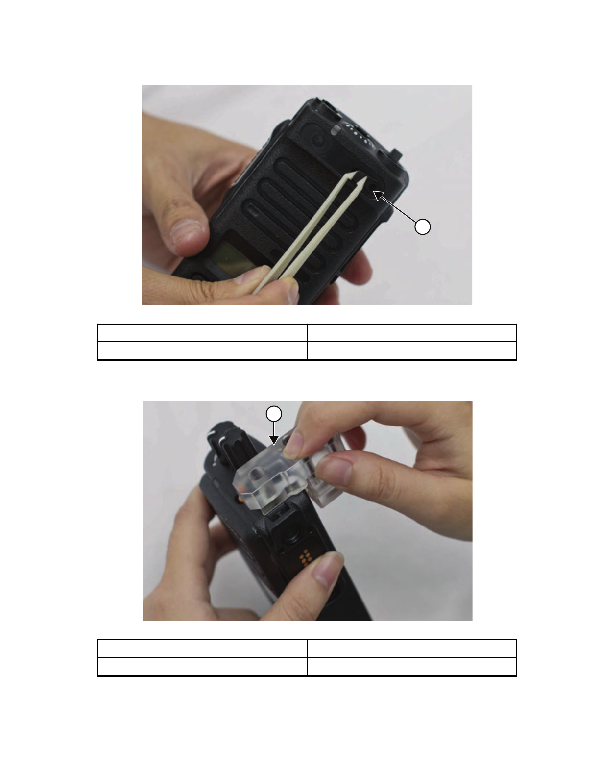
1
1
MN002211A01-AE
Chapter 4: Radio Programming and Tuning
Figure 9: RF Plug disassembly
Label Description
1 RF Plug
2 Insert the RF Adaptor into the front housing.
Figure 10: RF Adaptor insertion
Label Description
1 RF Adaptor
3 Screw in the RF adaptor to the front housing.
48
Page 49

Figure 11: RF Adaptor screw
MN002211A01-AE
Chapter 4: Radio Programming and Tuning
4 Insert the RF connector.
CAUTION: Do not attach the RF Connector into the RF Adapter Holder before inserting
the RF Adapter Holder into the housing.
Figure 12: RF Connector
49
Page 50
MN002211A01-AE
Chapter 5: Disassembly/Reassembly Procedures
Chapter 5
Disassembly/Reassembly Procedures
This chapter provides details about the following:
• Preventive maintenance (inspection and cleaning).
• Safe handling of CMOS and LDMOS devices.
Repair procedures and techniques.
•
• Disassembly and reassembly of the radio.
5.1
Preventive Maintenance
Periodic visual inspection and cleaning are recommended.
Inspection
Check that the external surfaces of your radio are clean, and that all external controls and switches are
functional. It is not recommended to inspect the interior electronic circuitry.
Cleaning Procedures
The following procedures describe the recommended cleaning agents and the methods to clean the
external and internal surfaces of your radio.
External surfaces include the front cover, housing assembly, and battery. These surfaces should be
cleaned whenever a periodic visual inspection reveals the presence of smudges, grease, and/or grime.
CAUTION: Use all chemicals as prescribed by the manufacturer. Follow all safety precautions
as defined on the label or material safety data sheet.
The effects of certain chemicals and their vapors can have harmful results on certain plastics.
Avoid using aerosol sprays, tuner cleaners, and other chemicals.
NOTICE:
Only clean internal surfaces when your radio is disassembled for service or repair.
Cleaning External Plastic Surfaces
IMPORTANT: The only recommended agent for cleaning the external radio surfaces is a 0.5%
solution of a mild dish-washing detergent in water.
Apply the 0.5% detergent-water solution sparingly with a stiff, non-metallic, short-bristled brush to work
all loose dirt away from your radio. Use a soft, absorbent, lint-less cloth, or tissue to remove the
solution and dry your radio. Make sure that no water remains entrapped near the connectors, cracks,
or crevices.
Cleaning Internal Circuit Boards and Components
IMPORTANT:
The only factory recommended liquid for cleaning the printed circuit boards and their
components is isopropyl alcohol (100% by volume).
Always use fresh supply of alcohol and a clean container to prevent contamination by
dissolved material (from previous usage).
50
Page 51

MN002211A01-AE
Chapter 5:
Apply Isopropyl alcohol (100%) with a stiff, non-metallic, short-bristled brush to dislodge embedded or
caked materials located in hard-to-reach areas. The brush stroke should direct the dislodged material
out and away from the inside of your radio. Make sure that controls or tunable components are not
soaked with alcohol. Do not use high-pressure air to hasten the drying process since it can cause the
liquid to collect in unwanted places. After completing of the cleaning process, use a soft, absorbent,
lint-less cloth to dry the area. Do not brush or apply any isopropyl alcohol to the frame, front cover, or
back cover.
5.2
Disassembly/Reassembly Procedures
Safe Handling of CMOS and LDMOS Devices
Complementary Metal Oxide Semiconductor (CMOS) and Laterally Diffused Metal Oxide
Semiconductor (LDMOS) devices are used in this family of radios, and are susceptible to damage by
electrostatic or high-voltage charges.
Damage can be latent, resulting in failures occurring weeks or months later. Therefore, special
precautions must be taken to prevent device damage during disassembly, troubleshooting, and repair.
Handling precautions are mandatory for CMOS/LDMOS circuits and are especially important in low
humidity conditions. Do not attempt to disassemble your radio without referring to the following caution
statement.
CAUTION:
This radio contains static-sensitive devices. Do not open your radio unless you are properly
grounded. Take the following precautions when working on this unit:
• Store and transport all CMOS/LDMOS devices in conductive material so that all exposed
leads are shorted together. Do not insert CMOS/LDMOS devices into conventional plastic
"snow" trays used for storage and transportation of other semiconductor devices.
Ground the working surface of the service bench to protect the CMOS/LDMOS device. It is
•
recommended that you use a wrist strap, two ground cords, a table mat, a floor mat,
electrostatic discharge (ESD) shoes, and an ESD chair.
• Wear a conductive wrist strap in series with a 100k resistor to ground. Replacement wrist
straps that connect to the bench top covering are Motorola Solutions part number
4280385A59.
• Do not wear nylon clothing while handling CMOS/LDMOS devices.
• Do not insert or remove CMOS/LDMOS devices with power applied. Check all power
supplies used for testing CMOS/LDMOS devices to be certain that there are no voltage
transients present.
• When straightening CMOS/LDMOS pins, provide ground straps for the apparatus used.
• When soldering, use a grounded soldering iron.
• Handle CMOS/LDMOS devices by the package and not by the leads. Before touching the
unit, touch an electrical ground to remove any static charge that you may have accumulated.
The package and substrate may be electrically common. If so, the reaction of a discharge to
the case would cause the same damage as touching the leads.
5.3
General Repair Procedures and Techniques
Environmentally Preferred Products (EPP) were developed and assembled using
environmentally preferred components and solder assembly techniques to comply with the European
Union's Restriction of Hazardous Substances (ROHS 2) Directive 2011/65/EU and Waste Electrical
and Electronic Equipment (WEEE) Directive 2012/19/EU. To maintain product compliance and
reliability, use only the Motorola Solutions specified parts in this manual.
51
Page 52
MN002211A01-AE
Chapter 5: Disassembly/Reassembly Procedures
For the identification of lead (Pb) free assemblies, all EPP products carry the EPP Marking, shown in
the following examples, on the Printed Circuit Board (PCB). This marking provides information to those
performing assembly, servicing, and recycling operation on this product, adhering to the JEDEC
Standard No. 97. The EPP Marking takes the form of a label or marking on the PCB.
Any rework or repair on Environmentally Preferred Products must be done using the appropriate leadfree solder wire and lead-free solder paste as stated in the following tables:
Table 32: Lead Free Solder Wire Part Number List
Motorola
Solutions
Part Number
1088929Y01 95.5Sn/3.8Ag/
Table 33: Lead Free Solder Paste Part Number List
Manufacturer
Part Number
NC-SMQ230 900–1000KCPs
Alloy Flux Type Flux Con-
tent by
Weight
RMA Ver-
0.7Cu
Viscosity Type Composition
Brookfield (5
rpm)
sion
Type 3
(-325/+500)
2.7–3.2% 217 °C 52171 0.015
and Percent
Metal
(95.5%Sn-3.8%A
g-0.7%Cu)
89.3%
Melting
Point
Supplier
Part number
Liquid Temperature
217 °C
Diameter
in.
Weight
1 lb
spool
Parts Replacement and Substitution
When damaged parts are replaced, identical parts must be used. If the identical replacement part is not
locally available, check the parts list for the proper Motorola Solutions part number and order the part.
Rigid Circuit Boards
This family of radios use bonded, multi-layer, printed circuit boards. Since the inner layers are not
accessible, some special considerations are required when soldering and unsoldering components.
The plated-through holes may interconnect multiple layers of the printed circuit. Therefore, exercise
care to avoid pulling the plated circuit out of the hole.
When soldering near a connector:
• Avoid accidentally getting solder in the connector.
•
Be careful not to form solder bridges between the connector pins.
• Examine your work closely for shorts due to solder bridges.
For soldering components with Hot-Air or infra red solder systems, check the user guide of your solder
system to get information on solder temperature and time for the different housings of the integrated
circuits and other components.
52
Page 53

MN002211A01-AE
Chapter 5: Disassembly/Reassembly Procedures
5.4
Disassembling and Reassembling the Radio
When disassembling and reassembling the radio, it is important to pay particular attention to the snaps
and tabs, and how parts align with each other.
CAUTION: To assure the safety and regulatory compliance of your radio, repair your radio only
at Motorola Solutions service facilities. Please contact your local dealer or Point of Sale for
further instructions.
The following tools are required for disassembling the radio:
• TORX™ T screwdriver
Chassis and Knob Opener (TL000013A01)
•
The following tools are required for reassembling the radio:
• Grease (1185937A01)
• TORX T screwdriver
• Vacuum Pump Kit (NLN9839) - Radio Immersibility Test
• Pressure Pump Kit (NTN4265) - Radio Immersibility Test
• Connector Fitting (5871134M01) - Radio Immersibility Test
• Fitting Seal (3271133M01) - Radio Immersibility Test
• Seal Port (3286058L01)
• Ventilation Label (LB000256A01)
NOTICE: If a unit requires further testing or service than is customarily performed at the basic
level, send radio to Motorola Solutions Service Center.
5.5
Detailed Radio Disassembly
The section describes the detailed disassembly procedure of your radio.
5.5.1
Front Kit from Chassis Disassembly
Procedure:
1 Turn off the radio.
2 Remove the battery:
a Release the battery latch by moving it into the unlock position.
53
Page 54

1
MN002211A01-AE
Chapter 5: Disassembly/Reassembly Procedures
Figure 13: Battery removal
Label Description
1 Latch
b With the latch released, slide the battery downwards.
Figure 14: Battery removal
3 Remove the battery from the radio.
4 Remove the antenna by turning it counterclockwise.
54
Page 55
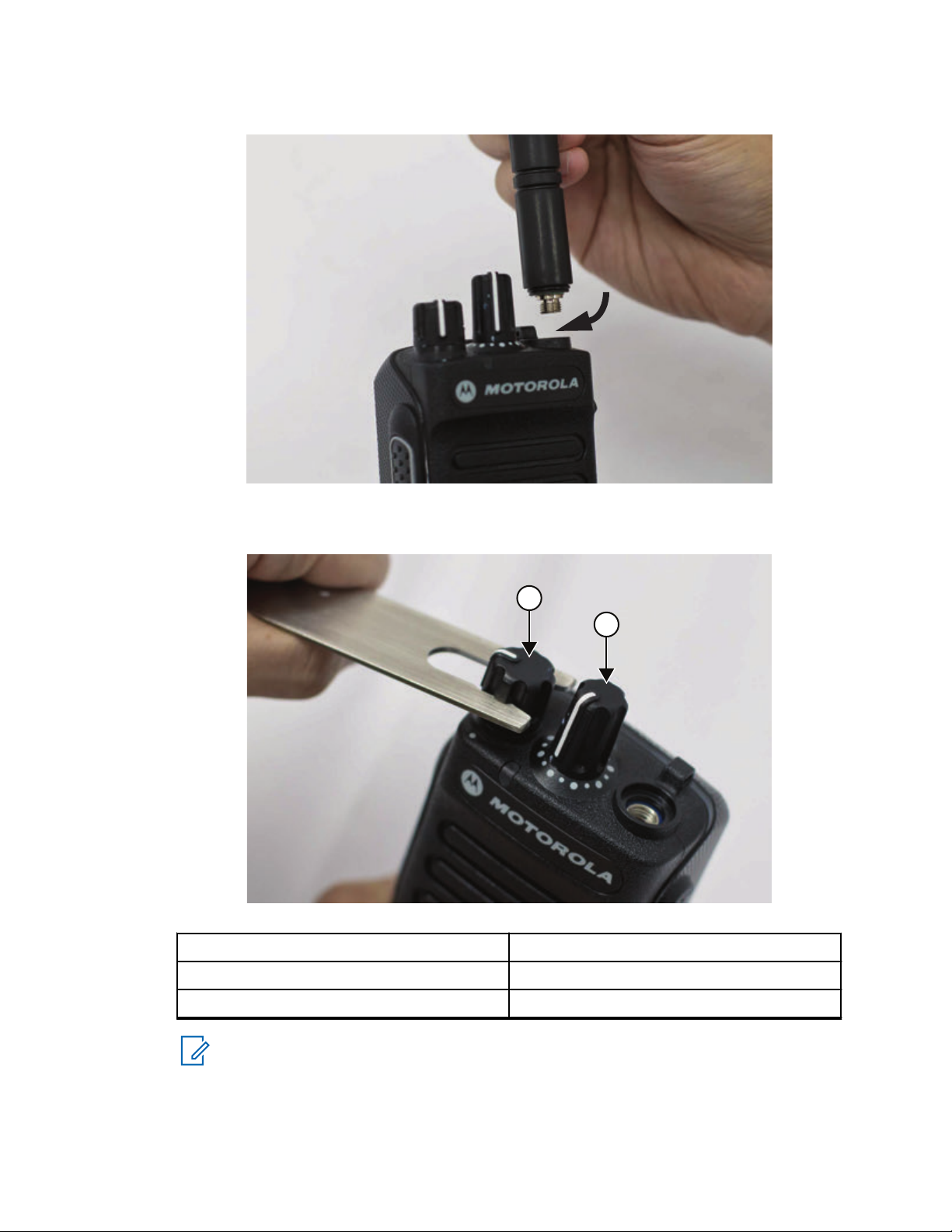
Figure 15: Antenna removal
1
2
Chapter
MN002211A01-AE
5: Disassembly/Reassembly Procedures
5 Remove the volume and channel knobs off from their shafts using the knob removal tool.
Figure 16: Volume and Channel Knob removal.
Label Description
1 Volume Knob
2 Channel Knob
NOTICE: Both knobs slide on and off. However, they are supposed to fit very tightly on
their shafts.
6 Separate the back kit from the front kit as follows:
a Unscrew the screw using TORX T6 screwdriver.
55
Page 56

MN002211A01-AE
Chapter 5: Disassembly/Reassembly Procedures
Figure 17: Front Kit-Back Kit Screw removal
b Use the chassis and knob opener to separate the back kit from the front kit.
Figure 18: Back Kit disassembly
c Slowly slide out the back kit from the front kit.
56
Page 57

Figure 19: Back Kit removal
1
2
MN002211A01-AE
Chapter 5: Disassembly/Reassembly Procedures
CAUTION:
Do not force the chassis out if it gets stuck by pulling it. This will cause damage to the
front kit.
Do not pull out the chassis forcefully as this will cause damage to the flex connector.
7 Lay the front kit down. Rotate the back kit backward and slightly away from the front kit.
8 Lift the Zero Insertion Force (ZIF) connector latch on the mainboard assembly to release the flex
and separate the back kit from the front kit.
Figure 20: Disconnecting the interface UC-audio flex and keypad-display flex (Limited
Keypad Model)
Label Description
1 Interface Keypad-Display Flex
57
Page 58
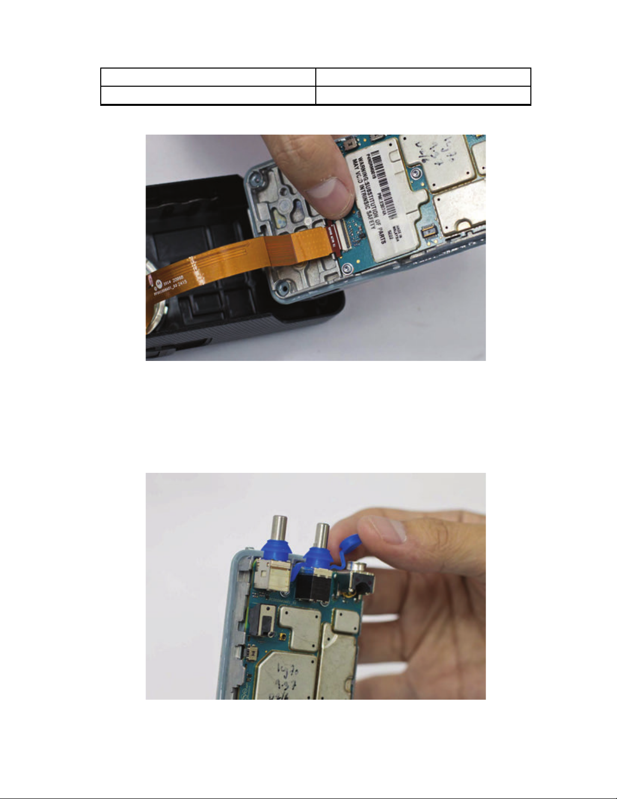
MN002211A01-AE
Chapter 5: Disassembly/Reassembly Procedures
Label Description
2 Interface UC-Audio Flex
Figure 21: Disconnecting the UC-audio flex (Non-Keypad Model)
5.5.2
Back Kit Disassembly
Procedure:
1 Remove the top control seal.
Figure 22: Top control seal removal
2 Use a TORX screwdriver with a T6 head to remove the five M2 screws holding the mainboard
assembly to the back kit.
58
Page 59
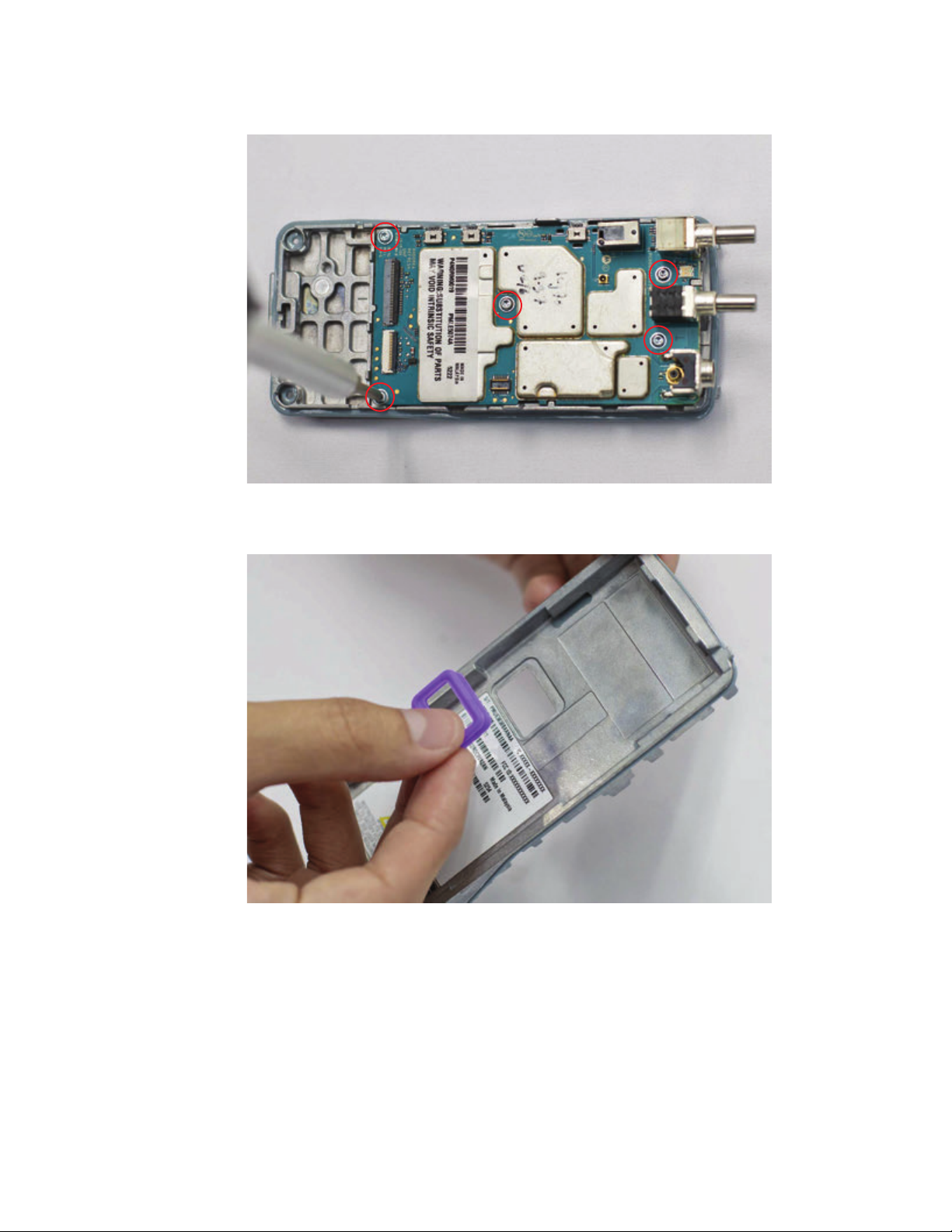
Figure 23: Back Kit disassembly
MN002211A01-AE
Chapter 5: Disassembly/Reassembly Procedures
3 Remove the battery contact seal.
Figure 24: Battery contact seal removal
5.5.3
Keypad, Display, and Keypad Board Disassembly
Procedure:
1 Disconnect the UC-audio flex.
59
Page 60

MN002211A01-AE
Chapter 5: Disassembly/Reassembly Procedures
Figure 25: UC-audio flex removal
2 Remove the display retainer after removing the two K18 screws.
Figure 26: K18 screw removal
3 Disconnect the display flex from the keypad board and remove it from the front kit.
60
Page 61

Figure 27: Display flex removal
1
2
MN002211A01-AE
Chapter 5: Disassembly/Reassembly Procedures
4 Remove the keypad and display module from the front kit.
Figure 28: Keypad removal
Label Description
1 Keypad
2 Display Module
61
Page 62
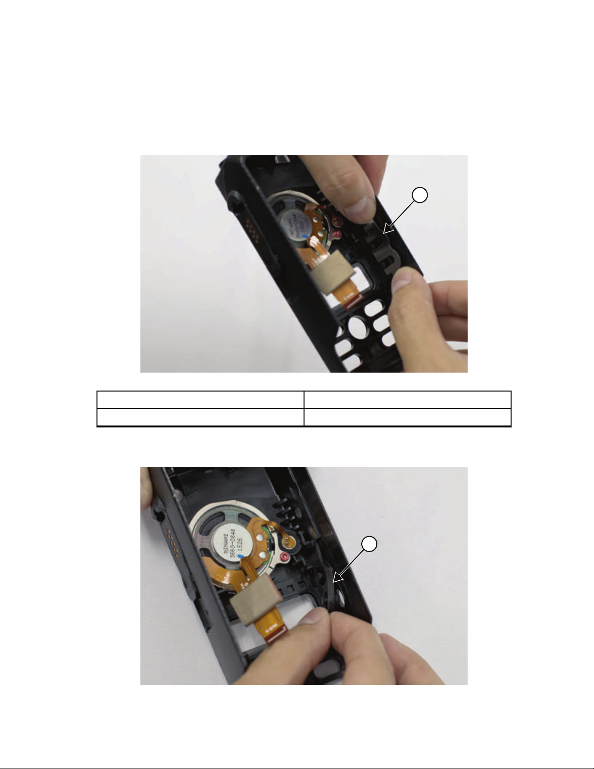
1
1
MN002211A01-AE
Chapter 5: Disassembly/Reassembly Procedures
5.5.4
Side Button, Speaker, Microphone, and UC-Audio Flex Disassembly
Procedure:
1 Pull out the PTT retainer.
Figure 29: PTT retainer removal
Label Description
1 PTT Retainer
2 Remove the side button.
Figure 30: Side button removal
62
Page 63

Chapter 5: Disassembly/Reassembly Procedures
Label Description
1 Side Button
3 Peel off the UC escutcheon.
Figure 31: UC escutcheon removal
MN002211A01-AE
4 Pull the UC-audio flex (adhesive held) FR4 from the front housing. Push the UC-audio flex
through the UC slot into the housing.
Figure 32: UC-audio flex removal
5 Remove the K18 screw securing the speaker retainer.
63
Page 64
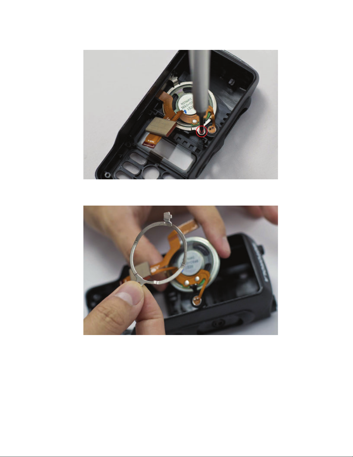
MN002211A01-AE
Chapter 5: Disassembly/Reassembly Procedures
Figure 33: Speaker retainer screw removal
6 Remove the speaker assembly from the front kit and separate the speaker module and retainer.
Figure 34: Speaker retainer removal
64
Page 65

MN002211A01-AE
Chapter 5: Disassembly/Reassembly Procedures
5.6
Detailed Radio Reassembly
The section describes the detailed reassembly procedure of your radio.
5.6.1
Speaker Reassembly
Procedure:
1 Insert the UC-audio flex through the speaker retainer so that the speaker retainer is placed
directly on the speaker assembly.
Figure 35: Speaker assembly
NOTICE: Ensure the flex is on top of the retainer to prevent it from being torn during
reassembly.
2 Use tweezers to pull UC-audio flex circuit through the UC slot and place the speaker assembly
in the recess on the front kit.
65
Page 66
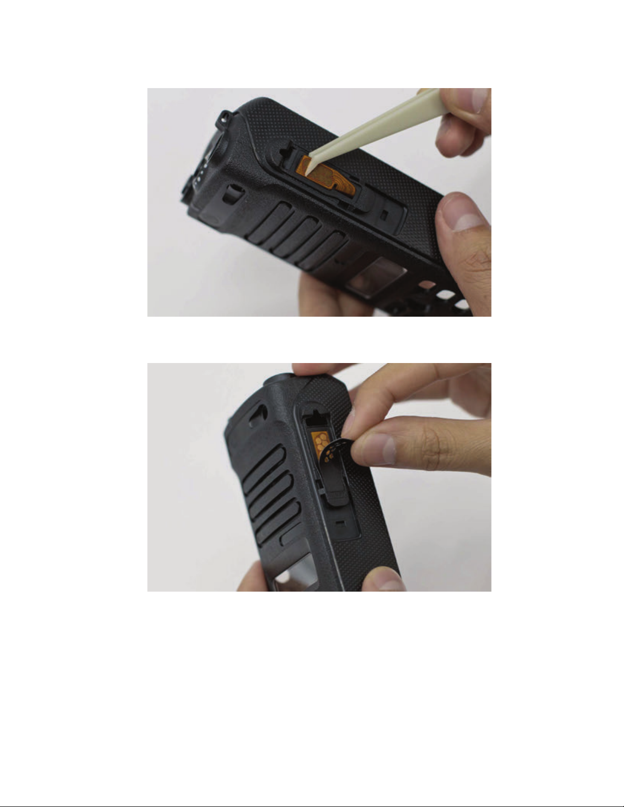
MN002211A01-AE
Chapter 5:
Disassembly/Reassembly Procedures
Figure 36: UC-audio flex
3 Replace with a new UC escutcheon.
Figure 37: UC escutcheon
4 Ensure the mic is seated properly in the mic boot. Screw in the K18 screw to the speaker
retainer.
66
Page 67
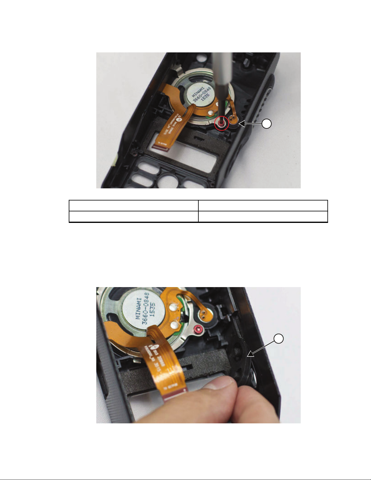
Figure 38: Speaker retainer reassembly
1
1
MN002211A01-AE
Chapter 5: Disassembly/Reassembly Procedures
Label Description
1 Mic
5.6.2
Side Button, Keypad, Display, and Keypad Board Reassembly
Procedure:
1 Insert side button to the front housing.
Figure 39: Side button reassembly
67
Page 68

1
MN002211A01-AE
Chapter 5: Disassembly/Reassembly Procedures
Label Description
1 Side Button
NOTICE: Ensure the side button is seated firmly without any pinching as this impacts the
sealing performance.
2 Replace the PTT retainer.
Figure 40: PTT retainer reassembly
Label Description
1 PTT Retainer
3 Place the display module into the display module recess.
Figure 41: Display module reassembly
68
Page 69

Chapter 5: Disassembly/Reassembly Procedures
4 Place the keypad into the front kit and press firmly in place.
Figure 42: Keypad reassembly
MN002211A01-AE
NOTICE: Ensure the keypad mushroom rib is fully seated in the sealing groove to
prevent any pinching or bulging.
5 Tongue in the keypad board.
Figure 43: Keypad board reassembly
6 Connect the display flex and gently latch it down.
69
Page 70
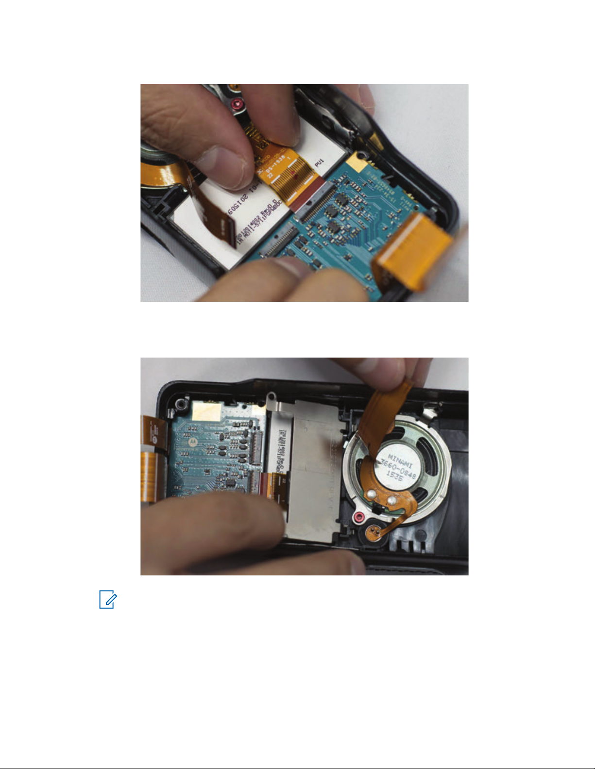
MN002211A01-AE
Chapter
5: Disassembly/Reassembly Procedures
Figure 44: Display flex reassembly
7 Hold up the UC-audio flex and insert the display retainer. Screw in the K18 screw to the speaker
retainer.
Figure 45: Speaker retainer reassembly
NOTICE: Ensure the UC-audio flex is not trapped under the speaker retainer.
8 Connect the UC-audio flex to the keypad board and gently press the Zero Insertion Force (ZIF)
connector until it latches shut.
9 Affix a poron pad on top of the UC-audio flex.
70
Page 71

Figure 46: UC-audio flex pad reassembly
MN002211A01-AE
Chapter 5: Disassembly/Reassembly Procedures
5.6.3
Back Kit Reassembly
Procedure:
1 Replace the thermal pad on the chassis.
Figure 47: Replace thermal pad
2 Affix the chassis label on both the left and right side of the chassis.
71
Page 72
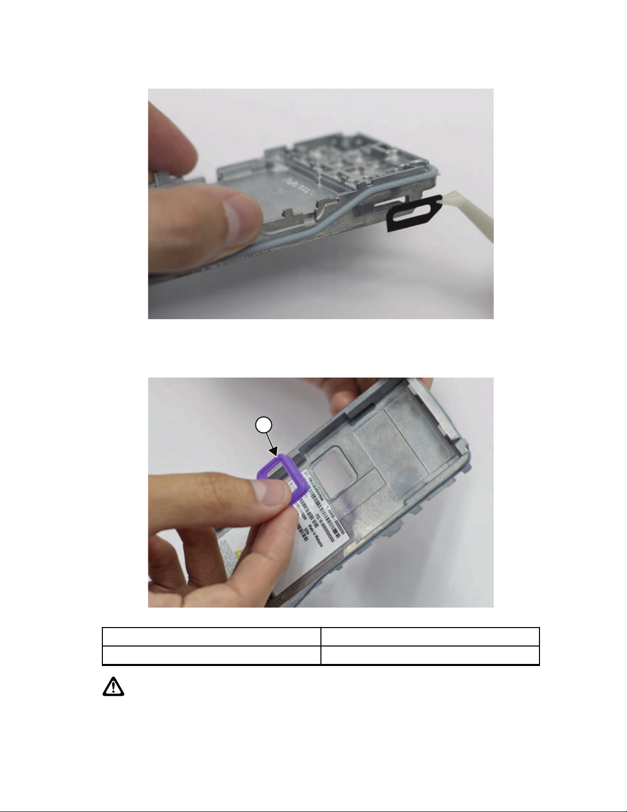
1
MN002211A01-AE
Chapter 5: Disassembly/Reassembly Procedures
Figure 48: Affix chassis label
3 Replace battery contact seal on the chassis. Orientate the battery contact seal so that the wider
edge is at the top side.
Figure 49: Battery contact seal reassembly
Label Description
1 Wider Edge
CAUTION: Make sure the battery contact seal is not twisted or lifted when the mainboard
assembly is placed on the chassis.
4 Place the mainboard assembly on the chassis and replace the five M2 screws.
72
Page 73

Figure 50: Mainboard reassembly
1
5 4
2
3
1
MN002211A01-AE
Chapter 5: Disassembly/Reassembly Procedures
Label Description
1-5 Five M2 screws
5 Insert the top control seal into the volume and channel shaft. Push on the wing of the top control
seal as shown in Figure 51: Top control seal reassembly on page 73, until it is seated on the
base of the switches.
Figure 51: Top control seal reassembly
Label Description
1 Wing
73
Page 74
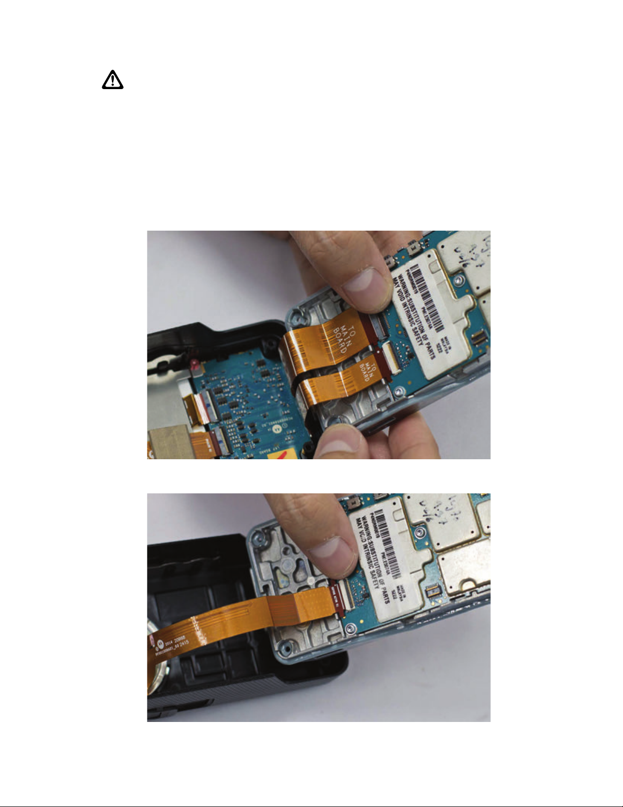
MN002211A01-AE
Chapter 5: Disassembly/Reassembly Procedures
CAUTION: Ensure the top control seal is seated properly on the shafts.
5.6.4
Front Kit Reassembly
Procedure:
1 Apply a thin layer of grease to the full perimeter of the dispensed O-ring.
2 Connect the two flexes to the mainboard Zero Insertion Force (ZIF) connector and gently latch it
firmly shut.
Figure 52: Interface flexes reassembly (Limited Keypad Model)
Figure 53: Interface flexes reassembly (Non-Keypad Model)
3 Slide the back kit into the front kit and firmly press down to snap it in.
74
Page 75
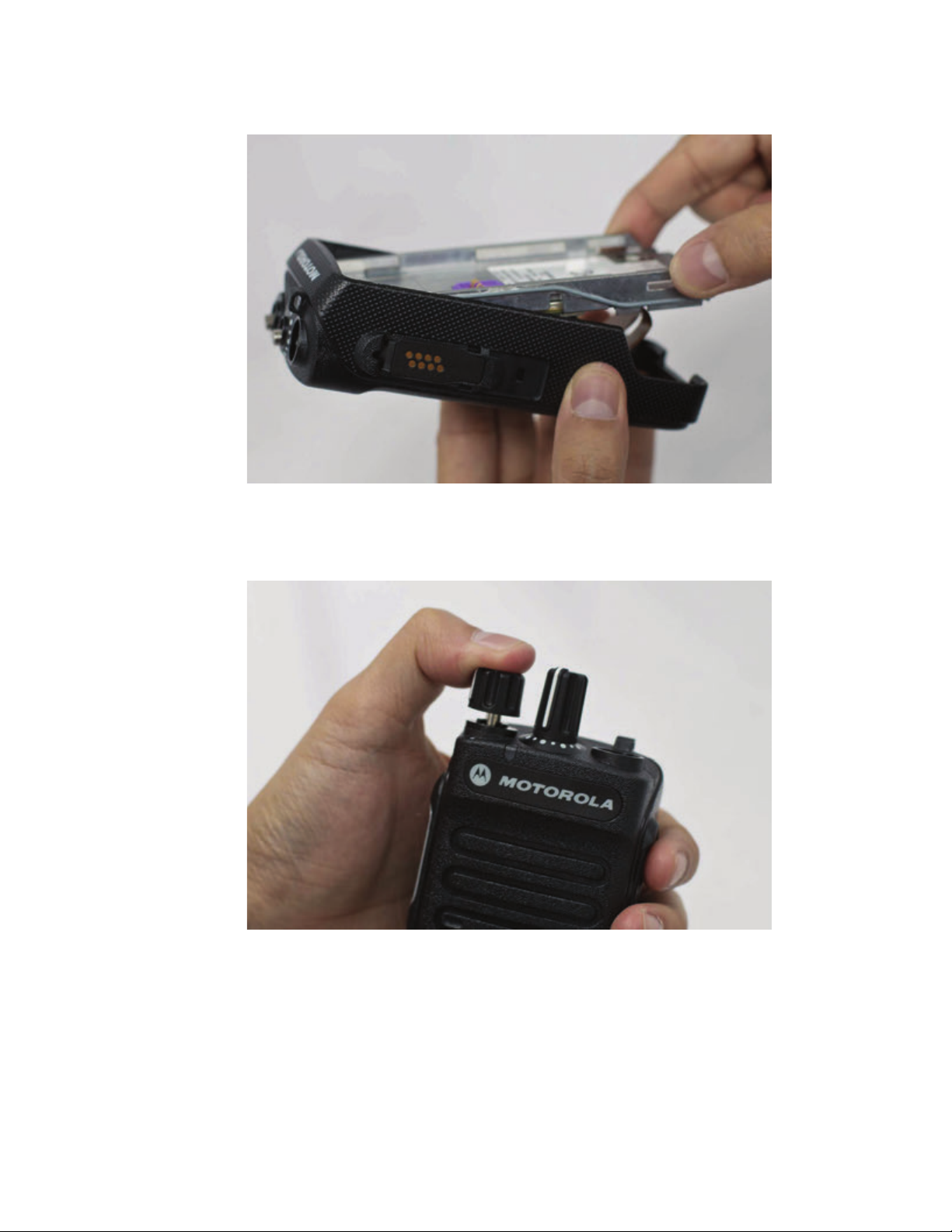
Figure 54: Front kit reassembly
MN002211A01-AE
Chapter 5: Disassembly/Reassembly Procedures
4 Fasten the two Front Kit-Back Kit screws by using TORX T6 screwdriver.
5 Slide in the volume and channel knob fully on the shafts on the front kit.
Figure 55: Knob reassembly
6 Attach antenna by turning it in clockwise.
75
Page 76

MN002211A01-AE
Chapter 5: Disassembly/Reassembly Procedures
Figure 56: Attaching the antenna
5.6.5
RF Plug Reassembly
Procedure:
1 Replace the RF plug by using tweezers.
Figure 57: RF Plug reassembly
2 If Motorola Solutions nameplate is damaged, remove nameplate with tweezers and replace a
new one.
76
Page 77
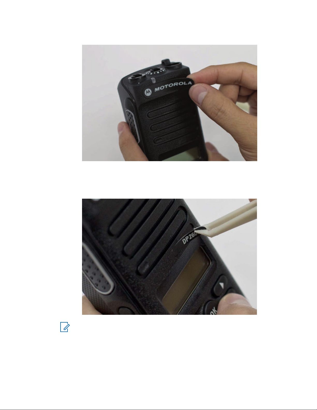
Figure 58: Nameplate replacement
MN002211A01-AE
Chapter 5: Disassembly/Reassembly Procedures
3 Make sure the RF plug and nameplate are flushed to the housing and not bulging up. If it bulges
up, disassemble and reassemble back.
4 If product nameplate is damaged, remove nameplate with tweezers and replace a new one.
Figure 59: Product nameplate reassembly
NOTICE: Maintain this area regularly, at least annually, to prolong battery contacts life
and free interface from contamination.
77
Page 78

MN002211A01-AE
Chapter 5: Disassembly/Reassembly Procedures
5.7
Ensuring Radio Immersibility
This section discusses radio immersibility concerns, tests, and disassembly and reassembly of the
radios.
5.7.1
Servicing
Radios shipped from the Motorola Solutions factory have passed vacuum testing and are capable of
restoring the watertight integrity of your radio.
CAUTION: It is strongly recommended to defer your radio maintenance to qualified service
personnel and service shops. This is of paramount importance as service by unauthorized
persons may cause irreparable damage to your radio. If disassembly is necessary,
unauthorized attempts to repair the radio may void any existing warranties or extended
performance agreements with Motorola Solutions. It is also recommended for qualified service
personnel/workshop that is authorized by Motorola Solutions to perform annual check on your
radio immersibility.
5.7.2
Accidental Immersion
If radio is accidentally dropped into water, shake your radio to remove the excess water from the
speaker grille and microphone port area before operating. Otherwise, the sound may be distorted until
water has evaporated, or is dislodged from these areas.
5.7.3
Specialized Test Equipment
This section summarizes the specialized test equipment necessary for testing the integrity of the
radios.
To ensure that the radio is truly a watertight unit, special testing, test procedures, and specialized test
equipment are required. The special testing involves a vacuum check of the radio and pressure testing
(troubleshooting) for water leaks. if the vacuum check fails. The specialized test equipment/instrument
mentioned in the Service Aids is authorized by Motorola Solutions and is used to perform the vacuum
check and pressure testing, if required. Any equipment/tools/instruments not mentioned in this chapter
must not be used to perform these tests.
5.7.4
Vacuum Pump Kit
The vacuum pump kit includes a vacuum pump with gauge, and a vacuum hose.
A connector fitting (5871134M01) and fitting seal (3271133M01) pump connector, which must be
ordered separately, connects the vacuum hose to the radio chassis.
78
Page 79
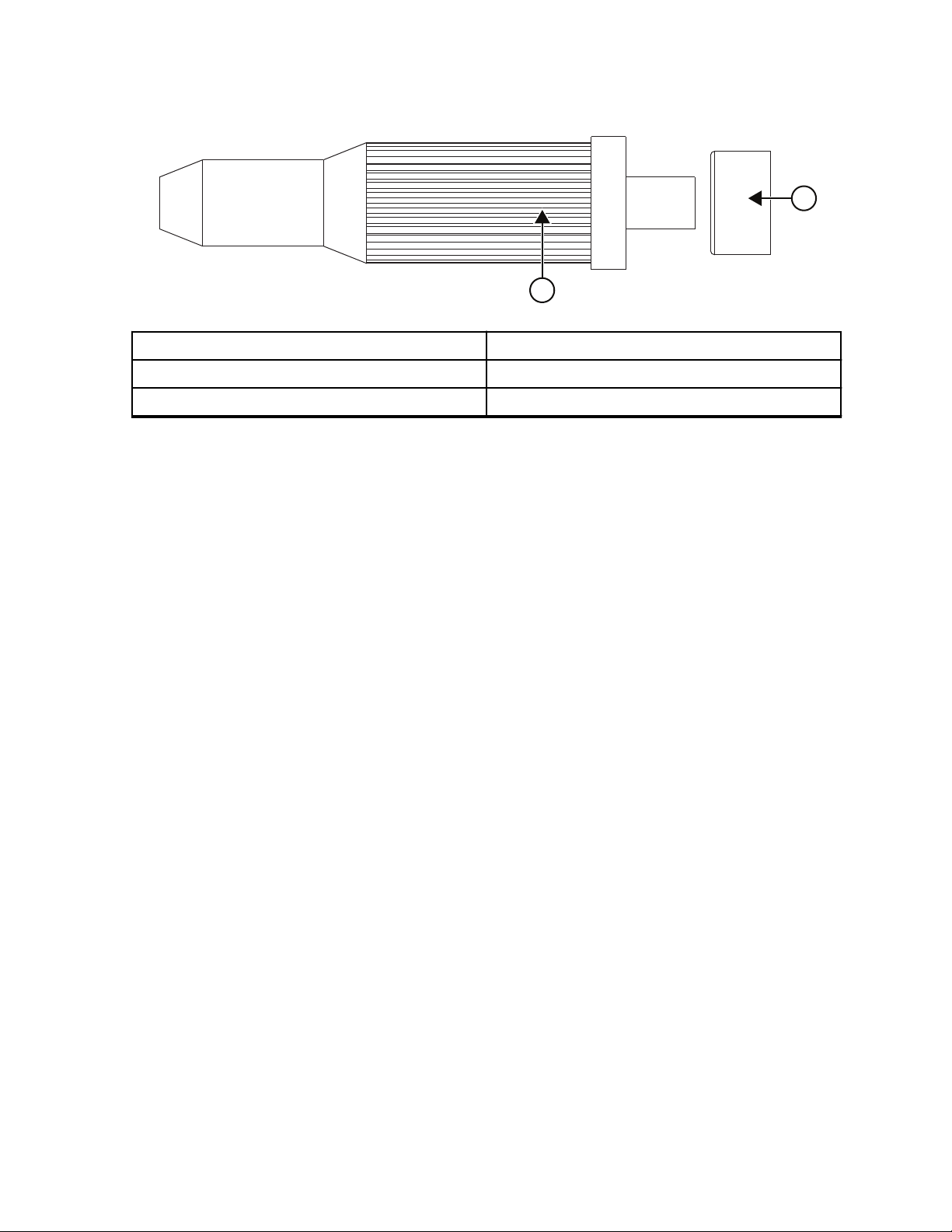
2
1
Chapter 5: Disassembly/Reassembly Procedures
Figure 60: Connector Fitting - Fitting Seal Pump Connector
Label Description
1 Fitting Seal
2 Connector Fitting
5.7.5
Pressure Pump Kit
MN002211A01-AE
The pressure pump kit includes a pressure pump with gauge, and a pressure hose.
With the vacuum pump kit, the connector fitting - fitting seal pair connects the pressure hose to the
radio chassis.
5.7.6
Miscellaneous Hardware
Other items needed for testing radio immersibility are:
• Large water container
• Deionized (DI) water
• A supply of replacement parts: Battery Contact Seal, Breathing Vent Label, and Breathing Vent
Membrane.
5.7.7
Vacuum Test
The vacuum test uses a vacuum pump and gauge. The pump creates a vacuum condition inside the
radio, and the gauge monitors the radio for a stable vacuum reading; that is, checking for a properly
sealed, watertight unit.
Prerequisites:
• Remove the battery.
• Remove the universal connector dustcover to expose the universal connector.
• Remove the breathing vent label and breathing vent membrane.
Procedure:
1 Attach antenna firmly to the radio.
2 Attach the vacuum hose to the vacuum pump. Check the pump and hose for leaks by blocking
off the open end of the hose and operating the pump a few times.
The actual reading of the gauge at this point is not important; it is important that the gauge
pointer remained steady, indicating no vacuum leaks in the pump.
79
Page 80

MN002211A01-AE
Chapter 5: Disassembly/Reassembly Procedures
3 Ensure that the fitting seal is attached to the hose-to-chassis pump connector. Screw the pump
connector into the tapped hole in the chassis.
CAUTION: Do not bend or over tighten pump connector to the chassis.
4 Attach the open end of the hose to the pointed end of the pump connector.
5 Place the radio on a flat surface with the chassis facing upward.
6 Operate the pump until the gauge indicates 6 in. Hg of vacuum on the radio. Observe the gauge
for approximately
• If the needle falls 0.5 in. Hg or less (one scale interval, for example, from 3 in. Hg to 2.5 in.
Hg), then the radio has passed the vacuum test and is approved for immersibility. No
additional testing will be required.
• If the needle falls more than 0.5 in. Hg (one scale interval, for example, from 3 in. Hg to less
than 2.5 in. Hg), then the radio has failed the vacuum test and the radio might leak if
immersed. Additional troubleshooting of the radio will be required; complete this procedure,
then go to Pressure Test on page 80.
7 Remove the vacuum hose and pump connector from the radio.
5.7.8
1 min.
Pressure Test
Pressure testing involves creating a positive pressure condition inside your radio, immersing radio in
water, and observing radio for a stream of bubbles (leak). Since all areas of your radio are being
checked, observe the entire unit carefully for the possibility of multiple leaks before completing this test.
NOTICE: Pressure testing the radio is necessary only if the radio has failed the vacuum test. Do
not perform the pressure test until the vacuum test has been completed.
Procedure:
1 Screw the pump connector (with fitting seal) into the tapped hole in the chassis.
2 Attach one end of the pressure hose to the pump connector and the other end to the pressure
pump.
3 Attach antenna firmly to your radio.
4 Operate the pump until the gauge reads approximately 1 psig.
CAUTION: Pressure any greater than 1 psig might push air around the main seal.
5 Maintain the pressure at 1 psig and immerse the radio into a water-filled container.
6 Watch for any continuous series of bubbles.
A stream of bubbles indicates a sign of leakage. Some air entrapment may cause the
accumulation of bubbles, especially in the grille area, but the bubbles should not be continuous.
CAUTION: Do not bend or over tighten pump connector to the chassis.
7 Note all of the seal areas that show signs of leakage.
Pinpoint the problem to the following areas:
• Front Housing
•
Chassis kit
• Battery Contact Seal
8 Remove the radio from the water container, and dry the radio thoroughly.
80
Page 81

MN002211A01-AE
Chapter
CAUTION: Keep the area around the chassis vacuum port dry by ensuring that there is
no water around it.
NOTICE: Dry the area around the main seal with extra care to prevent contamination of
the internal electronics while the unit is open.
9 Remove the pump connector from the chassis.
Postrequisites: After performing Pressure Test, your radio must undergo baking process in a
temperature chamber for constant temperature soaking at 60 °C for 1 hour. This is to ensure no
moisture is trapped inside the radio and prevent contamination of the internal electronics after
reassembling the radio.
5.7.9
Disassembly/Reassembly Procedures
5:
Troubleshooting Leak Areas
Before repairing any leak, read steps in the applicable section. This helps to eliminate unnecessary
disassembly and reassembly of a radio with multiple leaks.
Troubleshoot only the faulty seal areas listed in Pressure Test
exist, in the order listed.
NOTICE:
Before reassembling the radio, always install a Battery Contact Seal in the defective area.
on page 80, and when multiple leaks
5.7.9.1
Front Housing Troubleshooting
Procedure:
Do one or both of the following:
• If a leak occurs at the Lens (Display Models only), Universal Connector, Chassis/Housing
interface, or PTT button area of the housing, replace the housing, refer to Detailed Radio
Disassembly
1 Remove the housing assembly from the radio.
2 Discard the housing assembly.
3 Install a new housing assembly to the radio.
• If the leak occurs at the control top area, remove the knobs in order to determine the leak
location:
1 Conduct the Pressure Test.
2 Identify the leak location.
5.7.9.2
on page 53.
Replacing Battery Contact Seal
Procedure:
1 Remove the Battery Contact Seal from the Chassis. Refer to "Radio Disassembly" Chapter.
2 Inspect the Battery Contact Seal, Chassis, and surrounding areas for foreign material that might
prevent the Battery Contact Seal from sealing properly.
3 Install a new Battery Contact Seal, discard the old Seal.
4 Reassemble the Chassis assembly followed by installing into Front Kit. Refer to "Radio
Reassembly" Chapter.
81
Page 82

MN002211A01-AE
Chapter 5: Disassembly/Reassembly Procedures
5.7.9.3
Replacing Chassis Assembly
Procedure:
1 Remove the chassis assembly from the radio. Refer to Front Kit from Chassis Disassembly on
page 53
2 Remove the Mainboard from chassis. Refer to Back Kit Disassembly on page 58.
3 Assemble a new chassis assembly; discard the old chassis assembly.
4 Reassemble the chassis assembly followed by installing into front kit. Refer to Detailed Radio
Reassembly on page 65.
5.7.9.4
.
Replacing Ventilation Seal and Ventilation Label
Prerequisites: Both Ventilation Label and Gasket need to be replaced after vacuum test, pressure
test, or water leakage troubleshooting.
Procedure:
1 Remove the Ventilation Label that covers the Ventilation Seal from the chassis.
2 Remove the Ventilation Seal.
3 Ensure that the chassis surface (at the Ventilation Label and Ventilation Seal recess) is clean,
no/minimum scratches and free from any adhesive or other foreign materials.
4 Install a new Ventilation Seal, covering the vent port hole, in the small recessed area in the
chassis. Ensure that no oily substance is in contact with the seal.
5 Install a new Ventilation Label over the Ventilation Seal in the larger recessed area in the
chassis. Press down evenly over the label surface to ensure good adhesion.
5.7.9.5
Battery Maintenance
Maintain your radio battery annually or as required; when battery contacts are dirty or show signs of
wear. Battery Maintenance prolongs battery contacts life and free battery interface from contamination.
It is recommended that the Battery Radio-side and Charger-side contacts are cleaned with DeoxIT
GOLD cleaner/lubricant.
DeoxIT GOLD (Supplier CAIG Labs, part number: G100P) cleaner/lubricant pen is very effective at
cleaning and extending the life of the battery contacts. DeoxIT GOLD cleaner/lubricant pen is available
at numerous electronics suppliers (Radio Shack, McMaster Carr, Fry's, and more) and directly from
manufacturer, CAIG Labs, at http://www.caig.com.
This pen-based package is recommended as it provides better access to the recessed contacts of the
battery. The pen tip may need to be modified (trimmed on the sides) to improve penetration into the
battery contact slots.
Advanced contact wear is defined as wear through the contact platings (gold and nickel) to the base
metal (copper). Copper exposure is characterized by a distinctive
orange-brown metal appearance surrounded by silvery nickel underplate and gold top coat.
In some cases, a magnified (10 times minimum) inspection may be required to verify wear through to
the base material. Polishing of the gold or nickel surface is common and is not considered as a need
for replacement. Replace battery when advanced wear is evident.
82
Page 83

MN002211A01-AE
Chapter 5: Disassembly/Reassembly Procedures
5.7.9.5.1
Maintaining the Battery
Procedure:
1 Shake the lubricant pen until the fluid begins to flow.
2 Wipe battery contact surface with felt tip.
3 After cleaning the contact areas of any foreign material, let the lubricant/cleaner dry for 2
minutes.
4 Replace the battery on the radio. Make sure the battery is attached properly on the radio.
Postrequisites: After cleaning, inspect the contact surfaces for signs of advanced contact wear. See
Battery Maintenance on page 82 for advanced contact wear.
83
Page 84

Start
1. Remove Battery
2. Remove Universal
Connector Dustcover
3. Remove ventilation label
and seal
1. Attach antenna firmly to the radio.
2. Attach vacuum hose to vacuum
pump
3. Ensure fitting seal is attached to
hose-to-chassis pump connector
4. Screw pump connector into
chassis’s tapped hole
5. Attach vacuum hose to pump
connector
6. Place radio on flat surface
7. Operate pump (gauge = 6 in. Hg)
Gauge
does not fall
below
0.5 in. Hg
No
Yes
Run Pressure Test
1.Replace
ventilation label
and seal
2. Radio approved
for immersibility
Full
equipment for
pressure test
procedure
available
Yes
No
B
End
A
MN002211A01-AE
Chapter 5: Disassembly/Reassembly Procedures
5.7.10
Troubleshooting Charts
Figure 61: Troubleshooting Flow Chart for Vacuum Test (Sheet 1 of 2)
84
Page 85

Start
B
1.Remove pump and
connectors from radio
2. Remove antenna
3. Separate front housing kit
Replace front
housing kit with
new unit
Apply grease to the full
perimeter of the chassis O-ring
and replace the Chassis Kit
without PCBs
Yes
No
No
Changed
front housing
kit
Changed
chassis
kit
Yes
Send radio to
Motorola Depot
or
Motorola Service Center
End
A
Chapter 5: Disassembly/Reassembly Procedures
Figure 62: Troubleshooting Flow Chart for Vacuum Test (Sheet 2 of 2)
MN002211A01-AE
85
Page 86
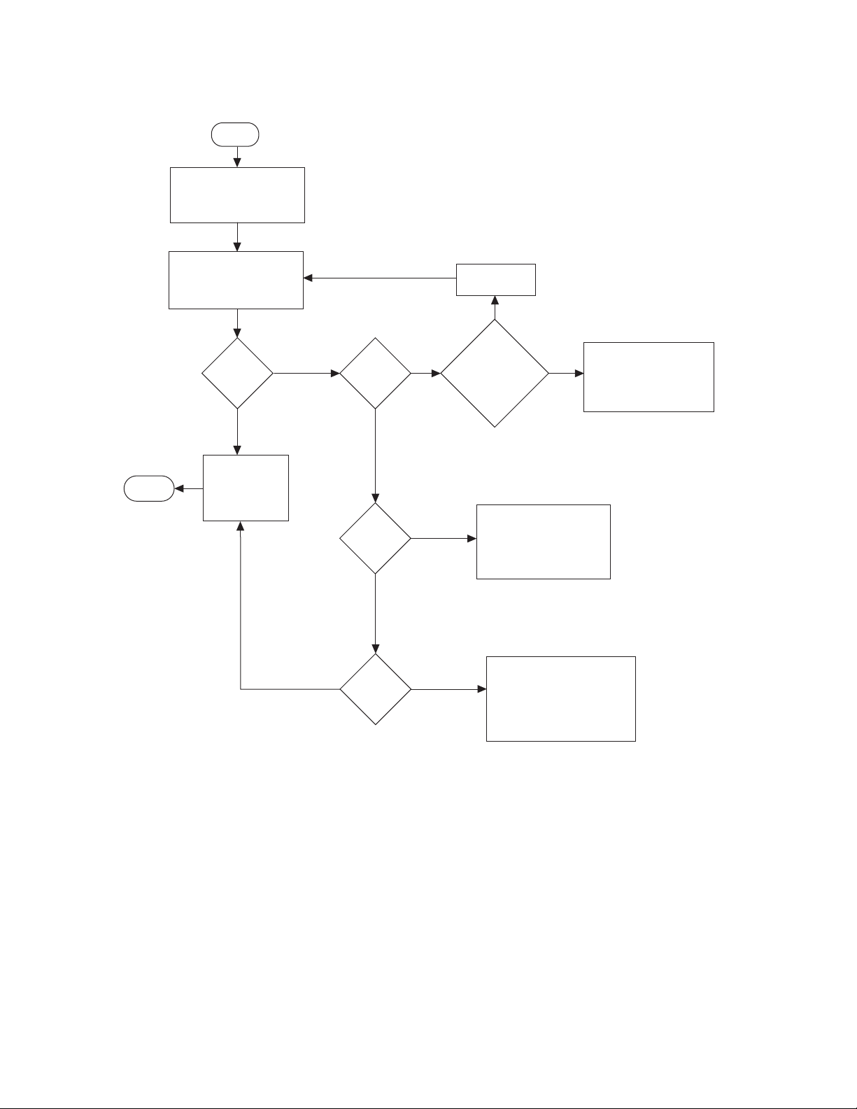
Start
1. Remove vacuum hose from
pump connector
2. Attach pressure hose to
pump connector
1. Operate pressure pump
(pressure = 1 psig)
2. Immerse radio into a waterfilled container
Continuous
Series of
bubbles
Yes
No
Bubbles from
Front
Housing
Yes
No
Bubbles from
Chassis
Yes
No
Bubbles from
Battery Con-
tact Seal
Yes
No
Bubbles from
Lens*/Universal Connector/
chassis/
Housing Inter-
face/ PTT
1. Dry the radio
2. Apply grease to the full
perimeter of the chassis O-Ring
and replace Chassis Kit and
repeat steps in Troubleshooting
Flow Chart for Vacuum Test
Yes
1. Remove Knobs
No
1. Dry the radio
2. Replace Battery Contact Seal,
Apply grease to the full
perimeter of the chassis O-Ring
and replace Chassis Kit. Repeat
steps in Troubleshooting Flow Chart
for Vacuum Test
1. Dry the radio
2. Apply grease to the full
perimeter of the chassis O-Ring
and replace Chassis Kit and
repeat steps in Troubleshooting
Flow Chart for Vacuum Test
1. Dry the radio
2.Replace
Ventilation Label and
Ventilation Seal
3. Radio approved
for immersibility
* Only for Display Model
End
MN002211A01-AE
Chapter 5: Disassembly/Reassembly Procedures
Figure 63: Troubleshooting Flow Chart for Pressure Test and Leakage Areas
86
Page 87

17
16
18
15
10.2.5.1
10.2.5
10.2.4
10.2.3
10.1
10.2.2
9.14
9.23
9.22
9.21
9.20
9.19
9.18
9.17
9.16
9.15
9.14
9.13
9.12
9.11
9.10
9.9
9.8
9.7
8
9.6
7
6
5
4
3
2
1
9.5
9.4
9.3
9.2
9.1
10.2.1
10.2.5.2
11
12
13
14
Chapter 5: Disassembly/Reassembly Procedures
5.8
Radio Exploded Mechanical View and Parts List
5.8.1
Limited Keypad Model
Figure 64: Limited Keypad Model Exploded View
MN002211A01-AE
87
Page 88

MN002211A01-AE
Chapter 5: Disassembly/Reassembly Procedures
Table 34: Limited Keypad Model Exploded View Parts List
Label Description Part Number
1 Nameplate (Product Number) Refer to Additional Parts
List on page 92
2 Nameplate (Motorola Solutions)
33012026001
3 RF Plug 38012018001
4 Volume Knob 36012016001
5 Channel Knob 36012017001
6 Antenna ID Band Refer to Additional Parts
List on page 92
7 Antenna Refer to Additional Parts
List on page 92
8 Aesthetic Cover 0104058J40
9 Front Kit PMLN7271_
9.1 PTT Retainer 42012035001
9.2 Side Button KP000087A01
9.3 Housing Assembly 0104067J09
9.4 PTT Keypad KP000086A01
9.5 PTT Paddle HN000696A01
9.6 UC Escutcheon 33012020001
9.7 Microphone Membrane SL000209A01
9.8 Microphone Boot SL000208A01
9.9 Microphone 50012012001
9.10 Speaker Mesh HW000738A01
9.11 Speaker AC000028A02
9.12 UC-Audio Flex PF001002A01
9.13 Speaker Retainer 42012044001
9.14 K18 Screw (Keypad-Display
0385273D06
Retainer and Speaker Retainer)
9.15 Front Display Poron 75012078001
9.16 Display Module (2-Line Mono-
72012014002
chrome)
9.17 Back Display Poron HW000757A01
9.18 Display Retainer 42012034001
9.19 Conductive Pad 75012147001
9.20 Limited Keypad 75012080001
9.21 Keypad Board Assembly 0104065J98
9.22 Interface Keypad-Display Flex PF001004A01
9.23 Interface UC-Audio Flex PF001005A01
88
Page 89
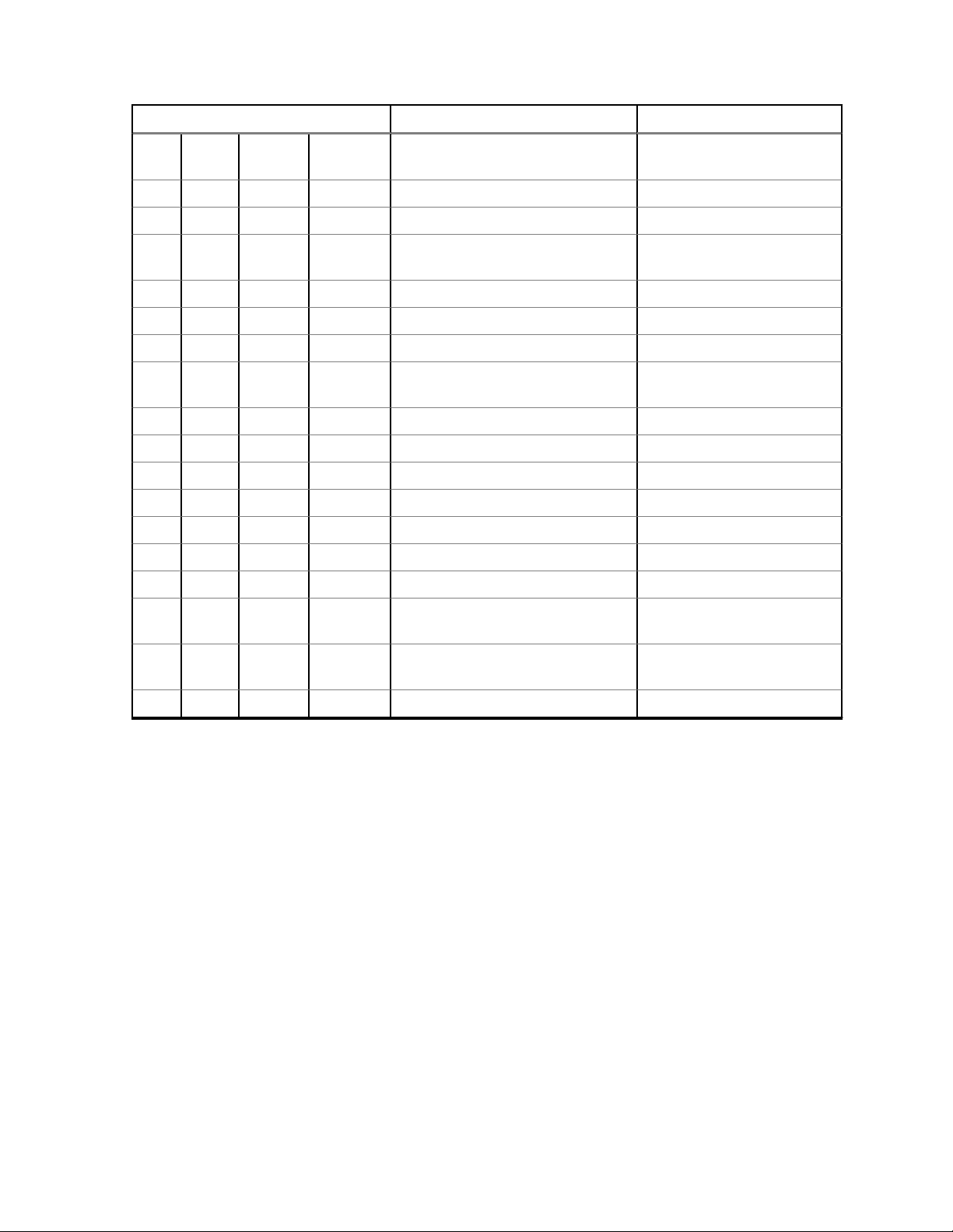
MN002211A01-AE
Chapter 5: Disassembly/Reassembly Procedures
Label Description Part Number
10 Back Kit Refer to Additional Parts
List on page 92
10.1 Main Board Assembly Part of Back Kit
10.2 Chassis Assembly PMLN7273_
10.2.1 M2 Screw (Main Board Assem-
03012034001
bly)
10.2.2 Top Control Seal 32012269001
10.2.3 Thermal Pad 75012234001
10.2.4 Battery Contact Seal 32012110001
10.2.5 Chassis (With dispensed O-
0104067J11
Ring)
10.2.5.1
Chassis Left Label LB000706A01
10.2.5.2 Chassis Right Label LB000706A02
11 Front Kit-Back Kit Screw 0316281H01
12 Compro Label LB000560A01
13 Ventilation Seal 3286058L01
14 Ventilation Label LB000256A01
15 TIA Label Non-field replaceable
16 Battery Refer to Additional Parts
List on page 92
17 Belt Clip Refer to Additional Parts
List on page 92
18 RTTE Label 5486749Z01
89
Page 90
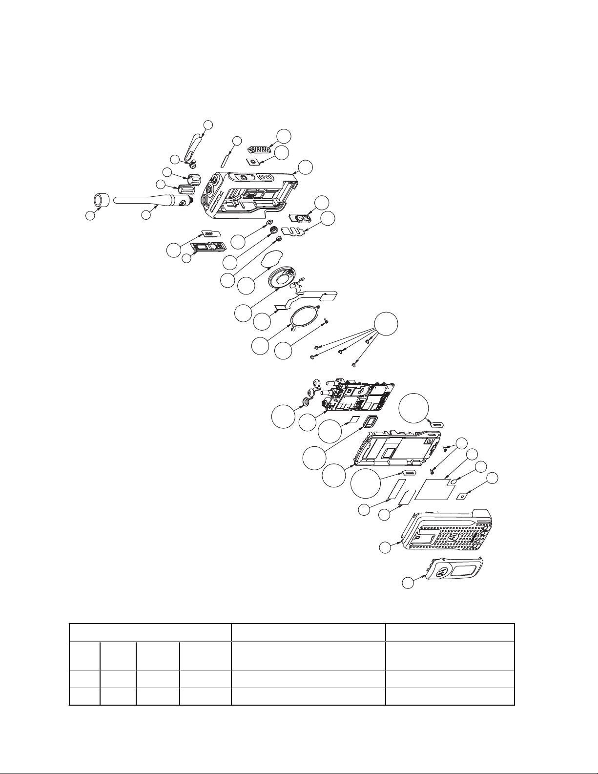
17
16
18
15
10.2.5.1
10.2.5
10.2.4
10.2.3
10.1
9.14
9.13
9.12
9.11
9.10
9.9
9.8
9.7
8
9.6
7
6
5
4
3
2
1
9.5
9.4
9.3
9.2
9.1
10.2.1
10.2.5.2
11
12
13
14
10.2.2
MN002211A01-AE
Chapter 5: Disassembly/Reassembly Procedures
5.8.2
Non-Keypad Model
Figure 65: Non-Keypad Model Exploded View
List on page 92
Table 35: Non-Keypad Model Exploded View Parts List
Item Description Part Number
1 Nameplate (Product Number) Refer to Additional Parts
2 Nameplate (Motorola Solutions) 33012026001
3 RF Plug 38012018001
90
Page 91

MN002211A01-AE
Chapter 5: Disassembly/Reassembly Procedures
Item Description Part Number
4 Volume Knob 36012016001
5 Channel Knob 36012017001
6 Antenna ID Band Refer to Additional Parts
List on page 92
7 Antenna Refer to
Additional Parts
List on page 92
8 Aesthetic Cover 0104058J40
9 Front Cover Kit PMLN7272_
9.1 PTT Retainer 42012035001
9.2 Side Button KP000087A01
9.3 Housing Assembly 0104067J10
9.4 PTT Keypad KP000086A01
9.5 PTT Paddle HN000696A01
9.6 UC Escutcheon 33012020001
9.7 Microphone Membrane SL000209A01
9.8 Microphone Boot SL000208A01
9.9 Microphone 50012012001
9.10 Speaker Mesh HW000738A01
9.11 Speaker AC000028A02
9.12 UC-Audio Flex PF001006A01
9.13 Speaker Retainer 42012044001
9.14 K18 Screw (Keypad-Display
0385273D06
Retainer and Speaker Retainer)
10 Back Kit Refer to Additional Parts
List on page 92
10.1 Main Board Assembly Part of Back Kit
10.2 Chassis Assembly PMLN7273_
10.2.1 M2 Screw (Main Board Assem-
03012034001
bly)
10.2.2 Top Control Seal 32012269001
10.2.3 Thermal Pad 7515526H01
10.2.4 Battery Contact Seal 32012110001
10.2.5 Chassis (With dispensed O-
0104067J11
Ring)
10.2.5.1 Chassis Left Label LB000706A01
10.2.5.2 Chassis Right Label LB000706A02
11 Front Kit-Back Kit Screw 0316281H01
12 Compro Label LB000560A01
13 Ventilation Seal 3286058L01
91
Page 92

MN002211A01-AE
Chapter 5: Disassembly/Reassembly Procedures
Item Description Part Number
14 Ventilation Label LB000256A01
15 TIA Label Non-field replaceable
16 Battery Refer to Additional Parts
List on page 92
17 Belt Clip Refer to
List on page 92
18 RTTE Label 5486749Z01
5.8.3
Additional Parts
Additional Parts List
This list consists of parts compatible to your radio.
Table 36: Batteries
Item Part Number
Core Slim Li-Ion 1500 mAH PMNN4406_
Core NIMH 1300 mAH PMNN4415_
IMPRES Li-Ion 1500 mAH PMNN4417_
IMPRES Li-Ion Non-FM 2150 mAH PMNN4418_
Core Li-Ion 2450 mAH IP68 PMNN4543_
Table 37: Nameplates
Item Part Number
DP 2400e 33012039027
DP 2600e 33012039028
Table 38: Back Kits
Item Part Number
Back Cover Kit, 136–174 MHz, 5 W, Limited
Keypad Portable
Back Cover Kit, 136–174 MHz, 5 W, Limited
Keypad Portable
Back Cover Kit, 136–174 MHz, 5 W, Non-Keypad Portable
Back Cover Kit, 300–360 MHz, 4 W, Non-Keypad Portable
Back Cover Kit, 350–400 MHz, 4 W, Limited
Keypad Portable
Back Cover Kit, 350–400 MHz, 4 W, Limited
Keypad Portable
PMLD4733_S
PMLD4734_S
PMLD4737_S
PLMLD4749_
PMLD4755_S
PMLD4800_S
92
Page 93

Chapter 5: Disassembly/Reassembly Procedures
Item Part Number
MN002211A01-AE
Back Cover Kit, 350–400 MHz, 4 W, Non-Keypad Portable
Back Cover Kit, 300 MHz, Non-Keypad Portable
Back Cover Kit, 403–527 MHz, 4 W, Limited
Keypad Portable
Table 39: Antenna ID Band (in pack of 10 pieces)
Item Part Number
Grey 32012144001
Yellow 32012144002
Green 32012144003
Blue 32012144004
Purple 32012144005
Table 40: Belt Clips
Item Part Number
2 in. belt clip PMLN4651_
PMLD4799_S
PMLD4646_S
PMLE5074_S
2.5 in. belt clip PMLN7008_
5.9
Torque Chart
Torque Chart lists the various screws by part number and description, followed by the torque values in
different units of measure.
NOTICE: Torque all screws to the recommended value when assembling the radio.
Table 41: Torque Specifications for Screws
Part Number Description Driver/Socket Torque
lbs-in N-m
0385273D06
03012034001
K18 Screw
(Speaker Retainer)
K18 Screw (Keypad-Display Retainer)
M2 Screw
(Mainboard Assembly) - New
Chassis
T6 Torx 2.0 to 2.2 0.23 to 0.25
T6 Torx 1.5 to 1.7 0.17 to 0.19
T6 Torx 3.1 to 3.5 0.35 to 0.40
93
Page 94

MN002211A01-AE
Chapter 5: Disassembly/Reassembly Procedures
Part Number Description Driver/Socket Torque
lbs-in N-m
M2 Screw
(Mainboard Assembly) - Rework Chassis
0316281H01 Front Kit-Back
Kit Screw
T6 Torx 2.0 0.23
T6 Torx 2.1 to 2.3 0.24 to 0.26
94
Page 95

MN002211A01-AE
Basic Troubleshooting
Chapter 6
Basic Troubleshooting
This chapter contains error codes and board replacement procedures.
If the board does not pass all the performance checks in Transceiver Performance Testing on page 30
or exhibits an error code listed below, then the circuit board should be replaced. If repair requires
knowledge of details of component level troubleshooting, please send the radio to a Motorola Solutions
Service Center.
To access the various connector pins, use the housing eliminator/test fixture along with the diagrams
found in this section of the manual. See "Service Aids" for the appropriate Motorola Solutions service
aids and tools part numbers.
6.1
Replacement Back Cover Kit Procedures
Once a problem has been isolated to a specific board, install the appropriate back cover kit (Refer to
"Model Charts"), which is orderable from Motorola Solutions Radio Products and Solutions
Organization.
If a board is replaced, it does not necessarily need to be retuned if it has been factory tuned. It should
however be checked for performance before being placed into service. Of particular concern is the
Bias DAC, which will need to be set for the appropriate final device bias current prior to keying up the
radio. If the bias is not properly set it may cause damage to the transmitter.
CAUTION:
The Tuner Tool only allows the serial number of the blank board to be entered once. Be very
attentive during this procedure.
6.2
Power-Up Error Codes
Upon powering up, the radio performs certain tests to determine if its basic electronics and software
are in working order. Any error detected has an associated error code that is presented on the radio
display.
NOTICE: Power-Up error codes are only applicable to Display Models only.
These error codes are intended to be used by a service technician when the radio generates the SelfTest Fail Tone. If these tests are successfully completed, the radio will generate the Self-Test Tone.
NOTICE: Non-display radios emit only the Self-Test Fail Tone if it fails the self-test.
There are two classes of detectable errors: fatal and non-fatal.
Fatal errors
Normal radio operation is inhibited when your radio encounters fatal errors.
Fatal errors include hardware errors detected by the microprocessor and certain memory errors.
These memory errors include incorrect ROM checksum, incorrect RAM checksum, and incorrect
checksums of codeplug (Persistent Storage) blocks that contain operating parameters.
If the codeplug block operating parameters are corrupted, operation of the unit on the proper
frequency, system, and group are in question.
95
Page 96

MN002211A01-AE
Chapter 6: Basic Troubleshooting
Attempts to use this information could provide a false sense of security that others are receiving
your messages.
Non-fatal errors
Corrupted codeplug blocks of call IDs, or their associated aliases are considered non-fatal errors.
Normal communication is still possible, but the user may be inconvenienced.
Table 42: Types of Error Code
Error Code Description Error
Type
ERROR
01/02
Call ID or associated
aliases codeplug block
Non-Fatal Normal communication is still possible, but
checksum is wrong.
ERROR
01/22
FAIL 01/82 External Codeplug
Tuning Codeplug block
checksum is wrong.
Non-Fatal Normal communication is still possible.
Fatal Reprogram codeplug.
block checksum is
wrong.
FAIL 01/92 Secure Codeplug
Fatal Reprogram codeplug.
checksum error.
FAIL 01/A2 Tuning Codeplug block
Fatal Reprogram codeplug.
checksum is wrong.
FAIL 01/81 ROM Checksum is
Fatal Reprogram FLASH Memory, then retest.
wrong.
FAIL 01/88 Radio RAM test fail-
Fatal Retest radio by turning it off and turning it
ure.
FAIL 01/90
or FAIL
General hardware test
failure.
Fatal Retest radio by turning it off and turning it
02/90
Corrective Action
the user may be inconvenienced.
Reprogram codeplug.
on again.
on again.
FAIL 02/81 DSP ROM Checksum
Fatal Reprogram FLASH Memory, then retest.
is wrong.
FAIL 02/82 DSP RAM1 test fail-
ure.
FAIL 02/84 DSP RAM2 test fail-
ure.
Fatal Retest radio by turning it off and turning it
on again.
Fatal Retest radio by turning it off and turning it
on again.
FAIL 02/88 DSP RAM test failure. Fatal Retest radio by turning it off and turning it
on again.
FAIL 02/C0 DSP ROM Checksum
is wrong.
No Display Display module is not
connected properly.
Display module is
Fatal Retest radio by turning it off and turning it
on again.
Fatal Check connection between main board and
display module. Replace with new display
module.
damaged.
NOTICE:
If error message reoccurs, replace main board or send radio to nearest Motorola Solutions
Depot.
96
Page 97

MN002211A01-AE
Chapter 6: Basic Troubleshooting
6.3
Operational Error Codes
During radio operation, your radio performs dynamic tests to determine if your radio is working
properly. Problems detected during these tests are presented as error codes on your radio display.
Use the following table to aid in understanding particular operational error codes.
Table 43: Types of Error Code
Error
Code
FAIL
001
FAIL
002
Description Error Type Corrective Action
Synthesizer Out-of-Lock. Non-fatal Reprogram the codeplug. Refer
to Detailed Service Manual.
Personality checksum or
system block error.
NOTICE: If error message reoccurs, send radio to nearest Motorola Solutions Service Centers
or Authorized Motorola Solutions Service Dealers.
Non-fatal Reprogram the codeplug.
97
Page 98

MN002211A01-AE
Appendix A:
EMEA Regional Warranty, Service, and Technical Support
Appendix A
EMEA Regional Warranty, Service,
and Technical Support
Warranty and Service Support
Motorola Solutions offers long-term support for its products. This support includes full exchange and/or
repair of the product during the warranty period and service/repair or spare parts support out of
warranty. Any "return for exchange" or "return for repair" by an authorized Motorola Solutions Dealer
must be accompanied by a Warranty Claim Form. Warranty Claim Forms are obtained by contacting
an Authorized Motorola Solutions Dealer.
Warranty Period and Return Instructions
The terms and conditions of warranty are defined fully in the Motorola Solutions Dealer or Distributor or
Reseller contract. These conditions may change from time to time and the following notes are for
guidance purposes only.
In instances where the product is covered under a "return for replacement" or "return for repair"
warranty, a check of the product should be performed prior to shipping the unit back to Motorola
Solutions. This is to ensure that the product has been correctly programmed or has not been subjected
to damage outside the terms of the warranty.
Prior to shipping any radio back to the appropriate Motorola Solutions warranty depot, please contact
Customer Resources. All returns must be accompanied by a Warranty Claim Form, available from your
Customer Services representative. Products should be shipped back in the original packaging, or
correctly packaged to ensure no damage occurs in transit.
After Warranty Period
After the Warranty period, Motorola Solutions continues to support its products in two ways:
• Motorola Solutions Managed Technical Services (MTS) offers a repair service to both end users
and dealers at competitive prices.
• MTS supplies individual parts and modules that can be purchased by dealers who are technically
capable of performing fault analysis and repair.
Further Assistance
You can also contact the Customer Help Desk through http://www.motorolasolutions.com.
98
Page 99

MN002211A01-AE
Service Information
Appendix B
Service Information
EMEA Technical Support Operations (TSO)
The EMEA Technical Support Operations (TSO) provides a remote Technical Support Service to help
customers resolve technical issues and quickly restore networks and systems. This team of highly
skilled professionals is available to customers with current service agreements in place that include the
Technical Support Service. The TSO technical experts may be accessed through the Service Desk
either electronically or using the listed telephone numbers. If you are unsure whether your current
service agreement entitles you to benefit from this service, or if you would like more information about
the Technical Support Service, contact your local customer support or account manager for further
information.
Contact Details
Email: techsupport.emea@motorolasolutions.com
Table 44: List of Telephone Numbers
Country In Country Number to Dial
AUSTRIA 0800 281 195
DENMARK 80 253 546
FRANCE 0800 914 532 or +33 176 775 609
GERMANY 0800 724 6872 or +49 69 22221568
ISRAEL 180 931 5818
ITALY 800 791 276
NETHERLANDS 0800 0249 893
NORWAY 800 14 802
POLAND 00800 1215 772
RUSSIA 810 800 286 15011
SAUDI ARABIA 800 811 0523
SOUTH AFRICA 0800 994 886
SPAIN 9009 416 84
UNITED KINGDOM 0800 731 3496 or +44 207 019 0461
UNITED ARAB EMIRATES 8000 3570 4387
All Other Countries +44 207 019 0461
European Systems Component Centre (ESCC)
The European Systems Component Centre provides a repair service for infrastructure equipment.
Customers requiring repair service should contact the Customer Information Desk to obtain a Return
Material Authorization number. The equipment should then be shipped to the following address unless
advised otherwise.
99
Page 100

MN002211A01-AE
Appendix B:
Motorola Solutions GmbH, European Systems Component Centre, Am Borsigturm 130,13507 Berlin,
Germany
Service Information
Contact Details
• E-Mail:
• Telephone: +49 (0) 30 66861404
• Telefax: +49 (0) 30 66861426
• Monday – Friday 08:00 am to 06:00 pm (CET)
escc.admin@motorolasolutions.com
European Radio Support Centre (ERSC)
ERSC provides a remote Technical Support Service to help customers resolve technical issues and
quickly restore their systems. The centre handles service orders for subscribers and accessories. This
team of highly skilled professionals is available to the customers that have current ERSC service
agreements in place. For further information and to verify if your current service agreement entitles you
to benefit from this service, contact your local customer support.
Contact Details
• E-Mail: ersc.admin@motorolasolutions.com
• Telephone: +49 (0) 30 66861555
• Telefax: +49 (0) 30 66861579
Parts Identification and Ordering
If you need help in identifying non-referenced spare parts, direct a request to the Customer Care
Organization of a local area Motorola Solutions representative. Orders for replacement parts, kits, and
assemblies should be placed directly at the local distribution organization of Motorola Solutions or
through the Extranet site Motorola Online at https://emeaonline.motorolasolutions.com.
Updated Versions of Manuals
Verify the current version of the manual at our Extranet site, Motorola Online: https://
emeaonline.motorolasolutions.com.
Your Input
Send questions and comments regarding user documentation to
documentation@motorolasolutions.com.
100
 Loading...