

MOTOTRBO
TM
TWO-WAY RADIOS
TM
DP1400
BASIC SERVICE
MANUAL


Foreword
This manual covers all models of the DP series Portable Radios, unless otherwise specified. It includes all the information
necessary to maintain peak product performance and maximum working time, using levels 1 and 2 maintenance
procedures. This level of service goes down to the board replacement level and is typical of some local service centers,
self-maintained customers, and distributors.
RF Energy Exposure and Product Safety Guide for Portable Two-Way Radios
ATTEN TION!
Before using the portable two way product, DP1400 , read the RF Energy Exposure and Safety guide
that ships with the radio which contains important operating instructions for safe usage and RF energy
awareness and control for Compliance with applicable Standards and Regulations.
Computer Software Copyrights
The Motorola products described in this manual may include copyrighted Motorola computer programs stored in
semiconductor memories or other media. Laws in the United States and other countries preserve for Motorola certain
exclusive rights for copyrighted computer programs, including, but not limited to, the exclusive right to copy or reproduce in
any form the copyrighted computer program. Accordingly, any copyrighted Motorola computer programs contained in the
Motorola products described in this manual may not be copied, reproduced, modified, reverse-engineered, or distributed in
any manner without the express written permission of Motorola. Furthermore, the purchase of Motorola products shall not
be deemed to grant either directly or by implication, estoppel, or otherwise, any license under the copyrights, patents or
patent applications of Motorola, except for the normal non-exclusive license to use that arises by operation of law in the
sale of a product.
i
Document Copyrights
No duplication or distribution of this document or any portion thereof shall take place without the express written permission
of Motorola. No part of this manual may be reproduced, distributed, or transmitted in any form or by any means, electronic
or mechanical, for any purpose without the express written permission of Motorola.
Disclaimer
The information in this document is carefully examined, and is believed to be entirely reliable. However, no responsibility is
assumed for inaccuracies. Furthermore, Motorola reserves the right to make changes to any products herein to improve
readability, function, or design. Motorola does not assume any liability arising out of the applications or use of any product
or circuit described herein; nor does it cover any license under its patent rights nor the rights of others.
Trademarks
MOTOROLA, MOTO, MOTOROLA SOLUTIONS and the Stylized M logo are trademarks or registered trademarks of
Motorola Trademark Holdings, LLC and are used under license. All other trademarks are the property of their respective
owners.
© 2014 Motorola Solutions, Inc.
All rights reserved.

ii
Notes

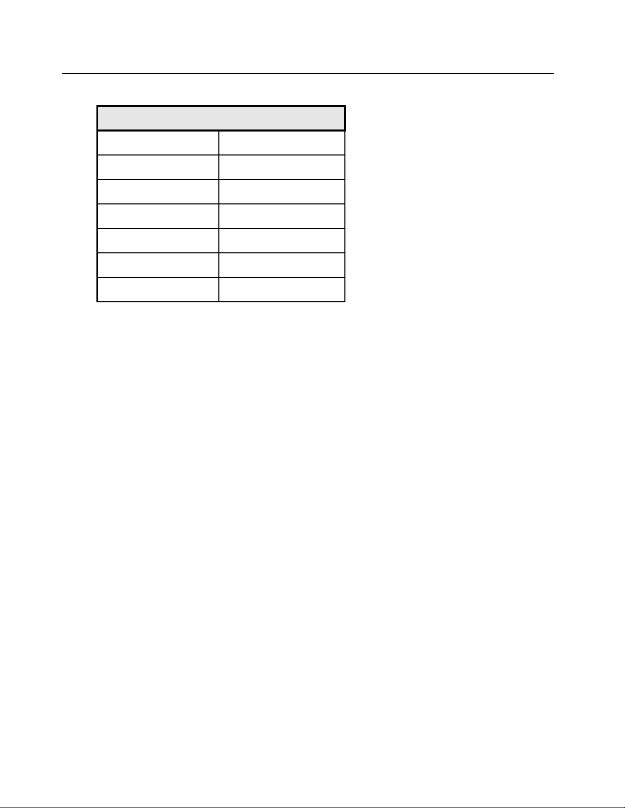
Document History
The following major changes have been implemented in this manual since the previous edition:
Edition Description Date
iii
68012008074-A
68012008074-B
Initial Release June 2013
Added GOB information Jan. 2015

iv
Notes

Table of Contents v
Table of Contents
Foreword..........................................................................................................i
......................................................................................................................................................................i
RF Energy Exposure and Product Safety Guide for Portable Two-Way Radios ..........................................i
Computer Software Copyrights ....................................................................................................................i
Document Copyrights ...................................................................................................................................i
Disclaimer.....................................................................................................................................................i
Trademarks ..................................................................................................................................................i
Document History ........................................................................................ iii
Chapter 1 Introduction ......................................................................... 1-1
1.1 Notations Used in This Manual .................................................................................................... 1-1
1.2 Radio Description ........................................................................................................................ 1-1
1.2.1 Non Keypad Model .......................................................................................................... 1-2
1.3 .Portable Radio Model Numbering Scheme ................................................................................ 1-3
1.4 Model Charts ............................................................................................................................... 1-4
1.4.1 VHF Model Chart............................................................................................................. 1-4
1.4.2 UHF Model Chart............................................................................................................. 1-5
1.5 Specifications............................................................................................................................... 1-6
Chapter 2 Test Equipment and Service Aids ..................................... 2-1
2.1 Recommended Test Equipment .................................................................................................. 2-1
2.2 Service Aids................................................................................................................................. 2-2
2.3 Portable Programming Cable ...................................................................................................... 2-3
2.4 Portable Test Cable ..................................................................................................................... 2-5
Chapter 3 Transceiver Performance Testing ..................................... 3-1
3.1 General ........................................................................................................................................ 3-1
3.2 Setup ........................................................................................................................................... 3-1
3.2.1 RF Test Mode.................................................................................................................. 3-2
3.3 Test Mode .................................................................................................................................... 3-7
3.3.1 Entering Test Mode .........................................................................................................3-7
3.3.2 RF Test Mode.................................................................................................................. 3-7
3.3.3 LED Test Mode................................................................................................................ 3-7
3.3.4 Speaker Tone Test Mode ................................................................................................ 3-7
3.3.5 Earpiece Tone Test Mode ............................................................................................... 3-8
3.3.6 Audio Loopback Earpiece Test Mode.............................................................................. 3-8
3.3.7 Battery Check Test Mode ................................................................................................ 3-8
3.3.8 Button/Knob/PTT Test Mode ........................................................................................... 3-8
Chapter 4 Radio Programming and Tuning ....................................... 4-1

vi Table of Contents
4.1 Introduction .................................................................................................................................. 4-1
4.2 Customer Programming Software Setup ..................................................................................... 4-1
4.3 AirTracer Application Tool............................................................................................................ 4-2
4.4 Radio Tuning Setup ..................................................................................................................... 4-2
Chapter 5 Disassembly/Reassembly Procedures ............................. 5-1
5.1 Introduction .................................................................................................................................. 5-1
5.2 Preventive Maintenance .............................................................................................................. 5-1
5.2.1 Inspection ........................................................................................................................ 5-1
5.2.2 Cleaning Procedures ....................................................................................................... 5-1
5.3 Safe Handling of CMOS and LDMOS Devices ............................................................................ 5-2
5.4 Repair Procedures and Techniques – General............................................................................ 5-4
5.5 Disassembling and Reassembling the Radio — General ............................................................ 5-5
5.6 Radio Disassembly – Detailed ..................................................................................................... 5-6
5.6.1 Front Cover from Chassis Disassembly .......................................................................... 5-6
5.6.2 Generic Option Board (GOB) Disassembly ................................................................... 5-12
5.6.3 Chassis Disassembly..................................................................................................... 5-16
5.6.4 Speaker and Microphone Disassembly ......................................................................... 5-17
5.6.5 Audio Jack Dust Cover Disassembly............................................................................. 5-18
5.6.6 Micro USB Dust Cover Disassembly ............................................................................. 5-20
5.7 Radio Reassembly - Detailed .................................................................................................... 5-22
5.7.1 Micro USB Dust Cover Reassembly.............................................................................. 5-22
5.7.2 Audio Jack Dust Cover Reassembly ............................................................................. 5-23
5.7.3 Speaker and Microphone Reassembly.......................................................................... 5-24
5.7.4 Chassis Reassembly ..................................................................................................... 5-25
5.7.5 Generic Option Board (GOB) Reassembly.................................................................... 5-29
5.7.6 Chassis and Front Housing Reassembly....................................................................... 5-33
5.8 Radio Exploded Mechanical View and Parts Lists ..................................................................... 5-36
5.8.1 Non Option Board .......................................................................................................... 5-36
5.8.2 Option Board Capable ................................................................................................... 5-39
5.8.3 Torque Chart.................................................................................................................. 5-42
Chapter 6 Basic Troubleshooting ....................................................... 6-1
6.1 Introduction .................................................................................................................................. 6-1
6.2 Replacement Back Cover Kit Procedures.................................................................................... 6-1
Appendix A EMEA Regional Warranty, Service and Technical Support ..
A-1
A.1 Warranty and Service Support.....................................................................................................A-1
A.1.1 Warranty Period and Return Instructions.........................................................................A-1
A.1.2 After Warranty Period ......................................................................................................A-1
A.2 European Radio Support Centre (ERSC) ....................................................................................A-2
A.3 Piece Parts...................................................................................................................................A-2
A.4 Technical Support ........................................................................................................................A-3
A.5 Further Assistance From Motorola...............................................................................................A-3
Appendix B Limited Level 3 Servicing ...................................................B-1

Table of Contents vii
B.1 Maintenance ................................................................................................................................B-1
B.2 Chip Components ........................................................................................................................ B-1
B.3 Component and Parts list ............................................................................................................B-2
Glossary.........................................................................................Glossary-1

viii List of Figures
List of Figures
Figure 1-1. Non Keypad Model............................................................................................................... 1-2
Figure 1-2. Portable Radio Model Numbering Scheme .......................................................................... 1-3
Figure 2-1. Portable Programming Cable with TTR (PMKN4128_)........................................................ 2-3
Figure 2-2. Portable Test Cable (PMKN4156_ ) .....................................................................................2-5
Figure 4-1. CPS Programming Setup ..................................................................................................... 4-1
Figure 4-2. Radio Tuning Equipment Setup ........................................................................................... 4-2
Figure 5-1. Battery Removal................................................................................................................... 5-6
Figure 5-2. Channel Selector and Volume Knob Removal ..................................................................... 5-7
Figure 5-3. Chassis Removal ................................................................................................................. 5-8
Figure 5-4. Chassis Removal from Front Housing ................................................................................. 5-9
Figure 5-5. Audio Jack Shroud Assembly Removal ............................................................................. 5-10
Figure 5-6. Speaker and Microphone Wires Removal.......................................................................... 5-11
Figure 5-7. Unlatching the Actuator ...................................................................................................... 5-13
Figure 5-8. Actuator on Mainboard ....................................................................................................... 5-14
Figure 5-9. Option Board Flex Removal ............................................................................................... 5-14
Figure 5-10. Option Board Disassembly................................................................................................. 5-15
Figure 5-11. Flex Removal ..................................................................................................................... 5-15
Figure 5-12. Chassis Disassembly ......................................................................................................... 5-16
Figure 5-13. Speaker and Microphone Disassembly.............................................................................. 5-17
Figure 5-14. Dust Cover Disassembly.................................................................................................... 5-18
Figure 5-15. Audio Jack Dust Cover Removal .......................................................................................5-19
Figure 5-16. Prying the Micro USB Dust Cover...................................................................................... 5-20
Figure 5-17. Micro USB Dust Cover Removal ........................................................................................5-21
Figure 5-18. Micro USB Dust Cover Reassembly .................................................................................. 5-22
Figure 5-19. Audio Jack Dust Cover Reassembly .................................................................................. 5-23
Figure 5-20. Speaker and Microphone Reassembly .............................................................................. 5-24
Figure 5-21. Battery Contact Seal Assembly.......................................................................................... 5-25
Figure 5-22. Thermal Pad Assembly ...................................................................................................... 5-26
Figure 5-23. PCB and Top Control Seal Assembly................................................................................. 5-27
Figure 5-24. Poron Pad Alignment ......................................................................................................... 5-28
Figure 5-25. Complete Option Board Assembly ..................................................................................... 5-29
Figure 5-26. Folding the Flex.................................................................................................................. 5-30
Figure 5-27. Chassis and Front Housing Reassembly ........................................................................... 5-33
Figure 5-28. Audio Jack Shroud Reassembly ........................................................................................5-34
Figure 5-29. Inserting Chassis Assembly into Housing .......................................................................... 5-35
Figure B-1. PCB Top View ......................................................................................................................B-2

List of Tables ix
List of Tables
Table 1-1. Radio Frequency Ranges and Power Levels....................................................................... 1-1
Table 2-1. Recommended Test Equipment ........................................................................................... 2-1
Table 2-2. Service Aids ......................................................................................................................... 2-2
Table 2-3. Pin Configuration of Portable Programming Cable with TTR............................................... 2-4
Table 2-4. Pin Configuration of Portable Test Cable ............................................................................. 2-6
Table 3-1. Initial Equipment Control Settings ........................................................................................ 3-1
Table 3-2. Test Environments................................................................................................................ 3-2
Table 3-3. Test Frequencies.................................................................................................................. 3-3
Table 3-4. Transmitter Performance Checks ........................................................................................3-4
Table 3-5. Receiver Performance Checks ............................................................................................ 3-5
Table 4-1. Software Installation Kits Radio Tuning Setup ..................................................................... 4-1
Table 5-1. Lead Free Solder Wire Part Number List............................................................................. 5-4
Table 5-2. Lead Free Solder Paste Part Number List ........................................................................... 5-4
Table 5-3. Exploded View Part List ..................................................................................................... 5-37
Table 5-4. Exploded View Part List ..................................................................................................... 5-40
Table 5-5. Front Housing Service Kits................................................................................................. 5-41
Table 5-6. Back Cover Kit Part Numbers ............................................................................................ 5-41
Table 5-7. Torque Specifications for Screws ....................................................................................... 5-42

x Related Publications
Related Publications
Product Safety and RF Exposure ................................................................................................ 6864117B25
DP1400 User Guide................................................................................................................... 68012008075
DP1400 Quick Reference Guide................................................................................................ 68012008076

Introduction: Notations Used in This Manual 1-1
!
C a u t i o n
Chapter 1 Introduction
1.1 Notations Used in This Manual
Throughout the text in this publication, you will notice the use of note and caution notations. These
notations are used to emphasize that safety hazards exist, and due care must be taken and
observed.
NOTE
An operational procedure, practice, or condition that is essential to emphasize.
CAUTION indicates a potentially hazardous situation which, if
not avoided, might result in equipment damage.
WARNING indicates a potentially hazardous situation
which, if not avoided, could result in death or injury.
1.2 Radio Description
The DP1400 portable radios are available in the following frequency ranges and power levels.
Table 1-1. Radio Frequency Ranges and Power Levels
Frequency Band Bandwidth Power Level
VHF 136–174 MHz 1 Watt or 5 Watt
UHF 403–470 MHz 1 Watt or 4 Watt
These digital radios are among the most sophisticated two-way radios available. They have a robust
design for radio users who need high performance, quality, and reliability in their daily
communications. This architecture provides the capability of supporting a multitude of legacy and
advanced features resulting in a more cost-effective two-way radio communications solution.
1-2 Introduction: Radio Description
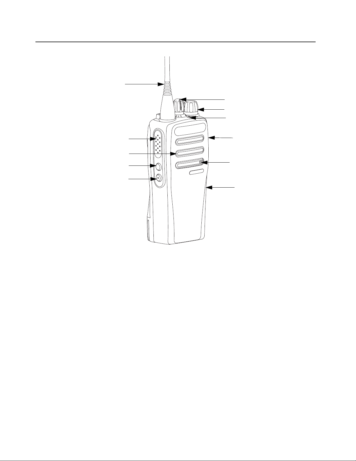
Antenna
Channel Selector Knob
On/Off Volume Control Knob
Push-to-Talk (PTT) Button
Side Button 2 (Programmable)
LED Indicator
Speaker
Microphone
USB with Dust Cover
Side Button 1 (Programmable)
Accesory Connector
with Dust Cover
1.2.1 Non Keypad Model
• ON/OFF/VOLUME KNOB – Rotate clockwise until click is heard to turn on radio; rotate counterclockwise until click is heard to turn off radio. Rotate clockwise to increase volume level; rotate
counter-clockwise to decrease volume level.
• LED INDICATOR – Red, green and orange light-emitting diodes indicate operating status.
• SIDE BUTTONS – These 2 buttons are field programmable using the CPS.
• CHANNEL SELECTOR KNOB – Rotate clockwise to increment and counter clockwise to
decrement the channel.
• PUSH-TO-TALK (PTT) – Press to execute voice operations (e.g. Group call and Private Call).
• ANTENNA – Provides the needed RF amplification when transmitting or receiving.
• MICROPHONE – Allows the voice to be sent when PTT or voice operations are activated.
• ACCESSORY CONNECTOR WITH DUST COVER – Interface point for all accessories to be
used with the radio. It has eight points to which specific accessories will connect to and be
activated.
• SPEAKER – Outputs all tones and audio that are generated by the radio (e.g. features like
keypad tones and voice audio).
• USB WITH DUST COVER – Dust cover to prevent dust from clogging USB port.
Figure 1-1. Non Keypad Model

Introduction: .Portable Radio Model Numbering Scheme 1-3
Model No.Example : AZ H 5 5 Q D H 9 L A 1 A N
Position : 1 2 3 4 5 6 7 8 9 10 11 12
Unique Variation
N: Standard Package
Version Letter
Feature Level
1: Standard w/ FM
2. Non-FM
3. CSA IE CEx ATEX
4. CQST
Primary System Type
A: Conventional
B: Trunking
C: Analog Only
Primary Operation
Channel Information
8: Variable/Programmable Channel Spacing
w/ unique # of channels
9: Variable/Programmable Channel Spacing
Power Level
C: 1.0,2.0,2.5 or 3.5 Watt
D: 4.0-5.0 Watt
Band
J: 136-174 MHz
R: 403-470 MHz
Physical Packages
C: Low Tier (Plain)
H: Mid Tier (Monochrome Display LKP)
N: HIgh Tier (Color Display FKP)
J: 3 Button MOR
T: No Display - Limited Tier
H: Portable
AZ: Asia
LA: Latin America
AA: North America
MD: Europe/Middle East/Africa
J
K
L
M
N
:
:
:
:
:
Basic (No GPS, no Bluetooth, no
embedded GOB)
GPS and Bluetooth
GPS Only
Bluetooth Only
Bluetooth w/ embedded GOB
MOTOTRBO DP1400: 01
1.3 .Portable Radio Model Numbering Scheme
Figure 1-2. Portable Radio Model Numbering Scheme
1-4 Introduction: Model Charts
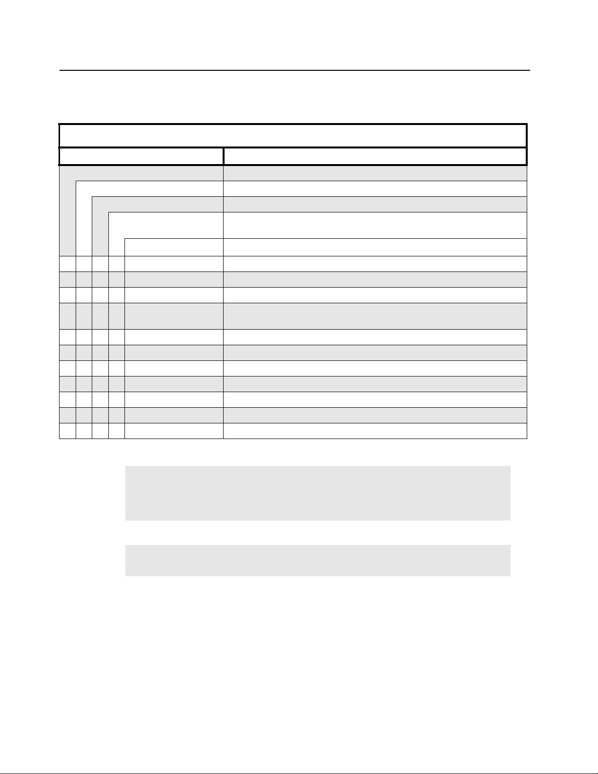
1.4 Model Charts
1.4.1 VHF Model Chart
DP1400 Series, VHF, 136–174 MHz
Model Description
MDH01JDC9JA2_N DP1400 136–174 MHz, 5W, Non Keypad
MDH01JDC9JC2_N DP1400 136–174 MHz, 5W, Non Keypad, Analog
MDH01JDC9JE2_N DP1400 136–174 MHz, 5W, Non Keypad, Option Board Capable.
MDH01JDC9JF2_N DP1400 136–174 MHz, 5W, Non Keypad, Option Board Capable,
Analog
Item Description
X WAED4508_ BC Kit 136–174 MHz, 5W, Non Keypad
X WAED4507_ BC Kit 136–174 MHz, 5W, Non Keypad, Analog
X WAED4529_ BC Kit 136–174 MHz, 5W, Non Keypad, Option Board Capable
X WAED4530_ BC Kit 136–174 MHz, 5W, Non Keypad, Option Board Capable,
Analog
X X PMLN6345_ Front Cover Kit, Non Keypad
X X PMLN7210_ Front Cover Kit, Non Keypad, Option Board Capable
X X PMLN7228_ Option Board Installation Kit
X X X X HAD9742_ VHF Stubby, 146–162 MHz
X X X X HAD9743_ VHF Stubby, 162–174 MHz
X X X X NAD6502_R VHF Heliflex, 146–174 MHz
X X X X PMAD4012_ VHF Heliflex136–155 MHz
NOTE
NOTE
X = Item Included
_ = the latest version kit. When ordering a kit, refer to your specific kit for the suffix
number.
Analog model radios that are upgraded to digital with a license key will need to request
for Analog Service Kit.
Introduction: Model Charts 1-5
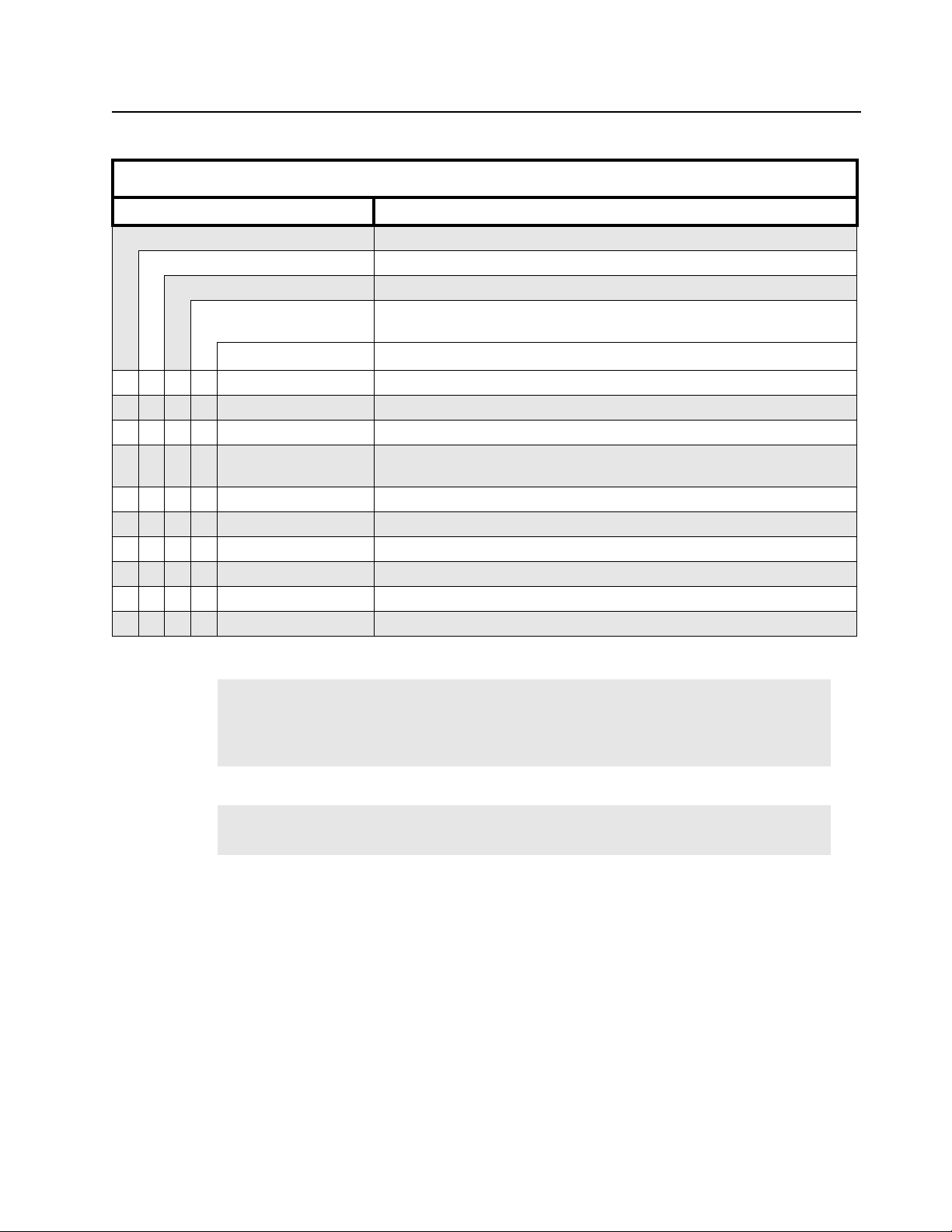
1.4.2 UHF Model Chart
DP1400 Series, UHF, 403–470 MHz
Model Description
MDH01QDC9JA2_N DP1400 403–470 MHz, 5W, Non Keypad
MDH01QDC9JC2_N DP1400 403–470 MHz, 5W, Non Keypad, Analog
MDH01QDC9JE2_N DP1400 403–470 MHz, 5W, Non Keypad, Option Board Capable
MDH01QDC9JF2_N DP1400 403–470 MHz, 5W, Non Keypad, Option Board Capable,
Analog
Item Description
X WAEE4472_ BC Kit 403–470 MHz, 4W, Non Keypad
X WAEE4471_ BC Kit 403–470 MHz, 4W, Non Keypad, Analog
X WAEE4499_ BC Kit 403–470 MHz, 5W, Non Keypad, Option Board Capable
X WAEE4500_ BC Kit 403–470 MHz, 5W, Non Keypad, Option Board Capable,
Analog
X X PMLN6345_ Front Cover Kit, Non Keypad
X X PMLN7210_ Front Cover Kit, Non Keypad, Option Board Capable
X X PMLN7228_ Option Board Installation Kit
X X X X PMAE4016_ UHF Whip Antenna (430–470MHz)
X X X X PMAE4002_ UHF 9cm Stubby Antenna (403–433MHz)
X X X X PMAE4003_ UHF 9cm Helical Antenna (430–470MHz)
NOTE
NOTE
X = Item Included
_ = the latest version kit. When ordering a kit, refer to your specific kit for the suffix
number.
Analog model radios that are upgraded to digital with a license key will need to request
for Analog Service Kit.
1-6 Introduction: Specifications
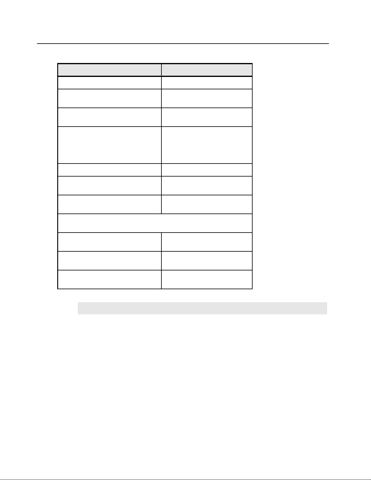
1.5 Specifications
General DP1400
Channel Capacity 16
Frequency VHF: 136 – 174 MHz
UHF: 403 – 470 MHz
Dimensions (HxWxT) w/ NiMH
battery
Weight
(with NiMH 1400 mAh)
(with Slim Li-Ion 1600 mAh battery)
(with High Cap Li-Ion 2200 mAh
battery)
Power Supply 7.5V (nominal)
FCC Description VHF: ABZ99FT3092
IC Description VHF: 109AB-99FT3092
Average battery life at 5/5/90 duty cycle with battery saver enabled in
carrier squelch and transmitter in high power.
NiMH 1400 mAh battery Analog: 9 hours
Core Slim Li-Ion 1600 mAh battery Analog: 10.5 hours
High Cap Li-Ion 2200 mAh battery Analog: 14.5 hours
130mm x 62.5mm x 42mm
406 g
341 g
346 g
UHF: ABZ99FT4094
UHF: 109AB-99FT4094
Digitial: 11.5 hours
Digital: 13.5 hours
Digital: 18.5 hours
NOTE
Weight can have 5% margin of error
Introduction: Specifications 1-7
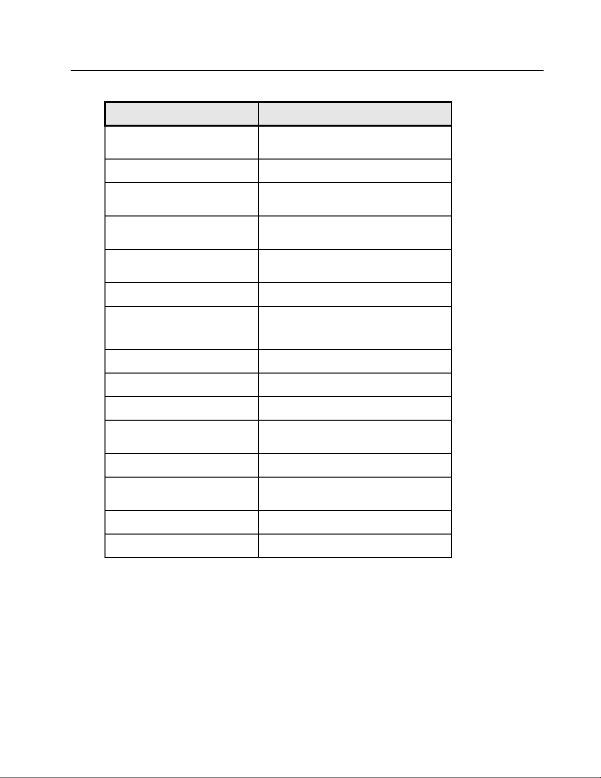
Receiver DP1400
Frequencies VHF: 136 – 174 MHz
UHF: 403 – 470MHz
Channel Spacing 12.5 kHz/ 20 kHz/ 25 kHz
Frequency Stability (-30°C to
+/-0.5 ppm
+60°C, +25 °C Ref)
Analog Sensitivity (12 dB SINAD) 0.3 µV
0.22 µV (typical)
Digital Sensitivity (5% BER) 0.25 µV
0.19 µV (typical)
Intermodulation (TIA603C) 70 dB
Adjacent Channel Selectivity
TIA603D 45 dB @ 12.5kHz
70 dB @ 20kHz/25kHz
Spurious Rejection (TIA603D) 70 dB
Rated Audio 0.5 W (internal)
Audio Distortion @ Rated Audio 5% (3% typical)
Hum and Noise -40 dB @ 12.5 kHz
-45 dB @ 20 kHz/ 25 kHz
Audio Response TIA603D
Conducted Spurious Emission
-57 dBm
(TIA603D)
Speaker Impedance 16 Ohms
Voltage @ Rated Audio 2.828 V
1-8 Introduction: Specifications
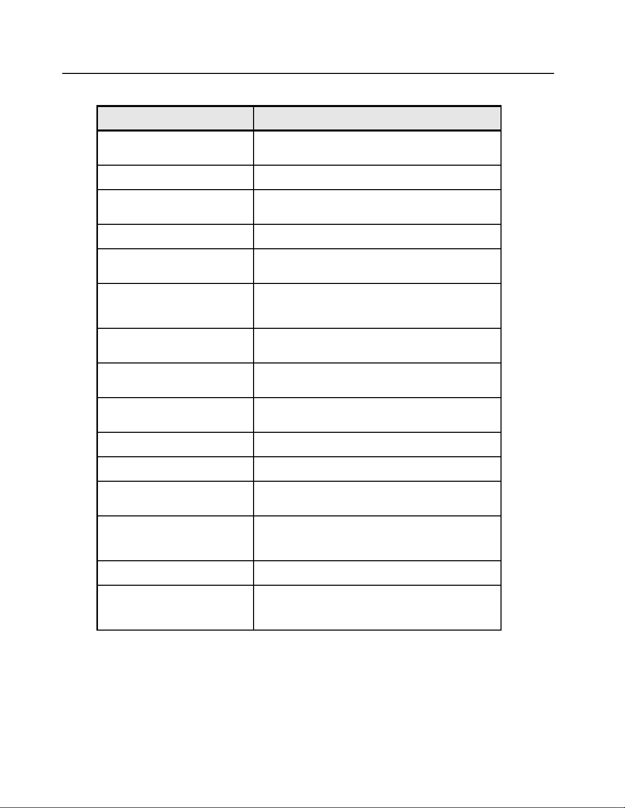
Transmitter DP1400
Frequencies VHF: 136 – 174 MHz
UHF: 403 – 470MHz
Channel Spacing 12.5 kHz/ 20 kHz/ 25 kHz
Frequency Stability (-30°C to
+/-0.5 ppm
+60°C, +25 °C Ref)
Power Output (Low Power) 1 W
Power Output (High Power) VHF: 5 W
UHF: 4 W
Modulation Limiting +/-2.5 kHz @ 12.5 kHz
± 4.0 kHz @ 20 kHz
+/-5.0 kHz @ 25 kHz
FM Hum and Noise -40 dB @ 12.5 kHz
-45 dB @ 20 kHz/ 25 kHz
Conducted / Radiated Emission -36 dBm < 1 GHz
-30 dBm > 1 GHz
Adjacent Channel Power 60 dB @ 12.5 kHz
70 dB @ 20/25 kHz
Audio Response TIA603D
Audio Distortion 3%(typical)
FM Modulation 12.5 kHz: 11K0F3E
25 kHz: 16K0F3E
4FSK Digital Modulation 12.5 kHz Data: 7K60F1D & 7K60FXD
12.5 kHz Voice: 7K60F1E & 7K60FXE
Combination of 12.5 kHz Data and Voice: 7K60F1W
Digital Vocoder Type AMBE+2™
Digital Protocol ETSI-TS102361-1
ETSI-TS102361-2
ETSI-TS102361-3
Conforms to:
ETSI TS 102 361 (Parts 1, 2 & 3) - ETSI DMR Standard
ETSI EN 300 086 - ETSI RF Specifications (Analog)
ETSI EN 300 113 - ETSI RF Specifications (Digital)
1999/5/EC (R&TTE - Radio and Telecommunications Terminal Equipment)
2002/95/EC (RohS - Banned Substances)
2002/96/EC (WEEE - Waste Electrical and Electronic Equipment)
94/62/EC (Packaging and Packaging Waste)
Radio meets applicable regulatory requirements.
Introduction: Specifications 1-9
VHF Self-Quieter Frequencies
144 MHz +/- 5 kHz
153.6 MHz +/- 5 kHz
UHF Self-Quieter Frequencies
420 MHz +/- 5 kHz
440 MHz +/- 5 kHz
172.8 MHz +/- 5 kHz
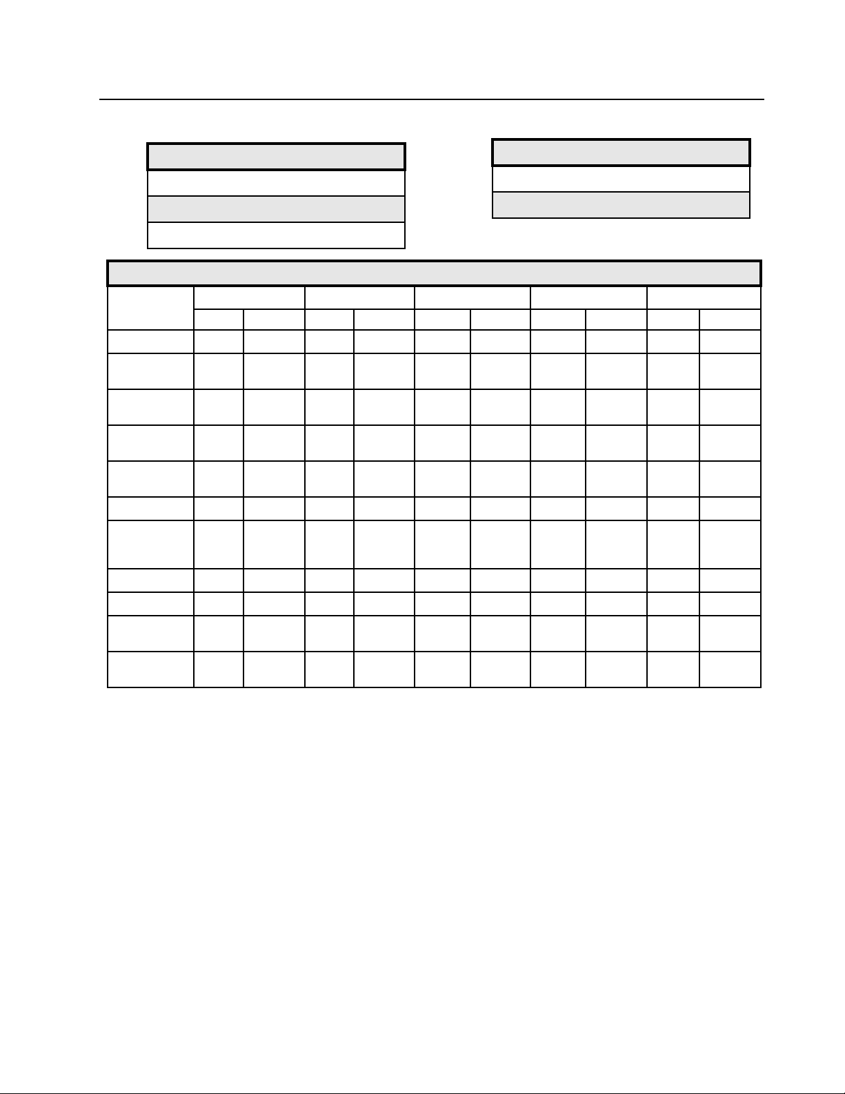
Military Standards
Applicable
MIL–STD
Low Pressure 500.1 I 500.2 II 500.3 II 500.4 II 500.5 II
High
Temperature
Low
Temperature
Temperature
Shock
Solar
Radiation
Rain 506.1 I, II 506.2 I, II 506.3 I,II 506.4 I, III 506.5 I, III
Humidity 507.1 II 507.2 II 507.3 II 507.4 – 507.5 II-
Salt fog 509.1 - 509.2 - 509.3 – 509.4 – 509.5 –
810C 810D 810E 810F 810G
Methods Procedures Methods Procedures Methods Procedures Methods Procedures Methods Prodecures
501.1 I, II 501.2 I/A1,II/A1501.3 I-A1, II/
A1
502.1 I 502.2 I/C3, II/C1502.3 I-C3, II/
C1
503.1 - 503.2 I/A1/C3 503.3 I/A1/C3 503.4 I 503.5 I-C
505.1 II 505.2 I 505.3 I 505.4 I 505.5 I-A1
501.4 I/Hot, II/
Hot
502.4 I-C3, II/
C1
501.5 I-A1, II
502.5 I-C3, II
Aggravat
ed
Dust 510.1 I 510.2 I 510.3 I 510.4 I 510.5 I
Vibration 514.2 VIII/F,
Curve-W
Shock 516.2 I, II 516.3 I, IV 516.4 I, IV 516.5 I, IV 516.6 I, IV, V,
514.3 I/10, II/3 514.4 I/10, II/3 514.5 I/24 514.6 I-cat.24
VI
1-10 Introduction: Specifications
Environmental Specifications
*Operating Temperature -30 °C to +60 °C
Storage Temperature -40 °C to +85 °C
Thermal Shock Per MIL-STD
Humidity Per MIL-STD
ESD IEC 61000-4-2 Level 3
Water Intrusion IEC 60529 -IP54
Packaging Test As per MIL-STD
* Operating temperature specification with LiIon battery is -10 °C to +60 °C.
Operating temperature specification with NiMH battery is -20 °C to +60 °C.

Chapter 2 Test Equipment and Service Aids
2.1 Recommended Test Equipment
The list of equipment contained in Table 2-1 includes most of the standard test equipment required
for servicing Motorola portable radios.
Table 2-1. Recommended Test Equipment
Equipment Characteristics Example Application
Service
Monitor
Digital RMS
Multimeter *
RF Signal
Generator *
Oscilloscope * 2 Channel
Power Meter
and Sensor *
RF Millivolt
Meter
Can be used as a
substitute for items
marked with an asterisk
(*)
100 µV to 300 V
5 Hz to 1 MHz
10 Mega Ohm Impedance
100 MHz to 1 GHz
-130 dBm to +10 dBm
FM Modulation 0 kHz to
10 kHz
Audio Frequency 100 Hz
to 10 kHz
50 MHz Bandwidth
5 mV/div to 20 V/div
5% Accuracy
100 MHz to 500 MHz
50 Watts
100 mV to 3 V RF
10 kHz to 1 GHz
Aeroflex 3920
(www.aeroflex.com),
Fluke 179 or equivalent
(www.fluke.com)
Agilent N5181A
(www.agilent.com),
Ramsey RSG1000B
(www.ramseyelectronics.com), or
equivalent
Leader LS8050
(www.leaderusa.com),
Tektronix TDS1001b
(www.tektronix.com),
or equivalent
Bird 43 Thruline Watt Meter
(www.bird-electronic.com) or
equivalent
Boonton 92EA
(www.boonton.com) or equivalent
Frequency/deviation meter and
signal generator for wide-range
troubleshooting and alignment
AC/DC voltage and
current measurements. Audio
voltage measurements
Receiver measurements
Waveform measurements
Transmitter power output
measurements
RF level measurements
Power Supply 0 V to 32 V
0 A to 20 A
B&K Precision 1790
(www.bkprecision.com)
or equivalent
Voltage supply
2-2 Test Equipment and Service Aids: Service Aids
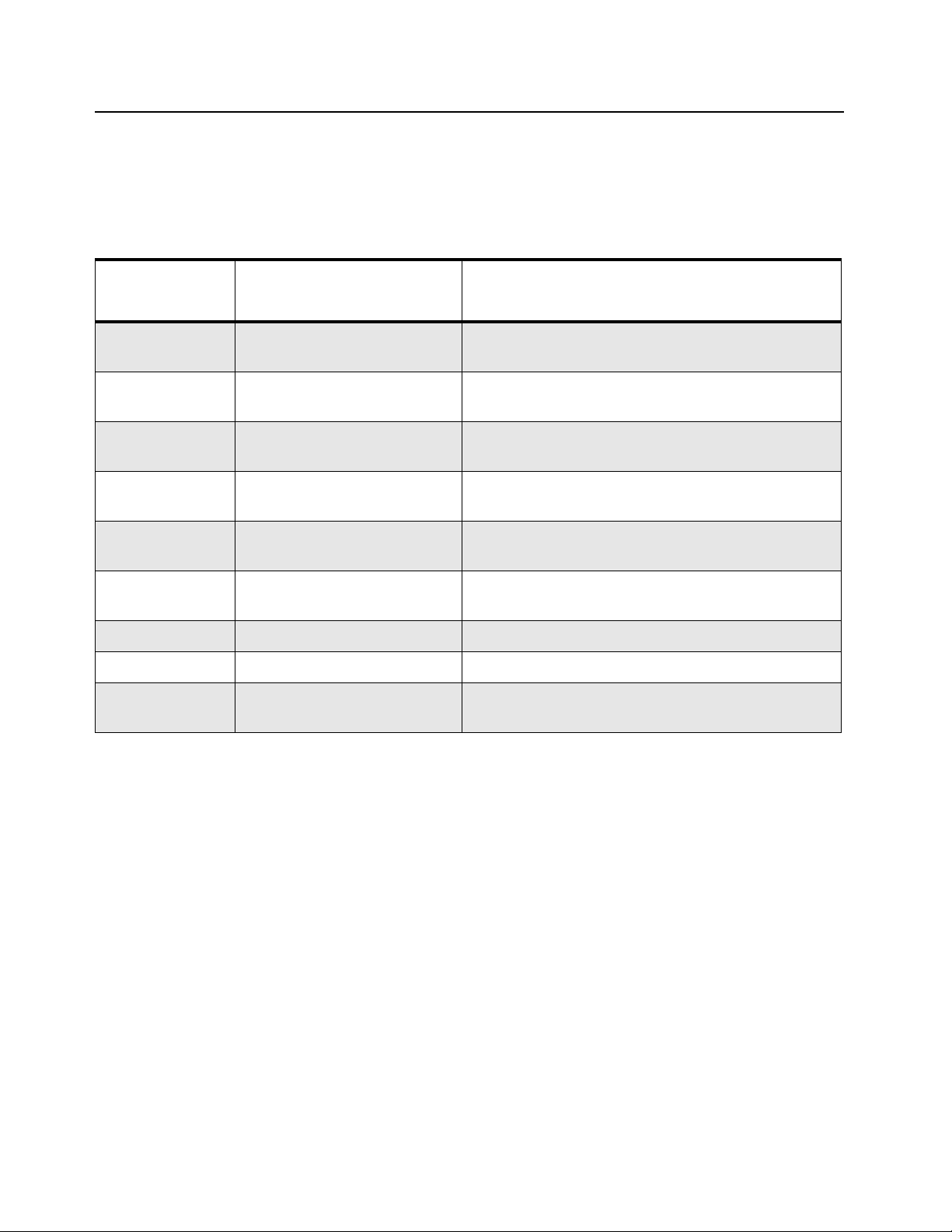
2.2 Service Aids
Table 2-2 lists the service aids recommended for working on the radio. While all of these items are
available from Motorola, most are standard workshop equipment items, and any equivalent item
capable of the same performance may be substituted for the item listed.
Table 2-2. Service Aids
Motorola Part
No.
RLN4460_ Portable Test Set Enables connection to the audio/accessory jack.
GMVN5141_ Customer Programming
Software on DVD-ROM
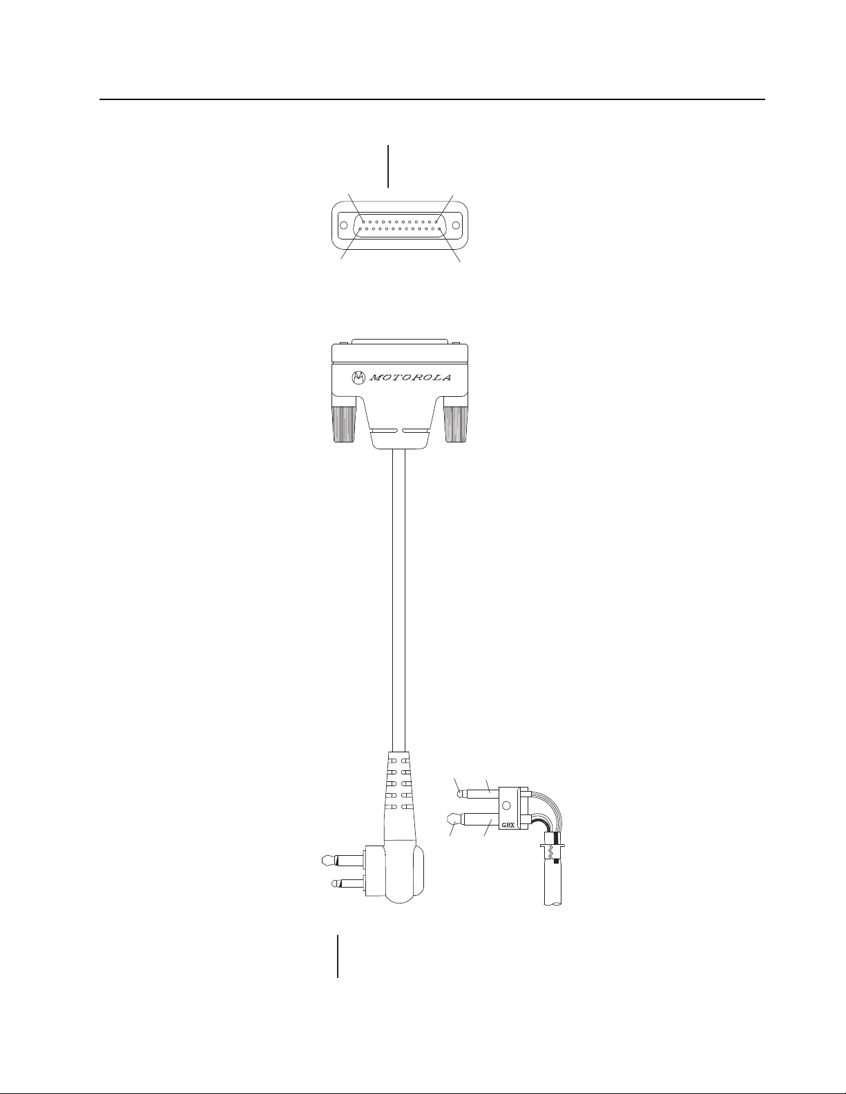
PMKN4128_ Portable Programming Cable This cable connects the radio to a USB port for radio
PMKN4156_ Portable Test Cable This cable connects the radio to RLN4460 Portable
0180305K08EPP 7.5V Universal Battery
Eliminator
5886564Z01 RF Adaptor Application adapts radio's antenna port to BC
1185937A01 Grease Acts to lubricate parts.
6686533Z01 Chassis and Knob Opener Separates the chassis from the front housing.
N/A Flat Square Tip Plastic
Tweezer
Description Application
Allows switching for radio testing.
Allows servicer to program radio parameters, tune
and troubleshoot radios.
programming and data applications.
Test Set for test and measurement.
Connects to radio battery eliminator cable.
cabling of test equipment.
Remove components during disassembly.
“P2”
#1
#4
“P3”
“P1”
#1
#5
#2
#1
#3
#5
#4
Test Equipment and Service Aids: Portable Programming Cable 2-3
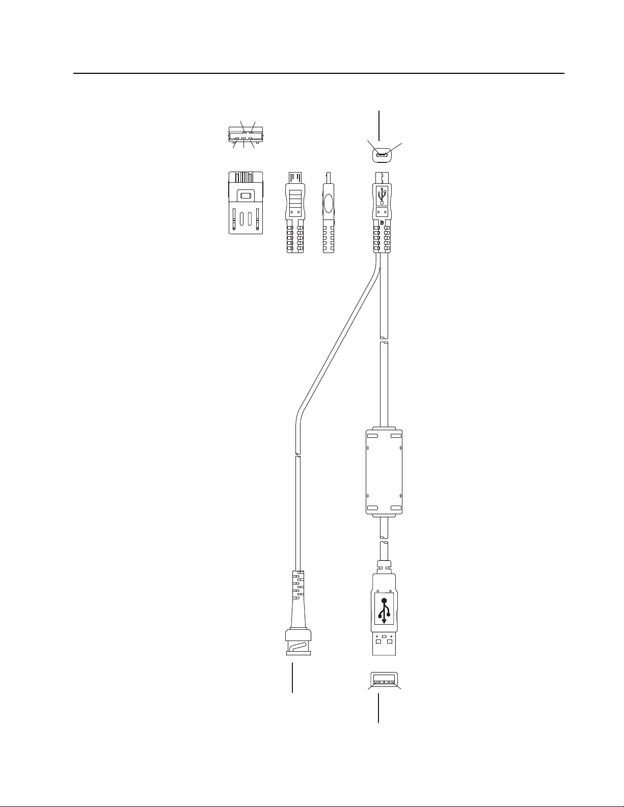
2.3 Portable Programming Cable
Figure 2-1. Portable Programming Cable with TTR (PMKN4128_)
2-4 Test Equipment and Service Aids: Portable Programming Cable
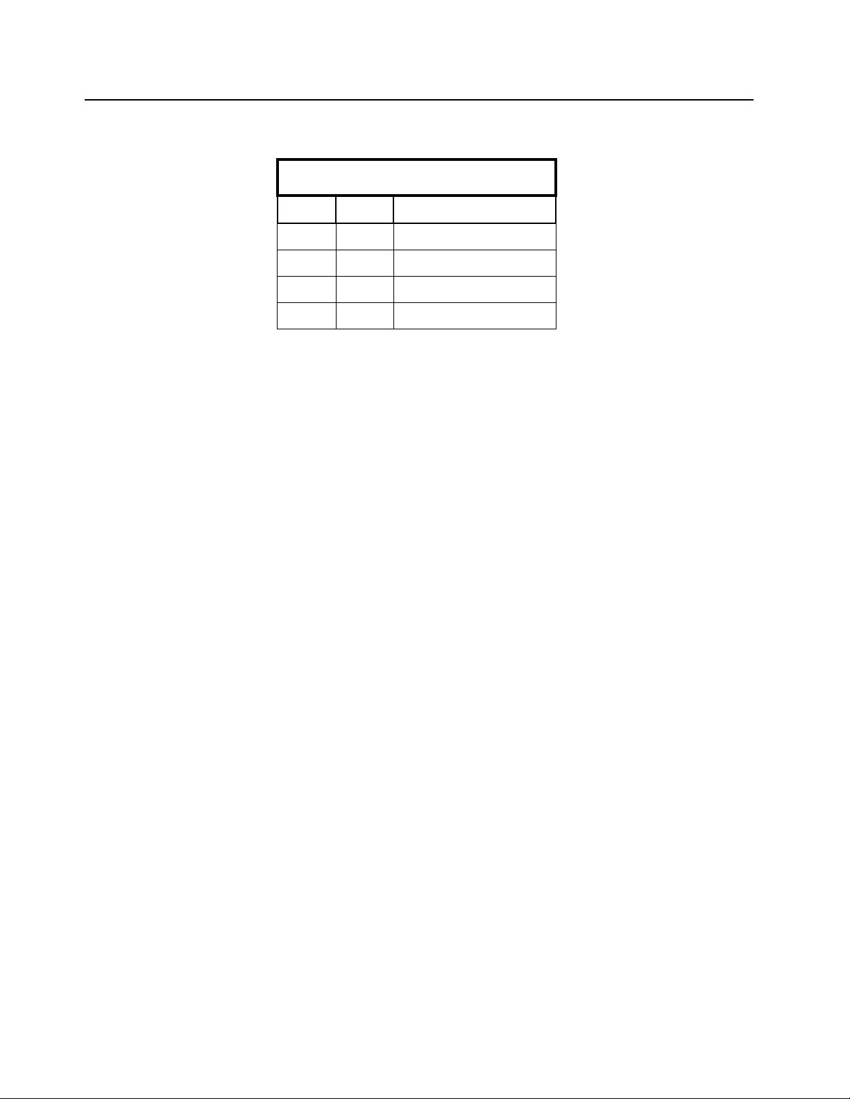
Table 2-3. Pin Configuration of Portable Programming Cable with TTR
CONNECTION
P1 P2 P3 Function
11 VCC(5V)
22
33
4
5
4 BNC Shell GROUND
DATA-
DATA+
BNC Center Pin TTR
#2
#1
#3
#4
“P1”
“P2”
#25
#13
#1
#14
Test Equipment and Service Aids: Portable Test Cable 2-5
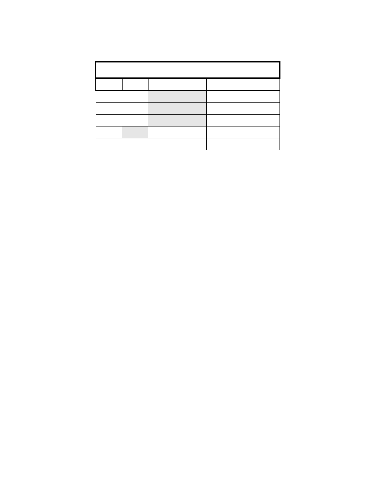
2.4 Portable Test Cable
Figure 2-2. Portable Test Cable (PMKN4156_ )
2-6 Test Equipment and Service Aids: Portable Test Cable
Table 2-4. Pin Configuration of Portable Test Cable
CONNECTION
P1 P2 Function
1 1,5 GROUND
2 7,24 EXTERNAL MIC
3 16 EXTERNAL SPEAKER -
4
17 EXTERNAL SPEKAER +
Chapter 3 Transceiver Performance Testing
3.1 General
These radios meet published specifications through their manufacturing process by utilizing highaccuracy laboratory-quality test equipment. The recommended field service equipment approaches
the accuracy of the manufacturing equipment with few exceptions. This accuracy must be
maintained in compliance with the manufacturer’s recommended calibration schedule.
Although these radios function in digital and analog modes, all testing is done in analog mode.
3.2 Setup
Supply voltage is provided using a 7.5 VDC power supply. The equipment required for alignment
procedures is connected as shown in the Radio Tuning Equipment Setup Diagram, Figure 4-2.
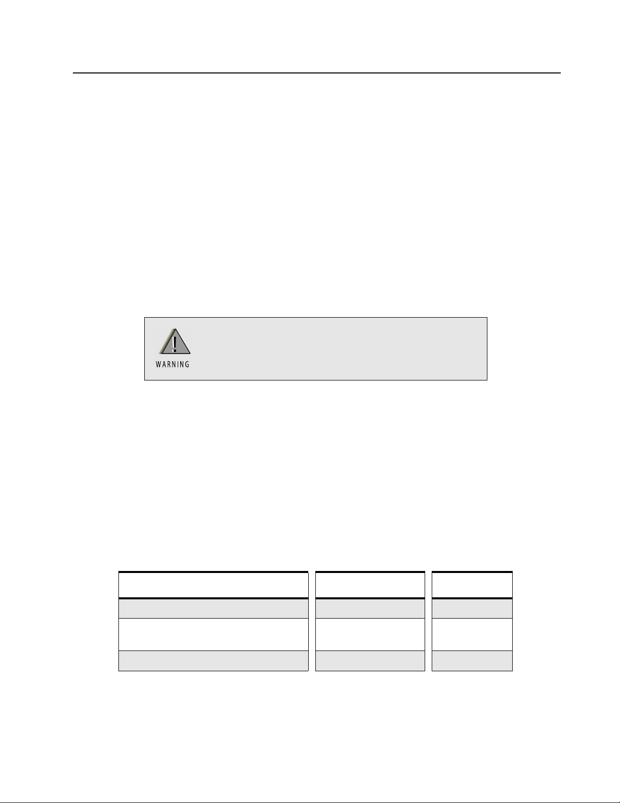
Do NOT use any form of connector, e.g. wires, crocodile
clips, and probes, to supply voltage to the radio, other
than the Motorola approved battery eliminator.
Initial equipment control settings should be as indicated in Table 3-1. The remaining tables in this
chapter contain the following related technical data:
Tabl e Number Title
3-2 Test Environments
3-3 Test Frequencies
3-4 Transmitter Performance Checks
3-5 Receiver Performance Checks
Table 3-1. Initial Equipment Control Settings
Service Monitor Power Supply Test Set
Monitor Mode: Power Monitor Voltage: 7.5Vdc Speaker set: A
RF Attn: -70 DC on/standby:
Standby
AM, CW, FM: FM Volt Range: 10V PTT: OFF
Speaker/load:
Speaker
 Loading...