

Page 1

QM-Height
High-Precision Digital
Height Gauge
QMH-600A
QMH-600B
QMH-350A
QMH-350B
QMH-24"A
QMH-24"B
QMH-14"A
QMH-14"B
User's Manual
- Instructions for use -
Read this User's Manual thoroughly before operating
the instrument. After reading, retain it close at hand for
future reference.
No. 99MAF029B2
Date of publication: February 1, 2017
Page 2

Applicable product names and model numbers
QMH-600A
z
518-232
QMH-600B
z
518-236
QMH-350A
z
518-230
QMH-350B
z
518-234
QMH-24"A
z
518-233
QMH-24"B
z
518-237
QMH-14"A
z
518-231
QMH-14"B
z
518-235
Notice Regarding This Guide
yMitutoyo Corporation assumes no responsibilities for any damage to the instrument, caused by its
use not conforming to the procedure described in this User's Manual.
yUpon loan or transfer of this instrument, be sure to attach this User's Manual to the instrument.
yIn the event of loss or damage to this manual, immediately contact a Mitutoyo sales office or your
dealer.
yBefore operation of the instrument, thoroughly read this manual to comprehend its contents.
yParticularly, for full understanding of information, carefully read "Safety Precautions" and
"Precautions for Use" at the outset of this manual before using the instrument.
yThe contents in this manual are based on the information current as of February, 2017.
yNo part or whole of this manual may be transmitted or reproduced by any means without prior
written permission of Mitutoyo Corporation.
ySome screen displays in this manual may be highlighted, simplified or partially omitted for
convenience of explanation. In addition, some of them may differ from actual ones to the extent that
no user will misunderstand the functions and operations.
yThe corporation, organization and product names that appear in this manual are their trademarks
or registered trademarks.
© 2017 Mitutoyo Corporation. All rights reserved.
No. 99MAF029B
Page 3
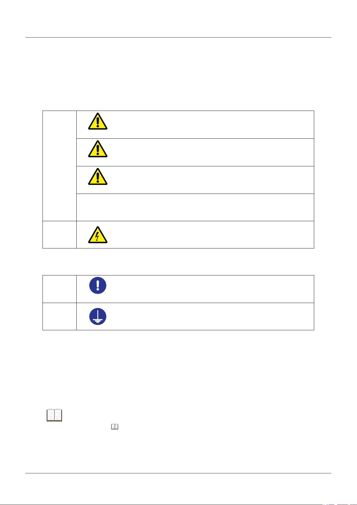
CONVENTIONS USED IN THIS MANUAL
Conventions used in this User's Manual are roughly divided into two types (safety reminders and
mandatory actions). Moreover, these safety symbols include general warnings and specific warnings.
Specific warning symbols are provided with concrete pictograms inside of them.
Safety reminder conventions and wording warning against potential hazards
Indicates an immediately hazardous situation which, if not avoided, will result
in serious injury or death.
Indicates a potentially hazardous situation which, if not avoided, could result in
serious injury or death.
Indicates a potentially hazardous situation which, if not avoided, may result in
minor injury.
General
DANGER
WARNING
CAUTION
NOTE
Specific
Conventions and wording indicating mandatory actions
General
Mandator y
Specific
Conventions and wording indicating referential information or referential
Indicates a potentially hazardous situation which, if not avoided, may result in
property damage.
Alerts the user to a specific hazardous situation that means "Caution, risk of
electric shock".
Indicates concrete information about mandatory actions.
Indicates that grounding needs to be implemented.
locations
Tips
Indicates referential information such as that for when the operating methods and procedures which
are printed in these sentences are to be applied to specific conditions.
Indicates referential locations if there is information that should be referred to in this guide or an
extraneous manual.
E.g.: For details,
"2.1 Measuring the Height" (page 17)
i
No. 99MAF029B
Page 4
Safety Precautions
Read these Safety Precautions thoroughly before operating the system to use it properly.
These safety precautions include such information as to prevent an injury to the operator and other
persons or damage to property. Be sure to observe the precautions.
• Do not disassemble or modify this product. Doing so can result in fire or electric shock.
• Do not place the product on an unstable surface. It may fall or topple over, causing an injury.
WARNING
CAUTION
• Do not place containers with water, such as flower pots, near this product. If water gets into the
device, a fire or electric shock may occur. If water does get into the device, turn off the power, and
contact us. Continuing to use the device may result in a fire or electric shock.
• Do not use the device in areas where volatile gases may be released. Doing so can result in a fire.
• Do not apply an external voltage to the product with a device such as an electric engraver. Doing so
may lead to damage or malfunction.
• If the device will not be used for an extended period of time, remove the batteries. Battery leakage
can damage the device.
• Only use LR6 (AA alkaline) or Ni-MH (nickel metal hydride) batteries. Handle the batteries
according to their instructions.
• Do not charge or disassemble the accompanying batteries. They may short circuit.
ii
No. 99MAF029B
Page 5

Precautions for Use
Product applications and handling
This product is a measuring instrument.
z
Do not use it for any purposes other than measuring.
This product is precision equipment.
z
It must be carefully handled. Be careful not to apply excessive shock or force to any of the parts during
operation.
Installation environment
Only use this product in the following environments.
yAreas free of dirt and dust
yAreas free of vibrations
yAreas with an ambient temperature between 0 C and 40 C (For precision measurements, the
temperature should be consistently around 20 C.)
yAreas with low humidity
yOn a surface plate
Avoid using the product in the following environments.
yIn locations where it may directly exposed to cutting fluids, water, etc.
yIn locations where it may be exposed directly to sunlight or hot or cold wind
yIn locations near machines that generate electromagnetic noise, such as welders or electrical
discharge machines
Maintenance
yClean the main unit, base, or probe by wiping it with a lint-free cloth or paper towel dampened with
a neutral detergent. Do not use an organic solvent such as a thinner.
yIn order to prevent dirt and dust accumulation, we recommend covering the main unit with the
included product cover.
Power Supply
yTurn off the power after use.
yDo not connect the AC adapter (optional accessory) to a high-current power supply used by
machine tools or large CNC measuring instrument.
iii
No. 99MAF029B
Page 6

Electromagnetic Compatibility (EMC)
This product complies with the EMC Directive. Note that, in environments where electromagnetic
interference exceeds the EMC requirements defined in this directive, appropriate countermeasures are
required to ensure product performance.
This is an industrial product. Not intended for use in a residential environment. Use of this product in a
residential environment may cause an electromagnetic interference with other instruments. In such a
case, appropriate measures against electromagnetic interference are required.
Export Control Compliance
This product falls into the Catch-All-Controlled Goods and/or Catch-All-Controlled Technologies
(including Programs) under Category 16 of Appended Table 1 of the Export Trade Control Order or
under Category 16 of the Appended Table of Foreign Exchange Control Order, based on the Foreign
Exchange and Foreign Trade Act of Japan.
If you intend re-export of the product from a country other than Japan, re-sale of the product in a
country other than Japan, or re-provision of the technology (including program), you are obligated to
observe the regulations of your country.
Also, if an option is added or modified to add a function to this product, this product may fall under the
category of List-Control Goods and/or List-Control Technology (including Programs) under Category 1
- 15 of Appended Table 1 of the Export Trade Control Order or under Category 1 - 15 of the Appended
Table of Foreign Exchange Control Order, based on Foreign Exchange and Foreign Trade Act of
Japan. In that case, if you intend re-export of the product from a country other than Japan, re-sale of
the product in a country other than Japan, or re-provision of the technology (including program), you
are obligated to observe the regulations of your country. Please contact Mitutoyo in advance.
Notes on Export to EU Member Countries
When you intend export of this product to any of the EU member countries, you may be required
to provide User's Manual(s) in English and EU Declaration of Conformity in English (under certain
circumstances, User's Manual(s) in the destination country's official language and EU Declaration
of Conformity in the destination country's official language). For detailed information, please contact
Mitutoyo in advance.
Disposal of Old Electrical & Electronic Equipment (Applicable in the European Union and other European countries with separate collection systems)
This symbol on the product or on its packaging is based on the WEEE Directive (Directive on
Waste Electrical and Electronic Equipment), which is a regulation in EU member countries, and
indicates that this product shall not be treated as household waste.
To reduce environmental impact and minimize the volume of landfill, please cooperate in reuse
and recycling.
For information on how to dispose of the product, please contact your dealer or the nearest
Mitutoyo sales office.
iv
No. 99MAF029B
Page 7
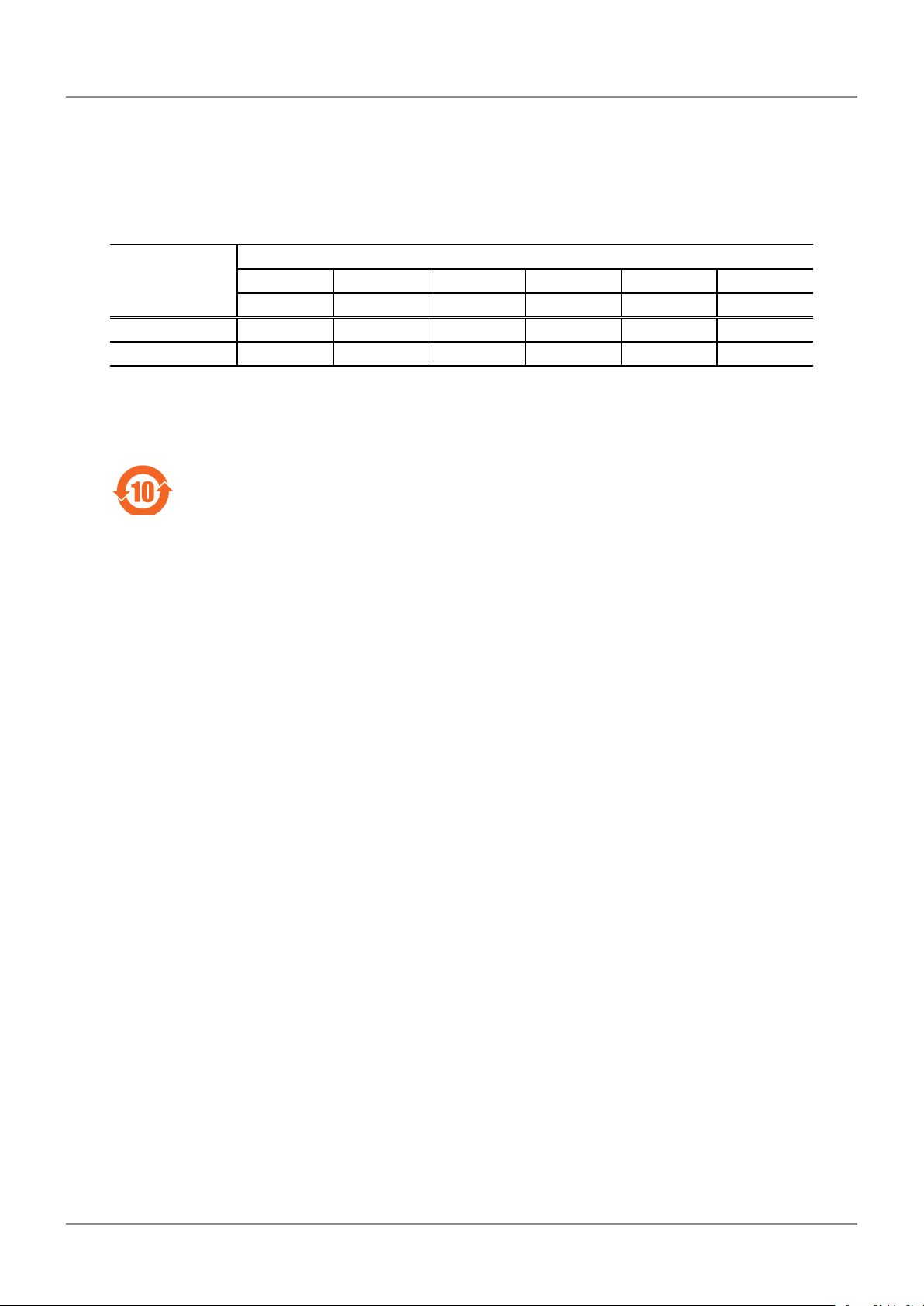
China RoHS Compliance Information
This product meets China RoHS requirements. See the table below.
产品中有害物质的名称及含量
有害物质
部件名称
本体 × ○ ○ ○ ○ ○
配件 ○ ○ ○ ○ ○ ○
本表格依据 SJ/T 11364 的规定编制。
○ :表示该有害物质在该部件所有均质材料中的含量均在 GB/T 26572 规定的限量要求以下。
× :表示该有害物质至少在该部件的某一均质材料中的含量超出 GB/T 26572 规定的限量要求。
环保使用期限标识,是根据电器电子产品有害物质限制使用管理办法以及,电子电气产品有害物
质限制使用标识要求 (SJ/T11364-2014),制定的适用于中国境内销售电子电气产品的标识。
电子电气产品只要按照安全及使用说明内容,正常使用情况下,从生产月期算起,在此期限内,
产品中含有的有毒有害物质不致发生外泄或突变,不致对环境造成严重污染或对其人身、财产造
成严重损害。
产品正常使用后,要废弃在环保使用年限内或者刚到年限的产品时,请根据国家标准采取适当的
方法进行处置。
另外,此期限不同于质量 / 功能的保证期限。
铅 汞 镉 六价铬 多溴联苯 多溴二苯醚
(Pb) (Hg) (Cd) (Cr(VI)) (PBB) (PBDE)
v
No. 99MAF029B
Page 8

Warranty
In the event that this product should prove defective in workmanship or material, within one year from
the date of original purchase for use, it will be repaired or replaced free of charge. Please contact your
dealer or the nearest Mitutoyo sales office.
If this product fails or is damaged for any of the following reasons, it will be subject to a repair charge
even if it is still under warranty.
yFailure or damage owing to fair wear and tear.
yFailure or damage owing to inappropriate handling, maintenance, or repair, or to unauthorized
modification.
yFailure or damage owing to transport, dropping, or relocation of the product after purchase.
yFailure or damage owing to fire, salt, gas, abnormal voltage, lightning surge, or natural disaster.
yFailure or damage owing to use in combination with hardware or software other than that
designated or permitted by Mitutoyo.
yFailure or damage owing to use in ultra-hazardous activities.
This warranty is effective only where the instrument is properly installed and operated in conformance
with the instructions in this manual within the original country of the installation.
EXCEPT AS SPECIFIED IN THIS WARRANTY, ALL EXPRESS OR IMPLIED CONDITIONS,
REPRESENTATIONS, AND WARRANTIES OF ANY NATURE WHATSOEVER INCLUDING,
WITHOUT LIMITATION, ANY IMPLIED WARRANTY OF MERCHANTABILITY, FITNESS FOR A
PARTICULAR PURPOSE, NONINFRINGEMENT OR WARRANTY ARISING FROM A COURSE OF
DEALING, USAGE, OR TRADE PRACTICE, ARE HEREBY EXCLUDED TO THE MAXIMUM EXTENT
ALLOWED BY APPLICABLE LAW.
You assume all responsibility for all results arising out of the selection of this product to achieve its
intended results.
Disclaimer
IN NO EVENT WILL MITUTOYO, ITS AFFILIATED AND RELATED COMPANIES AND SUPPLIERS
BE LIABLE FOR ANY LOST REVENUE, PROFIT, OR DATA, OR FOR SPECIAL, DIRECT,
INDIRECT, CONSEQUENTIAL, INCIDENTAL, OR PUNITIVE DAMAGES HOWEVER CAUSED AND
REGARDLESS OF THE THEORY OF LIABILITY ARISING OUT OF THE USE OF OR INABILITY TO
USE THIS PRODUCT EVEN IF MITUTOYO OR ITS AFFILIATED AND RELATED COMPANIES AND/
OR SUPPLIERS HAVE BEEN ADVISED OF THE POSSIBILITY OF SUCH DAMAGES.
If, notwithstanding the foregoing, Mitutoyo is found to be liable to you for any damage or loss which
arises out of or is in any way connected with use of this product by you, in no event shall Mitutoyo's
and/or its affiliated and related companies' and suppliers' liability to you, whether in contract, tort
(including negligence), or otherwise, exceed the price paid by you for the product only.
BECAUSE SOME COUNTRIES, STATES OR JURISDICTIONS DO NOT ALLOW THE EXCLUSION
OR THE LIMITATION OF LIABILITY FOR CONSEQUENTIAL OR INCIDENTAL DAMAGES, IN SUCH
COUNTRIES, STATES OR JURISDICTIONS, MITUTOYO'S LIABILITY SHALL BE LIMITED TO THE
EXTENT PERMITTED BY LAW.
vi
No. 99MAF029B
Page 9
About This Document
Positioning of This Document in Document Map
This document explains how to use the product and provides troubleshooting information.
In addition to this document, a setup guide and a quick reference chart are available.
Operation
z
User's Manual (This Document)
Setup
z
Setup Manual
Quick reference chart
z
Quick Reference Manual
Intended Readers and Purpose of This Document
Intended Readers
z
This document is intended for beginners of the High-Precision Digital Height Gauge.
The readers are assumed to have been familiar with basic operations of a PC and Windows.
They are also assumed to be able to understand individual instructions by reading screen displays.
Purpose
z
To use this product safely and correctly, read this document thoroughly. After reading, keep it in a safe
place close to the product.
This document is aimed at understanding how to use the High-Precision Digital Height Gauge to
perform basic measurements and specific usage applications.
vii
No. 99MAF029B
Page 10

Contents
CONVENTIONS USED IN THIS MANUAL ………………………………………………… i
Safety Precautions …………………………………………………………………………… ii
Precautions for Use …………………………………………………………………………… iii
Electromagnetic Compatibility (EMC) …………………………………………………… iv
Export Control Compliance ………………………………………………………………… iv
Notes on Export to EU Member Countries ……………………………………………… iv
Disposal of Old Electrical & Electronic Equipment (Applicable in the European
Union and other European countries with separate collection systems) ………… iv
China RoHS Compliance Information ……………………………………………………… v
Warranty ………………………………………………………………………………………… vi
Disclaimer ……………………………………………………………………………………… vi
About This Document …………………………………………………………………………vii
1 Before Using This Product …………………………………………………………… 1
1.1 Product Capabilities ………………………………………………………………… 1
1.2 Part Names and Functions ………………………………………………………… 2
1.2.1 Main Unit……………………………………………………………………………………… 2
1.2.2 Display Unit ………………………………………………………………………………… 4
1.3 Basic Operations …………………………………………………………………… 7
1.3.1 Turning On the Power ……………………………………………………………………… 7
1.3.2 Moving the Probe …………………………………………………………………………… 7
1.3.3 Moving the Main Unit ……………………………………………………………………… 8
1.4 Preparing Measurements …………………………………………………………10
1.4.1 Origin Setup …………………………………………………………………………………10
1.4.2 Setting the Probe Diameter …………………………………………………………………14
2 Basic Measuring Methods ………………………………………………………………17
2.1 Measuring the Height ………………………………………………………………17
2.2 Measuring the Width ………………………………………………………………19
2.3 Measuring the Inner Diameter ……………………………………………………21
2.4 Measuring the Outer Diameter ……………………………………………………25
2.5 Measuring the Plane Displacement (Plane Scanning Measurement) …………29
3 Specific Usage Applications ……………………………………………………………31
3.1 Calculating the Difference Between 2 Measurements …………………………31
3.1.1 Determining the Difference Between the Most Recently Measured Value ……………32
viii
No. 99MAF029B
Page 11

3.1.2
3.1.3 Calculating the Difference Between Values Stored in the Memory ……………………35
Continuously Measuring the Distance from One Specific Point to Multiple Other Points
…33
3.2 Judging the Tolerance ………………………………………………………………38
3.2.1 Setting the Upper and Lower Limits ………………………………………………………38
3.2.2 Enabling/Disabling the Judgment Function ………………………………………………39
3.3 Simplifying Measurement Procedures ……………………………………………40
3.3.1 Registering a Measurement Procedure ……………………………………………………40
3.3.2 Measuring Using a Registered Measurement Procedure ………………………………42
3.4 Setting the Terminating Method for Scanning Measurements …………………43
3.5 Holding the Displayed Measurement Results ……………………………………44
3.6 Setting the Resolution for Measurements ………………………………………44
3.7 Setting the Time Until the Power Turns Off (Auto-Off) …………………………45
3.8 Setting the LED Lighting Time ……………………………………………………46
3.9 Outputting Measurement Results to an External Device ………………………47
3.9.1 Outputting to a Mini Printer (Optional Accessory) ………………………………………47
3.9.2 Outputting to a PC (Windows Only) ………………………………………………………48
4 Troubleshooting …………………………………………………………………………51
4.1 If the Following Problem Occurs …………………………………………………51
4.2 If Error Messages Are Displayed …………………………………………………53
5 Specifications ……………………………………………………………………………55
5.1 Basic Specifications …………………………………………………………………55
5.2 Digimatic Data Output Specification ………………………………………………57
5.2.1 Data Format …………………………………………………………………………………57
5.2.2 Connector Specification ……………………………………………………………………57
5.2.3 Timing Chart …………………………………………………………………………………58
5.3 USB Data Output Specification ……………………………………………………59
5.3.1 Communication Specification ……………………………………………………………… 59
5.3.2 Data Format …………………………………………………………………………………59
5.3.3 Connector Specification ……………………………………………………………………59
5.3.4 Data Format Examples………………………………………………………………………59
5.4 Accessories …………………………………………………………………………60
5.5 Optional Accessories ………………………………………………………………61
SERVICE NETWORK
Revision History
ix
No. 99MAF029B
Page 12

x
No. 99MAF029B
Page 13

1 Before Using This Product
1
This chapter explains the product's characteristics, part names and functions, basic operations, and
the settings that must be configured prior to measurement.
1.1
This product is a measuring instrument that makes measurements by vertically moving a part called
a probe into contact with a specific point, and calculating the height of that point. Because the
measurements are obtained from the probe's position, this product can measure the inner diameter of
holes and the outer diameter of cylinders as well.
Before Using This Product
Product Capabilities
(2)
(1)
Measurement
point
Bring the probe into contact with the point you want to measure (1), and read the displayed measurement (2).
1
No. 99MAF029B
Page 14
1 Before Using This Product
1.2
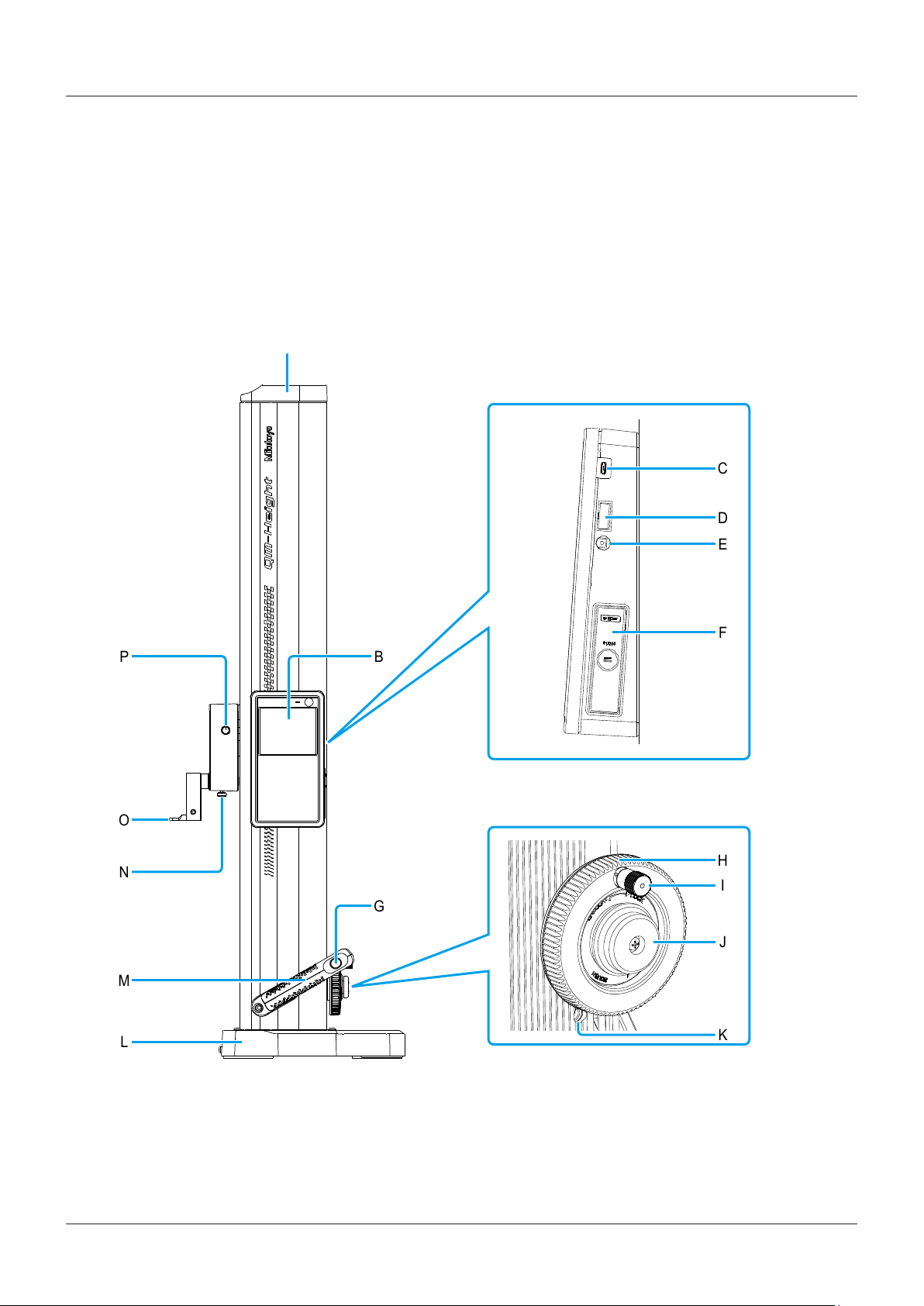
Part Names and Functions
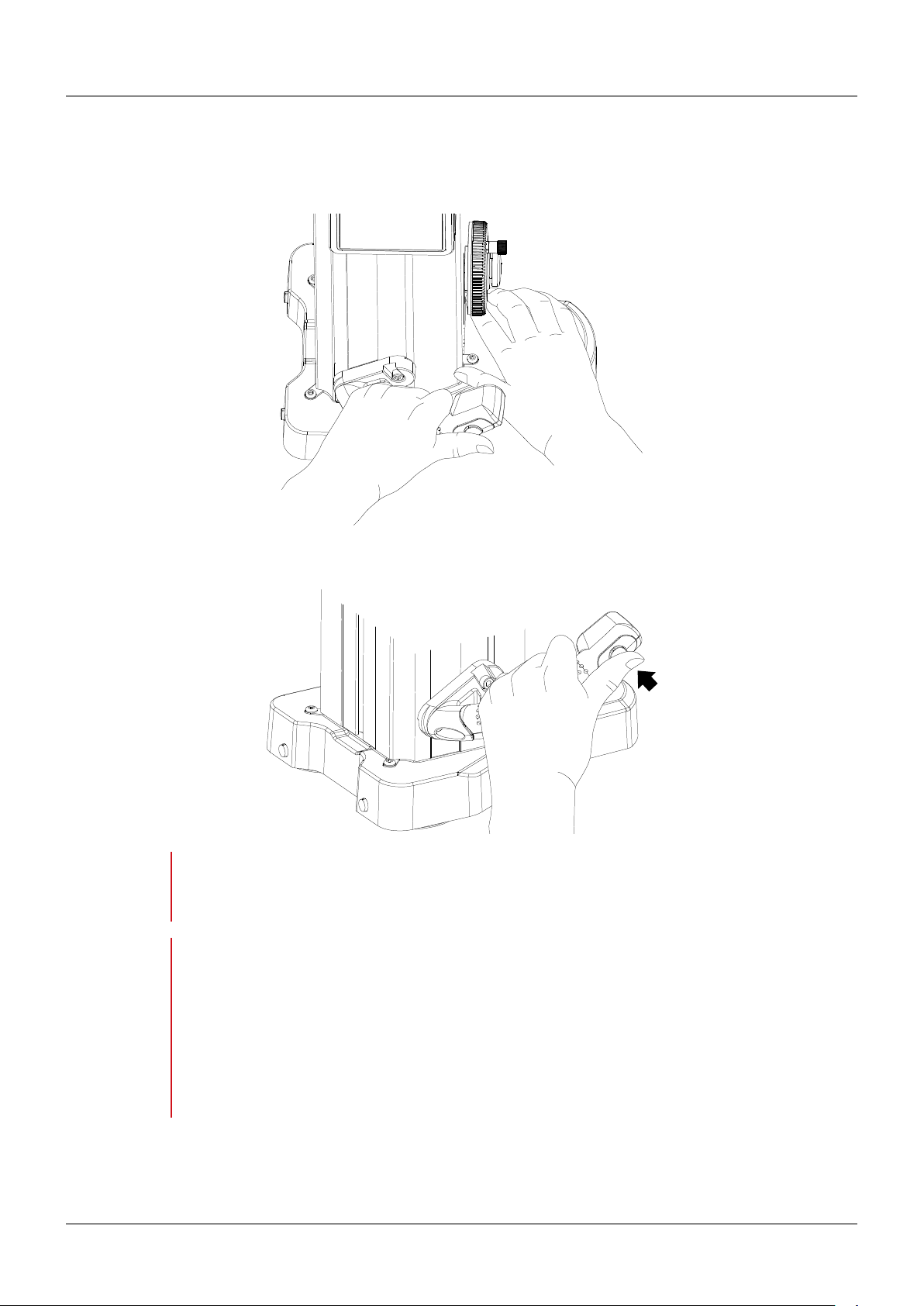
1.2.1 Main Unit
A
C
D
E
P B
O
N
M
L
F
H
I
G
J
K
2
No. 99MAF029B
Page 15

1 Before Using This Product
A Head cover B Display unit
C Micro USB connector (AB receptacle)
D Digimatic output connector*1
*1
This port is for connecting your PC with a
micro USB cable.
E DC jack
F Battery case
*1
This jack is for connecting the optional AC
adapter.
Displays measurements and any messages.
This port is for connecting the optional
Digimatic mini-processor (DP-1VR, etc.).
A case for inserting the batteries.
G Air-float switch (QMH-600B/QMH-350B/
QMH-24"B/QMH-14"B only)
This switch uses the air-float function to
make the main unit float.
NOTE
Measuring with the air-float function
active can cause measurement errors.
I Probe fine adjustment knob
Pulling the knob and turning it moves the
probe slowly.
K Float amount adjustment screw (QMH-600B/
QMH-350B/QMH-24"B/QMH-14"B only)
Adjusts the amount of airflow used in the
air-float function. Turning the screw right
increases airflow, and turning it left reduces
airflow.
M Carrier grip
Hold the carrier grip when moving the main
unit along the surface plate.
O Probe
Used for obtaining measurements. Touch
the sphere on the tip of the probe to the
workpiece to obtain the measurements.
H Probe up/down wheel
The probe moves up and down as the wheel
is turned left and right.
J Clamp screw
Fixes the rotational movement of the probe
up/down wheel.
L Base
Contact surface used when installing the
main unit on the surface plate. Grip the base
when moving the main unit along the surface
plate.
N Probe clamp knob
Clamps the probe so that it does not come
out.
P Clamp knob
Fixes the movement of the probe.
*1
During use, we recommend securing the cable with the included cable clamp.
3
No. 99MAF029B
Page 16
1 Before Using This Product
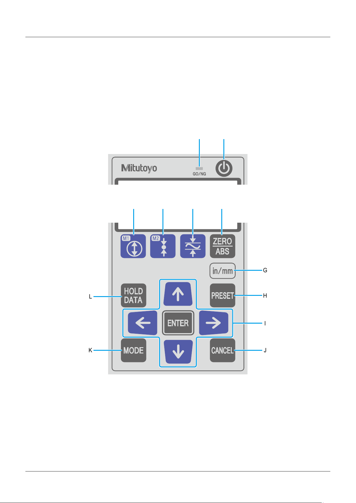
1.2.2 Display Unit
Operation panel
A
C D E F
L
B
G
H
I
K
4
J
No. 99MAF029B
Page 17

1 Before Using This Product
A Shows the result of the tolerance judgment.
Tips
C Measures the inner diameter.
Tips
E Measures the maximum, minimum, and
displacement values (maximum – minimum =
displacement) of a horizontal plane.
Tips
G Changes the setting for units between inches
and millimeters (only on models that support
inches).
For details, "3.2 Judging the
Tolerance" (page 38)
For details, "2.3 Measuring the
Inner Diameter" (page 21)
For details, "2.5 Measuring the
Plane Displacement (Plane Scanning
Measurement)" (page 29)
B Turns the power on or off.
D Measures the outer diameter.
Tips
F Changes the origin between ABS and INC
settings.
H Sets a value for the origin.
For details, "2.4 Measuring the
Outer Diameter" (page 25)
I
Changes numbers and settings. Press
to confirm an operation.
Tips
K Used to change settings for a specific
application, such as changing the
measurement resolution.
Tips
• Press and hold to reverse
the counting direction: Moving
the probe upwards decreases
the value, and moving the probe
downwards increases the value.
Press and hold the button again to
return to normal.
• If you reversed the counting
direction, follow the procedure in
"1.4.1 Origin Setup" (page
10) to reset the origin.
For details, "3 Specific Usage
Applications" (page 31)
J Cancels an operation.
L Holds a measurement in the display and
outputs the measurement results to external
devices.
Tips
For details, "3.5 Holding the
Displayed Measurement Results"
(page 44) and "3.9 Outputting
Measurement Results to an External
Device" (page 47)
5
No. 99MAF029B
Page 18
1 Before Using This Product
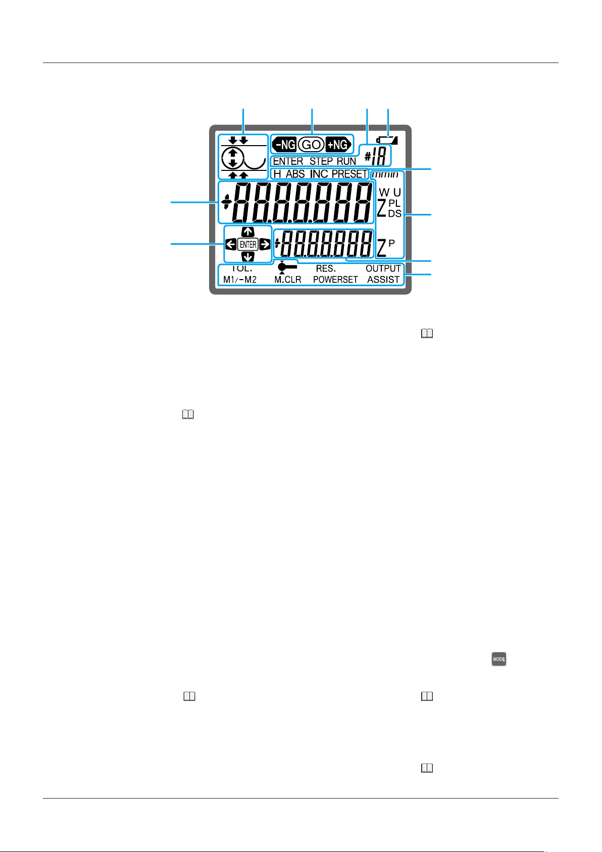
LCD screen
J
I
A B C D
E
F
G
H
A Displays an icon which represents an
operation.
C Displayed when registering measurement
steps or executing steps that have been
registered.
Tips
E Displayed during the following operations.
y[H]
When a measurement is being held in the
display.
y[ABS]/[INC]
When the origin has been changed
between ABS and INC settings.
y[PRESET]
When setting a value for the origin.
For details, "3.3 Simplifying
Measurement Procedures" (page 40)
B Shows the result of the tolerance judgment.
Tips
D Displayed when the battery is empty.
F The meanings of the following letters,
which are displayed during measuring, are
explained below.
y[ZP]
The difference between 2 measurements
y[U]/[L]
Upper/Lower tolerances
y[ZD]
Diameter
y[ZL]/[ZS]/[W]
Maximum/Minimum/Displacement
y[mm]
Millimeters (unit)
y[in]
Inches (unit)
For details, "3.2 Judging the
Tolerance" (page 38)
G Displays the difference with the previous
measurement.
Tips
I Shows which keys can be used during an
operation.
For details, "3.1 Calculating the
Difference Between 2 Measurements"
(page 31)
H Displays the available settings when is
pressed.
Tips
J Displays the measurement.
Tips
For details, "3 Specific Usage
Applications" (page 31)
For details, "2 Basic Measuring
Methods" (page 17)
6
No. 99MAF029B
Page 19
1 Before Using This Product
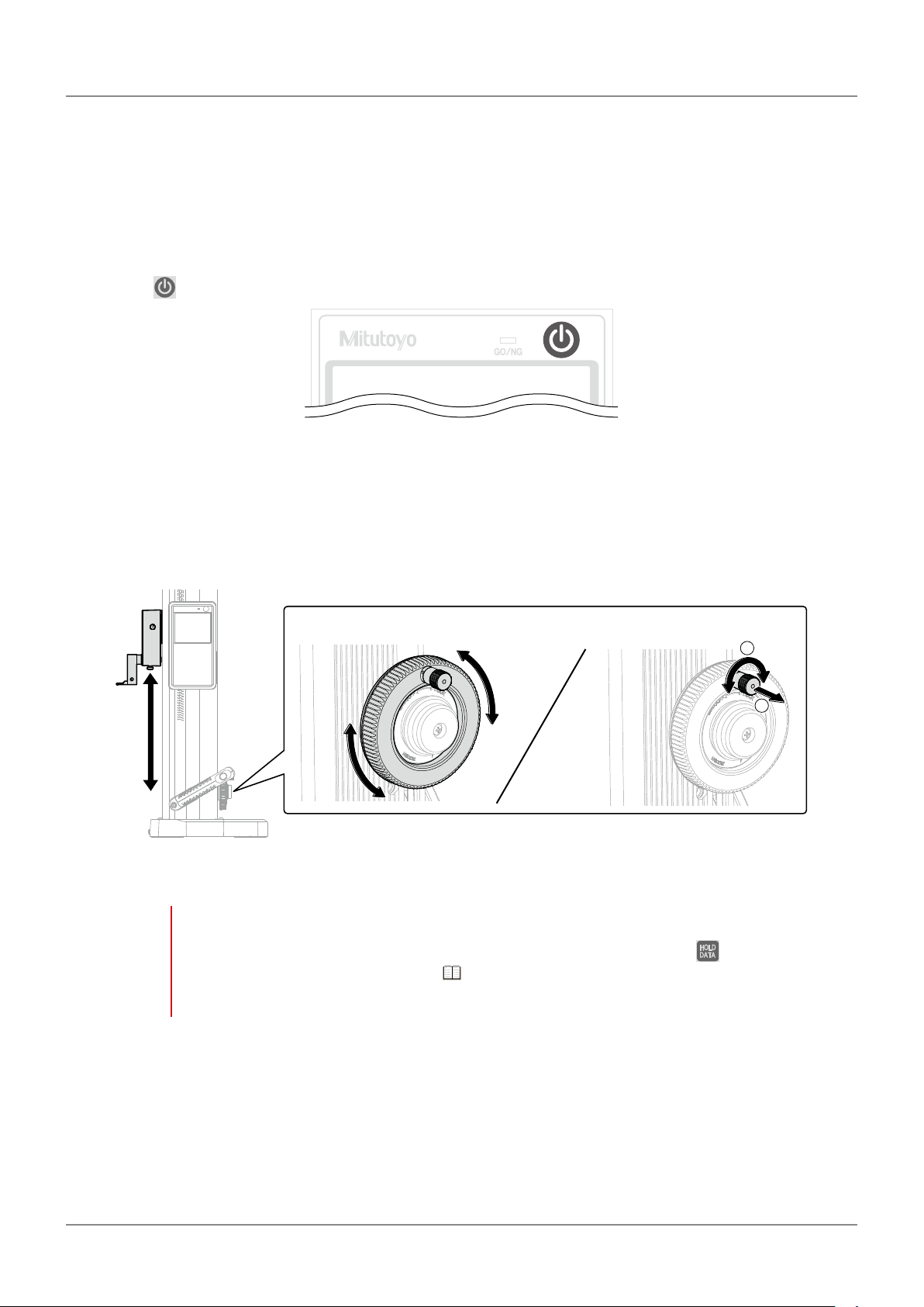
1.3
This section explains how to turn on the power, as well as how to move the probe and the main unit.
Basic Operations
1.3.1 Turning On the Power
Press on the upper right of the LCD screen to turn on the power.
1.3.2 Moving the Probe
Turn the probe up/down wheel right and left to move the probe up and down, respectively. When
bringing the probe into contact with the workpiece or surface plate, be sure to move the probe slowly.
The probe can be moved slowly by pulling out and turning the probe fine adjustment knob.
"Quick Movement (Coarse adjustment)" "Slow Movement (Fine adjustment)"
2
1
When the probe contacts the measurement surface with a consistent force, a beep sound is made, and
the height position is measured.
NOTE
• In order to prevent a reduction in the product's performance, do not move the probe by grabbing it.
• If the display value remains held even when you move the probe vertically, press
not release the hold, follow the steps in "When the displayed value is held, and the workpiece
cannot be measured" (page 52) to release the hold.
. If this does
7
No. 99MAF029B
Page 20
1 Before Using This Product
1.3.3 Moving the Main Unit
When moving the main unit on the surface plate, grab the base with your right hand and the carrier
grip with your left hand.
For QMH-600B/QMH-350B/QMH-24"B/QMH-14"B, pressing the air-float switch on the tip of the carrier
grip causes air to make the main unit float, allowing you to move it smoothly above the surface plate.
NOTE
NOTE
Do not move the product by grabbing parts other than the base or carrier grip. Doing so can negatively
affect measurement accuracy and the product itself.
If using the air-float function:
• Measuring with the air-float function active can cause measurement errors.
• Clean the surface plate in advance.
• Use a surface plate of Class JIS1 or higher. If the surface plate is scratched or uneven, the specified
performance may not be achieved.
• Use a rigid surface plate. If the surface plate warps under the weight of the product, the product
may not float.
8
No. 99MAF029B
Page 21
1 Before Using This Product
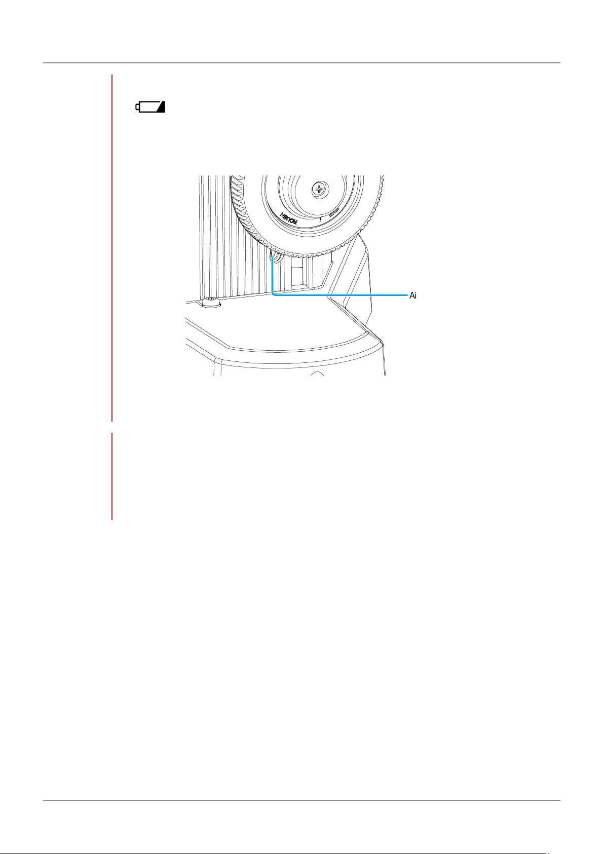
NOTE
If air-float does not work:
• If
with new ones.
• Use a flathead screwdriver to turn the air-float adjustment screw, and adjust the airflow. Turning the
screw right increases airflow, and turning it left reduces airflow. Adjust the amount relative to the
installation location.
is shown on the LCD screen, the air-float function cannot be used. Replace the batteries
Air-float
adjustment screw
NOTE
The airflow has been adjusted to provide optimal performance before shipment. We recommend
using the default settings as much as possible.
When adjusting the air-float flow:
• Due to the characteristics of the air-float mechanism, variations in airflow may cause the main unit
to vibrate. In this case, reduce the airflow.
• If you adjust the airflow, make sure that the friction between the surface plate and the main unit is
reduced before use.
9
No. 99MAF029B
Page 22
1 Before Using This Product
1.4
Complete the following setup before measuring.
yOrigin setup
yProbe diameter setup
Preparing Measurements
1.4.1 Origin Setup
Set the origin to use when measuring height. The dimensions measured from this origin will become
the height measurements. This product is compatible with both ABS and INC origins. Use one or the
other based on the application.
yABS origin
This method uses a user-defined value as the origin. When measuring the height from the surface
plate, set the surface plate as the origin point with a value of 0 mm.
Example: The surface plate is set as the origin at 0 mm.
Obtain the
measurement relative
to the surface plate
Surface plate
To use a datum other than the surface plate, assign that value as the origin point.
Example: Surface a1 is set as the origin at 50 mm.
Obtain the measurement relative to a1
Tips
a1
50 mm
For details about setting the ABS origin, "Setting the ABS origin" (page 11)
70 mm
10
No. 99MAF029B
Page 23
1 Before Using This Product
yINC origin
This method uses an arbitrary point on the workpiece as the origin. The specified point acts as the
datum for the measurements and is assigned a value of 0 mm.
Example: Surface a1 is set as the origin (normally 0 mm).
Obtain the measurement relative to a1
a1
Tips
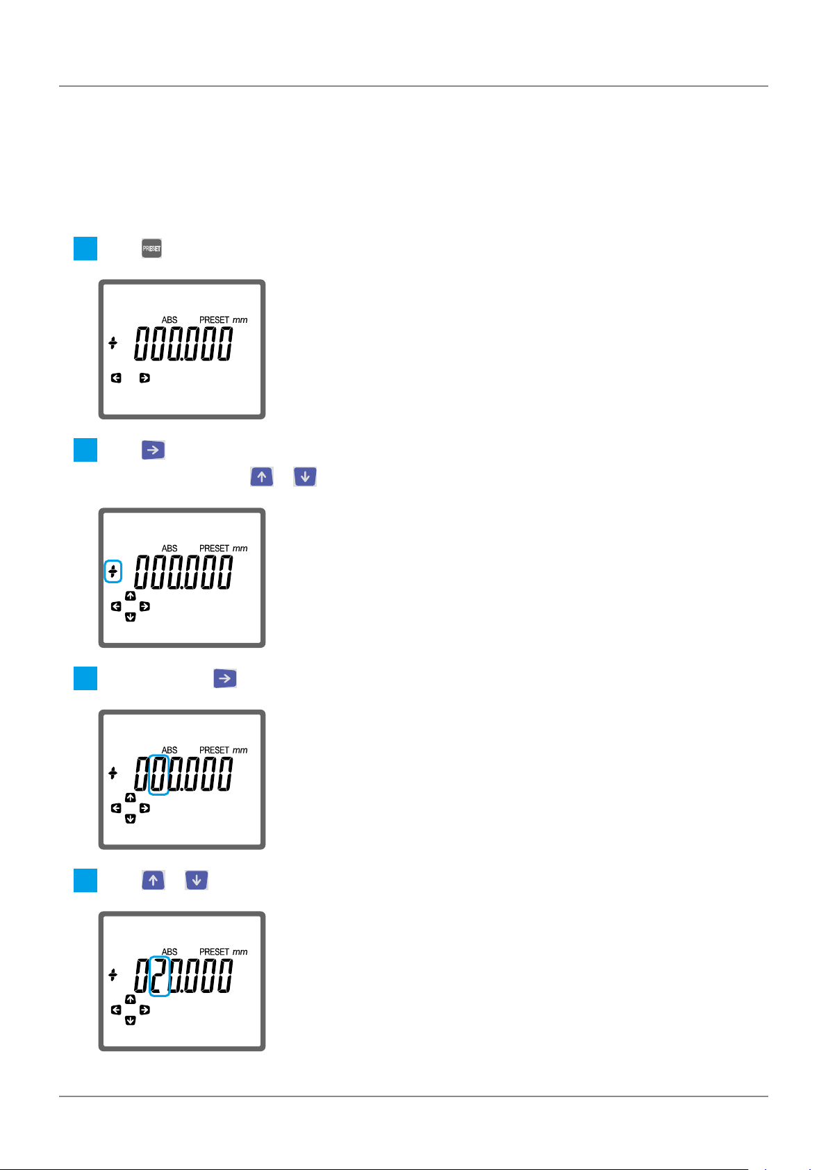
Setting the ABS origin
Setting the surface plate as the origin
z
Press .
1
Confirm that [+000.000] is displayed on the LCD screen.
2
If a different value is displayed, use , , , or to change the value to [+000.000].
For details about setting the INC origin, "Setting the INC origin" (page 13)
Tips
Slowly bring the probe into contact with the surface plate until a beep sound is made.
3
»The origin setup is complete.
For details about configuring the settings, "Setting a point other than the surface plate as the
origin" (page 12)
11
No. 99MAF029B
Page 24
1 Before Using This Product
Setting a point other than the surface plate as the origin
z
As an example, the procedure for setting the origin point to [+25.000 mm] using a 25 mm gauge block
is explained below.
Tips
Press .
1
Press to make [+] flash.
2
If [–] is displayed, press or to change it to [+].
You can perform the settings using the dial test indicator or the dial indicator instead of the probe.
Repeatedly press until the value in the 10s place flashes.
3
Press or to display [2].
4
12
No. 99MAF029B
Page 25
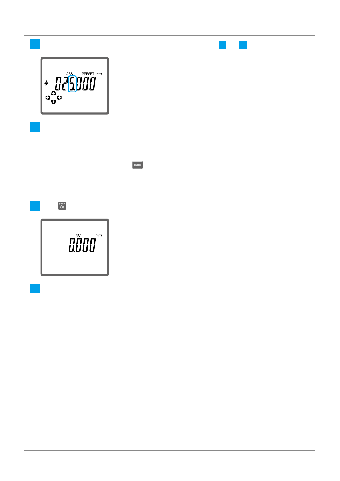
1 Before Using This Product
Display [5] in ones place using the same procedure described in steps
5
Slowly bring the probe into contact with the 25 mm gauge block until a beep sound is made.
6
»The origin setup is complete.
Tips
Setting the INC origin
Press .
1
For measurements using a dial test indicator or dial indicator, bring the stylus into contact with the
gauge block, and then press to finish the setup.
3
and 4.
Slowly bring the probe into contact with the desired origin point until a beep sound is made.
2
»The origin setup is complete.
13
No. 99MAF029B
Page 26

1 Before Using This Product
1.4.2 Setting the Probe Diameter
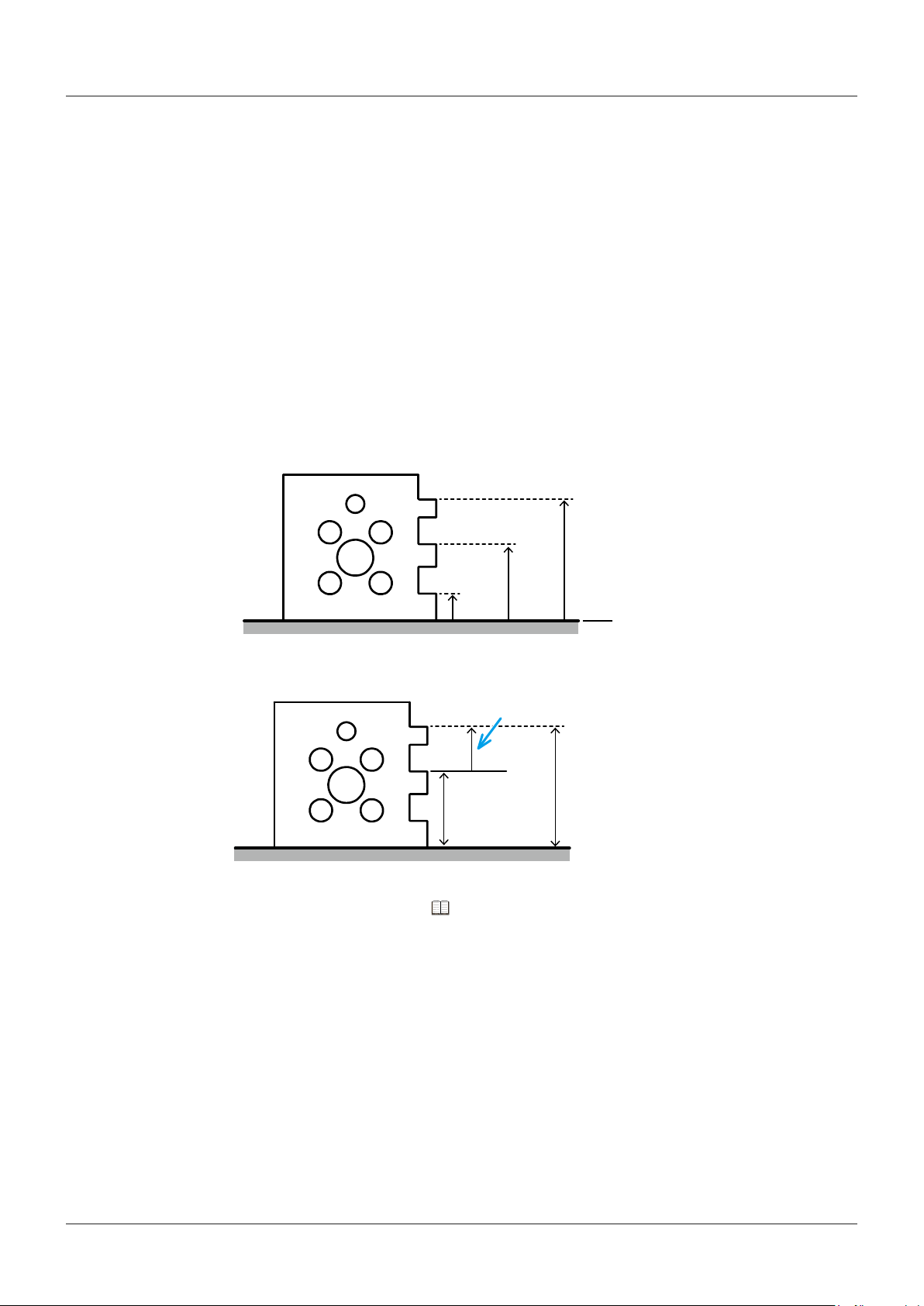
The height is calculated using the distance moved by the bottom surface of the sphere attached to the
tip of the probe. (See the left figure below.)
However, when measuring by making contact with the top surface of the sphere, the height will be
measured by adding the diameter of the sphere to the distance moved by the bottom surface of the
sphere. (See the right figure below.)
Top surface measurement
a1
Bottom surface measurement
a1
Surface a1 height = Distance moved by the bottom
surface of the sphere
The diameter of the sphere must be set in advance. The following procedure explains how to measure
the diameter of the sphere using the provided ball diameter calibration block. This procedure is
necessary if you are using the product for the first time or if you are replacing the probe.
Tips
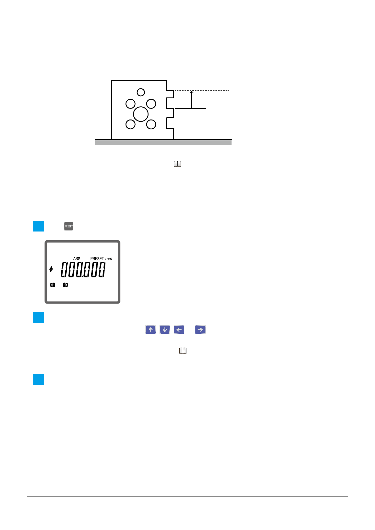
Press .
1
»Characters and icons will be displayed in the bottom row of the LCD screen.
Press to select (probe settings).
2
Press .
3
»
Slowly bring the probe into contact with the following position on the ball diameter calibration block until
4
If using a gauge block, use one with a height of 20 mm or more.
will be displayed on the upper left of the LCD screen.
Origin
Surface a1 height = Distance moved by the bottom
surface of the sphere + diameter of the sphere
Origin
a beep sound is made.
»
will be displayed on the upper left of the LCD screen.
14
No. 99MAF029B
Page 27

1 Before Using This Product
Slowly bring the probe into contact with the following position on the ball diameter calibration block until
5
a beep sound is made.
Press .
6
»The probe diameter setting is complete.
NOTE
• The actual dimensions of the sphere diameter and the measured value may not match.
• When measuring, calculates the diameter of the sphere and displays the result. The moment the
probe is brought into contact with the workpiece, a beep will sound, and the displayed value may
appear to jump, but this is not a malfunction.
15
No. 99MAF029B
Page 28

1 Before Using This Product
16
No. 99MAF029B
Page 29

2 Basic Measuring Methods
2
Using the following workpiece as an example, the height, width, inner diameter, outer diameter, and
plane displacement measuring methods will be explained. Before measuring, prepare by setting the
origin, etc.
Tips
Basic Measuring Methods
For details about preparing measurements, "1.4 Preparing Measurements" (page 10)
2.1
There are 2 types of height measurement: One where the probe is brought into contact with the top
surface of the workpiece, and one where the probe is brought into contact with the bottom surface of
the workpiece. As an example, the procedure for measuring top surface height A (85 mm) and bottom
surface height B (115 mm), shown below, using the surface plate as the ABS origin is explained.
Tips
Press and hold to change to the ABS origin setting.
1
»[ABS] will be displayed on the LCD screen.
Measuring the Height
Top surface measurement
a1
A (85 mm)
For details about ABS origin, "1.4.1 Origin Setup" (page 10)
ABS origin ABS origin
Bottom surface measurement
a1
B (115 mm)
17
No. 99MAF029B
Page 30

2 Basic Measuring Methods
a1
Bring the probe into contact with surface a1 until a beep sound is made.
2
Maintain contact between the probe and the surface a1.
Top surface measurement Bottom surface measurement
a1
»When the measurement is complete, [H] and the measured value are displayed on the LCD screen.
Tips
Confirm the measurement.
3
Top surface measurement Bottom surface measurement
If the product is connected to any external devices, the measurement results will be automatically
output. For details, "3.9 Outputting Measurement Results to an External Device" (page 47)
18
No. 99MAF029B
Page 31

2 Basic Measuring Methods
a2
2.2
Measure the steps and the width of the grooves. As an example, the procedure for measuring the step
of A (10 mm) and the groove width of B (30 mm), shown below, using a1 as the INC origin is explained.
Tips
Press to change to the INC origin setting.
1
»[INC] will be displayed on the LCD screen.
Bring the probe into contact with surface a1 until a beep sound is made.
2
Measuring the Width
Step measurement
A (10 mm)
For details about INC origin, "1.4.1 Origin Setup" (page 10)
a2
a1
INC origin
Groove width measurement
B (30 mm)
a2
a1
INC origin
Step measurement Groove width measurement
a1
»[0.000] will be displayed on the LCD screen.
Bring the probe into contact with surface a2 until a beep sound is made.
3
Maintain contact between the probe and the surface a2.
Step measurement Groove width measurement
a2
a1
»When the measurement is complete, [H] and the measured value are displayed on the LCD screen.
19
No. 99MAF029B
Page 32

2 Basic Measuring Methods
Tips
Confirm the measurement.
4
Step measurement Groove width measurement
If the product is connected to any external devices, the measurement results will be automatically
output. For details, "3.9 Outputting Measurement Results to an External Device" (page 47)
20
No. 99MAF029B
Page 33

2 Basic Measuring Methods
2.3
Measure the diameter (inner diameter) of a hole. For the inner diameter measurement, obtain the
lowest and highest points of the hole to measure the distance. As an example, the procedure for
measuring the inner diameter of A (40 mm), shown below, is explained.
Tips
Press .
1
Measuring the Inner Diameter
Highest point
A (40 mm)
Lowest point
Depending on the method set for terminating the scanning measurement, the operating procedures
vary slightly. First, confirm the method set for terminating the scanning measurement. For details
about changing the settings, "3.4 Setting the Terminating Method for Scanning Measurements"
(page 43)
ABS origin
»
will be displayed on the upper left of the LCD screen.
Obtain the lowest point of the hole.
2
If the scanning measurement termination method is set to [Auto] (automatic termination)
Face the probe towards the left or right
1
of the center bottom surface of the hole,
and slowly bring it into contact with the
surface until a beep sound is made.
Maintain contact between the probe and
the surface.
»[0.000] will be displayed on the LCD
screen.
NOTE
2
Bring the probe into contact
within 0.5 mm of the lowest point.
Measuring with a wider range may
increase measurement errors.
Secure the probe up/down wheel with
your hand or the clamp screw in order to
prevent it from moving.
21
No. 99MAF029B
Page 34

2 Basic Measuring Methods
Move the probe left or right so that it
3
passes the center of the bottom surface
of the hole. Perform this action until a
beep sound is made.
»The measurement of the
lowest point is complete, and
will be displayed on the
upper left of the LCD screen.
If you have tightened the clamp screw,
4
loosen it.
If the scanning measurement termination method is set to [ENTER] (manual termination)
Face the probe towards the center of the
1
bottom surface of the hole, and slowly
bring it into contact with the surface until
a beep sound is made.
Maintain contact between the probe and
the surface.
»[0.000] will be displayed on the
LCD screen.
Secure the probe up/down wheel with
2
your hand or the clamp screw in order to
prevent it from moving.
Repeatedly move the probe left and
3
right.
»The value displayed on the
LCD screen will change based
on the vertical movement of
the probe.
When the displayed value stops
4
changing, press .
»The measurement of the
lowest point is complete, and
will be displayed on the
upper left of the LCD screen.
22
No. 99MAF029B
Page 35

2 Basic Measuring Methods
If you have tightened the clamp screw,
5
loosen it.
Obtain the highest point of the hole.
3
If the scanning measurement termination method is set to [Auto] (automatic termination)
Face the probe towards the left or right
1
of the center top surface of the hole,
and slowly bring it into contact with the
surface until a beep sound is made.
Maintain contact between the probe and
the surface.
»[0.000] will be displayed on the LCD
screen.
NOTE
2
3
4
If the scanning measurement termination method is set to [ENTER] (manual termination)
1
Bring the probe into contact within
0.5 mm of the highest point.
Measuring with a wider range may
increase measurement errors.
Secure the probe up/down wheel with
your hand or the clamp screw in order to
prevent it from moving.
Move the probe left or right so that it
passes the center of the top surface of
the hole. Perform this action until a beep
sound is made.
»The measurement of the
highest point is complete.
If you have tightened the clamp screw,
loosen it.
Face the probe towards the center of the
top surface of the hole, and slowly bring
it into contact with the surface until a
beep sound is made.
Maintain contact between the probe and
the surface.
Secure the probe up/down wheel with
2
your hand or the clamp screw in order to
prevent it from moving.
23
No. 99MAF029B
Page 36

2 Basic Measuring Methods
Repeatedly move the probe left and
3
right.
»The value displayed on the
LCD screen will change based
on the vertical movement of
the probe.
When the displayed value stops
4
changing, press .
»The measurement of the
highest point is complete.
If you have tightened the clamp screw,
5
loosen it.
Confirm the measurement.
4
Tips
To continue measuring press ; to finish measuring press .
5
If the product is connected to any external devices, the measurement results will be automatically
output. For details, "3.9 Outputting Measurement Results to an External Device" (page 47)
24
No. 99MAF029B
Page 37

2 Basic Measuring Methods
2.4
Measure the diameter (outer diameter) of a cylinder. For the outer diameter measurement, obtain the
lowest and highest point of the cylinder to measure the distance. As an example, the procedure for
measuring the outer diameter of A (20 mm), shown below, is explained.
Tips
Press .
1
Measuring the Outer Diameter
A (20 mm)
Depending on the method set for terminating the scanning measurement, the operating procedures
vary slightly. First, confirm the method set for terminating the scanning measurement. For details
about changing the settings, "3.4 Setting the Terminating Method for Scanning Measurements"
(page 43)
Highest point
Lowest point
ABS origin
» will be displayed on the upper left of the LCD screen.
Obtain the lowest point of the cylinder.
2
If the scanning measurement termination method is set to [Auto] (automatic termination)
Face the probe towards the left or right of
1
the center bottom surface of the cylinder,
and slowly bring it into contact with the
surface until a beep sound is made.
Maintain contact between the probe and
the surface.
»[0.000] will be displayed on the LCD
screen.
NOTE
2
Bring the probe into contact
within 0.5 mm of the lowest point.
Measuring with a wider range may
increase measurement errors.
Secure the probe up/down wheel with
your hand or the clamp screw in order to
prevent it from moving.
25
No. 99MAF029B
Page 38

2 Basic Measuring Methods
Move the probe left or right so that it
3
passes the center of the bottom surface
of the cylinder. Perform this action until a
beep sound is made.
»The measurement of the
lowest point is complete, and
will be displayed on the
upper left of the LCD screen.
If you have tightened the clamp screw,
4
loosen it.
If the scanning measurement termination method is set to [ENTER] (manual termination)
Face the probe towards the center of the
1
bottom surface of the cylinder, and slowly
bring it into contact with the surface until
a beep sound is made.
Maintain contact between the probe and
the surface.
»[0.000] will be displayed on the LCD
screen.
Secure the probe up/down wheel with
2
your hand or the clamp screw in order to
prevent it from moving.
Repeatedly move the probe left and
3
right.
»The value displayed on the
LCD screen will change based
on the vertical movement of
the probe.
When the displayed value stops
4
changing, press .
»The measurement of the
lowest point is complete, and
will be displayed on the
upper left of the LCD screen.
26
No. 99MAF029B
Page 39

2 Basic Measuring Methods
If you have tightened the clamp screw,
5
loosen it.
Obtain the highest point of the cylinder.
3
If the scanning measurement termination method is set to [Auto] (automatic termination)
Face the probe towards the left or right
1
of the center top surface of the cylinder,
and slowly bring it into contact with the
surface until a beep sound is made.
Maintain contact between the probe and
the surface.
»[0.000] will be displayed on the LCD
screen.
NOTE
2
3
4
If the scanning measurement termination method is set to [ENTER] (manual termination)
1
Bring the probe into contact within
0.5 mm of the highest point.
Measuring with a wider range may
increase measurement errors.
Secure the probe up/down wheel with
your hand or the clamp screw in order to
prevent it from moving.
Move the probe left or right so that it
passes the center of the top surface of
the cylinder. Perform this action until a
beep sound is made.
»The measurement of the
highest point is complete.
If you have tightened the clamp screw,
loosen it.
Face the probe towards the center of the
top surface of the cylinder, and slowly
bring it into contact with the surface until
a beep sound is made.
Maintain contact between the probe and
the surface.
Secure the probe up/down wheel with
2
your hand or the clamp screw in order to
prevent it from moving.
27
No. 99MAF029B
Page 40

2 Basic Measuring Methods
Repeatedly move the probe left and
3
right.
»The value displayed on the
LCD screen will change based
on the vertical movement of
the probe.
When the displayed value stops
4
changing, press .
»The measurement of the
highest point is complete.
If you have tightened the clamp screw,
5
loosen it.
Confirm the measurement.
4
Tips
To continue measuring press ; to finish measuring press .
5
If the product is connected to any external devices, the measurement results will be automatically
output. For details, "3.9 Outputting Measurement Results to an External Device" (page 47)
28
No. 99MAF029B
Page 41

2 Basic Measuring Methods
2.5
Measuring the Plane Displacement (Plane Scanning Measurement)
Moving the probe while maintaining contact with the surface of the workpiece obtains multiple
measurements. Based on the acquired data, the maximum, minimum, and displacement values
(maximum – minimum = displacement) can be measured.
As an example, the procedure for measuring the displacement of a1 (maximum value), a2 (minimum
value), and A (1 mm), shown below, is explained.
a1
a2
ABS origin
NOTE
A (1 mm)
Measure within a range of about 1 mm from the starting point. Measuring with a wider range may
increase measurement errors.
Press .
1
»
will be displayed on the upper left of the LCD screen.
Begin measuring.
2
Slowly bring the probe into contact with
1
the measuring surface until a beep
sound is made.
Maintain contact between the probe and
the surface.
»[0.000] will be displayed on the
LCD screen.
Secure the probe up/down wheel with
2
your hand or the clamp screw in order to
prevent it from moving.
1 mm
29
No. 99MAF029B
Page 42

2 Basic Measuring Methods
Move the probe while maintaining
3
contact with the surface of the workpiece.
»The value displayed on the
LCD screen will change based
on the unevenness of the
workpiece.
When the displayed value stops
4
changing, press .
»The measurement is complete.
Tips
Check the measurement result.
3
1
Tips
2
If the product is connected
to any external devices, the
measurement results will be
automatically output. For details,
"3.9 Outputting Measurement
Results to an External Device"
(page 47)
Press or .
»With each key press, the value
displayed on the LCD screen will
change among displacement (W),
minimum (ZS), maximum (ZL).
The difference between the
median displacement value and
the previous measurement will be
displayed in the bottom row of the
LCD screen.
If you have tightened the clamp screw,
loosen it.
To continue measuring press ; to finish measuring press .
4
30
No. 99MAF029B
Page 43

3 Specific Usage Applications
3
3.1
Specific Usage Applications
Calculating the Difference Between 2 Measurements
There are multiple methods for determining the measurement difference. Use the method that matches
your application.
yDifference with the previous measurement
The difference between the current and immediately prior measurements will automatically be
displayed in the bottom row of the LCD screen. For example, if the previous measurement was 25
mm and the current measurement is 45 mm, [20.000] will be displayed.
The difference with the previous measurement can be checked simply by reading the value
displayed in the bottom row.
Tips
yDifference with a user-defined point
A user-defined point can be set as the comparison point for measurements. For example, set the
surface plate as the origin, and then while continually making measurements, the distance relative
to the surface plate will be displayed each time in the bottom row of the LCD screen.
Tips
yDifference between two measurements stored in memory
The two measurements are stored in the product's internal memory, and the difference between
the two values is calculated. This memory storage method is useful for when you cannot calculate
the measurement difference using the 2 previously described methods, such as obtaining a
measurement difference with a value obtained 2 measurements ago.
Tips
For details, "3.1.1 Determining the Difference Between the Most Recently Measured Value"
(page 32)
For details, "3.1.2 Continuously Measuring the Distance from One Specific Point to Multiple
Other Points" (page 33)
For details, "3.1.3 Calculating the Difference Between Values Stored in the Memory" (page
35)
31
No. 99MAF029B
Page 44

3 Specific Usage Applications
3.1.1 Determining the Difference Between the Most Recently Measured Value
Check the difference between the current and previous measurement by observing the value in
the bottom row of the LCD screen. As an example, with the surface plate set as the ABS origin, the
heights of a1, a2, and a3 are measured in that order, and the difference for each measurement can be
checked.
a3
Tips
Press and hold to change to the ABS origin setting.
1
»[ABS] will be displayed on the LCD screen.
Measure the height of a1.
2
• For details about ABS origin, "1.4.1 Origin Setup" (page 10)
• For details about measuring height,
• If an inner diameter, outer diameter, or plane scanning measurement is made, the median
measurement will be used for comparisons. For example, if the inner diameter is measured
sequentially for circles s1 and s2, the difference displayed in the bottom row of the LCD screen will
be calculated using the median values (centers) of circle s1 and s2.
"2.1 Measuring the Height" (page 17)
a1
25 mm
a2
45 mm
67 mm
ABS origin
Measure the height of a2.
3
»The difference with a1 is displayed in the bottom row.
32
No. 99MAF029B
Page 45

3 Specific Usage Applications
Measure the height of a3.
4
»The difference with a2 is displayed in the bottom row.
3.1.2 Continuously Measuring the Distance from One Specific Point to Multiple Other Points
Set an arbitrary point as the origin, and proceed to measure the distance continuously from that point.
As an example, the procedure for continuously obtaining the distance between a1 (center height of
circle s1) and a2 (center height of circle s2) shown below with the surface plate set as the origin is
explained.
NOTE
Set the origin point.
1
1
Tips
The following values can be set as the origin point.
• Height measurement
• Median value of an inner or outer diameter measurement
• Median, minimum, or maximum value of a plane scanning measurement
Slowly bring the probe into contact with the surface plate until a beep sound is made.
Maintain contact with the probe.
• Perform the same operation even if a point other than the height of the surface plate is set as the
origin point. (Bring the probe into contact with the point to set as the origin.)
• To set an inner diameter, outer diameter, or plane scanning measurement as the origin point, make
the appropriate measurement. For details,
"2.4 Measuring the Outer Diameter" (page 25), "2.5 Measuring the Plane Displacement (Plane
Scanning Measurement)" (page 29)
s2
s1
a2
a1
10 mm
"2.3 Measuring the Inner Diameter" (page 21),
30 mm
ABS origin
33
No. 99MAF029B
Page 46

3 Specific Usage Applications
With the measurement displayed, press and hold until a beep sound is made.
2
»The surface plate is set as the origin.
Tips
Measure the inner diameter of s1.
2
»The distance between the surface plate and a1 is displayed in the bottom row.
Tips
• If you measured an inner or outer diameter in step 1, the median of that diameter will be set as the
origin point. If you made a plane scanning measurement, display the value that you want to set as
the origin point (median, minimum, maximum), and then press and hold .
• If you reversed the counting direction, follow the procedure in
to reset the origin.
• If following the procedure in
hold until a beep sound is made, and then perform the procedure.
• Removing the batteries or the AC adapter (optional accessory) cable will erase the origin setting.
• For details about measuring inner diameters, "2.3 Measuring the Inner Diameter" (page 21)
• If inner diameter, outer diameter, or plane scanning measurements are made, the median
measurement will be set as the target value for determining distance.
"1.4.1 Origin Setup" (page 10) to reset the origin, first press and
"1.4.1 Origin Setup" (page 10)
Measure the inner diameter of s2.
3
»The distance between the surface plate and a2 is displayed in the bottom row.
Press and hold until a beep sound is made.
4
»The origin setting is canceled, and the product returns to normal measuring mode.
34
No. 99MAF029B
Page 47

3 Specific Usage Applications
3.1.3 Calculating the Difference Between Values Stored in the Memory
Store 2 measurements in the internal memory of the product, and then calculate the difference
between them. Any measurements that are stored in the memory and are no longer needed can be
erased as needed.
Tips
Calculating the difference between 2 values stored in the memory
As an example, the procedure for calculating the distance between a1 and a3 (42 mm), with the
surface plate set as the ABS origin and heights measured at a1, a2, and a3, is explained.
Tips
Press and hold to change to the ABS origin setting.
1
Removing the batteries or the AC adapter (optional accessory) cable will erase any values stored in
the memory.
a1
42 mm
a3
25 mm
For details about ABS origin, "1.4.1 Origin Setup" (page 10)
a2
45 mm
67 mm
ABS origin
»[ABS] will be displayed on the LCD screen.
Measure the height of a1.
2
Tips
With the measurement for a1 displayed, press and hold until a beep sound is made.
3
»The a1 measurement is stored in memory, and [M1] (memory 1), which shows the location of storage in the
Measure the height of a2.
4
Measure the height of a3.
5
For details about measuring height, "2.1 Measuring the Height" (page 17)
memory, is displayed on the bottom left of the LCD screen.
35
No. 99MAF029B
Page 48

3 Specific Usage Applications
With the measurement for a3 displayed, press and hold until a beep sound is made.
6
»Measurement a3 is stored in the memory, and [M2] (memory 2), which indicates the location of storage in the
memory, is displayed on the bottom left of the LCD screen.
Press .
7
Proceed to the next step, and determine the difference between the two values stored in memory.
Press 2 times.
8
»Characters will be displayed in the bottom row of the LCD screen.
Press to select [M1/-M2] (memory calculation).
9
»The difference between [M1] and [M2] will be displayed.
Tips
Press 2 times.
10
Erasing the measurement from memory
Press 2 times.
1
If you want to check the proportional difference between 2 measurements, press . The value of [M1]
divided by [M2] will be displayed.
»Characters will be displayed in the bottom row of the LCD screen.
Press to select [M.CLR] (memory clear).
2
»[M1] and [M2] will be displayed on the lower left of the LCD screen.
Tips
If measurements are not stored in memory, [M1], [M2], and [M.CLR] will not be displayed.
36
No. 99MAF029B
Page 49

3 Specific Usage Applications
Erase the measurements stored in the memory.
3
Erasing both [M1] and [M2] from memory
Press .
1
Erasing only either [M1] or [M2] from memory
Press or to select the target for deletion, and then press .
1
Press .
4
37
No. 99MAF029B
Page 50

3 Specific Usage Applications
3.2
By setting the upper and lower tolerance limits in advance, the acceptability judgment can be
automatically performed. The acceptability judgment will be displayed on the LED and the LCD screen,
meaning it can be easily determined whether the value falls within the tolerance range.
Operation panel
Red: Upper tolerance limit exceeded.
Orange: Lower tolerance limit exceeded.
Green: Within the tolerance range.
To perform the acceptability judgment automatically, register the upper and lower tolerance limits, and
then enable the acceptability judgment function.
Tips
Judging the Tolerance
LCD screen
You can change the length of time that the LED is lit. For details about changing the settings, "3.8
Setting the LED Lighting Time" (page 46)
[+NG]: Upper tolerance limit exceeded.
[-NG]: Lower tolerance limit exceeded.
[GO]: Within the tolerance range.
3.2.1 Setting the Upper and Lower Limits
For example, the procedure for setting the upper [+0.010 mm] and lower [–0.005 mm] tolerance limits
is explained below.
Tips
Press .
1
»Characters and icons will be displayed in the bottom row of the LCD screen.
Press to select [TOL.] (tolerance setting).
2
»[U] and the current upper limit will be displayed on the LCD screen.
Press to make [+] flash.
3
If [–] is displayed, press or to change it to [+].
• The set values are retained in memory even if the power is turned off.
• Be sure to set the upper limit value to a numeric value larger than the lower limit value. If a smaller
value is set, there will be an error.
38
No. 99MAF029B
Page 51

3 Specific Usage Applications
Repeatedly press until the 2nd value from the right flashes.
4
Press or to display [1], and then press .
5
»[L] and the current lower limit will be displayed on the LCD screen.
Press to make [–] flash.
6
If [+] is displayed, press or to change the display to [–].
Display [5] in the thousandths place using the same procedure described in steps
7
press
»Setup is complete.
.
3.2.2 Enabling/Disabling the Judgment Function
Press .
1
»Characters and icons will be displayed in the bottom row of the LCD screen.
Press to select [TOL.] (tolerance setting).
2
»[U] and the current upper limit will be displayed on the LCD screen.
Press .
3
4
and 5, and
Press or , to select [toL.on] (enabled) or [toL.oFF] (disabled), and then press .
4
Press .
5
39
No. 99MAF029B
Page 52

3 Specific Usage Applications
3.3
For example, if you want to make measurements in the following order: height at 4 points, inner
diameter at 4 points, and outer diameter at 2 points. When performing multiple measurements in a
set order, it is beneficial to register the procedure. Because the measurements are automatically
performed following the order of the registered procedure, the overall operation is simplified.
The following measurement functions can be registered.
yInner diameter measurement
yOuter diameter measurement
yPlane scanning measurement
yBottom surface measurement
yTop surface measurement
Tips
Simplifying Measurement Procedures
For details about each measurement function, "2 Basic Measuring Methods" (page 17)
3.3.1 Registering a Measurement Procedure
Select the measurement functions, such as height and inner diameter, in the order they will be used,
and register them. Up to 10 steps can be registered.
Press 2 times.
1
»Characters will be displayed in the bottom row of the LCD screen.
Press to select [ASSIST] (assist function).
2
Press or to select [ENTER STEP], and then press .
3
40
No. 99MAF029B
Page 53

3 Specific Usage Applications
Register a measurement procedure.
4
Refer to the following table. Press the key for the first measurement to be performed.
1
Measurement
function
Inner diameter
measurement
Outer diameter
measurement
Plane scanning
measurement
Bottom surface
measurement
Top surface
measurement
For example, to register an top surface measurement, press . In this case, [5] will be displayed for the
measurement function number.
Setting key
Measurement
function number
1
2
3
4
5
»Registering the first measurement is complete, and the flashing cursor moves to the right.
Register the subsequent steps using the same method.
2
»Setting the 10th step completes the registration. The measurement function registered to the 1st step will
then automatically run.
Tips
Proceed to step 4 in "3.3.2 Measuring Using a Registered Measurement Procedure" (page 42) to
5
make the measurements.
To register 9 or fewer steps, press to complete the registration process. The measurement
function registered to the 1st step will then automatically run.
Press to terminate the operation.
41
No. 99MAF029B
Page 54

3 Specific Usage Applications
3.3.2 Measuring Using a Registered Measurement Procedure
Press 2 times.
1
»Characters will be displayed in the bottom row of the LCD screen.
Press to select [ASSIST] (assist function).
2
Press or to select [RUN], and then press .
3
»The first registered measurement will be automatically performed.
Make the measurements.
4
Make the first measurement.
1
»The first registered measurement will finish, and then the second registered measurement will be
performed.
Tips
2
• For inner diameter, outer diameter, or plane scanning measurements, press to proceed to the
next registered measurement.
• For details about making measurements,
Make the subsequent measurements.
»When the 10th measurement is made, all measurements will be finished.
"2 Basic Measuring Methods" (page 17)
To continue measuring press ; to finish measuring press .
5
42
No. 99MAF029B
Page 55

3 Specific Usage Applications
3.4
Setting the Terminating Method for Scanning Measurements
A scanning measurement obtains multiple measurements by moving the probe while maintaining
contact with the workpiece and calculates values such as the maximum and minimum values from
among the measurements. This section explains how to specify the termination method for scanning
measurements. This setting is applicable to inner and outer diameter measurements.
Tips
Press .
1
»Characters and icons will be displayed in the bottom row of the LCD screen.
Press to select (probe settings).
2
Press or to display the following screen.
3
[Auto] (automatic termination) is the default setting.
Press or to select the setting, and then press .
4
Setting Details
[ENTER]
[Auto] The scanning measurement automatically terminates when the probe elevates
»Setup is complete.
NOTE
If [Auto] (automatic termination) is set, ensure that the probe is set to pass through the lowest and
highest points of the hole or cylinder. An accurate measurement result cannot be obtained if the probe
does not pass through the lowest and highest points.
Press
about 0.5 mm from the lowest point or lowers about 0.5 mm from the highest
point of the hole or cylinder. When the measurement is complete, a beep sound is
made.
to manually terminate the scanning measurement.
43
No. 99MAF029B
Page 56

3 Specific Usage Applications
3.5
You can hold a measurement on the display. Even if the probe moves away from the workpiece, the
displayed value will not change until you release the hold function. This function is applicable to height
and width measurements.
Measure the height or width.
1
»[H] and the measurement will be displayed on the LCD screen.
Tips
Press while [H] and the current measurement are displayed.
2
»The displayed value is held.
Tips
Holding the Displayed Measurement Results
For details about measuring height and width, "2.1 Measuring the Height" (page 17) and
"2.2 Measuring the Width" (page 19)
• Press again to release the display.
• Even if you output measurement results to this product from externally connected devices, the
display will not be released.
3.6
You can change the smallest reading (resolution) that the measuring instrument will display on the
LCD screen.
Tips
Press .
1
»Characters and icons will be displayed in the bottom row of the LCD screen.
Press to select [RES.] (resolution setting).
2
Press or to select the setting, and then press .
3
Setting the Resolution for Measurements
The default setting is [0.001 mm] for models that support millimeters and [0.00005 in] for models that
support inches.
»Setup is complete.
44
No. 99MAF029B
Page 57

3 Specific Usage Applications
3.7
Setting the Time Until the Power Turns Off (AutoOff)
Auto-off is a function that automatically turns off the product if it is not used for a specified period of
time. This section explains how to set the length of time that must pass before the auto-off function is
activated.
Tips
Press 2 times.
1
»Characters will be displayed in the bottom row of the LCD screen.
Press to select [POWER SET] (power setting).
2
Press or to select the setting, and then press .
3
[2min] The power is turned off if there is no operation for 2 minutes.
[5min] The power is turned off if there is no operation for 5 minutes.
[oFF] Disables the auto-off function.
[2min] (2 minutes) is the default setting.
Setting Details
»Setup is complete.
45
No. 99MAF029B
Page 58

3 Specific Usage Applications
3.8
Sets the time that the LED lights for tolerance judgment. If the battery is quickly depleted, we
recommend changing the setting so that the LED is off.
Tips
Press 2 times.
1
»Characters will be displayed in the bottom row of the LCD screen.
Press to select [POWER SET] (power setting).
2
Press or to display [LEd].
3
Press or to select the setting, and then press .
4
[3 SEc] Lights for 3 seconds.
[ALL] Stays continuously lit.
[oFF] Turns off the light.
Setting the LED Lighting Time
[3 SEc] (3 seconds) is the default setting.
Setting Details
»Setup is complete.
46
No. 99MAF029B
Page 59

3 Specific Usage Applications
3.9
Outputting Measurement Results to an External Device
Depending on the application of the measurement results data can be output to the optional mini
printer or sent to the PC.
3.9.1 Outputting to a Mini Printer (Optional Accessory)
Connecting the optional Digimatic mini-processor (DP-1VR, etc.) to the Digimatic output connector of
this product will allow you to output measurement results. The measurement results will automatically
be output upon completion of measuring. However, you can also output data by pressing .
NOTE
Tips
You can output measurement results when they are displayed. There is no output during a scanning
measurement.
• You can also output measurement results by using optional external devices. For details, see the
accompanying manual for the Digimatic mini-processor.
• By default, the product is set to output the value displayed in the top row of the LCD screen. Use
the following procedure to change the setting to the bottom row.
Press .
1
»Characters and icons will be displayed in the bottom row of the LCD screen.
Press to select [OUTPUT] (output setting).
2
Press or to select the bottom row, and then press .
3
»Setup is complete.
• If the resolution for models that support inches is set to [0.00005 in], you can change which digits
in the measurement are output. By default, the lowest 6 digits are set to be output. For example, in
[22.12345 in], [2.12345 in] will be output. Use the following procedure to change the output to the
highest 6 digits.
Press .
1
»Characters and icons will be displayed in the bottom row of the LCD screen.
Press to select [OUTPUT] (output setting).
2
Press or .
3
Press or to select [88.8888] (the first 6 digits), and then press .
4
»Setup is complete.
47
No. 99MAF029B
Page 60

3 Specific Usage Applications
3.9.2 Outputting to a PC (Windows Only)
By connecting this product to your Windows PC using a micro USB cable, you can send measurement
results to the PC. Results can be output to commercially-available communication software.
Before sending the data, the communication driver must be installed on the PC. The system
requirements for the communication driver are provided below.
Items Operating environment
OS Windows 8/Windows 7/Windows Vista/Windows XP SP3
HDD capacity 500 KB or more
Display 800 x 600 resolution or higher, 256 colors or more
Other yCommunication software such as Hyper Terminal is required.
yWe recommend using the standard USB port on the main unit (the usage of
other USB ports are not officially supported).
yInternet access is required.
Tips
Installing the communication driver on your PC
Download the communication driver from our website.
1
http://www.mitutoyo.co.jp/global.html
Install the downloaded driver on the PC.
2
Sending can also be done using the optional USB input tool, U-WAVE, etc. For details, see the
accompanying manual for each product.
48
No. 99MAF029B
Page 61

3 Specific Usage Applications
Sending the measurement results to your PC
Connect the product to your PC using a commercially available micro USB cable.
1
Tips
Start up communication software such as Hyper Terminal on the PC.
2
Tips
Make a measurement.
3
»The measurement results will be automatically sent to the PC.
Tips
When the cable is plugged in, the product is in the USB communication state, which depletes the
battery. Remove the cable when not in use.
The communication setups for the communication software should be subject to "5.3.1
Communication Specification" (page 59).
• For details about measurement methods, "2 Basic Measuring Methods" (page 17)
• You can also send the measurement results by pressing
.
49
No. 99MAF029B
Page 62

3 Specific Usage Applications
50
No. 99MAF029B
Page 63

4 Troubleshooting
4
If a problem occurs while using this product, please try one of the solutions provided below. If the
solution does not work, contact our service department via your dealer for repair.
4.1
Based on the problem, determine the cause and the solution.
The power does not turn
on when
The battery quickly
depletes.
Troubleshooting
If the Following Problem Occurs
Problem Cause Solution
is pressed.
yThe batteries are not
inserted correctly.
yThe AC adapter
(optional accessory) is
not properly connected.
The LED is set for
continuous use.
yReinsert the batteries.
yReconnect the AC adapter (optional
accessory).
yChange the setting of the LED lighting.
Tips
For details, "3.8 Setting the LED
Lighting Time" (page 46)
The air-float function does
not work (
when the air-float switch
is pressed).
Measurements are not
made even when the
probe comes in contact
with a workpiece (there is
no beep sound).
The displayed value
is being held, and the
workpiece cannot be
measured ([H] is displayed
on the LCD screen).
There is variance in the
measurements.
is only lit
yRemove the batteries if the product will not
be used for an extended period of time.
The batteries are too low
for the air-float function to
operate.
The clamp knob is locked. Loosen the clamp knob.
yThe displayed value is
held.
yThe clamp knob is
locked.
yThe probe clamp knob
is loosened.
yThe probe contacted
the workpiece with
excessive force.
yReplace all 4 batteries with new ones.
yConnect an AC adapter (optional accessory).
Tips
yPress
yFollow the instructions in "When the
displayed value is held, and the workpiece
cannot be measured" (page 52) to loosen
the clamp knob.
yTighten the probe clamp knob.
ySlowly bring the probe into contact with the
workpiece.
• The air-float function uses an
excessive amount of electricity. If
you use this function often, using the
optional AC adapter is recommended.
• When using the air-float function, the
battery life (until the air-float no longer
functions) is around 1.5 hours.
to release the hold function.
51
No. 99MAF029B
Page 64

4 Troubleshooting
Problem Cause Solution
The probe vibrates when
making plane scanning
measurements.
yThe displayed values
flicker or disappear
temporarily.
yAn accurate
measurement result
cannot be obtained.
yThe power is turned off
automatically.
When the displayed value is held, and the workpiece cannot be measured
Ensure that metal fitting A of the probe is in the center between metal fitting B and C.
The probe may vibrate
depending on the
condition of the surface of
the workpiece.
The product is used in
environments where
electromagnetic
interference exceeds
requirements defined in
the EMC Directive.
Change the movement direction of the probe,
and if the vibration stops, limit the movements
to that direction.
yThe product will return to normal after
removing the electromagnetic interference
caused by electrostatic discharge.
yIf this problem is due to electromagnetic
interference acting on the AC or DC power
line, check the circumference of the power
line, and then make a measurement again.
yIf a brownout occurs, the product will return
to normal after the recovery from the low
voltage.
B
Clamp knob
If metal fitting A is not in the center, turn the clamp knob left, and move metal fitting A vertically into
the center. From this position, turn the clamp knob right as far as possible, and then turn it left about 5
rotations. The hold function will be released, and measurements can be made again.
A
C
52
No. 99MAF029B
Page 65

4 Troubleshooting
4.2
Based on the error displayed on the LCD screen, determine the cause and the solution.
Err-30F The displayed value exceeds the
Err-90t The lower limit set for the tolerance
If Error Messages Are Displayed
Error message Cause Solution
A battery has died. yReplace all 4 batteries with new
ones.
yConnect an AC adapter (optional
accessory).
This error will automatically be
yXXX XXE
(X is an arbitrary
value)
yErr-48A
number of displayable digits.
Positioning detection sensor error
(e.g.: a foreign substance is present
or an impact caused misalignment)
is higher than the upper limit.
corrected when the value falls within
the displayable range.
The sensor may have a failure. If the
display is not restored even when the
probe is stopped, contact the nearest
Mitutoyo sales office or service center.
Set the lower limit so that it is below
the upper limit.
Tips
For details, "3.2.1 Setting
the Upper and Lower Limits"
(page 38)
Err-96P A negative value is set for the probe
diameter.
Err-40S A critical error has occurred. Contact our service department via
Retry the probe diameter setting.
Tips
your dealer for repair.
For details, "1.4.2 Setting
the Probe Diameter" (page
14)
53
No. 99MAF029B
Page 66

4 Troubleshooting
54
No. 99MAF029B
Page 67

5 Specifications
5
5.1
Code No. Metric 518-230 518-232 518-234 518-236
Model
number
Measuring range (Stroke) 0 to 465 mm
Resolution Metric 0.001 mm / 0.005 mm
Accuracy
(20 C)
Perpendicularity (forward
and backward direction)
(20 C)
Guiding method Roller bearing
Driving method Manual (wheel drive)
Detection method Electromagnetic induction absolute encoder
Measuring force 1.5 ± 0.5 N
Data output Digimatic output / USB
Air-float
Power supply AA alkaline batteries x 4 (included), AC adapter (optional),
Estimated battery life
Mass (kg) 25 kg 29 kg 25 kg 29 kg
Dimensions (mm)
Operating temperature
range (recommended)
Specifications
Basic Specifications
Inch/Metric 518-231 518-233 518-235 518-237
Metric QMH-350A QMH-600A QMH-350B QMH-600B
Inch/Metric QMH-14"A QMH-24"A QMH-14"B QMH-24"B
0 to 715 mm
(350 mm/14")
Inch/Metric 0.001 mm / 0.005 mm / 0.00005" / 0.0001" / 0.0002"
Indication
accuracy
Repeatability
*1
*1
*2
*6
7 µm 12 µm 7 µm 12 µm
rechargeable nickel-hydride batteries x 4 are supported
When the LED is not set to
constantly lit
About 300 hours (continuous use)
About 20 days (regular use: 5 hrs/
day)
LED constantly lit
About 100 hours (continuous use)
About 13.5 days (regular use: 5 hrs/
day)
If the air-float function is not used on air-float equipped models, the battery
life will be approximately the same as models without the air-float function.
If the constant LED or air-float functions will be frequently used, the
optional AC adapter is recommended.
QMH-350A/QMH-350B/QMH-14"A/QMH-14"B: 280 (W) x 273 (D) x 784 (H)
QMH-600A/QMH-600B/QMH-24"A/QMH-24"B: 280 (W) x 273 (D) x 1016 (H)
(600 mm/24")
N/A
±
(2.4 + 2.1 L/600) µm
2 σ ≤ 1.8 µm
0 to 40 C (10 to 30 C)
0 to 465 mm
(350 mm/14")
*3
Available (only for the purpose of
moving the unit)
LED not set to constantly lit and the
air-float used for half an hour per day
About 80 hours (continuous use)
About 3.3 days (regular use: 5 hrs/
day)
If the LED is constantly lit and the
air-float function is used, the battery
life will be reduced to about 2/3 of
the above value.
0 to 715 mm
(600 mm/24")
*4
*5
55
No. 99MAF029B
Page 68

5 Specifications
Operating humidity range 20 to 80% RH (with no condensation)
Storage temperature
range
Storage humidity range 5 to 90% RH (with no condensation)
CE marking EMC Directive EN61326-1
*1
The indication accuracy and repeatability indicate the values obtained from the height measurement
of a flat surface using the standard ø5 stepped probe. In the case of diameter, maximum (minimum)
value, displacement, or circular pitch measurement, the measured value may be larger than the
accuracy ratings listed in the table due to variation in the measuring force during the scanning
measurement compared to the height measurement.
*2
Perpendicularity indicates the value that is obtained from the measurement of a flat surface placed
parallel with the datum base using the Lever Head (MLH-521) and Mu-checker (M-551).
*3
A communication driver is required.
It can be downloaded from our homepage. http://www.mitutoyo.co.jp/global.html
For details, please refer to the instruction manual.
*4
To use models equipped with the air-float function, use a surface plate of JIS1 Class or above. If a
scratched or uneven surface is used, the specified performance may not be achieved.
*5
The AC adapter cannot be used to recharge rechargeable batteries.
*6
The life of the battery will vary depending on how the product is used.
Recommended nickel hydride batteries: 1,900 mAh or greater capacity
–10 C to 50 C
Immunity test requirement: Clause 6.2 Table 2
Emission limit: Class B
RoHS Directive EN50581
56
No. 99MAF029B
Page 69

5 Specifications
5.2
Digimatic Data Output Specification
5.2.1 Data Format
Output order
d1 d2 d3 d4 d5 d6 d7 d8 d9 d10 d11 d12 d13
Al l "F" (1111) Sign
(Output example)
(Provisions)
(Example) At a normal measurement of 0.123 mm
"d1" "d2" "d3" "d13"
0
1
2
→
2
3
→
→
2
2
2
1111 1111 1111 1111 0000 0000 0000 0000 1000 0100 1100 1100 0000
MSD LSD
Measured value
+: 0 (0000)
–: 8 (0001)
0
1
2
3
0
1
→
→
→
→
2
2
→
2
2
2
→
→
2
→
2
2
Decimal point
X.X.X.X.X.X.X
3 (1100)
5 (1010)
Unit
mm 0000 inch 1000
3
2
0
1
2
→
→
2
3
→
→
2
2
2
F F F F + 0 0 0 1 2 3 3 mm
Tips
7 digits are enabled when the resolution is set to [0.00005 in]. Due to our Digimatic data output
specifications, all of these digits cannot be output simultaneously. Generally, the value in the 10s place
(the highest value position) will be excluded, and only the remaining 6 digits will be output. However,
it is possible to change the settings so that the digit with the highest value is output. For details,
"3.9.1 Outputting to a Mini Printer (Optional Accessory)" (page 47)
5.2.2 Connector Specification
Pin No. I/O Symbol
1, 10 - GND
9
10
2 O DATA
1
3 O CLOCK
4 O RD
5 I REQ
6 to 9 - (Not used)
2
Vceo=35(V)
Ic=200(mA)
3.3 (V)
22 (kΩ)
CMOS
57
No. 99MAF029B
Page 70

5 Specifications
T 2
5.2.3 Timing Chart
R D
R E Q
C K
D ATA
T 6
T 1
T 4
T 3
T 5
T1 2 sec (max)
T2, T3 Differs according to the
connected device
T4 430 µs (Typ.)
T5 200 µs (Typ.)
T6 200 µs (Typ.)
58
No. 99MAF029B
Page 71

5 Specifications
5.3
USB Data Output Specification
5.3.1 Communication Specification
Communication
method
Communication speed 9600 bps
Start bit 1
Data bit 8
Parity bit N/A
Stop bit 1
Half-duplex communication
5.3.2 Data Format
D1 Code No. "0" (fixed)
D2 Channel No. "1" (fixed)
D3 Measurement item "A" (fixed)
D4 "+" or "–" sign
D5 to D12 DATA (floating decimal point)
D13 Carriage return
5.3.3 Connector Specification
Pin No. Signal name Name
1 Vbus Power supply (5 V) from the PC
2 D– Communication with the PC (–)
3 D+ Communication with the PC (+)
4 N.C. Connected to signal GND
5 GND Signal GND
5.3.4 Data Format Examples
Unit system Resolution Output format
mm 0.001 0.123 → 01A+0000.123[CR]
0.005 0.125 → 01A+0000.125[CR]
inch 0.00005 0.12345 → 01A+00.12345[CR]
0.0001 0.1234 → 01A+000.1234[CR]
0.0002 0.1234 → 01A+000.1234[CR]
59
No. 99MAF029B
Page 72

5 Specifications
5.4
Standard accessories
*1
QMH-350A/QMH-350B/QMH-14"A/QMH-14"B only
*2
QMH-600A/QMH-600B/QMH-24"A/QMH-24"B only
*3
Products with "–1" at the end of their code numbers do not include batteries.
Accessories
Part No. Accessory name Quantity
05HZA148 ø5 stepped probe 1
12AAA715 Ball diameter calibration block 1
06AEW407 Rubber cap (A) 2
06AEW408 Rubber cap (B) 1
06AEX945 Cable clamp 1
06AEW863
06AEW864
05HAA412 Hexagonal wrench (size 5) 1
99MAF029B User's Manual 1
99MAF030M Setup Manual 1
99MAF031M Quick Reference Manual 1
*1
*2
- AA alkaline batteries
- Certificate of Inspection 1
- Warranty Card 1
Product cover 1
Product cover 1
*3
4
NOTE
Fastening parts for transportation
The supplied batteries are used only for the purpose of checking the functions and performance of the
product. Therefore, they may not fulfill the specified battery life.
Part No. Accessory name Quantity
05HZA196 Column fastening screw 2
06AEW164 Weight fastening screw 1
06AEW165 Probe fastening board 1
05HAA632 Hexagonal socket head cap screw (M6 x 25) 1
60
No. 99MAF029B
Page 73

5 Specifications
5.5
*1
The scriber is used for making measurements. It cannot be used for markings.
Optional Accessories
Part No. Accessory name
yDepth measuring probe
12AAC072 Depth probe
yInterchangeable contact point for ø5 stepped probe
957261 ø2 ball contact point (coaxial type)
957262 ø3 ball contact point (coaxial type)
957263 ø4 ball contact point (coaxial type)
957264 ø14 disk contact point
957265 ø20 disk contact point
12AAA788 ø4 ball contact point (eccentric type)
12AAA789 ø6 ball contact point (eccentric type)
ySpecial holder, special probe
12AAA792 Holder for dial gauge
12AAA793 Long holder
yAC adapter
06AEG180JA AD620JA (for Japan/U.S.)
06AEG180D AD620D (for EU)
06AEG180E AD620E (for England)
06AEG180K AD620K (for Korea)
06AEG180DC AD620DC (for China)
yDigimatic connection cable
936937 1 m
965014 2 m
yOthers
05HZA143 9 x 9 adapter (the following clamp is required)
05GZA033 Clamp (for 9 x 9 adapter)
05HZA144 6.35 x 12.7 adapter (the following clamp is required)
901385 Clamp (for 6.35 x 12.7 adapter)
02AZE990 U-WAVE mounting plate
05HZA173 Scriber
*1
NOTE
The gauge blocks may be required for zero-setting depending on the probes and contact points to be
used.
61
No. 99MAF029B
Page 74

5 Specifications
62
No. 99MAF029B
Page 75

SERVICE NETWORK
*As of December 2016
Europe
Mitutoyo Europe GmbH
Borsigstrasse 8-10, 41469 Neuss, GERMANY
TEL: 49 (0)2137 102-0 FAX: 49 (0)2137 102-351
Mitutoyo CTL Germany GmbH
Von-Gunzert-Strasse 17, 78727 Oberndorf,
GERMANY
TEL: 49 (0)7423 8776-0 FAX: 49 (0)7423
8776-99
KOMEG Industrielle Messtechnik GmbH
Zum Wasserwerk 3, 66333 Völklingen,
GERMANY
TEL: 49 (0)6898 91110 FAX: 49 (0)6898 9111100
Germany
Mitutoyo Deutschland GmbH
Borsigstrasse 8-10, 41469 Neuss, GERMANY
TEL: 49 (0)2137 102-0 FAX: 49 (0)2137 86 85
M3 Solution Center Hamburg
Tempowerkring 9·im HIT-Technologiepark
21079 Hamburg, GERMANY
TEL: 49 (0)40 791894-0 FAX: 49 (0)40 791894-50
M3 Solution Center Berlin
Paradiesstrasse 208, 12526 Berlin, GERMANY
TEL:49(0)30 2611 267 FAX:49(0)30 26 29 209
M3 Solution Center Eisenach
Heinrich-Ehrhardt-Platz 1, 99817
Eisenach,GERMANY
TEL: 49 (0)3691 88909-0 FAX: 49 (0)3691 88909-9
M3 Solution Center Ingolstadt
Marie-Curie-Strasse 1a, 85055 Ingolstadt,
GERMANY
TEL: 49 (0)841 954920 FAX: 49 (0)841 9549250
M3 Solution Center Leonberg GmbH
Steinbeisstrasse 2, 71229 Leonberg,
GERMANY
TEL: 49 (0)7152 6080-0 FAX: 49 (0)7152 608060
Mitutoyo-Messgeräte Leonberg GmbH
Heidenheimer Strasse 14, 71229 Leonberg,
GERMANY
TEL: 49 (0)7152 9237-0 FAX: 49 (0)7152 9237-29
U.K.
Mitutoyo (UK) Ltd.
Joule Road, West Point Business Park,
Andover, Hampshire SP10 3UX, UNITED
KINGDOM
TEL: 44 (0)1264 353 123 FAX: 44 (0)1264 354883
M3 Solution Center Coventry
Unit6, Banner Park, Wickmans Drive,
Coventry, Warwickshire CV4 9XA, UNITED
KINGDOM
TEL: 44 (0)2476 426300 FAX: 44 (0)2476 426339
M3 Solution Center Halifax
Lowfields Business Park, Navigation Close,
Elland, West Yorkshire HX5 9HB, UNITED
KINGDOM
TEL: 44 (0)1422 375566 FAX: 44 (0)1422 328025
M3 Solution Center East Kilbride
The Baird Bulding, Rankine Avenue, Scottish
Enterprise Technology Park, East Killbride G75
0QF, UNITED KINGDOM
TEL: 44 (0)1355 581170 FAX: 44 (0)1355 581171
France
Mitutoyo France
Paris Nord 2-123 rue de la Belle Etoile, BP
59267 ROISSY EN FRANCE 95957 ROISSY
CDG CEDEX, FRANCE
TEL: 33 (0)149 38 35 00
M3 Solution Center LYON
Parc Mail 523, cours du 3éme millénaire,
69791 Saint-Priest, FRANCE
TEL: 33 (0)149 38 35 70
M3 Solution Center STRASBOURG
Parc de la porte Sud, Rue du pont du péage,
67118 Geispolsheim, FRANCE
TEL: 33 (0)149 38 35 80
M3 Solution Center CLUSES
Espace Scionzier 480 Avenue des Lacs,
74950 Scionzier, FRANCE
TEL: 33 (0)1 49 38 35 90
M3 Solution Center TOULOUSE
12 rue de Caulet, Cellule B08, 31300
TOULOUSE, FRANCE
TEL: 33 (0)1 49 38 42 90
No. 99MAF029B
Page 76

M3 Solution Center RENNES
ZAC Mivoie
Le Vallon
35230 Noyal-Châtillon sur Seiche, FRANCE
TEL: 33 (0)1 49 38 42 10
Italy
MITUTOYO ITALIANA S.r.l.
Corso Europa, 7 - 20020 Lainate (Ml), ITALY
TEL: 39 02 935781
FAX: 39 02 9373290•93578255
M3 Solution Center TORINO
Via Brandizzo, 133/F - 10088 Volpiano (TO),
ITALY
TEL: 39 02 93578282 FAX: 39 02 93578255
M3 Solution Center CHIETI
Contrada Santa Calcagna - 66020 Rocca S.
Giovanni (CH), ITALY
TEL: 39 02 93578280 FAX:39 02 93578255
M3 Solution Center PADOVA
Via G. Galilei 21/F - 35035 Mestrino (PD), ITALY
TEL: 39 02 93578268 FAX:39 02 93578255
Belgium / Netherlands
Mitutoyo BeNeLux
Mitutoyo Belgium N.V.
Hogenakkerhoekstraat 8, 9150 Kruibeke,
BELGIUM
TEL: 32 (0)3-2540444 FAX: 32(0)3-2540445
Mitutoyo Nederland B.V.
Wiltonstraat 25, 3905 KW Veenendaal,
THE NETHERLANDS
TEL: 31(0)318-534911 FAX: 31(0)318-534811
Switzerland
Mitutoyo Schweiz AG
Steinackerstrasse 35, 8902 Urdorf,
SWITZERLAND
TEL: 41 (0)447361150 FAX: 41(0)447361151
Mitutoyo Suisse SA
Rue Galilée 4, 1400 Yverdon-les Bains,
SWITZERLAND
TEL: 41 (0)244259422 FAX: 41 (0)447361151
Poland
Mitutoyo Polska Sp.z o.o.
Ul.Graniczna 8A, 54-610 Wroclaw, POLAND
TEL: 48 (0)71354 83 50 FAX: 48 (0)71354 83 55
Czech Republic
Mitutoyo Česko, s.r.o.
Dubská 1626, 415 01 Teplice, CZECH REP
TEL: 420 417-514-011 FAX: 420 417-579-867
Mitutoyo Česko M3 Solution Center
Ivančice
Ke Karlovu 62/10, 664 91 Ivančice, CZECH REP
TEL: 420 417-514-011 FAX: 420 417-579-867
Mitutoyo Česko M3 Solution Center Ostrava
Mošnov
Mošnov 314, 742 51 Mošnov, CZECH REP
TEL: 420 417-514-050 FAX:420 417-579-867
Hungary
Mitutoyo Hungária Kft.
Záhony utca 7, D-épület / fsz, 1031 Budapest,
HUNGARY
TEL: 36 (0)1 2141447 FAX: 36 (0)1 2141448
Sweden
Mitutoyo Scandinavia AB
Släntvägen 6, 194 61 Upplands Väsby,
SWEDEN
TEL: 46 (0)8 594 109 50 FAX: 46 (0)8 590 924 10
M3 Solution Center Alingsas
Ängsvaktaregatan 3A, 441 38 Alingsas,
SWEDEN
TEL: 46 (0)8 594 109 50 FAX:46 (0)322 63 31 62
M3 Solution Center Värnamo
Storgatsbacken 1, 331 30 Värnamo, SWEDEN
TEL: 46 (0)8 594 109 50 FAX: 46 (0)370 463 34
Romania
Mitutoyo Romania SRL
1A Drumul Garii Odai Street, showroom,
Ground Floor, 075100 OTOPENI-ILFOV,
ROMANIA
TEL: 40 (0)311012088 FAX: +40 (0)311012089
Showroom in Brasov
Strada Ionescu Crum Nr.1, Brasov Business
Park Turnul 1, Mezanin, 500446 BrasovJudetul Brasov, ROMANIA
TEL/FAX: 40 (0)371020017
No. 99MAF029B
Page 77

Russian Federation
Mitutoyo RUS LLC
13 Sharikopodshipnikovskaya, bld.2, 115088
Moscow, RUSSIAN FEDERATION
TEL: 7 495 7450 752
Finland
Mitutoyo Scandinavia AB Finnish Branch
Viherkiitäjä 2A, 33960, Pirkkala, Finland
TEL: 358 (0)40 355 8498
Austria
Mitutoyo Austria GmbH
Johann Roithner Straße 131 A-4050 Traun,
AUSTRIA
TEL: 43 (0)7229 23850 FAX: 43 (0)7229 23850-90
Chonburi Branch / M3 Solution Center
7/1, Moo 3, Tambon Bowin, Amphur Sriracha,
Chonburi 20230, THAILAND
TEL:(66)2-080-3563 FAX:(66)3-834-5788
Amata Nakorn Branch / M3 Solution Center
700/199, Moo 1, Tambon Bankao, Amphur
Phanthong, Chonburi 20160, THAILAND
TEL:(66)2-080-3565 FAX:(66)3-846-8978
Indonesia
PT. Mitutoyo Indonesia
Head Office / M3 Solution Center
Jalan Sriwijaya No.26 Desa cibatu Kec.
Cikarang Selatan Kab. Bekasi 17530,
INDONESIA
TEL: (62)21-2962 8600 FAX: (62)21-2962 8604
Singapore
Mitutoyo Asia Pacific Pte. Ltd.
Head office / M3 Solution Center
24 Kallang Avenue, Mitutoyo Building,
SINGAPORE 339415
TEL:(65)62942211 FAX:(65)62996666
Malaysia
Mitutoyo (Malaysia) Sdn. Bhd.
Kuala Lumpur Head Office / M3 Solution
Center
Mah Sing Intergrated Industrial Park, 4, Jalan
Utarid U5/14, Section U5, 40150 Shah Alam,
Selangor, MALAYSIA
TEL:(60)3-78459318 FAX:(60)3-78459346
Penang Branch office / M3 Solution Center
No.30, Persiaran Mahsuri 1/2, Sunway Tunas,
11900 Bayan Lepas, Penang, MALAYSIA
TEL:(60)4-6411998 FAX:(60)4-6412998
Johor Branch office / M3 Solution Center
No. 70, Jalan Molek 1/28, Taman Molek, 81100
Johor Bahru, Johor, MALAYSIA
TEL:(60)7-3521626 FAX:(60)7-3521628
Thailand
Mitutoyo(Thailand)Co., Ltd.
Bangkok Head Office / M3 Solution Center
76/3-5, Chaengwattana Road, Kwaeng
Anusaowaree, Khet Bangkaen, Bangkok
10220, THAILAND
TEL:(66)2-080-3500 FAX:(66)2-521-6136
Vietnam
Mitutoyo Vietnam Co., Ltd
Hanoi Head Office / M3 Solution Center
No. 07-TT4, My Dinh - Me Tri Urban Zone, My
Dinh 1 Ward, Nam Tu Liem District, Hanoi,
VIETNAM
TEL:(84)4-3768-8963 FAX:(84)4-3768-8960
Ho Chi Minh City Branch Office / M3
Solution Center
123 Dien Bien Phu Street,Ward 15,Binh Thanh
District, Ho Chi Minh City, VIETNAM
TEL:(84)8-3840-3489 FAX:(84)8-3840-3498
Mitutoyo Philippines, Inc.
Unit 2103, Bldg 2 GMV Building 2, 107 North
Main Avenue, Laguna Technopark, Binan,
Laguna 4024, Philippines
TEL:(63)49 544 0272 FAX:(63)49 544 0272
India
Mitutoyo South Asia Pvt. Ltd.
Head Office / M3 Solution Center
C-122, Okhla Industrial Area, Phase-l, New
Delhi-110 020, INDIA
TEL:91(11)2637-2090 FAX:91(11)2637-2636
MSA Gurgaon technical center
Plot No. 65, Phase-IV, Udyog Vihar, Gurgaon
– 122016
TEL : 91 (0124) – 2340294
Mumbai Region Head office
303, Sentinel Hiranandani Business Park
Powai, Mumbai-400 076, INDIA
TEL:91(22)2570-0684, 837, 839
FAX:91(22)2570-0685
No. 99MAF029B
Page 78

Pune Office / M3 Solution Center
G2/G3, Pride Kumar Senate, F.P. No. 402 Off.
Senapati Bapat Road, Pune-411 016, INDIA
TEL:91(20)6603-3643, 45, 46
FAX:91(20)6603-3644
Vadodara office
S-1&S-2, Olive Complex, Nr. Haveli,
Nizampura, Vadodara-390 002, INDIA
TEL: 91 265-2750781 FAX: (91) 265-2750782
Bengaluru Region Head office / M3 Solution
Center
No. 5, 100 Ft. Road, 17th Main, Koramangala,
4th Block, Bengaluru-560 034, INDIA
TEL:91(80)2563-0946, 47, 48
FAX:91(80)2563-0949
Chennai Office / M3 Solution Center
No. 624, Anna Salai Teynampet, Chennai-600
018, INDIA
TEL:91(44)2432-8823, 24, 27, 28
FAX:91(44)2432-8825
Kolkata Office
Unit No. 1208,Om Tower, 32,J.L..Nehru Road,
Kolkata-700 071, INDIA
Tel: 91 33-22267088/40060635
Fax: (91) 33-22266817
Taiwan
Mitutoyo Taiwan Co., Ltd. / M3 Solution
Center Taipei
4F., No.71, Zhouzi St., Neihu Dist.,Taipei City
114, TAIWAN (R.O.C.)
TEL:886(2)5573-5902 FAX:886(2)8752-3267
Taichung Branch / M3 Solution Center
Taichung
1F., No.758, Zhongming S. Rd., South Dist.,
Taichung City 402, TAIWAN(R.O.C.)
TEL:886(4)2262-9188 FAX:886(4) 2262-9166
Kaohsiung Branch / M3 Solution Center
Kaohsiung
1F., No.31-1, Haibian Rd., Lingya Dist.,
Kaohsiung City 802, Taiwan (R.O.C.)
TEL:886(7)334-6168 FAX:886(7)334-6160
South Korea
Mitutoyo Korea Corporation
Head Office / M3 Solution Center
(Sanbon-Dong, Geumjeong High View Build.),
6F, 153-8, Ls-Ro, Gunpo-Si, Gyeonggi-Do,
15808 KOREA
TEL:82(31)361-4200 FAX:82(31)361-4202
Busan Office / M3 Solution Center
(3150-3, Daejeo 2-dong) 8,Yutongdanji 1-ro
49beon-gil, Gangseo-gu, Busan, 46721
KOREA
TEL:82(51)718-2140 FAX:82(51)324-0104
Daegu Office / M3 Solution Center
371-12, Hosan-Dong, Dalseo-Gu, Daegu,
42704, KOREA
TEL:82(53)593-5602 FAX:82(53)593-5603
China
Mitutoyo Measuring Instruments (Shanghai)
Co., Ltd.
12F, Nextage Business Center, No.1111 Pudong
South Road, Pudong New District ,Shanghai
200120, CHINA
TEL:86(21)5836-0718 FAX:86(21)5836-0717
Suzhou Office / M3 Solution Center China
(Suzhou)
No. 46 Baiyu Road, Suzhou 215021, CHINA
TEL:86(512)6522-1790 FAX:86(512)6251-3420
Wuhan Office
RM. 1701, Wuhan Wanda Center, No. 96,
Linjiang Road, Wuchang District, Wuhan Hubei
430060, CHINA
TEL:86(27)8544-8631 FAX:86(27)8544-6227
Chengdu Office
1-705, New Angle Plaza, 668# Jindong
Road, Jinjiang District, Chengdu, Sichuan
610066,CHINA
TEL:86(28)8671-8936 FAX:86(28)8671-9086
Hangzhou Office
RM.804, Eastern International Business
Center Building 1, No.600 Jinsha Road
Hangzhou Economic and Technological
Development Zone, 310018, China
TEL: 86(571)8288-0319 FAX: 86(571)8288-0320
Tianjin Office / M3 Solution Center Tianjin
RM. A+B+C 15/F, TEDA Building, No.256 Jiefang Nan Road Hexi District,Tianjin 300042,
CHINA
TEL:86(22)5888-1700 FAX:86(22)5888-1701
Changchun Office
RM.1801, Kaifa Dasha, No. 5188 Ziyou
Avenue, Changchun 130013, CHINA
TEL:86(431)8461-2510 FAX:86(431)8464-4411
Qingdao Office / M3 Solution Center Qingdao
Room 638, 6F, No.192 Zhengyang Road,
Chengyang District, Qingdao, Shandong,
266109, CHINA
TEL:86(532)8096-1936 FAX:86(532)8096-1937
No. 99MAF029B
Page 79

Xiʼan Office
RM. 805, Xiʼan International Trade Center, No.
196 Xiaozhai East Road, Xiʼan, 710061, CHINA
TEL:86(29)8538-1380 FAX:86(29)8538-1381
Dalian Office / M3 Solution Center Dalian
RM.1008, Grand Central IFC, No.128 Jin ma
Road,Economic Development Zone,Dalian
116600, CHINA
TEL:86(411)8718 1212 FAX:86(411)8754-7587
Zhengzhou Office
Room1801,18/F,Unit1,Building No.23,
Shangwu Inner Ring Road, Zhengdong New
District,Zhengzhou City,Henan Province,
450018,CHINA
TEL:86(371)6097-6436 FAX:86(371)6097-6981
Mitutoyo Leeport Metrology (Hong Kong)
Limited
Rm 818, 8/F, Vanta Industrial Centre, No.21-33,
Tai Lin Pai Road, Kwai Chung, NT, Hong Kong
TEL:86(852)2992-2088 FAX:86(852)2670-2488
Mitutoyo Leeport Metrology (Dongguan)
Limited /
M3 Solution Center Dongguan
No.26, Guan Chang Road, Chong Tou Zone,
Chang An Town, Dong Guan, 523855 CHINA
TEL:86(769)8541 7715 FAX:86(769)-8541 7745
Mitutoyo Leeport Metrology (Dongguan)
Limited – Fuzhou office
Rm 2104, City Commercial Centre, No.129 Wu
Yi Road N., Fuzhou City, Fujian Province, CHINA
TEL 86 591 8761 8095 FAX 86 591 8761 8096
Mitutoyo Leeport Metrology (Dongguan)
Limited –Changsha office
Room 2207, Shiner International Plaza, No. 88,
Kaiyuan Middle Road, Changsha City, Hunan,
China
TEL 86 731 8401 9276 FAX 86 731 8401 9376
Mitutoyo Measuring Instruments (Suzhou)
Co., Ltd.
No. 46 Baiyu Road, Suzhou 215021, CHINA
TEL:86(512)6252-2660 FAX:86(512)6252-2580
U.S.A.
Mitutoyo America Corporation
965 Corporate Boulevard, Aurora, IL 60502,
U.S.A.
TEL:1-(630)820-9666 Toll Free No.
1-(888)648-8869
FAX:1-(630)978-3501
M3 Solution Center-Illinois
965 Corporate Boulevard, Aurora, IL 60502,
U.S.A.
TEL:1-(888)648-8869 FAX:1-(630)978-3501
M3 Solution Center-Ohio
6220 Hi-Tek Court, Mason, OH 45040, U.S.A.
TEL:1-(888)648-8869 FAX:1-(513)754-0718
M3 Solution Center-Michigan
44768 Helm Street, Plymouth, MI 48170,
U.S.A.
TEL:1-(888)648-8869 FAX:1-(734)459-0455
M3 Solution Center-California
16925 E. Gale Avenue, City of Industry, CA
91745, U.S.A.
TEL:1-(888)648-8869 FAX:1-(626)369-3352
M3 Solution Center-North Carolina
11515 Vanstory Drive, Suite 140, Huntersville,
NC 28078, U.S.A.
TEL:1-(888)648-8869 FAX:1-(704)875-9273
M3 Solution Center-Alabama
2100 Riverchase Center, Suite 106, Hoover,
AL 35244, U.S.A
TEL:1-(888)648-8869 FAX:1-(205)988-3423
M3 Solution Center-Washington
1000 SW 34th Street Suite G, Renton WA
98057 U.S.A.
TEL:1-(888)648-8869
M3 Solution Center-Texas
4560 Kendrick Plaza Drive, Suite 120,
Houston, TX 77032, U.S.A.
TEL:1-(888)648-8869 FAX:1-(281)227-0937
M3 Solution Center-Massachusetts
753 Forest Street, Suite 110, Marlborough,MA
01752, U.S.A.
TEL:1-(888)648-8869 FAX:1-(508)485-0782
Mitutoyo America Corporation Calibration
Lab
965 Corporate Boulevard, Aurora, IL 60502,
U.S.A.
TEL:1-(888)648-8869 FAX:1-(630)978-6477
Micro Encoder, Inc.
11533 NE 118th Street, Kirkland, WA 98034,
U.S.A.
TEL:1-(425)821-3906 FAX:1-(425)821-3228
Micro Encoder Los Angeles, Inc.
16925 E. Gale Avenue, City of Industry, CA
91745 U.S.A.
TEL:1-(626)271-1075
No. 99MAF029B
Page 80

Canada
Mitutoyo Canada Inc.
2121 Meadowvale Blvd., Mississauga, Ont.
L5N 5N1., CANADA
TEL:1-(905)821-1261 FAX:1-(905)821-4968
Montreal Office
7075 Place Robert-Joncas Suite 129,
Montreal, Quebec H4M 2Z2, CANADA
TEL:1-(514)337-5994 FAX:1-(514)337-4498
Brazil
Mitutoyo Sul Americana Ltda.
AV. Joao Carlos da Silva Borges, 1240 - CEP
04726-002 - Santo Amaro -São Paulo - SP,
BRASIL
TEL:55(11)5643-0000 FAX:55(11)5641-3722
Regional Office
Belo Horizonte - MG
TEL:55(31)3531-5511 FAX:55(31)3594-4482
Rio Grande do Sul / PR, SC
TEL/FAX:55(51)3342-1498
TEL:55(51)3337-0206
Rio de Janeiro - RJ
TEL:55(21)3333-4899
TEL/FAX:55(21)2401-9958
Santa Barbara DʼOeste - SP
TEL:55(19)3455-2062 FAX:55(19)3454-6103
Norte, Nordeste, Centro Oeste
TEL:55(11)5643-0060 FAX:55(11)5641-9029
Escritorio BA / SE
TEL/FAX:55(71)3326-5232
Factory(Suzano)
Rodovia Índio Tibirica 1555, BAIRRO RAFFO,
CEP 08620-000 SUZANO-SP, BRASIL
TEL:55(11)4746-5858 FAX:55(11)4746-5936
Mexico
Mitutoyo Mexicana, S. A. de C. V
Prolongación Industria Eléctrica No. 15 Parque
Industrial Naucalpan
Naucalpan de Juárez, Estado de México C.P.
53370, MÉXICO
TEL: 52 (01-55) 5312-5612
M3 Solution Center Monterrey
Av. Morones Prieto No 914, Oriente Local,
105 Plaza Matz Col. La Huerta, C.P. 67140
Guadalupe, N.L.., MÉXICO
TEL: 52 (01-81) 8398-8227, 8398-8228,
8398-8244, 8398-8245 and 8398-8246
FAX: 52 (01-81) 8398-8245
M3 Solution Center Tijuana
Av. 2o. eje Oriente-Poniente No. 19075 Int. 18
Col. Cd. Industrial Nueva Tijuana C.P. 22500
Tijuana, B. C., MÉXICO
TEL: 52 (01-664) 647-5024
M3 Solution Center Querétaro
Av. Constituyentes Ote. 71-B, Fraccionamiento
Observatorio C.P. 76040 Querétaro, Qro.,
MÉXICO
TEL: 52 (01-442) 340-8018, 340-8019 and
340-8020
FAX: 52 (01-442) 340-8017
Aguascalientes Office / M3 Solution Center
Av. Aguascalientes No. 622, Local 15 Centro
Comercial El Cilindro Fracc. Pulgas Pandas
Norte, C.P. 20138, Aguascalientes, Ags.
MÉXICO
TEL: 52 (01-449) 174-4140 and 174-4143
Irapuato Office / M3 Solution Center
Boulevard a Villas de Irapuato No. 1460 L.1
Col. Ejido
Irapuato C.P. 36643
Irapuato, Gto., MÉXICO
TEL: 52 (01-462) 144-1200 and 144-1400
Argentina
Mitutoyo Sul Americana Ltda.
Argentina Branch
Av. B. Mitre 891/899 – C.P. (B1603CQI)
Vicente López –Pcia. Buenos Aires – Argentina
TEL:54(11)4730-1433 FAX:54(11)4730-1411
Sucursal Cordoba
Av. Amadeo Sabattini, 1296, esq. Madrid Bº
Crisol Sur – CP 5000, Cordoba, ARGENTINA
TEL/FAX:54 (351) 456-6251
No. 99MAF029B
Page 81

Revision History
Date of publication No. of revisions Revision details
2017/2/1 First edition publication
No. 99MAF029B
Page 82

Mitutoyo Corporation
20-1, Sakado 1-Chome, Takatsu-ku, Kawasaki-shi, Kanagawa 213-8533,
Japan
Home page: http://www.mitutoyo.co.jp/global.html
Printed in Japan
No. 99MAF029B
 Loading...