


ADVANCE AND EVER ADVANCING


SPLIT-TYPE, AIR CONDITIONERS
TECHNICAL & SERVICE MANUAL
<indoor unit> Service ref.
Models PED-3EJA1.UK PED-4EJSA1.UK PED-5EJSA1.UK PED-6EJSA.UK
This manual does not cover the following outdoor units. When servicing them, please refer to the service manual No.OC149B and this manual as a set.
PU-3VJC.UK
PU-3YJC.UK PU-4VLJSA2.UK PU-4YJSA2.UK PU-5YJSA.UK PU-6YJSA.UK
CONTENTS
INDOOR UNIT
1.FEATURES ··································
2.PART NAMES AND FUNCTIONS ·············· 2
3.SPECIFICATIONS ·····························
4.DATA ·······································
5.REFRIGERANT SYSTEM DIAGRAM ······· 12
6.OUTLINES AND DIMENSIONS ················· 14
7.WIRING DIAGRAM ····························
8.DISASSEMBLY INSTRUCTIONS ············· 16
9.PARTS LIST ··································
10.OPERATION FLOW-CHART ·····················
11.MICROPROCESSOR CONTROL·············· 28
12.TROUBLE SHOOTING ·························
13.OPTIONAL PARTS ····························
The Slim Line.
From Mitsubishi Electric
TM
REMOTE CONTROLLER
1
1 
 FEATURES
lndoor unit Remote controller
Models |
Cooling capacity |
|
|
W |
Btu/h |
PED-3EJA1.UK |
7,600 |
25,900 |
PED-4EJSA1.UK |
9,700 |
33,100 |
PED-5EJSA1.UK |
12,400 |
42,300 |
PED-6EJSA.UK |
14,800 |
50,400 |
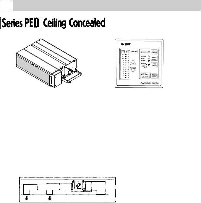
1. TOTALLY INVISIBLE INDOOR UNIT BEHIND THE CEILING
The totally hidden indoor unit that lies above the ceiling surface enables you to utilize full floor space while allowing for flexible interior design. This new feature is recommended for stores and offices where the user's own imagination is allowed to be incorporated.
2. MOST SUITABLE FOR SIMULTANEOUS TWO ROOM AIR CONDITIONING
Using air ducts for cooling airflow that matches the structure and purpose of the room, enables you to provide two air outlets for simultaneous cooling of two rooms.
Air outlet duct |
Air intake duct |
 air intake
3. HIGH EXTERNAL STATIC PRESSURE (OPTION MOTOR)
The exceptional external static pressure of 130Pa allows long ducts to be used more extensively to achieve convenient location of indoor units. (STD:70Pa)
4. DRAIN WATER LIFT-UP MECHANISM (OPTION KIT)
This allows more versatility when selecting drain piping layouts.
1

5.ADVANCED MICROPROCESSOR CONTROL
(1)Ultra - thin 12mm(1/2" )remote controller.
(2)Attractive LED display .
Every operation condition is indicated on the LED display.
(3)Simultaneous display of set temperature and room temperature.
(4)Convenient 12 - hour ON-OFF timer.
This convenient timer allows the unit to be switched on and off automatically,at the time you set. Once the timer is set,the remaining time is shown on the LED display..
(5)Self - diagnostic function indicates problems instantly on remote controller.
(6)The useful memory feature can store instructions.
The previous set value is memorized so that constant temperature control can be obtained. For example,if a power failure occurs, this feature will conveniently memorize the previous temperature and reset accordingly.
(7)There is a polar 12 core - conductor cable between the remote controller and indoor board.The cable can be extended up to 50m.(option)
2 
 PART NAMES AND FUNCTIONS
ÁIndoor Unit
Air outlet
Air intake
(sucks the air inside the room into the unit)
2

|
|
ÁRemote controller |
ÁSettings remain in effect until changed. Air |
|
conditioner can be operated by simply pushing |
|
ON/OFF button once settings have been made. |
ÁOperation buttons
(Example display readings are for explanations only ;actual display readings will differ.
3
3 
 SPECIFICATIONS
|
|
|
Model |
Item |
|
|
|
Cooling capacity |
4 |
Btu/h |
|
|
|
|
W |
Total input |
4 |
kW |
|
|
Power supply |
|
|
|
Input |
|
kW |
|
Running current |
|
A |
|
Starting current |
|
A |
|
External finish |
|
|
UNIT |
Heat exchanger |
|
|
Fan (drive) ~No. |
|
|
|
|
|
|
|
INDOOR |
Fan motor output |
1 |
kW |
Airflow (Low-High) |
|
CMM,(CFM) |
|
|
|
||
|
External static pressure |
2 |
Pa(mmAq) |
|
Operation control & Thermostat |
|
|
|
Noise level (Low-High) |
3, 5 |
dB (A) |
|
Cond. drain conn. O.D. |
|
mm, (in) |
|
|
W |
mm, (in) |
|
Dimensions |
D |
mm, (in) |
|
|
H |
mm, (in) |
|
Weight |
|
kg, (lbs) |
|
Model name |
|
|
|
Power supply |
|
|
|
Input |
|
kW |
|
Running current |
|
A |
|
Starting current |
|
A |
|
External finish |
|
|
UNIT |
Refrigerant control |
|
|
Compressor |
|
|
|
|
|
|
|
OUTDOOR |
Model |
|
|
Motor output |
|
kW |
|
|
|
||
|
Starter type |
|
|
|
Protection devices |
|
|
|
Heat exchanger |
|
|
|
Fan (drive) ~No. |
|
|
|
Fan motor output |
|
kW |
|
Airflow |
|
CMM,(CFM) |
|
Noise level |
|
dB (A) |
|
|
W |
mm, (in) |
|
Dimensions |
D |
mm, (in) |
|
|
H |
mm, (in) |
|
Weight |
|
kg, (lbs) |
REFRIGERANT PIPING |
Refrigerant |
Height difference (m) |
|
Between the indoor |
|||
|
Charge |
|
kg, (lbs) |
|
Pipe size O.D. |
Liquid |
mm, (in) |
|
|
Gas |
mm, (in) |
|
Connection method |
Indoor side |
|
|
|
Outdoor side |
|
|
& outdoor unit |
Piping length (m) |
|
PED-3EJA1.UK |
|
PED-4EJSA1.UK |
||||
|
25,900 |
|
|
33,100 |
||
|
7,600 |
|
|
9,700 |
||
|
3.60 |
|
|
3.98 |
||
|
|
~(1ph),50Hz,220-240V |
|
|
||
|
0.4 |
|
|
0.62 |
||
|
1.70 |
|
|
2.64 |
||
|
1.9 |
|
|
3.2 |
||
|
|
Galvanized sheets |
|
|
||
|
|
Plate fin coil |
|
|
||
|
|
Centrifugal (direct)x2 |
|
|
||
|
0.15 |
|
|
0.27 |
||
|
|
|
||||
20- 25(700-800) |
|
27- 34(950-1200) |
||||
|
|
70(7)/130(13) at Hi-notch |
|
|
||
|
|
Remote control&Built-in |
|
|
||
|
37-41 |
|
|
41-46 |
||
|
|
|
32(1-1/4) |
|
|
|
1175(46-1/8) |
|
1415(55-11/16) |
||||
|
740(29-1/8) |
|
740(29-1/8) |
|||
325(12-13/16) |
|
325(12-13/16) |
||||
|
44(108) |
|
|
62(137) |
||
PU-3VJC.UK |
|
PU-3YJC.UK |
|
PU-4VLJSA.UK |
|
PU-4YJSA.UK |
~(1ph) |
|
3N~(3ph,4wires) |
|
~(1ph) |
|
3N~(3ph,4wires) |
50Hz |
|
50Hz |
|
50Hz |
|
50Hz |
220-240V |
|
380-415V |
|
220-240V |
|
380-415V |
3.20 |
|
3.20 |
|
3.52 |
|
3.36 |
13.9 |
|
5.3 |
|
16.3 |
|
5.5 |
68 |
|
36 |
|
79 |
|
38 |
|
|
Munsell 5Y 7/1 |
|
|
||
|
|
Capillary tube |
|
|
||
|
|
|
Hermetic |
|
|
|
NHJ52VNDT |
|
NHJ52YDAT |
|
NH56VNDT |
|
NHJ56YDAT |
2.2 |
|
2.2 |
|
2.7 |
|
2.7 |
|
|
|
Line Start |
|
|
|
V(L) : Inner thermostat,HP switch,LP switch
Y : Reversed-phase protector,Thermal switch,Thermal relay,HP switch,LP switch
|
|
|
Plate fin coil |
|
|
|
Propeller(direct)X1 |
|
Propeller(direct)X2 |
||||
|
0.085 |
|
|
0.065+0.065 |
||
|
50(1765) |
|
|
95(3352) |
||
|
52 |
|
|
54 |
||
|
870(34-1/4) |
|
|
870(34-1/4) |
||
295+24(11-5/8 add 1) |
|
295+24(11-5/8 add 1) |
||||
|
850(33-7/16) |
|
|
1258(49-1/2) |
||
|
73(161) |
|
|
94(207) |
||
|
|
|
R-22 |
|
|
|
3.08(6.79) |
|
2.88(6.35) |
|
3.8(8.38) |
|
4.6(10.14) |
|
|
|
9.52(3/8) |
|
|
|
|
15.88(5/8) |
|
|
19.05(3/4) |
||
|
|
|
Flared |
|
|
|
|
|
|
Flared |
|
|
|
|
30 |
|
|
40 |
||
|
30 |
|
|
40 |
||
|
|
|
|
|
|
|
1. |
External |
static |
pressure |
at |
130Pa. |
4.Rating condition <JIS B 8615> |
2. |
Ex-works |
at 70Pa(OPTION MOTOR :130Pa) |
INDOOR: 27 ˚CDB, 19 ˚CWB |
|||
3. |
External |
static |
pressure |
at |
70Pa. |
OUTDOOR: 35 ˚CDB |
5.Noise level : Sound pressure level
4

|
|
|
|
Model |
Item |
|
|
|
|
Cooling capacity |
4 |
|
Btu/h |
|
|
|
|
|
W |
Total input |
4 |
|
kW |
|
|
Power supply |
|
|
|
|
Input |
|
|
kW |
|
Running current |
|
|
A |
|
Starting current |
|
|
A |
|
External finish |
|
|
|
UNIT |
Heat exchanger |
|
|
|
Fan (drive) ~No. |
|
|
|
|
|
|
|
|
|
INDOOR |
Fan motor output |
1 |
|
kW |
Airflow (Low-High) |
|
CMM,(CFM) |
||
|
|
|||
|
External static pressure |
2 |
Pa(mmAq) |
|
|
Operation control & Thermostat |
|
|
|
|
Noise level (Low-High) |
3, 5 |
|
dB (A) |
|
Cond. drain conn. O.D. |
|
mm, (in) |
|
|
|
W |
mm, (in) |
|
|
Dimensions |
D |
mm, (in) |
|
|
|
H |
mm, (in) |
|
|
Weight |
|
kg, (lbs) |
|
|
Model name |
|
|
|
|
Power supply |
|
|
|
|
Input |
|
|
kW |
|
Running current |
|
|
A |
|
Starting current |
|
|
A |
|
External finish |
|
|
|
UNIT |
Refrigerant control |
|
|
|
Compressor |
|
|
|
|
|
|
|
|
|
OUTDOOR |
Model |
|
|
|
Motor output |
|
|
kW |
|
|
|
|
||
|
Starter type |
|
|
|
|
Protection devices |
|
|
|
|
Heat exchanger |
|
|
|
|
Fan (drive) ~No. |
|
|
|
|
Fan moter output |
|
|
kW |
|
Airflow |
|
CMM,(CFM) |
|
|
Noise level |
|
|
dB (A) |
|
|
W |
mm, (in) |
|
|
Dimensions |
D |
mm, (in) |
|
|
|
H |
mm, (in) |
|
|
Weight |
|
kg, (lbs) |
|
REFRIGERANT PIPING |
Refrigerant |
Height difference(m) |
||
Between the indoor |
||||
|
Charge |
|
kg, (lbs) |
|
|
Pipe size O.D. |
Liquid |
mm, (in) |
|
|
|
Gas |
mm, (in) |
|
|
Connection method |
Indoor side |
|
|
|
|
Outdoor side |
|
|
|
& outdoor unit |
Piping length |
(m) |
|
PED-5EJSA1.UK |
|
PED-6EJSA.UK |
42,300 |
50,400 |
|
12,400 |
14,800 |
|
5.3 |
5.84 |
|
|
~(1ph),50Hz,220-240V |
|
0.64 |
|
0.66 |
2.72 |
|
2.79 |
6.0 |
|
6.25 |
|
Galvanized sheets |
|
|
Plate fin coil |
|
|
Centrifugal (direct)x2 |
|
0.40 |
|
|
|
0.30 |
|
33.5- 42(1180-1480) |
|
36.5- 46(1280-1620) |
|
70(7)/130(13) at Hi-notch |
|
|
Remote control&Built-in |
|
44-50 |
|
46-51 |
|
32(1-1/4) |
|
1415(55-11/16) |
|
1715(67-1/2) |
740(29-1/8) |
|
740(29-1/8) |
325(12-13/16) |
|
325(12-13/16) |
65(143) |
|
70(154) |
PU-5YJSA.UK |
|
PU-6YJSA.UK |
3N~(3ph,4wires) |
|
3N~(3ph,4wires) |
50Hz |
|
50Hz |
380-415V |
|
380-415V |
4.66 |
|
5.18 |
7.63 |
|
8.48 |
65.5 |
|
74 |
|
Munsell 5Y 7/1 |
|
|
Capillary tube |
|
|
Hermetic |
|
ZR61KCTFD |
|
ZR72KCTFD |
3.5 |
|
4.2 |
|
Line Start |
|
Y : Reversed-phase protector,Thermal switch,Thermal relay,HP switch,LP switch
|
Plate fin coil |
|
|
Propeller(direct)X2 |
|
0.065+0.065 |
|
0.065+0.065 |
100(3529) |
|
100(3529) |
55 |
|
56 |
970 |
|
970 |
345+24(13-9/16 add 1) |
|
345+24(13-9/16 add 1) |
1258(49-1/2) |
|
1258(49-1/2) |
114(251) |
|
117(258) |
|
R-22 |
|
5.1(11.24) |
|
5.7(12.57) |
|
9.52(3/8) |
|
|
19.05(3/4) |
|
|
Flared |
|
|
Flared |
|
45 |
|
45 |
45 |
|
45 |
|
|
|
1. |
External |
static |
pressure |
at |
130Pa. |
4.Rating condition < JIS B 8615 > |
||
2. |
Ex-works |
at 70Pa(OPTION MOTOR :130Pa) |
INDOOR: 27 |
DB, 19 |
WB |
|||
3. |
External |
static |
pressure |
at |
70Pa. |
OUTDOOR: 35 |
DB |
|
|
|
|
|
|
|
5.Noise level : Sound |
pressure level |
|
5

4 
 DATA
DATA
1. PERFORMANCE DATA
1) COOLING CAPACITY
|
Indoor |
|
|
|
|
|
|
|
|
|
|
|
|
|
|
|
|
|
|
Service Ref. |
intake air |
20 |
|
25 |
|
30 |
|
35 |
|
40 |
|
45 |
|
||||||
|
WB˚C |
|
|
|
|
|
|
|
|
|
|
|
|
|
|
|
|
|
|
|
CA |
|
P.C. |
CA |
|
P.C. |
CA |
|
P.C. |
CA |
|
P.C. |
CA |
|
P.C. |
CA |
|
P.C. |
|
|
16 |
7,737 |
|
2.91 |
7,524 |
|
3.04 |
7,220 |
|
3.26 |
6,893 |
|
3.48 |
6,551 |
|
3.69 |
6,201 |
|
2.94 |
PED- |
18 |
8,231 |
|
2.98 |
8,018 |
|
3.10 |
7,691 |
|
3.34 |
7,357 |
|
3.56 |
7,007 |
|
3.79 |
6,650 |
|
3.15 |
3EJA1.UK |
20 |
8,732 |
|
3.02 |
8,527 |
|
3.16 |
8,193 |
|
3.40 |
7,843 |
|
3.65 |
7,486 |
|
3.88 |
7,121 |
|
3.37 |
|
22 |
9,241 |
|
3.08 |
9,067 |
|
3.22 |
8,717 |
|
3.48 |
8,360 |
|
3.73 |
7,995 |
|
4.00 |
7,615 |
|
3.61 |
|
16 |
9,875 |
|
3.22 |
9,603 |
|
3.36 |
9,215 |
|
3.60 |
8,798 |
|
3.84 |
8,361 |
|
4.08 |
7,915 |
|
3.24 |
PED- |
18 |
10,505 |
|
3.29 |
10,234 |
|
3.43 |
9,816 |
|
3.69 |
9,390 |
|
3.93 |
8,943 |
|
4.19 |
8,488 |
|
3.48 |
4EJSA1.UK |
20 |
11,145 |
|
3.34 |
10,883 |
|
3.48 |
10,457 |
|
3.76 |
10,010 |
|
4.04 |
9,555 |
|
4.29 |
9,089 |
|
3.73 |
|
22 |
11,795 |
|
3.40 |
11,572 |
|
3.56 |
11,126 |
|
3.84 |
10,670 |
|
4.13 |
10,204 |
|
4.42 |
9,719 |
|
3.99 |
|
16 |
12,623 |
|
4.29 |
12,276 |
|
4.48 |
11,780 |
|
4.79 |
11,247 |
|
5.12 |
10,689 |
|
5.44 |
10,118 |
|
4.33 |
PED- |
18 |
13,429 |
|
4.38 |
13,083 |
|
4.57 |
12,549 |
|
4.91 |
12,003 |
|
5.25 |
11,433 |
|
5.58 |
10,851 |
|
4.64 |
5EJSA1.UK |
20 |
14,247 |
|
4.45 |
13,913 |
|
4.64 |
13,367 |
|
5.01 |
12,797 |
|
5.36 |
12,215 |
|
5.72 |
11,619 |
|
4.97 |
|
22 |
15,078 |
|
4.53 |
14,793 |
|
4.74 |
14,223 |
|
5.12 |
13,640 |
|
5.49 |
13,045 |
|
5.88 |
12,425 |
|
5.31 |
|
16 |
15,066 |
|
4.73 |
14,652 |
|
4.94 |
14,060 |
|
5.28 |
13,424 |
|
5.64 |
12,758 |
|
5.99 |
12,076 |
|
6.42 |
PED- |
|
|
|
|
|
|
|
|
|
|
|
|
|
|
|
|
|
|
|
18 |
16,028 |
|
4.83 |
15,615 |
|
5.04 |
14,978 |
|
5.41 |
14,326 |
|
5.78 |
13,646 |
|
6.15 |
12,951 |
|
6.54 |
|
6EJSA.UK |
20 |
17,004 |
|
4.90 |
16,606 |
|
5.11 |
15,954 |
|
5.52 |
15,274 |
|
5.91 |
14,579 |
|
6.30 |
13,868 |
|
6.77 |
|
22 |
17,996 |
|
4.99 |
17,656 |
|
5.22 |
16,976 |
|
5.64 |
16,280 |
|
6.05 |
15,570 |
|
6.48 |
1,4830 |
|
7.01 |
Note C A: Capacity(W)
P.C.: Power consumption(kW)
2) COOLING CAPACITY CORRECTION FACTORS
Service Ref. |
|
|
|
Refrigerant piping length(one way) |
|
|
|
||||
5m |
10m |
15m |
20m |
25m |
30m |
35m |
40m |
45m |
50m |
||
|
|||||||||||
PED3EJA1.UK |
1.00 |
0.978 |
0.962 |
0.948 |
0.934 |
0.921 |
- |
- |
- |
- |
|
PED4EJSA1.UK |
1.00 |
0.984 |
0.974 |
0.964 |
0.954 |
0.944 |
0.935 |
0.926 |
- |
- |
|
PED5EJSA1.UK |
1.00 |
0.978 |
0.962 |
0.948 |
0.934 |
0.921 |
0.908 |
0.896 |
0.884 |
- |
|
PED6EJSA.UK |
1.00 |
0.970 |
0.950 |
0.931 |
0.912 |
0.896 |
0.880 |
0.864 |
0.850 |
0.840 |
|
6
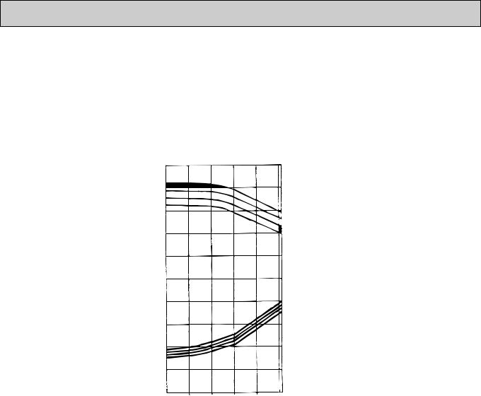
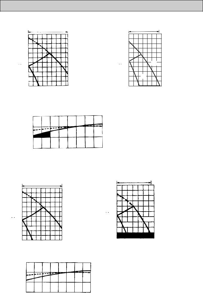
2. PERFORMANCE CURVE (CAPACITY RATIO & TOTAL INPUT RATIO)
PED-3EJA1.UK
PED-4EJSA1.UK
PED-5EJSA1.UK
PED-6EJSA.UK
CAPACITY(RATIO)
TOTAL INPUT(RATIO)
Cooling
1.4
1.2 

INDOOR WB (˚C)
1 |
22 |
20
0.8
 18 16
18 16
0.6 |
|
|
|
|
|
1.4 |
|
|
|
|
INDOOR WB (˚C) |
|
|
|
|
|
|
1.2 |
|
|
|
|
22 |
|
|
|
|
20 |
|
|
|
|
|
|
18 |
|
|
|
|
|
16 |
1 |
|
|
|
|
|
0.8 |
|
|
|
|
|
0.6 |
|
|
|
|
|
0.4 |
|
|
|
|
|
-5 |
5 |
15 |
25 |
35 |
46 |
OUTDOOR DB (˚C)
7
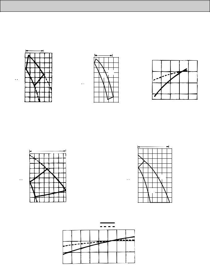
3. FAN PERFORMANCE AND CORRECTED AIR FLOW
PED-3EJA1.UK |
|
|
|
|
|
|
|
||||||
|
Fan performance <130pa> |
|
|
Fan performance <70pa> |
|||||||||
|
|
Recommended range |
|
|
|||||||||
|
|
|
|
|
|
|
|
|
|||||
|
|
200 |
|
|
|
|
|
|
Recommended range |
||||
(Pa) |
|
|
|
|
|
|
|
|
|
|
|
|
|
(1Pa0.1mmAg) |
180 |
|
|
|
|
staticExtemalpressure (Pa) |
.1mmAg)(1Pa |
180 |
|
|
|
Correctionfactor |
|
staticExtemalpressure |
20 |
|
|
|
|
20 |
|
|
|
||||
|
|
160 |
|
|
Hi |
|
|
160 |
|
|
|
|
|
|
|
140 |
Lo |
|
|
|
|
140 |
|
|
|
|
|
|
|
120 |
|
|
|
|
|
|
120 |
|
Lo |
Hi |
|
|
|
100 |
|
|
|
|
|
|
100 |
|
|
|
|
|
|
80 |
|
|
|
|
|
|
80 |
|
|
|
|
|
|
60 |
|
|
|
|
|
|
60 |
|
|
|
|
|
|
40 |
|
|
|
|
|
|
40 |
|
|
|
|
|
|
12 |
16 |
20 |
24 |
28 32 |
|
|
12 |
16 |
20 |
24 |
28 32 |
|
|
Air flow (CMM) |
|
|
Air flow (CMM) |
||||||||
Corrected Air Flow
|
|
Capacity |
|
|
|
Cooling |
|
Input |
|
1.1
1.0 |
|
|
|
|
|
0.9 |
|
|
|
|
|
0.8 |
|
|
|
|
|
12 |
16 |
20 |
24 |
28 |
32 |
Air flow (CMM)
PED-4EJSA1.UK
Extemal static pressure (Pa)
Fan performance <130pa> |
Fan performance <70pa> |
|
Recommended range |
||
|
|
|
Recommended range |
|
|
220 |
|
|
|
|
|||
|
|
|
|
|
|
|
|
|
|
|
|
|
|
200 |
|
|
|
|
(Pa) |
|
200 |
|
|
|
|
.1mmAg) |
180 |
|
|
|
|
.1mmAg) |
180 |
|
|
|
|
|
160 |
|
|
|
|
pressurestatic |
160 |
|
|
|
|
||
|
|
|
|
|
|
|
|
|
|
|
||
|
140 |
|
|
|
|
|
|
140 |
|
|
|
|
|
120 |
|
|
|
Hi |
|
|
120 |
|
|
|
|
|
100 |
|
|
|
|
|
100 |
|
|
|
Hi |
|
(1Pa |
Lo |
|
|
Extemal |
(1Pa |
|
|
Lo |
||||
80 |
|
|
80 |
|
|
|
||||||
|
|
|
|
|
|
|
|
|
|
|
||
|
60 |
|
|
|
|
|
|
60 |
|
|
|
|
|
40 |
|
|
|
|
|
|
40 |
|
|
|
|
|
20 |
|
|
|
|
|
|
20 |
|
|
|
|
|
26 |
28 |
30 |
32 |
34 36 38 40 |
|
|
24 |
26 |
28 |
30 |
32 34 36 38 |
|
Air |
flow (CMM) |
|
|
Air |
flow (CMM) |
||||||
|
|
|
|
|
Corrected Air Flow |
Capacity |
|
|
|
|
|
|
|
|
|
|
|
|
|
|
|
|
|
||
|
|
|
|
|
Cooling |
Input |
|
|
|
|
|
|
|
|
|
|
|
1.1 |
|
|
|
|
|
|
|
factor |
1.0 |
Correction |
0.9 |
|
0.8
24 |
26 |
28 |
30 |
32 |
34 |
36 |
38 |
40 |
Air flow (CMM)
8
PED-5EJSA1.UK
Fan performance <130pa> |
Fan performance <70pa> |
Recommended range |
Recommended range |
Extemal static pressure (Pa)
(1Pa 0.1mmAg)
220
200 
180
160
140
120
100 |
Hi |
|
80 |
||
|
60
Lo
40
20
32 34 36 38 40 42 44 46 48
Air flow (CMM)
|
|
220 |
|
|
(Pa) |
|
200 |
|
|
|
180 |
|
||
static pressure |
.1mmAg) |
160 |
|
|
140 |
|
|||
120 |
|
|||
100 |
Hi |
|||
Extemal |
(1Pa |
80 |
|
|
60 |
|
|||
40 |
Lo |
|||
|
|
|||
|
|
20 |
|
|
|
|
32 34 36 38 40 42 44 46 |
||
|
|
|
Air flow (CMM) |
|
Correction factor
Corrected Air Flow
|
|
Capacity |
|
|
|
Cooling |
|
Input |
|
1.1
1.0
0.9 
0.8 |
|
|
|
|
|
|
|
|
32 |
34 |
36 |
38 |
40 |
42 |
44 |
46 |
48 |
|
|
|
Air |
flow |
(CMM) |
|
|
|
PED-6EJSA.UK
Fan performance <130pa>
Recommended range
|
|
220 |
|
|
|
|
|
|
|
|
|
|
|
|
|
|
|
|
200 |
|
|
|
|
|
|
|
|
|
|
|
|
|
|
(Pa) |
|
180 |
|
|
|
|
|
|
|
|
|
|
|
|
|
|
|
160 |
|
|
|
|
|
|
|
|
|
|
|
|
|
|
|
pressurestaticExtemal |
=0.1mmAg)(1Pa |
|
|
|
|
|
|
|
|
|
|
|
|
|
|
|
140 |
|
|
|
|
|
|
|
|
|
|
|
|
|
|
||
|
|
|
|
|
|
|
|
|
|
|
|
|
|
|
|
|
|
|
120 |
|
|
|
|
|
|
|
|
|
|
|
|
|
|
|
|
100 |
|
|
|
|
|
|
|
Hi |
|
|
|
|
|
|
|
|
80 |
|
|
|
|
|
|
|
|
|
|
|
|
|
|
|
|
60 |
|
Lo |
|
|
|
|
|
|
|
|
|
|
|
|
|
|
40 |
|
|
|
|
|
|
|
|
|
|
|
|
||
|
|
|
|
|
|
|
|
|
|
|
|
|
|
|
|
|
|
|
20 |
|
|
|
|
|
|
|
|
|
|
|
|
|
|
|
|
36 38 40 |
42 |
44 |
46 |
48 |
50 52 |
|
|
|
|
|||||
|
|
|
Air |
flow (CMM) |
|
|
|
|
|
|
|
|
||||
|
|
|
|
|
|
Corrected Air Flow |
|
|
Capacity |
|||||||
|
|
|
|
|
|
|
|
|||||||||
|
|
|
1.1 |
|
Cooling |
|
|
|
|
|
|
|
|
Input |
|
|
|
|
|
|
|
|
|
|
|
|
|
|
|
||||
|
|
|
|
|
|
|
|
|
|
|
|
|
|
|||
|
|
|
|
|
|
|
|
|
|
|
|
|
|
|
|
|
|
|
factor |
1.0 |
|
|
|
|
|
|
|
|
|
|
|
|
|
|
|
Correction |
|
|
|
|
|
|
|
|
|
|
|
|
|
|
|
|
0.9 |
|
|
|
|
|
|
|
|
|
|
|
|
|
|
|
|
|
|
|
|
|
|
|
|
|
|
|
|
|
|
|
|
|
|
0.8 |
|
|
|
|
|
|
|
|
|
|
|
|
|
|
|
|
36 |
38 |
40 |
|
42 |
44 |
46 |
48 |
50 |
52 |
||||
|
|
|
|
|
|
|
|
Air |
|
flow |
(CMM) |
|
|
|
||
Fan performance <70pa>
Recommended range
|
|
200 |
|
(Pa) |
|
180 |
|
|
160 |
||
pressurestaticExtemal |
=0.1mmAg)(1Pa |
||
140 |
|||
|
|
||
|
|
120 |
100 |
|
|
80 |
Hi |
|
60 |
||
Lo |
||
40 |
||
|
20 


36 38 40 42 44 46 48 50 Air flow (CMM)
9
4. ELECTRICAL DATA
Indoor ····· 220V 50Hz 1phase
Outdoor ··· 220/380V 50Hz 1/3phases
|
Models |
Indoor |
PED-3EJA1.UK |
PED-4EJSA1.UK |
PED-5EJSA1.UK |
PED-6EJSA.UK |
|||
|
Outdoor |
PU-3VJA |
PU-3YJA |
PU-4VLJSA |
PU-4YJSA |
PU-5YJSA |
PU-6YJSA |
||
|
|
||||||||
|
|
|
|
|
|
|
|
|
|
Capacity(W) |
7,400 |
7,400 |
9,500 |
9,500 |
12,200 |
14,600 |
|||
|
|
|
|
|
|
|
|
|
|
Total input(kW) |
3.48 |
3.48 |
3.87 |
3.81 |
5.10 |
5.67 |
|||
|
|
|
|
|
|
|
|
|
|
Indoor |
Input(kW) |
0.30 |
0.30 |
0.52 |
0.52 |
0.54 |
0.56 |
||
|
|
|
|
|
|
|
|
||
Current(A) |
1.39 |
1.39 |
2.41 |
2.41 |
2.50 |
2.59 |
|||
|
|||||||||
|
|
|
|
|
|
|
|
|
|
|
Starting current(A) |
1.74 |
1.74 |
2.93 |
2.93 |
5.50 |
5.75 |
||
|
|
|
|
|
|
|
|
|
|
Outdoor |
Input(kW) |
3.18 |
3.18 |
3.35 |
3.29 |
4.56 |
5.11 |
||
|
|
|
|
|
|
|
|
||
Current(A) |
15.1 |
5.7 |
16.9 |
5.7 |
8.15 |
8.63 |
|||
|
|||||||||
|
|
|
|
|
|
|
|
|
|
|
Starting current(A) |
68 |
36 |
79 |
38 |
65.5 |
74 |
||
|
|
|
|
|
|
|
|
|
|
Indoor ····· 230V 50Hz 1phase
Outdoor ·· 230/400V 50Hz 1/3phases
|
Models |
Indoor |
PED-3EJA1.UK |
PED-4EJSA1.UK |
PED-5EJSA1.UK |
PED-6EJSA.UK |
|||
|
Outdoor |
PU-3VJA |
PU-3YJA |
PU-4VLJSA |
PU-4YJSA |
PU-5YJSA |
PU-6YJSA |
||
|
|
||||||||
|
|
|
|
|
|
|
|
|
|
Capacity(W) |
7,500 |
7,500 |
9,600 |
9,600 |
12,300 |
14,700 |
|||
|
|
|
|
|
|
|
|
|
|
Total input(kW) |
3.55 |
3.55 |
4.01 |
3.90 |
5.20 |
5.76 |
|||
|
|
|
|
|
|
|
|
|
|
Indoor |
Input(kW) |
0.35 |
0.35 |
0.57 |
0.57 |
0.59 |
0.61 |
||
|
|
|
|
|
|
|
|
||
Current(A) |
1.55 |
1.55 |
2.53 |
2.53 |
2.62 |
2.69 |
|||
|
|||||||||
|
|
|
|
|
|
|
|
|
|
|
Starting current(A) |
1.82 |
1.82 |
3.07 |
3.07 |
5.75 |
6.00 |
||
|
|
|
|
|
|
|
|
|
|
Outdoor |
Input(kW) |
3.20 |
3.20 |
3.44 |
3.33 |
4.61 |
5.15 |
||
|
|
|
|
|
|
|
|
||
Current(A) |
14.5 |
5.5 |
16.6 |
5.6 |
7.89 |
8.56 |
|||
|
|||||||||
|
|
|
|
|
|
|
|
|
|
|
Starting current(A) |
68 |
36 |
79 |
38 |
65.5 |
74 |
||
|
|
|
|
|
|
|
|
|
|
Indoor ····· 240V 50Hz 1phase
Outdoor ·· 240/415V 50Hz 1/3phases
|
Models |
Indoor |
PED-3EJA1.UK |
PED-4EJSA1.UK |
PED-5EJSA1.UK |
PED-6EJSA.UK |
|||
|
Outdoor |
PU-3VJA |
PU-3YJA |
PU-4VLJSA |
PU-4YJSA |
PU-5YJSA |
PU-6YJSA |
||
|
|
||||||||
|
|
|
|
|
|
|
|
|
|
Capacity(W) |
7,600 |
7,600 |
9,700 |
9,700 |
12,400 |
14,800 |
|||
|
|
|
|
|
|
|
|
|
|
Total input(kW) |
3.60 |
3.60 |
4.14 |
3.98 |
5.30 |
5.84 |
|||
|
|
|
|
|
|
|
|
|
|
Indoor |
Input(kW) |
0.40 |
0.40 |
0.62 |
0.62 |
0.64 |
0.66 |
||
|
|
|
|
|
|
|
|
||
Current(A) |
1.70 |
1.70 |
2.64 |
2.64 |
2.72 |
2.79 |
|||
|
|||||||||
|
|
|
|
|
|
|
|
|
|
|
Starting current(A) |
1.90 |
1.90 |
3.20 |
3.20 |
6.00 |
6.25 |
||
|
|
|
|
|
|
|
|
|
|
Outdoor |
Input(kW) |
3.20 |
3.20 |
3.52 |
3.36 |
4.66 |
5.18 |
||
|
|
|
|
|
|
|
|
||
Current(A) |
13.9 |
5.3 |
16.3 |
5.5 |
7.63 |
8.48 |
|||
|
|||||||||
|
|
|
|
|
|
|
|
|
|
|
Starting current(A) |
68 |
36 |
79 |
38 |
65.5 |
74 |
||
|
|
|
|
|
|
|
|
|
|
10

5. STANDARD OPERATION DATA (COOLING)
|
Models |
|
PED-3EJA1.UK |
PED-4EJSA1.UK |
PED-5EJSA1.UK |
PED-6EJSA.UK |
||||
|
|
|
|
|||||||
|
|
|
|
|
|
|
|
|
|
|
Total |
Capacity |
W |
7,600 |
7,600 |
9,700 |
9,700 |
12,400 |
14,800 |
||
|
|
|
|
|
|
|
|
|
||
Input |
kW |
3.60 |
3.60 |
4.14 |
3.98 |
5.30 |
5.88 |
|||
|
|
|
|
|
|
|
|
|
|
|
|
Indoor unit model |
|
PED-3EJA1 |
PED-4EJSA1 |
PED-5EJSA1 |
PED-6EJSA |
||||
|
|
|
|
|
|
|
|
|
|
|
circuit |
Phase Hz |
|
1.50 |
1.50 |
1.50 |
1.50 |
1.50 |
1.50 |
||
|
|
|
|
|
|
|
|
|
||
Volts |
|
240 |
240 |
240 |
240 |
240 |
240 |
|||
|
|
|||||||||
|
|
|
|
|
|
|
|
|
|
|
Electrical |
Amperes |
|
1.70 |
1.70 |
2.64 |
2.64 |
2.72 |
2.79 |
||
|
|
|
|
|
|
|
|
|
||
Outdoor unit-model |
|
PU-3VJC |
PU-3YJC |
PU-4VLJSA |
PU-4YJSA |
PU-5YJSA |
PU-6YJSA |
|||
|
|
|||||||||
|
|
|
|
|
|
|
|
|
|
|
|
Phase,Hz |
|
1.50 |
3.50 |
1.50 |
3.50 |
3.50 |
3.50 |
||
|
|
|
|
|
|
|
|
|
|
|
|
Volts |
|
240 |
415 |
240 |
415 |
415 |
415 |
||
|
|
|
|
|
|
|
|
|
|
|
|
Amperes |
|
13.9 |
5.3 |
16.3 |
5.5 |
7.63 |
8.47 |
||
|
|
|
|
|
|
|
|
|
|
|
circuit |
Discharge pressure |
MPa |
2.03 |
2.02 |
1.80 |
1.81 |
1.84 |
2.07 |
||
|
|
|
|
|
|
|
|
|
||
Suction pressure |
MPa |
0.50 |
0.49 |
0.52 |
0.52 |
0.40 |
0.46 |
|||
|
||||||||||
|
|
|
|
|
|
|
|
|
|
|
Refrigerant |
Discharge temperature |
˚C |
62.2 |
79.1 |
82.1 |
74.0 |
82.9 |
78.3 |
||
|
|
|
|
|
|
|
|
|
||
Condensing temperature |
˚C |
53.6 |
53.3 |
48.5 |
48.7 |
49.3 |
53.6 |
|||
|
||||||||||
|
|
|
|
|
|
|
|
|
|
|
|
Suction temperature |
˚C |
9.4 |
9.0 |
8.1 |
8.5 |
0.3 |
4.3 |
||
|
|
|
|
|
|
|
|
|
|
|
|
Ref.Pipe length |
m |
5 |
5 |
5 |
5 |
5 |
5 |
||
|
|
|
|
|
|
|
|
|
|
|
side |
Intake air temperature |
DB˚C |
27.0 |
27.0 |
27.0 |
27.0 |
27.0 |
27.0 |
||
|
|
|
|
|
|
|
||||
WB˚C |
19.0 |
19.0 |
19.0 |
19.0 |
19.0 |
19.0 |
||||
Indoor |
|
|
||||||||
|
|
|
|
|
|
|
|
|
||
Diischarge air temperature |
DB˚C |
15.5 |
14.8 |
15.7 |
16.0 |
15.5 |
13.6 |
|||
|
|
|
|
|
|
|
|
|
|
|
Outdoor side |
|
|
WB˚C |
24.0 |
24.0 |
24.0 |
24.0 |
24.0 |
24.0 |
|
|
Intake air temperature |
|
DB˚C |
35.0 |
35.0 |
35.0 |
35.0 |
35.0 |
35.0 |
|
|
|
|
|
|
|
|
|
|
||
|
|
|
|
|
|
|
|
|
||
|
SHF |
|
0.78 |
0.78 |
0.80 |
0.80 |
0.85 |
0.74 |
||
|
|
|
|
|
|
|
|
|
||
|
BF |
|
0.21 |
0.20 |
0.22 |
0.22 |
0.13 |
0.14 |
||
|
|
|
|
|
|
|
|
|
|
|
11

5 
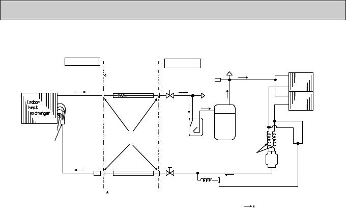
 REFRIGERANT SYSTEM DIAGRAM
PED-3EJA1.UK Indoor unit |
Refrigerant pipe |
|
(option) |
|
15.88mm(5/8) |
|
(With heat insulator) |
|
Flexible tube |
Thermistor |
|
RT2 |
Flared |
|
|
Distributor |
connection |
|
Strainer |
|
Refrigerant pipe |
|
(option) |
|
9.52mm(3/8) |
|
(With heat insulator) |
PED-4EJSA1.UK |
Indoor unit |
|
Refrigerant pipe |
|
(option) |
|
19.05mm(3/4) |
|
(With heat insulator) |
|
Flexible tube |
Thermistor |
|
RT2 |
Flared |
|
|
Distributor |
connection |
Strainer
Refrigerant pipe (option)
 9.52mm(3/8) (With heat insulator)
PED-5EJSA1.UK Indoor unit |
Refrigerant pipe |
|
|
|
(option) |
|
19.05mm(3/4) |
|
(With heat insulator) |
|
Flexible tube |
Thermistor
RT2 |
Flared |
Distributor |
connection |
|
Strainer
Refrigerant pipe (option)
 9.52mm(3/8) (With heat insulator)
Outdoor unit
PU-3V(Y)JC.UK |
|
|
|
Low pressure |
High pressure |
|
|
switch |
|
switch |
|
Ball |
Charge |
Check |
|
valve |
plug |
plug |
|
|
|
Strainer |
|
|
|
|
Outdoor heat |
|
|
*1 |
exchanger |
|
|
|
|
Accumulator |
|
Capillary tube |
|
|
(O.D.3.2XI.D.1.8-L=800)X2pcs |
||
|
|
Compressor |
|
Ball valve
(With service port)
Outdoor unit
PU-4Y(VL)JSA2.UK
Low pressure switch
*1 Capillary tube PU-3VJC(O.D.3.2XI.D.2.0-L=500) PU-3YJC(O.D.3.2XI.D.1.4-L=800)
flow of refrigerant
High pressure switch
Ball |
Charge |
Check |
valve |
plug |
plug |
Strainer
Outdoor heat exchanger
Capillary tube
Compressor
(O.D.3.2XI.D.2.0-L=840)X2pcs
Capillary tube for injection
Only PU-4YJSA(O.D.3.2XI.D.1.2-L=500)
Ball valve
(With service port)
flow of refrigerant
Outdoor unit |
Check |
PU-5YJSA2.UK |
plug |
|
|
High pressure |
|
switch |
|
Charge |
|
plug |
|
Ball |
|
valve |
|
Outdoor heat exchanger
Accumulator
Compressor
Capillary tube Ball valve (O.D.4.0XI.D.2.4-L=840)X2pcs (With service port)
Strainer
Capillary tube
O.D.4.0XI.D.2.4-L=400
flow of refrigerant
12
PED-6EJSA.UK
Indoor unit |
Refrigerant pipe |
Outdoor unit |
Check |
|
|
(option) |
PU-6YJSA.UK |
plug |
|
|
19.05mm(3/4) |
High pressure |
||
|
(With heat insulator) |
switch |
|
|
|
|
|
|
Charge |
|
Flexible tube |
Ball |
|
plug |
|
|
|
||
|
|
valve |
|
Outdoor heat |
|
|
|
|
|
|
|
|
|
exchanger |
Thermistor |
|
|
|
|
RT2 |
Flared |
Accumulator |
|
|
Distributor |
connection |
Compressor |
||
|
|
|
||
|
|
Ball valve |
|
Capillary tube |
|
|
(O.D.4.0XI.D.2.4-L=1200)X2pcs |
||
Strainer |
|
(With service port) |
||
|
|
|
|
|
|
Refrigerant pipe |
|
|
Strainer |
|
|
|
|
|
|
(option) |
Capillary tube |
||
|
9.52mm(3/8) |
|
|
O.D.4.0XI.D.2.4-L=200 |
|
(With heat insulator) |
|
|
flow of refrigerant |
|
|
|
|
|
13
 Loading...