

Page 1

Cable(100mm)
Cable(5300mm)
1
Part
name
Q'ty
Figure
1 External LEV Box 2 Joint pipe 3 Pipe cover 4 Band 5 Fastener
2 2 6 2
183
102
146
31
50
70
Cable (accessory) hole
40
122
82
200
70
Center line
Mounting plate
Remove the two screws (4 10)
Mounting plate
Install the two screws (4 10)
Center line
4-Oval hole
160
11 41
62
82
62
Center line
164
4-Oval hole
4-Oval hole
5
10
(R)
Oval hole dimension
164
Center line
wRefer to this label when connecting the on-site refrigerant pipe. Make sure to keep
the side with this label upward, and install the External LEV Box1 horizontally.
Washer (procure locally)
Washer (procure locally)
Nut (procure locally)
Nut (procure locally)
3. Set the External LEV Box1 to the
suspension bolt and tighten each
nuts and washers.
Two installation patterns are available by changing the position of the
mounting plate. Install the four screws (procure locally) in oval holes.
Install the four screws (procure locally) in oval holes.
443
295
(155)
(81)
(155)133
(81)
External LEV Box1
Joint pipe2
Connection [6.35
Connection [9.52
To Outdoor Unit
To Indoor Unit
Please keep the right direction by following the
arrows below when installing this unit.
This LEV Box must be installed horizontally, keeping
this side up.
BG79K515H02
2. Change the position of External LEV Box1 mounting plate as shown below.
The mounting plate can also be fixed to suspension bolts before it is fixed to
the External LEV Box1.
Mounting plate
Remove the two screws (4 10)
Mounting plate
Install the two screws (4 10)
Safety precautions
Precautions that should be observed to prevent injury or damage to the premises and/or contents thereof.
Warning
Caution
Precautions that should be observed to prevent serious injury or death.
• Before installing the unit, make sure to read all the “Safety precautions”.
• These precautions provide very important points regarding safety. Make sure to follow them.
• Symbols used in this manual are categorized according to the degree of risk when used improperly as follows:
Warning
•
If the unit is installed improperly, water leakage, electric shock or fire may be caused.
The unit must not be installed by the user. Ask the dealer or
an authorized company to install the unit.
Installation must be properly done following this installation manual.
•
If the unit is installed improperly, water leakage, electric shock or fire may be caused.
Caution
• Children may put plastic bags over their head. And it may cause
suffocation.
Keep plastic bags away from children.
• If piping is not properly installed, water leakage may result, which will
make the ceilings, floors or other household items wet.
Perform drain piping according to the installation manual and
make sure water is drained properly and keep drain piping
warm to prevent bedewing.
Before installation (relocation) and electrical work
• If proper electrical cables are not used, short circuit, electric shock or
fire may be caused.
Use proper electrical cables to meet the standard for current
capacity.
• Improper heat insulation may cause condensation on parts such as
pipings, and wet ceilings, floors or other valuable items.
Make sure heat insulation for refrigerant piping is properly
installed to prevent bedewing.
Inserts rated at 100-150kg each
(procure locally)
Suspension bolts M10 (3/8")(procure locally)
Steel reinforcing rod
Install the suspension bolts as shown below or install it with angles or blocks.
1. Install the suspension bolts M10 (3/8")(procure locally). Decide the installation
location referring to the figure on the right. The unit must be suspended firmly.
Package air-conditioner Optional parts
Installation Manual of EXTERNAL LEV BOX
PAC
-SG95LE-E
[For CITY MUL
T
I INDOOR UNIT 20-63 MODELS]
w Before installing the unit, make sure to read the installation manual of the indoor unit and this manual.
1
Parts check
This unit is provided with this manual and following parts in the box.
2
Installation procedure
Connect the External LEV Box to the liquid pipe and install it inside the ceiling (Do not install in an outdoor location. It may cause a
breakdown). Make sure to install the access door on the ceiling.
The installation patterns below are available. Select the installation pattern according to the preferred installation method. The
distance between indoor unit and Exter
nal LEV Box is within 5 m. (Pipe: 5m, Cable: 5.3m)
Outline of External LEV Box (Factory shipment) (Unit: mm)
Installation pattern A (Using Suspension bolts; recommended pattern) (Unit: mm)
Installation pattern B (Unit: mm) Installation pattern C (Unit: mm)
2-1 Installation location
Note: Make sure to complete installation work of External LEV Box of optional parts before turning on the indoor unit. This unit may
run improperly if the unit is not installed following this manual.
•
After installation, perform the test run to ensure normal operation. Then explain the user the "Safety Precautions", use and
maintenance of the unit based on the information in the Operation Manual. Both the Installation Manual and the Operation
Manual must be given to the user. These manuals must always be kept by the actual users.
RG79A417K01
Page 2
Flare dimensions
[
B dimensions
(mm)
A dimensions (mm)
Copper
pipe O.D.
(mm)
Clutch-style
Flare tool for R410A Flare tool for R22, R407C
Tightening torque
N.m(kgf.cm)
[B
45-
i2-
90- i0.5-
R0.4~R0.8
A
Copper
pipe
Die
0~0.5[6.35(1/4") 1.0~1.5
0~0.5 1.0~1.5[9.52(3/8")
8.7~9.1
12.8~13.2
14~18(140~180)
34~42(340~420)
External LEV Box1
30~40mm
30mm
Band4
Pipe cover3
Insulation material
for refrigerant pipe
(Procure locally)
Band4
Joint pipe
2
R410A : Only for indoor unit 63 models
R407C : Only for indoor unit 50, 63 models
Push in
Pipe cover3
Insulation material
for refrigerant pipe
Refrigerant pipe
Cross-section view of connection
Electrical box
Put the connector
in the electrical bo
x.
Indoor unit
Cable (Accessory:100mm)
Cable (Accessory:5300mm)
CN60 connector (LEV, white)
Controller board
Linear expansion valve
External LEV Box1
LEV
Electrical box
Put the connector
in the electrical bo
x.
Indoor unit
Remove
Cable (Accessory:5300mm)
CN60 connector (LEV, white)
Controller board
Lead wire of
Connector (CN60)
Relay connector
Linear expansion valve
External LEV Box1
LEV
Controller board
Connect to the CN60 connector.
Cable for External LEV Box
Electrical box
Fastener5
Use the clamp for on-site wiring under the electrical
parts box to fix the cable together with the on-site
wirings (power supply cable, transmission cable and
remote controller cable).
Example: PKFY-P.VBM-E
3
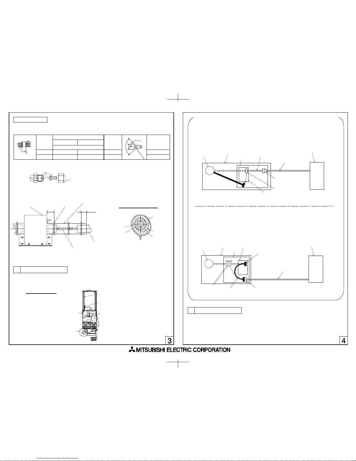
Wiring procedure
Wiring shown below can be applied when the connector board and LEV are connected with relay.
Make sure to complete the work below before turning on the indoor unit
Wiring procedure differs depending on the indoor unit. To remove the electrical box cover when connecting the cables of each
indoor unit, refer to the installation manuals of each indoor unit. Fix the cable together with the on-site wirings (power supply cable,
transmission cable and remote controller cable). Use the fastener5 to bind the cables in the electrical box.
4
Test run
Carry out test run referring to the installation manual enclosed with indoor/outdoor unit.
1. After deciding the installation location, carry out flaring work of liquid pipe and apply thin layer of refrigerant oil (procure locally) to
the flared seat surface
.
2. Connect the field refrigerant piping.
3. Wrap the enclosed pipe cover3 around the liquid pipe connection, pushing it on the outside of External LEV Box1.
4. Secure both ends of pipe cover3 with the enclosed bands4 to make sure it is insulated.
w When flare tools for R22, R407C are used for R410A flaring work, refer to the table above. The size adjustment gauge can be used to secure A measurements.
Apply thin layer of ester oil, ether oil or alkylbenzene oil to the entire flare seat surface.
wDo not apply it to the screws as it ma
y cause loosening of the flare nut.
Make sure to use the flare nut attached to the unit
(Using commercial item may cause breaks).
2-2 Connecting pipes
At factory shipment, the connector for LEV in the indoor unit is connected to the connector (CN60) on indoor controller
board. Replace the connector (CN60) with the white connector of the cable (accessory: 100mm) for External LEV Box1.
Bind the removed lead wire of LEV with fastener5 and place it in the electrical box.
Remove the relay connector in electrical box. Connect the lead wire of the connector (CN60) to the connector of the cable
(Accessory:5300mm) of External LEV Box1. Bind the removed lead wire of LEV with fastener5 and place it in the electrical
box. Remove the cable (accessory: 100mm) since it is unnecessary.
 Loading...