

Mitsubishi MSH-A18WV, MSH-A24WV, MSH-A30WV Service Manual
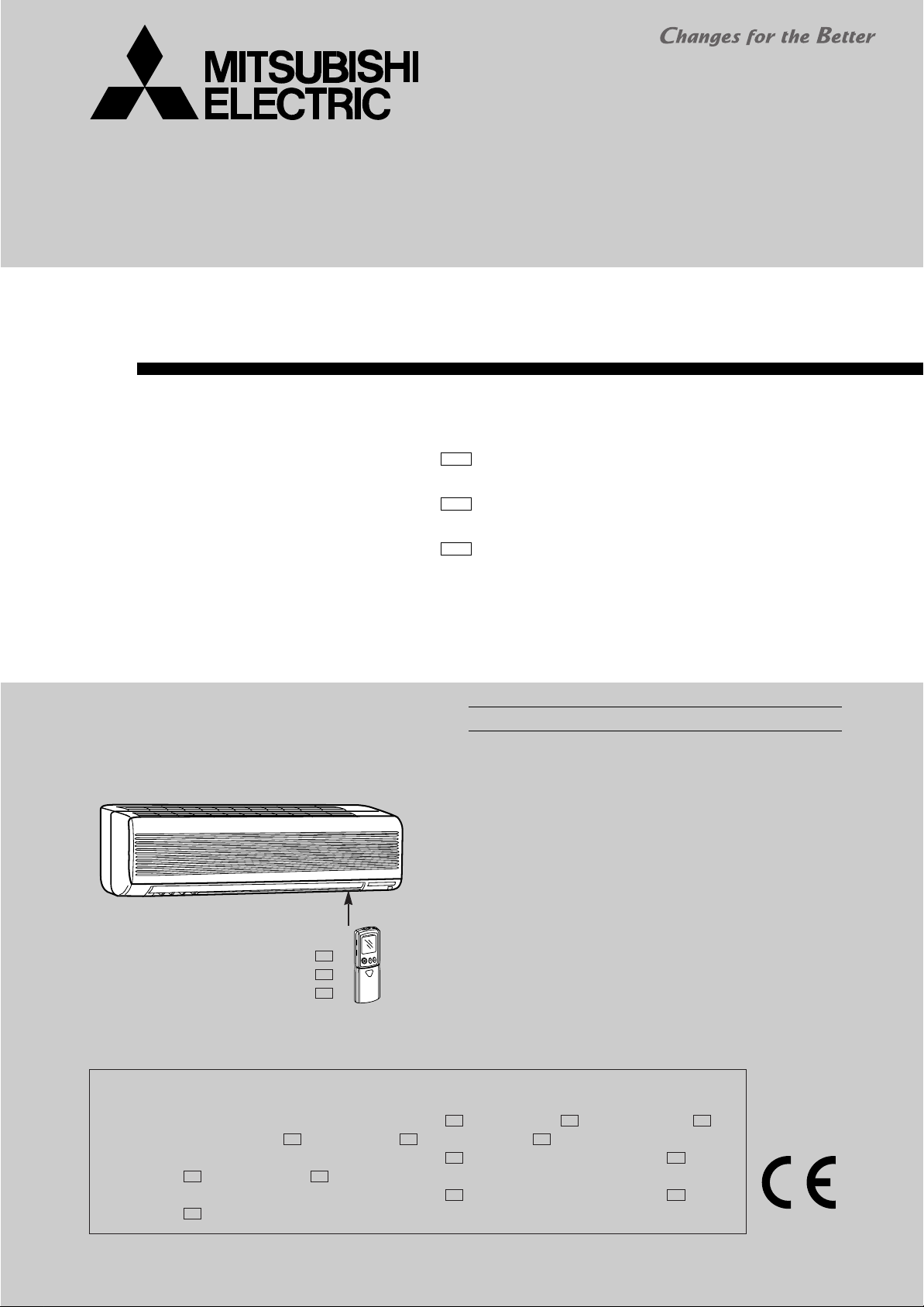
SERVICE MANUAL
SPLIT-TYPE, HEAT PUMP AIR CONDITIONERS
Wireless type
Models
E1
MSH-A18WV MSH-A24WV MSH-A30WV -
(WH)
E1
(WH)
E1
(WH)
CONTENTS
No. OB321
1. TECHNICAL CHANGES ····································2
2. PART NAMES AND FUNCTIONS······················2
3. SPECIFICATION·················································4
4. NOISE CRITERIA CURVES·······························5
5. OUTLINES AND DIMENSIONS·························6
6. WIRING DIAGRAM ············································7
7. REFRIGERANT SYSTEM DIAGRAM················8
8. MICROPROCESSOR CONTROL ······················9
Indication of model name
MSH-A18WV MSH-A24WV MSH-A30WV -
NOTE:
This service manual describes technical data of the indoor unit.
•Refer to the service manual OB322 when MSH-A18WV- , MSH-A24WV- or MSH-A30WV- is
connected with MUH-A18WV- , MUH-A24WV- or MUH-A30WV- .
•Refer to the service manual OB319 when MSH-A18WV- is connected with MXZ-A18WV- ,
MXZ-A26WV- or MXZ-A32WV- as multi system units.
•Refer to the service manual OB319 when MSH-A24WV- is connected with MXZ-A26WV- or
MXZ-A32WV- as multi system units.
E1
E1
E1
E1
E1E1
9. SERVICE FUNCTIONS ····································18
10. TROUBLESHOOTING ······································20
11. DISASSEMBLY INSTRUCTIONS·····················28
12. PARTS LIST······················································30
13. OPTIONAL PARTS ······················BACK COVER
E1E1E1
E1E1E1
E1E1
E1E1
1
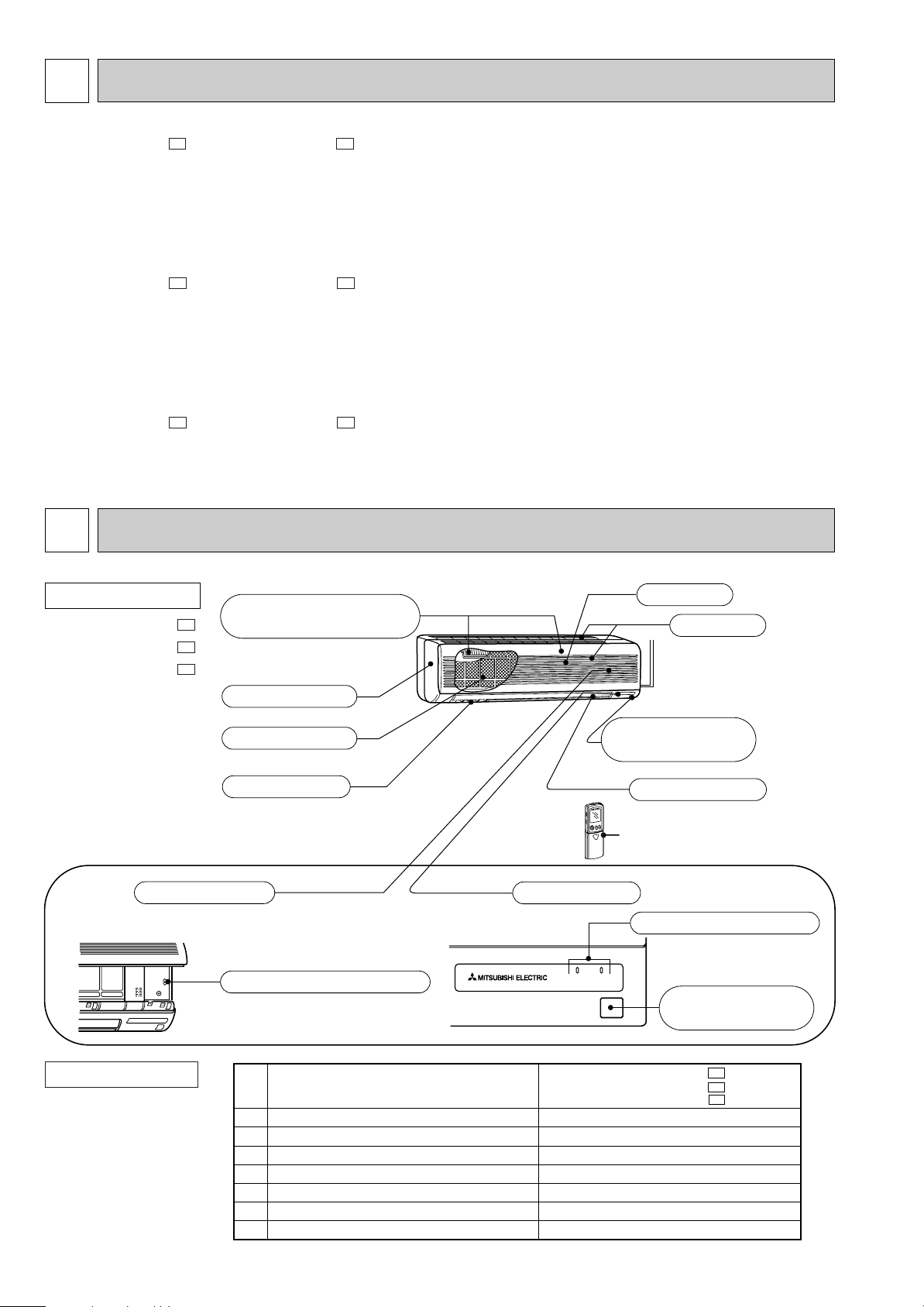
Grille
(When the grille is opened)
Remote controller
Operation section
Display section
Operation Indicator
Emergency operation switch
Operation indicator lamp
Air inlet
Horizontal vane
Remote control
receiving section
Catechin air filter
Air cleaning filter (option)
(White bellows type)
Vertical vanes
Front panel
Remote control
receiving section
1
2
3
4
5
6
7
Installation plate
Installation plate fixing screw 4 o 25 mm
Remote controller holder
Fixing screw for 3 o 3.5 o 1.6 mm (Black)
Battery (AAA) for remote controller
Wireless remote controller
Felt tape (Used for left or left-rear piping)
1
7
1
2
2
1
1
MSH-A18WVMSH-A24WVMSH-A30WV-
E1
E1
E1
TECHNICAL CHANGES
MSH-18RV - ➔MSH-A18WV -
1. Indoor unit model has changed.
2. Rated voltage has changed. (220V-240V ➜ 230V)
3. Remote controller has changed.
•LONG MODE and WIDE MODE have been added.
4. Indoor fan motor has changed.(RA4V27-EF ➜ RC4V32-AA)
5. Indoor heat exchanger has changed.
6. Diameter of connect pipe has changed.(Liquid:[8 ➜ [6.35)
7. Air cleaning filter has changed to catechin air filter.
MSH-24RV - ➔MSH-A24WV -
1. Indoor unit model has changed.
2. Rated voltage has changed. (220V-240V ➜ 230V)
3. Remote controller has changed.
•LONG MODE and WIDE MODE have been added.
4. Indoor fan motor has changed.(RA4V27-EE ➜ RC4V32-AA)
5. Indoor heat exchanger has changed.
6. Diameter of connect pipe has changed.(Liquid:[8 ➜ [6.35)
7. Air cleaning filter has changed to catechin air filter.
MSH-30RV - ➔MSH-A30WV -
1. Diameter of connect pipe has changed.(Gas:[15.88 ➜ [12)
2. Rated voltage has changed. (220V-240V ➜ 230V)
3. Power supply cord has been added.
4. Air cleaning filter has changed to catechin air filter.
2
PART NAMES AND FUNCTIONS
E1E2
E1E2
E1E1
INDOOR UNIT
MSH-A18WV MSH-A24WV MSH-A30WV -
E1
E1
E1
ACCESSORIES
Indoor unit
2
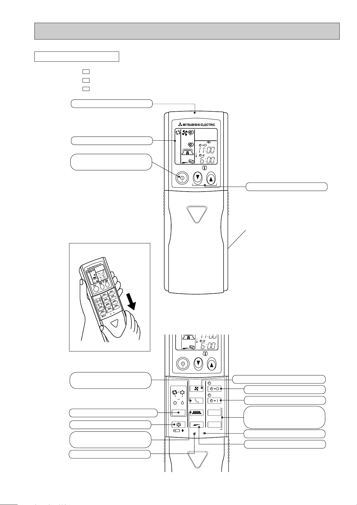
REMOTE CONTROLLER
MSH-A18WV MSH-A24WV MSH-A30WV -
Signal transmitting section
E1
E1
E1
Operation display section
OPERATE /STOP
(ON /OFF)button
ON/OFF
TOO
WARM
PM
AM
TOO
COOL
TEMPERATURE buttons
Indication of remote controller
model is on back.
Open the front lid.
VANE button
(Horizontal vane button)
OPERATION SELECT button
ECONO COOL button
WIDE VANE button
(Vertical vane button)
TOO
ON/OFF
WARM
COOL
DRY
FAN
VANE
WIDE VANE
LONG
RESET CLOCK
I FEEL
HEAT
MODE
ECONO COOL
CLOCK
PM
AM
TOO
COOL
STOP
START
HR.
MIN.
FAN SPEED CONTROL button
OFF-TIMER button
ON-TIMER button
HR. button
MIN. button
(TIME SET button)
CLOCK SET button
LONG button
RESET button
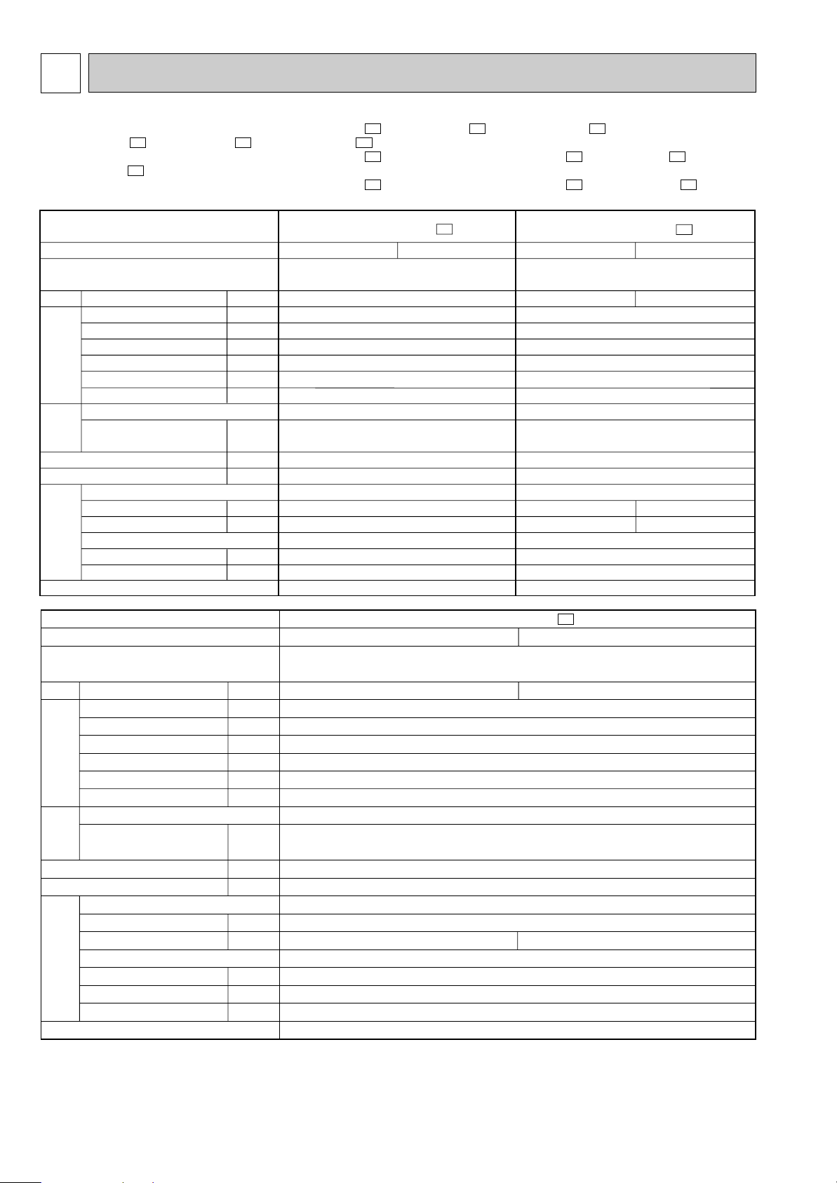
3
3
Indoor model
Function
Power supply
Air flow
(High/Med. /Low )
Power outlet
Running current
Power input
Auxiliary heater
Power factor
Fan motor current
Model
Winding
resistance(at20:)
Dimensions WOHOD
Weight
Air direction
Sound level(High/Med. /Low )
Fan speed(High/Med. /Low )
Fan speed regulator
Thermistor RT11(at25:)
Thermistor RT12(at25:)
Remote controller model
K /h
A
A
W
A(kW)
%
A
"
mm
kg
dB
rpm
k"
k"
MSH-A18WV -
E1
Single phase
230V, 50Hz
768/642 /528
10
0.3
60
—
87
0.30
RC4V32-AA
WHT-BLK 293
BLK-RED 146
1,100O325O227
16
5
42/38 /34
1,070/920 /780
3
10
10
KP0A
Cooling
Heating
MSH-A24WV -
E1
Single phase
230V, 50Hz
10
0.3
60
—
87
0.30
RC4V32-AA
WHT-BLK 293
BLK-RED 146
1,100O325O227
16
5
3
10
10
KP0A
Cooling
768/672 /588
45/41 /37
1,070/960 /850
Heating
768/642 /528
45/40 /34
1,070/920 /780
Electrical
data
Fan
motor
Special
remarks
Capacity
ww
ww
ww ww
ww ww
ww
w
w
w
w
w
w
w
w
ww
Indoor model
Function
Power supply
Air flow
(High/Med. /Low )
Power outlet
Running current
Power input
Auxiliary heater
Power factor
Fan motor current
Model
Winding
resistance(at20:)
Dimensions WOHOD
Weight
Air direction
Sound level(High/Med. /Low )
Fan speed(High/Med. /Low )
Fan speed regulator
Thermistor RT11(at25:)
Thermistor RT12(at25:)
Thermistor RT13(at25:)
Remote controller model
K /h
A
A
W
A(kW)
%
A
"
mm
kg
dB
rpm
k"
k"
k"
MSH-A30WV -
E1
Single phase
230V, 50Hz
10
0.34
69
—
88
0.34
RC4V40-AA
WHT-BLK 138.2
BLK-RED 159.0
1,100O325O227
16
5
47/42 /37
3
10
10
10
KP0A
Cooling
960/822 /684
1,280/1,130 /970
Heating
960/834 /732
1,280/1,150 /1,020
Electrical
data
Fan
motor
Special
remarks
Capacity
ww
w
w
w
w
ww
w
w
w
w
w
w
w
w
SPECIFICATION
•Refer to the service manual OB322 when MSH-A18WV- , MSH-A24WV- or MSH-A30WV- is connected with
MUH-A18WV- , MUH-A24WV- or MUH-A30WV- .
E1E1E1
•Refer to the service manual OB319 when MSH-A18WV- is connected with MXZ-A18WV- , MXZ-A26WV- or
MXZ-A32WV- as multi system units.
E1
•Refer to the service manual OB319 when MSH-A24WV- is connected with MXZ-A26WV- or MXZ-A32WV- as multi
E1E1E1
E1E1E1
E1E1E1
system units.
NOTE: Test conditions are based on JIS C 9612.
Cooling : Indoor DB27°C WB19°C Heating : Indoor DB20°C WB 15.5°C
Indoor-Outdoor piping length 5m
w Reference value
Outdoor DB35°C WB(24°C) Outdoor DB 7°C WB 6°C
4
4
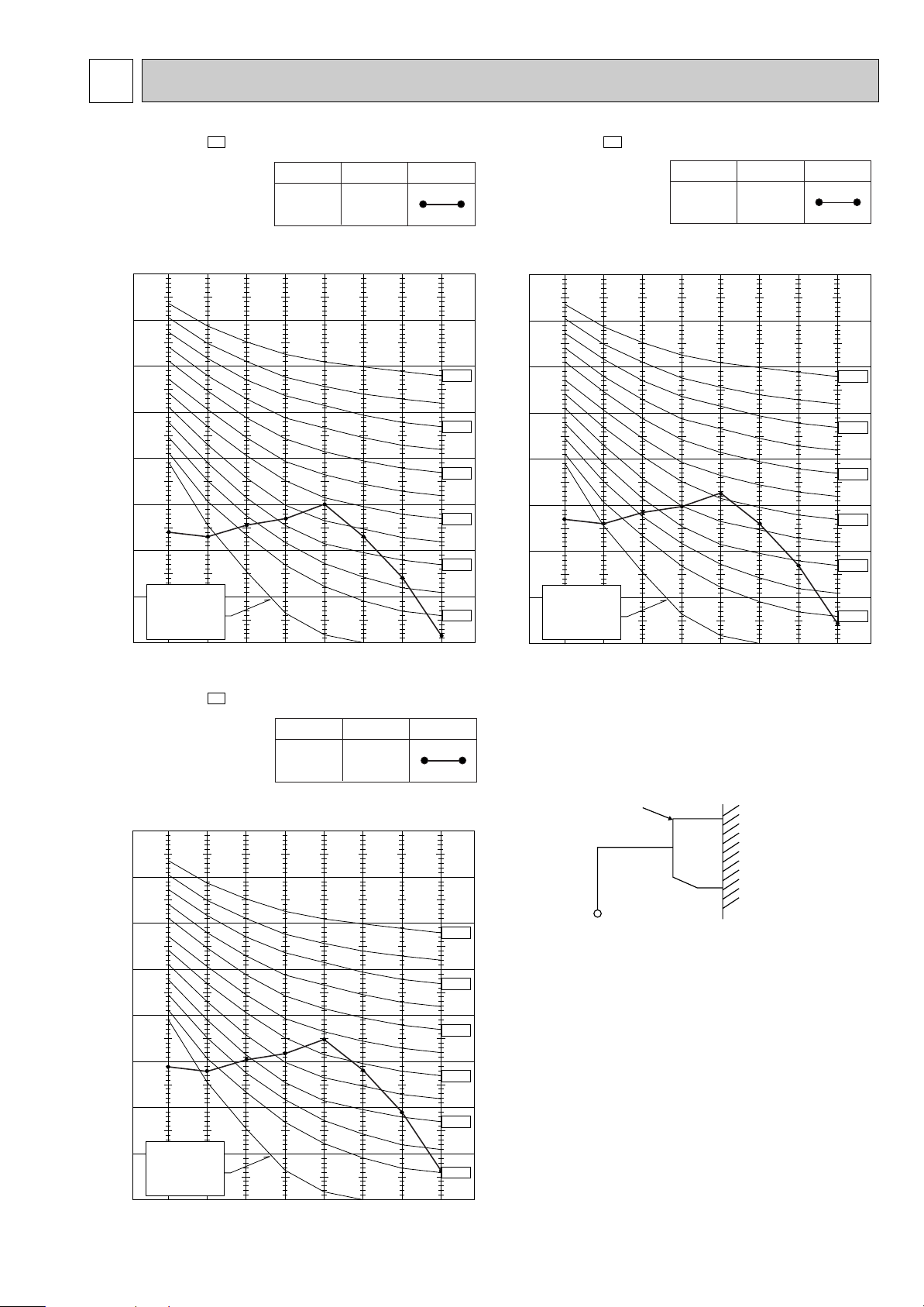
90
80
70
60
50
40
30
20
10
63 125 250 500 1000 2000 4000 8000
OCTAVE BAND SOUND PRESSURE LEVEL, dB re 0.0002 MICRO BAR
BAND CENTER FREQUENCIES, Hz
APPROXIMATE
THRESHOLD OF
HEARING FOR
CONTINUOUS
NOISE
NC-60
NC-50
NC-40
NC-30
NC-20
NC-70
Test conditions,
Cooling : Dry-bulb temperature 27: Wet-bulb temperature 19:
47
SPL(dB(A)) LINE
High
FAN SPEED
Heating : Dry-bulb temperature 20: Wet-bulb temperature 15.5:
NOISE CRITERIA CURVES
MSH-A18WV-
E1
FAN SPEED
High
SPL(dB(A)) LINE
42
Test conditions,
Cooling : Dry-bulb temperature 27: Wet-bulb temperature 19:
Heating : Dry-bulb temperature 20: Wet-bulb temperature 15.5:
90
80
70
NC-70
60
NC-60
50
NC-50
40
NC-40
30
NC-30
MSH-A24WV-
E1
FAN SPEED
High
SPL(dB(A)) LINE
45
Test conditions,
Cooling : Dry-bulb temperature 27: Wet-bulb temperature 19:
Heating : Dry-bulb temperature 20: Wet-bulb temperature 15.5:
90
80
70
NC-70
60
NC-60
50
NC-50
40
NC-40
30
NC-30
APPROXIMATE
20
THRESHOLD OF
HEARING FOR
CONTINUOUS
OCTAVE BAND SOUND PRESSURE LEVEL, dB re 0.0002 MICRO BAR
NOISE
10
63 125 250 500 1000 2000 4000 8000
BAND CENTER FREQUENCIES, Hz
MSH-A30WV-
E1
NC-20
APPROXIMATE
20
THRESHOLD OF
HEARING FOR
CONTINUOUS
OCTAVE BAND SOUND PRESSURE LEVEL, dB re 0.0002 MICRO BAR
NOISE
10
63 125 250 500 1000 2000 4000 8000
BAND CENTER FREQUENCIES, Hz
INDOORUNIT
WALL
1m
0.8m
MICROPHONE
NC-20
5
5
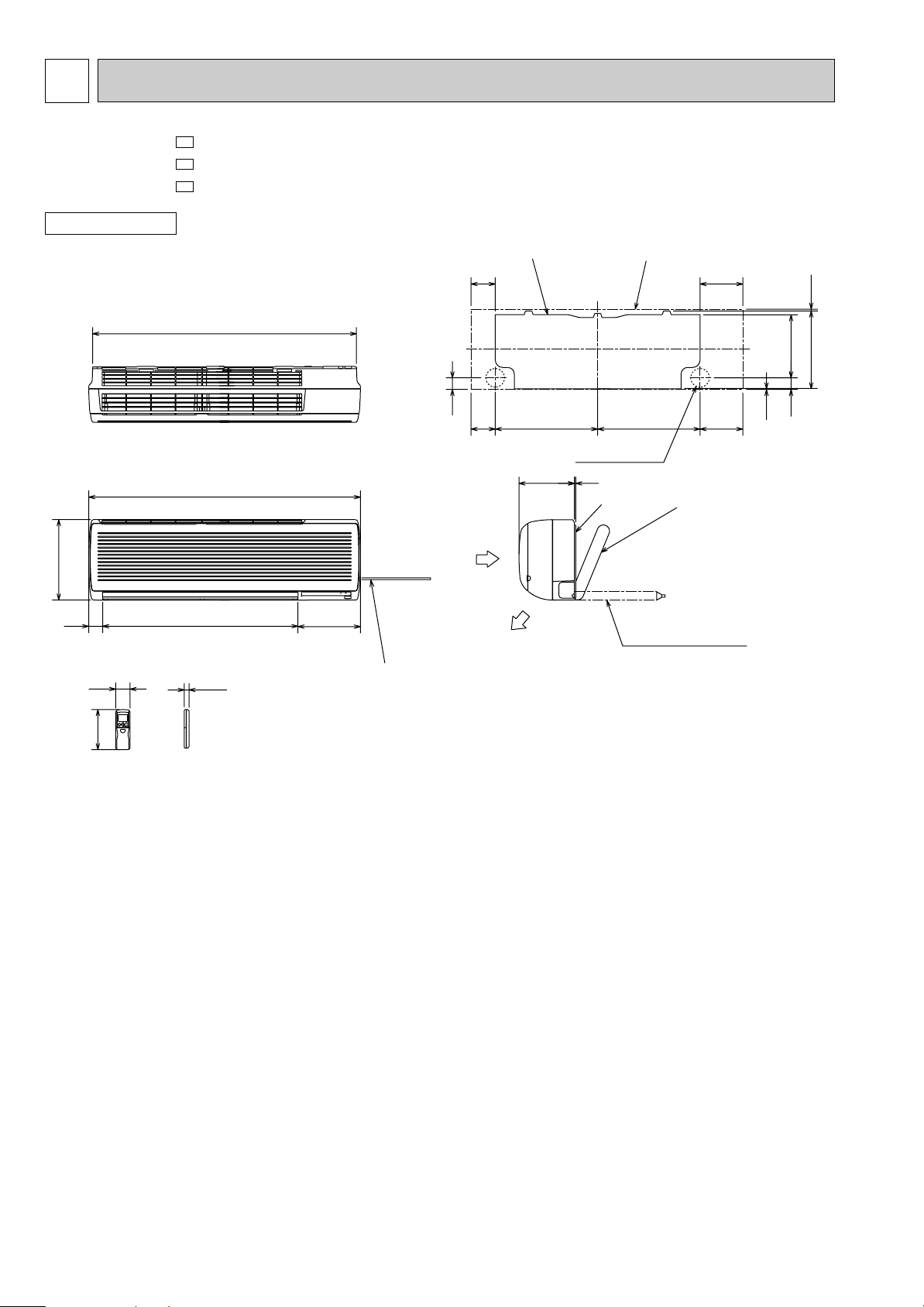
162
19
58
47
7.5315
255.547
2.5
98 173
98 173414.5 414.5
5225
253
791
56
1068
1100
325
Air out
Air in
Insulation [ 28
Drain hose [ 16
(Connected part O.D)
{
Liquid line [ 6.35-0.5m
Gas line [ 12-0.43m
Insulation [ 50 O.D
[ 32 I.D
Installation plate
Wall hole [ 75
Wireless remote controller
Installation plate
Indoor unit
{
Liquid line [ 9.52-0.5m
Gas line [ 12-0.43m
Insulation [ 50 O.D
[ 32 I.D
for MSH-A18/A24WV
for MSH-A30WV
Power supply cord
Lead to right 2.0m
Lead to left 1.0m
OUTLINES AND DIMENSIONS
MSH-A18WV MSH-A24WV MSH-A30WV -
INDOOR UNIT
E1
E1
E1
Unit: mm
6
6
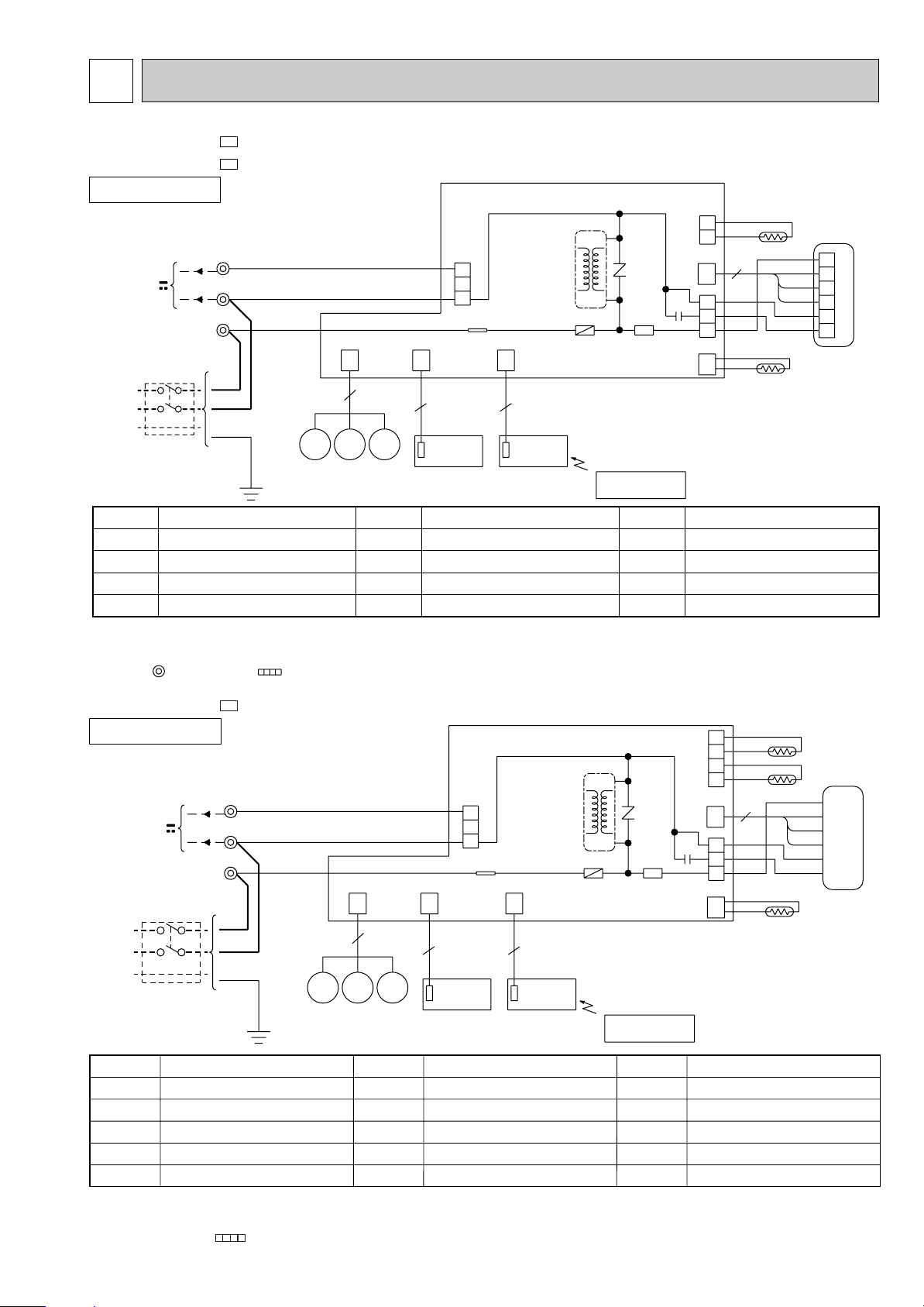
WIRING DIAGRAM
MSH-A18WV MSH-A24WV -
INDOOR UNIT
TO OUTDOOR
UNIT
CONNECTING
12V
POWER
SUPPLY
CORD
~/N 230V
50Hz
PE
CIRCUIT
BREAKER
SYMBOL
C11
F11
HIC1
MF
NOTES:
INDOOR FAN CAPACITOR
FUSE (3.15A)
DC/DC CONVERTER
INDOOR FAN MOTOR (INNER FUSE)
1.About the outdoor side electric wiring refer to the outdoor unit electric wiring diagram for servicing.
2.Use copper conductors only. (For field wiring)
3.Symbols below indicate.
: Terminal block
E1
E1
MODELS WIRING DIAGRAM
TB
3
N
L
RED
BLU
BRN
CN
151
BRN
MV2
15
MV1
BLU
MV2
GRN/YLW
NAME
SYMBOL
MV1
MV2
NR11
RT11
: Connector
HIC1
CN201
CN
102
3
DISPLAY
P.C.BOARD
3
2
1
TAB12
TRANS
F11
ELECTRONIC CONTROL
CN
101
P.C. BOARD
3
RECEIVER
P.C.BOARD
NAME
NR11
SR141
REMOTE
CONTROLLER
SYMBOL
VANE MOTOR (HORIZONTAL)
VANE MOTOR (VERTICAL)
SR141
VARISTOR
ROOM TEMPERATURE THERMISTOR
RT12
TB
C11
2
1
CN112
CN
121
1
3
4
3
RT12
BLK
GRY
YLW
BRN
WHT
RED
CN211
CN
111
RT11
NAME
INDOOR COIL THERMISTOR
SOLID STATE RELAY
TERMINAL BLOCK
VG79J878H02
1
2
3
MF
4
5
6
MSH-A30WV -
E1
MODEL WIRING DIAGRAM
INDOOR UNIT
TO OUTDOOR
UNIT
CONNECTING
12V
POWER
SUPPLY
CORD
~/N 230V
50Hz
PE
CIRCUIT
BREAKER
TB
3
N
L
BRN
BLU
RED
BLU
BRN
MV2
CN
151
MV2
15
MV1
CN201
CN
102
DISPLAY
P.C.BOARD
3
2
1
TAB12
ELECTRONIC CONTROL
CN
101
P.C. BOARD
33
RECEIVER
P.C.BOARD
GRN/YLW
SYMBOL
C11
F11
HIC1
MF
MV1
NOTE:1. About the outdoor side electric wiring refer to the outdoor unit electric wiring diagram for servicing.
INDOOR FAN CAPACITOR
FUSE(3.15A)
DC/DC CONVERTER
INDOOR FAN MOTOR(INNER PROTECTOR)
VANE MOTOR(HORIZONTAL)
2. Use copper conductors only. (For field wiring)
3. Symbols below indicate.
/: Terminal block, : Connector
NAME
SYMBOL
MV2
NR11
RT11
RT12
RT13
NAME NAME
VANE MOTOR(VERTICAL)
VARISTOR
ROOM TEMPERATURE THERMIST OR
INDOOR COIL THERMISTOR (MAIN)
INDOOR COIL THERMISTOR (SUB)
7
HIC1
TRANS
F11
NR11
C11
SR141
REMOTE
CONTROLLER
SYMBOL
SR141
TB
4
3
2
1
CN112
CN
121
1
3
4
3
RT13
RT12
BLK
GRY
YLW
BRN
WHT
RED
CN211
CN
111
RT11
SOLID STATE RELAY
TERMINAL BLOCK
SG79J880H02
MF
7
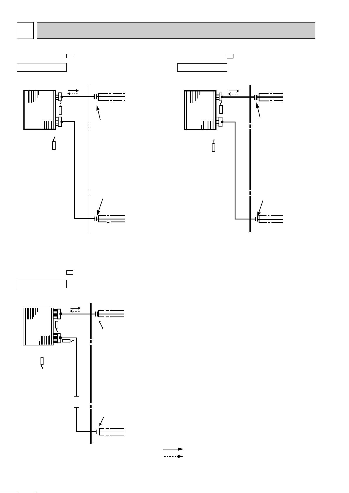
REFRIGERANT SYSTEM DIAGRAM
MSH-A18WV -
INDOOR UNIT
Indoor
heat
exchanger
Room temperature
thermistor
RT11
E1
Indoor coil
thermistor
RT12
Distributor
Refrigerant pipe [12.7
(with heat insulator)
Flared connection
Flared connection
MSH-A24WV -
INDOOR UNIT
Indoor
heat
exchanger
Room temperature
thermistor
RT11
E1
Indoor coil
thermistor
RT12
Distributor
Unit:mm
Refrigerant pipe [15.88
(with heat insulator)
Flared connection
Flared connection
MSH-A30WV -
INDOOR UNIT
Indoor
heat
exchanger
Room temperature
thermistor
RT11
Indoor coil
thermistor
RT12(main)
Indoor coil
thermistor
RT13(sub)
Strainer
#50
Refrigerant pipe[6.35
(with heat insulator)
E1
Refrigerant pipe [15.88
(with heat insulator)
Flared connection
Flared connection
Refrigerant pipe [6.35
(with heat insulator)
Refrigerant pipe [9.52
(with heat insulator)
Refrigerant flow in cooling
Refrigerant flow in heating
8
8
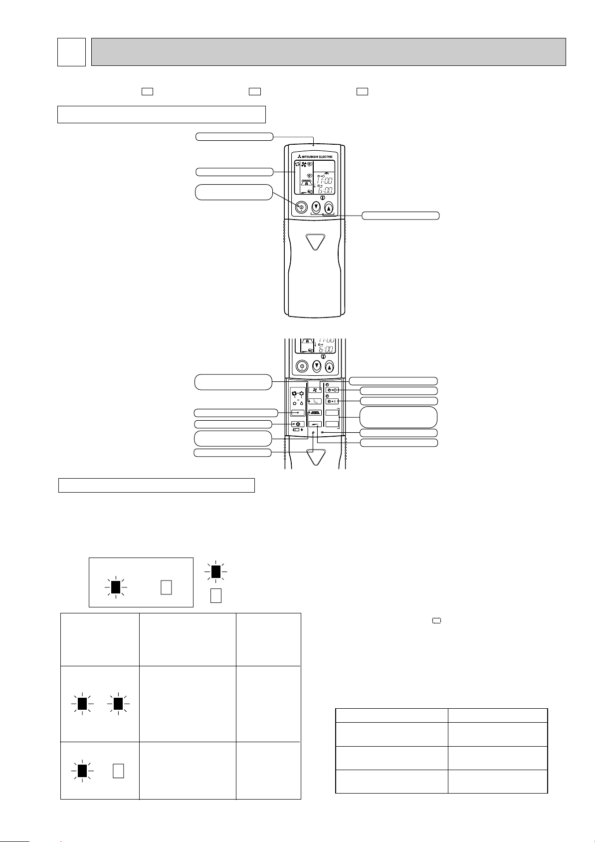
lighted
not lighted
Approx. 2 :
or more
Difference
between target
temperature
and room
temperature
Approx. 2 :
or less
This shows that the
air conditioner is
operating to reach
the target temperature.
Please wait until the
target temperature is
obtained.
This shows that the
room temperature is
approaching the
target temperature.
Operation stateIndication
Operation Indicator
Operation Indicator lamp
The operation indicator at the right side of the indoor
unit indicates the operation state.
INDOOR UNIT DISPLAY SECTION
• The following indication applies regardless of
shape of the indicator.
MICROPROCESSOR CONTROL
MSH-A18WV - MSH-A24WV - MSH-A30WV -
WIRELESS REMOTE CONTROLLER
Signal transmitting section
Operation display section
OPERATE /STOP
(ON /OFF)button
VANE button
(Horizontal vane button)
OPERATION SELECT button
ECONO COOL button
WIDE VANE button
(Vertical vane button)
RESET button
I FEEL
HEAT
MODE
ECONO COOL
ON/OFF
ON/OFF
COOL
DRY
TOO
WARM
CLOCK
TOO
WARM
FAN
VANE
WIDE VANE
LONG
RESET CLOCK
PM
AM
TOO
COOL
PM
AM
TOO
COOL
STOP
START
HR.
MIN.
E1E1E1
TEMPERATURE buttons
FAN SPEED CONTROL button
OFF-TIMER button
ON-TIMER button
HR. button
MIN. button
(TIME SET button)
CLOCK SET button
LONG button
Once the operation mode are set, the same operation mode
can be repeated by simply turning the OPERATE/STOP
(ON/OFF) button ON.
Indoor unit receives the signal with a beep tone.
When the system turns off, 3-minute time delay will operate to
protect system from overload and compressor will not restart
for 3 minutes.
8-1. “I FEEL CONTROL” ( ) OPERATION
(1) Press OPERATE/STOP (ON/OFF) button on the remote
controller. OPERATION INDICATOR lamp of the indoor
unit turns on with a beep tone.
(2) Select “I FEEL CONTROL” mode with the OPERATION
SELECT button.
(3) The operation mode is determined by the room tempera-
ture at start-up of the operation.
Initial room temperature
25: or more
23:to 25:
less than 23:
9
Mode
COOL mode of
"I FEEL CONTROL"
DRY mode of
"I FEEL CONTROL"
HEAT mode of
"I FEEL CONTROL"
• Once the mode is fixed, the mode does not change by room temperature afterwards.
Model
COOL mode of
"I FEEL CONTROL"
DRY mode of
"I FEEL CONTROL"
HEAT mode of
"I FEEL CONTROL"
Initial room temperature Initial set temperature
26:
26: or more
25: to 26:
less than 23:
23: to 25:
24:
Initial room temperature
minus 2:
Initial room temperature
minus 2:
❈1
TOO
COOL
TOO
WARM
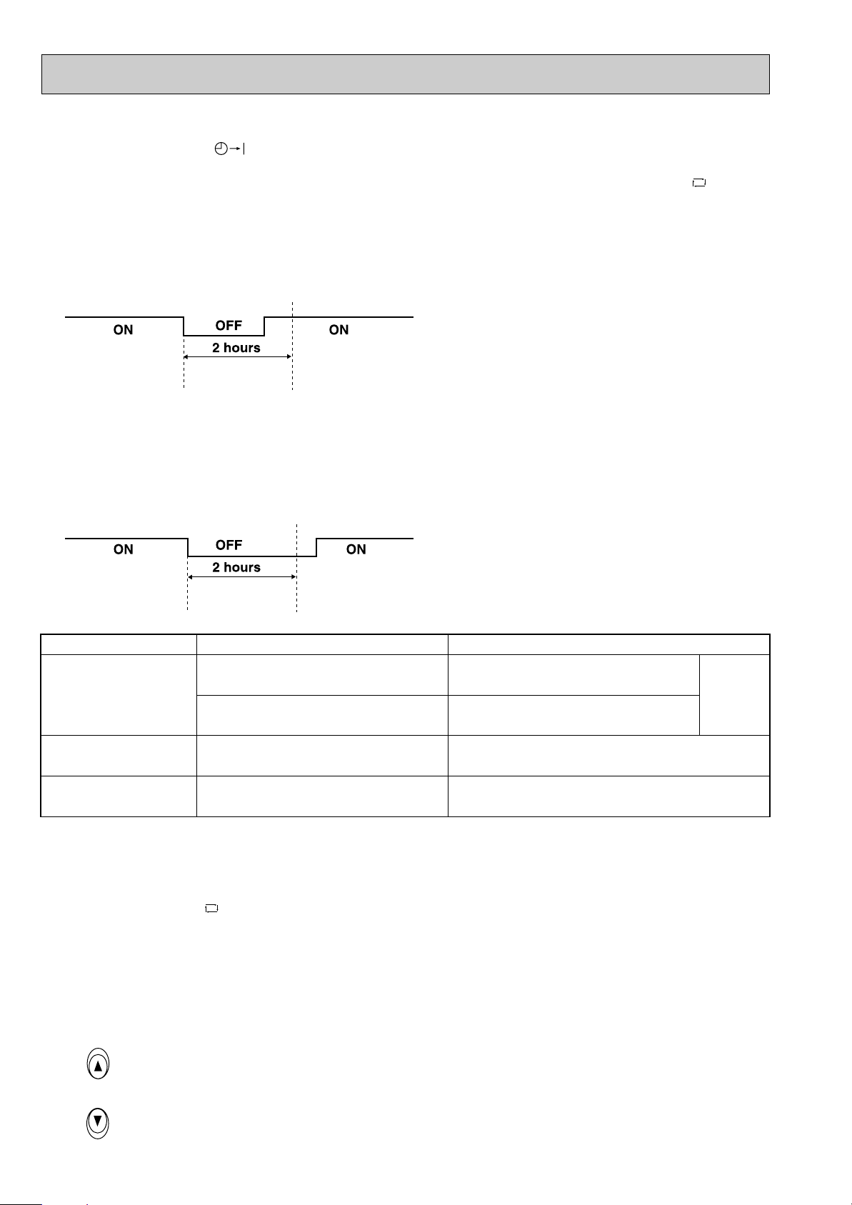
• Under the ON-TIMER ( ) operation, mode is determined according to the room temperature at the set time the
operation starts.
• When the system is stopped on the remote controller, and restarted within 2 hours in “I FEEL CONTROL” ( ) mode,
the system operates in previous mode automatically regardless of the room temperature.
Operation time chart
Example
Previous operation
COOL mode of
“I FEEL CONTROL”
Restart
COOL mode of
“I FEEL CONTROL”
or COOL mode
When the system is restarted after 2 hours and more, the operation mode is determined by the room temperature at
start-up of the operation.
Operation time chart
Example
Restart
COOL or DRY or
Previous operation
COOL mode of
“I FEEL CONTROL”
or COOL mode
HEAT mode of “I FEEL
CONTROL” that determined by room temperature at start-up of
the operation.
(4) The initial set temperature is decided by the initial room temperature.
❈1 When the system is restarted with the remote controller, the system operates with the previous set temperature regard-
less of room temperature at restart.
The set temperature is calculated by the previous set temperature.
(5) TEMPERATURE buttons
In “I FEEL CONTROL” ( ) mode, set temperature is decided by the microprocessor based on the room temperature.
In addition, set temperature can be controlled by TOO WARM or TOO COOL buttons when you feel too cool or too warm.
Each time the TOO WARM or TOO COOL button is pressed, the indoor unit receives the signal and emits a beep tone.
• Fuzzy control
When the TOO COOL or TOO WARM button is pressed, the microprocessor changes the set temperature, considering
the room temperature, the frequency of pressing TOO COOL or TOO WARM button and the user’s preference to heat or
cool. So this is called “Fuzzy control”, and works only in “I FEEL CONTROL” mode.
In DRY mode of “I FEEL CONTROL”, the set temperature doesn’t change.
…
…
To raise the set temperature 1~2 degrees(°C)
To lower the set temperature 1~2 degrees(°C)
10
 Loading...