

Mitsubishi Electric GENERAL PURPOSE AC SERVO MR-E- A/AG, MR-E-A, MR-E-AG Instruction Manual

General-Purpose AC Servo
MODEL
MR-E- A/AG
INSTRUCTION MANUAL
B
A - 1
Safety Instructions
(Always read these instructions before using the equipment.)
Do not attempt to install, oper ate, mainta in or inspect the s ervo amplif ier and servo m otor until you hav e read
through this I nstruction M anual, Insta llation guide, Servo motor Instruction Manual a nd appende d docum ents
carefully and can use the equipment corr ect l y. D o not use the ser vo amplifier and servo motor un ti l you have a
full knowledge of the equipment, safety information and instructions.
In this Instruction Manual, the safety instruction levels are classified into "WARNING" and "CAUTION".
WARNING
Indicates that incorrect handling may cause hazardous conditions,
resulting in death or severe injury.
CAUTION
Indicates that incorrect handling may cause hazardous conditions,
resulting in medium or slight injury to personnel or may cause physical
damage.
Note that the CAUTION level may lead to a serious consequence according to conditions. Please follow the
instructions of both levels because they are important to personnel safety.
What must not be done and what must be done are indicated by the following diagrammatic symbols:
: Indicates what must not be done. For example, "No Fire" is indicated by
.
: Indicates what must be do ne . Fo r exa mple , gr ou nd ing i s in di cat ed by
.
In this Instruction Manual, instructions at a lower level than the above, instructions for other functions, and so
on are classified into "POINT".
After reading this installation guide, always keep it accessible to the operator.
A - 2
1. To prevent electric shock, note the following:
WARNING
Before wiring or inspection, switch power off and wait for more than 10 minutes. Then, confirm the voltage
is safe with voltage tester. Otherwise, you may get an electric shock.
Connect the serv o a mpl i fier and se rvo mot o r to grou nd .
Any person who is involved in wiring and inspection should be fully competent to do the work.
Do not attempt to wire the servo amplifier and servo motor until they have been installed. Otherwise, you
may get an electric shock.
Operate the switches with dry hand to prevent an electric shock.
The cables should not be damaged, st ressed, loaded, or pin ched. Othe rwise, y ou may get an ele ctric shock.
2. To prevent fire, note the following:
CAUTION
Do not install the servo amplifier, servo motor and regenerative brake resistor on or near combustibles.
Otherwise a fire may cause.
When the servo amplifier has become faulty, switch off the main servo amplifier power side. Continuous
flow of a large current may cause a fire.
When a regenerative brake resistor is used, use an alarm signal to switch main power off. Otherwise, a
regenerative brake transistor fault or the like may overheat the regenerative brake resistor, causing a fire.
3. To prevent injury, note the follow
CAUTION
Only the voltage specified in the Instruction Manual should be applied to each terminal, Otherwise, a
burst, damage, etc. may occur.
Connect the terminals correctly to prevent a burst, damage, etc.
Ensure that polarity ( , ) is correct. Otherwise, a burst, damage, etc. may occur.
During power-on or for some time after power-off, do not touch or close a parts (cable etc.) to the servo
amplifier heat sink, regenerative brake resistor, servo motor, etc. Their temperatures may be high and you
may get burnt or a parts may damaged.
During operation, never touch the rotating parts of the servo motor. Doing so can cause injury.
A - 3
4. Additional instructions
The following instructions should also be fully noted. Incorrect handling may cause a fault, injury, electric
shock, etc.
(1) Transportation and installation
CAUTION
Transport the products correctly according to their weights.
Stacking in excess of the specified number of products is not allowed.
Do not carry the servo motor by the cables, shaft or encoder.
Do not hold the front cover to transport the servo amplifier. The servo amplifier may drop.
Install the servo amplifier in a load-bearing place in accordance with the Instruction Manual.
Do not climb or stand on servo equipment. Do not put heavy objects on equipment.
The servo amplifier and servo motor must be installed in the specified direction.
Leave specified clearances between the servo amplifier and control enclosure walls or other equipment.
Do not install or operate the servo amplifier and servo motor which has been damaged or has any parts
missing.
Provide adequate protection to prevent screws and other conductive matter, oil and other combustible
matter from entering the servo amplifier.
Do not drop or strike servo amplifier or servo motor. Isolate from all impact loads.
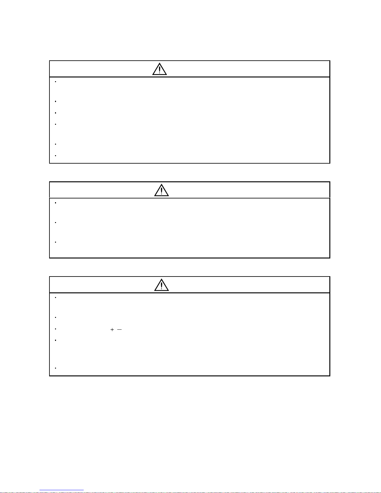
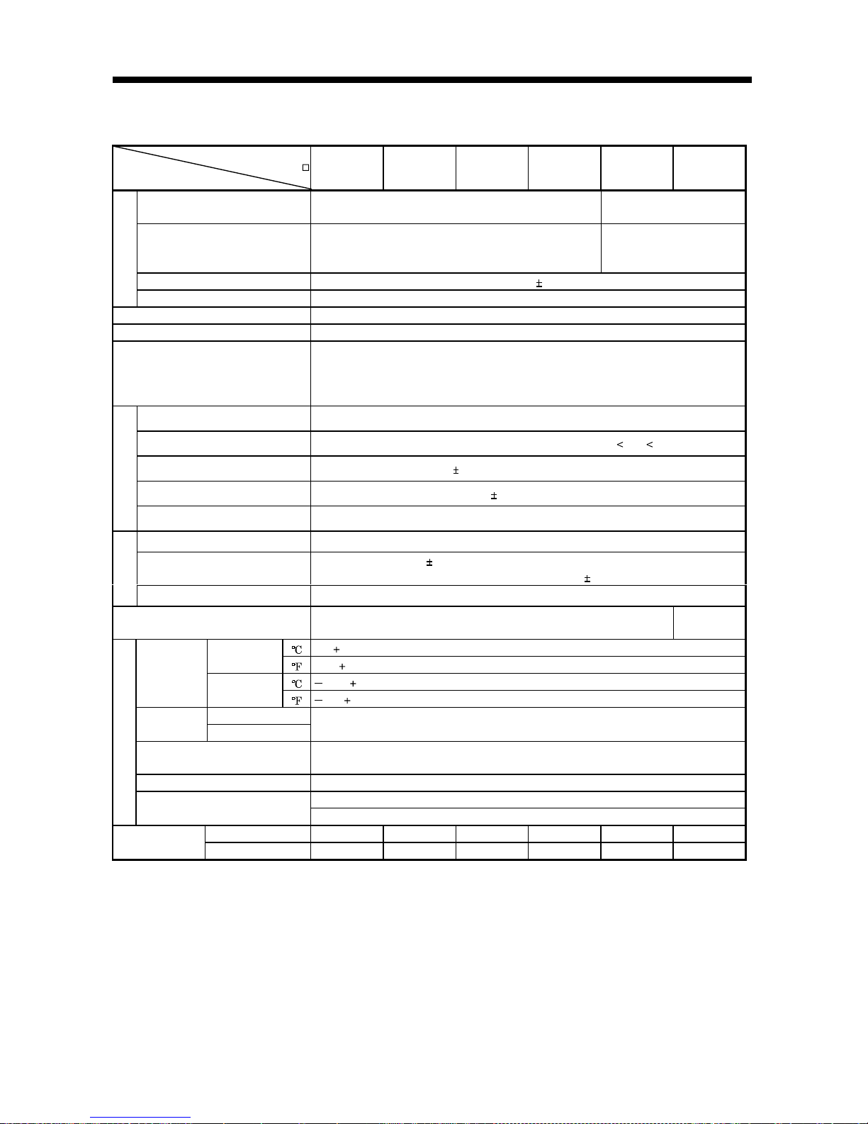
Use the servo amplifier and servo motor under the following environmental conditions:
Conditions
Environment
Servo amplifier Servo motor
[ ]0 to 55 (non-freezing) 0 to 40 (non-freezing)
Ambient
temperature
[
] 32 to 131 (non-freezing) 32 to 104 (non-freezing)
Ambient humidity 90%RH or less (non-condensing) 80%RH or less (non-condensing)
[ ] 20 to 65 (non-freezing) 15 to 70 (non-freezing)
Storage
temperature
[
] 4 to 149 (non-freezing) 5 to 158 (non-freezing)
Storage humidity 90%RH or less (non-condensing)
Ambience Indoors (no direct sunlight) Free from corrosive gas, flammable gas, oil mist, dust and dirt
Altitude Max. 1000m (3280 ft) above sea level
HC-KFE Series X Y : 49
HC-SFE52 to 152 X Y : 24.5
[m/s2] 5.9 or less
HC-SFE202
X : 24.5
Y : 49
HC-KFE Series X Y : 161
HC-SFE52 to 152 X Y : 80
(Note)
Vibration
[ft/s
2
] 19.4 or less
HC-SFE202
X : 80
Y : 161
Note: Except the servo motor with reduction gear.
Securely attach the servo motor to the machine. If attach insecurely, the servo motor may come off during
operation.
The servo motor with reduction gear must be installed in the specified direction to prevent oil leakage.
Take safety measures, e.g. provide covers, to prevent accidental access to the rotating parts of the servo
motor during operation.
Never hit the servo motor or shaft, especially when coupling the servo motor to the machine. The encoder
may become faulty.
Do not subject the servo motor shaft to more than the permissible load. Otherwise, the shaft may break.
When the equipment has been stored for an extended period of time, consult Mitsubishi.
A - 4
(2) Wiring
CAUTION
Wire the equipment correctly and securely. Otherwise, the servo motor may misoperate.
Do not install a power capacitor, surge absorber or radio noise filter (FR-BIF option) between the servo
motor and servo amplifier.
Connect the output terminals (U, V, W) correctly. Otherwise, the servo motor will operate improperly.
Do not connect AC power directly to the servo motor. Otherwise, a fault may occur.
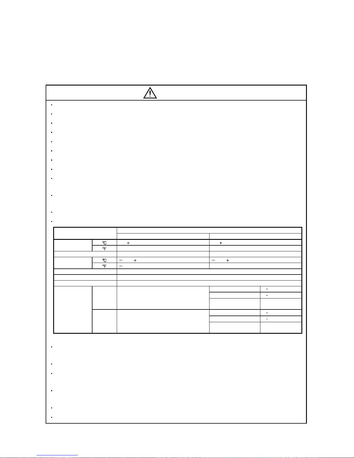
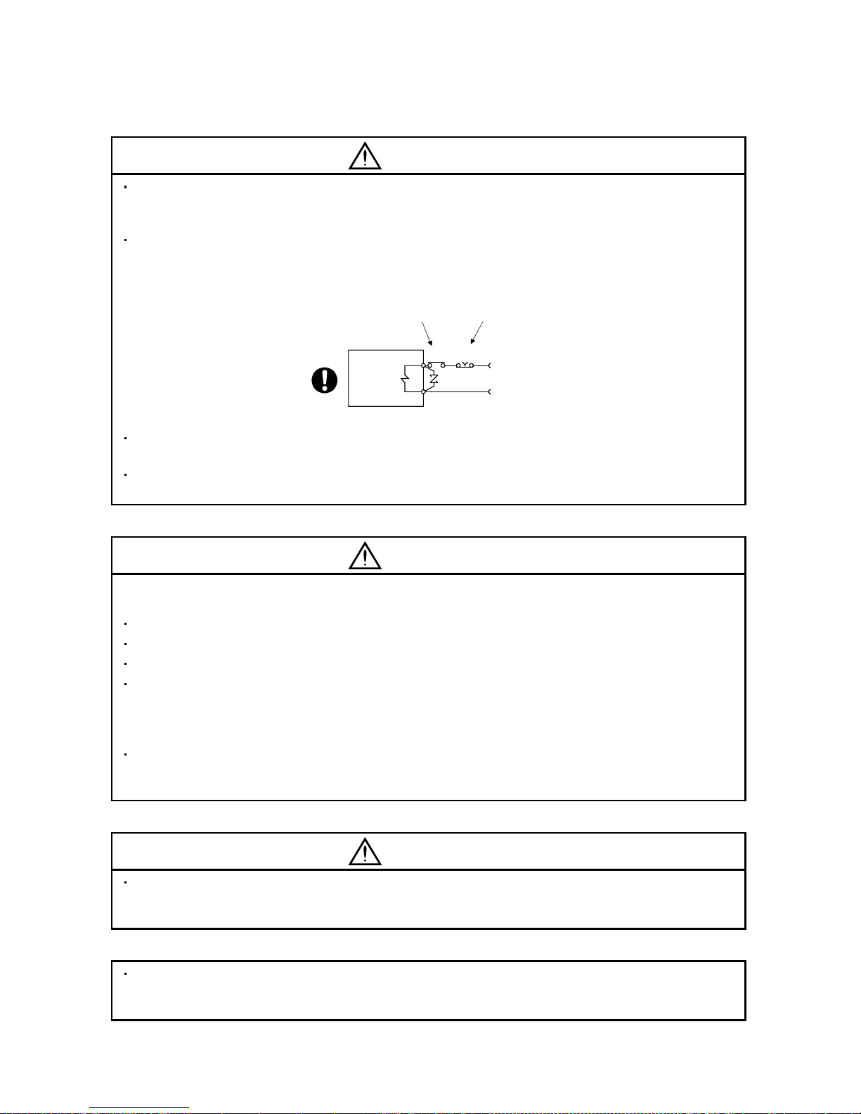
The surge absorbing dio de in stal le d on th e DC ou t put si gna l rel ay must be wired in the speci fie d di re ctio n .
Otherwise, the emergency stop and other protective circuits may not operate.
External
24VDC
RA
Servo
Amplifier
Control output
signal
Servo
Amplifier
RA
Control output
signal
External
24VDC
(3) Test run adjustment
CAUTION
Before operation, check the parameter settings. Improper settings may cause some machines to perform
unexpected operation.
The parameter settings must not be changed excessively. Operation will be insatiable.
(4) Usage
CAUTION
Provide an extern al emergenc y stop c ircuit to ensure that oper ation ca n be sto pped and power s witched
off immediately.
Any person who is involved in disassembly and repair should be fully competent to do the work.
Before resettin g an alarm , make sure th at the run s ignal i s of f to pre vent an accid ent. A s udde n rest art is
made if an alarm is reset with the run signal on.
Do not modify the equipment.
Use a noise filter, etc. to minim i ze the inf lue nce of e lectromagnetic int erf erenc e, which m a y be c aus ed b y
electronic equipment used near the servo amplifier.
Use the servo amplifier with the specified servo motor.
The electromagnetic brake on the servo motor is designed to hold the motor shaft and should not be used
for ordinary braking.
For such reas ons as servic e life and mec hanical struc ture (e.g. wher e a ballscrew and the s ervo motor
are coupled via a tim ing belt), the electrom agnetic brak e may not hol d the m otor shaf t. To ensur e safet y,
install a stoppe r on the mach in e side .
A - 5
(5) Corrective actions
CAUTION
When it is assu med that a ha zardous con dition ma y take place at t he occur due to a power f ailure or a
product fault, use a servo motor with electromagnetic brake or an external brake mechanism for the
purpose of prev en ti on .
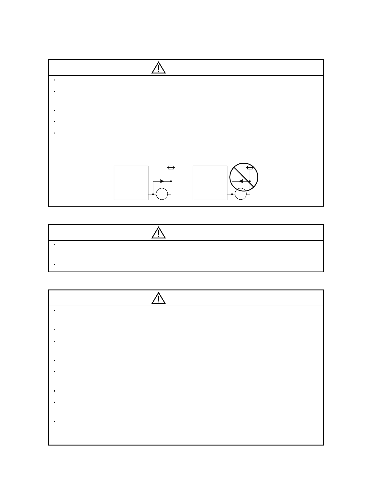
Configure the e lectromagnet ic brake circu it so that it is activated not only by the servo ampl ifier signa ls
but also by an external emergency stop signal (EMG).
EMGRA
24VDC
Contacts must be open when
servo-on signal is off, when an
alarm (trouble) is present and when
an electromagnetic brake signal.
Electromagnetic brake
Servo motor
Circuit must be
opened during
emergency stop signal.
When any alarm has occurred, eliminate its cause, ensure safety, and deactivate the alarm before
restarting operation.
When power is restor ed after an insta ntaneous po wer failure, keep awa y from the m achine beca use the
machine may be restarted suddenly (design the machine so that it is secured against hazard if restarted).
(6) Storage for serv o mo tor
CAUTION
Note the follow ing points whe n storing th e servo motor for an exten ded period of time (guide line: three or
more months).
Always store the servo motor indoors in a clean and dry place.
If it is stored in a dusty or damp place, make adequate provision, e.g. cover the whole product.
If the insulation resistance of the winding decreases, reexamine the storage method.
Though the servo m otor is rust-proofed befor e shipment using paint or rust preven tion oil, rust ma y be
produced depending on the storage conditions or storage period.
If the servo motor is to be stored for longer than six months, apply rust prevention oil again especially to
the machined surfaces of the shaft, etc.
Before using the prod uct after stor age for an extend ed pe ri od of tim e, h and-tur n the m otor out put sh aft t o
confirm that not hing is wrong with the ser vo motor. (When the servo m otor is equipped with a br ake,
make the above check after releasing the brake with the brake power supply.)
(7) Maintenance, inspection and parts replacement
CAUTION
With age, the electrolytic capacitor will deteriorate. To prevent a secondary accident due to a fault, it is
recommended to replace the electrolytic capacitor every 10 years when used in general environment.
Please consult our sales representative.
(8) General instructi o n
To illustrate details, the equipment in the diagrams of this Instruction Manual may have been drawn
without covers and safety guards. When the equipment is operated, the covers and safety guards must be
installed as specified. Operation must be performed in accordance with this Instruction Manual.

A - 6
About processing of waste
When you discard servo amplifier, a battery (primary battery), and other option articles, please follow the law of
each country (area).
FOR MAXIMUM SAFETY
This product is not designed or manufactured to be used in equipment or systems in situations that can
affect or enda nge r hu man li fe .
When considering this product for operation in special applications such as machinery or systems used in
passenger transportation, medical, aerospace, atomic power, electric power, or submarine repeating
applications, please contact your nearest Mitsubishi sales representative.
Although this product was manufactured under conditions of strict quality control, you are strongly advised
to install safety devices to forestall serious accidents when it is used in facilities where a breakdown in the
product is likely to cause a serious accident.
EEP-ROM life
The number of write times to the EEP-ROM, which stores parameter settings, etc., is limited to 100,000. If
the total number of the following operations exceeds 100,000, the servo amplifier and/or converter unit may
fail when the EEP-ROM reaches the end of its useful life.
Write to the EEP-R OM du e to par a mete r set tin g ch an ges

A - 7
COMPLIANCE WITH EC DIRECTIVES
1. WHAT ARE EC DIRE CTI VES ?
The EC directives were issued to standardize the regulations of the EU countries and ensure smooth
distribution of safety-guaranteed products. In the EU countries, the machinery directive (effective in
January, 1995), EMC directive (effective in January, 1996) and low voltage dir ective (effective in January,
1997) of the EC directives require that products to be sold should meet their fundamental safety
requirements and carry the CE marks (CE mar king). CE marking applies to machines and equipment
into which servo amplifiers have been installed.
(1) EMC directive
The EMC directive applies not to the servo units alone but to servo-incorporated machines and
equipment. This requires the EMC filters to be used with the servo-incorporated machines and
equipment to comply with the EMC directive. For specific EMC directive conforming methods, refer to
the EMC Installation Guidelines (IB(NA)67310).
(2) Low voltage di re ctiv e
The low voltage directive applies also to servo units alone. Hence, they are designed to comply with
the low voltage directive.
(3) Machine directive
Not being machines, the servo amplifiers need not comply with this directive.
2. PRECAUTIONS FOR COMPLIANCE
(1) Servo amplifiers and servo motors used (Acquisition schedule)
Use the servo amplifiers and servo motors which comply with the standard model.
Servo amplifier :MR-E-10A to MR-E-200A
Servo motor :HC-KFE
HC-SFE
(2) Configuration
Reinforced
insulating
transformer
NFB
MC
SM
No-fuse
breaker
Magnetic
contactor
Reinforced
insulating type
24VDC
power
supply
Servo
amplifier
Servo
motor
Control box
Use the no-fuse breaker and magnetic contactor which conform to the EN or IEC Standard.
Design notice: Where residual-current-operated protective device (RCD) is used for protection case of
direvt or indirect contact, only RCD of type B is allowed on the supply side of this Electronic
Equipment(EE).
(3) Environment
Operate the servo amplifier at or above the contamination level 2 set forth in IEC664. For this
purpose, install the servo amplifier in a control box which is protected against water, oil, carbon, dust,
dirt, etc. (IP54).
(4) Power supply
(a) Operate the servo amplifier to meet the requirements of the overvoltage category II set forth in
IEC664. For this purpose, a reinforced insulating transformer conforming to the IEC or EN
Standard should be used in the power input section.
(b) As the external power supply for interface, use a 24VDC power supply that has been insulation-
reinforced in I/O.
A - 8
(5) Grounding
(a) To prevent an electric shock, always connect the protective earth (PE) terminals (marked
) of the
servo amplifier to the protective earth (PE) of the control box. Connect PE terminal of the control
box to the NEUTRAL of a power supply. Be sure to ground the NEUTRAL of a power supply.
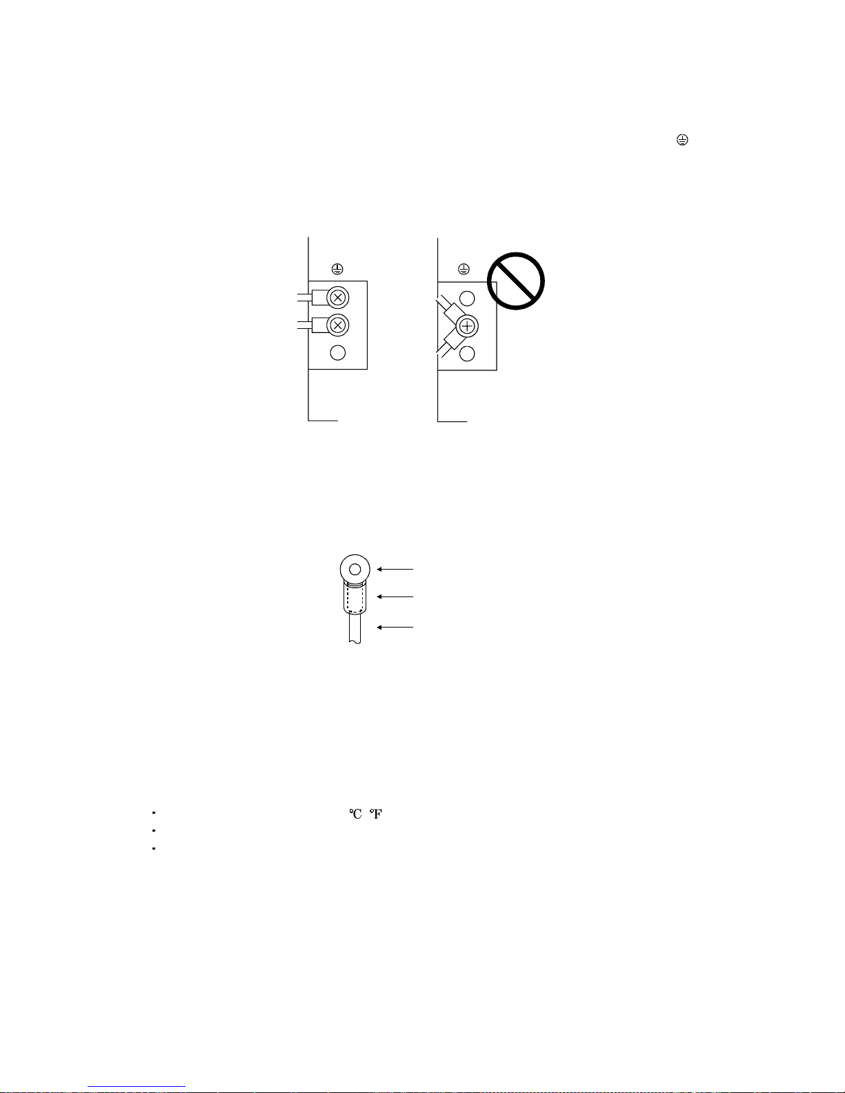
(b) Do not con nect two g round cable s to the same pro tective e arth (PE) terminal. Always c onnect the
cables to the terminals one-to-one.
PE terminals PE terminals
(c) If a leakage current breaker is used to prevent an electric shock, the protective earth (PE) terminals
of the servo ampli fi er mus t b e c onne ct ed t o t h e c orr es pondi n g eart h t ermi nal s.
(6) Wiring
(a) The cables to be connected to the terminal block of the servo amplifier must have crimping
terminals provided with insulating tubes to prevent contact with adjacent terminals.
Crimping terminal
Insulating tube
Cable
(b) Use the servo motor side power connector which complies with the EN Standard. The EN
Standard-compliant power connector sets are available from us as options. (Refer to Section 13.1.2)
(7) Auxiliary equipment and options
(a) The no-fuse breaker and magnetic contactor used should be the EN or IEC standard-compliant
products of the models described in Section 13.2.2.
(b) The sizes of the cable s described in Section 13.2.1 mee t the following requ irements. To meet th e
other requirements, follow Table 5 and Appendix C in EN60204-1.
Ambient tempera t ur e: 40 (104 ) [ ( )]
Sheath: PVC (polyvinyl chloride)
Installed on wall surface or open table tray
(c) Use the EMC filter for noise reduction.
(8) Performing EMC tests
When EMC tests are run on a machine/device into which the servo amplifier has been installed, it
must conform to the electromagnetic compatibility (immunity/emission) standards after it has
satisfied the operating environment/electrical equipment specifications.
For the other EMC directive guidelines on the servo amplifier, refer to the EMC Installation
Guidelines(IB(NA)67310).
A - 9
CONFORMANCE WITH UL/C-UL STANDARD
(1) Servo amplifiers and servo motors used (Acquisition schedule)
Use the servo amplifiers and servo motors which comply with the standard model.
Servo amplifier :MR-E-10A to MR-E-200A
Servo motor :HC-KFE
HC-SFE
(2) Installation
Install a fan of 1 00CFM (2.8 m
3
/min) air flow 4 in (10.16 cm) above the servo amplifier or provide
cooling of at least equivalent capability.
(3) Short circuit rating
This servo amplifier conforms to the circuit whose peak current is limited to 5000A or less. Having
been subjected to the short-circuit tests of the UL in the alternating-current circuit, the servo
amplifier conforms to the above circuit.
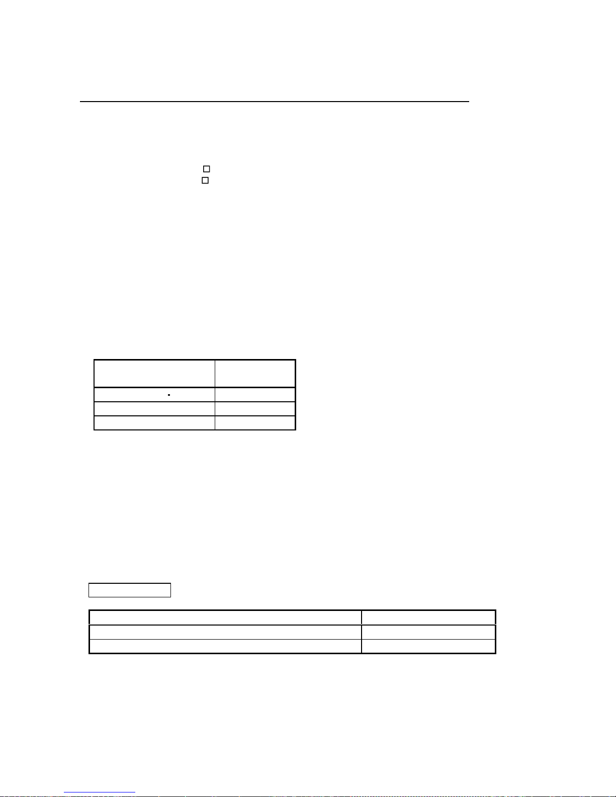
(4) Capacitor discharge time
The capacitor disch arg e time is as li sted below . To ensu re saf ety , do no t to uch the ch argin g sec tion f or
10 minutes after power-off.
Servo amplifier
Discharge time
[min]
MR-E-10A 20A 1
MR-E-40A 2
MR-E-70A to 200A 3
(5) Options and auxiliary equipment
Use UL/C-UL standard-compliant products.
(6) About wiring protection
For installation in United States, branch circuit prot ecti on must be provided, in accordance with the
National Electrical Code and any applicable local codes.
For installation in Canada, branch circuit protection must be provided, in accordance with the Canada
Electrical Code and any applicable provincial codes.
<<About the manual s>>
Relevant manuals
Manual name Manual No.
MR-E Series To Use the AC Servo Safely IB(NA)0300057
EMC Installation Guidelines IB(NA)67310

A - 10
MEMO

1
CONTENTS
1. FUNCTIONS AND CONFIGURATION 1- 1 to 1-10
1.1 Introduction.............................................................................................................................................. 1- 1
1.2 Function block diagram ..........................................................................................................................1- 2
1.3 Servo amplifier standard specifications................................................................................................1- 3
1.4 Function list .............................................................................................................................................1- 4
1.5 Model code definition ..............................................................................................................................1- 6
1.6 Combination with servo motor............................................................................................... ................1- 6
1.7 Parts identification..................................................................................................................................1- 7
1.8 Servo system with auxiliary equipment................................................................................................1- 9
2. INSTALLATION 2- 1 to 2- 4
2.1 Environmental conditions.......................................................................................................................2- 1
2.2 Installation direction and clearances ....................................................................................................2- 2
2.3 Keep out foreign materials .....................................................................................................................2- 3
2.4 Cable stress ..............................................................................................................................................2- 3
3. SIGNALS AND WIRING 3- 1 to 3- 48
3.1 Standard connection example ................................................................................................................3- 2
3.1.1 Position control mode .......................................................................................................................3- 2
3.1.2 Internal speed control mode ............................................................................................................3- 8
3.2 Internal connection diagram of servo amplifier ...................................................................................3- 9
3.3 I/O signals................................................................................................................................................3-10
3.3.1 Connectors and signal arrangements............................................................................................3-10
3.3.2 Signal explanations .........................................................................................................................3-13
3.4 Detailed description of the signals........................................................................................................3-19
3.4.1 Position control mode ......................................................................................................................3-19
3.4.2 Internal speed control mode ...........................................................................................................3-24
3.4.3 Position/internal speed control change mode................................................................................3-26
3.5 Alarm occurrence timing chart .............................................................................................................3-28
3.6 Interfaces.................................................................................................................................................3-29
3.6.1 Common line ....................................................................................................................................3-29
3.6.2 Detailed description of the interfaces............................................................................................3-30
3.7 Input power supply circuit.....................................................................................................................3-34
3.7.1 Connection example.........................................................................................................................3-34
3.7.2 Terminals..........................................................................................................................................3-35
3.7.3 Power-on sequence...........................................................................................................................3-36
3.8 Connection of servo amplifier and servo motor...................................................................................3-37
3.8.1 Connection instructions ..................................................................................................................3-37
3.8.2 Connection diagram.........................................................................................................................3-37
3.8.3 I/O terminals....................................................................................................................................3-39
3.9 Servo motor with electromagnetic brake .............................................................................................3-41
3.10 Grounding .............................................................................................................................................3-44
3.11 Servo amplifier connectors (CNP1, CNP2) wiring method
(When MR-ECPN1-B and MR-ECPN2-B of an option are used.)...................................................3-45
3.12 Instructions for the 3M connector.......................................................................................................3-48

2
4. OPERATION 4- 1 to 4- 6
4.1 When switching power on for the first time..........................................................................................4- 1
4.2 Startup......................................................................................................................................................4- 2
4.2.1 Selection of control mode..................................................................................................................4- 2
4.2.2 Position control mode .......................................................................................................................4- 2
4.2.3 Internal speed control mode ............................................................................................................4- 4
5. PARAMETERS 5- 1 to 5- 30
5.1 Parameter list..........................................................................................................................................5- 1
5.1.1 Parameter write inhibit ...................................................................................................................5- 1
5.1.2 Lists....................................................................................................................................................5- 2
5.2 Detailed description ...............................................................................................................................5-25
5.2.1 Electronic gear .................................................................................................................................5-25
5.2.2 Analog monitor.................................................................................................................................5-26
5.2.3 Using forward/reverse rotation stroke end to change the stopping pattern..............................5-29
5.2.4 Alarm history clear..........................................................................................................................5-29
5.2.5 Position smoothing ..........................................................................................................................5-30
6. DISPLAY AND OPERATION 6- 1 to 6-14
6.1 Display flowchart..................................................................................................................................... 6- 1
6.2 Status display ..........................................................................................................................................6- 2
6.2.1 Display examples.............................................................................................................................. 6- 2
6.2.2 Status display list.............................................................................................................................6- 3
6.2.3 Changing the status display screen................................................................................................6- 4
6.3 Diagnostic mode.......................................................................................................................................6- 5
6.4 Alarm mode................................................................................................................. .............................6- 6
6.5 Parameter mode ......................................................................................................................................6- 7
6.6 External I/O signal display.....................................................................................................................6- 8
6.7 Output signal (DO) forced output .........................................................................................................6-10
6.8 Test operation mode........................................................................................................ .......................6-11
6.8.1 Mode change.....................................................................................................................................6-11
6.8.2 Jog operation ....................................................................................................................................6-12
6.8.3 Positioning operation....................................................................................................................... 6-13
6.8.4 Motor-less operation........................................................................................................................6-14
7. GENERAL GAIN ADJUSTMENT 7- 1 to 7-10
7.1 Different adjustment methods ...............................................................................................................7- 1
7.1.1 Adjustment on a single servo amplifier..........................................................................................7- 1
7.1.2 Adjustment using servo configuration software............................................................................7- 2
7.2 Auto tuning ..............................................................................................................................................7- 3
7.2.1 Auto tuning mode .............................................................................................................................7- 3
7.2.2 Auto tuning mode operation............................................................................................................7- 4
7.2.3 Adjustment procedure by auto tuning............................................................................................7- 5
7.2.4 Response level setting in auto tuning mode...................................................................................7- 6

3
7.3 Manual mode 1 (simple manual adjustment).......................................................................................7- 7
7.3.1 Operation of manual mode 1 ...........................................................................................................7- 7
7.3.2 Adjustment by manual mode 1 .......................................................................................................7- 7
7.4 Interpolation mode .................................................................................................................................7-10
8. SPECIAL ADJUSTMENT FUNCTIONS 8- 1 to 8-10
8.1 Function block diagram ..........................................................................................................................8- 1
8.2 Machine resonance suppression filter ...................................................................................................8- 1
8.3 Adaptive vibration suppression control.................................................................................................8- 3
8.4 Low-pass filter .........................................................................................................................................8- 4
8.5 Gain changing function...........................................................................................................................8- 5
8.5.1 Applications....................................................................................................................................... 8- 5
8.5.2 Function block diagram....................................................................................................................8- 5
8.5.3 Parameters ........................................................................................................................................8- 6
8.5.4 Gain changing operation..................................................................................................................8- 8
9. INSPECTION 9- 1 to 9- 2
10. TROUBLESHOOTING 10- 1 to 10-12
10.1 Trouble at start-up ..............................................................................................................................10- 1
10.1.1 Position control mode...................................................................................................................10- 1
10.1.2 Internal speed control mode ........................................................................................................10- 4
10.2 When alarm or warning has occurred...............................................................................................10- 5
10.2.1 Alarms and warning list ..............................................................................................................10- 5
10.2.2 Remedies for alarms.....................................................................................................................10- 6
10.2.3 Remedies for warnings................................................................................................................10-11
11. OUTLINE DIMENSION DRAWINGS 11- 1 to 11- 8
11.1 Servo amplifiers...................................................................................................................................11- 1
11.2 Connectors............................................................................................................................................11- 5
12. CHARACTERISTICS 12- 1 to 12- 4
12.1 Overload protection characteristics...................................................................................................12- 1
12.2 Power supply equipment capacity and generated loss ....................................................................12- 1
12.3 Dynamic brake characteristics...........................................................................................................12- 3
12.4 Encoder cable flexing life................................................................................................ ....................12- 4
13. OPTIONS AND AUXILIARY EQUIPMENT 13- 1 to 13-32
13.1 Options..................................................................................................................................................13- 1
13.1.1 Regenerative brake options.........................................................................................................13- 1
13.1.2 Cables and connectors..................................................................................................................13- 6
13.1.3 Analog monitor, RS-232C branch cable (MR-E3CBL15-P).....................................................13-19
13.1.4 Servo configurations software....................................................................................................13-20

4
13.2 Auxiliary equipment ..........................................................................................................................13-21
13.2.1 Recommended wires....................................................................................................................13-21
13.2.2 No-fuse breakers, fuses, magnetic contactors...........................................................................13-23
13.2.3 Power factor improving reactors................................................................................................13-23
13.2.4 Relays............................................................................................................................................13-24
13.2.5 Surge absorbers ...........................................................................................................................13-24
13.2.6 Noise reduction techniques.........................................................................................................13-24
13.2.7 Leakage current breaker.............................................................................................................13-30
13.2.8 EMC filter.....................................................................................................................................13-32
14. SERVO MOTOR 14- 1 to 14- 38
14.1 Compliance with the overseas standards..........................................................................................14- 1
14.1.1 Compliance with EC directives...................................................................................................14- 1
14.1.2 Conformance with UL/C-UL standard.......................................................................................14- 1
14.2 Model name make-up..........................................................................................................................14- 2
14.3 Parts identification..............................................................................................................................14- 4
14.4 Installation...........................................................................................................................................14- 5
14.4.1 Environmental conditions............................................................................................................14- 6
14.4.2 Installation orientation................................................................................................................14- 6
14.4.3 Load mounting precautions.........................................................................................................14- 7
14.4.4 Permissible load for the shaft......................................................................................................14- 8
14.4.5 Protection from oil and water.....................................................................................................14-11
14.4.6 Cable .............................................................................................................................................14-12
14.5 Connectors used for servo motor wiring...........................................................................................14-13
14.5.1 HC-KFE series.............................................................................................................................14-13
14.5.2 HC-SFE series..............................................................................................................................14-13
14.6 Specifications ......................................................................................................................................14-19
14.6.1 Standard specifications...............................................................................................................14-19
14.6.2 Torque characteristics.................................................................................................................14-21
14.6.3 Servo motors with reduction gears............................................................................................14-22
14.6.4 Servo motors with special shafts................................................................................................14-25
14.6.5 D cut..............................................................................................................................................14-25
14.7 Characteristics....................................................................................................................................14-26
14.7.1 Electromagnetic brake characteristics......................................................................................14-26
14.7.2 Vibration rank..............................................................................................................................14-28
14.7.3 Machine Accuracies.....................................................................................................................14-28
14.8 Outline dimension drawing...............................................................................................................14-29
14.8.1 HC-KFE series.............................................................................................................................14-29
14.8.2 HC-SFE series..............................................................................................................................14-32
14.9 Outline dimension drawing (in inches) ............................................................................................14-34
14.9.1 HC-KFE series.............................................................................................................................14-34
14.9.2 HC-SFE series..............................................................................................................................14-37

5
15. MR-E-
AG SERVO AMPLIFIER COMPATIBLE WITH ANALOG INPUT 15- 1 to 15- 62
15.1. Functions and configuration..............................................................................................................15- 1
15.1.1 Introduction...................................................................................................................................15- 1
15.1.2 Function block diagram ...............................................................................................................15- 2
15.1.3 Servo amplifier standard specifications .....................................................................................15- 3
15.1.4 Model code definition....................................................................................................................15- 4
15.1.5 Parts identification.......................................................................................................................15- 4
15.1.6 Servo system with auxiliary equipment.....................................................................................15- 6
15.2. Signals and wiring..............................................................................................................................15- 8
15.2.1 Standard connection example .....................................................................................................15- 8
15.2.2 Internal connection diagram of servo amplifier .......................................................................15-11
15.2.3 Connectors and signal arrangements........................................................................................15-12
15.2.4 Signal explanations.....................................................................................................................15-14
15.2.5 Detailed description of the signals.............................................................................................15-18
15.3 Startup.................................................................................................................................................15-25
15.3.1 Speed control mode......................................................................................................................15-25
15.3.2 Torque control mode....................................................................................................................15-27
15.4 Parameters..........................................................................................................................................15-29
15.4.1 Item list.........................................................................................................................................15-29
15.4.2 Details list ....................................................................................................................................15-32
15.5 Display and operation........................................................................................................................15-51
15.5.1 Display flowchart.........................................................................................................................15-51
15.5.2 Status display...............................................................................................................................15-53
15.5.3 Diagnostic mode...........................................................................................................................15-55
15.5.4 External I/O signal display.........................................................................................................15-57
15.6. Troubleshooting.................................................................................................................................15-59
15.6.1 Trouble at start-up ......................................................................................................................15-59
15.6.2 Alarms and warning list .............................................................................................................15-61

6
MEMO

1 - 1
1. FUNCTIONS AND CONFIGURATION
1. FUNCTIONS AND CONFIGURATION
1.1 Introduction
The Mitsubishi MR-E series general-purpose AC servo is based on the MR-J2-Super series, and has the
same high performance and limited functions.
It has position control and internal speed control modes. Further, it can perform operation with the
control modes changed, e.g. position/internal speed control. Hence, it is applicable to a wide range of
fields, precision positioning and smooth speed control of machine tools and general industrial machines.
As this new series has the RS-232C or RS-422 serial communication function, a servo configuration
software-installed personal computer or the like can be used to perform parameter setting, test operation,
status display monitoring, gain adjustment, etc.
With real-time auto tuning, you can automatically adjust the servo gains according to the machine.
The MR-E series servo motor is equipped with an incremental position encoder that has the resolution of
10000 pulses/rev to ensure high precision positioning.
(1) Position control mode
An up to 500kpps high-speed pulse train is used to control the speed and direction of a motor and
execute precision positioning of 10000 pulses/rev resolution.
The position smoothing function provides a choice of two different modes appropriate for a machine, so
a smoother start/stop can be made in response to a sudden position command.
A torque lim it i s i m po se d o n the servo am plifier by the c lam p circuit to pr o tect the po w e r transistor in
the main circuit from overcurrent due to sudden acceleration/deceleration or overload. This torque
limit value can be changed to any value with the parameter.
(2) Internal spee d co nt rol mod e
The parameter-driven internal speed command (max. 7 speeds) is used to control the speed and
direction of a servo motor smoothly.
There are also the acceleration/deceleration time constant setting in response to speed command, the
servo lock function at a stop time.
1 - 2
1. FUNCTIONS AND CONFIGURATION
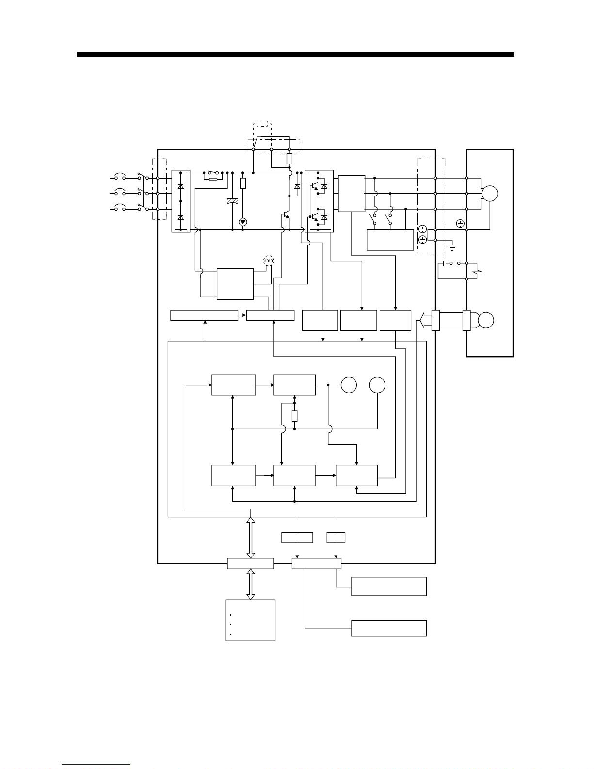
1.2 Function block diagram
The function block diagram of this servo is shown below.
Regenerative brake option
Servo amplifier
Current
detector
CHARGE
lamp
Servo motor
Regenerative
TR
(Note 1)
Regene rative brake
Base amplifier
Voltage
detection
Overcurrent
protection
Encoder
Dynamic
brake
Control
power
supply
Fan
(MR-E-200A only)
Electromagnetic
brake
Current
detection
Model position
control
Model speed
control
Pulse
input
Model
position
Actual position
control
Actual speed
control
Current
control
Model torque
Virtual
motor
Virtual
encoder
Model
speed
D I/O control
Servo on
Start
Failure, etc.
Controller
Analog monitor
(2 channels)
RADS
D
C
P
NFB MC
L
1
L
2
L
3
CN1
CN3
RS-232C
E2
I/F
CN2
U
V
W
U
V
W
SM
E1
RS-232C D/A
Power
supply
3-phase
200 to
230VAC,
1-phase
230VAC
(Note 2)
(Note 3)
(Note 3)
(Note 3)
(Note 3)
(Note 3)(Note 3)
Note:1. The built-in regenerative brake resistor is not provided for the MR-E-10A/20A.
2. The single-phase 230VAC can be used for MR-E-70A or smaller servo amplifier.
Connect the power supply cables to L
1
and L2 while leaving L3 open.
3. The control circuit connectors (CN1, CN2 and CN3) are safely isolated from main circuit terminals
(L
1
, L2, L3, U, V, W, P, C and D).
1 - 3
1. FUNCTIONS AND CONFIGURATION
1.3 Servo amplifier standard specifications
Servo Amplifier
MR-E-
Item
10A 20A 40A 70A 100A 200A
Voltage/frequency
3-phase 200 to 230VAC, 50/60Hz or 1-phase 230VAC,
50/60Hz
3-phase 200 to 230VAC,
50/60Hz
Permissible voltage fluctuation
3-phase 200 to 230VAC:
170 to 253VAC
1-phase 230VAC: 207 to 253VAC
3-phase 170 to 253VAC
Permissible frequency fluctuation Within 5%
Power supply
Power supply capacity Refer to Section12.2
System Sine-wave PWM control, curr ent c ontr ol syste m
Dynamic brake Built-in
Protective functions
Overcurrent shut-off, regenerative overvoltage shut-off, overload shut-off (electronic
thermal relay), encoder error protection, regenerative brake error protection,
undervoltage, instantaneous power failure protection, overspeed protection, excessive
error protection
Max. input pulse frequency 500kpps (for differential receiver), 200kpps (for open collector)
Command pulse multiplying factor Electronic gear A:1 to 65535 B:1 to 65535, 1/50 A/B 50
In-position range setting 0 to 10000 pulse (command pulse unit)
Error excessive 10 revolutions
Position control mode
Torque limit Set by parameter setting
Speed control range Internal speed command 1: 5000
Speed fluctuation ratio
0.01% or less (load fluctuation 0 to 100%)
0% or less (power fluctuation
10%)
Internal speed
control mode
Torque limit Set by parameter setting
Structure Self-cooled, open (IP0 0)
Force-cooling,
open (IP00)
[ ]0 to 55 (non-freezing)
Operation
[
] 32 to 131 (non-freezing)
[ ] 20 to 65 (non-freezing)
Ambient
temperature
Storage
[
] 4 to 149 (non-freezing)
Operation
Ambient
humidity
Storage
90%RH or less (n on- c o n d en si n g)
Ambient
Indoors (no direct s un li g ht )
Free from corrosive gas, flammable gas, oil mist, dust and dirt
Altitude Max. 1000m (3280ft) above sea level
5.9 [m/s2] or less
Environment
Vibration
19.4 [ft/s
2
] or less
[kg] 0.8 0.8 1.2 1.8 1.8 2.0
Weight
[lb] 1.8 1.8 2.6 4.0 4.0 4.4
1 - 4
1. FUNCTIONS AND CONFIGURATION
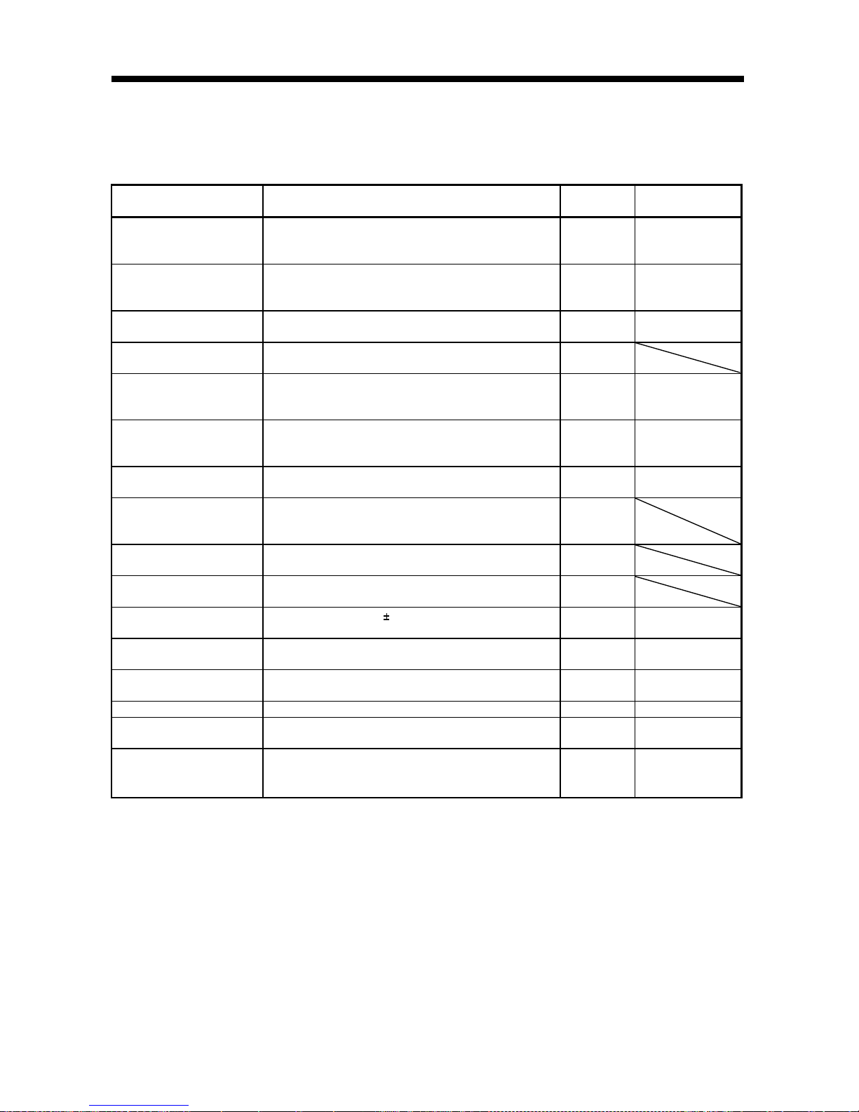
1.4 Function list
The following table lists the functions of this servo. For details of the functions, refer to the corresponding
chapters and sections.
Function Description
(Note)
Control mode
Refer to
Position control mode This servo is used as position control servo. P
Section 3.1.1
Section 3.4.1
Section 4.2.2
Internal speed control mode This servo is used as internal spe ed control servo. S
Section 3.1.2
Section 3.4.2
Section 4.2.3
Position/internal speed
control change mode
Using external input signal, control can be switched
between position control and internal speed control.
P/S Section 3.4.4
High-resolut ion encoder
High-resolution encoder of 131072 pulses/rev is used as a
servo motor e ncoder.
P, S, T
Gain changing function
You can switch between gains during rotation and gains
during stop or use an external input signal to change gains
during operation.
P, S Section 8.5
Adaptive vibration
suppression control
Servo amplifier detects mechanical resonance and sets filter
characteristics automatically to suppress mechanical
vibration.
P, S Section 8.3
Low-pass filter
Suppresses high-frequency resonance which occurs as servo
system response is increased.
P, S Section 8.4
Machine analyzer function
Analyzes the frequency characteristic of the mechanical
system by simply connecting a servo configuration softwareinstalled personal computer and servo amplifier.
P
Machine simulation
Can simulate machine motions on a personal computer
screen on the basis of the machine analyzer results.
P
Gain search function
Personal computer changes gains automatically and
searches for overshoot-free gains in a short time.
P
Slight vibration suppression
control
Suppresses vibration of 1 pulse produced at a servo motor
stop.
P Parameter No. 20
Electronic gear Input pulses can be multiplied by 1/50 to 50. P
Parameters No. 3, 4,
69 to 71
Auto tuning
Automatically adjusts the gain to optimum value if load
applied to the servo motor shaft varies.
P, S Chapter 7
Position smoothing Speed can be increased smoothly in response to input pulse. P Parameter No. 7
S-pattern acceleration/
deceleration time constant
Speed can be increased and decreased smoothly. S Parameter No. 13
Regenerative brake option
Used when the built-in regenerative brake resistor of the
servo amplifier does not have sufficient regenerative
capability for the regenerative power generated.
P, S Section 13.1.1

1 - 5
1. FUNCTIONS AND CONFIGURATION
Function Description
(Note)
Control mode
Refer to
Alarm history cl ea r Alarm history is cleared. P, S Parameter No. 16
Restart after instantaneous
power failure
If the input power supply volt age had reduced to cause an
alarm but has returned to normal, the servo motor can be
restarted by merely switching on the start signal.
S Parameter No. 20
Command pulse selection
Command pulse train form can be selected from among four
different types.
P Parameter No. 21
Input signal selection
Forward rotation start, reverse rotation start, servo-on and
other input signals can be assigned to any pins.
P, S
Parameters
No. 43 to 48
Torque limit Servo motor torque can be limited to any value. P, S
Section 3.4.1 (5)
Parameter No. 28
Status display
Servo status is shown on the 5-digit, 7-segment LED
display
P, S Section 6.2
External I/O signal display
ON/OFF statuses of external I/O signals are shown on the
display.
P, S Section 6.6
Output signal (DO)
forced output
Output signal can be forced on/off independently of the
servo status.
Use this function for output signal wiring check, etc.
P, S Section 6.7
Test operation mode
Servo motor can be run from the operation section of the
servo amplifier without the star t signal entered.
P, S Section 6.8
Analog monitor output Servo status is output in terms of voltage in real time. P, S Parameter No. 17
Servo configuration s oft w are
Using a personal computer, parameter setting, test
operation, status display, etc. can be performed.
P, S Section 13.1.8
Alarm code output
If an alarm has occurred, the corresponding alarm number
is output in 3-bit code.
P, S Section 10.2.1
Note:P: Position control mode, S: Internal speed control mode
P/S: Position/internal speed control change mode
1 - 6
1. FUNCTIONS AND CONFIGURATION
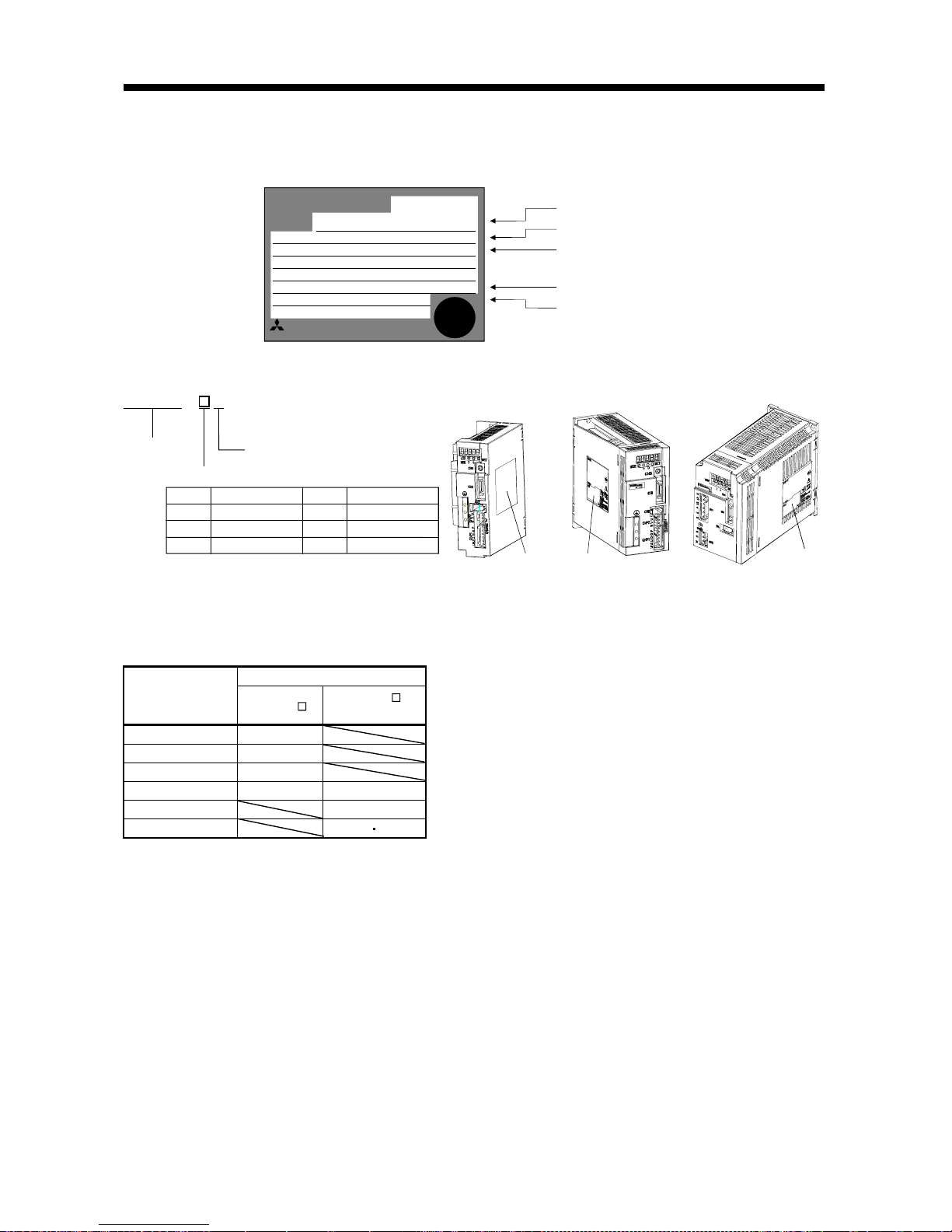
1.5 Model code definition
(1) Rating plate
MR-E-40A
MITSUBISHI
AC SERVO
MADE IN JAPAN
MODEL
MITSUBISHI ELECTRIC CORPORATION
AC SERVO
PASSED
POWER
INPUT
OUTPUT
SERIAL
:400W
:2.6A 3PH200-230V 50Hz
:2.6A3PH200-230V 60Hz
:170V 0-360Hz 2.8A
:XXXXYYYYY
:TCXXXAYYYGZZ
:
Model
Capacity
Applicable power supply
Rated output current
Serial number
(2) Model
70
750
40 400
10
100
20
100
200
1000
200 2000
MR-E-200AMR-E-40A or less MR-E -70A, 100A
Rating plate Rating plate
Rating plate
Series
Rated output
General-purpose interface
Symbol
Rated output [W]
Symbol
Rated output [W]
- AMR - E
1.6 Combination with servo motor
The following table li st s combin a tions of servo amplifiers and servo mo to rs. T he sa me co mb ina t io ns ap ply
to the models with electromagnetic brakes and the models with reduction gears.
Servo motors
Servo amplifier
HC-KFE
HC-SFE
2000r/min
MR-E-10A 13
MR-E-20A 23
MR-E-40A 43
MR-E-70A 73 52
MR-E-100A 102
MR-E-200A 152 202
1 - 7
1. FUNCTIONS AND CONFIGURATION
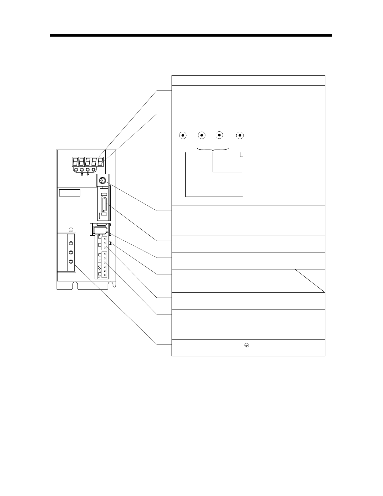
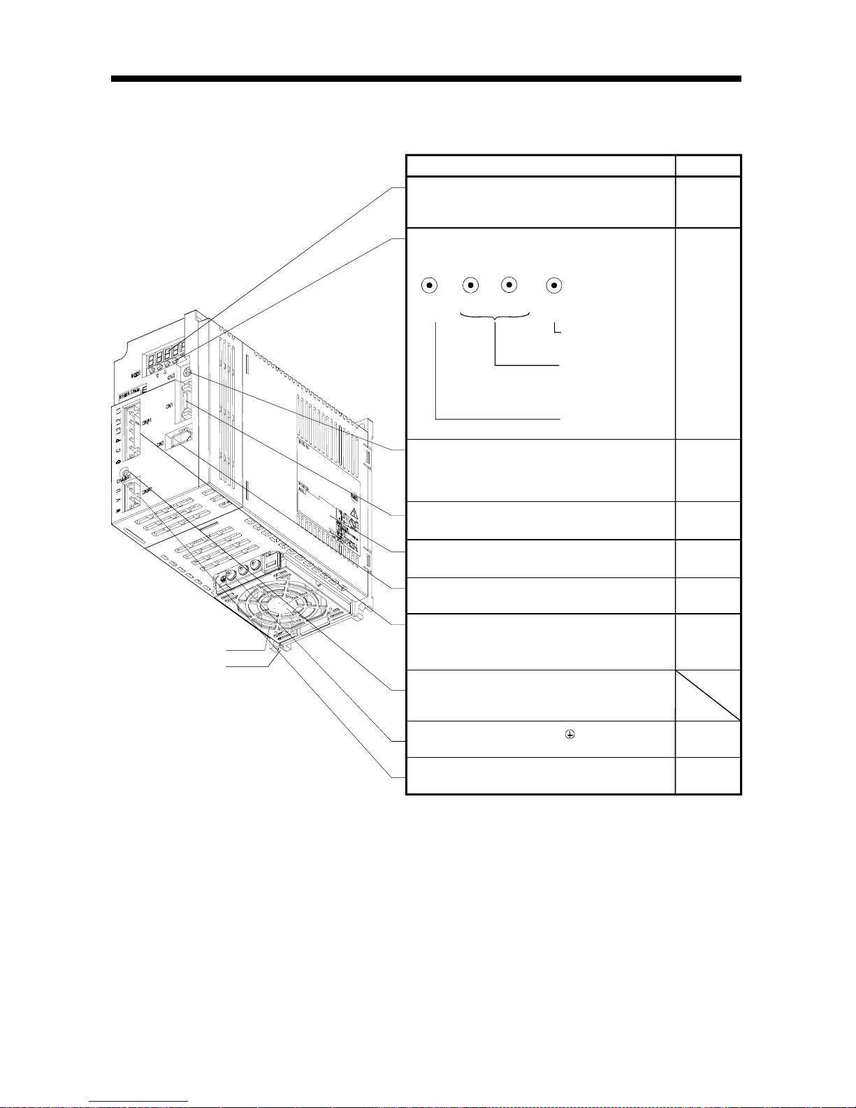
1.7 Parts identification
(1) MR-E-100A or less
MODE
CN3
SET
CN1
CN2
CNP2
CNP1
L3L2 L1 D C P W V U
CHARGE
MITSUBISHI
MR-
Chapter6
Display
The 5-digit, seven-segment LED shows the servo
status and alarm number.
Used to set data.
Used to change the
display or data in each
mode.
Used to change the
mode.
MODE
UP
DOWN
SET
Operation section
Used to perform status display, diagnostic, alarm and
parameter setting operations.
Chapter6
Communication connector (CN3)
Used to connect a command device (RS-232C)
and output analog monitor data.
I/O signal conn e ct or (CN1)
Used to connect digital I/O signal s.
Section3.3
Encoder connector ( C N2 )
Connector for connection of the servo motor encoder.
Section3.3
Section13.1.2
Charge lamp
Lit to indicate that the main circuit is charged. While
this lamp is lit, do not reconnect the cables.
Protective earth (PE) terminal ( )
Ground terminal.
Section3.10
Section11.1
Section3.3
Section13.1.2
Chapter14
Section3.7
Section11.1
Section3.7
Section11.1
Section13.1.1
Refer to
Name/Application
Motor power supply conn e ctor (CNP2)
Used to connect the servo mo tor.
Power supply/regenerative connector (CNP1)
Used to connect the input power supply and
regenerative brake option.
1 - 8
1. FUNCTIONS AND CONFIGURATION
(2) MR-E-200A
Refer to
Name/Application
Chapter6
Display
The 5-digit, seven-segment LED shows the servo
status and alarm number.
Used to set data.
Used to change the
display or data in each
mode.
Used to change the
mode.
MODE
UP
DOWN
SET
Operation section
Used to perform status display, diagnostic, alarm and
parameter setting operations.
Chapter6
Communication connector (CN3)
Used to connect a command device (RS232C)
and output analog monitor data.
Section3.3
Section13.1.2
Chapter14
I/O signal connector (CN1)
Used to connect digital I/O signals.
Section3.3
Name plate
Charge lamp
Lit to indicate that the main circuit is charged. While
this lamp is lit, do not reconnect the cables.
Encoder co nnector (C N2 )
Connector for connection of the servo motor enc oder.
Section1.5
Section3.3
Section13.1.2
Motor power supply connector (CNP2)
Used to connect the servo motor.
Protective earth (PE) terminal ( )
Ground terminal.
Power supply/regenerative connector (CNP1)
Used to connect the input power supply and
regenerative brake option.
Section3.7
Section11.1
Section3.7
Section11.1
Section13.1.1
Section3.10
Section11.1
Cooling fan
Installation notch
(4 places)
1 - 9
1. FUNCTIONS AND CONFIGURATION
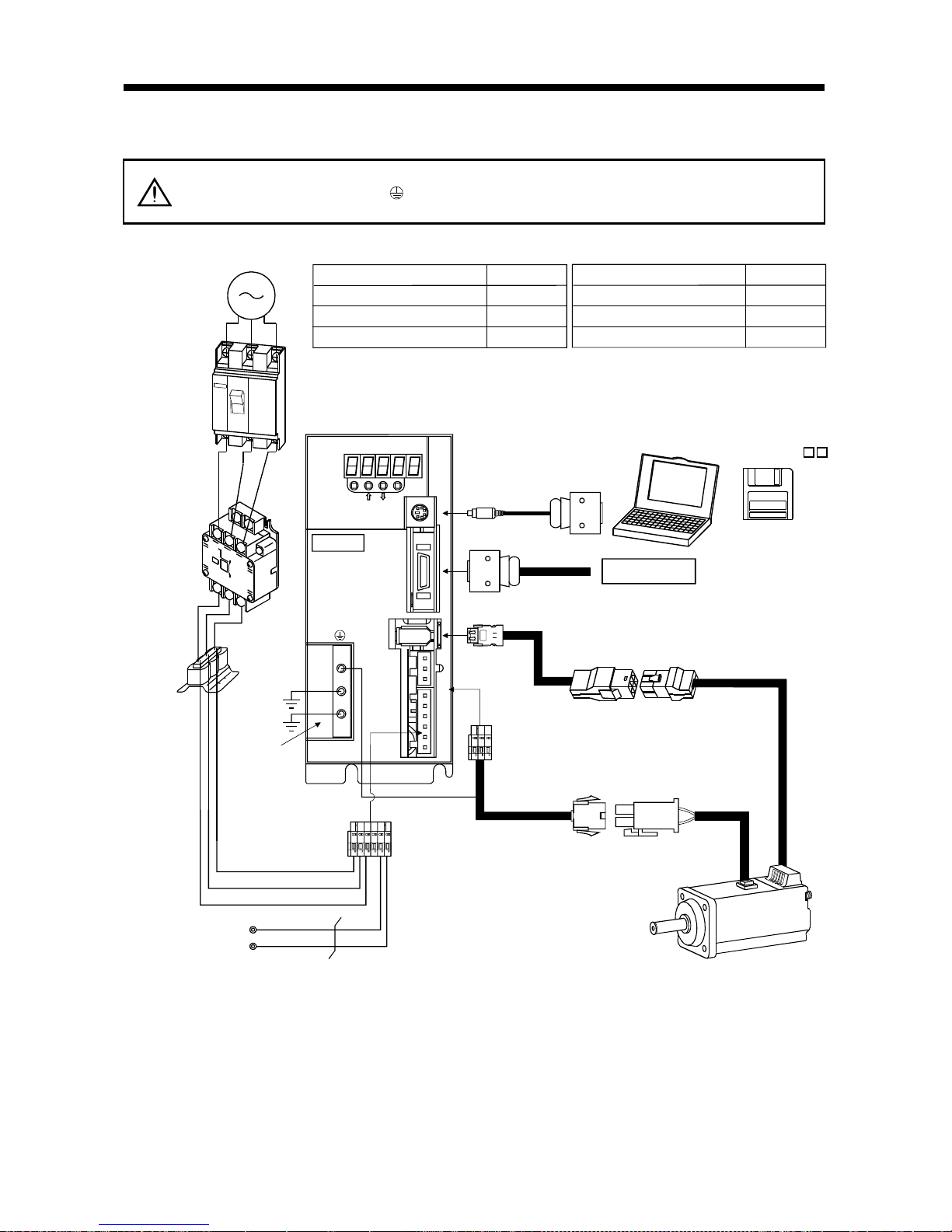
1.8 Servo system with auxiliary equipment
WARNING
To prevent an electric shock, always connect the protective earth (PE) terminal
(terminal m ar k ed
) of the servo amplifier to the prot ective ear th (PE) of the contr ol
box.
(1) MR-E-100A or less
MODE
CN3
SET
CN1
CN2
CNP2
CNP1
L3L2 L1 D C P W V U
CHARGE
MITSUBISHI
MR-E-
P
C
L
3
L
2
L
1
(Note 2)
3-phase 200V
to 230VAC power
supply or
1-phase 230VAC
power supply
No-fuse breaker
(NFB) or fuse
Magnetic
contactor
(MC)
To CN2
To CN1
To CN3
Protective earth
(PE) terminal
Servo motor
Personal
computer
Servo amplifier
Regenerative option
Options and auxiliary equipment
No-fuse breaker
Magnetic contactor
Servo configuration software
Regenera tive option
Refer to
Section 13.2.2
Section 13.2.2
Section 13.1.4
Section 13.1.1
(Note 1)
Encoder cable
Options and auxiliary equipment
Refer to
Cables
Section 13.2.1
Command device
(Note 1)
Power supply lead
Power
factor
improving
reactor
(FR-BAL)
Power factor improving reactor
Section 13.2.3
Servo configuration
software
MRZJW3-SETUP1
Note: 1. The HC-SFE series have cannon connectors.
2. A 1-phase 230VAC power supply may be used with the servo amplifier of MR-E-70A or less. Connect the power supply to
L
1
and L2 terminals and leave L3 open.
1 - 10
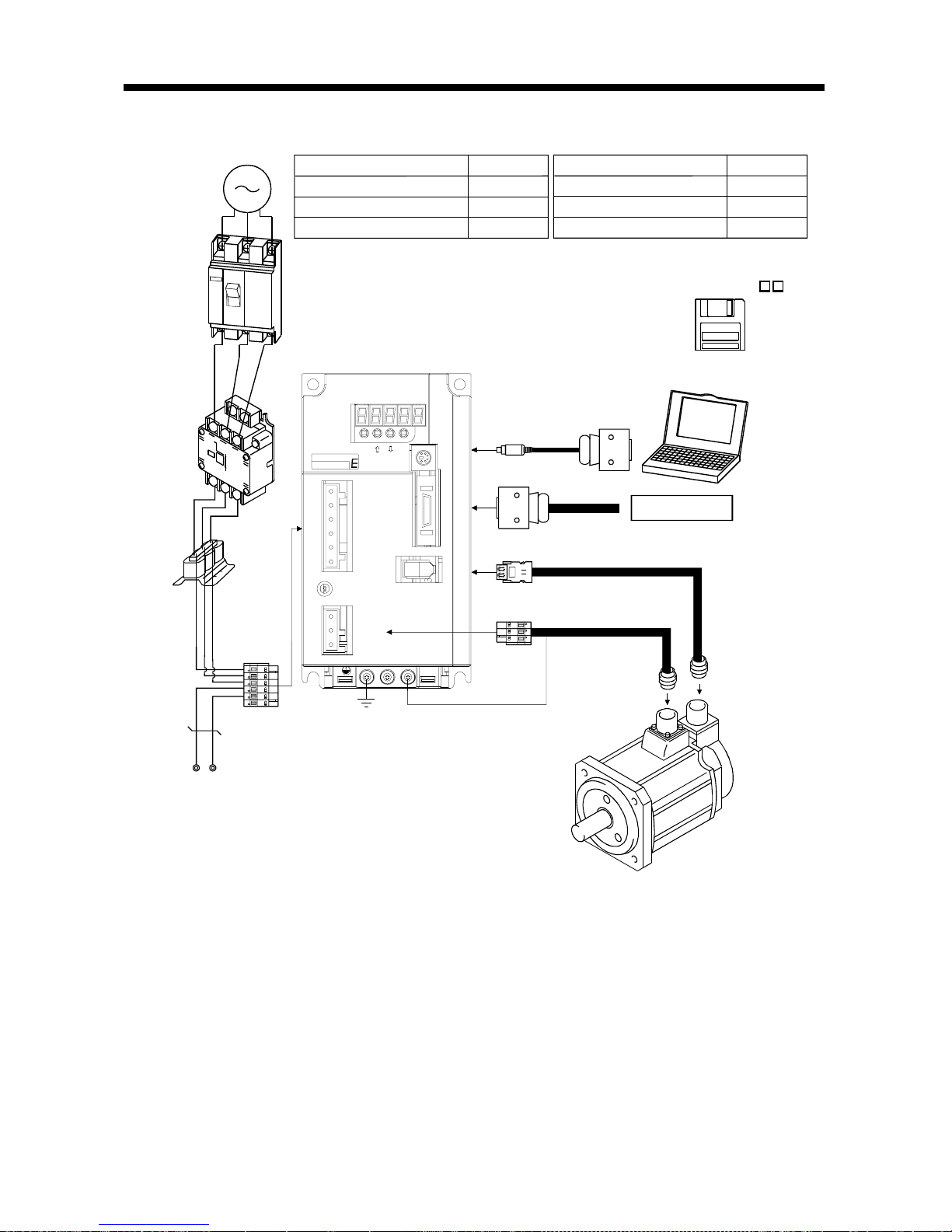
1. FUNCTIONS AND CONFIGURATION
(2) MR-E-200A
L
3
L
2
L
1
DC L3PL1L2
CHARGE
CNP2
CNP1
CN1
CN2
UVW
CN3
MODE
SET
MITSUBIS HI
EZMotion
P
C
Options and auxiliary equipment
No-fuse breaker
Magnetic contactor
Servo configuration software
Regene rative op ti on
Refer to
Section 13.2.2
Section 13.2.2
Section 13.1.4
Section 13.1.1
Options and auxiliary equipment
Refer to
Cables Section 13.2.1
Power factor improving reactor
Section 13.2.3
Power
f
actor
improving
reactor
(FR-BAL)
3-phase 200V
to 230VAC
power supply
No-fuse
breaker
(NFB) or
fuse
Magnetic
contactor
(MC)
To CN2
To CN1
To CN3
Servo amplifier
Regene rative op ti on
Personal
computer
Command device
Servo configuration
software
MRZJW3-SETUP1
To CNP2
2 - 1
2. INSTALLATION
2. INSTALLATION
CAUTION
Stacking in excess of the limited number of products is not allowed.
Install the equipment to incombustibles. Installing them directly or close to
combustibles will led to a fire.
Install the equipment in a load-bearing place in accordance with this Instruction
Manual.
Do not get on or put heavy load on the equipment to prevent injury.
Use the equipment within the specified environmental condition range.
Provide an adequate protection to prevent screws, metallic detritus and other
conductive matter or oil and other combustible matter from entering the servo
amplifier.
Do not block the intake/exhaust ports of the servo amplifier. Otherwise, a fault may
occur.
Do not subject the servo amplifier to drop impact or shock loads as they are
precision equipment.
Do not install or operate a faulty servo amplifier.
When the product has been stored for an extended period of time, consult
Mitsubishi.
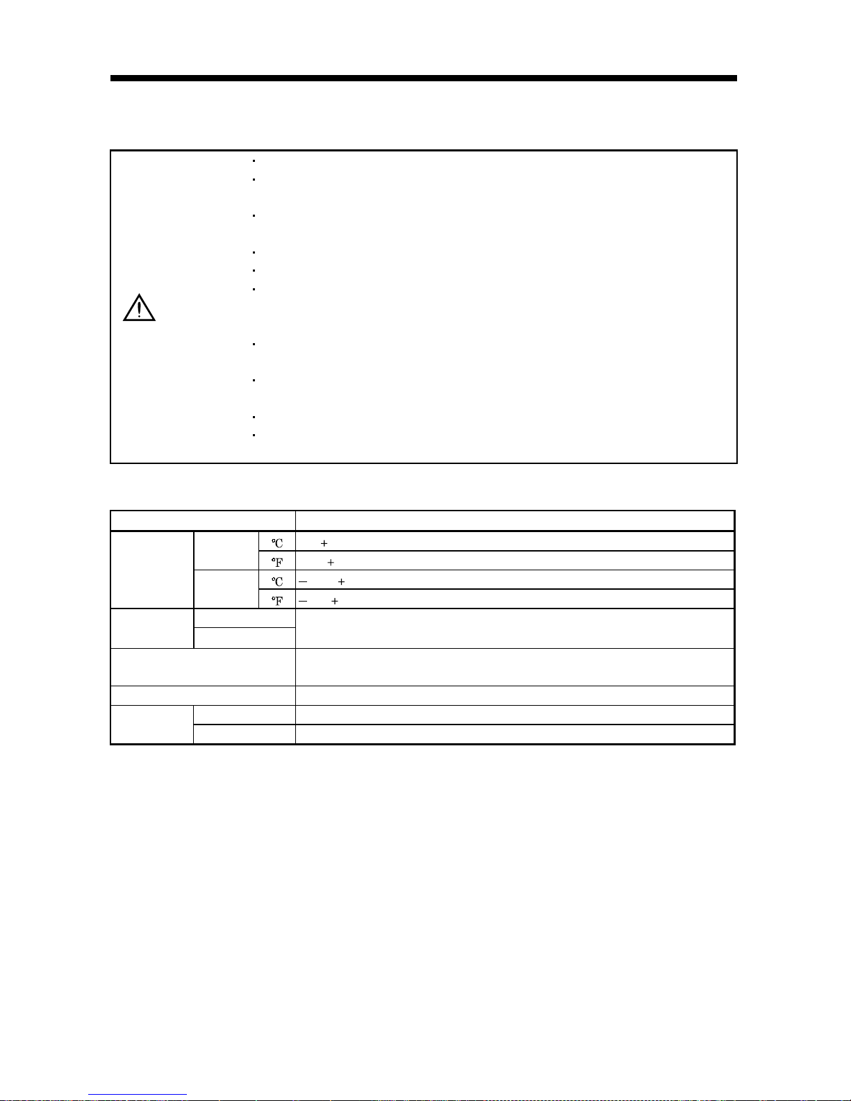
2.1 Environmental conditions
Environment Conditions
[ ]0 to 55 (non-freezing)
Operation
[
] 32 to 131 (non-freezing)
[ ] 20 to 65 (non-freezing)
Ambient
temperature
Storage
[
] 4 to 149 (non-freezing)
Operation
Ambient
humidity
Storage
90%RH or less (non-condensing)
Ambience
Indoors (no direct sunlight)
Free from corrosive gas, flammable gas, oil mist, dust and dirt
Altitude Max. 1000m (3280 ft) above sea level
[m/s2] 5.9 [m/s2] or less
Vibration
[ft/s
2
] 19.4 [ft/s2] or less
2 - 2
2. INSTALLATION
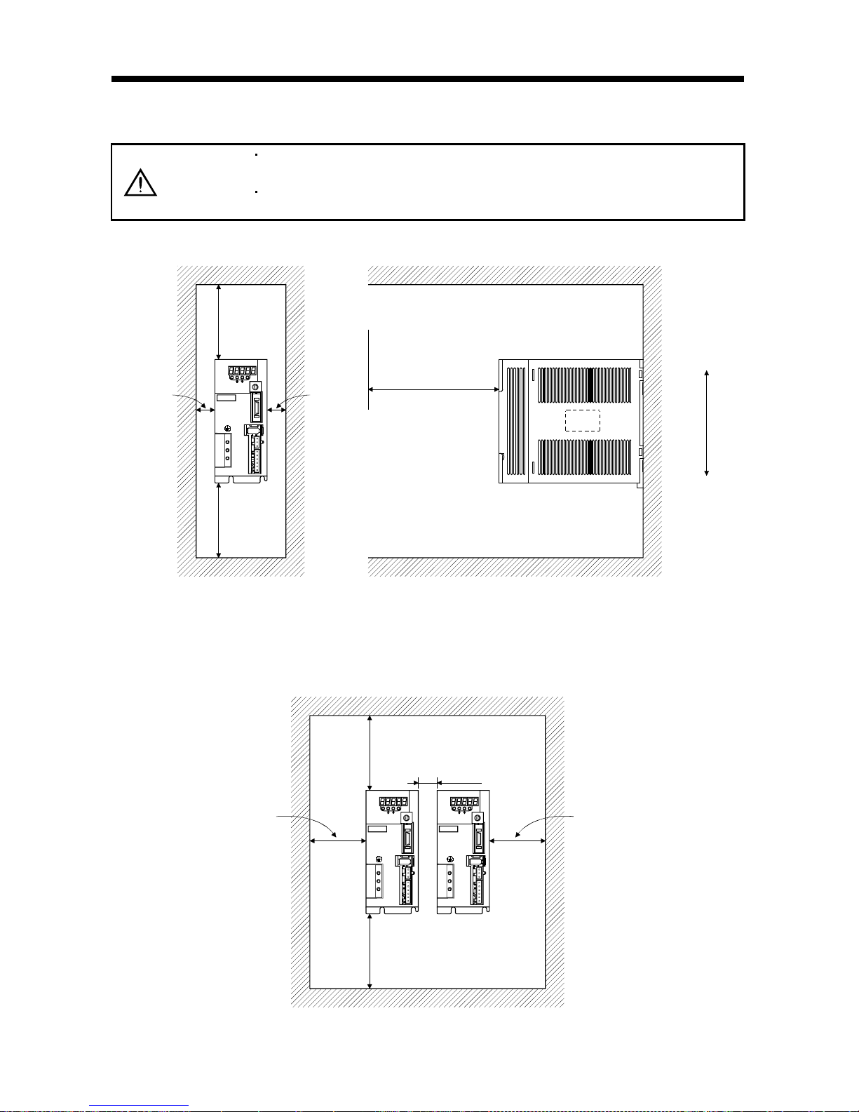
2.2 Installation direction and clearances
CAUTION
The equipment mus t be installe d in the specif ied direct ion. Other wise, a fau lt may
occur.
Leave specified clearances between the servo amplifier and control box inside
walls or other equipment.
(1) Installation of one servo amplifier
MODE
CN3
SET
CN1
CN2
CNP2
CNP1
L3L2 L1 D C P W V U
CHARGE
MITSUBISHI
MR-
Control box Control box
10mm
(0.4 in.)
or more
10mm
(0.4 in.)
or more
40mm
(1.6 in.)
or more
Servo
amplifier
40mm
(1.6 in.)
or more
Wiring clearance
Top
Bottom
(2.8 in.)
70mm
(2) Installation of two or more servo amplifiers
Leave a large clearance between the top of the servo amplifier and the internal surface of the control
box, and install a fan to prevent the internal temperature of the control box from exceeding the
environmental conditions.
MODE
CN3
SET
CN1
CN2
CNP2
CNP1
L3L2 L1 D C P W V U
CHARGE
MITSUBISHI
MR-
MODE
CN3
CN1
CN2
CNP2
CNP1
L3L2 L1 D C P W V U
CHARGE
MITSUBISHI
MR-
SET
Control box
30mm
(1.2 in.)
or more
30mm
(1.2 in.)
or more
10mm
(0.4 in.)
or more
40mm
(1.6 in.)
or more
100mm
(4.0 in.)
or more

2 - 3
2. INSTALLATION
(3) Others
When using heat generating equipment such as the regenerative brake option, install them with full
consideration of heat generation so that the servo amplifier is not affected.
Install the servo amplifier on a perpendicular wall in the correct vertical direction.
2.3 Keep out foreign materials
(1) When installing the unit in a control box, prevent drill chip s and wire fragmen ts from entering th e
servo amplifier.
(2) Prevent oil, water, metallic dust, etc. from entering the servo amplifier through openings in the control
box or a fan installed on the ceiling.
(3) When insta lling the con trol box in a place wher e there are much toxic g as, dirt and dust, co nduct an
air purge (force clean air into the control box from outside to make the internal pressure higher than
the external pressure) to prevent such materials from entering the control box.
2.4 Cable stress
(1) The way of clamping the cable must be fully examined so that flexing stress and cable's own weight
stress are not applied to the cable connection.
(2) For use in any application where the servo motor moves, fix the cables (encoder, power supply, brake)
supplied with the servo motor, and flex the optional encoder cable or the power supply and brake
wiring cables. Use the optional encoder cable within the flexing life range. Use the power supply and
brake wiring cables within the flexi ng lif e of the cabl es.
(3) Avoid any probability that the cable sheath might be cut by sharp chips, rubbed by a machine corner
or stamped by workers or vehicles.
(4) For installation on a machine where the servo motor will move, the flexing radius should be made as
large as possible. Refer to section 12.4 for the flexing life.
 Loading...