


PST596HN
MITSMI PST596HN, PST596IN, PST596JN, PST596KN, PST596LN Datasheet
...
MITSUMI
System Reset PST596~598
System Reset
Monolithic IC PST596~598 Series
Outline
These ICs function in a variety of CPU systems and other logic systems, to detect power supply voltage and
reset the system accurately when power is turned on or interrupted, and has a built-in fixed delay time
generating circuit. This series has been represented in the past by PST591~595, and these new system reset
ICs offer ultra-small size and low current consumption.
Features
1. Fixed delay time setting by counter timer
2. Low operating limit voltage 0.65V typ.
3. Hysteresis voltage provided in detection voltage 50mV typ.
4. Low current consumption I
CCH=15µA typ.
5. 3 delay time products available
PST596 50mS
PST597 100mS
PST598 200mS
6. Each product has 10 detection voltage ranks. C : 4.5V typ. H: 3.1V typ.
D : 4.2V typ. I : 2.9V typ.
E : 3.9V typ. J : 2.7V typ.
F : 3.6V typ. K : 2.5V typ.
G : 3.3V typ. L : 2.3V typ.
Package
SOT-25A (PST59 N) (with manual reset pin)
*
contains detection voltage rank.
Applications
1. Reset circuits in microcomputers, CPUs and MPUs
2. Logic circuit reset circuits.
3. Battery voltage check circuits.
4. Back-up power supply switching circuits.
5. Level detection circuits.
6. Mechanical reset circuits
MITSUMI
System Reset PST596~598
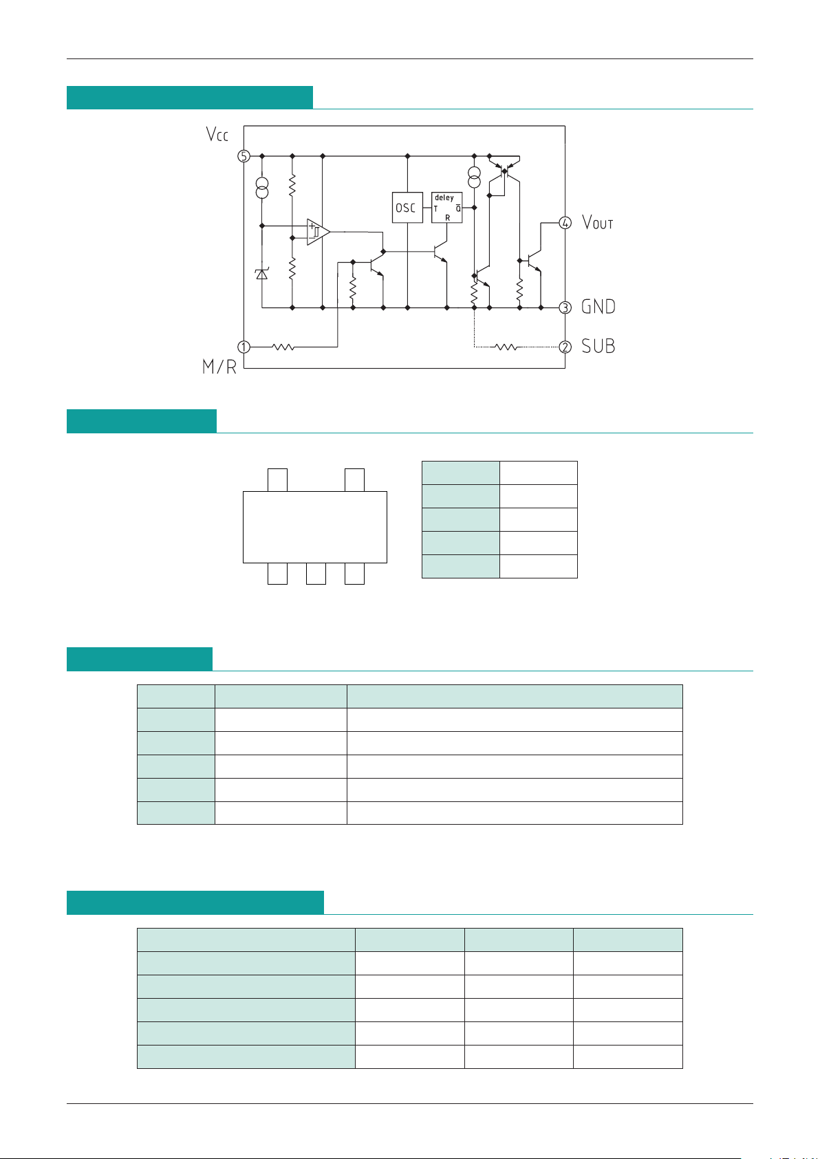
Equivalent Circuit Diagram
Pin Assignment
54
321
SOT
-
25
1 M/R
2 SUB
3 GND
4 V
OUT
5 VCC
Pin Description
Pin No. Pin name Function
1 M/R Manual reset pin
*
1
2 SUB SUB pin
*
2
3 GND GND pin
4 V
OUT Reset signal output pin
5 V
CC Power supply pin/Voltage detection pin
Absolute Maximum Ratings
(Ta=25
°
C)
Item Symbol Rating Units
Storage temperature T
STG
-
40~+125
°
C
Operating temperature T
OPR
-
20~+75
°
C
Power supply voltage V
CC max.
-
0.3~+12 V
Manual reset input voltage V
RES max.
-
0.3~+12 V
Allowable loss Pd 150 mW
*
1: Note that the oscilloscope may mis-operate if the M/R pin falls below
-
0.3V.
*
2: Connect to GND.
 Loading...