


MITSMI PST573EM, PST573F, PST573FM, PST573G, PST573GM Datasheet
...
MITSUMI |
System Reset PST573 |
|
|
System Reset
Monolithic IC PST573
Outline
This IC functions in a variety of CPU systems and other logic systems, to detect power supply voltage and reset the system accurately when power is turned on or interrupted. This ultra-low current consumption high reset type system reset IC was developed using high resistance process and low current circuit design technology.
Features
1. |
Ultra-low current consumption |
ICCH=450µA typ. |
ICCL=1µA typ. |
2. |
Low operating limit voltage |
0.65V typ. |
|
3. |
Output current high for ON |
-6mA typ. |
|
4. |
Hysteresis voltage provided in detection voltage |
50mV typ. |
|
5. |
10 ranks of detection voltage |
PST573 |
C : 4.5V typ. |
|
|
|
D : 4.2V typ. |
|
|
|
E : 3.9V typ. |
F : 3.6V typ.
G : 3.3V typ.
H : 3.1V typ. I : 2.9V typ.
J: 2.7V typ.
K: 2.5V typ.
L: 2.3V typ.
Package
MMP-3A (PST573
 M) TO-92A (PST573
 )
)
*
 contains detection voltage rank .
Applications
1.Reset circuits in microcomputers, CPUs and MPUs.
2.Logic circuit reset circuits.
3.Battery voltage check circuits.
4.Back-up power supply switching circuits.
5.Level detection circuits.
Pin Assignment
|
|
|
|
|
|
|
|
|
|
|
|
|
|
|
|
|
|
|
|
|
|
|
|
|
|
|
|
|
|
|
|
|
|
|
|
|
|
|
|
|
|
|
|
|
|
|
|
|
|
|
|
|
|
|
|
|
|
|
|
|
1 |
VCC |
|
1 |
3 |
|
|
1 |
VCC |
|
|||||
|
|
|
|
|
|
|
|
|
|
|
|
|
|
|
|
|
|
|
|
|
|
|
|
2 |
GND |
|
|
|
|
|
|
|
|
|
2 |
GND |
|
|
|
|
|
|
|
|
|
|
|
|
|
|
|
|
|
|
|
|
|
|
|
|
|
3 |
VOUT |
|
|
|
2 |
|
|
|
|
3 |
VOUT |
|
|
1 |
2 |
3 |
|
|
|
|
|
|
|
|
|
|
|
|
|
|
||
|
|
|
|
|
|
|
|
|
|
|
|
|
|
|||||
|
|
|
|
|
MMP-3A |
|
|
|
|
|
||||||||
TO-92A |
|
|
|
|
|
|
|
|
|
|||||||||
|
|
|
|
|
|
|
|
|
|
|
|
|
||||||
|
|
|
|
|
|
|
|
|
|
|
|
|
|
|
|
|
|
|
MITSUMI |
System Reset PST573 |
|
|
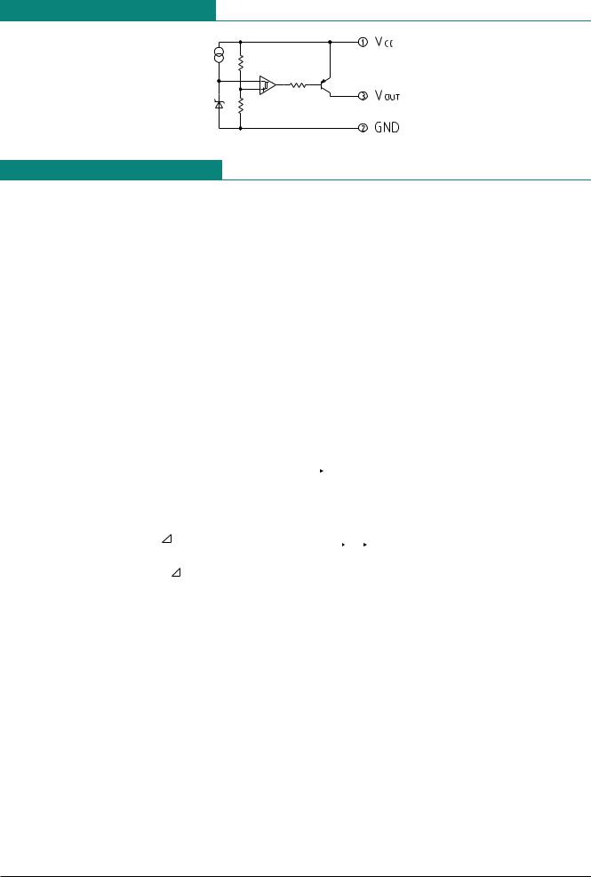
Equivalent Circuit Diagram
Absolute Maximum Ratings (Ta=25°C)
|
|
Item |
|
|
|
Symbol |
|
|
|
|
Rating |
|
|
Units |
|
|
|
|
||||||
|
|
|
|
|
|
|
|
|
|
|
|
|
|
|
|
|
|
|
|
|
|
|
|
|
|
|
Storage temperature |
|
|
TSTG |
|
|
|
-40~+125 |
|
|
|
°C |
|
|
|
|
|||||||
|
|
|
|
|
|
|
|
|
|
|
|
|
|
|
|
|
|
|
|
|
|
|
|
|
|
|
Operating temperature |
|
|
TOPR |
|
|
|
-20~+75 |
|
|
|
°C |
|
|
|
|
|||||||
|
|
|
|
|
|
|
|
|
|
|
|
|
|
|
|
|
|
|
|
|
|
|
|
|
|
|
Power supply voltage |
|
|
VCC max. |
|
|
|
-0.3~10 |
|
|
|
V |
|
|
|
|
|||||||
|
|
|
|
|
|
|
|
|
|
|
|
|
|
|
|
|
|
|
|
|
|
|
||
|
|
Allowable loss |
|
|
|
Pd |
|
|
200(MMP-3A) |
|
mW |
|
|
|
|
|||||||||
|
|
|
|
|
|
|
|
300(TO-92A) |
|
|
|
|
|
|
||||||||||
|
|
|
|
|
|
|
|
|
|
|
|
|
|
|
|
|
|
|
|
|
|
|||
|
|
|
|
|
|
|
|
|
|
|
|
|
|
|
|
|
|
|
|
|
||||
|
|
|
|
|
|
|
|
|
|
|
|
|
|
|
|
|
||||||||
Electrical Characteristics |
(Ta=25°C) (Except where noted otherwise, resistance unit is Ω ) |
|
||||||||||||||||||||||
|
|
|
|
|
|
|
|
|
|
|
|
|
|
|
|
|
|
|
|
|||||
|
|
Item |
Symbol |
Measurement |
Measurement conditions |
|
Min. |
Typ. |
|
Max. |
|
Units |
||||||||||||
|
|
|
|
circuit |
|
|
|
|
|
|
|
|
|
|
|
|
|
|
|
|
|
|
||
|
|
|
|
|
|
|
|
|
|
|
|
|
|
PST573C |
|
4.3 |
4.5 |
|
4.7 |
|
|
|
||
|
|
|
|
|
|
|
|
|
|
|
|
|
|
PST573D |
|
4.0 |
4.2 |
|
4.4 |
|
|
|
||
|
|
|
|
|
|
|
|
|
|
|
|
|
|
PST573E |
|
3.7 |
3.9 |
|
4.1 |
|
|
|
||
|
|
|
|
|
|
|
RL=4.7k |
|
|
PST573F |
|
3.4 |
3.6 |
|
3.8 |
|
|
|
||||||
|
|
|
|
|
|
|
|
|
PST573G |
|
3.1 |
3.3 |
|
3.5 |
|
|
|
|||||||
|
Detection voltage |
VS |
|
1 |
|
< |
|
|
|
|
|
|
|
|
|
|
V |
|||||||
|
|
|
|
|
|
|
|
|
|
|
|
|
|
|
|
|
|
|
||||||
|
|
|
VOL = VCC-0.4V |
|
PST573H |
|
2.9 |
3.1 |
|
3.3 |
|
|
||||||||||||
|
|
|
|
|
|
|
VCC=H |
|
L |
|
|
|
|
|
|
|
||||||||
|
|
|
|
|
|
|
|
|
|
|
|
|
|
|
|
|
|
|
|
|
||||
|
|
|
|
|
|
|
|
PST573I |
|
2.75 |
2.90 |
|
3.05 |
|
|
|
||||||||
|
|
|
|
|
|
|
|
|
|
|
|
|
|
|
|
|
|
|
||||||
|
|
|
|
|
|
|
|
|
|
|
|
|
|
PST573J |
|
2.55 |
2.70 |
|
2.85 |
|
|
|
||
|
|
|
|
|
|
|
|
|
|
|
|
|
|
PST573K |
|
2.35 |
2.50 |
|
2.65 |
|
|
|
||
|
|
|
|
|
|
|
|
|
|
|
|
|
|
PST573L |
|
2.15 |
2.30 |
|
2.45 |
|
|
|
||
|
Hysteresis voltage |
VS |
|
1 |
|
|
RL=4.7kΩ |
|
25 |
50 |
|
100 |
|
|
mV |
|||||||||
|
|
|
VCC=L |
|
H |
|
L |
|
|
|
|
|||||||||||||
|
|
|
|
|
|
|
|
|
|
|
|
|
|
|
|
|
|
|||||||
|
Detection voltage |
VS/ T |
|
1 |
|
|
RL=4.7kΩ |
|
|
|
±0.01 |
|
|
|
|
%/°C |
||||||||
|
temperature coefficient |
|
|
Ta=-20°C~+75°C |
|
|
|
|
|
|
|
|||||||||||||
|
|
|
|
|
|
|
|
|
|
|
|
|
|
|
|
|
|
|
|
|
|
|||
|
High level output voltage |
VOH |
|
1 |
|
VCC=VS min. -0.05V |
|
VCC |
|
|
|
|
|
V |
||||||||||
|
|
|
|
RL=4.7kΩ |
|
-0.4 |
|
|
|
|
|
|||||||||||||
|
|
|
|
|
|
|
|
|
|
|
|
|
|
|
||||||||||
|
Output leakage current |
IOH |
|
1 |
|
|
VCC=7.5V |
|
|
|
|
|
±0.1 |
|
|
µA |
||||||||
|
Circuit current while on |
ICCL |
|
1 |
|
VCC=VS min. -0.05V |
|
|
|
450 |
|
700 |
|
|
µA |
|||||||||
|
|
|
|
|
RL=∞ |
|
|
|
|
|
|
|
|
|||||||||||
|
|
|
|
|
|
|
|
|
|
|
|
|
|
|
|
|
|
|
|
|||||
|
Circuit current while off |
ICCH |
|
1 |
|
VCC=VS typ. /0.85V |
|
|
|
1.0 |
|
1.8 |
|
|
µA |
|||||||||
|
|
|
|
|
RL=∞ |
|
|
|
|
|
|
|
|
|||||||||||
|
|
|
|
|
|
|
|
|
|
|
|
|
|
|
|
|
|
|
|
|||||
|
"H"transport delay time |
tpLH |
|
2 |
|
RL=4.7kΩ |
*1 |
|
|
|
25 |
|
60 |
|
|
µS |
||||||||
|
|
|
|
|
|
|
|
CL=100pF |
|
|
|
|
|
|
|
|
|
|||||||
|
"L"transport delay time |
tpHL |
|
2 |
|
RL=4.7kΩ |
*1 |
|
|
|
8 |
|
20 |
|
|
µS |
||||||||
|
|
|
|
|
|
|
|
CL=100pF |
|
|
|
|
|
|
|
|
|
|||||||
|
Operation limit voltage |
VopL |
|
1 |
|
|
RL=4.7kΩ |
|
|
|
0.65 |
|
0.85 |
|
|
V |
||||||||
|
|
|
> |
|
|
|
|
|
|
|
|
|
|
|
|
|||||||||
|
|
|
|
|
|
|
|
|
|
|
|
|
|
|
|
|
|
|
|
|
|
|||
|
|
|
|
|
|
|
VOL = VCC-0.4V |
|
|
|
|
|
|
|
|
|
||||||||
|
Output current while on I |
IOL I |
|
1 |
|
VCC=VS min.-0.05V |
|
-2.0 |
-6.0 |
|
|
|
|
mA |
||||||||||
|
|
|
|
|
RL=0 |
|
|
|
|
|
|
|
||||||||||||
|
|
|
|
|
|
|
|
|
|
|
|
|
|
|
|
|
|
|
|
|||||
|
Output current while on II |
IOL II |
|
1 |
|
Ta=-20°C~+75°C *2 |
|
-1.5 |
|
|
|
|
|
mA |
||||||||||
|
|
|
|
|
|
|
|
|
RL=0 |
|
|
|
|
|
|
|
|
|
|
|
||||
*1 : tpLH : VCC=(VS typ.-0.4V) (VS typ.+0.4V), tpHL : VCC=(VS typ.+0.4V)
 (VS typ.-0.4V)
*2 : VCC=VS min.-0.15V
 Loading...