


MITSMI PST574C, PST574CM, PST574D, PST574DM, PST574E Datasheet
...
MITSUMI |
System Reset PST574 |
|
|
System Reset
Monolithic IC PST574
Outline
This IC functions in a variety of CPU systems and other logic systems, to detect power supply voltage and reset the system accurately when power is turned on or interrupted. This ultra-low current consumption low reset type system reset IC has a built-in fixed delay time generating circuit. It is ideal for use in multi-CPU systems because a fast-rising output waveform can be obtained.
Features
1. |
Ultra-low current consumption |
ICCH=7.5µA typ. ICCL=400µA typ. |
||
2. |
Low operating limit voltage |
0.65V typ. |
|
|
3. |
Output current high for ON |
30mA typ. |
|
|
4. |
Hysteresis voltage provided in detection voltage |
50mV typ. |
|
|
5. |
Built-in delay circuit with excellent delay time |
50mV typ. |
|
|
|
temperature characteristics |
|
|
|
6. |
10 ranks of detection voltage |
PST574 C : 4.5V typ. |
H : 3.1V typ. |
|
|
|
D : 4.2V typ. |
I |
: 2.9V typ. |
|
|
E : 3.9V typ. |
J |
: 2.7V typ. |
|
|
F : 3.6V typ. |
K : 2.5V typ. |
|
|
|
G : 3.3V typ. |
L : 2.3V typ. |
|
Package
MMP-3A (PST574 
 M) TO-92A (PST574
  )
)
*
 contains detection voltage rank .
Applications
1.Reset circuits in microcomputers, CPUs and MPUs (especially multi-CPU sets)
2.Logic circuit reset circuits.
3.Battery voltage check circuits.
4.Back-up power supply switching circuits.
5.Level detection circuits.
Pin Assignment
|
|
|
|
|
|
|
|
|
|
|
|
|
|
|
|
|
|
|
|
|
|
|
|
|
|
|
|
|
|
|
|
|
|
|
|
|
|
|
|
|
1 |
VCC |
|
|
1 |
3 |
|
|
1 |
VCC |
|||
|
|
|
|
||||||||||||||
|
|
|
|
|
2 |
GND |
|
|
|
|
|
|
|
|
|
2 |
GND |
|
|
|
|
|
3 |
VOUT |
|
|
|
2 |
|
|
|
|
3 |
VOUT |
|
1 |
2 |
3 |
|
|
|
|
|
|
|
|
|
|
|
|
|
||
|
|
|
|
|
|
|
|
|
|
|
|
|
|||||
|
|
|
|
|
MMP-3A |
|
|
|
|
||||||||
|
|
|
|
|
|
|
|
|
|
|
|
|
|
||||
TO-92A
MITSUMI |
System Reset PST574 |
|
|
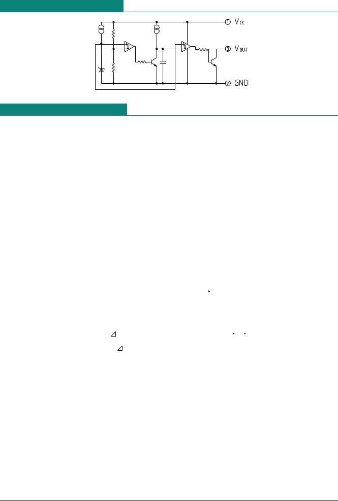
Equivalent Circuit Diagram
Absolute Maximum Ratings (Ta=25°C)
|
|
Item |
|
|
|
|
Symbol |
|
|
|
|
|
Rating |
|
|
|
|
Units |
|
|
|||||||
|
|
|
|
|
|
|
|
|
|
|
|
|
|
|
|
|
|
|
|
|
|
|
|||||
|
|
Storage temperature |
|
TSTG |
|
|
|
-40~+125 |
|
|
|
°C |
|
|
|
|
|||||||||||
|
|
|
|
|
|
|
|
|
|
|
|
|
|
|
|
|
|
|
|
|
|
|
|
|
|||
|
|
Operating temperature |
|
TOPR |
|
|
|
|
|
|
-20~+75 |
|
|
|
|
°C |
|
|
|
|
|||||||
|
|
|
|
|
|
|
|
|
|
|
|
|
|
|
|
|
|
|
|
|
|
|
|
|
|||
|
|
Power supply voltage |
|
VCC max. |
|
|
|
|
|
-0.3~10 |
|
|
|
|
V |
|
|
|
|
||||||||
|
|
|
|
|
|
|
|
|
|
|
|
|
|
|
|
|
|
|
|
|
|
|
|
|
|||
|
|
Allowable loss |
|
|
Pd |
|
|
|
200 (MMP-3A) |
|
mW |
|
|
||||||||||||||
|
|
|
|
|
|
|
300 (TO-92A) |
|
|
|
|||||||||||||||||
|
|
|
|
|
|
|
|
|
|
|
|
|
|
|
|
|
|||||||||||
|
|
|
|
|
|
|
|
|
|
|
|
|
|
|
|
|
|
|
|
|
|
||||||
|
|
|
|
|
|
|
|
|
|
|
|
|
|
|
|
|
|
|
|
|
|
|
|
|
|
|
|
Electrical Characteristics |
|
(Ta=25°C) (Except where noted otherwise, resistance unit is Ω ) |
|
||||||||||||||||||||||||
|
|
|
|
|
|
|
|
|
|
|
|
|
|
|
|
|
|
|
|
|
|
|
|
|
|
|
|
|
|
Item |
Symbol |
Measurement |
Measurement conditions |
Min. |
Typ. |
Max. |
Units |
||||||||||||||||||
|
|
|
circuit |
||||||||||||||||||||||||
|
|
|
|
|
|
|
|
|
|
|
|
|
|
|
|
|
|
|
|
|
|
|
|
|
|
|
|
|
|
|
|
|
|
|
|
|
|
|
|
|
|
|
|
|
PST574C |
4.3 |
4.5 |
|
4.7 |
|
|||||
|
|
|
|
|
|
|
|
|
|
|
|
|
|
|
|
|
|
|
|
|
|
|
|
|
|
||
|
|
|
|
|
|
|
|
|
|
|
|
|
|
|
|
|
PST574D |
4.0 |
4.2 |
|
4.4 |
|
|||||
|
|
|
|
|
|
|
|
|
|
|
|
|
|
|
|
|
|
|
|
|
|
|
|
|
|
||
|
|
|
|
|
|
|
|
|
|
|
|
|
|
|
|
|
PST574E |
3.7 |
3.9 |
|
4.1 |
|
|||||
|
|
|
|
|
|
|
|
|
|
|
|
|
|
|
|
|
|
|
|
|
|
|
|
|
|
||
|
|
|
|
|
|
|
|
|
RL=470 |
|
|
|
PST574F |
3.4 |
3.6 |
|
3.8 |
|
|||||||||
|
|
|
|
|
|
|
|
|
|
|
|
|
|
|
|
|
|
|
|
|
|
|
|||||
|
|
|
|
|
|
|
|
|
|
|
|
PST574G |
3.1 |
3.3 |
|
3.5 |
|
||||||||||
|
Detection voltage |
VS |
1 |
|
< |
0.4V |
|
|
|
V |
|||||||||||||||||
|
|
|
|
|
|
|
|
|
|
|
|
|
|
||||||||||||||
|
|
|
|
|
|
|
|
|
|
|
|
|
|
||||||||||||||
|
|
VOL = |
|
PST574H |
2.9 |
3.1 |
|
3.3 |
|||||||||||||||||||
|
|
|
|
|
|
|
|
|
VCC=H |
|
L |
|
|
|
|
||||||||||||
|
|
|
|
|
|
|
|
|
|
|
|
PST574I |
2.75 |
2.90 |
|
3.05 |
|
||||||||||
|
|
|
|
|
|
|
|
|
|
|
|
|
|
|
|
|
|
|
|||||||||
|
|
|
|
|
|
|
|
|
|
|
|
|
|
|
|
|
|
|
|
|
|
|
|
|
|
||
|
|
|
|
|
|
|
|
|
|
|
|
|
|
|
|
|
PST574J |
2.55 |
2.70 |
|
2.85 |
|
|||||
|
|
|
|
|
|
|
|
|
|
|
|
|
|
|
|
|
|
|
|
|
|
|
|
|
|
||
|
|
|
|
|
|
|
|
|
|
|
|
|
|
|
|
|
PST574K |
2.35 |
2.50 |
|
2.65 |
|
|||||
|
|
|
|
|
|
|
|
|
|
|
|
|
|
|
|
|
|
|
|
|
|
|
|
|
|
||
|
|
|
|
|
|
|
|
|
|
|
|
|
|
|
|
|
PST574L |
2.15 |
2.30 |
|
2.45 |
|
|||||
|
Hysteresis voltage |
|
|
VS |
1 |
|
RL=470, VCC=L |
|
|
H |
|
L |
25 |
50 |
|
100 |
mV |
||||||||||
|
|
|
|
|
|
|
|
||||||||||||||||||||
|
Detection voltage temperature |
VS/ |
T |
1 |
|
RL=470, Ta=-20°C~+75°C |
|
±0.01 |
|
|
%/°C |
||||||||||||||||
|
|
coefficient |
|
|
|
|
|||||||||||||||||||||
|
|
|
|
|
|
|
|
|
|
|
|
|
|
|
|
|
|
|
|
|
|
|
|
|
|
|
|
|
Low-level output voltage |
VOL |
1 |
VCC=VS min.-0.05V, RL=470 |
|
0.1 |
|
0.4 |
V |
||||||||||||||||||
|
Output leakage current |
IOH |
1 |
|
|
|
|
VCC=7.5V |
|
|
|
|
|
|
|
±0.1 |
µA |
||||||||||
|
Circuit current while on |
ICCL |
1 |
|
VCC=VS min.-0.05V, RL=∞ |
|
400 |
|
650 |
µA |
|||||||||||||||||
|
Circuit current while off |
ICCH |
1 |
|
VCC=VS typ./0.85V, RL=∞ |
|
7.5 |
|
12.0 |
µA |
|||||||||||||||||
|
"H"transport delay time |
tpLH |
2 |
|
*1 RL=4.7kΩ , CL=100pF |
250 |
400 |
|
600 |
µS |
|||||||||||||||||
|
"L"transport delay time |
tpHL |
2 |
|
1 RL=4.7kΩ , CL=100pF |
|
6 |
|
20 |
µS |
|||||||||||||||||
|
|
|
|
|
|
|
|
|
* |
|
|
|
|
|
|
|
|
|
|
|
|
|
|
|
|
|
|
|
Operation limit voltage |
VopL |
1 |
|
|
|
|
|
|
|
|
|
< |
0.4V |
|
0.65 |
|
0.85 |
V |
||||||||
|
|
RL=4.7kΩ , VOL = |
|
|
|||||||||||||||||||||||
|
Output current while on I |
IOL I |
1 |
|
VCC=Vs min.-0.05V, RL=0 |
8 |
30 |
|
|
mA |
|||||||||||||||||
|
Output current while on II |
IOL II |
1 |
|
*2 Ta=-20°C~+75°C, RL=0 |
5 |
|
|
|
mA |
|||||||||||||||||
*1 : tpLH : VCC=(VS typ.-0.4V)  (VS typ.+0.4V), tpHL : VCC=(VS typ.+0.4V)
  (VS typ.-0.4V)
*2 : VCC=VS min.-0.15V
 Loading...