

Page 1

TECHNICIAN’S HANDBOOK
Page 2

Table of Contents
Page 3

Table of Contents
PRODUCT INFORMATION ..............................................1
Disclaimer .................................................................................1
Contacting Technical Support...................................................2
Sending Us Feedback ..............................................................2
About The Document Set..........................................................2
INSTALL SYSTEM ...........................................................4
System Installation Overview....................................................4
Installation Planner ...................................................................5
Capacity....................................................................................8
Fiber Interface Module (FIM) ..................................................10
Controller ................................................................................13
Configurations .....................................................................13
Install the System ID Module ..............................................14
Install the 3300 Controller...................................................15
Configure the Controller......................................................17
Set the 3300 Controller IP Address ....................................18
Network Services Units...........................................................20
Install the 3300 Universal NSU...........................................20
Install the 3300 R2 NSU......................................................27
Install the 3300 BRI NSU ....................................................29
3300 NSU Pin Allocations...................................................30
NSU Chaining .........................................................................32
Analog Services Units.............................................................33
Install the 3300 Univers a l ASU ...........................................33
Install the 3300 ASU ...........................................................33
3300 ASU and Universal ASU Pin Allocations....................34
Peripheral Unit ........................................................................37
Overview of the Peripheral Unit Installation........................37
- iii -
Page 4

Table of Contents
Unpack, Position, and Ground the Peripheral Unit.............37
Peripheral Unit Card Layout ...............................................38
Connect Fiber Cable to the Peripheral Unit........................39
Peripheral Unit Grounding..................................................40
Power Converter.................................................................41
Install Peripheral Interface Cards .......................................43
Cable the Unit to the MDF ..................................................43
Peripheral Interface Cabling Tables ...................................45
USOC Connector Pin Designations....................................46
Card Connections to Cross-Connect Field.........................48
SUPERSET HUB....................................................................65
Overview of the SUPERSET Hub Installation ....................65
Install the Peripheral Slot FIM Carrier ................................66
Install the SUPERSET HUB ............................................... 66
Digital Service Unit .................................................................67
Overview of the Digital Service Unit Installation.................67
Unpack, Position, and Ground the DSU.............................68
DSU Card Layout................................................................68
Connect Fiber Cable to the DSU........................................69
Install DSU Cards ...............................................................70
Interface Assembly.............................................................70
DS1 Interface Assembly and Cabling.................................71
CEPT Interface Assembly and Cabling ..............................72
Install Wireless Devices .........................................................73
Install Symbol NetVision MiNET Phone Administrator
Tool.....................................................................................74
Install 3300 ICP as a Stand-alone IP Gateway......................74
Install 3300 ICP as a Stand-alone Voice Mail........................75
Software .................................................................................77
Install the 3300 Configuration Tool.....................................77
Install and Configure the Java Plug-In................................ 77
Install IMAT......................................................................... 78
- iv-
Page 5

Table of Contents
INSTALL UPGRADES AND FRUS................................. 79
Hardware.................................................................................79
Controller Upgrade Options ................................................79
250 User to 700 User System - No Compression...............80
250 User System - Add 32 Compression Channels ...........81
250 User System - Add 64 Compression Channels ...........83
700 User System - Add 32 Compression Channels ...........84
700 User System - Add 64 Compression Channels ...........86
SX-2000 LIGHT to 3300 ICP...............................................87
SX-2000 MICRO LIGHT to 3300 ICP..................................88
3200 ICP to 3300 ICP .........................................................89
Software..................................................................................89
Software Upgrade Procedure..............................................89
SX-2000 LIGHT to 3300 ICP...............................................93
SX-2000 MICRO LIGHT to 3300 ICP..................................94
3200 ICP to 3300 ICP .........................................................96
3800 Wireless Applications Gateway to 3300 ICP..............98
Field Replaceable Units........................................................100
Controller...........................................................................100
Peripheral Unit...................................................................105
Digital Service Unit............................................................112
PROGRAM SYSTEM ....................................................124
Overview of Programming ....................................................124
Use IMAT..............................................................................125
Register IP Telephones from the Station..............................126
TROUBLESHOOTING..................................................128
3300 Controller .....................................................................128
System Hardware Profile ..................................................130
3300 Universal NSU .............................................................131
- v-
Page 6

Table of Contents
3300 R2 NSU .......................................................................132
3300 BRI NSU......................................................................135
3300 Universal ASU ............................................................. 136
3300 ASU............................................................................. 137
Peripheral Unit......................................................................138
Troubleshoot Fiber Interface Module................................ 138
Troubleshoot the DID Loop/Tie Trunk Card .....................139
DNI Line Card...................................................................139
Troubleshoot the DTMF Receiver Card............................141
Troubleshoot E&M Trunk Card.........................................141
Troubleshoot LS/GS Trunk Card......................................142
Troubleshoot the ONS CLASS/CLIP Card .......................145
Troubleshoot the ONS Line Card .....................................146
Troubleshoot the OPS Line Card .....................................147
Digital Service Unit...............................................................147
BRI Troubleshooting.........................................................147
Troubleshoot the Conference Card .................................. 149
DS1 Formatter Card .........................................................149
Troubleshoot the PRI Card...............................................151
Troubleshoot the R2 Card ................................................ 153
Telephone.............................................................................154
No Dial Tone - Analog Telephones ..................................155
No Dial Tone - DNI Telephone ......................................... 157
No Dial Tone - IP Telephone............................................158
If the IP Telephone Fails to Boot ......................................159
Calls are Being Cut-off......................................................160
Calls Received in Error.....................................................160
Dial Tone at the Set but Unable to Make Calls................. 161
No Calls are Being Received............................................ 161
To PING from the 3300 ICP..............................................162
To PING from the IP Phone..............................................162
- vi-
Page 7

Table of Contents
Console.................................................................................162
SUPERCONSOLE 1000 Console.....................................162
Software................................................................................163
Restore Procedure............................................................ 163
Software Install Procedure................................................164
Management Tool Fails to Launch .......................................167
MAINTAIN.....................................................................168
Healthy System Checklist.....................................................168
Checking the System............................................................168
System Security Checklist ....................................................169
System Hardware Profile......................................................169
Backing Up System Information ...........................................169
Viewing Logs.........................................................................170
List of Maintenance Commands ...........................................172
- vii-
Page 8

Table of Contents
- viii- - 1 -
Page 9

Product Information
Disclaimer
The information contained in this document is believed to be
accurate in all respects but is not warranted by Mitel Networks
Corporation (MITEL®). The information is subject to change without
notice and should not be construed in any way as a commitment by
Mitel or any of its affiliates or subsidiaries. Mitel and its affiliates and
subsidiaries assume no responsibility for any errors or omissions in
this document. Revisions of this document or new editions of it may
be issued to incorporate such changes.
Trademarks
MiTAI, HOST COMMAND INTERFACE (HCI), TALK TO, ANSWER
PLUS, Speak@Ease are trademarks of Mitel Networks Corporation.
Mitel Networks is a trademark of Mitel Networks Corporation.
Windows and Microsoft are trademarks of Microsoft Corporation.
Java is a trademark of Sun Microsystems Incorporated.
Adobe Acrobat Reader is a registered trademark of Adobe Systems
Incorporated.
Other product names mentioned in this document may be
trademarks of their respective companies and are hereby
acknowledged.
Copyright
®, ™ Trademark of MITEL Networks Corporation
©Copyright 2002, MITEL Networks Corporation
All rights reserved
Page 10

3300 ICP Technician’s Handbook – Release 3.2
Contacting Technical Support
Please contact Mitel Technical Support if you require technical
assistance. Before you call, check this Help system for tips and
solutions. If you are unable to find a solution, please have the
following information ready when you call:
• The product serial number
• The nature of the problem
• What you were doing with the application when the problem
occurred
• Troubleshooting results.
Sending Us Feedback
If you have suggestions on how to improve this documentation,
please contact:
Mitel Networks Corporation
World Headquarters
350 Legget Drive, P.O. Box 13089
Kanata, Ontario, Canada K2K 2W7
Telephone: 613-592-2122
Fax: 613-592-4784
Internet: http://www.mitel.com
Email: techpubs@mitel.com
About The Document Set
The Mitel Networks 3300 ICP documentation set includes the
following components:
• General Information Guide (Web Site, CD-ROM, and system)
• Technician's Handbook (Web Site and paper with the system)
• Manual Maker (Web Site)
• Embedded User Information (Web Site and system)
• Hardware User Guide (Web Site, CD-ROM, and system)
• Configuration Tool Online Help (Web Site, CD-ROM)
- 2 -
Page 11

3300 ICP Technician’s Handbook – Release 3.2
• System Administration Tool Online Help (Web Site, CD-ROM,
and system)
• IMAT Online Help (CD-ROM).
- 3 -
Page 12

3300 ICP Technician’s Handbook – Release 3.2
Install System
System Installation Overview
The ground symbol within a circle identifies the terminal to be
connected to an external protective conductor. Connect this
terminal to earth ground before you make any other connections
to the equipment.
To install the 3300 ICP system:
1. Install the 3300 ICP Controller
2. Configure the Controller
3. Install the Universal NSU
4. Install the R2 NSU
5. Install the BRI NSU
6. Install the Universal ASU
7. Install the ASU
8. Install the Peripheral Unit
9. Install the SUPERSET HUB
10. Install the Digital Service Unit
11. Install Wireless Devices
12. Connect the Controller to the LAN
13. Launch the System Administration Tool to program the system.
(Refer to Overview of Programming).
Tip: You can complete all of the programming without having
physical connections to the Controller. After programming you
can connect units to the controller and then power-up the
system.
- 4 -
Page 13

3300 ICP Technician’s Handbook – Release 3.2
Installation Planner
The following required and default settings are necessary for an
installation:
System Administration Tool
username (Default = system)
password (Default = password)
Controller Configuration (RTC)
Default
Settings
boot device ata=0,0
processor number 0
host name
file name /sysro/RTC8260
inet on ethernet (e) 192.168.1.2
inet on backplane
(b)
host inet (h) IP address: ftp
gateway inet (g) Default
user (u) ftp FTP user
ftp password (pw) @ FTP password
flags (f) 0x0
target name (tn)
startup scripts (s)
other (o) motfcc
Settings to
Change
IP address:
subnet mask
server
Gateway
(installer’s PC)
(installer’s PC)
- 5 -
Page 14

3300 ICP Technician’s Handbook – Release 3.2
DHCP Configuration (for scope supporting IP Voice devices)
IP Address Scope
Start Address
End Address
Subnet Mask
Lease Duration Days: Hours: Minutes:
Options (for all
devices)
(Router) Default
Gateway
Options (for WEB devices)
DNS Server 006 IP Address
DNS Domain
Name
Options (for 3300 E2T)
TFTP Ser ver
(hostname or IP)
TFTP BootFile 067 ASCII String /sysro/E2T8260
Options (for IP Phones)
Mitel IP Phone
DHCP server
IP Phone TFTP
Server
MN3300 (RTC)
IP Address
VLAN ID 132 Hex Long (32
VLAN Priority 133 Hex Long (32
Identifier Data Type Value
003 IP Address
015 ASCII String
066 ASCII String (typically the IP
address of the
controller RTC)
130 ASCII String MITEL IP PHONE
128 IP Address (typically the IP
address of the
controller RTC)
129 IP Address
e.g. 0x2
bit word)
0x6
bit word)
- 6 -
Page 15

3300 ICP Technician’s Handbook – Release 3.2
IP Phone MAC Information
IP Set Registration Code
IP Set Replacement Code
Set Programming Guide
User Name Location Set Type Number MAC Address
(See System Option
Assignment)
(optional)
- 7 -
Page 16

3300 ICP Technician’s Handbook – Release 3.2
Capacity
The 250-user 3300 ICP will support one of the following maximum
configurations:
• 250 IP telephones and 96 ONS telephones with no
peripheral unit support.
• 250 IP telephones and a 192 port peripheral unit with a
DTMF card installed.
• a combination of IP, ONS, and DNI telephones (for
example, 100 IP telephones, 96 ONS telephones, and 100
DNI telephones on a peripheral unit).
The 700-user 3300 ICP will support the quant iti es list ed in the
following hardware and feature capacity tables.
3300 ICP Hardware Capacity
Parameter Name Number
Attendant Consoles 24
DNI Channels 2368
Programmable Key Modules 75
System Ports
- DTMF Receivers 128
- Multiline Sets 756
- Single Line Sets (ONS/OPS Lines) 700
- Trunks 628
Tone Detector Circuits 32
3300 ICP Feature Capacity
Parameter Name Number
ACDII - Agent Groups 32
Agents per Group 500
ACDII - Agent IDs 1181
ACDII - Agent Paths 256
- 8 -
Page 17

3300 ICP Technician’s Handbook – Release 3.2
3300 ICP Feature Capacity
Parameter Name Number
Attendant Console Groups 48
Attendant Console Calls Waiting 72
Broadcast Groups 1875
- Members per Broadcast Group 32
Busy Lamp Groups (Monitored Devices) 439
- Members per Busy Lamp Group 16
Call Reroute Always 176
Call Reroute 1st Alternates 336
Call Reroute 2nd Alternates 32
Class of Restriction (COR) 96
Class of Service (COS) 96
Conferences; maximum 5
Conferees in a conference; maximum 5
Default Account Codes 225
Departments (in Tel Dir) 2000
Digit Modification Tables 256
Digit Blocks 4055
Digital Links 16
Group Page Groups 16
Hunt Groups 176
- Members per Hunt Group 64
Independent Account Codes 1000
Locations (in Tel Dir) 250
Modem Groups 15
Modems per Modem Group 10
MSDN/DPNSS Cluster Elements 30
MSDN/DPNSS Remote Directory Numbers 18500
Networked ACD - Remote Agent Subgroups 32
- 9 -
Page 18

3300 ICP Technician’s Handbook – Release 3.2
3300 ICP Feature Capacity
Parameter Name Number
Page Groups (Zones) 16
Personal Speed Call Users
(blocks of 10 speed calls per user)
Pickup Groups 200
- Members per Pickup Group 75
Routes 200
Route Lists 128
Speed Call Digit String (avg. 12 digits) 1500
SUPERSET Callback Messages per System 500
System Account Codes 24
System Digit Strings 6814
System Speed Call 600
Telephone Directory Entries 19995
Trunk Groups 112
Trunks per Trunk Group 175
Trunk Service Numbers 150
500
Fiber Interface Module (FIM)
Guidelines for Handling Fiber Optic Cable
• Never touch the tip of a fiber connector. Cleanliness of the
connector ferrule (tip) is important for error free transmission.
• Always place the dust caps onto the connectors immediately
after disconnecting.
• You can clean the ferrule tips on the connectors with ethyl
alcohol.
• Fiber optic cables are often more easily installed and pulled
than copper because of their lightweight and flexibility.
However, take care not to exceed the minimum bend radius or
maximum tensile strength.
- 10 -
Page 19

3300 ICP Technician’s Handbook – Release 3.2
• Procedures for the repairing, splicing, or assembling fiber optic
cables are available from fiber component manufacturers (many
offer training courses).
WARNING: Fiber optic sources emit infrared light that is
invisible to the human eye. Never look directly into a source or
into the end of a fiber energized by a source because it can
damage the retina.
When working with raw fiber optic cable, be careful of the fiber
ends or slivers that can puncture the skin or cause irritation.
Specifications
At each end of a fiber optic cable is a Fiber Interface Module (FIM).
At the transmitting end, the FIM converts electrical signals into
pulses of light to be transmitted over the cable. At the receiving end,
the FIM converts the pulses of light back into electrical signals
usable by the node.
The FIM connects the 3300 Controller to a peripheral unit or DSU.
These FIMs cannot be installed in the Appl ic ati ons Gate way. Each
FIM variant may be identified by its optical wavelength and fiber
type (indicated on the FIM faceplate). The same FIM variant must
be used at each end of a fiber optic cable. However, a node may be
equipped with different FIM variants to suit the length of each cable
run.
Fiber Interface Module Specifications (9400-300-301-NA)
Approximate maximum fiber cable run
length (See Note 1)
Power consumption (Watts) 2.5
Number of fiber links per FIM 1 Tx, 1 Rx
Fiber connector type ST (See Note 2)
Electrical interface (See Note 3) 8 serial ST links
Optical wavelength (nm) 820
Optical budget (See Note 4) 6 db
Date rate (Mbits/second) 16.384
Bit rate after encoding (Mbaud) 20.48
1km (0.62 miles)
- 11 -
Page 20

3300 ICP Technician’s Handbook – Release 3.2
Fiber Interface Module Specifications (9400-300-301-NA)
Fiber optic cable type 62.5/125 um Multimode
Notes:
1. The run length is the one-way length of fiber optic cable between
nodes.
2. ST is a registered trademark of AT&T.
3. Some channels of the electrical interface are not available.
4. The optical budget is the allowable loss through fiber optic cable,
splices, and connectors. The optical budget applies to the run length.
Operation
The FIM has three functional sections: a transmitter, a receiver, and
a control section.
The transmitter section accepts data from the node in which it is
installed. The data is converted to byte-interleaved format, and a
checksum is calculated. The checksum byte is combined wi th the
data and the frame synchronization information. The frame is
encoded as serial data and transmitted on the fiber.
The receiver section converts the incoming data to parallel format,
extracts the frame synchronization information, and decodes the
data. Control and status information is extracted and further
decoded. The checksum is verified and an error counter updated.
The status information and data are combined, frame-aligned, and
re-formatted for output.
The control section generates control signals and the transmit
clocks. This section also regenerates the telephony clocks for the
peripheral nodes, and provides status information for the Main
Controller.
Two LEDs indicate the detection of local and remote clocks.
- 12 -
Page 21
3300 ICP Technician’s Handbook – Release 3.2
Controller
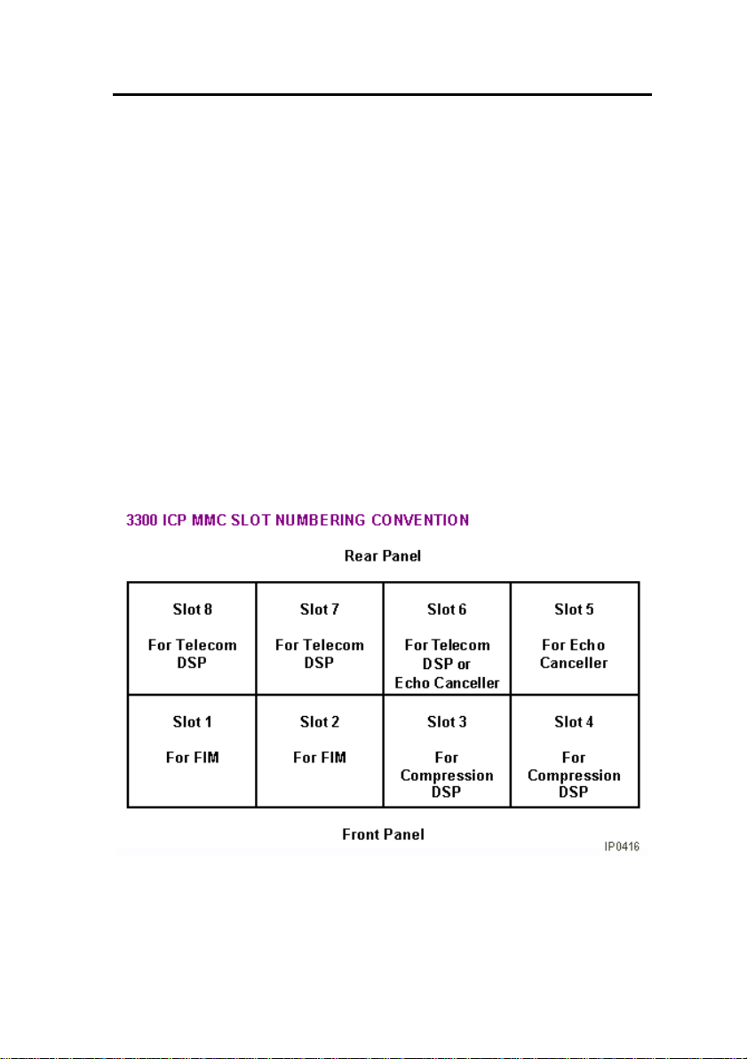
Configurations
There are several configuration options for the 3300 ICP:
• 250 user system without compression
• 250 user system with 32 compression channels
• 250 user system with 64 compression channels
• 700 user system without compression
• 700 user system with 32 compression channels
• 700 user system with 64 compression channels.
The following top view diagram shows the MMC/A slot numbering
convention. The diagram also indicates the type of MMC module
that will be used in a particular slot. Slots 1 through 4 allow
connectors to protrude through the front panel.
- 13 -
Page 22
3300 ICP Technician’s Handbook – Release 3.2
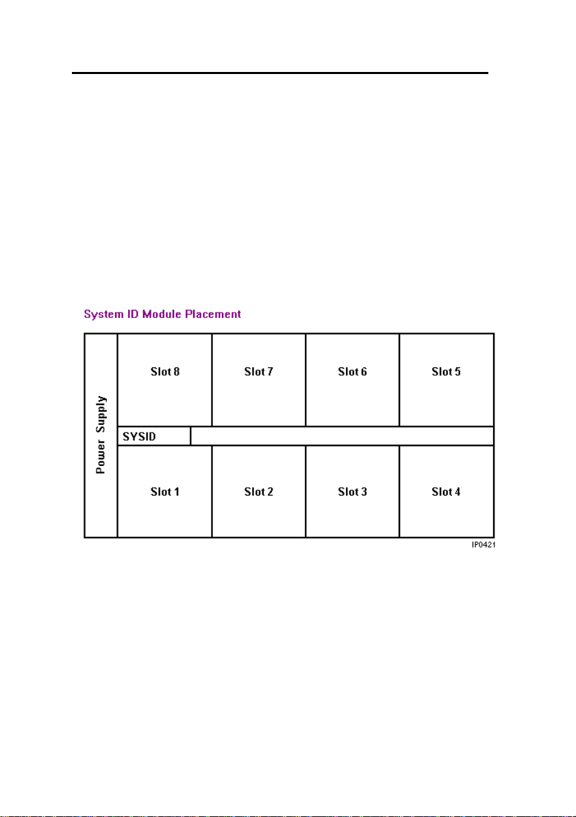
Install the System ID Module
The system ID module is shipped with the software. You must
install the system ID module in the 3300 ICP controller. The module
contains a unique identifier that the system reads on start-up.
To install the System ID Module:
1. Remove the cover.
2. Press firmly to seat the module on the board. Placement is
between MMC 1 (the Dual FIM) and MMC 8 (the DSP). The
module will cover the 'MMC 8' text printed on the board.
3. Replace the cover.
- 14 -
Page 23

3300 ICP Technician’s Handbook – Release 3.2
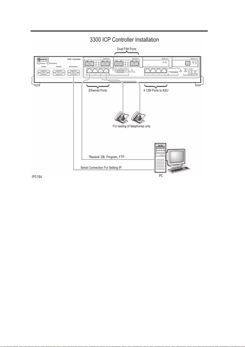
Install the 3300 Controller
To install the 3300 Controller:
1. Install the System ID Module.
2. Set up a serial connection between the 3300 Configuration Tool
PC and the Maintenance (RS-232) port on the 3300 Controller.
Baud rate - 9600, Data bits - 8, Parity - None Stop bits - 1, Flow
control - None.
3. Set up an Ethernet connection between the 3300 Controller and
the 3300 Configuration Tool PC (a standard LAN cable from an
RJ-45 connector on the 3300 Controller L2 switch to the PC
NIC).
Note: You can connect IP telephones to the 3300 Controller
through L2 switch external ports, for testing only, after
installation of the database and configuration. IP Phones
require a configured DHCP server.
- 15 -
Page 24
3300 ICP Technician’s Handbook – Release 3.2
- 16 -
Page 25

3300 ICP Technician’s Handbook – Release 3.2
Configure the Controller
Note: Before you begin, you should review the LAN and WAN
guidelines and plan the network . Complete the Ins ta lla tio n
Planner. You will need to know the IP addresses reserved by
the customer for the 3300 ICP Controller (one for the RTC and
one for the E2T) and for the IP Phones.
Time: The initial power-up and the reset in this procedure will
each take 15 to 20 minutes.
To complete the installation of the Mitel Networks 3300 ICP:
1. Connect power to the 3300 Controller. The controller will come
up, in 15 to 20 minutes, with factory-installed software.
2. To check connections between the 3300 Controller and the PC:
PING the 3300 Controller IP address
FTP to the 3300 Controller IP address
Go to the 3300 Controller URL address (http://192.168.1.2).
3. Launch browser to login to the System Administration Tool
(http://192.168.1.2 -- username is system, password is
password).
4. Optional. Install the Mitel Networks 3300 Configuration Tool on
your PC. Use the Configuration Tool to reset the default
database, import the .csv file, and make programming changes.
Refer to the 3300 Configuration Tool online help for detailed
instructions.
5. Enable the options in the License and Option Selection form
and reboot.
6. Program the system by using the System Administration Tool or
restore a database.
7. Configure the DHCP Server with IP addresses provided by the
customer. Refer to the Note and default settings table following
this procedure.
8. If you are using an external DHCP Server, disable the internal
DHCP Server.
9. Perform a Backup.
- 17 -
Page 26

3300 ICP Technician’s Handbook – Release 3.2
10. Reboot the system.
11. Set the 3300 Controller (RTC) IP address through a
communication program.
12. Install the other units as described in the System Installation
Overview.
13. As the final step, connect the 3300 Controller to the LAN.
Note: You may use the internal or an external DHCP Server.
The controller is shipped with the DHCP server Enabled. Use
DHCP reservations against the MAC address for the E2T.
Internal DHCP Server default settings - shipped enabled
TFTP Server 066 192.168.1.2
TFTP BootFile 067 /sysro/E2T8260
IP Phone TFTP Server 128 192.168.1.2
MN330 (RTC) IP Address 129 192.168.1.2
Mitel IP Phone DHCP Server 130 MITEL IP PHONE
Range Start
End
192.168.1.20
192.168.1.24
Set the 3300 Controller IP Address
To set the 3300 Controller IP address:
1. Establish a serial connection from the 3300 Configuration Tool
PC (or any PC equipped with a communications program) to
the Maintenance Port on the 3300 Controller.
2. Launch the communication program.
3. Set the RS-232 communication parameters:
Baud rate - 9600
Data bits - 8
Parity - None
Stop bits - 1
Flow control - None
4. Connect AC power to the 3300 Controller.
- 18 -
Page 27

3300 ICP Technician’s Handbook – Release 3.2
5. Press the Reset button on the 3300 Controller with a small
pointed object.
6. Wait for the "Press any key to stop auto-boot" message and
then press a key.
7. At VxWorks Boot type c and then press Enter.
Press Enter after you enter required text. For all other fields,
(displayed in grey text, for information only) accept the default
value or leave blank.
boot device: ata=0,0 (Boot device is Disk)
unit number: 0 (default, leave at 0, not used)
processor number: 0 (default, leave at 0, not used)
host name: (optional)
file name: /sysro/Rtc8260 (boot location and file name)
inet on ethernet (e): 134.199.63.11:ffffff00 (example RTC IP
and subnet mask)
Note: Type the IP address and subnet mask (in hexadecimal
format for the end user's site (i.e. ffffff represents
255.255.255.00).
inet on backplane (b):
host inet (h):
gateway inet (g): 134.199.63.251 (example Router (Gateway)
address)
Note: Enter the IP address of the end user's gateway for the
3300 Controller.
user (u): ftp (must be ftp for Release 3.1)
ftp password (ftp) (blank = @):
flags (f): 0x0 (a fixed IP address (0x40 is used on E2T for
DHCP)
target name (tn):
startup script (s):
other (o): motfcc (other device, E2T using Network to boot from)
8. Press the Reset button on the 3300 Controller.
9. Remove the Serial connection. The system will return to service
in about 10 to 15 minutes.
Note: It may be helpful to leave the serial connection in place to
capture any potential errors.
- 19 -
Page 28

3300 ICP Technician’s Handbook – Release 3.2
Network Services Units
Install the 3300 Universal NSU
To install the 3300 Universal NSU:
1. Set DIP switch #6 for Network or Line termination mode. The
default is network termination mode. Refer to Universal NSU
DIP Switch Settings.
2. Establish a fiber connection from the fiber port on the NSU to
the fiber port on the 3300 Controller.
3. Connect the NSU L0 and/or L1 port to the remote system (the
PSTN or another system) by using Category 5 cable.
4. Connect power to the NSU.
Note: The Ethernet port is used for FTP upgrades.
Note: The cable for the CIM ports must be an Ethernet
crossover cable.
Install for PRI/Q.SIG
To install and configure the 3300 Universal NSU as a PRI/QSIG
variant:
1. Install a Direct Connection Device Driver on a computer.
2. Create a Dial-up Network connection on your computer.
3. Connect the computer to the 3300 Universal NSU.
4. Use the IMAT Tool to complete required PRI configuration.
5. Connect the 3300 Universal NSU to the ISDN network.
Connecting a Laptop Computer to the NSU
To connect a computer to the NSU:
1. Install IMAT. From the 3300 Software CD-ROM, run
Tools/IMAT/Disk1/setup.exe.
2. Use a straight through serial cable for a direct connection.
- 20 -
Page 29

3300 ICP Technician’s Handbook – Release 3.2
3. Use a null modem adapter if connecting to the card through a
modem.
4. If you have not already done so on the laptop computer, install
a Direct Connect modem type. You may also wish to install a
modem for remote connection.
5. On the laptop, create a new Dial-up Networking entry.
Create a Modem Connection
1. Install the modem following the manufacturer's installation
instructions.
2. In the Modem Properties/Advanced Settings window - Turn off
error control - Turn on flow control and select Hardware.
Install Direct Connect Device Driver
By default, Windows does not support a direct cable connection.
You must add a device driver. Windows takes the information from
a Mitel file and creates the driver called NT Direct Connection.
Refer to detailed installation and configuration instructions for:
• Direct Connection Device Driver for Windows 95 and Windows
98
• Direct Connection Device Driver for Windows 2000 Professional
Driver for Windows 95 and Windows 98
To install and configure the Direct Connection Device Driver for
Windows 95 or Windows 98:
1. On the Start menu, point to Settings, and then click Control
Panel.
2. Double-click the Modems icon.
3. In the Modem Properties window, click Add.
4. In the Install New Modem screen, click Other.
5. Select Don’t detect my modem, I will select from a list. Click
Next.
6. Click Have Disk.
- 21 -
Page 30

3300 ICP Technician’s Handbook – Release 3.2
7. Type c:\Program Files\Mitel\Imat in the Copy manufacturer's
files from field and click OK.
8. On the Install from Disk window, click OK.
9. Click Next to select the NT Direct Connection.
10. Select COM 1 or COM 2, and then click Next.
11. Click Finish.
12. In the Modem Properties window, select NT Direct
Connection, and then click Properties.
13. Set the following parameters:
- Maximum speed: 38400
- Check: only connect at this speed
- Data bits: 8
- Parity: none
- Stop bits: 1
- Mode: auto answer In the Advanced Settings window, do the
following for a direct connect cable:
- Turn off: error control
- Turn off: flow control
14. Click OK and close the Control Panel window.
Driver for Windows 2000
To install and configure Direct Connection Device Driver for
Windows 2000 Professional:
1. On the Start menu, point to Settings, then click Control Panel.
2. Double-click Phone and Modem Options icon.
3. Select the Modem tab.
4. Click Add.
5. Click Other on the Install New Modem screen.
6. Select Don’t detect my modem, I will select it from a list and
click Next.
7. In the Modems field, select Communications cable between
two computers, then click Next.
8. Select COM 1 or COM 2, then click Next.
- 22 -
Page 31

3300 ICP Technician’s Handbook – Release 3.2
9. Click Finish.
10. T he COM Port will be displayed in the Phone and Modem
Options window, Modems tab. Select the COM Port and then
click Properties.
11. From the Maximum Port Speed drop-down menu, select
38400.
12. In the Communications cable between two computers, select
the Advanced tab, and then click Change Default
Preferences.
13. From the Port speed drop- d o wn list se lec t 38400, and then
from the Flow control drop-down list select None.
14. Select the Advanced tab. From the drop-down menus, set the
fields as follows: - Data bits: 8 - Parity: none - Stop bits: 1
15. Click OK and close the Control Panel window.
Create a Dial-up Network Connection
Typically, you will want to follow this procedure twice to create two
Dial-up Networking connections, one for on-site direct access, and
one for remote modem access.
Refer to detailed instructions for:
• Dial-up Networking Connection for Windows 95 or Windows 98
• Dial-up Network connection for Windows 2000 Professional
Dial-up Connection for Windows 95 or Windows 98
To create a dial-up networking connection for Windows 95 or
Windows 98:
1. On the Start menu, point to Programs, point to Accessories,
and then click Dial-Up Connections.
2. Double-click Make New Connection.
3. Enter an appropriate name for the connection (for example,
Direct for direct connections, Remote or a customer’s name for
remote connections) and click Next. Note: If you are creating a
direct connection, make sure NT Direct Connection is listed in
the drop-down list in the Make a New Connection window.
- 23 -
Page 32

3300 ICP Technician’s Handbook – Release 3.2
4. Enter an Area Code and Telephone Number and select a
Country Code from the drop-down list. Click Next. Note: Even
though it is not needed for a direct connection , Windows
requires that you enter this information.
5. Click Finish.
6. Right-click your new connection icon and click Properties.
7. Click Configure. Ensure the fields are set as follows:
- Data bits: 8
- Parity: none
For a direct connection:
- Maximum speed: 38400
- Check: only connect at this speed
- Select wait for dial tone before dialing
- Select cancel the call time at 60 sec.
- Click Advanced and turn off error control and flow control
For a remote connection:
- Stop bits: 1
- Click Advanced and turn on error control and select Compress
data.
- Turn on flow control and select Hardware.
8. Click OK.
9. Select Server Types tab and make sure that PPP: Windows,
WindowsNT3.5, Internet or PPP:Internet appears in the Type of
Dial-Up Server field.
10. In the Advanced Options field, sele ct Log onto Network and
Enable software compression .
11. Make sure that only TCP/IP is selected in the Allowed network
protocols field.
12. Select the Scripting tab and enter c:\program
files\mitel\Imat\pridun.scp for a 3300 Universal NSU c:\program
files\mitel\Imat\r2dun.scp for a 3300 R2 NSU.
13. Click OK.
Dial-up Connection for Windows 2000
To create a dial-up networking connection for Windows 2000
Professional:
- 24 -
Page 33

3300 ICP Technician’s Handbook – Release 3.2
1. On the Start menu, point to Programs, point to Accessories,
click Communications, and then click Dial-Up Connections.
2. Double click Make New Connection, and then click Next.
3. Select Dial-up to the Internet, and then click Next.
4. Select I want to set up my Internet connection manually, or I
want to connect through a local area network (LAN). Click
Next.
5. Select I connect through a phone line and a modem, and
then click Next.
6. Use the COM Port that has been configured as a NULL Modem
connection: 38400, 8, none, 1.
7. In the Choose Modem box, from the drop-down list select
Communications cable between 2 computers. Click Next.
8. Clear the box Use area code and dialing rules, and then click
Advanced.
9. For the Connection type, select PPP (Point to Point Protocol).
For the Logon procedure, select Use logon script, and then click
Browse. Select pridun.scp. Click OK, and then click Next.
10. In the Internet account logon information box, leave the
username and password fields blank and then click Next.
11. Dialog boxes appear that warn you that you will not be able to
connect to your Internet service provider without your user
name and your password. Disregard these warnings and click
Yes on these boxes to continue.
12. Enter the Connection name, and then click Next.
13. In the box to set up an Internet mail account, select No, and
then click Next.
14. De-select the option to connect to the Internet immediately,
then click Finish.
15. In the Network and Dial-up Connections window, right-click on
the new DUN connection, point to Properties, then click
Configure.
- 25 -
Page 34

3300 ICP Technician’s Handbook – Release 3.2
16. From the Maximum speed (bps) drop-down list, select 38400
for the baud rate.
17. Click OK until you exit the windows.
3300 Universal NSU DIP Switch Settings
Hybrid Port DIP Switch Settings
DIP
Switch
1 Tx Ground Ground when down; floating when up.
2 Rx Ground Ground when down; floating when up.
3 Impedance selector #1 120 ohm (enabled when down)
4 Impedance selector #2 100 ohm (enabled when down)
5 Impedance selector #3 75 ohm (enabled when down)
6 LT/NT selector Up for NT; down for LT.
PRI/T1 Mode Connector DIP Switch Settings
Impedance 1 Tx Gnd 2 Rx
100 Up Up Up Down Up Down
E1/MF-R2 Mode/Connector DIP Switch Settings
BNC
Adapt.
Req’d
No 120 Up Up Down Up Up Up
No 120 Up Up Down Up Up Down
Yes 75 Note Note Up Up Down Up
Yew 75 Note Note Up Up Down Down
Note: Site-dependant – normally Tx is grounded and Rx is not grounded, but
that depends on which remote connection is grounded.
Use Notes
3 I #1 4 I #2 5 I #3 6
Gnd
Imp. 1
Tx
Gnd
2
Rx
Gnd
3
120
ohm
4
100
ohm
5
75
ohm
LT/NT
6
LT/NT
- 26 -
Page 35

3300 ICP Technician’s Handbook – Release 3.2
Install the 3300 R2 NSU
To install and configure the 3300 R2 NSU:
1. Set the DIP switches for the protocol and site installation. The
default configuration of the DIP switches will support T1
protocols in network term inatio n m ode.
2. Establish a fiber connection from the fiber port on the NSU to
the fiber port on the 3300 Controller.
3. Connect the NSU L0 and/or L1 port to the remote system (the
PSTN or another system).
4. Install a Direct Connection Device Driver on a PC. Refer to
Install the 3300 Universal NSU for details.
5. Create a Dial-up Network connection on the PC. Refer to Install
the 3300 Universal NSU for details.
6. Connect the computer to the 3300 R2 NSU.
7. Use the IMAT Tool to complete the required configuration.
8. Connect the 3300 R2 NSU to the PSTN network.
9. Connect the 3300 R2 NSU to the 3300 Controller.
10. Connect power to the NSU.
Connections
Connect the computer to the 3300 R2 NSU
To connect the computer to the 3300 R2 NSU:
1. Connect the serial cable from the computer's COM port to the
3300 R2 NSU 9-pin serial port.
2. On the File menu, click Connect to Remote Site.
3. In the Dial-Up Entry box, select the <name> you entered for
the connection when creating the dial-up connection. (See DialUp Networking Connection.) Note: The 3300 R2 NSU does not
require a password.
4. Ensure that PRI CARD is selected under Remote ISDN
System.
- 27 -
Page 36

3300 ICP Technician’s Handbook – Release 3.2
5. Click Connect.
6. In the Connected to remote site window, click OK.
Note: A networked computer running Win95/98 has difficulties
communicating using Dial-up Networking. It is strongly
suggested that a non-networked computer be used.
Connect the 3300 R2 NSU to the 3300 Controller
A fiber connection originates from a fiber interface module (FIM)
port on the front of the 3300 Controller and is terminated on the FIM
port of the digital trunking 3300 R2 NSU.
The 3300 R2 NSU is connected to the Public Switched Telephone
Network (PSTN) termination point from the L0 port with CAT 5
cable.
MF-R2 Port DIP Switch Settings
Switch Use Default Notes
1 Tx Ground Up Tx shield ground when
down
2 Rx Ground Up Rx shield ground when
down
3 Impedance selector #1 Up 120 ohm
4 Impedance selector #2 Up 100 ohm
5 Impedance selector #3 Up 75 ohm
6 LT/NT selector Up Up for NT, down for LT
- 28 -
Page 37

3300 ICP Technician’s Handbook – Release 3.2
E1/MF-R2 Mode/Connector DIP Switch Setting
BNC
Adapt
Req’d
No 120 NT Up Up Down Up Up Up
No 120 LT Up Up Down Up Up Down
Yes 75 NT Note Note Up Up DownUp
Yes 75 LT Note Note Up Up DownDown
Note: Site dependent - normally Tx is grounded and Rx is not grounded,
but that depends on which remote connection is grounded.
Imp.
LT/NT
Mode1 Tx
Gnd
2
Rx
Gnd
3
120
ohm
4
100
ohm
5
75
ohm6LT/NT
Install the 3300 BRI NSU
To install the 3300 BRI NSU:
1. Configure the 3300 Controller E1 DPNSS on the 3300
Universal NSU that will be used to connect to the 3300 BRI
NSU.
2. Program the BRI-specific requirements for the E1 DPNSS
interface.
3. Set up the maintenance PC.
4. Complete the 3300 BRI NSU programming.
5. Connect power to the NSU.
Note: The 3300 BRI NSU is set for 75 ohms impedance when
connected to a digital trunking NSU running E1 DPNSS. The
3300 Universal NSU is also set for 75 ohms impedance.
Note: A Category 5 connection from the 3300 BRI NSU E1 port
to a 3300 Universal NSU that is running E1 DPNSS. E1
connections as TX and RX pairs in RJ-45. Option to ground one
side of TX and or RX (using DIP switch) to use with coax
adapter.
- 29 -
Page 38

3300 ICP Technician’s Handbook – Release 3.2
Note: The 3300 BRI NSU is connected to an appropriate device
(such as a PSTN or ISDN device) from a 25-pair Amphenol
connector.
Setting Up the Maintenance PC
To install, configure, and maintain the 3300 BRI NSU, you must
connect it to a maintenance computer. The computer must be
running DOS and have a communications program (such as
ProComm Plus ©) installed.
To connect a maintenance PC to the 3300 BRI NSU:
1. Using the RJ45 to 9-pin D-type MMI cable, connect the RS-232
port on the 3300 BRI NSU to COM port 1 or 2 on the PC.
2. Set up the communications program on COM port 1 or 2 with
the following parameters: 9600 baud, 8 data bits, no parity, 1
stop bit, ASCII character set, and XON/XOFF flow control.
3300 NSU Pin Allocations
T1 and E1 Connector Allocation
Signal Name RJ-45 Connector Pin
RXRING 1
RXTIP 2
Not used 3
TXRING 4
TXTIP 5
Not used 6
Not used 7
Not used 8
- 30 -
Page 39

3300 ICP Technician’s Handbook – Release 3.2
RS-232 Maintenance Connector Allocation
Signal Name RJ-45 Connector Pin
DTR (data terminal ready)
DCD (data carrier detector)
RXD (receive data) 2
TXD (transmit data) 3
DTR (data terminal ready) 4
GND 5
Not used 6
RTS (ready to send) 7
CTS (clear to send) 8
Not used 9
BRI Connector Allocation
T1 1
T2 2
T3 3
T4 4
T5 5
T6 6
T7 7
T8 8
T9 9
T10 10
T11 11
T12 12
T13 13
T14 14
T15 15
R1 26
R2 27
1
- 31 -
Page 40

3300 ICP Technician’s Handbook – Release 3.2
BRI Connector Allocation
R3 28
R4 29
R5 30
R6 31
R7 32
R8 33
R9 34
R10 35
R11 36
R12 37
R13 38
R14 39
R15 40
NSU Chaining
NSU chaining refers to the physical connection of two NSUs
together, on one fiber interface, from the Controller. BRI NSUs may
not be chained.
To connect two NSUs to the Controller:
1. Connect the first NSU to the controller through a fiber
connection from the fiber port on the NSU to the fiber port on
the 3300 Controller.
2. Using a CAT5 crossover cable make a connection from CIM2
on the first NSU to CIM1 on the second NSU.
3. Connect power to the NSU.
Note: The first NSU must have the Message Link dip switch set
to 1, up. The second NSU must have the Message Link dip
switch set to 2, down.
- 32 -
Page 41

3300 ICP Technician’s Handbook – Release 3.2
Analog Services Units
Install the 3300 Universal ASU
Before you begin, ensure that there is a free CIM port on the 3300
Controller.
To install the 3300 Universal ASU:
1. Mount the 3300 Universal ASU in the 19-inch rack (if
applicable).
2. Connect the supplied Cross-over Category 5 cable with RJ-45
connector to the CIM port on the 3300 Universal ASU and a
free CIM port on the 3300 Controller. Note that up to four ASUs
can be connected to the 3300 Controller.
3. Complete telephony cabling.
4. Complete programming.
5. Connect power to the 3300 Universal ASU. CIM LEDs will be
on once the CIM link synchronizes. The 3300 Controller will
detect the 3300 Universal ASU, and the application software
will download and start immediately.
Install the 3300 ASU
Before you begin, ensure there is a free CIM port on the 3300
Controller.
To install the 3300 ASU:
1. Mount the 3300 ASU in the 19-inch rack (if applicable).
2. Connect the supplied Cross-over Category 5 cable with RJ-45
connector to the CIM port on the 3300 ASU and a free CIM port
on the 3300 Controller. Up to four ASUs can be connected to a
3300 Controller.
3. Power up the 3300 ASU. CIM LEDs will be on once the CIM link
synchronizes. The 3300 Controller will detect the 3300 ASU,
and the application software will download and start
immediately.
4. Complete telephony cabling.
- 33 -
Page 42

3300 ICP Technician’s Handbook – Release 3.2
5. Complete programming.
3300 ASU and Universal ASU Pin Allocations
CIM Connector Pin Allocations
Pin Signal Pin Signal
1 RX+ 5 Not Used
2 RX- 6 TX3 TX+ 7 Not Used
4 Not Used 8 Not Used
Note: The 3300 Universal ASU connects to the 3300 Controller over a
Category 5 Universal Twisted Pair (UTP) cross-over cable through a CIM
interface. The Category 5 cable is of the same type used for Ethernet
connections and within the cable twisted pairs are arranged as: 1,2: 3,6;
4,5; 7,8. Each tied pair is connected to a 75 ohm resistor. The 3300
Universal ASU can be located up to 30 meters (98.4 feet) away from the
3300 Controller. The interface employs a single standard 8-pin modular
jack consisting of 2 balanced signal pairs and is located on the front of
the unit.
25 pair Connector Pin Allocations
Note: Connection of the Tip and Ring (A and B) leads of the ONS lines
and LS trunk circuits are through a 25 pair female D-type connector.
Pin Signal Pin Signal
1 ONS Tip 1 26 ONS Ring 1
2 ONS Tip 2 27 ONS Ring 2
3 ONS Tip 3 28 ONS Ring 3
4 ONS Tip 4 29 ONS Ring 4
5 ONS Tip 5 30 ONS Ring 5
6 ONS Tip 6 31 ONS Ring 6
7 ONS Tip 7 32 ONS Ring 7
8 ONS Tip 8 33 ONS Ring 8
9 ONS Tip 9 34 ONS Ring 9
- 34 -
Page 43

3300 ICP Technician’s Handbook – Release 3.2
25 pair Connector Pin Allocations
Note: Connection of the Tip and Ring (A and B) leads of the ONS lines
and LS trunk circuits are through a 25 pair female D-type connector.
Pin Signal Pin Signal
10 ONS Tip 10 35 ONS Ring 10
11 ONS Tip 11 36 ONS Ring 11
12 ONS Tip 12 37 ONS Ring 12
13 ONS Tip 13 38 ONS Ring 13
14 ONS Tip 14 39 ONS Ring 14
15 ONS Tip 15 40 ONS Ring 15
16 ONS Tip 16 41 ONS Ring 16
17 LS Tip 1 42 LS Ring 1
18 LS Tip 1-1 43 LS Ring 1-1
19 LS Tip 2 44 LS Ring 2
20 LS Tip 1-2 45 LS Ring 1-2
21 LS Tip 3 46 LS Ring 3
22 LS Tip 1-3 47 LS Ring 1-3
23 LS Tip 4 48 LS Ring 4
24 LS Tip 1-4 49 LS Ring 1-4
25 N/C 50 N/C
- 35 -
Page 44

3300 ICP Technician’s Handbook – Release 3.2
Music on Hold Connector Pin Allocations (Universal ASU only)
Pin Signal Pin Signal
1 Tip 1 5 Ring 3
2 Ring 1 6 Ring 2
3Tip 27Tip 4
4 Tip 3 8 Ring 4
Note: The four MOH tips & rings occupy an 8 pin female modular jack
located on the rear panel.
Note: Only one port is supported through software on the system.
Paging Connector Pin Assignments (Universal ASU only)
Pin Signal Pin Signal
1 Tip 1 5 Ring 2
2 Ring 1 6 Ring 1-1
3 Tip 1-1 7 Tip 1-2
4 Tip 2 8 Ring 1-2
Note: The paging port employs a single standard 8-pin modular RJ-45
jack located on the rear panel.
Each paging port has a tip/ring pair for audio and a second tip/ring pair
designated tip1/ring1 contact closures for zone control.
- 36 -
Page 45

3300 ICP Technician’s Handbook – Release 3.2
Peripheral Unit
Overview of the Peripheral Unit Installation
To install a Peripheral Unit:
1. Unpack, position, and ground the Peripheral Unit.
2. Check the card layout.
3. Connect the fiber cable to the node.
4. Check the grounding.
5. Install the power converter.
6. Install the Peripheral Interface cards.
7. Cable the node to the MDF.
8. Power up the Peripheral Unit.
Note: For information about removing and replacing the front
panel of the cabinet, see Front Panels in Install Upgrades and
FRUs.
Proceed to Installing a DSU Node, Installing a SUPERSET HUB, or
return to System Installation Overview.
Unpack, Position, and Ground the Peripheral Unit
To unpack, position, and ground the node:
CAUTION: Power must not be applied to the Peripheral Unit
until you have installed the ground cable.
1. Unpack the peripheral node.
2. Check the contents against the packing list.
3. Visually inspect the node and attached equipment for damage.
Repack and return any damaged equipment.
4. Position the node.
5. Connect an external ground to the ground terminal on the rear
panel of the peripheral cabinet. Refer to the Safety Instructions
- 37 -
Page 46

3300 ICP Technician’s Handbook – Release 3.2
for detailed grounding requirements. These instructions are
packaged with each system.
Peripheral Unit Card Layout
Typically, a peripheral cabinet is shipped with the peripheral switch
controller (PSC) card and Fiber Interface Module (FIM) installed. If
these cards were not shipped in the cabinet, install them as Field
Replaceable Units (FRUs). You must install and cable the FIM
before you install the peripheral switch controller card and power
converter (see Peripheral Unit FRUs section).
The cards in the peripheral unit should be installed in the following
configuration:
Slot Number Card Type
1 to 12 Peripheral Interface card
13, 14, 15 (combined) Power Converter
16 Peripheral Switch Controller (PSC)
17 Fiber Interface Module (FIM)
Note: If you are installing an expanded Peripheral Unit, or
expanding an existing one, the card layout will be different
depending on if the cabinet is used as the master or slave of
the peripheral pair.
- 38 -
Page 47

3300 ICP Technician’s Handbook – Release 3.2
Connect Fiber Cable to the Peripheral Unit
The fiber optic cable connects the FIM in the 3300 Controller to the
FIM in the Peripheral Unit.
To connect the fiber optic cable to the FIM in the peripheral node:
1. Review the guidelines for handling fiber optic cable.
2. Route the fiber optic cable through the cable port at the rear of
the peripheral cabinet into the cabinet. Extend the fiber cable
approximately 30 cm (1 ft) beyond the front of the cabinet.
3. Install a short piece of nylon spiral wrap over the cable at the
point where the cable exits the rear of the cabinet.
4. Close the sliding cable port door. Ensure that the door closes
on the nylon spiral-wrapped section of fiber cable.
- 39 -
Page 48

3300 ICP Technician’s Handbook – Release 3.2
5. Remove the plastic dust caps from the fiber optic cable and the
connector ferrules on the FIM faceplate.
6. Plug the fiber connectors into the connectors on the FIM
faceplate. The fiber connectors have a small key that must be
aligned with a slot on the FIM connectors. Lock each connector
into position by pushing the metal collar forward and clipping it
onto the FIM connector.
Peripheral Unit Grounding
CAUTION: Ensure that the grounding meets the requirements
specified in the Safety Instructions. These instructions are
packaged with each system.
WARNING: Danger to personnel and/or equipment damage
could result if the cabinet is not powered off.
To check the grounding:
1. Ensure that the power switch (S1) on the power distribution unit
(PDU) is set to the off (0) position and that the switch on the
power converter faceplate is set to the off (0) position.
2. Attach the anti-static wrist strap to your wris t.
3. Slide the installed circuit cards forward slightly so that the card
connectors are not in contact with the cabinet backplane. Leave
the power converter installed.
4. Remove the anti-static wrist strap.
5. Plug the external power cable from the AC commercial power
supply into the power-input plug on the power distribution unit
(PDU).
6. Disconnect the protective earth wire from the protective earth
ground stud on the rear of the cabinet.
7. Using a digital multimeter, measure the AC potential between
the protective earth wire (build in g ground) and the pr otective
earth ground stud. A voltage reading of less than 1 VAC is
acceptable. To prevent damage to the multimeter, set it to the
maximum AC scale, then reduce the setting gradually to the 10
VAC range.
- 40 -
Page 49

3300 ICP Technician’s Handbook – Release 3.2
8. If the potential is greater than 1 VAC, recheck the ground
connections and repeat the measure.
9. If the reading still exceeds 1 VAC, the building ground is
unacceptable. Connect the protective earth wire to a new
building ground and repeat the steps 7 through 9 until you have
an acceptable AC potential. WARNING: Do not continue until
you have a potential of 1 VAC or less between the building
ground and the protective earth ground stud. Otherwise,
personal injury and/or equipment damage may result.
10. Reconnect the protective earth wire to the protective earth
ground stud and attach the anti-static wrist strap to your wrist.
11. Slide the installed circuit cards back into contact with the
cabinet backplane. Ensure that each card is fully inserted in its
slot.
Power Converter
To install an AC power converter:
WARNING: Danger to personnel and/or equipment damage
could result if the cabinet is not powered off during installation
of the AC power converter.
1. At the rear of the cabinet, remove the two screws that fasten
the internal AC power cord access cover plate to the backplane,
and remove the cover plate (see figure).
2. Ensure that the switch on the power converter faceplate is set
to off (0).
3. Install the power converter in slots 13 through 15.
4. Plug the internal AC power cord from the power distribution unit
(PDU) into the power converter through the access cutout in the
backplane.
5. Replace the internal AC power cord access cover plate over the
access cutout in the backplane, and replace the two screws.
- 41 -
Page 50

3300 ICP Technician’s Handbook – Release 3.2
- 42 -
Page 51

3300 ICP Technician’s Handbook – Release 3.2
Install Peripheral Interface Cards
To install the Peripheral Interface cards:
CAUTION: To prevent static damage to electrical components,
ensure that the system is grounded before you install the
cards. Whenever you handle circuit cards, wear an anti-static
strap.
1. Install the peripheral switch controller card in slot 16.
2. Set the E&M Trunk Card settings and the OPS Line Card
Message Waiting Switches in the Peripheral Unit Specifications
section.
3. Install the Peripheral Interface cards. Refer to Install a Circuit
Card in "Install Upgrades and FRUs" for circuit card installation
procedures.
Cable the Unit to the MDF
Cable the lines and trunks from the Peripheral Unit to the Main
Distribution Frame (MDF) by using the Peripheral Interface Cabling
Tables.
About Peripheral Interface Cabling
Peripheral equipment (e.g., stations, SUPERSET telephones,
trunks) is connected to the relevant interface circuits of the system
via a cross-connect field. Peripheral Interface cards, situated in
slots 1 through 12, are connected to the cross-connect field by a
maximum of eight 25-pair cables (customer-supplied) per
Peripheral Unit. Cables terminate at the node on 50-pin plugs, J1
through J8, with the number of cables being dependent on the
quantity and type of interface cards installed in the node.
Plugs J1 through J8 are hardwired to backplane connectors in slots
1 through 12 to form four slot groups, each comprising three
adjacent cards and each associated with a pair of plugs. T wo
adjacent slot groups are shown in Backplane Connector
Arrangements. The circuits of interface cards contained in a slot
group are evenly distributed to the relevant pair of plugs, such that,
half the circuits of each card in a group are connected to the odd-
- 43 -
Page 52

3300 ICP Technician’s Handbook – Release 3.2
numbered plug and half to the even-numbered plug. Peripheral
Wiring (Backplane) details the hardwire connections between one
slot group and the associated plugs. The wiring sequence is
identical for the remaining three slot groups.
Cable jacks (P1 through P8), are customer-supplied and should be
labeled at time of installation. P1 through P8 are secured to J1
through J8 with hook and loop type fasteners. Equipment that is
external to the system (i.e., system to cross-connect field cables
and cross-connect field hardware) is not supplied by MITEL.
Therefore, the type of equipment used and the layout of the crossconnect field cables is at the discretion of the installation company.
Installation information for such equipment must be obtained from
the equipment manufacturer.
Backplane Connector Arr ang ements
- 44 -
Page 53

3300 ICP Technician’s Handbook – Release 3.2
Peripheral Wiring (Backplane)
Peripheral Interface Cabling Tables
Use the tables to cable the Peripheral Unit card connectors to the
main distribution frame.
Note: When cabling the SX-2000 MICRO LIGHT node
connectors, use the cabling tables that correspond to the
Peripheral Interface card slot in the node.
Cable Connectors
Connectors for customer supplied 25-pair cables terminating on
peripheral backplane (to MDF) and SFT unit (to MDF) use AMP
Champ or equivalent cable connectors:
• 50-pin RS (receptacle - screw lock)
• female
• screw lock
- 45 -
Page 54

3300 ICP Technician’s Handbook – Release 3.2
• 90 tapered slide-on hood.
USOC Connector Pin Designations
The USOC connector numbers are:
• RJ2I X for CO Trunks
• RJ2EX for 2-wire E&M Trunks
• RJ2FX for 4-wire E&M Trunks
• RJ2GX for 4-wire E&M Trunks
• RJ2HX for 4-wire E&M Trunks.
USOC Connector Pin Designations
Pin Color Code RJ21X RJ2EX RJ2GX RJ2FX RJ2HX
26 W/BL T T T T T
1BL/W R R R R R
27 W/O T E T1 E T1
2 O/W R M R1 SG R1
28 W/G T T E M E
3G/W R R M SB SG
29 W/BR T E T T M
4BR/W R M R R SB
30 W/S T T T1 E T
5S/W R R R1 SG R
31 R/BL T E E M T1
6BL/R R M M SB R1
32 R/O T T T T E
7O/R R R R R SG
33 R/G T E T1 E M
8 G/R R M R1 SG SB
34 R/BR T T E M T
9BR/R R R M SB R
35 R/S T E T T T1
10 S/R R M R R R1
- 46 -
Page 55

3300 ICP Technician’s Handbook – Release 3.2
Pin Color Code RJ21X RJ2EX RJ2GX RJ2FX RJ2HX
36 BK/BL T T T1 E E
11 BL/BK R R R1 SG SG
37 BK/O T E E M M
12 O/BK R M M SB SB
38 BK/G T T T T T
13 G/BK R R R R R
39 BK/BR T E T1 E T1
14 BR/BK R M R1 SG R1
40 BK/S T T E M E
15 S/BK R R M SB SG
41 Y/BL T E T T M
16 BL/Y R M R R SB
42 Y/O T T T1 E T
17 O/Y R R R1 SG R
43 Y/G T E E M T1
18 G/Y R M M SB R1
44 Y/BR T T T T E
19 BR/Y R R R R SG
45 Y/S T E T1 E M
20 S/Y R M R1 SG SB
46 V/BL T T E M T
21 BL/V R R M SB R
47 V/O T E T T T1
22 O/V R M R R R1
48 V/G T T T1 E E
23 G/V R R R1 SG SG
49 V/BR T E E M M
24 BR/V R M M SB SB
50 V/S -- -- SPARE -- -25 S/V -- -- SPARE -- --
- 47 -
Page 56

3300 ICP Technician’s Handbook – Release 3.2
Card Connections to Cross-Connect Field
The following tables show the “pin-out” signals of the interface
cards as they appear on J1 through J8. The following abbreviations
are used in the tables:
ONS L C: ONS line card and ONS CLASS/CLIP line card
OPS L C: OPS line card
LS/GS Trunk: Loop Start/Ground Start Trunk card
E&M Trunk: E&M trunk card
DID/LT Trunk: direct inward dialing/loop tie trunk card
DID/2 Trunk: direct inward dialing
DNI L C: digital network interface line card.
Tables for Card Slots 1 through 12 follow.
Card Slot 1
Card Slot 1 Connections To Cross-Connect Field
Pin Color
Code
26
W/BL
1
BL/W
27
W/O
2
O/W
28
W/G
3
G/W
29
W/BR
4
BR/W
30
W/S
5
S/W
31
R/BL
6
BL/R
32
R/O
7
O/R
ONS
L C
1T
1R
2T
2R
3T
3R
4T
4R
5T
5R
6T
6R
7T
7R
OPS
L C
1T
1R
1MWB
1MWA
2T
2R
2MWB
2MWA
3T
3R
3MWB
3MWA
4T
4R
LS/GS
Trunk
1T
1R
1T(MR)
1R(MR)
2T
2R
2T(MR)
2R(MR)
3T
3R
3T(MR)
3R(MR)
4T
4R
- 48 -
E&M
Trunk
1T
1R
1T1
1R1
1E
1SG
1M
1SB
2T
2R
2T1
2R1
2E
2SG
DID/LT
Trunk
1T
1R
2T
2R
DID/2
Trunk
1T
1R
2T
2R
3T
3R
4T
4R
DNI
L C
1T
1R
2T
2R
3T
3R
4T
4R
5T
5R
6T
6R
7T
7R
Backplane
Plugs
P1
Page 57

3300 ICP Technician’s Handbook – Release 3.2
Card Slot 1 Connections To Cross-Connect Field
Pin Color
Code
338R/G
G/R8T8R
26
W/BL
1
BL/W
27
W/O
2
O/W
28
W/G
3
G/W
29
W/BR
4
BR/W
30
W/S
5
S/W
31
R/BL
6
BL/R
32
R/O
7
O/R
33
R/G
8
G/R
ONS
L C
9T
9R
10T
10R
11T
11R
12T
12R
13T
13R
14T
14R
15T
15R
16T
16R
OPS
L C
4MWB
4MWA
5T
5R
5MWB
5MWA
6T
6R
6MWB
6MWA
7T
7R
7MWB
7MWA
8T
8R
8MWB
8MWA
LS/GS
Trunk
4T(MR)
4R(MR)2M2SB
5T
5R
5T(MR)
5R(MR)
6T
6R
6T(MR)
6R(MR)
7T
7R
7T(MR)
7R(MR)
8T
8R
8T(MR)
8R(MR)
E&M
Trunk
3T
3R
3T1
3R1
3E
3SG
3M
3SB
4T
4R
4T1
4R1
4E
4SG
4M
4SB
DID/LT
Trunk
3T
3R
4T
4R
DID/2
Trunk
5T
5R
6T
6R
7T
7R
8T
8R
DNI
L C
8T
8R
9T
9R
10T
10R
11T
11R
12T
12R
13T
13R
14T
14R
15T
15R
16T
16R
Backplane
Plugs
P2
Card Slot 2
Card Slot 2 Connections To Cross-Connect Field
Pin Color
Code
34
R/BR
9
BR/R
35
R/S
10
S/R
36
BK/BL
11
BL/BK
ONS
L C
1T
1R
2T
2R
3T
3R
OPS
L C
1T
1R
1MWB
1MWA
2T
2R
LS/GS
Trunk
1T
1R
1T(MR)
1R(MR)
2T
2R
E&M
Trun
k
1T
1R
1T1
1R1
1E
1SG
- 49 -
DID/LT
Trunk
1T
1R
2T
2R
DID/2
Trunk
1T
1R
2T
2R
DNI
L C
1T
1R
2T
2R
3T
3R
Backplane
Plugs
Page 58

3300 ICP Technician’s Handbook – Release 3.2
Card Slot 2 Connections To Cross-Connect Field
Pin Color
Code
37
BK/O
12
O/BK
38
BK/G
13
G/BK
39
BK/B
R
14
BR/B
40
K
15
BK/S
41
S/BK
16
Y/BL
B/Y
34
R/BR
9
BR/R
35
R/S
10
S/R
36
BK/BL
11
BL/BK
37
BK/O
12
O/BK
38
BK/G
13
G/BK
39
BK/B
R
14
BR/B
40
K
15
BK/S
41
S/BK
16
Y/BL
BL/Y
ONS
L C
4T
4R
5T
5R
6T
6R
7T
7R
8T
8R
9T
9R
10T
10R
11T
11R
12T
12R
13T
13R
14T
14R
15T
15R
16T
16R
OPS
L C
2MWB
2MWA
3T
3R
3MWB
3MWA
4T
4R
4MWB
4MWA
5T
5R
5MWB
5MWA
6T
6R
6MWB
6MWA
7T
7R
7MWB
7MWA
8T
8R
8MWB
8MWA
LS/GS
Trunk
2T(MR)
2R(MR)
3T
3R
3T(MR)
3R(MR)
4T
4R
4T(MR)
4R(MR
5T
5R
5T(MR)
5R(MR)
6T
6R
6T(MR)
6R(MR)
7T
7R
7T(MR)
7R(MR)
8T
8R
8T(MR)
8R(MR)
E&M
Trun
k
1M
1SB
2T
2R
2T1
2R1
2E
2SG
2M
2SB
3T
3R
3T1
3R1
3E
3SG
3M
3SB
4T
4R
4T1
4R1
4E
4SG
4M
4SB
DID/LT
Trunk
3T
3R
4T
4R
DID/2
Trunk
3T
3R
4T
4R
5T
5R
6T
6R
7T
7R
8T
8R
DNI
L C
4T
4R
5T
5R
6T
6R
7T
7R
8T
8R
9T
9R
10T
10R
11T
11R
12T
12R
13T
13R
14T
14R
15T
15R
16T
16R
Backplane
Plugs
P1
P2
- 50 -
Page 59

3300 ICP Technician’s Handbook – Release 3.2
Card Slot 3
Card Slot 3 Connections To Cross-Connect Field
Pin
42
17
43
18
44
19
45
20
46
21
47
22
48
23
49
24
50
25
42
17
43
18
44
19
45
20
46
21
47
22
48
23
49
Color
Code
Y/O
0/Y
Y/G
G/Y
Y/BR
BR/Y
Y/S
S/Y
V/BL
BL/V
V/O
O/V
V/G
G/V
V/BR
BR/V
-----
----Y/O
O/Y
Y/G
G/Y
Y/BR
BR/Y
Y/S
S/Y
V/BL
BL/V
V/O
O/V
V/G
G/V
V/BR
ONS
L C
1T
1R
2T
2R
3T
3R
4T
4R
5T
5R
6T
6R
7T
7R
8T
8R
-----
----9T
9R
10T
10R
11T
11R
12T
12R
13T
13R
14T
14R
15T
15R
16T
OPS
L C
1T
1R
1MWB
1MWA
2T
2R
2MWB
2MWA
3T
3R
3MWB
3MWA
4T
4R
4MWB
4MWA
-----
----5T
5R
5MWB
5MWA
6T
6R
6MWB
6MWA
7T
7R
7MWB
7MWA
8T
8R
8MWB
LS/GS
Trunk
1T
1R
1T(MR)
1R(MR)
2T
2R
2T(MR)
2R(MR)
3T
3R
3T(MR)
3R(MR)
4T
4R
4T(MR)
4R(MR)
-----
----5T
5R
5T(MR)
5R(MR)
6T
6R
6T(MR)
6R(MR)
7T
7R
7T(MR)
7R(MR)
8T
8R
8T(MR)
E&M
Trunk
1T
1R
1T1
1R1
1E
1SG
1M
1SB
2T
2R
2T1
2R1
2E
2SG
2M
2SB
SPARE
SPARE
3T
3R
3T1
3R1
3E
3SG
3M
3SB
4T
4R
4T1
4R1
4E
4SG
4M
DID/LT
Trunk
1T
1R
2T
2R
-----
----3T
3R
4T
4R
DID/2
Trun
k
1T
1R
2T
2R
3T
3R
4T
4R
-----
----5T
5R
6T
6R
7T
7R
8T
8R
DNI
L C
1T
1R
2T
2R
3T
3R
4T
4R
5T
5R
6T
6R
7T
7R
8T
8R
-----
----9T
9R
10T
10R
11T
11R
12T
12R
13T
13R
14T
14R
15T
15R
16T
Backplane
Plugs
P1
P2
- 51 -
Page 60

3300 ICP Technician’s Handbook – Release 3.2
Card Slot 3 Connections To Cross-Connect Field
Pin Color
Code
24
BR/V
50
-----
25
-----
ONS
L C
16R
-----
-----
OPS
L C
8MWA
-----
-----
LS/GS
Trunk
8R(MR)
-----
-----
E&M
Trunk
4SB
SPARE
SPARE
Card Slot 4
Card Slot 4 Connections To Cross-Connect Field
Pin Color
Code
W/BL
26
BL/W
1
W/O
27
O/W
2
W/G
28
G/W
3
W/BR
29
BR/W
4
W/S
30
S/W
5
R/BL
31
BL/R
6
R/O
32
O/R
7
R/G
33
G/R
8
W/BL
26
BL/W
1
W/O
27
O/W
2
W/G
28
G/W
3
W/BR
29
ONS
L C
1T
1R
2T
2R
3T
3R
4T
4R
5T
5R
6T
6R
7T
7R
8T
8R
9T
9R
10T
10R
11T
11R
12T
OPS
L C
1T
1R
1MWB
1MWA
2T
2R
2MWB
2MWA
3T
3R
3MWB
3MWA
4T
4R
4MWB
4MWA
5T
5R
5MWB
5MWA
6T
6R
6MWB
LS/GS
Trunk
1T
1R
1T(MR)
1R(MR)
2T
2R
2T(MR)
2R(MR)
3T
3R
3T(MR)
3R(MR)
4T
4R
4T(MR)
4R(MR)
5T
5R
5T(MR)
5R(MR)
6T
6R
6T(MR)
E&M
Trunk
1T
1R
1T1
1R1
1E
1SG
1M
1SB
2T
2R
2T1
2R1
2E
2SG
2M
2SB
3T
3R
3T1
3R1
3E
3SG
3M
DID/LT
Trunk
-----
-----
DID/LT
Trunk
1T
1R
2T
2R
3T
3R
4T
4R
DID/2
Trun
k
-----
-----
DID/2
Trunk
1T
1R
2T
2R
3T
3R
4T
4R
5T
5R
6T
6R
DNI
L C
16R
-----
-----
DNI
L C
1T
1R
2T
2R
3T
3R
4T
4R
5T
5R
6T
6R
7T
7R
8T
8R
9T
9R
10T
10R
11T
11R
12T
Backplane
Plugs
Backplane
Plugs
P3
- 52 -
Page 61

3300 ICP Technician’s Handbook – Release 3.2
Card Slot 4 Connections To Cross-Connect Field
Pin Color
Code
BR/W
4
W/S
30
S/W
5
R/BL
31
BL/R
6
R/O
32
O/R
7
R/G
33
G/R
8
ONS
L C
12R
13T
13R
14T
14R
15T
15R
16T
16R
OPS
L C
6MWA
7T
7R
7MWB
7MWA
8T
8R
8MWB
8MWA
LS/GS
Trunk
6R(MR)
7T
7R
7T(MR)
7R(MR)
8T
8R
8T(MR)
8R(MR)
E&M
Trunk
3SB
4T
4R
4T1
4R1
4E
4SG
4M
4SB
DID/LT
Trunk
DID/2
Trunk
7T
7R
8T
8R
Card Slot 5
Card Slot 5 Connections To Cross-Connect Field
Color
Pin
Code
R/BR
34
BR/R
9
R/S
35
S/R
10
BK/BL
36
BL/BK
11
BK/O
37
O/BK
12
BK/G
38
G/BK
13
BK/BR
39
BR/BK
14
BK/S
40
S/BK
15
Y/BL
41
B/Y
16
34 R/BR 9T 5T 5T 3T 3T 5T 9T
ONS
L C
1T
1R
2T
2R
3T
3R
4T
4R
5T
5R
6T
6R
7T
7R
8T
8R
OPS
L C
1T
1R
1MWB
1MWA
2T
2R
2MWB
2MWA
3T
3R
3MWB
3MWA
4T
4R
4MWB
4MWA
LS/GS
Trunk
1T
1R
1T(MR)
1R(MR)
2T
2R
2T(MR)
2R(MR)
3T
3R
3T(MR)
3R(MR)
4T
4R
4T(MR)
4R(MR)
E&M
Trunk
1T
1R
1T1
1R1
1E
1SG
1M
1SB
2T
2R
2T1
2R1
2E
2SG
2M
2SB
DID/LT
Trunk
1T
1R
2T
2R
DID/2
Trunk
1T
1R
2T
2R
3T
3R
4T
4R
DNI
L C
12R
13T
13R
14T
14R
15T
15R
16T
16R
DNI
L C
1T
1R
2T
2R
3T
3R
4T
4R
5T
5R
6T
6R
7T
7R
8T
8R
Backplane
Plugs
P4
Backplane
Plugs
P3
- 53 -
Page 62

3300 ICP Technician’s Handbook – Release 3.2
Card Slot 5 Connections To Cross-Connect Field
Pin Color
Code
BR/R
9
R/S
35
S/R
10
BK/BL
36
BL/BK
11
BK/O
37
O/BK
12
BK/G
38
G/BK
13
BK/BR
39
BR/BK
14
BK/S
40
S/BK
15
Y/BL
41
BL/Y
16
ONS
L C
9R
10T
10R
11T
11R
12T
12R
13T
13R
14T
14R
15T
15R
16T
16R
OPS
L C
5R
5MWB
5MWA
6T
6R
6MWB
6MWA
7T
7R
7MWB
7MWA
8T
8R
8MWB
8MWA
LS/GS
Trunk
5R
5T(MR)
5R(MR)
6T
6R
6T(MR)
6R(MR)
7T
7R
7T(MR)
7R(MR)
8T
8R
8T(MR)
8R(MR)
E&M
Trunk
3R
3T1
3R1
3E
3SG
3M
3SB
4T
4R
4T1
4R1
4E
4SG
4M
4SB
DID/LT
Trunk
3R
4T
4R
DID/2
Trunk
5R
6T
6R
7T
7R
8T
8R
DNI
L C
9R
10T
10R
11T
11R
12T
12R
13T
13R
14T
14R
15T
15R
16T
16R
Backplane
Plugs
P4
- 54 -
Page 63

3300 ICP Technician’s Handbook – Release 3.2
Card Slot 6
Card Slot 6 Connections To Cross-Connect Field
Pin
42
17
43
18
44
19
45
20
46
21
47
22
48
23
49
24
50
25
42
17
43
18
44
19
45
20
46
21
47
22
48
23
Color
Code
Y/O
0/Y
Y/G
G/Y
Y/BR
BR/Y
Y/S
S/Y
V/BL
BL/V
V/O
O/V
V/G
G/V
V/BR
BR/V
-----
----Y/O
O/Y
Y/G
G/Y
Y/BR
BR/Y
Y/S
S/Y
V/BL
BL/V
V/O
O/V
V/G
G/V
ONS
L C
1T
1R
2T
2R
3T
3R
4T
4R
5T
5R
6T
6R
7T
7R
8T
8R
-----
----9T
9R
10T
10R
11T
11R
12T
12R
13T
13R
14T
14R
15T
15R
OPS
L C
1T
1R
1MWB
1MWA
2T
2R
2MWB
2MWA
3T
3R
3MWB
3MWA
4T
4R
4MWB
4MWA
-----
----5T
5R
5MWB
5MWA
6T
6R
6MWB
6MWA
7T
7R
7MWB
7MWA
8T
8R
LS/GS
Trunk
1T
1R
1T(MR)
1R(MR)
2T
2R
2T(MR)
2R(MR)
3T
3R
3T(MR)
3R(MR)
4T
4R
4T(MR)
4R(MR)
-----
----5T
5R
5T(MR)
5R(MR)
6T
6R
6T(MR)
6R(MR)
7T
7R
7T(MR)
7R(MR)
8T
8R
E&M
Trunk
1T
1R
1T1
1R1
1E
1SG
1M
1SB
2T
2R
2T1
2R1
2E
2SG
2M
2SB
SPARE
SPARE
3T
3R
3T1
3R1
3E
3SG
3M
3SB
4T
4R
4T1
4R1
4E
4SG
DID/LT
Trunk
1T
1R
2T
2R
-----
----3T
3R
4T
4R
DID/2
Trunk
1T
1R
2T
2R
3T
3R
4T
4R
-----
----5T
5R
6T
6R
7T
7R
8T
8R
DNI
L C
1T
1R
2T
2R
3T
3R
4T
4R
5T
5R
6T
6R
7T
7R
8T
8R
-----
----9T
9R
10T
10R
11T
11R
12T
12R
13T
13R
14T
14R
15T
15R
Backplane
Plugs
P3
P4
- 55 -
Page 64

3300 ICP Technician’s Handbook – Release 3.2
Card Slot 6 Connections To Cross-Connect Field
Pin Color
Code
V/BR
49
BR/V
24
-----
50
-----
25
ONS
L C
16T
16R
-----
-----
OPS
L C
8MWB
8MWA
-----
-----
LS/GS
Trunk
8T(MR)
8R(MR)
-----
-----
E&M
Trunk
4M
4SB
SPARE
SPARE
Card Slot 7
Card Slot 7 Connections To Cross-Connect Field
Pin
26
1
27
2
28
3
29
4
30
5
31
6
32
7
33
8
26
1
27
2
28
3
Color
Code
W/BL
BL/W
W/O
O/W
W/G
G/W
W/BR
BR/W
W/S
S/W
R/BL
BL/R
R/O
O/R
R/G
G/R
W/BL
BL/W
W/O
O/W
W/G
G/W
ONS
L C
1T
1R
2T
2R
3T
3R
4T
4R
5T
5R
6T
6R
7T
7R
8T
8R
9T
9R
10T
10R
11T
11R
OPS
L C
1T
1R
1MWB
1MWA
2T
2R
2MWB
2MWA
3T
3R
3MWB
3MWA
4T
4R
4MWB
4MWA
5T
5R
5MWB
5MWA
6T
6R
LS/GS
Trunk
1T
1R
1T(MR)
1R(MR)
2T
2R
2T(MR)
2R(MR)
3T
3R
3T(MR)
3R(MR)
4T
4R
4T(MR)
4R(MR)
5T
5R
5T(MR)
5R(MR)
6T
6R
E&M
Trunk
1T
1R
1T1
1R1
1E
1SG
1M
1SB
2T
2R
2T1
2R1
2E
2SG
2M
2SB
3T
3R
3T1
3R1
3E
3SG
DID/LT
Trunk
-----
-----
DID/LT
Trunk
1T
1R
2T
2R
3T
3R
4T
4R
DID/2
Trunk
-----
-----
DID/2
Trunk
1T
1R
2T
2R
3T
3R
4T
4R
5T
5R
6T
6R
DNI
L C
16T
16R
-----
-----
DNI
L C
1T
1R
2T
2R
3T
3R
4T
4R
5T
5R
6T
6R
7T
7R
8T
8R
9T
9R
10T
10R
11T
11R
Backplane
Plugs
Backplane
Plugs
P5
- 56 -
Page 65

3300 ICP Technician’s Handbook – Release 3.2
Card Slot 7 Connections To Cross-Connect Field
Pin Color
Code
W/BR
29
BR/W
4
W/S
30
S/W
5
R/BL
31
BL/R
6
R/O
32
O/R
7
R/G
33
G/R
8
ONS
L C
12T
12R
13T
13R
14T
14R
15T
15R
16T
16R
OPS
L C
6MWB
6MWA
7T
7R
7MWB
7MWA
8T
8R
8MWB
8MWA
LS/GS
Trunk
6T(MR)
6R(MR)
7T
7R
7T(MR)
7R(MR)
8T
8R
8T(MR)
8R(MR)
E&M
Trunk
3M
3SB
4T
4R
4T1
4R1
4E
4SG
4M
4SB
Card Slot 8
Card Slot 8 Connections To Cross-Connect Field
Pin Color
Code
R/BR
34
BR/R
9
R/S
35
S/R
10
BK/BL
36
BL/BK
11
BK/O
37
O/BK
12
BK/G
38
G/BK
13
BK/BR
39
BR/BK
14
BK/S
40
S/BK
15
Y/BL
41
B/Y
16
ONS
L C
1T
1R
2T
2R
3T
3R
4T
4R
5T
5R
6T
6R
7T
7R
8T
8R
OPS
L C
1T
1R
1MWB
1MWA
2T
2R
2MWB
2MWA
3T
3R
3MWB
3MWA
4T
4R
4MWB
4MWA
LS/GS
Trunk
1T
1R
1T(MR)
1R(MR)
2T
2R
2T(MR)
2R(MR)
3T
3R
3T(MR)
3R(MR)
4T
4R
4T(MR)
4R(MR)
E&M
Trunk
1T
1R
1T1
1R1
1E
1SG
1M
1SB
2T
2R
2T1
2R1
2E
2SG
2M
2SB
DID/LT
Trunk
DID/LT
Trunk
1T
1R
2T
2R
DID/2
Trunk
7T
7R
8T
8R
DID/2
Trunk
1T
1R
2T
2R
3T
3R
4T
4R
DNI
L C
12T
12R
13T
13R
14T
14R
15T
15R
16T
16R
DNI
L C
1T
1R
2T
2R
3T
3R
4T
4R
5T
5R
6T
6R
7T
7R
8T
8R
Backplane
Plugs
P6
Backplane
Plugs
P5
- 57 -
Page 66

3300 ICP Technician’s Handbook – Release 3.2
Card Slot 8 Connections To Cross-Connect Field
Pin Color
Code
R/BR
34
BR/R
9
R/S
35
S/R
10
BK/BL
36
BL/BK
11
BK/O
37
O/BK
12
BK/G
38
G/BK
13
BK/BR
39
BR/BK
14
BK/S
40
S/BK
15
Y/BL
41
BL/Y
16
ONS
L C
9T
9R
10T
10R
11T
11R
12T
12R
13T
13R
14T
14R
15T
15R
16T
16R
OPS
L C
5T
5R
5MWB
5MWA
6T
6R
6MWB
6MWA
7T
7R
7MWB
7MWA
8T
8R
8MWB
8MWA
LS/GS
Trunk
5T
5R
5T(MR)
5R(MR)
6T
6R
6T(MR)
6R(MR)
7T
7R
7T(MR)
7R(MR)
8T
8R
8T(MR)
8R(MR)
E&M
Trunk
3T
3R
3T1
3R1
3E
3SG
3M
3SB
4T
4R
4T1
4R1
4E
4SG
4M
4SB
DID/LT
Trunk
3T
3R
4T
4R
DID/2
Trunk
5T
5R
6T
6R
7T
7R
8T
8R
DNI
L C
9T
9R
10T
10R
11T
11R
12T
12R
13T
13R
14T
14R
15T
15R
16T
16R
Backplane
Plugs
P6
- 58 -
Page 67

3300 ICP Technician’s Handbook – Release 3.2
Card Slot 9
Card Slot 9 Connections To Cross-Connect Field
Pin
42
17
43
18
44
19
45
20
46
21
47
22
48
23
49
24
50
25
42
17
43
18
44
19
45
20
46
21
47
22
48
23
Color
Code
Y/O
0/Y
Y/G
G/Y
Y/BR
BR/Y
Y/S
S/Y
V/BL
BL/V
V/O
O/V
V/G
G/V
V/BR
BR/V
-----
----Y/O
O/Y
Y/G
G/Y
Y/BR
BR/Y
Y/S
S/Y
V/BL
BL/V
V/O
O/V
V/G
G/V
ONS
L C
1T
1R
2T
2R
3T
3R
4T
4R
5T
5R
6T
6R
7T
7R
8T
8R
-----
----9T
9R
10T
10R
11T
11R
12T
12R
13T
13R
14T
14R
15T
15R
OPS
L C
1T
1R
1MWB
1MWA
2T
2R
2MWB
2MWA
3T
3R
3MWB
3MWA
4T
4R
4MWB
4MWA
-----
----5T
5R
5MWB
5MWA
6T
6R
6MWB
6MWA
7T
7R
7MWB
7MWA
8T
8R
LS/GS
Trunk
1T
1R
1T(MR)
1R(MR)
2T
2R
2T(MR)
2R(MR)
3T
3R
3T(MR)
3R(MR)
4T
4R
4T(MR)
4R(MR)
-----
----5T
5R
5T(MR)
5R(MR)
6T
6R
6T(MR)
6R(MR)
7T
7R
7T(MR)
7R(MR)
8T
8R
E&M
Trunk
1T
1R
1T1
1R1
1E
1SG
1M
1SB
2T
2R
2T1
2R1
2E
2SG
2M
2SB
SPARE
SPARE
3T
3R
3T1
3R1
3E
3SG
3M
3SB
4T
4R
4T1
4R1
4E
4SG
DID/LT
Trunk
1T
1R
2T
2R
-----
----3T
3R
4T
4R
DID/2
Trunk
1T
1R
2T
2R
3T
3R
4T
4R
-----
----5T
5R
6T
6R
7T
7R
8T
8R
DNI
L C
1T
1R
2T
2R
3T
3R
4T
4R
5T
5R
6T
6R
7T
7R
8T
8R
-----
----9T
9R
10T
10R
11T
11R
12T
12R
13T
13R
14T
14R
15T
15R
Backplane
Plugs
P5
P6
- 59 -
Page 68

3300 ICP Technician’s Handbook – Release 3.2
Card Slot 9 Connections To Cross-Connect Field
Pin Color
Code
V/BR
49
BR/V
24
-----
50
-----
25
ONS
L C
16T
16R
-----
-----
OPS
L C
8MWB
8MWA
-----
-----
LS/GS
Trunk
8T(MR)
8R(MR)
-----
-----
E&M
Trunk
4M
4SB
SPARE
SPARE
Card Slot 10
Card Slot 10 Connections To Cross-Connect Field
Pin
26
1
27
2
28
3
29
4
30
5
31
6
32
7
33
8
26
1
27
2
28
3
Color
Code
W/BL
BL/W
W/O
O/W
W/G
G/W
W/BR
BR/W
W/S
S/W
R/BL
BL/R
R/O
O/R
R/G
G/R
W/BL
BL/W
W/O
O/W
W/G
G/W
ONS
L C
1T
1R
2T
2R
3T
3R
4T
4R
5T
5R
6T
6R
7T
7R
8T
8R
9T
9R
10T
10R
11T
11R
OPS
L C
1T
1R
1MWB
1MWA
2T
2R
2MWB
2MWA
3T
3R
3MWB
3MWA
4T
4R
4MWB
4MWA
5T
5R
5MWB
5MWA
6T
6R
LS/GS
Trunk
1T
1R
1T(MR)
1R(MR)
2T
2R
2T(MR)
2R(MR)
3T
3R
3T(MR)
3R(MR)
4T
4R
4T(MR)
4R(MR)
5T
5R
5T(MR)
5R(MR)
6T
6R
E&M
Trunk
1T
1R
1T1
1R1
1E
1SG
1M
1SB
2T
2R
2T1
2R1
2E
2SG
2M
2SB
3T
3R
3T1
3R1
3E
3SG
DID/LT
Trunk
-----
-----
DID/LT
Trunk
1T
1R
2T
2R
3T
3R
4T
4R
DID/2
Trunk
-----
-----
DID/2
Trunk
1T
1R
2T
2R
3T
3R
4T
4R
5T
5R
6T
6R
DNI
L C
16T
16R
-----
-----
DNI
L C
1T
1R
2T
2R
3T
3R
4T
4R
5T
5R
6T
6R
7T
7R
8T
8R
9T
9R
10T
10R
11T
11R
Backplane
Plugs
Backplane
Plugs
P7
- 60 -
Page 69

3300 ICP Technician’s Handbook – Release 3.2
Card Slot 10 Connections To Cross-Connect Field
Pin Color
Code
W/BR
29
BR/W
4
W/S
30
S/W
5
R/BL
31
BL/R
6
R/O
32
O/R
7
R/G
33
G/R
8
ONS
L C
12T
12R
13T
13R
14T
14R
15T
15R
16T
16R
OPS
L C
6MWB
6MWA
7T
7R
7MWB
7MWA
8T
8R
8MWB
8MWA
LS/GS
Trunk
6T(MR)
6R(MR)
7T
7R
7T(MR)
7R(MR)
8T
8R
8T(MR)
8R(MR
E&M
Trunk
3M
3SB
4T
4R
4T1
4R1
4E
4SG
4M
4SB
Card Slot 11
Card Slot 11 Connections To Cross-Connect Field
Pin Color
Code
R/BR
34
BR/R
9
R/S
35
S/R
10
BK/BL
36
BL/BK
11
BK/O
37
O/BK
12
BK/G
38
G/BK
13
BK/BR
39
BR/BK
14
BK/S
40
S/BK
15
Y/BL
41
B/Y
16
ONS
L C
1T
1R
2T
2R
3T
3R
4T
4R
5T
5R
6T
6R
7T
7R
8T
8R
OPS
L C
1T
1R
1MWB
1MWA
2T
2R
2MWB
2MWA
3T
3R
3MWB
3MWA
4T
4R
4MWB
4MWA
LS/GS
Trunk
1T
1R
1T(MR)
1R(MR)
2T
2R
2T(MR)
2R(MR)
3T
3R
3T(MR)
3R(MR)
4T
4R
4T(MR)
4R(MR)
E&M
Trunk
1T
1R
1T1
1R1
1E
1SG
1M
1SB
2T
2R
2T1
2R1
2E
2SG
2M
2SB
DID/LT
Trunk
DID/LT
Trunk
1T
1R
2T
2R
DID/2
Trunk
7T
7R
8T
8R
DID/2
Trunk
1T
1R
2T
2R
3T
3R
4T
4R
DNI
L C
12T
12R
13T
13R
14T
14R
15T
15R
16T
16R
DNI
L C
1T
1R
2T
2R
3T
3R
4T
4R
5T
5R
6T
6R
7T
7R
8T
8R
Backplane
Plugs
P8
Backplane
Plugs
P7
- 61 -
Page 70

3300 ICP Technician’s Handbook – Release 3.2
Card Slot 11 Connections To Cross-Connect Field
Pin Color
Code
R/BR
34
BR/R
9
R/S
35
S/R
10
BK/BL
36
BL/BK
11
BK/O
37
O/BK
12
BK/G
38
G/BK
13
BK/BR
39
BR/BK
14
BK/S
40
S/BK
15
Y/BL
41
BL/Y
16
ONS
L C
9T
9R
10T
10R
11T
11R
12T
12R
13T
13R
14T
14R
15T
15R
16T
16R
OPS
L C
5T
5R
5MWB
5MWA
6T
6R
6MWB
6MWA
7T
7R
7MWB
7MWA
8T
8R
8MWB
8MWA
LS/GS
Trunk
5T
5R
5T(MR)
5R(MR)
6T
6R
6T(MR)
6R(MR)
7T
7R
7T(MR)
7R(MR)
8T
8R
8T(MR)
8R(MR)
E&M
Trunk
3T
3R
3T1
3R1
3E
3SG
3M
3SB
4T
4R
4T1
4R1
4E
4SG
4M
4SB
DID/LT
Trunk
3T
3R
4T
4R
DID/2
Trunk
5T
5R
6T
6R
7T
7R
8T
8R
DNI
L C
9T
9R
10T
10R
11T
11R
12T
12R
13T
13R
14T
14R
15T
15R
16T
16R
Backplane
Plugs
P8
- 62 -
Page 71

3300 ICP Technician’s Handbook – Release 3.2
Card Slot 12
Card Slot 12 Connections To Cross-Connect Field
Pin
42
17
43
18
44
19
45
20
46
21
47
22
48
23
49
24
50
25
42
17
43
18
44
19
45
20
46
21
47
22
48
23
Color
Code
Y/O
0/Y
Y/G
G/Y
Y/BR
BR/Y
Y/S
S/Y
V/BL
BL/V
V/O
O/V
V/G
G/V
V/BR
BR/V
-----
----Y/O
O/Y
Y/G
G/Y
Y/BR
BR/Y
Y/S
S/Y
V/BL
BL/V
V/O
O/V
V/G
G/V
ONS
L C
1T
1R
2T
2R
3T
3R
4T
4R
5T
5R
6T
6R
7T
7R
8T
8R
-----
----9T
9R
10T
10R
11T
11R
12T
12R
13T
13R
14T
14R
15T
15R
OPS
L C
1T
1R
1MWB
1MWA
2T
2R
2MWB
2MWA
3T
3R
3MWB
3MWA
4T
4R
4MWB
4MWA
-----
----5T
5R
5MWB
5MWA
6T
6R
6MWB
6MWA
7T
7R
7MWB
7MWA
8T
8R
LS/GS
Trunk
1T
1R
1T(MR)
1R(MR)
2T
2R
2T(MR)
2R(MR)
3T
3R
3T(MR)
3R(MR)
4T
4R
4T(MR)
4R(MR)
-----
----5T
5R
5T(MR)
5R(MR)
6T
6R
6T(MR)
6R(MR)
7T
7R
7T(MR)
7R(MR)
8T
8R
E&M
Trunk
1T
1R
1T1
1R1
1E
1SG
1M
1SB
2T
2R
2T1
2R1
2E
2SG
2M
2SB
SPARE
SPARE
3T
3R
3T1
3R1
3E
3SG
3M
3SB
4T
4R
4T1
4R1
4E
4SG
DID/LT
Trunk
1T
1R
2T
2R
-----
----3T
3R
4T
4R
DID/2
TrunkDNI L
C
1T
1R
2T
2R
3T
3R
4T
4R
-----
----5T
5R
6T
6R
7T
7R
8T
8R
1T
1R
2T
2R
3T
3R
4T
4R
5T
5R
6T
6R
7T
7R
8T
8R
-----
----9T
9R
10T
10R
11T
11R
12T
12R
13T
13R
14T
14R
15T
15R
Backplane
Plugs
P7
P8
- 63 -
Page 72

3300 ICP Technician’s Handbook – Release 3.2
Card Slot 12 Connections To Cross-Connect Field
Pin Color
Code
V/BR
49
BR/V
24
-----
50
-----
25
ONS
L C
16T
16R
-----
-----
OPS
L C
8MWB
8MWA
-----
-----
LS/GS
Trunk
8T(MR)
8R(MR)
-----
-----
E&M
Trunk
4M
4SB
SPARE
SPARE
DID/LT
Trunk
-----
-----
DID/2
Trunk
-----
-----
DN
I L
C
16T
16R
-----
-----
Backplane
Plugs
- 64 -
Page 73

3300 ICP Technician’s Handbook – Release 3.2
SUPERSET HUB
Overview of the SUPERSET Hub Installation
To install the SUPERSET HUB:
1. Install the Peripheral Slot FIM Carrier in the Peripheral Cabinet.
2. Install the SUPERSET HUB unit. The supplied mounting
brackets allow you to install the unit in an equipment rack or to
mount the unit on a wall.
Once you have completed these steps, you can proceed to
Installing a DSU Node or return to System Installation Overview.
Notes:
• When installing the SUPERSET HUB in an enclosed rack,
you MUST provide adequate ventilation (for example, fans)
to ensure that the maximum ambient temperature inside the
rack does not exceed 40ºC.
• When mounting the SUPERSET HUB in a rack, you should
ensure that a hazardous condition is not achieved due to
any uneven mechanical loading.
• When using the SUPERSET HUB in a rack, you should
consider the connection of the equipment to the supply
circuit and the effect that overloading of circuits might have
on over-current protection and supp ly wiring. When
addressing this concern, consider the SUPERSET HUB’s
ratings label.
• You can upgrade or replace the Fiber Interface Module in a
SUPERSET HUB.
WARNING: this product uses a Class 1 LED. Fiber optic
sources emit infrared radiation. This radiation is invisible to
the human eye and can damage the retina. NEVER look directly
into the end of a fiber optic cable that you suspect is energized
by a fiber optic source. When working with raw fiber optic
cable, be aware of fiber ends and slivers which can puncture
the skin and cause irritation.
- 65 -
Page 74

3300 ICP Technician’s Handbook – Release 3.2
Install the Peripheral Slot FIM Carrier
To install the Peripheral Slot FIM Carrier:
1. Attach an anti-static wrist strap.
2. Unpack the Peripheral Slot FIM Carrier and inspect it to ensure
that it is not damaged.
3. Remove the Peripheral Cabinet front and rear panels.
4. Slide the Peripheral Slot FIM Carrier partway into the first
available slot from the right.
5. Remove the black plastic dust caps from the fiber optic cable
connectors and from the connector ferrules on the faceplate of
the FIM.
6. Connect the fiber optic cables to the connectors on the FIM via
the fiber optic access port on the rear of the cabinet. Note: The
fiber optic cable connectors have a small key that you must
align with a slot on the FIM connectors. Lock each connector
into position by pushing its metal collar forward and clipping it
onto the FIM connector.
7. Push the Peripheral Slot FIM Carrier fully into the slot and
secure it with the card latch.
8. Remove the anti-static wrist strap.
9. Route the fiber optic cables from the Peripheral Cabinet to the
SUPERSET HUB.
10. Replace the Peripheral Cabinet front and rear panels.
Note: For more information, see Fiber Interface Module (FIM).
Install the SUPERSET HUB
To install the SUPERSET HUB unit:
1. Attach the rubber feet to the base of the unit.
2. If required, secure the mounting brackets to the SUPERSET
HUB case by using the holes appropriate to the selected
mounting position and install the unit in an equipment rack or
mount the unit on a wall. Note: The side that contains the row of
RJ-45 connectors faces the front when the unit is rack-mounted
- 66 -
Page 75

3300 ICP Technician’s Handbook – Release 3.2
or the top when the unit is wall-mounted. If you are wallmounting the unit, use wall anchors that are appropriate for the
wall type. Use # 12 screws that are at least 1.5 inches long, and
ensure that the screws are not fully tightened so that the unit
may be easily removed (without the use of a tool) for servicing.
3. Ensure that the ventilation holes are not blocked.
4. Remove the black plastic dust caps from the fiber optic cables
and from the connector ferrules on the unit.
5. Connect the fiber optic cables from the Peripheral Slot FIM
Carrier in the Peripheral Cabinet to the connectors on the
SUPERSET HUB unit.
6. Connect the RJ-45 connectors to the UTP distribution panel
according to the building-wiring plan.
7. Connect the power cable to a convenient wall socket. Note: The
wall socket is the main disconnect device and must, therefore,
be installed near the unit and be easily accessible.
8. Program the peripheral devices.
Note: Program the SUPERSET HUB as a DNI Line Card in the
slot where the Peripheral Slot FIM Carr ier is insert ed.
Digital Service Unit
Overview of the Digital Service Unit Installation
WARNING: Power must not be applied to the equipment at any
time during equipment installation.
To install a DSU Node:
1. Unpack, position, and ground the DSU Node.
2. Check the card layout.
3. Connect the fiber cable to the node.
4. Install the DSU cards.
5. Install the interface assembly on cards.
6. Install the DS1 interface assembly and cabling.
- 67 -
Page 76

3300 ICP Technician’s Handbook – Release 3.2
7. Install the CEPT interface assembly and cabling.
8. Power up the DSU.
Once you have completed these steps, you can return to System
Installation Overview.
Unpack, Position, and Ground the DSU
To unpack and position the DSU Node:
CAUTION: Do not open or unpack any printed circuit board
cartons at this time.
1. Open the DSU node carton.
2. Remove the plastic bag from the top and sides of the cabinet.
Lift the DSU node out of the carton.
3. Check that the node and all attached equipment are
undamaged. Repack and return any damaged equipment.
4. Place the node in its assigned position.
5. Remove the DSU node front panel.
CAUTION: Ensure that you use the Cabinet Stacking Brackets
if you want to stack cabinets on top of each other. Stacking
cabinets without these brackets could result in damage to the
equipment or injury.
DSU Card Layout
Each DSU node has one or two FIMs, depending on the number
and location of DSU cards installed in the node. The FIM in the
bottom of slot 1 provides communications with the 3300 Controller
for the DSU cards in slots 2 and 3, and the FIM in the bottom of slot
6 provides communications for the DSU cards in slots 4 and 5. You
must install and cable the FIMs before you install any cards in the
DSU node.
- 68 -
Page 77

3300 ICP Technician’s Handbook – Release 3.2
DSU Card Layout
Connect Fiber Cable to the DSU
The fiber optic cable connects the FIMs in the 3300 Controller to the
FIMs in the DSU node.
To connect the fiber optic cable to the FIM in the peripheral node:
1. Review the guidelines for handling fiber optic cable.
- 69 -
Page 78

3300 ICP Technician’s Handbook – Release 3.2
2. Route the fiber optic cable through the sliding cable port at the
rear of the DSU cabinet into the cabinet. Extend the fiber cable
approximately 30 cm (1 ft) beyond the front of the cabinet.
3. Install a short piece of nylon spiral wrap over the cable at the
point where the cable exits the rear of the cabinet.
4. Close the sliding cable port door. Ensure that the door closes
on the nylon spiral-wrapped section of fiber cable.
5. Remove the plastic dust caps from the fiber optic cable and the
connector ferrules on the FIM faceplate.
6. Plug the fiber connectors into the connectors on the FIM
faceplate. The fiber connectors have a small key that must be
aligned with a slot on the FIM connectors. Lock each connector
into position by pushing the metal collar forward and clipping it
onto the FIM connector.
Install DSU Cards
To install the DSU cards:
CAUTION: To prevent static damage to electrical components,
ensure that the system is grounded before you install the
cards. Whenever you handle circuit cards, wear an anti-static
strap.
1. Ensure that the FIMs are installed and cabled.
2. Connect the power cord to the external ac power source.
3. Install the DSU cards. Refer to "Install Upgrades and FRUs" for
circuit card installation procedures.
Interface Assembly
The Interface Assembly attaches to the following cards:
• PRI card
• DS1/T1 Formatter II cards
• CEPT Formatter II cards.
• R2 card
- 70 -
Page 79

3300 ICP Technician’s Handbook – Release 3.2
To install the Interface Assembly:
1. Attach the anti-static strap to your wrist.
2. Unpack the Interface Assembly and inspect it to ensure that it is
not damaged.
3. At the rear of the cabinet, locate the slot in the DSU cabinet that
corresponds to the slot that you will use for the PRI, R2, CEPT,
or DS1/T1 Formatter card.
4. Remove the blanking plate from the selected slot.
5. Using the screws that secured the blanking plate, mount the
Interface Assembly extension bracket on the selected slot. The
closed side of the extension bracket must be to the left when
viewed from the rear of the cabinet.
6. Insert the Interface Assembly. Ensure the edge connector on
the card aligns with the connector on the backplane of the
system.
7. Secure the Interface Assembly to the extension bracket with the
screws provided.
DS1 Interface Assembly and Cabling
If you install a DS1 Formatter Card, you must also install a DS1
Interface Assembly and connect the external cables.
The DS1 Interface Assembly provides two filtered DB-15 pin
connectors for the external cables required by one DS1 Formatter
Card. You can mount up to four DS1 Interface Assemblies in he
DSU.
To install the DS1 Interface Assembly and Cables:
1. Attach the anti-static strap to your wrist.
2. Unpack the DS1 Interface Assembly. Inspect it to ensure that it
is not damaged.
3. Locate the slot in the DSU that corresponds to the DSU slot that
holds the DS1 Formatter card. When you are facing the rear
panel, the DSU slots, from right to left, correspond to DSU slots
3/1/2 to 3/1/5 or on the SX-2000 they correspond to DSU slots
2 to 5.
- 71 -
Page 80

3300 ICP Technician’s Handbook – Release 3.2
4. Remove the cover plate from the slot on the metal box by
unscrewing the two screws that hold it in place.
5. Insert the DS1 Interface Assembly into the empty slot in the
DSU box, and plug it into the DIN connector in the back of the
DSU box.
6. Align the screw holes on the DS1 Interface Assembly faceplate
with the screw holes in the metal box, and fasten the faceplate
to the box.
7. Connect the 22 AWG (22 IWG) shielded twisted pair cables
from the external network to the DB-15 pin connectors on the
DS1 Interface Assembly.
8. Remove the DS1 Formatter Card.
9. If the card is an E1/T1 (DS1) Formatter card, set the links for
either E1 or T1 operation by using the E1/T1 switches located
on the side of the card. For E1 operation, see Connecting to
MSDN CEPT links.
10. Set the DS1 Formatter card line equalizer switches (S1 and
S2).
11. Re-install the DS1 Formatter card.
12. Remove the anti-static strap from your wrist.
CEPT Interface Assembly and Cabling
If you install a CEPT Formatter card, you mus t also ins ta ll a CEPT
Interface Assembly and connect the cables.
The CEPT Interface Assembly provides four filtered BNC
connectors for the external cables required by one CEPT Formatter
card. You can mount up to four CEPT Interface Assemblies on an
SX-2000 MICRO LIGHT node or an SX-2000 DSU node. Each
CEPT Interface Assembly plugs into a J3 DIN 3 X 32 connector.
These connectors are located in a 9 cm x 12.5 cm (3.5 inch x 5
inch) metal box that projects from the backplane.
To install the CEPT Interface Assembly or CEPT Interface
Assembly II and Cables:
1. Attach the anti-static strap to your wrist.
- 72 -
Page 81

3300 ICP Technician’s Handbook – Release 3.2
2. Unpack the CEPT Interface Assembly. Inspect it to ensure that
it is not damaged.
3. Set the CEPT Interface Assembly jumpers to the desired
positions.
4. Locate the slot in the DSU box that corresponds to the DSU slot
that holds the CEPT Formatter card. When you are facing the
rear panel, the DSU box slots, from right to left, correspond to
DSU slots 3/1/2 to 3/1/5, or on an SX-2000 DSU node
correspond to DSU slots 2 to 5.
5. Remove the cover plate from the slot on the metal box by
unscrewing the two screws that hold it in place.
6. Insert the CEPT Interface Assembly into the empty slot in the
DSU box, and plug it into the DIN connector in the back of the
DSU box.
7. Align the screw holes on the CEPT Interface Assembly
faceplate with the screw holes in the metal box, and fasten the
faceplate to the box.
8. Connect the cables from the external network to the BNC
connectors on the CEPT Interface Assembly.
9. Remove the anti-static strap from your wrist.
Install Wireless Devices
Installation Overview:
1. Symbol Technologies will complete a site survey.
2. Symbol Technologies will install and configure the Air Access
Points.
3. Complete Programming on 3300 ICP.
4. Configure the wireless phones using the Symbol NetVision
MiNET Phone Administrator Tool.
To migrate from a 3200 ICP the wireless network must use the
Direct Sequencing (DS) Spread Spectrum using the 802.11b
protocol. The wireless phones will be required to have new
firmware downloaded.
- 73 -
Page 82

3300 ICP Technician’s Handbook – Release 3.2
Install Symbol NetVision MiNET Phone Administrator Tool
The tool is found on the 3300 ICP software CD and must be
installed on a PC that is running Windows NT or Windows 2000.
To install the tool:
1. Insert the software CD into the CD-ROM drive.
2. Click \3rd_Party\Wireless\Administration_Tool
\MiNET<xxx>.exe.
3. Click Unzip to place files in C:\temp\symbol.
4. Click Close.
5. Open the C:\temp\symbol folder.
6. Click setup.exe.
7. Follow the instructions in the install wizard.
Install 3300 ICP as a Stand-alone IP Gateway
The 3300 ICP can be used as an IP Gateway providing the
functionality of both IP and Wireless MiNET protocols adjunct to a
legacy or third party PBX connected over DPNSS or Q.Sig trunks.
Before you begin
• Ensure that Symbol Technologies ha ve ins ta ll ed and
configured the Air Access Points .
• Ensure you have the ESS ID numbers of the Air Access
Points.
• Install the Symbol NetVision MiNET Phone Administrator
Tool on a Windows NT or Windows 2000 PC.
To install as a stand-alone system:
1. Install the 3300 ICP Controller.
2. Install the System ID Module.
3. Connect power to the 3300 Controller. The controller will come
up, in 15 to 20 minutes, with factory-installed software.
- 74 -
Page 83

3300 ICP Technician’s Handbook – Release 3.2
4. To check the connections between the 3300 Controller and the
PC:
PING the 3300 Controller IP address
FTP to the 3300 Controller IP address
Go to the 3300 Controller URL address (e.g. http://192.168.1.2).
5. Launch browser to login to the System Administration Tool
(http://192.168.1.2 -- username is system, password is
password).
6. License and Option Selection form: Program number of digital
links, IP device licenses, and country variant. Reboot the
system.
7. Controller Module Configuration form. Select the Programmed
Module Type.
8. Network Services Unit Configuration form. Set the type of NSU
and the protocol to be used.
9. Program digital trunks Q.SIG or MSDN/DPNSS.
10. Program Symbol Wireless phones as per instructions in System
Administration Tool.
Note: You will require the ESS ID's of the Air Access Points for
the configuration. Information on the steps requiring the Symbol
NetVision MiNET Phone Administrator Tool can be found in the
tools help system. You will be required to upgrade the Symbol
phones firmware to the MiNET protocol.
11. Perform a Backup.
12. Reboot the system.
13. Set the 3300 Controller (RTC) IP address through a
communication program.
14. Install a Universal NSU.
Install 3300 ICP as a Stand-alone Voice Mail
The 3300 ICP can be used as a voice mail system adjunct to a
legacy or third party PBX.
To install as a stand-alone voice mail system:
1. Install the 3300 ICP Controller.
- 75 -
Page 84

3300 ICP Technician’s Handbook – Release 3.2
2. Install the System ID Module.
3. Connect power to the 3300 Controller. The controller will come
up, in 15 to 20 minutes, with factory-installed software.
4. To check the connections between the 3300 Controller and the
PC:
PING the 3300 Controller IP address
FTP to the 3300 Controller IP address
Go to the 3300 Controller URL address (http://192.168.1.2).
5. Launch browser to login to the System Administration Tool
(http://192.168.1.2 -- username is system, password is
password).
6. License and Option Selection form
- program number of digital links, voice mail licenses, and
country variant.
- If OPS Manager is being used to manage the voice mail select
Yes in the Networking Option field.
7. Reboot the system.
8. Controller Module Configuration form. Select the Programmed
Module Type.
9. Network Services Unit Configuration form. Set the type of NSU
and the protocol to be used.
10. Program digital trunks Q.SIG or MSDN/DPNSS
11. Program voice mail as per instructions in System Administration
Tool.
12. Perform a Backup.
13. Reboot the system.
14. Set the 3300 Controller (RTC) IP address through a
communication program.
15. Install a Universal NSU.
- 76 -
Page 85

3300 ICP Technician’s Handbook – Release 3.2
Software
Install the 3300 Configuration Tool
The 3300 Configuration Tool PC must have Windows NT 4.0 or
Windows 2000 Professional operating system. In addition, the Java
Plug-in 1.1.3 by Sun™ Microsystems is required (Netscape
Communicator 4.05 and the Java Plug-in are shipped with the 3300
Configuration Tool software).
To install the 3300 Configuration Tool:
1. Insert the 3300 Configuration Tool CD-ROM into the CD-ROM
drive.
2. Open Explorer and double-click the Setup.exe file in the root
directory of the CD-ROM drive.
3. Enter your user name and company name. Click Next.
4. Click Next to select the default destination folder, or click
Browse to install in a different folder.
5. Click Typical install.
6. Click Next to begin copying files to the target directory. The
3300 Configuration Tool installation program automatically
starts the Oracle installation program. Follow the prompts to
install Oracle.
Install and Configure the Java Plug-In
Install the Java Plug-in on the 3300 Configuration Tool PC to
improve performance of the 3300 Configuration Tool application.
You can access the Java Plug-in from a browser at the following
URL: http://servername/opsclient/ where servername is the netbios
name of the 3300 Configuration Tool platform.
After you have installed the plug-in you must set the parameters as
follows:
1. From the Start menu, point to Programs, and click Java Plug-
in ControlPanel.
2. Click Basic.
- 77 -
Page 86

3300 ICP Technician’s Handbook – Release 3.2
3. Enter the following parameter: Network Access: Unrestricted or
Applet host (do not select None)
4. Use the default settings for the parameters in the Advanced and
Proxies property sheets.
5. Click Apply.
The 3300 Configuration Tool PC, operating on Windows NT 4.0 or
Windows 2000 Professional, is connected to the 3300 Controller
through a serial connection and a network connection. The PC must
be equipped with an Ethernet card, an Ethernet cable, a
communications program, a serial port (use HyperTerminal default
settings), and a serial cable.
Install IMAT
Mitel Networks ISDN Maintenance and Administration Tool (IMAT)
is a Windows-based application you use to program and maintain
the Universal NSU and the R2 NSU on the 3300 ICP.
To install the IMAT software:
1. Shut down all applications on the IMAT PC.
2. Insert the CD-ROM into the CD drive.
3. On the Start menu, click Run.
4. Type your CD drive letter followed by :\imat\disk1\setup.exe
5. Click OK.
6. Follow the prompts.
- 78 -
Page 87

3300 ICP Technician’s Handbook – Release 3.2
Install Upgrades and FRUs
Hardware
Controller Upgrade Options
There are several upgrade options for the 3300 ICP Controller:
• 250 user to 700 user system
• 250 user system upgrade to support 32 compression
channels
• 250 user system upgrade to support 64 compression
channels
• 700 user system upgrade to support 32 compression
channels
• 700 user system upgrade to support 64 compression
channels
Before you begin:
• Ensure that the upgrade kit is complete.
• Check each module to ensure that no damage has
occurred in transit.
• You will need a Philips screwdriver.
• Have a 3300 ICP system back-up.
Caution: To prevent ESD damage while handling modules on
any unit, always attach the wrist strap from the cabinet being
serviced, and immediately place any item removed from a
cabinet into an anti-static bag.
You can also migrate:
• SX-2000 LIGHT to 3300 ICP
• SX-2000 MICRO LIGHT to 3300 ICP
• 3200 ICP to 3300 ICP
• 3800 WAG to 3300 ICP.
- 79 -
Page 88

3300 ICP Technician’s Handbook – Release 3.2
250 User to 700 User System - No Compression
This system uses the following existing modules:
• One RTC (3.0/3.1 133 MHz; 3.2 300 MHz)
• One E2T (3.0/3.1 133 MHz; 3.2 300 MHz)
• One Dual FIM Module
• One Quad DSP Module for tone and conference support
• One 64 Channel Echo Canceller
You will need the following new modules:
• One Quad DSP Module (21161) for tone and conference
support
• One Dual FIM Module
• One 64 Channel Echo Canceller
This provides:
• Eight DSP devices, to provide tone and conference
functions
• 128 Channels of Echo Cancellation
• Four External FIM connections
• Four ASU connections (integral to unit)
The four external FIM connections are for providing connectivity for
up to two Peripheral Units or up to six NSUs. Note that there are
two T1/E1 links per NSU.
To upgrade a 250 user system to a 700 user system:
1. Remove the cover.
2. Install the new Dual FIM Modules (slot MMC2).
3. Install the new 21161 DSP Module (slot MMC7).
4. Install the 64 Echo Canceller Module (slot MMC6).
5. Replace the cover.
- 80 -
Page 89

3300 ICP Technician’s Handbook – Release 3.2
250 User System - Add 32 Compression Channels
250 User System (Release 3.0/3.1 chassis) upgrade to add support
for 32 compression channels.
This system uses the following existing modules:
• One 133 MHz RTC
• One 133 MHz E2T
• One 64 Channel Echo Canceller
• One Dual FIM
• One Quad DSP Module (21061) for tone and conference
support
Add one new module:
• One Quad DSP Module (21161) for 32 Channels of
Compression (you must purchase compression licenses)
This provides:
• Four DSP devices (21061), to provide tone and conference
functions
• Four DSP devices (21161), to provide 32 channels of
compression
- 81 -
Page 90

3300 ICP Technician’s Handbook – Release 3.2
• 64 Channels of Echo Cancellation
• Two External FIM connections
• Four ASU connections (integral to unit)
The two external FIM connections are for providing connectivity for
up to two Peripheral Units or up to four NSUs. Note that there are
two T1/E1 links per NSU.
To add 32 compression channels to a 250 user system (Release
3.0/3.1 chassis):
1. Remove the cover.
2. Install the additional Quad DSP Module (slot MMC3).
3. Replace the cover.
- 82 -
Page 91

3300 ICP Technician’s Handbook – Release 3.2
250 User System - Add 64 Compression Channels
250 User System (Release 3.0/3.1 chassis) upgrade to add support
for 64 compression channels requires a new Release 3.2 chassis.
Note: Retain your System ID Module and Hard Drive.
The 250 user, 64-channel compression upgrade package includes:
• One 300 MHz RTC
• One 300 MHz E2T
• One 64 Channel Echo Canceller
• One Dual FIM
• One Quad DSP Module for tone and conference support
• Two Quad DSP Modules for 64 channels of compression
• 40 Compression licenses.
This provides:
• Four 21061 DSP devices, to provide tone and conference
functions
• Eight 21161 DSP devices, to provide 64 channels of
compression
• 64 Channels of Echo Cancellation
• Two external FIM connections
• Four ASU connections (integral to unit)
The two external FIM connections are for providing connectivity for
up to two Peripheral Units or up to four NSUs. Note that there are
two T1/E1 links per NSU.
To add 64 compression channels to a 250 user system (Release
3.0/3.1 chassis):
The old Release 3.0/3.1 chassis:
1. Remove the cover.
2. Remove the Sys ID Module.
3. Remove the Hard Drive.
- 83 -
Page 92

3300 ICP Technician’s Handbook – Release 3.2
The new Release 3.2 chassis:
1. Remove the cover.
2. Install the two DSP Modules (slots MMC3 and MMC4).
3. Install the Sys Id Module.
4. Install the Hard Drive.
5. Replace the cover.
700 User System - Add 32 Compression Channels
700 User System (Release 3.0/3.1 chassis) upgrade to add support
for 32 compression channels.
This system uses the following existing modules:
• One 133 MHz RTC
• One 133 MHz E2T
• One 128 Channel Echo Canceller
• Two Dual FIMs
• Three Quad DSP Modules (21061) for tone and conference
support
- 84 -
Page 93

3300 ICP Technician’s Handbook – Release 3.2
And one new module:
• One Quad DSP Module (21161) for 32 Channels of
Compression (you must purchase compression licenses)
This provides:
• Twelve DSP devices (21061), to provide tone and
conference functions
• Four DSP devices (21161), to provide 32 channels of
compression
• 128 Channels of Echo Cancellation
• Four external FIM connections
• Four ASU connections (integral to unit)
The four external FIM connections are for providing connectivity for
up to two Peripheral Units or up to six NSUs. Note that there are
two T1/E1 links per NSU.
To add 32 compression channels to a 700 user system (Release
3.0/3.1 chassis):
1. Remove the cover.
2. Install the DSP Module (slot MMC3).
3. Replace the cover.
- 85 -
Page 94

3300 ICP Technician’s Handbook – Release 3.2
700 User System - Add 64 Compression Channels
700 User System (Release 3.0/3.1 chassis) upgrade to add support
for 64 compression channels requires a new Release 3.2 chassis.
Note: Retain your System ID Module and Hard Drive.
The 700 user, 64-channel compression upgrade package includes:
• One 300 MHz RTC
• One 300 MHz E2T
• One 128 Channel Echo Canceller
• Two Dual FIMs
• Two Quad DSP Modules for tone and conference support
• Two Quad DSP Modules for compression
• 40 Compression licenses
This provides:
• Eight DSP devices, to provide tone and conference
functions
• Eight DSP devices, to provide 64 channels of compression
• 128 Channels of Echo Cancellation
• Four external FIM connections
• Four ASU connections (integral to unit)
The four external FIM connections are for providing connectivity for
up to two Peripheral Units or up to six NSUs. Note that there are
two T1/E1 links per NSU.
To add 64 compression channels to a 250 user system (Release
3.0/3.1 chassis):
The old Release 3.0/3.1 chassis:
1. Remove the cover.
2. Remove the Sys ID Module.
3. Remove the Hard Drive.
- 86 -
Page 95

3300 ICP Technician’s Handbook – Release 3.2
The new Release 3.2 chassis:
1. Remove the cover.
2. Install the DSP Modules (slots MMC3 and MMC4).
3. Install the Sys ID Module.
4. Install the Hard Drive.
5. Replace the cover.
SX-2000 LIGHT to 3300 ICP
To upgrade SX-2000 LIGHT hardware for 3300 control:
• 384 port Peripheral - main control replacement
• DSU - main control replacement
• Peripheral cards - DNIC Line, ONS CLASS, ONS Line,
LS/GS Trk, E&M Tie Trk, OPS Line, DID/Loop Tie
• DSU cards - T1 (DS1) Formatter, CEPT Interface, ISDN
PRI, E1/T1 Dig Trk Formatter, E1 R2, 6CCT BRI, 15CCT
BRI
• If existing capacity is greater than that of the 3300 ICP, the
conversion will fail. See the capacity table for the 3300 ICP.
- 87 -
Page 96

3300 ICP Technician’s Handbook – Release 3.2
The SX-2000 LIGHT Digital Services Unit (DSU) cabinet provides
digital trunk capability, and the SX-2000 LIGHT peripheral cabinet
provides connectivity for analog trunks, analog telephones, and
Mitel DNI devices. Both cabinet types can be connected to the 3300
Controller by using multi-mode fiber connections.
The DSU cabinet supports BRI, PRI, T1/D4, MSDN/DPNSS, and
DASS II trunks.
The peripheral cabinet supports the following analog trunks:
• Analog CO trunks
• E&M trunks
• Direct Inward Dial and Tie Trunks.
The peripheral cabinet also supports the following DNI telephones
and devices:
• SUPERSET 401
• SUPERSET 401+
• SUPERSET 410
• SUPERSET 420
• SUPERSET 430
• SUPERSET 4001
• SUPERSET 4015
• SUPERSET 4025
• SUPERSET 4125
• SUPERSET 4150
• SUPERCONSOLE 1000.
For additional information, refer to SX-2000 technical
documentation.
SX-2000 MICRO LIGHT to 3300 ICP
To upgrade SX-2000 MICRO LIGHT hardware for 3300 control:
• Replace the Main Controller in the MICRO LIGHT with a
Triple FIM Card.
- 88 -
Page 97

3300 ICP Technician’s Handbook – Release 3.2
• If existing capacity is greater than that of the 3300 ICP, the
conversion may fail. See the capacity table for the 3300
ICP.
By installing a triple FIM card in the SX-2000 MICRO LIGHT main
cabinet, you can physically connect it to the 3300 ICP by using
multi-mode fiber. As a result, you can use the existing peripheral
and digital trunk cards within the main cabinet. Connect any
external cabinets by using FIMs.
3200 ICP to 3300 ICP
To upgrade 3200 ICP hardware for 3300 ICP control:
• If existing capacity is greater than that of the 3300 ICP, the
conversion may fail. See the capacity table for the 3300
ICP.
The 3200 ICP database is converted and restored to a 3300 ICP
database, and any peripheral cabinets connected to the FIM ports
on the 3300 Controller.
In addition to the DNIC telephones supported by the peripheral
cabinet, the 3300 ICP supports the following legacy IP telephones:
• SUPERSET 4015IP
• SUPERSET 4025IP.
Software
Software Upgrade Procedure
Before you begin:
• Ensure you have a new option password
• Ensure you have a 3300 ICP system back-up
• Upgrade OPS Manager if you are using it to manage your
system, to minimum Version 6.6
• Inform all system users that the system is being upgraded.
• Windows 2000 users should clear the browser cache.
Ensure that your PC is equipped with the following software and
hardware:
- 89 -
Page 98

3300 ICP Technician’s Handbook – Release 3.2
• The CD-ROM containing the Mitel Networks 3300 ICP
software release deliverables
• An Ethernet cable (RJ45) to connect from your PC to the
3300 ICP controller
• A serial cable (9600,8n1) to connect from your PC to the
3300 ICP maintenance port.
• Communication software such as HyperTerm or VT100
Console to communicate with the 3300 ICP through the
maintenance port.
Time: Total upgrade time is about 4 hours.
Tip: You will need the 3300 ICP IP address, username, and
password.
To perform a software upgrade:
1. Launch the communication program.
2. Establish a serial connection from the 3300 Configuration Tool
PC (or any PC equipped with a communications program) to
the Maintenance Port on the 3300 Controller.
3. Set the communication program parameters to the following:
Baud rate - 9600
Data bits - 8
Parity - None
Stop bits - 1
Flow control - None.
4. Connect to the 3300 Real Time Complex (RTC) via the
maintenance port and type bootChange.
Press Enter after you enter required text. For all other fields,
(displayed in grey text, for information only) accept the default
value or leave blank.
boot device: ata=0,0 (Boot device is Disk)
unit number: 0 (default, leave at 0, not used)
processor number: 0 (default, leave at 0, not used)
host name: (optional)
file name: /sysro/Rtc8260 (boot location and file name)
inet on ethernet (e): 134.199.63.11:ffffff00 (example RTC IP
and subnet mask)
- 90 -
Page 99

3300 ICP Technician’s Handbook – Release 3.2
Note: Type the IP address and subnet mask (in hexadecimal
format for the end user's site (i.e. ffffff represents
255.255.255.00).
inet on backplane (b):
host inet (h):
gateway inet (g): 134.199.63.251 (example Router (Gateway)
address)
Note: Enter the IP address of the end user's gateway for the
3300 Controller.
user (u): ftp
ftp password: @
flags (f): 0x0 (a fixed IP address (0x40 is used on E2T for
DHCP))
target name (tn):
startup script (s):
other (o): motfcc (other device, E2T using Network to boot from)
5. Insert the software CD-ROM into the CD drive of the installer's
PC.
6. Run the "Setup.exe" program from the CD.
7. Select Upgrade Installation.
8. Choose a location for the Setup program to install files (default
is C:\MN3300).
9. Type in the IP address of the RTC.
10. Enter the username and password to Log into the FTP Server
(by default the username is ftp and the password is @). The
installSetup program:
- Provides a progress indicator and log file
- Checks the disk space in the specified location
- Checks the country variant of existing software
- Puts files in the created directory under the chosen location.
Default location will result in: "c:3300 ICP\”.
- Runs an FTP Client Session to load new software files to the
Install directory.
11. Revie w the Readme file.
12. Go to the cmd prompt (->) of the RTC shell.
- 91 -
Page 100

3300 ICP Technician’s Handbook – Release 3.2
13. Type the command "upgrade". This command takes
approximately 45 minutes to execute.
The upgrade command:
- Stops all active user sessions
- Disallows any new user sessions
- Stops system services
- Checks disk space in the Hard Disk Drive of the 3300 ICP
- Displays the current software version and the new upgrade
version number
- Moves original software and data to a different location in
Hard Disk drive as a temporary back up.
The system resets and then extracts the software file hierarchy
from the tar file.
14. Log into the System Administration Tool.
15. Select System Configuration, expand System Capacity, click
License and Option Selection and enter the data for this switch
into the form.
16. Reboot the system.
17. Restore the database:
- Log into the 3300 ICP System Administration Tool.
- Select Maintenance and Diagnostics from the Selection pulldown menu.
- Click the Restore icon.
- Browse for the location of the database you wish to restore.
- Click "Start Restore".
- OK the status message to start the restore procedure. A
Restore in Progress status message is displayed. The system
displays a 'successful' mess age, and ask s you to reboot.
18. Reboot the system.
19. Close the (COM) serial session to the 3300 ICP.
20. De-cable from the COM port of the 3300 ICP.
Tip: A DBMS Save is automatically performed after the Data
Restore but it is a good practice to check if the DBMS flag is on
and set DBMS Check ON.
- 92 -
 Loading...