

Page 1

TECHNICIAN’S HANDBOOK
Release 7.0
Page 2

NOTICE
The information contained in this document is believed to be accurate in all
respects but is not warranted by Mitel Networks™ Corporation (MITEL®). The
information is subject to change without notice and should not be construed in
any way as a commitment by Mitel or any of its affiliates or subsidiaries. Mitel and
its affiliates and subsidiaries assume no responsibility for any errors or omissions
in this document. Revisions of this document or new editions of it may be issued
to incorporate such changes.
No part of this document can be reproduced or transmitted in any form or by any
means - electronic or mechanical - for any purpose without written permission
from Mitel Networks Corporation.
Trademarks
Mitel, SX-2000, SUPERCONSOLE 1000, and SUPERSET are trademarks of
Mitel Networks Corporation.
Windows is a trademark of Microsoft Corporation.
Cisco is a trademark of Cisco Systems, Inc.
VT100 is a trademark of Digital Equipment Corporation.
Java is a trademark of Sun Microsystems Incorporated.
Other product names mentioned in this document may be trademarks of their
respective companies and are hereby acknowledged.
3300 Integrated Communications Platform
Technician’s Handbook
Release 7.0
51009611, Rev. A
May 2006
®,™ Trademark of Mitel Networks Corporation
©Copyright 2006, Mitel Networks Corporation
All rights reserved
Page 3

Table of Contents
Chapter 1 : Introduction
Purpose of this Handbook ..............................................................................................3
Symbols Used in the Handbook .....................................................................................3
Safety Instructions ..........................................................................................................3
Start Here Guide ...................................................................................................................4
What You Received ........................................................................................................4
Installation Tools and Equipment ....................................................................................4
Installation Checklist .......................................................................................................5
About the 3300 ICP ...............................................................................................................6
Programming Tools ........................................................................................................6
Installation/Maintenance Computer ................................................................................7
Launching the Programming Tools .................................................................................8
3300 ICP Documentation ................................................................................................9
Mitel OnLine ..................................................................................................................10
Contacting Mitel ............................................................................................................11
Chapter 2 : Installation
Install Controller Components .............................................................................................15
Controller Component Options .....................................................................................18
Hard Drive .....................................................................................................................19
LX, 100, 250 and 700-User Hard Drive ........................................................................19
MX Hard Drive ..............................................................................................................19
System ID Module ........................................................................................................20
Other Controller Components .......................................................................................20
Mounting the MXe Controller ........................................................................................20
Connecting the Maintenance PC to the Controller ..............................................................22
Requirements for AMC Connection ....................................................................................23
Basic Programming and Data Save ....................................................................................25
Connecting the Controller to the Network .....................................................................27
Programming DHCP .....................................................................................................29
Install Units ..........................................................................................................................36
Universal or R2 Network Services Unit .........................................................................36
BRI Network Services Unit ...........................................................................................37
Analog Services Unit ....................................................................................................38
Embedded Analog, Configure .......................................................................................39
Peripheral Cabinet ........................................................................................................40
SUPERSET HUB ..........................................................................................................45
Digital Service Unit .......................................................................................................47
Install Telephones and Peripherals .....................................................................................51
Installing Telephones, Consoles and Appliances .........................................................51
Installing Line Interface Modules ..................................................................................52
Programming Phones ...................................................................................................52
Registering IP Devices from the Telephone .................................................................52
Setting Static IP Address on IP Display Set .................................................................54
Installing and Configuring Music on Hold .....................................................................55
iii
Page 4

3300 ICP Technician’s Handbook
Chapter 3 : Software Procedures
Back Up a Database .......................................................................................................... 61
Restore a Database ........................................................................................................... 63
Upgrade/Install System Software ....................................................................................... 66
Software Upgrade Options ........................................................................................... 66
Upgrade/Install Options with Cluster or Dimension Changes ...................................... 67
Installing the Software Installer Tool ............................................................................ 69
Installing System Software on the FTP Server ............................................................ 70
Installing System Software on the Controller ............................................................... 71
Upgrading System Software ........................................................................................ 72
Applying a Software Patch ........................................................................................... 76
Installing System Software Manually ........................................................................... 77
Upgrading/Installing with Maximum Elements Change ................................................ 83
Upgrade to Rls 6.0 or later with Flexed Dimensions .................................................... 84
Programming Overview ...................................................................................................... 86
Install 6000 MAS Software .................................................................................................87
Install and Use IMAT ..........................................................................................................88
Installing IMAT on the PC ............................................................................................ 88
Programming an IP Address into the NSU .................................................................. 88
Using IMAT .................................................................................................................. 90
Install the Java Plug-In .......................................................................................................93
Chapter 4 : Upgrades and FRUs
About this Chapter .............................................................................................................. 97
Safety Considerations .................................................................................................. 98
Upgrade a 3300 ICP ........................................................................................................... 98
Power Down the Controller .......................................................................................... 99
Perform a System Reset .............................................................................................. 99
Removing/Replacing LX/700-User Controller Cover ................................................... 99
Removing/Replacing MX/100-User Controller Cover ................................................ 100
Removing/Replacing CX/CXi/MXe Controller Cover ................................................. 101
Upgrading to a 300 or 450 MHz Controller ................................................................ 102
Upgrading to a 700-User Controller ........................................................................... 103
Add or Replace Controller FRUs ...................................................................................... 104
Dual Fiber Interface Module (FIM) ............................................................................. 104
DSP Module ............................................................................................................... 105
Framer (Dual T1/E1, T1/E1 Combo, Quad BRI) ........................................................110
Echo Canceller ........................................................................................................... 112
Analog Option Board (MX Controller) ........................................................................ 113
Analog Option Board (CX/CXi Controller) .................................................................. 114
Add Controller FRUs ........................................................................................................ 116
MXe RAID Controller ................................................................................................. 116
Redundant Hard Drive (MXe) .................................................................................... 117
Application Processor Card (CXi) ..............................................................................118
APC Hard Drive (CXi) ................................................................................................ 121
Configure the System for 6000 MAS ......................................................................... 122
Redundant Power Supply (MXe) ............................................................................... 123
E2T Processor (MXe) ................................................................................................ 123
iv
Page 5

Table of Contents
Replace Controller FRUs ..................................................................................................125
Hard Drive Replacement Overview ............................................................................125
LX, 100, 250, 700-User Hard Drive ............................................................................126
MX Hard Drive ............................................................................................................127
MXe Hard Drive, Single ..............................................................................................128
MXe Hard Drive, Redundant .......................................................................................129
MXe Hard Drive, Both Redundant Drives ...................................................................130
CX/CXi Hard Drive ......................................................................................................131
System ID Module ......................................................................................................133
System i-Button (CX/CXi and MXe) ............................................................................133
Analog Main Board (MX Controller) ............................................................................134
Analog Main Board (MXe Controller) ..........................................................................136
Analog Main Board (CX/CXi Controller) .....................................................................137
RTC Processor (MXe) ................................................................................................138
Cooling Fan (MXe) ......................................................................................................139
Power Supply Unit (MXe) ...........................................................................................139
Stratum 3 Clock Module .............................................................................................140
Install ASU II FRUs ...........................................................................................................141
Line Card (16 Port ONS / 4+12 Port Combo) .............................................................141
Power Supply ..............................................................................................................141
Install Peripheral Cabinet FRUs ........................................................................................142
Powering Down the Peripheral Cabinet ......................................................................142
Powering Up the Peripheral Cabinet ..........................................................................143
Replacing Circuit Cards ..............................................................................................143
Replacing a Power Converter .....................................................................................144
Replacing the Power Distribution Unit (PDU) .............................................................145
Replacing a Cooling Fan ............................................................................................146
Replacing the Fiber Interface Module (FIM) ...............................................................147
Expanding a Peripheral Cabinet II ..............................................................................147
Installing an Expanded Peripheral Cabinet .................................................................149
Replacing a Peripheral Switch Controller Card ..........................................................150
Install Digital Service Unit FRUs .......................................................................................151
Removing/Replacing the Front Panel .........................................................................151
Powering Down the DSU Unit .....................................................................................151
Replacing Circuit Cards ..............................................................................................151
Installing a BRI Card ...................................................................................................152
Installing a Formatter Card (CEPT, DS1) ...................................................................154
Installing a PRI Card ...................................................................................................154
Installing a Peripheral Resource Card (PRC) .............................................................156
Replacing a DSU FIM .................................................................................................157
Installing a DSU FIM ...................................................................................................158
Installing an R2 Card ..................................................................................................158
Install SUPERSET HUB FRUs ......................................................................................... .161
Installing a Fiber Interface Module ..............................................................................161
Migrate an SX-2000 PBX ..................................................................................................162
v
Page 6

3300 ICP Technician’s Handbook
Chapter 5 : Troubleshooting
About this Chapter ............................................................................................................ 167
Troubleshooting Tools ............................................................................................... 168
Using the Phone Debug Option ................................................................................. 170
Using the Dual Mode Phone Debug Option ............................................................... 171
IEEE 802.1X Authentication for IP Phones ................................................................ 176
Before You Contact Technical Support ...................................................................... 179
General Troubleshooting Steps ........................................................................................ 181
View Alarms ..................................................................................................................... 182
Alarm Levels .............................................................................................................. 182
View Alarms ............................................................................................................... 182
Troubleshoot Software ..................................................................................................... 183
Embedded System Management (ESM) ................................................................... 183
Installation and Upgrade ............................................................................................ 183
Downgrading to a Previous Software Release .......................................................... 185
Backup and Restore .................................................................................................. 186
Audio File Downloads ................................................................................................188
Troubleshoot Hardware .................................................................................................... 189
Alarms ........................................................................................................................ 189
Embedded T1/E1 (PRI, T1/D4, or MSDN/DPNSS) .................................................... 191
Embedded BRI ........................................................................................................... 193
Network Services Units (NSUs) ................................................................................. 194
Analog Services Units (ASUs) ...................................................................................196
In-Line Power ............................................................................................................. 197
Power Over Ethernet ................................................................................................. 201
Digital Service Units (DSU) ........................................................................................ 201
Troubleshoot Digital Trunks ............................................................................................. 203
Digital Trunking ...................................................................... .................................... 203
Troubleshoot the Network ................................................................................................ 204
IP Trunking ................................................................................................................. 204
LAN ............................................................................................................................ 204
E2T ............................................................................................................................ 206
CXi-specific Issues ..................................................................................................... 207
PC Network Connectivity ........................................................................................... 209
IP Phone Registration ................................................................................................ 210
Troubleshoot Phones and Peripherals ............................................................................. 217
Phone Connection ..................................................................................................... 217
Phone Audio Quality .................................................................................................. 222
IP Phone Boot Sequence ........................................................................................... 225
Checking the IP Phone Progress Display .................................................................. 230
IP Console ................................................................................................................. 231
Chapter 6 : Maintenance
General Maintenance Procedures .................................................................................... 235
Checking the System ........................................ ......................................................... 235
Checking Controller Hardware Profile ........................................................................ 235
Maintaining Security ................................................................................................... 236
vi
Page 7

Table of Contents
View Logs ..........................................................................................................................237
Viewing Maintenance or Software Logs .....................................................................237
Collecting System Logs, Release 5.2 and Later .........................................................238
Collecting System Logs, Release 5.1 .........................................................................239
Viewing Logs Remotely, TCP/IP Socket Numbers .....................................................241
Viewing Login and Logout Audit Logs ........................................................................242
Device Connectivity ...........................................................................................................244
Automatic CESID Update ...........................................................................................244
Monitoring Device Move Detection .............................................................................244
Device Move Detection Procedures ...........................................................................247
Viewing Device Connectivity Logs ..............................................................................247
IP Phone Analyzer ............................................................................................................248
Installing the IP Phone Analyzer .................................................................................248
Launching the IP Phone Analyzer ..............................................................................248
Enabling Tool Analysis ...............................................................................................248
Disabling Tool Analysis ...............................................................................................249
LSMeasure Tool ................................................................................................................250
Appendix A : Hardware Reference
System Configurations ......................................................................................................253
Controller Hardware Details ..............................................................................................253
Controller Cabinet Numbering ....................................................................................259
T1/E1 Combo Card .....................................................................................................259
Dual T1/E1 Framer .....................................................................................................261
Quad BRI Framer .......................................................................................................261
Analog Board (MX Controller) .....................................................................................262
Analog Board (CX and MXe Controllers) ....................................................................264
Controller Alarm Port Pinouts .....................................................................................266
Controller Remote Alarm Behavior .............................................................................266
Network Services Units .................................................................................................... .267
Universal/R2 NSU .......................................................................................................267
BRI NSU .....................................................................................................................271
Analog Services Unit .........................................................................................................273
5485 IP Paging Unit ..........................................................................................................278
Peripheral Cabinet ............................................................................................................279
Digital Service Unit ............................................................................................................289
IP Phones ..........................................................................................................................293
Powering Features ......................................................................................................293
Appendix B : Installation Planner
CXi/MXe Requirements for IP Networking ..................................................................297
Controller Configuration Settings (RTC) .....................................................................300
DHCP Configuration Settings .....................................................................................301
Programming E2T via Debug Cable or Secure Telnet ...............................................306
Configuring External DHCP Settings for E2T .............................................................307
Configuring a Windows 2000 DHCP Server (prior to Release 7.0) ............................308
Configuring a Windows 2000 or Windows 2003 DHCP Server (Rls 7.0 and later) .....310
System Administration Tool Settings ..........................................................................312
vii
Page 8

3300 ICP Technician’s Handbook
IP Phone Settings ...................................................................................................... 312
Telephone Programming Guide ................................................................................. 313
Appendix C : Typical Network Configurations
Network Configuration Examples .....................................................................................317
Configuration 1: One DHCP Server per VLAN .......................................................... 318
Configuration 2: One DHCP Server for Two VLANs .................................................. 320
Configuration 3: Router on a Stick ............................................................................. 321
Cisco Discovery Protocol (CDP) ...................................................................................... 322
CXi/MXe Configuration Procedures ................................................................................. 323
Firewall/Port Forwarding ............................................................................................ 323
PPTP Remote Access ............................................................................................... 323
WAN Settings (Internet Gateway) .............................................................................. 323
Configuration 1: CXi Typical Voice-Only Network ...................................................... 324
Configuration 3: CXi Typical Voice and Data Network ............................................... 326
Configuration 4: MXe Typical Voice and Data Network .............................................327
Windows 2000 FTP Server .............................................................................................. 328
Appendix D : Status LEDs
Controller LEDs ................................................................................................................ 333
Power Status, Front Panel ......................................................................................... 335
Hard Drive Activity, Rear Panel, ................................................................................ 335
RAID Controller .......................................................................................................... 336
FIM ............................................................................................................................. 338
LAN Ethernet Ports .................................................................................................... 338
CIM ............................................................................................................................ 340
Controller Alarm ......................................................................................................... 340
Power Supply Unit LEDs ............................................................................................ 342
Dual T1/E1 Framer Module ........................................................................................ 342
T1/E1 Combo Card .................................................................................................... 343
Quad BRI Framer Module .......................................................................................... 345
Network Services Unit LEDs ............................................................................................ 346
Universal/R2 NSU ...................................................................................................... 346
BRI NSU .................................................................................................................... 350
Analog Services Unit LEDs .............................................................................................. 351
ASU II Card LEDs ...................................................................................................... 353
IP Device LEDs ................................................................................................................ 354
Peripheral Cabinet LEDs .................................................................................................. 355
Digital Services Unit LEDs ............................................................................................... 356
In-Line Power Unit LEDs ..................................................................................................361
Appendix E : FRU Part Numbers
Hardware Part Numbers ............................................................................................ 365
Software Part Numbers .............................................................................................. 371
Appendix F : System Capacity and Parameters
System Parameters .......................................................................................................... 375
Port Usage ................................................................................................................. 375
viii
Page 9

Table of Contents
Encryption Support .....................................................................................................376
Set Compression ........................................................................................................376
Mitel IP Phone Power Consumption ...........................................................................377
Capacity ............................................................................................................................378
Hardware Capacity .....................................................................................................378
System Capacity .........................................................................................................379
Index.....................................................................................................383
ix
Page 10

3300 ICP Technician’s Handbook
x
Page 11

Chapter 1
Introduction
Page 12

3300 ICP Technician’s Handbook
2
Page 13
Purpose of this Handbook
Introduction
This handbook provides instructions to install, upgrade, maintain and
troubleshoot the Mitel
®
3300 Integrated Communications Platform (ICP).
This handbook is written for certified 3300 ICP technicians. For infor mation
on programming tasks, please refer to the System Administration Tool
Help system.
Symbols Used in the Handbook
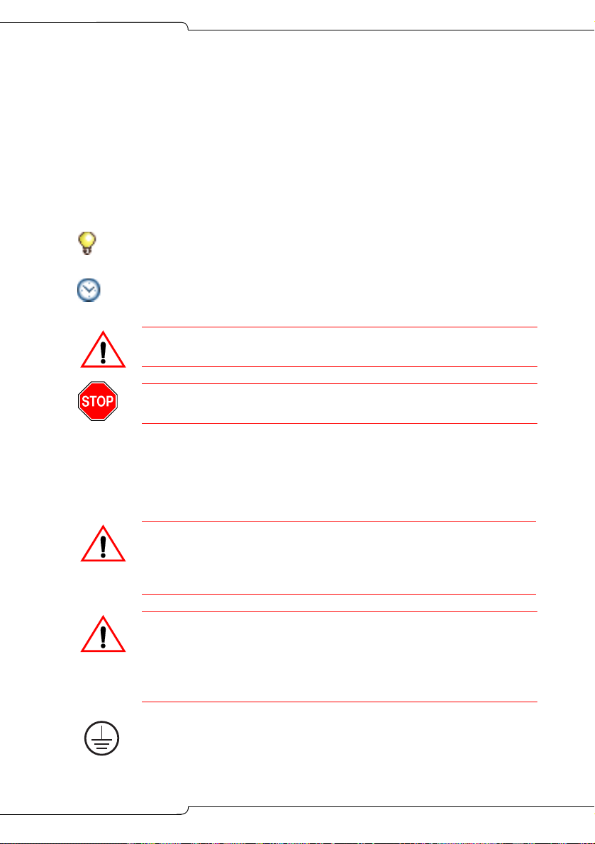
Tip: Provides additional information you should know about a topic.
Time: Indicates the time it takes to complete a procedure.
CAUTION: Indicates a potentially hazardous situation that
could result in damage to the equipment.
WARNING: INDICATES A HAZARDOUS SITUATION THAT
COULD RESULT IN INJURY OR DEATH.
Safety Instructions
A printable version of the Safety Instructions is available on the Mitel
Customer Documentation web site.
CAUTION: Failure to follow all instructions may result in
improper equipment operation and/or risk of electrical
shock. Refer to “3300 Safety Instructions” for complete
safety information.
CAUTION: To prevent ESD damage to the equipment: (1)
Ensure that the system is grounded bef ore you install a card.
(2) Whenever you handle cards, wear an anti-static strap
(attached to the cabinet). (3) When removing cards from the
cabinet, immediately place them in an anti-static bag.
Note: The ground symbol within a circle identifies the terminal to be
connected to an external protective conductor. Connect this terminal to
earth ground before you make any other connections to the equipment.
3
Page 14

3300 ICP Technician’s Handbook
Start Here Guide
What You Received
Options sheet with password from Mitel OnLine (see page 11)
3300 ICP Controller
Hard drive
System ID module or System i-Button
Software CD-ROM
NSU, ASU (optional)
Set of feet, rack ears, and screws for each unit
Review your purchase order for other, optional, components.
Installation Tools and Equipment
Installation Planner (Appendix B on page 295)
Typical Network Configurations (Appendix C on page 317)
Computer for programming the 3300 ICP
CAT 5 or better Cable with RJ-45 connector
IP addresses for the controller, E2T, and IP telephones
List of purchased options and password
IMAT (not required if you have Embedded PRI)
Phillips screwdrivers
Static strap.
4
Page 15

Introduction
Installation Checklist
Obtain your options and password from Mitel OnLine
Complete the Installation Planner Appendix (see page 295)
Install controller hardware (see page 15)
Connect maintenance PC to Controller (see page 22)
Power up the Controller (see page 22)
Launch the System Administration Tool (see page 8)
Program the License and Options Selection (see page 25)
Perform a DBMS Save (see page 25)
Set the Date and Time (see page 26)
Program the Controller modules (see page 26)
Establish an Ethernet connection to the Controller (see page 27)
Set the Controller RTC IP address (see page 28)
Program the DHCP server (see page 29)
Configure the Layer 2 switch (see page 35)
Install NSU, ASU, Peripheral Cabinet, DSU, SUPERSET™ Hub
(page 36)
Program Units and Modules (follows each installation procedure)
Install Telephones (see page 51)
Register IP Devices (see page 52)
Program Telephones (see page 54)
Install a DNIC Music on Hold /Paging Unit (see page 57)
Program Trunks (see System Administration Tool OnLine Help)
Program Automatic Route Selection (see OnLine Help)
Program Voice Mail (see OnLine Help)
Program Paging (see OnLine Help)
Program Music on Hold (see OnLine Help)
Program Automatic Call Distribution (see OnLine Help)
Program Hotel/Motel (see OnLine Help)
Perform a DBMS Save (see page 25)
5
Page 16

3300 ICP Technician’s Handbook
About the 3300 ICP
The 3300 ICP is a Voice over IP solution that delivers voice capabilities
and features to the enterprise. There are several system configurations:
the 100-user system; the MX with embedded analog, that can support 200
users; the CX and the CXi with embedded analog and embedded Layer2
switch for sites with an 8-64 line size; the MXe base with embedded analog
that can support 200 users before expansion; and the LX that can sup port
700 users (with 256 MB RTC memory) or 1400 users (with 512 MB RTC
memory from Release 6.0).
Programming Tools
The system includes a number of programming tools:
• Embedded System Management (ESM) consists of:
- System Administration Tool that provides a Web-based interface
that trained technicians use to program the system.
- Group Administration Tool that provides a Web-based interface
to enable administrators to make changes to user information.
- Desktop Tool that provides a Web-based interface to enable
display IP telephone users to program feature keys on their phone.
• Configuration Wizard, introduced with Release 7.0, allows you to
customize initial system programming. After you specify the system
setup, you can save the details for future use or apply the changes to
the 3300 ICP.
• ISDN Maintenance and Administration Tool (IMAT) provides the
programming interface for PRI and R2 protocols delivered via a n NSU
or DSU. Embedded PRI via the Dual T1/E1 Framer is programmed
though the System Administration Tool.
• ICP Software Installer Tool expedites the distribution of 3300 ICP
software by eliminating a number of interactive steps (see page 69).
The tool restores saved databases and, from Release 7.0 UR1,
enables databases from legacy SX-2000
MicroLIGHT, 3200 ICP, and 3800 WA G systems to migrate to the
3300 ICP. The Software Installer Tool replaces the Configuration Tool.
• Configuration Tool restores saved databases and enables legacy
SX-2000
systems to migrate to the 3300 ICP.
®
LIGHT, SX-2000 MicroLIGHT, 3200 ICP, and 3800 WAG
®
LIGHT, SX-2000
6
Page 17

Introduction
• IP Phone Analyzer collects performance information about the IP
devices connected to the 3300 ICP. You can use one PC to monitor
the debug and status information of IP phones (see page 248).
•OPS Manager enables you to control the maintenance and operation
of a network of elements. With OPS Manager, you can, for example,
manage a network telephone directory, schedule move, ad d, change,
and delete user operations, and integrate the network telephone
directory with a directory service database.
Application Management Center (AMC)
The online licensing process, managed by the Mitel Application
Management Centre (AMC) allows Solution Providers who have accounts
on the AMC to manage software licenses online. Each company is able to
supply customers instantly if new licenses are required. Refer to
“Requirements for AMC Connection” on page 23 for Software Installer
Tool and 3300 ICP system networking requirements.
Installation/Maintenance Computer
You need a Windows-based computer to program, maintain and
troubleshoot the 3300 ICP, and to install/upgrade 3300 ICP software.
Computer Recommendations
• Windows
®
NT 4.0, Windows 2000, or Windows XP
Computer Requirements
• Windows 98, Windows NT 4.0, Windows 2000, or Windows XP
• Network interface card (NIC)
• 525 MB free disk space (minimum)
• Internet Explorer 6.0 with the latest Service Pack and 128-bit
encryption
• VT100™ emulator program
• FTP server (can be installed with Microsoft
Tip: Windows 98 with PWS does NOT include an FTP server application,
and will not work for the software installation/upgrade process unless a
third-party server application is used.
®
IIS or PWS, for example)
7
Page 18

3300 ICP Technician’s Handbook
Launching the Programming Tools
Embedded System Management Tools
To log into one of the ESM tools:
1. Launch a browser and go to the URL of the 3300 Controller https://<hostname>/main.htm (<hostname> is the name or IP address
assigned to the Controller if no DNS is available). Refer to “Setting the
Controller RTC IP address (for Release 6.0 and later)” on page 27 or
“Setting the Controller RTC IP address (prior to Release 6.0)” on
page 28.
2. The first time you connect, you must install the Mitel Root CA security
certificate (see “Secure Sockets Layer (SSL) and Security Certificate”
on page 236).
3. Log into the 3300 ICP ESM using the default username (system) and
password (password).
Tip: To prevent unauthorized use, change the username and password the
first time you log in.
4. Click the desired Tool (Desktop, Group Administration, or System
Administration).
5. You will be prompted to install some XML Components when you log
into the System Administration Tool for the first time. At the following
prompt, "Do you wish to install or upgrade the required XML
components?", click "Install Now". The install takes less than 30
seconds and you do not need to restart your computer.
Tip: Your PC must have the same subnet address as the RTC IP (for
example, 192.168.1.x) to launch ESM.
The system will allow up to 5 System Administration Tool users, 5 Group
Administration Tool users, and 10 Desktop Tool users at one time.
The System Administration Tool will temporarily lock you out for 15 minutes
after three consecutive attempts to log in have failed.
ISDN Maintenance and Administration Tool
To launch IMAT on the Installation/Maintenance PC:
• On the Start menu, point to Programs, and click IMAT.
8
Page 19

Introduction
Software Installer Tool
To launch the Software Installer Tool:
• On the Start menu, point to Programs, and click Mitel 3300 ICP
Software Installer Tool.
IP Phone Analyzer
To launch the IP Phone Analyzer:
• On the Start menu, point to Programs, and click Mitel IP Phone
Analyzer (see page 248 for details).
3300 ICP Documentation
The 3300 ICP documentation set includes the following components:
• Printed documents (also available on Mitel OnLine)
- General Information Guide
- Technician’s Handbook
- Safety Instructions
• Documents on Mitel OnLine
- Hardware Technical Reference Manual
- System Administration Tool Help
- Voice Clustering (Portable Directory Number)
- Resiliency
- IP Phone Analyzer Online Help
- Software Installer Tool Help
- IP-DECT Wireless Solution Documentation
- CITELlink Gateway Documentation
- Symbol NetVision MiNET Phone Installation and Pro gr amm in g
Instructions
- SpectraLink Documentation
- Engineering Guidelines
- Telephone, Attendant, and Voice Mail User Guides
- 6000 Managed Application Server (MAS) Documentation
9
Page 20

3300 ICP Technician’s Handbook
• Online Help
- System Administration Tool Online Help
- Group Administration Tool Embedded Help
- Desktop Tool Embedded Help
- IMAT Online Help
- IP Phone Analyzer Online Help
- Software Installer Tool Online Help
- OPS Manager Online Help
Tip: In the software application (System Adm inistration Tool, IMAT,
etc.), click the Help link or button to access the tool’s Online Help.
• Knowledge Base Articles on Mitel OnLine
- Technical Bulletin
- How-To Guide
- Troubleshooting Guide
- Known Product Issue
- Release Notes
- Program Information.
Mitel OnLine
You can access Mitel OnLine from the www.mitel.com Web site.
Tip: You must be a registered user to access Mitel OnLine.
Access Product and Technical Documentation
1. Log into Mitel OnLine.
2. Click Technical Support.
3. Click Product Documentation for Technical Documents, User
Guides, and Installation Guides.
-ORClick Knowledge Base for TBs and RNs.
Tip: To view a document, click on the name of the document.
To download a document, right-click on the name of the document
and select Save Target As.
10
Page 21

Introduction
Create Telephone User Guides with ManualMaker
1. Log into Mitel OnLine.
2. Click Technical Support and then click Product Documentation.
3. Click ManualMaker.
4. Click the Help button for instructions on creating User Guides with
ManualMaker.
Access Your Mitel Options Password
You must obtain your Mitel Options Password through Mitel OnLine
(www.mitel.com). This password is required during a software upgrad e or
installation procedure, so you MUST keep a proper record of it. A new
password is issued to you if you are purchasing new options. Before
attempting to upgrade software, to confirm a current password or to
purchase new options and receive a new password, call Mitel Customer
Service during normal business hours.
Contacting Mitel
Sending Feedback
If you have suggestions on how to improve this documentation, please
contact us at techpubs@mitel.com.
Order Desk
You can reach the Order Desk at 1-800-796-4835.
Repair Department
You must get a Return of Merchandise Authorization (R MA) form from the
Repairs Department before sending equipment back to Mitel.
You can reach the Repairs Department at 1-888-222-6483.
Technical Support
Please contact Mitel Technical Support if you require technical assistance.
If you cannot resolve the problem by using the Troubleshooting chapter
(page 165), please collect the required information listed in the applicable
section(s) of the Troubleshooting chapter before calling Mitel Technical
Support.
You can reach Technical Support at 1-800-561-0860 or 1-613-592-2122.
11
Page 22

3300 ICP Technician’s Handbook
12
Page 23

Chapter 2
Installation
Page 24

3300 ICP Technician’s Handbook
14
Page 25
Installation
Install Controller Components
This chapter contains instructions on how to install a 3300 ICP. F or
information on upgrading and replacing components, see page 104.
In the following illustrations, the components listed in bold text are
installed in the factory (Release 7.0 and later). If you receive a
CX/CXi/MXe and those identified components are not installed, refer to
Chapter 4 on page 95 for installation instructions.
Tip: In the following illustrations, T1/E1 refers to Dual T1/E1 or T1/E1 Combo,
with exception of the CX/CXi controllers which support only the Combo.
Slot 8
DSP
SysID
Slot 1
Power Supply
FIM, T1/E1, or
BRI
Slot 7
DSP
Slot 2
FIM, T1/E1, or
BRI
Slot 6
Echo Canceller or
DSP
Slot 3
FIM, DSP, T1/E1,
or BRI
Slot 5
Echo Canceller
Slot 4
FIM, DSP
Figure 1: Slot Locations for the LX, 250, and 700-User Controllers
Power
Supply
Slot 1
FIM, T1/E1, or
BRI
FIM, DSP, T1/E1,
Analog Main Board
Analog Option Board
(optional, installed on AMB)
Clock Module SysID
Slot 2
BRI
Slot 3
DSP, T1/E1, or
BRI
Hard Drive
Slot 4
DSP
Figure 2: Slot Locations for the MX Controller
15
Page 26

3300 ICP Technician’s Handbook
Hard Drive
or RAID
Clock Module
Slot 6
DSP or Echo Canceller
Slot 1
FIM, T1/E1,
BRI
Analog Main Board PSU 2 PSU 1
Slot 2
FIM, T1/E1,
BRI
Figure 3: Slot Locations for the MXe Controller
Hard Drive
Slot 1
Combo (T1/E1,
DSP, Echo), BRI
Figure 4: Slot Locations for the CXi Controller
Slot 5
DSP or Echo Canceller
Slot 3
FIM, DSP,
T1/E1, BRI
Power
Supply
Clock Module i-Button
Slot 2
Combo (T1/E1,
DSP, Echo), BRI
Slot 4
FIM, DSP,
T1/E1, BRI
Analog Main Board
Analog Option Board
Slot 3
DSP
(with an Ethernet L2 Switch)
i-Button
(optional)
16 Port Ethernet
L2 Switch
Hard Drive
Slot 1
Combo (T1/E1,
DSP, Echo), BRI
16
Power
Supply
Clock Module i-Button
Slot 2
Combo (T1/E1,
DSP, Echo), BRI
Analog Main Board
Analog Option Board
(both optional)
Slot 3
DSP
Figure 5: Slot Locations for the CX Controller
(without an Ethernet L2 Switch)
Page 27
SysID
Installation
Slot 1
FIM, T1/E1, or
BRI
Power Supply
Slot 2
FIM, T1/E1, or
BRI
Slot 3
DSP or BRI
Slot 4
DSP
Figure 6: Slot Locations for 100-User Controller
Read the Safety Instructions before performing the procedures in this
chapter (see “Safety Instructions” on page 3).
CAUTION: To prevent ESD damage to the equipment: (1)
Ensure that the system is grounded before you install a
card. (2) Whenever you handle cards, wear an anti-static
strap (always attach the wrist strap from the cabinet).
Tip: Before installing a 3300 ICP, always read the RN for the software you
are installing (see “3300 ICP Documentation” on page 9).
CAUTION: All installation, field replacement, and servicing
procedures must be carried out by service personnel who
have successfully completed the Mitel Installation and maintenance training course.
CAUTION: Provide a permanent ground for all controllers
and units, through the ground connection o n e ach cabine t.
Connect the installation/maintenance PC to the Controller (page 22)
Power up the Controller (see page 22)
Launch the System Administration Tool (see page 8)
Complete basic programming and Data Save (see page 25)
Establish an Ethernet connection to the Controller (see page 27)
Set the Controller RTC IP address (see page 28)
Program the DHCP server (see page 29)
Configure the Layer 2 switch (see page 35)
Install the Units (see page 36)
Install the Telephones and peripherals (see page 51)
17
Page 28
3300 ICP Technician’s Handbook
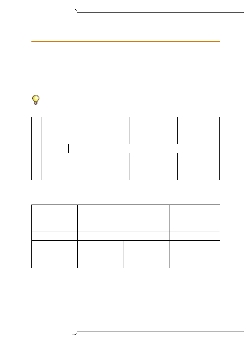
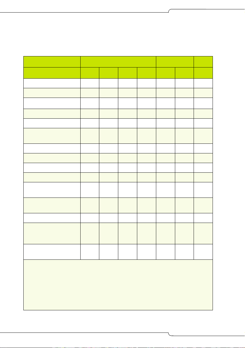
Controller Component Options
Table 1: Controller Component and Upgrade Options
Processor speed
Components 100 250 700 MX LX
CIM √√√√√√—
FIM (page 104) √ √ √ √ √ √ —
DSP (page 105) √
T1/E1 (page 110) √ √ √ √ √ √ —
BRI (page 110) √√√√√√√
T1/E1 Combo
√ √ √ √ √ √ √
(page 111)
AMB (page136) ————— √√
AOB (page 114) — — — — — — √
AMB (page 134) — — — √ ———
AOB (page 113) — — — √ — — —
Redundant Power
————— √ —
Supply (page 123)
RAID controller
— — — — — √ —
(page 116)
E2T (page123) —————√ —
Upgrading to a 300 or
— √ √ — — — —
450 MHz Controller
(page 102)
Upgrading to a
————
1400-User System
Note: 1. Requires 3300 ICP software version 3.2 or higher.
2. 64 compression channels requires a minimum 300 MHz controller.
3. Requires a controller with 512 MB of memory on the RTC
(Rls 6.0 or later).
4. The CX only supports Release 6.0 o r lat e r software.
5. Release 7.0 and later software.
6. Requires the installation of a second processor, the E2T.
7. Refer to page 365 for component part numbers.
1
300
2
√
2
√
√√√√
450 266
MXe5CX
3
√
6
√
4
—
18
Page 29

Installation
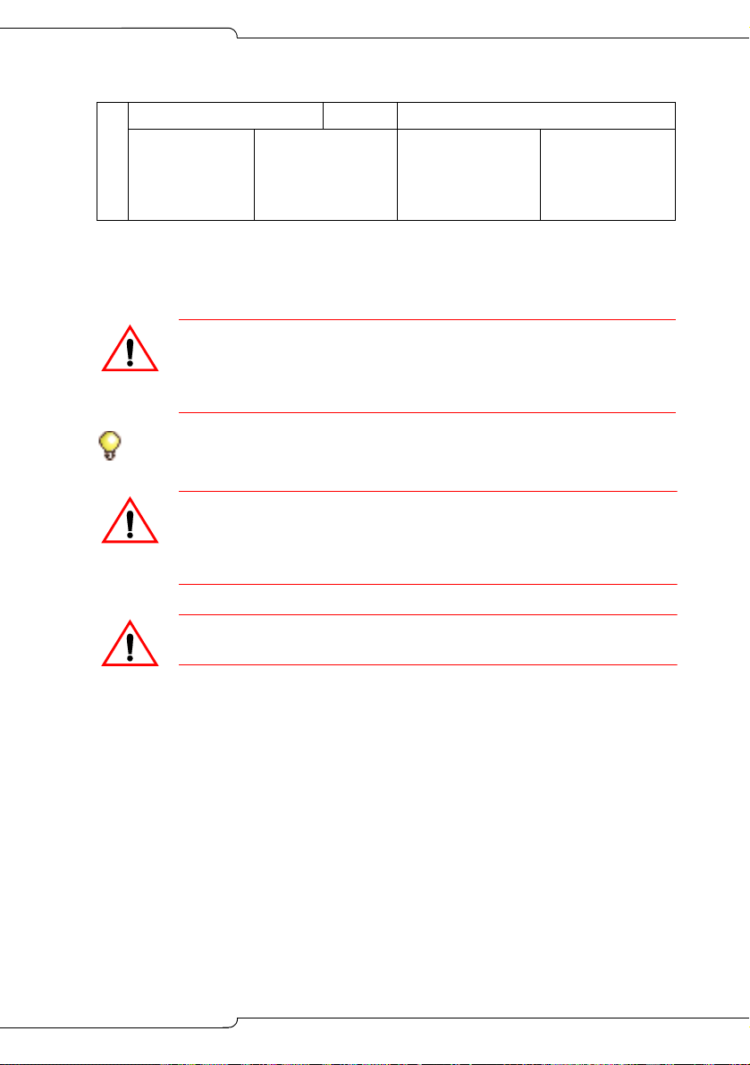
Hard Drive
CAUTION: If you move a programmed hard drive from one
controller type to another (for example, an MX system to an LX
or CX system), you MUST manually install the software (see
page 77) and restore the database. A new hard drive purchased from Mitel is configured for installation in any system.
Tip: The CX/CXi/MXe controllers are shipped with the hard drive installed.
If you receive a CX/CXi/MXe and the hard drive is not installed, refer to
page 128 or page 131 for installation instructions.
LX, 100, 250 and 700-User Hard Drive
To install a new hard drive in a new LX/100/250/700-user controller:
1. Remove the controller from its packaging.
2. Remove the hard drive and attached backing plate from its packaging.
3. Locate the hard drive ribbon cable and power cable in the controller
hard drive enclosure.
4. Cut an d disc ar d th e tie wr ap securin g the ca ble s to th e contr olle r
stand-off post.
5. Connect the power and ribbon cables in the hard drive enclosure to the
corresponding connectors on the har d dr ive .
6. Inse rt th e ha rd driv e.
7. Secure the plate to the controller using the 6 border screws provided
with the hard drive.
MX Hard Drive
To install a new hard drive in a new MX controller:
1. Remove the controller and hard drive from their packaging.
2. Remove the top cover of the controller (see page 100).
3. Discard the backing plate that is shipped with the hard drive.
4. Locate the hard drive ribbon cable and power cable in the controller
hard drive enclosure.
19
Page 30

3300 ICP Technician’s Handbook
5. Connect the power and ribbon cables to the corresponding connectors
on the hard drive.
6. Insert the hard drive.
7. Secure the hard drive to the controller using the screws provided.
System ID Module
Tip: The CX/CXi/MXe controllers are shipped with the i-Button installed. If
you receive a CX/CXi/MXe and the i-Button is not installed, refer to page 133
for installation instructions.
To install a SysID module in a LX/MX/100/250/700-user controller:
1. Remove the System ID module from its packaging.
2. Remove the protective cover from the System ID module’s connector.
3. Remove the controller cover (see page 99 or page 100).
4. Install the module connector in its mate on the controller.
- 100-user controller: behind slot 2
- MX controller: behind slot 4
- LX and 250/700-User controller: between slots 1 and 8.
5. Secure the System ID module using the screw provided.
Other Controller Components
Refer to “Upgrades and FRUs” on page 95 for instructions to install
additional controller components.
Mounting the MXe Controller
Tip: Mount the MXe in a rack without the hard drives and power supplies to
reduce the weight.
To rack-mount the MXe:
1. Attach the mounting brackets to the MXe using the flat head screws
provided.
2. Loosel y in st all on e fr am e mou nt ing sc re w on eac h side of th e fra m e:
- in the bottom hole position of the space that the MXe will occupy.
20
Page 31

Installation
- loosely enough that the frame mounting bracket can be dropped
into position, resting on the screw thread (see Figure 7).
3. Position the MXe on the frame, resting the MXe mounting brackets on
the frame mounting screw thread.
- The MXe will rest on those screws while the remaining screws are
installed.
4. Install two more screws on each side of the frame, in the 3rd and 6th
hole positions.
5. Tighten all six of the mounting screws.
CAUTION: Remove the MXe from the rack in reverse order.
Loosen the bottom screws before the other screws are
removed.
Never turn the bottom screws while the rack is resting on
them.
Figure 7: MXe Rack-mount Screw Placement
21
Page 32

3300 ICP Technician’s Handbook
Connecting the Maintenance PC to the Controller
1. Connect an RS-232 straight DTE male to female serial cable between
the controller’s Maintenance port and the PC’s serial port (cable not
provided).
2. Program the PC’s serial port (from the communication program) with
the following settings:
- Baud Rate: 9600
- Data Bits: 8
- Parity: None
- Stop Bits: 1
- Flow Control: None
3. Connect a straight-through Ethernet cable (RJ-45) from the controller
leftmost Ethernet port (port 17 on the CXi; port 1 o n the MX e) and th e
PC’s network interface card (NIC).
4. Program the PC’s NIC with the following settings:
- IP Address: 192.168.1.n (where n is a value between 30 and 254)
- Subnet Mask: 255.255.255.0
Powering Up the Controller
1. Connect the female end of the power cable to the controller, and
secure it with the latch (if provided).
2. Connect the other end of the power cable to a protected outlet. If
necessary turn on power switch. The controller turns on.
Time: The controller can take up to 10-15 minutes to start-up.
Verify the Connections
Perform the steps below to verify the connections between the
Maintenance PC and the controller.
1. To verify the serial connection, in the VT100 emulator, press ENTER.
- If the serial connection is installed and programmed properly, a
right-pointing arrow (→) is displayed when you press ENTER.
2. To verify the Ethernet connection, from the PC, PING the controller’s
RTC IP address (default is 192.168.1.2).
- If the connection is installed and programmed correctly, the
controller replies to the PING.
22
Page 33

Installation
Requirements for AMC Connection
Connecting to the Application Management Center (AMC) Server requires
specific settings for the Software Installer Tool and the 3300 System
Administration Tool.
Software Installer (SI) Tool Requirements
The PC that is running the SI Tool has the following network requirements:
1. DNS Name Resolution: Because the SI win32sync client performs a
name lookup on “register.mitel-amc.com”, the SI host PC needs to be
properly configured for DNS name resolution.
2. TCP/IP Source Port on the SI Host: A Windows operating system will
use an arbitrary high port for the TCP connection to th e AMC. If the SI
PC is behind a firewall, the firewall must allow connections from high
ports (greater than 1024).
3. TCP/IP Destination Port on the AMC: The SI win32sync client will
attempt to establish a connection to register.mitel-amc.com TCP port
22. After 5 seconds, if the connection is not established, the client will
try port 8222. If there is still no success, the third attempt is with port
80 using the HTTP/1.1 protocol CONNECT me th od .
If the SI PC is behind a firewall, the firewall must allow connection to
at least one of port 22, port 8222, or port 8.
4. SI Host PC behind an HTTP Proxy Server: If the HTTP/1.1
CONNECT method is used and the SI PC is configured to use an
HTTP proxy server, then the CONNECT request will be through the
proxy server. This is the same method used by web browsers to
establish HTTPS connections through proxy servers. If the SI host PC
can reach https://www.mitel-amc.com from a web browser, then it
should also be able to establish a win32sync connection by using the
HTTP/1.1 CONNECT method. If there is a problem reaching
https://www.mitel-amc.com from a browser on the SI host PC, then the
firewall and/or proxy server on the customer pr emise ma y nee d to be
reconfigured to allow HTTP/1.1 CONNECT requests.
3300 ICP System Requirements
1. DNS Name Resolution: Because the MiSync client performs a name
lookup on “register.mitel-amc.com” and “sync.mit el-amc.com”, the ICP
needs to be properly configured for DNS name resolution using the
System IP Configuration form in the System Administration Tool.
23
Page 34

3300 ICP Technician’s Handbook
2. TCP/IP Source Port on the ICP: The MiSync client will connect to
TCP port 443 (https) on the AMC. If the ICP is behind a firewall, the
firewall must allow TCP connections from the ICP to TCP port 443 on
the AMC.
3. ICP behind an HTTP Proxy Server: The MiSync client uses HTTPS
to communicate with the AMC. The HTTP/1.1 CONNECT method is
the standard used by proxy servers to proxy HTTPS. There should be
no extra configuration work required. See Step 4, “SI Host PC behind
an HTTP Proxy Server“ on page 23.
4. CX/CXi/MXe-Specific WAN Considerations: Program the Internet
Gateway (WAN interface) IP address details (see "CXi/MXe
Requirements for IP Networking" on page 297).
24
Page 35

Installation
Basic Programming and Data Save
Programming the License and Option Selection Form
Tip: Installations and upgrades require a new purchased-options password
from the Mitel Application Management Center (AMC). If you use the old
password, an error message is displayed.
Tip: Before you make any changes to Configuration Options, after entering
the Mitel Options Password and programming the database, ensure that you
have a system backup.
To select licenses and options prior to software release 6.0:
1. Log into the System Administration Tool (see page 8).
2. Select the License and Option Selection form.
3. Click Change and fill in the fields as required (see your Mitel Options
sheet). For more information, click Help.
Tip: When you Change and Save in the License and Option Selection form
(prior to Release 7.0), an error message that references “sysid # 65535“
means that the SysID or i-Button is not installed or not seated correctly.
Tip: Enable Networking Option and Mitai/Tapi Computer Integration.
4. Enter the Mitel Options Password and click Save.
Time: The Save procedure takes approximately three minutes.
5. Reboot the controller (see page 99).
To manually select licenses and options for release 6.0 and later:
1. Access the License and Option Selection form.
2. Click Change and leave the Application Record ID field blank.
3. Enter the number of licenses in the appropriate fields.
4. Select the appropriate Country variant and Configuration Options.
5. Enter your Password.
6. Click Save to commit your changes to the database.
7. Reboot the controller (see page 99).
25
Page 36

3300 ICP Technician’s Handbook
T o automatically select licenses and options for release 6.0 and later:
1. Complete the System IP Configuration form to enable the Primary
and Secondary DNS Servers to establish a connection with the
Application Management Center (AMC) Server (see "Requirements
for AMC Connection" on page 23).
Tip: The PC that is running the Software Installer Tool has networking
requirements that must be met to establish a connection with the AMC. Refer
to "Installing the Software Installer Tool" on page 69 for details.
2. Access the License and Option Selection form.
3. Click Change and enter your Application Record ID.
4. Click Retrieve Licenses to query the Applicatio n Management Center
(AMC) and retrieve your Purchased Options and Password.
5. Select the appropriate Country variant and Configuration Options.
6. Click Save to commit your changes to the database and to the AMC.
7. Reboot the controller (see page 99).
Setting the Date and Time and Saving the Settings
Tip: The DBMS SAVE command will ensure that all future programming
changes are saved. You must perform the DBMS SAVE command before
the programmed internal DHCP server will run (see page 29 for DHCP
programming instructions).
To set the system date and time:
1. Log into the System Administration Tool (see page 8).
2. In the All forms (alphabetical) list, click Maintenance Commands.
3. Enter writedatetime <year> <month> <day> <day of the week>
<hours> <mins> <seconds> to set the date and time. For example,
writedatetime 2004 4 3 2 12 31 51 (2004 April 3rd Tuesday 12:3 1:51).
4. Perform a DBMS save using the dbms save maintenance command.
5. Enter the dbms stat command to verify the DBMS save.The system
response is DBMS info: DBMS_INITIALIZED is on.
Programming the Controller Modules
1. Access the Controller Module Configuration form.
2. Highlight the module (slots 1 to 4) and click Change.
26
Page 37

Installation
3. Select the module in the drop-down list. Choose Dual FIM, Dual
Framer, Quad BRI Framer, or T1/E1 Combo.
4. If you have installed Framer or Combo modules, refer to “Program
Embedded PRI/Q.SIG Trunks”, “Program T1/D4 Trunks”, or “Program
Embedded BRI Trunks” in the Online Help for information.
5. Power down the controller (see page 99).
Connecting the Controller to the Network
This section assumes that the network is already set up, and that there is
a serial connection between the Maintenance PC and the controller.
Tip: See Table 58, “T1 and E1 Connector Pin Allocation,” on page 270 for
Embedded T1/E1 pinout information.
• Setting the Controller RTC IP address (prior to Release 6.0) (page 28).
• Programming DHCP (page 29)
• Verifying the Operation of the Controller (page 34).
• Configuring the Layer 2 Switch (page 35).
Setting the Controller RTC IP address (for Release 6.0 and later)
Tip: The Maintenance PC must be on the same subnet as the controller.
1. Launch a browser and go to the URL of the 3300 Controller (default
RTC IP address is 192.168.1.2, default gateway 192.168.1.1).
2. The first time you connect, you must install the Mitel Root CA security
certificate (see “Secure Sockets Layer (SSL) and Security Certificate”
on page 236).
3. Log into the 3300 ICP ESM using the default username (system) and
password (password).
4. Complete the IP Networking Configuration form to change the IP
addresses.
27
Page 38

3300 ICP Technician’s Handbook
Setting the Controller RTC IP address (prior to Release 6.0)
Tip: The Maintenance PC must be on the same subnet as the controller.
1. Start the communication program on the Maintenance PC.
2. Power up the controller (see page 22).
3. Press the Reset button on the controller (use a small non-metallic
pointed object).
4. The communication program will instruct you to Press
<SPACE><SPACE><SPACE> to stop auto-boot AFTER
countdown starts (Release 5.2 and later) or Pres s any k ey to s top
auto-boot (prior to Release 5.2).
5. When [VxWorks Boot]: is displayed, type c and press ENTER.
6. For each VxWorks setting shown in bold inTable 76 on page 300,
enter a value, and then press ENTER. For all other settings, press
ENTER to accept the default:
Tip: If DHCP (flags=0x40) is being used on the E2T, leave the inet on ethernet
field blank.
- inet on ethernet (e),
RTC (Get it from your IT administrator.)
IP address and subnet mask (hex) for controller
- gateway inet (g), IP address of the default gateway for the 3300 (must
be outside the DHCP range)
- user (u), ftp
- ftp password (ftp)), ftp.
CAUTION: Do not use leading zeroes in the IP addresses.
For example, enter 192.168.1.2; not 192.168.001.002.
7. At [VXWorks Boot], type @, or press the Reset button on the
controller.
Time: The controller can take up to 10–15 minutes to restart.
28
Page 39

Installation
Programming DHCP
Programming the Controller DHCP Server Settings (prior to Rls 7.0)
For additional information on programming DHCP settings for the 3300
ICP, refer to the System Administration Tool Online Help.
To use an external DHCP Server, do not enable the internal DHCP server
and refer to “Configuring External DHCP Settings for E2T” on page 307 for
instructions.
Tip: You may need to change the IP address of your PC to match your
customers network.
1. On the Maintenance PC, access the System Administration Tool (see
"Launching the Programming Tools" on page 8).
2. In the All forms (alphabetical) list, click DHCP Subnet form, enter
the subnet name, IP address and bit mask.
3. In the DHCP Static IP form, enter a static IP address for the E2T using
the information on page 301 (skip this step for the MX and 100-user
controllers). Assign IP addresses to specific devices by using the MAC
address of the device. Assign a static IP Address to any IP Console in
a cluster.
4. In the DHCP IP Address Range form, program the scope using the
information on page 301.
Tip: The following IP addresses are reserved for the AMB and ASUs:
192.168.10.1 to 192.168.10.15 through 192.168.13.1 to 192.168.13.15
5. In the DHCP Options form, program the options listed in Table 78 on
page 301 for the scope you just programmed. Always create the
following options:
- 3 Router, IP address
- 66 TFTP Server, IP address format
- 67 Boot file, string value (always /sysro/E2T8260)
- 128 TFTP, IP address format (typically the controller)
- 129 RTC, IP address format (typically the controller)
- 130 MITEL IP PHONE, string value
In a single DHCP configuration, create the following options:
- 132 VLAN ID (optional)
29
Page 40

3300 ICP Technician’s Handbook
- 133 Priority, integer value of 1-6 (Optional. Required if a voice
VLAN is in use. For external server use Hex LONG; for internal
server use decimal value of 1-6)
- 134 Diffserv Code Point, integer value
If there are 5230 IP Appliances, create the following options:
- 6 DNS Server, IP address format
- 44 NetBIOS Name Server, IP address format
6. In the DHCP Options form, for a cluster environment, program IP
Console (if any) with a static IP Address. Then, do the following:
Program Options 128 and 129 with:
- Format: IP Address
- Value: IP Address of the controller that controls the device
- Scope: Static: <device name><subnet>.
If different VLAN tagging and priority information is needed for the IP
Console, repeat step 6 for Options 132 and 133.
If a different router is need for any IP Consoles, repeat step 6 for
Option 3 and set the Value to the IP address of the router.
7. In the DHCP Lease Viewer form, ensure that there is no DHCP IP
Address Lease for the IP Console MAC Addresses. If there is, delete
it and then power off and power on the device.
8. In the DHCP Server form, enable the internal DHCP server.
To use an alternative DHCP server (see page 307 and page 308):
1. In the DHCP Server form, disable the internal DHCP server.
2. Program your DHCP server with the following options:
- 128 TFTP IP address format
- 129 RTC IP address format
- 130 MITEL IP PHONE, string value.
30
Page 41

Installation
Programming the Controller DHCP Server Settings (for Release 7.0 and
later)
Note: DHCP options 128-133 used to configure Mitel IP endpoints have
been reclassified as public options by the Internet Engineering Task Force
(see RFC 2133 and RFC 3925). To comply with the change, Mitel
recommends using either option 43 or 125, depending on the server's
ability to support them and on administrator preference. (The embedded
server supports both options with 125 as the factory-programmed default.)
The old options can still be used to provide backward compatibility with
IP sets that have yet to be upgraded with firmware that supports the new
options. After the upgrade, the old options may be removed to prevent
future conflicts with standard use or other vendors' use of these options.
Note: Ensure that all LLDP-compliant telephones are upgraded to
firmware version 2.0.0.18 or later before you use LLDP on your network
for VLAN Discovery.
Note: LLDP-MED non-compliant telephones cannot use LLDP for VLAN
discovery. They must use DHCP VLAN discovery. Non-compliant sets are:
5001, 5005, 5010, 5020 IP Phones, 5140 IP Appliance, 5201, 5205, 5207,
5215 (single mode), 5220 (single mode), 5230 IP Phones, 5240 IP
Appliance, 5485 IP Pager, and 5550 IP Console keypad.
For additional information on programming DHCP settings for the 3300
ICP, refer to the System Administration Tool Online Help.
To use an external DHCP Server, do not enable the internal DHCP server
and refer to “Configuring External DHCP Settings for E2T” on page 307 for
instructions.
Tip: You may need to change the IP address of your PC to match your
customers network.
1. On the Maintenance PC, access the System Administration Tool (see
"Launching the Programming Tools" on page 8).
2. In the All forms (alphabetical) list, click DHCP Subnet form, enter
the subnet name, IP address and bit mask.
3. In the DHCP Static IP form, enter a static IP address for the E2T using
the information on page 301 (skip this step for the MX and 100-user
controllers). Assign IP addresses to specific devices by using the MAC
address of the device. Assign a static IP Address to any IP Console in
a cluster.
4. In the DHCP IP Address Range form, program the scope using the
information on page 301.
31
Page 42

3300 ICP Technician’s Handbook
Tip: The following IP addresses are reserved to provide backward
compatability for legacy AMBs and ASUs:
192.168.10.1 to 192.168.10.15 through 192.168.13.1 to 192.168.13.15
The ASU II and legacy AMBs and ASUs with upgraded firmware use the
following reserved addresses:
169.254.10.0 to 169.254.10.15 through 169.254.19.0 to 169.254.19.15
5. In the DHCP Options form, program the options listed in Table 78 on
page 301 for the scope you just programmed. Always create the
following options:
Note: IP sets require a firmware upgrade to support the new DHCP
options introduced in Release 7.0; otherwise, the sets will fail to boot. Such
failures can occur, for example, in a resilient cluster of mixed software
releases or when sets with old firmware are added to a controller after it
was upgraded to Release 7.0. For the sets to boot, DHCP options 128-133
must be present in the DHCP server. After the sets have booted, options
128-133 may be removed to avoid future conflicts with standard use or
other vendors’ use of these options.
- 3 Router, IP address
- 125 Vendor-Identifying Vendor-Specific Information or Option 43
Vendor Specific Information. Option 125 is the preferred option.
- 66 TFTP Server, IP address format
- 67 Boot file, string value (always /sysro/E2T8260)
If there are 5230 IP Appliances, create the following options:
- 6 DNS Server, IP address format
- 44 NetBIOS Name Server, IP address format
6. In the DHCP Options form, for a cluster environment, program IP
Console (if any) with a static IP Address. Then, do the following:
Program Option 125 (preferred) or Option 43 with:
- Format: ASCII String
- Value: IP Address of the controller that controls the device and
different VLAN tagging and priority information if needed for the
console
- Scope: St atic: <device name><subnet>.
Assign the address Option 125 (or 43) as above, specifying differ ent
VLAN tagging and priority information if needed for the console.
32
Page 43

Installation
If a different router is need for any IP Consoles, repeat step 6 for
Option 3 and set the Value to the IP address of the router.
7. In the DHCP Lease Viewer form, ensure that there is no DHCP IP
Address Lease for the IP Console MAC Addresses. If there is, delete
it and then power off and power on the device.
8. In the DHCP Server form, enable the internal DHCP server.
To use an alternative DHCP server (see page 307 and page 308):
1. In the DHCP Server form, disable the internal DHCP server.
2. Program your DHCP server with options 128-133.
3. Upgrade the IP Phones/ firmware to 2.0.0.18 or later.
4. Program your DHCP server with the following options:
- 43 Vendor Specific Information, string value
OR
- 125 Vendor-Identifying Vendor-Specific Information, string value.
5. Delete options 128-133.
Note: IP sets require a firmware upgrade to support the new DHCP
options introduced in Release 7.0; otherwise, the sets will fail to boot. Such
failures can occur, for example, in a resilient cluster of mixed software
releases or when sets with old firmware are added to a controller after it
was upgraded to Release 7.0. For the sets to boot, DHCP options 128-133
must be present in the DHCP server. After the sets have booted, options
128-133 may be removed to avoid future conflicts with standard use or
other vendors’ use of these options
Note: Ensure that all LLDP-compliant telephones are upgraded to
firmware version 2.0.0.18 or later before you use LLDP on your network
for VLAN Discovery.
Note: LLDP-MED non-compliant telephones cannot use LLDP for VLAN
discovery. They must use DHCP VLAN discovery. Non-compliant sets are:
5001, 5005, 5010, 5020 IP Phones, 5140 IP Appliance, 5201, 5205, 5207,
5215 (single mode), 5220 (single mode), 5230 IP Phones, 5240 IP
Appliance, 5485 IP Pager, and 5550 IP Console keypad.
Program DHCP for VLAN (prior to Release 7.0):
Follow this procedure if using two DHCP servers: central server (external)
on a default VLAN and other (3300 DHCP Server) on the voice VLAN.
33
Page 44

3300 ICP Technician’s Handbook
1. Set up the central DHCP Server with the following options:
- 130 MITEL IP PHONE, string value
- 132 VLAN ID
- 133 Priority, value of 1-6
- 134 Diffserv Code Point, integer value
2. Set up the 3300 ICP DHCP Server with the following options:
- 128 TFTP IP address format
- 129 RTC IP address format
- 130 MITEL IP PHONE, string value
- 132 VLAN ID
- 133 Priority, value of 1-6
- 134 Diffserv Code Point, integer value
3. Program the DHCP server on the 3300 ICP (see procedure above).
Verifying the Operation of the Controller
1. On the Maintenance PC, access the System Administration Tool.
2. In the System Hardware Profile folder, verify that the information in
each of the forms is correct, including the IP address of the E2T for the
LX and 250/700-user system.
3. In Maintenance and Diagnostics, click Alarm Details.
Verify that the following alarms do not appear ( if yo u get an alarm, g o
to “Alarms” on page 189):
- E2T Com (not applicable to the MX, CX/CXi, or 100-user controller)
- DSP
Tip: The next four steps are optional.
4. Connect two IP Phones directly to one of the controller’s Ethernet
ports (for an MX and 100-user controller, only the leftmost port is
functional and you must use a Layer 2 switch for these steps).
5. Program the IP Phones (refer to the System Administration Tool
Online Help for details).
6. Make a call from one phone to the other.
7. Remove the IP Phones from the controller.
34
Page 45

Installation
Configuring the Layer 2 Switch
The 3300 ICP requires a Layer 2 switch between its controller and the
network. The internal Layer 2 switch in the CXi and MXe must be
programmed with an IP Address in the same subnet as the RTC IP
Address, or the switch will not operate properly. Do this by completing the
System IP Configuration form, and then reboot the system.
Note: The 16 10/100 Mbps ports are disabled on the CXi during bootup;
likewise, the right-side Gigabit port on the MXe.
Tip: Refer to the System Administration Tool Online Help for detailed
instructions for programming the IP Network Configuration forms associated
with the CXi and MXe.
1. Connect an Ethernet cable between the Layer 2 switch on your
network and the leftmost available Ethernet port on the controller (port
17 on the CXi and the left Gigabit port on the MXe). Use a
straight-through cable for the CXi and MXe and a crossover cable for
all other controllers.
Tip: For an MX or 100-user system, move the Maintenance PC
Ethernet connection from the controller to one of the Layer 2 switch
input ports, and connect the Layer 2 switch to the lef tmost Ethernet
port of the controller. You can do the same for an LX, 250 and a
700-user system, if desired.
2. Program the Layer 2 switch with the appropriate settings (see
“Network Configuration Examples” on page 317 for more information).
Tip: Typically, in a VLAN environment, an access port is used to connect
the Layer 2 switch to the controller, and trunk ports to connect the Layer 2
switch to the IP Phones.
Tip: IP trunks cannot work through the WAN port.
- See your IT administrator for information to set up and program a
DHCP server. We recommend that you use the controller’s internal
DHCP server to provide a static IP address to the E2T.
3. If you are not using the controller’s DHCP server, disable it in the
DHCP Server form.
Tip: See “Configuring a Windows 2000 DHCP Server (prior to Release 7.0)”
on page 308 for information on programming 3300 ICP DHCP settings on a
Windows 2000 DHCP server.
35
Page 46

3300 ICP Technician’s Handbook
Install Units
This section contains detailed information on installing and configuring the
Network Services Unit, Analog Services Unit, Peripheral Cabinet,
SUPERSET HUB, and Digital Services Unit (DSU) for the 3300 ICP.
CAUTION: Provide a permanent ground for all controllers
and units, through the ground connection on each cabinet.
This section also contains information on configuring embedded analog on
the MX, MXe, and CX/CXi controllers.
Tip: The CX/CXi controllers do not support Network Services Units or Analog
Services Units. The CX/CXi do support embedded trunking and embedded
analog.
You can install any of the following Network Services Units (NSUs):
• Universal NSU (MSDN, PRI/QSIG, T1/D4)
• R2 NSU
• BRI NSU.
You can double the number of Universal and R2 NSUs in a system by
chaining a secondary NSU to each primary NSU connec te d to th e
controller. BRI NSUs cannot be chained.
Some NSUs must be programmed with the ISDN Maintenance and
Administration Tool (IMAT) (see “Install and Use IMAT” on page 88).
CAUTION: To connect your NSU to the LAN, you must
change the default IP and gateway addresses to match an
available address on the LAN. The default address is
192.168.1.1:ffffff00. See "Programming an IP Address into
the NSU" on page 88.
Universal or R2 Network Services Unit
1. Mount and secure the NSU in the desired location.
2. Set the L0/L1 port DIP switches to the appropriate termination mode
and impedance (see Table 53 on page 268 and Table 58 on
page 270). The default is network termination mode. See “Network
Services Units” on page 267 for the location of these switches.
36
Page 47

Installation
3. Set the Message Link DIP switch to the appropriate position. See
page 267 for the location of the Message Link switch and Table 52 on
page 268 for settings.
4. Connect a fiber optic cable between the NSU and the controller FIMs.
5. If you are installing a secondary NSU, connect a crossover CAT 5
cable between CIM 1 of the secondary NSU and CIM 2 of the primary
NSU (see Table 55 on page 269 for CIM pinout, and Table 52 on
page 268 for message link dip switch settin gs) .
6. Connect the NSU L0 and/or L1 port to the remote system (the PSTN
or another system). See Table 58 on page 270 for the pinout.
7. For the PRI and R2 protocols, program the NSU using IMAT (see
“Installing IMAT on the PC” on page 88 and “Using IMAT” on page 90).
Refer to the IMAT Online Help for more information.
8. Connect power to the NSU.
Tip: The NSU software will not load until the NSU programming is complete
(see Step 9 below).
9. Using the System Administration Tool, program the NSU settings on
the controller. In the All forms (alphabetical) list, click Network
Services Unit Configuration. Refer to the Online Help for more
information.
Next: Install any other required services units. When all the services units
are installed, go to “Install Telephones and Peripherals” on page 51.
BRI Network Services Unit
Connect the BRI NSU to the controller via a Universal E1 MSDN NSU.
Refer to “Quad BRI Framer” on page 111 for installing embedded BRI.
Tip: Program the Universal E1 NSU before connecting the BRI NSU.
1. Mount the BRI NSU.
2. Connect the BRI NSU E1 ports to the Universal NSU L0/L1 ports (see
Table 53 on page 268 and Table 58 on page 270 for pinouts).
Tip: Use a CAT 5 cable between the BRI NSU E1 port and the Universal
NSU that is running E1 DPNSS. Ensure that the pinout of the cable matches
that of the E1 connector (pins 4 and 5 are connected). A 4-wire CAT 5 cable
will only use pins 1, 2, 3, and 6.
37
Page 48

3300 ICP Technician’s Handbook
3. Connect the BRI NSU to the ISDN devices using a 25-pair cable. See
Table 60 on page 272 for the pinout.
4. Connect the BRI NSU to the maintenance PC:
a. Connect the RS-232 port (RJ-45 connector) on the BRI NSU to a
serial port on the PC.
b. Set up the communications program on COM port 1 or 2 with the
following parameters:
- Baud Rate: 9600
- Data Bits: 8
- Parity: None
- Stop Bits: 1
- Flow Control: XON/XOFF
- Character Set: ASCII
5. Connect power to the BRI NSU.
6. On the PC, program the BRI NSU using a VT100 emulator (see TB
#58004741 Basic Setup Guide for the MC268 BRI card).
Tip: Even though the TB is written for the SX-2000 system, the parameters
described are also applicable to the 3300 BRI NSU.
Analog Services Unit
This procedure applies to the ASU, the Universal ASU, and the ASU II
(compatible only with Release 7.0 software). You can connect up to four
Analog Services Units to the controller (two for the MX and 100-user
controllers). Ensure that there is a free CIM port on the controller.
ASU II mounting instructions:
• For rack mounting (rear or front facing), do not install the feet
• For wall mounting, install only the two bottom feet.
1. Mount the ASU. Refer to page 141 for ASU II line card installation
instructions.
2. Connect a Crossover Category 5 cable with RJ-45 connector to the
CIM port on the ASU and a free CIM port on the controller (see
Table 55 on page 269).
38
Page 49

Installation
Tip: The 3300 Universal ASU can be located up to 30 meters (100 feet) away
from the controller. The interface uses a single standard 8-pin modular jack
consisting of 2 balanced signal pairs, and is located on the front of the unit.
3. Complete telephony cabling for the ASU (see Table 64 on page 276).
4. Complete the Music on Hold and Paging cabling if required. For the
Universal ASU, see Table 66 and Table 67 on page 277.
5. Connect power to the ASU. Once the CIM link synchronizes, the CIM
LEDs turn on. The controller detects the ASU, an d th e ap plic ation
software downloads and starts immediately.
Tip: The ASU software will not load until the ASU programming is complete.
6. Using the System Administration Tool, program the ASU settings on
the controller (see the System Administration Tool Help for details).
Tip: The ONS circuits provide positive disconnect for support of applications
such as door phones.
Tip: Use the LSMeasure Tool to determine the line settings for LS trunks on
an Analog Board or a Universal ASU (see page 250).
Next: Install any other required services units. When all the services units
are installed, go to “Install Telephones and Peripherals” on page 51.
Embedded Analog, Configure
To configure controllers with embedded analog.
1. Complete telephony cabling for embedded analog (see Table 45 on
page 263).
2. Complete the Music on Hold and Paging cabling if required (see
Table 43 and Table 44 on page 263).
3. Connect power to the controller. The controller detects the Analog
Main Board and Analog Option Board and the software downloads.
CAUTION: Rebooting the controller before the embedded
analog software is downloaded can render the boards
inoperable.
39
Page 50

3300 ICP Technician’s Handbook
Tip: Verify, in the System Administration Tool, that 33 00 Embedded
Analog or 3300 Expanded Analog appears as the Installed Type in
the Analog Services Unit Configuration form.
4. Using the System Administration Tool, program the analog settings on
the controller. Refer to the System Administration Tool Online Help for
information.
Tip: The ONS circuits provide positive disconnect for support of applications
such as door phones.
Tip: Use the LSMeasure Tool to determine the line settings for LS trunks on
an Analog Board, Universal ASU, or ASU II (see page 250).
Peripheral Cabinet
Tip: The CX and CXi controllers do not support Peripheral Cabinets.
To install a peripheral cabinet:
1. Unpack, position, and ground the peripheral cabinet.
2. Check the card layout (see page 41).
3. Connect the fiber cable to the node (see page 42).
4. Check the grounding (see page 42).
5. Install the power converter (see page 43).
6. Install the peripheral interface cards (see page 44).
7. Cable the node to the MDF (see page 45).
To unpack, position, and ground the cabinet:
1. Open the peripheral cabinet carton.
2. Remove the plastic bag from the top and sides of the cabinet.
Lift the peripheral cabinet out of the carton.
3. Check the node and attached equipment for damage. Repack and
return any damaged equipment.
4. Position the node.
40
Page 51

Installation
CAUTION: Do NOT apply power to the peripheral cabinet
until you have installed the ground cable.
5. Connect an external ground to the ground terminal on the rear panel
of the peripheral cabinet. Refer to the Safety Instructions for detailed
grounding requirements. These instructions are packaged with each
system.
6. Remove the peripheral cabinet front panel (see “Removing/Replacing
the Front Panel of a Peripheral Cabinet or DSU” on page 142).
Check the Card Layout
Typically, a peripheral cabinet is shipped with the peripheral switch
controller (PSC) card and fiber interface module (FIM) installed. If these
cards were not shipped in the cabinet, see page 142 for installation
instructions. You must install and cable the FIM before you install the
peripheral switch controller card and power converter.
Install the cards in the following configuration (see also page 280).
Slot Number Card Type
1 to 12 Peripheral interface card
13, 14, 15 (combined) Power converter
16 Peripheral switch controller (PSC)
17 Fiber interface module (FIM)
Note: Depending on the peripheral cabinet type, slots 16, 16B, and 17 may be
used for the following purposes:
• Type A (9400-200-110-NA) has a peripheral switch controller (PSC) card in
slot 16 that works in conjunction with a peripheral resource card (PRC) in the
upper portion of slot 17. A fiber interface module (FIM) is located in the lower
portion of slot 17.
• Type B (9400-200-113-NA) has a PSC or PSC II card in slot 16. The PSC
card works in conjunction with a PRC in slot 17; a PSC II card includes PRC
functionality. A FIM is located in the lower portion of slot 17.
• Peripheral cabinet II or peripheral cabinet 19" has a PSC II in slot 16 and a
FIM in slot 17.
Tip: If you are installing an expanded peripheral cabinet, or expanding an
existing one, the card layout will be different depending on whether the
cabinet is used as the master or slave of the peripheral pair. Refer to
“Installing an Expanded Peripheral Cabinet” on page 149.
41
Page 52

3300 ICP Technician’s Handbook
Connecting the Fiber Cable to the Peripheral Cabinet
The fiber optic cable connects the FIM in the controller to the FIM in the
peripheral cabinet.
To connect the fiber optic cable to the FIM in the peripheral cabinet :
1. Route the fiber optic cable through the cable port at the rear of the
peripheral cabinet into the cabinet. Extend the fiber cable
approximately one foot (30 cm) beyond the front of the cabinet.
2. Install a shor t piece of nylon spiral wrap over the cable at the point
where the cable exits the rear of the cabinet.
3. Close the sliding cable port door. Ensure that the door closes on the
nylon spiral-wrapped section of fiber cable.
4. Remove the plastic dust caps from the fiber optic cable connectors
and the connector ferrules on the FIM faceplate.
5. Plug the fiber connectors into the connecto r ferrules on the FIM
faceplate.
Tip: The fiber connectors have a small key that you must align with a slot on
the FIM connectors. Lock each connector into position by pushing its metal
collar forward and clipping it onto the FIM connector.
Checking the Grounding on an AC System
CAUTION: Ensure that the grounding meets the requirements specified in the Safety Instructions. These instructions are packaged with each system.
WARNING: DANGER TO PERSONNEL AND/OR
EQUIPMENT DAMAGE COULD RESULT IF THE CABINET IS
NOT POWERED OFF DURING THIS PROCEDURE.
1. Ensure that the power switch (S1) on the power distribution unit (PDU)
is set to the off (0) position and that the switch on the power converter
faceplate is set to the off (0) position.
2. Attach the anti-static wrist strap to your wrist.
3. Slide the installed circuit cards forward slightly so that the card
connectors are not in contact with the cabinet backplane. Leave the
power converter installed.
4. Remove the anti-static wrist strap.
42
Page 53

Installation
5. Plug the external power cable from the AC commercial power supply
into the power input plug on the power distribution unit (PDU).
6. Disconnect the protective earth wire from the protective earth ground
stud on the rear of the cabinet.
7. Using a digital multimeter, measure the AC potential between the
protective earth wire (building ground) and the protective earth gro und
stud. A voltage reading of less than 1 Vac is acceptable. To prevent
damage to the multimeter, set it to the maximum ac scale, then reduce
the setting gradually to the 10 Vac range.
8. If the potential is greater than 1 Vac, recheck the ground connections
and repeat the measure.
9. If the reading still exceeds 1 Vac, the building ground is unacceptable.
Connect the protective earth wire to a new building ground and repeat
the steps 7 through 9 until you have an acceptable AC potential.
WARNING: DO NOT CONTINUE UNTIL YOU HAVE A
POTENTIAL OF 1 VAC OR LESS BETWEEN THE BUILDING
GROUND AND THE PROTECTIVE EARTH GROUND STUD.
OTHERWISE, PERSONAL INJURY AND/OR EQUIPMENT
DAMAGE MAY RESULT.
10. Reconnect the protective earth wire to the protective earth ground stud
and attach the anti-static wrist strap to your wrist.
11. Slide the installed circuit cards back into contact with the cabinet
backplane. Ensure that each card is fully inserted in its slot.
12. Remove the anti-static strap from your wrist.
Installing the Power Converter
Refer to “Safety Considerations” on page 98.
WARNING: DANGER TO PERSONNEL AND/OR
EQUIPMENT DAMAGE COULD RESULT IF THE CABINET IS
NOT POWERED OFF DURING INSTALLATION OF THE AC
POWER CONVERTER.
1. At the rear of the cabinet, remove the two screws that fasten the
internal AC power cord access cover plate to the backplane, and
remove the cover plate (see Figure 8).
43
Page 54

3300 ICP Technician’s Handbook
2. Ensure that the switch on the power converter faceplate is set to off
(0).
3. Slide the power converter into slots 13 through 15.
4. Push the upper and lower latches away from you until they are vertical
and the power converter is locked in place.
Figure 8: Peripheral Cabinet AC Power Cord Access
5. Plug the internal AC power cord from the power distribution unit (PDU)
into the power converter through the access cutout in the backplane.
6. Replace the internal AC power cord access cover plate over the
access cutout in the backplane, and replace the two screws.
Installing the Peripheral Interface Cards
Refer to “Safety Considerations” on page 98.
CAUTION: To prevent static damage to electrical components, ensure that the system is grounded bef ore you install
the cards. Whenever you handle circuit cards, wear an
anti-static strap.
1. Set the E&M trunk card switch settings (see page 2 81) and the OPS
line card message waiting switches (see page 283).
2. Check all card connector pins to be certain that they are straight.
44
Page 55

Installation
3. Slide the peripheral switch controller card into slot 16 (see “Peripheral
Cabinet Card Layout” on page 280 for slot locations).
4. Slide the other peripheral interface cards into their appropriate slots.
5. Push the upper and lower latches away from you until they are vertical
and the cards are locked in place.
Cable the Node to the MDF
Cable the lines and trunks from the peripheral cabinet to the main
distribution frame (MDF) by using the peripheral interface cabling tables
(see “Peripheral Cabinet Cabling” on page 285).
Programming the Peripheral Cabinet
1. Power up the peripheral cabinet.
2. Using the System Administration Tool, program the peripheral cabinet.
Refer to the System Administration Tool Online Help for details.
SUPERSET HUB
Tip: The CX and CXi controllers do not support SUPERSET HUBs.
Installing a SUPERSET HUB requires that you first install the peripheral
slot FIM carrier (page 45) and then the SUPERSET HUB (page 46).
Install the Peripheral Slot FIM Carrier
WARNING: THIS PRODUCT USES A CLASS 1 LED. FIBER
OPTIC SOURCES EMIT INFRARED RADIATION. THIS
RADIATION IS INVISIBLE TO THE HUMAN EYE, AND CAN
DAMAGE THE RETINA. NEVER LOOK DIRECTLY INTO THE
END OF A FIBER OPTIC CABLE THAT YOU SUSPECT IS
ENERGIZED BY A FIBER OPTIC SOURCE. WHEN WORKING
WITH RAW FIBER OPTIC CABLES, BE AWARE OF FIBER
ENDS AND SLIVERS WHICH CAN PUNCTURE THE SKIN AND
CAUSE IRRITATION.
45
Page 56

3300 ICP Technician’s Handbook
To install the peripheral slot FIM carrier:
1. Attach an an ti-s tat ic wrist strap.
2. Unpack the peripheral slot FIM carrier and inspect it to ensure that it is
not damaged.
3. Remove the peripheral cabinet front and rear panels.
4. Slide the peripheral slot FIM carrier part-way into the first available slot
from the right.
5. Remove the bla ck pla stic dus t caps from the fiber optic cable
connectors and from the connector ferrules on the faceplate of the
FIM.
6. Connect the fiber optic cables to the connectors on the FIM via the
fiber optic access port on the rear of the cabinet.
Tip: The fiber optic cable connectors have a small key that you must align
with a slot on the FIM connectors. Lock each connector into position by
pushing its metal collar forward and clipping it onto the FIM connector.
7. Push the peripheral slot FIM carrier fully into the slot and secure it with
the card latch.
8. Remove the anti-static wrist strap.
9. Route the fiber optic cables from the peripheral cabinet to the
SUPERSET HUB.
10. Replace the peripheral cabinet front and rear panels.
Install the SUPERSET HUB Unit
To install the SUPERSET HUB unit:
1. Attach the rubber feet to the base of the unit.
2. If required, secure the mounting brackets to the SUPERSET HUB
case by using the holes for to the selected mounting position, and
install the unit in an equipment rack or mount the unit on a wall.
Tip: The side with the row of RJ-45 connectors faces the front when the unit
is rack-mounted or the top when the unit is wall-mounted. If you are
wall-mounting the unit, use wall anchors appropriate for the wall type, use
#12 screws that are at least 1.5 inches (0.8 cm) long, and ensure that the
screws are not fully tightened so that the unit may be easily removed (without
the use of a tool) for servicing.
3. Ensure that the ventilation holes are not blocked.
46
Page 57

Installation
4. Remove the black plastic dust caps from the fiber optic cables and the
connector ferrules on the unit.
5. Connect the fiber optic cables from the peripheral slot FIM carrier in
the peripheral cabinet to the connectors on the SUPERSET HUB unit.
6. Connect the RJ-45 connectors to the UTP distribution panel according
to the building wiring plan.
7. Connect the power cable to a convenient wall socket.
Tip: Because the power cable is the main disconnect device, the wall socket
must be near the unit and easily accessible.
8.
Program the SUPERSET HUB as a DNI line card in the slot where the
peripheral slot FIM carrier is inserted.
Tip: When installing the SUPERSET HUB in an enclosed rack, you must
provide adequate ventilation to ensure that the maximum ambient
temperature inside the rack does not exceed 40ºC (104ºF).
Tip: When mounting the SUPERSET HUB in a rack, ensure that a hazardous
condition is not achieved due to any uneven mechanical loading.
Tip: When using the SUPERSET HUB in a rack, consider the connection of
the equipment to the supply circuit and the effect that overloading of circuits
might have on overcurrent protection and supply wiring. When addressing
this concern, consider the SUPERSET HUB’s ratings label.
Digital Service Unit
WARNING:DO NOT APPLY POWER TO THE EQUIPMENT AT
ANY TIME DURING EQUIPMENT INSTALLATION.
Tip: The CX and CXi controllers do not support Digital Service Units.
Tip: Two DSU cabinets may be programmed in a single DSU node. On the
left side of the node, slots 1, 2, and 3 comprise one DSU cabinet. On the
right side of the node, slots 4, 5, and 6 comprise another DSU cabinet. When
you program cards in the left cabinet, program slot 3 before slot 2. When
you program cards in the right cabinet, program slot 5 before slot 4. If you
do not follow this order of programming, the DSU cards on the side of the
node that you are programming will reset when you add the second card and
the cabinet will go out of service for one or two minutes.
47
Page 58

3300 ICP Technician’s Handbook
To install a DSU:
1. Unpack and position the DSU node.
2. Check the card layout (see page 48).
3. Connect the fiber cable to the node (see page 49).
4. Install the interface assemblies (see page 49).
5. Install the DSU cards (see page 50).
Unpack and Position the DSU Node
To unpack and position the DSU node:
CAUTION: Do not open or unpack any printed circuit board
cartons at this time.
1. Open the DSU node carton.
2. Remove the plastic bag from the top and sides of the cabinet. Lift the
DSU node out of the carton.
3. Check the node and attached equipment for damages. Repack and
return any damaged equipment.
4. Position the node.
CAUTION: Ensure that you use the Cabinet Stacking
Brackets if you want to stack cabinets on top of each other.
Stacking cabinets without these brackets could resu lt in
damage to the equipment or injury.
5. Remove the DSU node front panel.
Check the Card Layout
A DSU node is shipped with two fiber interface modules (FIMs) installed.
If FIM cards were not in the node see page 151 for installation instructions.
Each DSU node has one or two FIMs, depending on the number and
location of DSU cards in the node. The FIM in the bottom of slot 1 provides
communications with the control node for the DSU cards in slots 2 and 3,
and the FIM in the bottom of slot 6 provides communications for the DSU
cards in slots 4 and 5. Install and cable the FIMs before you install any
cards in the DSU node. Check the DSU node card layout on page 290 to
ensure that you have the parts that you need to complete the installation.
48
Page 59

Installation
Connect the Fiber Cable to the DSU Node
The fiber optic cable connects the FIMs in the controller to the FIMs in the
DSU node.
To connect the fiber optic cable to the FIM in the DSU node:
1. Route the fiber optic cable through the cable port at the rear of the
DSU cabinet. Extend the fiber cable approximately 1 ft (30 cm) beyond
the front of the cabinet.
2. Install a short piece of nylon spiral wrap over the cable at the point
where the cable exits the rear of the cabinet.
3. Close the sliding cable port door. Ensure that the door closes on the
nylon spiral-wrapped section of fiber cable.
4. Remove the plastic dust caps from the fiber optic cable connectors
and the connector ferrules on the FIM faceplate.
5. Plug the fiber optic cable connectors into the connector ferrules on the
FIM faceplate.
Tip: The fiber optic cable connectors have a small key that you must align
with a slot on the FIM connectors. Lock each connector into position by
pushing its metal collar forward and clipping it onto the FIM connector.
Install the Interface Assemblies
The DS1 interface assembly provides two filtered DB-15 pin connectors
for the external cables required by one DS1 formatter ca rd. You can mount
up to four DS1 interface assemblies in the DSU.
The CEPT interface assembly provides four filtered BNC connectors for
the external cables required by one formatter card. You can mount up to
four CEPT interface assemblies in the DSU. Each interface assembly
plugs into a J3 DIN 3x32 pin connector. The connectors are located in a
3.5 inch x 5 inch (9 cm x 12.5 cm) box that projects from the backplane.
To install a DSU Interface Assembly:
1. Attach an anti-static strap to your wrist.
2. Unpack and inspect the interface assembly.
3. If you are installing a CEPT Interface Assembly, set the jumpers to the
desired positions.
4. At the rear of the cabinet, locate the slot in the DSU box that
corresponds to the DSU slot that you will use for each DSU card.
49
Page 60

3300 ICP Technician’s Handbook
Tip: When you are facing the rear panel, the DSU box slots (from right to
left) correspond to DSU slots 2 through 5.
5. Remove the cover plate from the selected slot by removing the two
screws that hold the plate in place.
6. If the interface assembly has an extension bracket, mount the
interface assembly extension bracket on the selected slot using the
screws that secured the cover plate. The closed side of the extension
bracket must be to the left when viewed from the rear of the cabinet.
7. Insert the interface assembly into the empty slot in the DSU box.
Ensure that the edge connector on the card aligns with the connector
on the backplane of the system.
8. Secure the interface assembly to the DSU cabinet or the extension
bracket.
Install the DSU Cards
CAUTION: To prevent static damage to electrical components, ensure that the system is grounded. Whenever you
handle circuit cards, wear an anti-static strap.
To install a DSU card:
1. Ensure that the FIMs are installed and cabled.
2. Connect the power cord to the external AC power source.
3. Unpack the card, and verify that it is not damaged.
4. If required, adjust the card switch settings (see page 289 for details).
5. Check the connector pins to be certain that they are straight.
6. Slide the card into th e ap pro pr iate slot.
7. Push the upper and lower latches away from you until they are vertical
and the card is locked in place.
8. Proceed to one of the following tasks to complete the card installation:
- CEPT or DS1 formatter cards (see page 154)
- BRI card (see page 152)
- PRI card (see page 154)
- R2 card (see page 158)
50
Page 61

Installation
Install Telephones and Peripherals
This section contains information on installing telephone sets, consoles,
and other peripherals.
The 3300 ICP supports a number of IP, DNI, analog and wireless phones,
as well as conference units, programmable key modules, and attendant
consoles. The CX and CXi controllers support IP and analog phones.
If you have a peripheral cabinet with analog/DNIC phone s connected to it,
program those telephones using the System Administration Tool.
Tip: You cannot use the Group Administration Tool to modify programming
for SUPERSET 400-series telephones.
Installing Telephones, Consoles and Appliances
Refer to each device’s Installation Guide (included in the telephone
package) to install the devices.
Tip: Connect a printer to the 5550 IP Console RS-232 port to print hotel
reports. For Release 6.0 and later, PMS provides for a direct IP connection
to the 3300 ICP. See Property Management System in the online help for
details.
Note: If you intend to rely on LLDP VLAN Discovery in the network, you
must first upgrade the 3300 ICP to Release 7.0 or later and upgrade the
IP Phone firmware to version 2.0.0.18 or later.
Note: LLDP-MED non-compliant telephones cannot use LLDP for VLAN
discovery. They must use DHCP VLAN discovery. Non-compliant sets are:
5001, 5005, 5010, 5020 IP Phones, 5140 IP Appliance, 5201, 5205, 5207,
5215 (single mode), 5220 (single mode), 5230 IP Phones, 5240 IP
Appliance, 5485 IP Pager, and 5550 IP Console keypad.
Upgrading IP Phone Firmware
• Automatically download firmware from the 3300 controller to the IP
Phones (requires a DHCP server configured with
options 128-133).
• Download firmware by plugging the telephone directly into an Ethernet
port on the 3300 controller. The controller must be running Release
7.0 or later to provide LLDP-compliant firmware to the telephone.
51
Page 62

3300 ICP Technician’s Handbook
Installing Line Interface Modules
The Line Interface Module (LIM) provides analog operation to the 5220 IP
Phone (Dual Mode), 5224 IP Phone, 5235 IP Phone, 5330 IP Phone, or
5340 IP Phone in the event of an IP connection failure. Follow the
instructions in the Installation Guide that is included in the module package
to install a Line Interface Module. Refer to “Program Emergency Services
for a Line Interface Module” in the System Administration Tool Help.
Programming Phones
Tip: Refer to the System Administration Tool Online Help for
information on programming SpectraLink Wireless Telephones, IP
DECT Wireless Phones, and Symbol NetVision MiNET Phones.
To program telephones:
1. Using the System Administration Tool, enter the required
programming and registering information in the applicable forms in the
Devices folder. Refer to the Online Help for details.
2. Program the User Authorization Profile form for the IP device users
if required. Typically, IP Phone and Appliance users are only given
access to the Desktop Tool.
Tip: If you have a large n umber of new user profiles to add , you can
import new user and device data using the Import functionality in the
User Configuration form in the System Administration Tool.
Registering IP Devices from the Telephone
Use this procedure to register IP devices with the 3300 ICP database. The
procedure will program the 3300 ICP database with the MAC address of
the IP device.
Tip: Use the System Administration Tool to program all other set features
(for example, Class of Service, Interconnect Restriction, Set Key
Assignments, and Class of Restriction).
Before you begin
• Ensure a Set Registration Access Code and a Set Replacement
Access Code are assigned in the System Options Assignment form.
• Ensure the directory number and device type is programmed in the
Single Line IP Set Configuration form or Multiline IP Set Configuration
form.
52
Page 63

Installation
Register an IP Device
1. Connect the IP device to an RJ-45 Ethernet port on the LAN. For the
CXi, connect to a controller Ethernet port.
2. Provide power to the IP device (refer to the Hardware Technical
Reference Manual at Mitel OnLine for power option information).
3. Press * during power-up (to clear any PIN number in memory).
4. Type the PIN number at the prompt on the IP device. Prompts are:
- non-display IP Phones: solid message light.
- display IP Phones and IP Appliances: display shows Enter the PIN
number.
Tip: The PIN number is the set registration code followed by the set’s
extension number.
5. Complete one of the following to send the PIN:
- 5001, 5005, 5201 and 5205 IP Phones: press Hold.
- 5010, 5207, 5215, 5020 and 5220 IP Phones: press SuperKey.
- 5140 and 5240 IP Appliances, 5235 IP Phone: press OK.
- 5230 IP Appliance: press Send.
The set will complete initialization.
Register an IP Device in a Cluster
The registering sequence in a cluster is unchanged provi ded that:
• the Cluster Element ID programmed in the Cluster Element
Assignment form matches the ICP/PBX Number programmed in the
ICP/PBX Assignment.
• each member of the cluster is programmed with the directory numbers
of the other controllers. This information must be programmed using
OPS Manager.
• the Set Registration Access Codes and Set Replacement Access
Codes are the same for each controller in the cluster.
• each IP device is able to retrieve the IP address of one of the
controllers in the cluster.
53
Page 64

3300 ICP Technician’s Handbook
Setting Static IP Address on IP Display Set
The customer may prefer to assign static IP addresses to IP sets rather
than using dynamic IP addressing. You cannot set static IP ad dresses on
non-display sets. To set static IP address on the IP telephones:
1. Plug the set cabl e an d po we r int o the set while holding down the
Volume Up key for 3 seconds to display Set Static IP (Yes #/No *).
2. At the STATIC IP SETUP MODE.
- Use the Volume Up/Down keys to navigate
- Use the * key to back up (to correct an error)
- Use the # key to insert a decimal and move to the next field.
3. At the USE PRESENT SETTINGS screen, select # - ENABLE to enter
a complete set of IP data.
Tip: Select * - DISABLE to revert back to DHCP from static parameters.
4. At INPUT VLAN ID, if VLANs are used, enter the VLAN ID that will be
inserted into packets sent by the phone. Enter nothing if VLANs are
not used.
5. At INPUT PRIORITY, enter 6 if priority is used or leave blank.
6. At INPUT IP ADDRESS, enter the customer-supp lied static IP address
(e.g. 10.30.27.191).
7. At INPUT PDA ADDRESS, enter the customer-supplied static IP
address (not for single line display sets).
8. At INPUT SUBNET MASK, enter the subnet mask.
9. At INPUT DEFAULT GATEWAY, enter the Router IP address (e.g.
10.30.27.2).
10. At INPUT RTC ADDRESS (SRVR IP on single line sets), enter the
RTC address.
11. At INPUT TFTP ADDRESS (TFTP SRVR IP on single line sets), enter
the address of the TFTP server used to download the main and boot
load images.
54
Page 65

Installation
12. At INPUT DNS ADDRESS, you MUST enter the IP address of the
server that will be used during Web browsing to resolve host names
into IP addresses. Skipping this field will prevent the phone from
booting. If you do not have a DNS server, enter any IP address value
(for example 10.30.32.3).
13. The following prompts are required fields for IP Appliances, optional
for multiline display sets, and do not appear for single line display sets:
INPUT WINS ADDRESS
INPUT PROXY ADDRESS
INPUT PROXY PORT
14. At USE JITTER BUFFER, enter Yes # or No *.
15. At TECHNICIAN IP ADDR?, enter the address of the debugging utility,
or leave blank.
16. At STORE IN NVRAM?, enter Yes # to store parameters in
non-volatile RAM. This step will ensure that your static setting will be
used when the set is powered-up and when the FLASH is upgraded.
17. The set will reboot and will then use the static IP data.
Removing Static IP Addresses on the IP Sets
To return to using dynamic IP addressing when static parameters were
previously enabled:
1. Plug the set cable and power into the set while holding down the
Volume Up key for 3 seconds to display the STATIC IP SETUP
MODE.
2. At the USE PRESENT SETTINGS screen, select * - DISAB L E to
revert back to DHCP from static parameters.
Installing and Configuring Music on Hold
There are three types of Music on Hold available to the system,
embedded, analog, and digital.
Embedded Music on Hold is provided by audio files that are imported into
a single controller using the System Administration Tool or into multiple
controllers using Enterprise Manager.
An Embedded Music on Hold source in use consumes half an E2T
resource and each session consumes an E2T resource.
55
Page 66

3300 ICP Technician’s Handbook
Program Music on Hold in the System Administration Tool:
• System Audio Files Update - download a WAV file (
µ-law (G.711), 8
kHz, 8-bit, mono)
• System Options Assignment form - MOH option “Yes”
• Miscellaneous Assignment form - Music Source “Embedded”
Analog Music on Hold is provided by an external music source
connected to any one of the following:
• Music on Hold connector (audio jack) on the back of a controller with
embedded analog (see Table 43 on page 262)
• Music on Hold connector on the back of a Universal ASU (see
Table 66 on page 277)
• Music on Hold connector on a peripheral cabinet E&M trunk card (see
Figure 61 on page 281)
Program Music on Hold in the System Administration Tool:
• System Options Assignment form - MOH option “Yes”
• E&M Trunk Circuit Descriptor Assignment form
• E&M Trunk Assignment form
• Miscellaneous Assignment form - Music Source “External”
Digital Music on Hold is provided by an external music source connected
to a DNIC Music on Hold/Pager Unit (DMP). The DMP is connected to a
peripheral cabinet DNI line card (not supported on the CX/CXi).
Program Music on Hold in the System Administration Tool:
• System Options Assignment form - MOH option “Yes”
• Program the DMP as a single line DNI telephone
• Miscellaneous Assignment form - Music Source “External”
56
Page 67

Installation
Installing a DNIC Music on Hold/Paging Unit (DMP)
Tip: To reduce the risk of hum or other interference, you should install the
DMP close to the music source or paging amplifier and keep the cables to
and from the unit as short as possible. If "none" balanced input or output
equipment is used, you may need a balancing transformer (not supplied by
Mitel).
To install DNIC Music on Hold (not supported on the CX/CXi):
1. Install a DNI line card in a peripheral card slot.
2. Attach the circuit tip and ring leads to the 25th pair of the DMP.
3. Attach the balanced music source to the 7th pair of the DMP via the
MDF.
To install a DMP for Paging (not supported on the CX/CXi):
1. Install a DNI line card.
2. Attach the circuit tip and ring leads to the 25th pair of the DMP.
3. Attach the paging adapter interface to the 9th pair of the DMP.
4. If required, attach the page control inputs of the paging adapter via the
MDF to the 11th and 12th pair of the DMP.
5. Connect the paging adapter to an appropriate power source
(according to the manufacturer’s instructions).
6. Connect the external speakers as required to the paging adapter via
the MDF (according to the manufacturer’s instructions).
57
Page 68

3300 ICP Technician’s Handbook
58
Page 69

Chapter 3
Software Procedures
Page 70

3300 ICP Technician’s Handbook
60
Page 71

Software Procedures
Back Up a Database
Tip: It is very important to maintain current database backups; backups
should be done on a regular basis.
Tip: Many of the following procedures assume that you have voice mail. If
you don’t have voice mail, please disregard voice mail-related steps.
You need the following information and equipment to back up a database:
Installation/Maintenance PC (see page 7)
IP address of the Controller
System Administration Tool username and password
During the first minute of backup, the voice mail system is not accessible
(Ring-No Answer). Voice mail will remain in Ring-No Answer state until all
voice mail users are disconnected from the system. Ensure that no one is
connected to voice mail before you begin your backup.
Verifying if Anyone is Connected to the Voice Mail System
• Ensure that all PLIDs are ‘Not applicable’ or ‘Idle’ by using the
following maintenance commands in the System Administration Tool:
stat 1 4 27 and stat 1 4 28.
Time: The system takes 30 to 90 minutes to back up an average-sized
database (50-100 MB), and approximately 4 hours to back up a large voice
mail database (600 MB).
To back up the databases:
1. Click Maintenance and Diagnostics.
2. Click Backup.
3. Copy the identitydb.obj file to your PC (required for every user profile
on every PC used for backup and restore). Follow the instructions
displayed on the screen.
4. Click Browse to launch the Save As dialog box, then navigate to the
location on your local drive where you want to save the backup file (for
example C:\3300_ICP\backup).
5. Type a name for your backup file, and then click Save As.
61
Page 72

3300 ICP Technician’s Handbook
6. Select the check box for Call History records and/or Voice mail
messages if you want them included in your backup. Each addition
can increase the backup time noticeably.
7. Click Start Backup. System will display progress and then a backup
complete message.
Tip: To perform a backup, your current user account on the computer must
have Java™ Plug-in version 1.4.2_06 or later installed. If you do not have
the correct version of Java installed, it will be automatically installed when
you click Start Backup. The backup will begin after the plug-in is installed.
8. Click OK.
9. Verify the presence of the backup file on the local drive.
Tip: During a system backup, no other users can access any of the
web-based tools (5140/5240 IP Appliance Online Services, Visual Voice
Mail, Desktop Tool, Group Administration Tool, or System Administration
Tool), access Visual Voice Mail, or save changes. To avoid blocking other
users, we recommended that you perform system backups outside of
business hours.
Verifying the Backup
T o verify that the backup contains voice mail messages:
1. Add the extension .tar to your backup file (fo r example, change May10
to May10.tar).
2. Use WinZip to open your renamed .tar file.
3. Look for the voice mail files:
- 002Vxxxxxxx.yyy (where xxxxxxx is a variable, system-generated
string) contains all messages.
- 003msgxxxx.vox (where xxxx is the extension number) contains
the status of messages belonging to that extension.
62
Page 73

Software Procedures
Restore a Database
Use this procedure to restore a previously saved database.
Tip: The system does not allow you to log in during the restore and reset
period. Once the system has completed the restore and reset, you should
see "deleting/ipservicesdb.tar" in the RTC. This is a good indication that you
can log back in to the System Administration Tool.
CAUTION: You must reboot the controller after restoring a
database. Service will be LOST during this reboot.
Tip: You can only restore a Release 3.3 or later database onto a system
running Release 4.1 or later software. You may not restore a database saved
on software prior to Release 3.3.
Tip: You may not restore an LX or 700-user database onto an MX controller
if the database had CIM 3 or 4 configured. You must first delete the
unsupported CIM configuration.
Tip: You may not restore an MX database onto an MXe controller if the
database had an Analog Option Board (AOB) configured. You must first
delete the unsupported AOB configuration.
Tip: You may not restore a database created on one system onto another
system if they provide for different numbers of embedded analog circuits.
For example, the database from an MX (which provides for 2 ONS and 6
LS) may not be restored onto a CX (which provides for 4 ONS and 6 LS).
You need the following information and equipment to restore a database:
Installer PC (see page 7)
IP address of the Controller
System Administration Tool username and password
To restore a database:
Time: The system takes approximately 30 to 90 minutes to restore an
average-sized database, during which time the files are copied to the
controller. Once the files have been copied, you must reset the controller.
Note that the system can take up to an additional 1 hour to reset.
1. Click Restore in the Maintenance and Diagnostics menu.
2. Copy the identitydb.obj file to your PC (required for every user profile
on every PC used for backup/restore). Follow on-screen instructions.
63
Page 74

3300 ICP Technician’s Handbook
3. Type the location of the database that is being restored, or use the
browse facility.
4. Click Yes if you want to include Hotel/Motel wake up information in the
restore.
5. Prior to Rls 5.1 UR 1:Choose the Dimension Selections (see page 83)
- accept Use Dimension Selections from backup file OR
- click Use Current Dimension Selections if you are restoring the
database after programming new Dimensio n Selection information.
6. Click Start Restore.
Tip: To perform a restore, your current user account on the computer must
have Java Plug-in version 1.4.2_06 or later installed. If you do not have the
correct version of Java installed, it will be automatically installed when you
click Start Restore. The restore will begin after the plug-in is installed.
7. Click OK. The system will show an “in progress” message.
8. When the status window shows “complete”, click OK.
9. Reboot the controller (see page 99). When the reboot is complete, the
database is converted, and the system automatically resets (prior to
Release 4.0, another manual reboot was required).
- If you have programmed Dimension Selection, the system reboots
automatically one more time.
Tip: While the System Administration Tool is restoring the database, no
other users can access any of the web-based tools, access Visual Voice
Mail, or save changes. To avoid blocking other users, we recommend that
you perform restores outside of business hours.
Verifying the Restore
CAUTION: Do not reset any system components
(Controller, NSU, ASU, DSU, Peripheral Cabinet, and so on)
while executing the following checks.
CAUTION: Rebooting the controller before the Analog Main
Board and Analog Options Board loads can render the
boards inoperable.
64
Page 75

Software Procedures
1. Verify that none of the NSUs are loading. If they are, wait until they
have finished loading. To verify that L0/L1 LEDs are not marching, see
“Universal NSU LED States” on page 347 and “R2 NSU LED States”
on page 348.
2. Log into ESM (using the customer’s username and password), then
click System Administration Tool and select Maintenance
Commands.
3. Issue the dbms stat maintenance command to check if the
DBMS_Initialized flag is ON (look for the line DBMS info:
DBMS_Initialized is ON).
4. Issue the Type *.dr.logfile_1 maintenance command to display the
log file created during the Data Restore. Wait until the checks are
complete, then review the log to ensure there were no errors during
the restore procedure.
5. Issue the message subsystem (me sub) command to check the
programmed NSU links; they should be OPEN. If any programmed
links are in SCAN, check the LINK STATUS LEDs; if the amber LEDs
are marching, the NSUs are writing to the RAM DISK.
65
Page 76

3300 ICP Technician’s Handbook
Upgrade/Install System Software
Use the Mitel 3300 ICP Software Installer Tool (latest release) to install or
upgrade software or to install a software patch.
Tip: Upgrading to a larger controller or to a faster processor means the
replacement of the controller. For example, you cannot upgrade a controller
from 300 MHz to 450 MHz, or convert a CX controller to an MX controller.
Tip: When you replace a controller as part of an upgrade, you must move
the old hard drive to the new controller, manually install the software, and
then use the Software Installer Tool for options and restore.
Software Upgrade Options
Table 2: 3300 ICP Upgrade Options
Upgrade Path Software Installer Tool
From 3.2 to any later release Manual install only
From 3.3 to any later release Full install
From 4.0 to any later release Full install
4.1.7.6 to 5.x Upgrade
4.1.7.6 or 5.x to 6.0 Upgrade
4.1.7.6 or 5.x to 7.0.8.4 Full install
6.0 to 7.0.8.4 Upgrade
6.1 to 7.0.8.4 Upgrade
The Manual install procedure formats the hard drive and installs new
software. Use the manual install procedure to install software:
- on an advanced replacement hard drive
- to rebuild/replace a corrupted database
- to change a hard drive across platforms.
The Upgrade procedure upgrades your 3300 ICP controller software.
You must use the Software Installer Tool (always use the latest release) to
invoke the upgrade procedure. You may upgrade multiple controllers
simultaneously over the LAN. WAN connectivity is not supported.
66
Page 77

Software Procedures
Tip: Before installing new 3300 ICP software, read the RN for the software
you are installing (see “3300 ICP Documentation” on page 9). Verify if any
other software/firmware components of the 3300 ICP needs to be upgraded
to work with the new software.
CAUTION: If you decrease the number of IP User Licenses
or IP Device Licenses, after saving the change, you must
perform a backup and restore.
CAUTION: You may not downgrade the CX and CXi controllers to a software version prior to release 6 .0. A downgrade
would render the controller inoperable.
CAUTION: You may not downgrade the LX controller to a
software version prior to release 5.0. A downgrade would
render the controller inoperable.
Upgrade/Install Options with Cluster or Dimension Changes
There are install/upgrade requirements to consider when dealing with
Maximum Elements per Cluster changes or Dimension Selection changes.
Table 3: Maximum Elements Change or Flexed Dimension Selection
Elements / Dimensions
From To
Prior to Rls 6.0
with Flexed
Dimensions
30 or 60 /
Flexed
Dimension
Selection
Release 6.0
with Flexed
Dimensions
30 or 60 /
Flexed
Dimension
Selection
Software Installer
Tool
Install only. Do not
perform a data
restore with the SI
Tool. See “Upgrade to
Rls 6.0 or later with
Flexed Dimensions”
on page 84.
Install or Upgrade Use Dimension Selections
After the install is complete,
flex the dimensions, reboot,
and restore using current
dimension selections.
from the backup file.
Notes
(Page 1 of 2)
67
Page 78

3300 ICP Technician’s Handbook
Table 3: Maximum Elements Change or Flexed Dimension Selection
(continued)
Elements / Dimensions
From To
30 or 60 /
default or
Flexed
Dimension
Selection
30 or 60 /
Flexed
Dimension
Selection
250 / default 30 or 60 /
250 / default 30 or 60 /
250 / default Install
250 / Flexed
Dimension
Selection
default
Flexed
Dimension
Selection
Software Installer
Tool
See “To upgrade and
change to a default
dimension:” on
page 83.
Install only. Do not
perform a data
restore with the SI
Tool. See “To
upgrade and change
to a flexed
dimension:” on
page 83.
Install
See “To upgrade and
change to a default
dimension:” on
page 83.
Install only. Do not
perform a data
restore with the SI
Tool. See “To
upgrade and change
to a flexed
dimension:” on
page 83.
Notes
Use the existing Dimension
Selections.
If changing from Flexed
Dimensions, it is possible
that data may be lost.
After the Install and
Maximum Element
selection, Flex Dimensions,
Reboot, and Restore
through ESM. Use the
existing Dimension
Selections.
Use the existing Dimension
Selections.
It is likely that data will be
lost when going from a large
database to a smaller one.
Install, select Maximum
Elements, Flex Dimensions,
Reboot, and then Restore
using ESM. Use the existing
Dimension Selections.
Data may be lost when
going from a large database
to a smaller one.
(Page 2 of 2)
68
Tip: The system software ships with small system dimensions
enabled. You enable the large network cluster when you select 2 50
Maximum Elements per Cluster in the License and Option Selection
form. The Default Feature Resources Dimension changes from
Dimension 17 to Dimension 19
.
Page 79

Software Procedures
Restore Issue - Music on Hold file size
If you restore a pre-Release 6.0 database, with an embedded music on
hold file larger than 8 MB (for the MX/LX) or 16 MB (for the LX 512 MB),
the file is moved to a temp location and disabled. The fol lowing error log is
generated: Embedded System Music On Hold Audio source file size
exceeds allocated space. It has been disabled and placed in a temporar y
location: db/temp/system_music_on_hold_tmp.
The relocated file is not backed up and will remain on the hard drive until
a full install is performed of until the file is deleted.
To restore music on hold when it is disabled due to file size:
1. Retrieve the system_music_on_hold_tmp file from db/temp/
2. Reduce the file size.
3. Use the System Audio Files Update form, in the System
Administration Tool, to restore the smaller music on hold audio file.
OR create a new audio file within the size limit.
Software Procedure Requirements:
Installation/Maintenance PC (see page 7 for requirements)
IP address of the 3300 ICP
3300 ICP username and password
3300 ICP software CD
Mitel 3300 ICP Software Installer Tool (for a true upgrade)
3300 ICP Mitel Options Password (see page 11)
Database backup with voice mail messages (see page 61).
Tip: You need a new password if you have purchased new op tions.
You do not need a new password to change Configuration Options.
Installing the Software Installer Tool
You can install the Software Installer Tool on the Installation/Maintenance
PC, or on its own PC (see page 7 for PC requirements).
Tip: Assign a static IP address to the PC running the Software Installer Tool.
69
Page 80

3300 ICP Technician’s Handbook
Tip: Ports required by the Software Installer Tool and Audio File Manager:
Prior to Release 7.0 - port 2002 and ports 49500-49549
Release 7.0 and later - port 443.
To install the ICP Software Installer Tool:
1. Insert the 3300 ICP software CD-ROM into the Installer PC’s CD drive.
2. Open the Tools folder, then the Software Installer folder.
3. Double-click the Setup.exe file. Follow the prompts to install the Tool.
To launch the ICP Software Installer Tool:
1. On the Start menu, point to Programs, and then click Mitel 3300 ICP
Software Installer.
2. For ICP Software Installer Tool information, refer to its Online Help.
Tip: Refer to “Requirements for AMC Connection” on page 23 if you wish
to manage software licenses online.
Installing System Software on the FTP Server
To install system software on the FTP server:
1. Insert the 3300 ICP software CD-ROM into the installer PC’s CD drive.
2. Release 7.0 and later: run the Mitel_3300ICP_Installation.exe
program from the Software folder on the software CD-ROM.
Prior to Release 7.0: run the Setup.exe program from the Software
folder on the software CD-ROM.
You will see the Installation Wizard Welcome page.
3. Click Next, read the License Agreement, and click Yes to continue.
4. Choose a location on your local FTP server for the InstallSetup
program to install files (default username and password for the
controller is ftp and @).
- Click Browse to find the location, and then click Next OR
- Click Next to accept the location displayed and continue.
You will see a read-only list of the configurations you have made.
Tip: If you do not see this list, your FTP server is not installed properly.
If the files get installed on the PC’s c: drive, your FTP server is not installed
and you will get a message ‘No FTP Server’. Re-install your FTP server.
70
Page 81

Software Procedures
5. Click Next.
Time: The system takes approximately 10 minutes to copy the files.
6. Ensure that the Read manual instructions to complete the
installation check box is selected, and click Finish. The README file
opens.
Installing System Software on the Controller
CAUTION: If you have a Universal NSU with a PRI database,
you must convert that database before you begin the install
(see “Converting a PRI Database on a Universal NSU” on
page 76).
To perform a full or new install with the Software Installer Tool:
1. Launch the Software Installer Tool.
2. In the Identification Screen, enter the following:
- 3300 ICP IP Address or DNS Name of the controll er onto which you
want to install the software
- System Login ID
- System Password
3. Click Configure. The Full Install Source Definition screen appears.
4. Select Perform Full Install. Enter the following information:
- FTP Server IP Address
- FTP Account Name
- FTP Password
5. Click Next to open the Define Full Install Options screen.
6. Select the desired upgrade install options. All four options are selected
by default.
- Backup to create a Backup File
-Install to Install the Software
- Configure to configure the License and Options
-Restore to restore your Database
7. Click Next to launch the License and Option Selection screen.
71
Page 82

3300 ICP Technician’s Handbook
8. Enter the Pur ch ase d Opti on s, Pas swo rd , an d Co nf igu ratio n Op tio ns
from your Mitel Options sheet.
9. Click Next.
10. Click Start on the Installation In Progress screen.
Time: This process takes approximately 45 minutes.
Upgrading System Software
Time: This process will take approximately 1 to 2 hours including the backup,
restore, and reboot.
CAUTION: If you have a Universal NSU with a PRI database,
you may need to convert that database before you begin the
upgrade. Refer to page 76 and the RN for conditions.
Tip: To minimize the size of the database, you may want to ask your users
to delete any unneeded voice mail messages.
CAUTION: You may not downgrade the LX controller to a
software version prior to release 5.0. A downgrade would
render the controller inoperable.
CAUTION: You may not downgrade the MXe controller to a
software version prior to release 7.0. A downgrade could
render the controller inoperable.
PC or Layer2 switch connection must be to Ethernet port 1.
To perform an upgrade with the 3300 Software Installer Tool:
Note: The upgrade requires a change to a different set of DHCP options
(43/60 or 124/125) used to configure Mitel IP endpoints. The change is due
to reclassification of DHCP options by the Internet Engineering Task Force
(see RFC 2133 and RFC 3925). The old options can still be used to provide
backward compatibility with IP sets that have yet to be upgraded with firmware
that supports the new options. After the upgrade, the old options may be
removed to prevent future conflicts with standard use or other vendors’ use
of these options. The change to the new options is automatic for the internal
DHCP server.
72
Page 83

Software Procedures
Note: If you intend to rely on LLDP VLAN Discovery in the network, you
must first upgrade the 3300 ICP to Release 7.0 or later and upgrade the
IP Phone firmware to version 2.0.0.18 or later.
Note: LLDP-MED non-compliant telephones cannot use LLDP for VLAN
discovery. They must use DHCP VLAN discovery. Non-compliant sets are:
5001, 5005, 5010, 5020 IP Phones, 5140 IP Appliance, 5201, 5205, 5207,
5215 (single mode), 5220 (single mode), 5230 IP Phones, 5240 IP
Appliance, 5485 IP Pager, and 5550 IP Console keypad.
1. Ensure that you have an off-board database backup before you begin.
2. Install system software on the FTP server (see page 70).
3. Launch the Software Installer Tool.
4. In the Identification Screen, enter the following:
- 3300 ICP IP Address or DNS Name of the controller to upgrade
- System Login ID and System Password
5. Click Configure. The Upgrade Source Definition Screen appears.
6. Click Perform Upgrade. Enter the following information:
- FTP Server IP Address, FTP Account Name, and FTP Password
7. Click Next to launch the Define Upgrade Options screen.
8. Select the desired upgrade options. The options are:
- Backup - select only if you don’t already have a backup (this
backup is the call control only; not voice mail or Embedded T1/E1)
- Upgrade - not an optional selection
- Configure - select only if you need to add a new option or change
existing Licensed Options
-Restore - select to restore Hotel/Motel wake-up messages.
9. Click Next.
10. Click Start on the Upgrade In Progress screen.
11. Clear your PC’s browser cache and distribute new software to all IP
Phones when you upgrade a controller in a resilient cluster (page 75).
Tip: After you upgrade the 3300 ICP software, you must reboot the 3300
CITELlink Gateway in order for the gateway to load the new software.
73
Page 84

3300 ICP Technician’s Handbook
Tip: If the system includes IP DECT wireless phones, reboot each Open
Mobility Manager (OMM) in the IP DECT system after the upgrade. Refer to
the IP DECT Technical Manual for instructions. When you reboot the OMMs,
the Radio Fixed Parts (RFPs) will obtain the latest firmware (iprfp.bin file)
from the 3300 ICP controller.
12. After the upgrade, follow the instructions below to reprogram the
DHCP server(s) to use the new DHCP options.
Reprogram the internal DHCP server (required for Release 7.0)
1. Check the DHCP Options form for previously programmed options
128 - 133 values. Ensure that the values have been correctly
converted to Option 125 for all defined sco pes in the DHCP serv er(s)
of all upgraded controllers.
Note: DO NOT delete Options 128-133 yet.
2. After the upgraded controllers are returned to service, and all IP
Phones have re-homed to them, use the LOAD IP 1-700 ma intenance
command to force a firmware reload of all devices.
3. Delete old options 128-133 on all controllers.
Reprogram external DHCP servers (required for Release 7.0)
Note: If you intend to rely on LLDP VLAN Discovery in the network, you
must first upgrade the 3300 ICP to Release 7.0 or later and upgrade the
IP Phone firmware to version 2.0.0.18 or later.
Note: LLDP-MED non-compliant telephones cannot use LLDP for VLAN
discovery. They must use DHCP VLAN discovery . Non-compliant sets are:
5001, 5005, 5010, 5020 IP Phones, 5140 IP Appliance, 5201, 5205, 5207,
5215 (single mode), 5220 (single mode), 5230 IP Phones, 5240 IP
Appliance, 5485 IP Pager, and 5550 IP Console keypad.
1. Use option pairs 60/43 or 124/125, whichever is most appropriate for
the customer's environment.
2. Ensure that previously programmed options 128-133 values are in
place for the global scope and any defined sub-scopes in the DHCP
server(s).
Note: DO NOT delete Options 128-133 yet.
74
Page 85

Software Procedures
3. Ensure that the TFTP server pointed to by option 128 corresponds to
a server (possibly an upgraded ICP) that contains the new IP Phone
software loads.
4. On the DHCP server(s), create a global scope corresponding to option
60 or option 124 (as selected above). Repeat for each sub-scope (if
any).
5. On DHCP server(s) define option 43 or option 125 (as selected above)
for each newly created scope. See the 3300 System Administration
Tool Help for information on formatting the required option strings.
Note: The values used in the option 43 string must correspond
exactly to previous option 128-133 values .
6. After the upgraded controllers are returned to service, and all IP
Phones have re-homed to them, use the LOAD IP 1-700 maintenan ce
command to force a firmware reload of all devices.
7. Delete old options 128-133 on all DCHP servers.
Distributing New Software to IP Phones
Use this procedure for IP Phone software distribution after you upgrade
any controller in a resilient cluster.
1. Update all TFTPs in the scope of the upgraded controller’s cluster.
2. Wait for all IP devices to return to their primary ICP (now upgraded).
3. Use the LOAD IP 1-700 maintenance command to force a firmware
reload of all devices.
Clearing the Browser Cache
To clear the browser cache in your administration PC:
1. Launch Internet Explorer.
2. Click Internet Options in the Tools drop-down list.
3. Click Clear History and then click Yes.
4. Click Delete Files, check Delete all offline content, and click OK.
75
Page 86

3300 ICP Technician’s Handbook
Converting a PRI Database on a Universal NSU
To convert a Universal NSU PRI database:
1. Install the IMAT that is on the 3300 software CD-ROM (see page 88).
2. Launch the new IMAT and connect to the Universal NSU.
3. Load the database from your previous IMAT backup.
4. Select PRI 8.2 or NSU 1.4 for your new database version.
5. Convert the database and then save the new database into the NSU.
6. Return to step 2 of the upgrade procedure (see page 72).
3300 ICP Software Version Universal NSU Database Version
Up to release 3.3 PRI 8.0 or NSU 1.1
Release 4.0 PRI 8.1 or NSU 1.2
Release 4.1, 5.0, or 5.1 PRI 8.2 or NSU 1.3
Release 5.1 PRI 8.2 or NSU 1.4
Release 5.2, 6.0, or 6.1 PRI 8.2 or NSU 1.5
Release 7.0 PRI 8.2 or NSU 1.6
Applying a Software Patch
Use the Software Installer Tool to apply a software patch, from Release 4.1
and later. Get the patch (service pack) from Mitel OnL ine or from Technical
Support.
Time: This process takes approximately 15 to 30 minutes including reboot.
To apply a software patch with the Software Installer Tool:
1. Copy the service pack software to a directory on the FTP Server.
2. Launch the Software Installer Tool.
3. In the Identification Screen, enter the following:
- 3300 ICP IP Address or DNS Name of the controller to which you
want to apply the patch
- System Login ID
- System Password
76
Page 87

Software Procedures
4. Click Configure. The Patch Definition Screen appears.
5. Click Apply Patch.
6. Specify the path of the patch source by typing a path in the text box or
clicking the Browse button and navigating to a path.
7. Choose to reboot immediately or to reboot manually later. You must
reboot your system for the patch installation to take effect.
8. Click Next to view the FTP validation dialog box. This will test the FTP
connection credentials. Click Cancel in this window to return to the
Source Definition Screen.
9. The FTP validation dialog box is displayed. Following successful
testing, the Patch Install In-Progress Screen is displayed.
Installing System Software Manually
Use this manual procedure to install software prior to Release 3.3, whe n a
hard drive must re replaced, or to upgrade software prior to Release
4.1.7.5. In all other cases, we recommend that you use the 3300 ICP
Software Installer Tool.
Time: The complete manual install procedure takes approximately 2 hours
for an average-sized database (50-100 MB) and approximately 4 hours for
a large database (600 MB), including the database restore.
CAUTION: The software install procedure will format the
controller hard drive and install new software. The
procedure will erase all system settings, including voice
mail messages, so you must back up your databa se. If you
do not have a database backup to restore, you will have t o
reprogram the system.
The manual upgrade/install procedure consists of the following
sub-procedures, all of which must be completed in order:
Steps 1-2: Establish a Connection to the Controller (page 78).
Step 3: Back up the 3300 ICP database page 78.
Steps 5-10: Reboot the Controller (page 79).
Steps 11-12: Set Your Purchased Mitel Options (page 81).
Step 13: Restore the Database OR Program the System (page 81).
77
Page 88

3300 ICP Technician’s Handbook
Steps 16-20: Perform the Maintenance Checks (page 82).
Steps 21-22: Upgrade IP phones and force lease renewals (p age 82).
Tip: Ensure that no one else makes changes to the database once you’ve
backed up the database. Any changes not included in your backup will be
lost when the system is restored.
Tip: If a Security Information Warning pop-up window appears during this
procedure, click Yes to continue.
Establish a Connection to the Controller
Tip: You can connect directly to the controller through an Ethernet port. You
can also connect to the controller through the LAN. WAN connectivity is not
supported.
1. Using an RJ-45 Ethernet cable, connect the Installer PC directly to one
of the 3300 ICP Ethernet ports, or through the Layer 2 switch (required
for the MX and, 100-user systems). For the CX, use LAN port 17. For
the MXe, use LAN port 1.
Tip: The Installer PC must be on the same subnet as the RTC IP address;
otherwise, a router will be required on your network, and the gateway IP
address of that router must be applied to the RTC setup as well as to the
Installer PC. Also make sure that the Installer PC’s IP address does not
conflict with any other IP addresses.
Tip: Check the FTP site properties and ensure that the FTP username has
the proper permissions. If you use another username, make sure that it
permits you to access the FTP server in the IIS/PWS-FTP site and also that
it is programmed on the RTC (see “Installation and Upgrade” on page 183
for more information).
2. From the Installer PC, PING the 3300 controller to verify that you have
established a connection.
3. Back up the 3300 ICP database (including voice mail for an
install/restore) to the Installer PC (see page 61).
CAUTION: If you have a Universal NSU with a PRI database,
you may need to convert that database before you begin the
upgrade. Refer to “Converting a PRI Database on a Universal
NSU” on page 76 and the RN for conditions.
78
Page 89

Software Procedures
Install the Software on the FTP Server
4. Refer to “Installing System Software on the FTP Server” on page 70,
Step 1 through Step 6.
Reboot the Controller
5. Launch your VT100 emulator communications program.
6. Type appShutdown, and press ENTER. The controller reboots.
7. The communication program will instruct you to Press
<SPACE><SPACE><SPACE> to stop auto-boot AFTER
countdown starts (Release 5.2 and later) or Press any key to stop
auto-boot (prior to Release 5.2). You have 7 seconds to press a key
or the system will auto-boot.
Tip: If you miss the 10-second timeout, manually reboot the controller by
pressing the Reset button. The RTC opens, and you once again have
10 seconds to complete Step 7.
8. At [VXWorks Boot] type c, and press ENTER.
9. For each setting shown in bold (see Table 4 below), type the table
value, then press ENTER. For all other settings, press ENTER to
accept the default value.
Tip: The VXWorks parameters are case-sensitive.
79
Page 90

3300 ICP Technician’s Handbook
Table 4: VxWorks Settings
Prompt Value Note
boot device motfcc Boot devic e is N et w ork.
processor number 0 Not used.
host name bootHost
file name Boot_Install Boot location and file name.
inet on ethernet (e) IP address and subnet mask (hex) for
controller RTC (for example,
134.199.63.11:ffffff00). Obtain it from your
IT administrator.
inet on backplane (b)
host inet (h) IP address of Installer PC. Used for
software upgrades.
gateway inet (g) IP address of the end user’s default
user (u) ftp
ftp password (ftp) ftp
flags (f) 0x0 Uses host inet IP address.
target name (n)
startup script (s)
other (o) motfcc
gateway for the 3300 ICP (must be
outside the DHCP range).
10. At [VXWorks Boot], type @, or press the controller Reset button.
Time: The system takes approximately 30 minutes to format the hard drive
and install the software.
Tip: If you get an error message see “Installation and Upgrade” on page 183.
After the software install is complete, the file name for all platforms, for
Release 6.0 and later will be: /partition1/Rtc8260.
Tip: Prior to Release 6.0: LX, 250/700-user: /partition1/Rtc8260;
MX: /partition1/Lite200UP; 100-user: /partition1/Lite8260.
Tip: Continue with Step 11 by using the System Administration Tool, or
you can continue by using the Software In staller Tool (see "Installing
System Software on the Controller" on page 71).
80
Page 91

Software Procedures
Log into the 3300 ICP ESM
11. Launch Internet Explorer, and type the IP address of the controller (for
example, http://<RTC IP address>). Log into the 3300 ICP ESM using
the default username (system) and password (password).
Tip: The Installer PC must have the same subnet address as the RTC IP
(for example, 192.168.1.n) to launch ESM.
Tip: If your login fail s, it may be becau se the system is not finished loading.
Log in when you see the message “Voice Mail Successfully Started”.
Set Your Purchased Mitel Options
12. Set the options in the License and Option Selection form according
to your purchased Mitel options (refer to your records or go to AMC
(see page 26)).
Tip: Since the installation of new software erases all of your system settings,
you must complete this form even if you have not purchased any new options.
a. In the All forms (alphabetical) list, click License and Option
Selection. Click Change in the top right corner.
b. Enter the information for the system options you purchased.
c. Enter your Mitel Options Password in the Password field.
d. Change the Configuration options as needed.
Tip: We recommend that you enable Networking Option and Mitai/Tapi
Computer Integration.
e. Click Save. A pop-up window instructs you to restore or reboot.
Click OK to close the window.
Restore the Database OR Program the System
13. To restore a database, refer to page 63, and continue with Step 15.
14. If you do not have a database backup:
- Reboot the controller (see page 99).
- Program the system using the System Administration Tool.
- Issue the dbms save maintenance command.
- Enter the dbms stat command to verify the DBMS save, and that
the DBMS_Initialized flag is on.
81
Page 92

3300 ICP Technician’s Handbook
Perform the Maintenance Checks
Tip: Complete the following Maintenance Checks only after a restore.
CAUTION: Do not reset system components while
executing the following checks.
15. Verify that none of the NSUs is loading. If they are, wait until they have
finished loading (L0/L1 LEDs are not marching).
16. When the system has finished resetting, log back into ESM.
17. In the All forms (alphabetical) list, click Maintenance Commands.
18. Enter the dbms stat command to verify the DBMS save, and that the
DBMS_Initialized flag is on.
19. Issue the Type *.dr.logfile_1 command to display the log file created
during the Data Restore. When the checks are complete, review th e
log to ensure there were no errors during the restore procedure.
20. Issue the mess sub command to check the programmed NSU links;
they should be OPEN. If any programmed links are in SCAN, check
the LINK STATUS LEDs; if the amber LEDs are marching, this means
that the NSUs are writing to the RAM DISK.
21. Upgrade the IP telephones and force lease renewals. Issue the LOAD
IPDevice 1 to X maintenance command (where X represents the last
IP device number) to upgrade the IP phones.
22. If the system has a peripheral cabinet with DNI line cards, enter the
Load x x x command to load the DNI cards and the latest DNI line
load.
Tip: If you have an IP console, you must:
- Cycle the power on the IP TKB (key pad).
- Upgrade the IP Console software (if required).
- Renew the IP address for the console PC (if required).
Power down or at the DOS prompt enter ipconfig /release
and then ipconfig /renew.
23. Back up the database (see “Back Up a Database” on page 61).
82
Page 93

Software Procedures
Upgrading/Installing with Maximum Elements Change
The following options have some impacts to the upgrade/install procedure
that you need to be aware of:
To upgrade and change to a default dimension:
• 30/60 maximum elements per cluster (with default or flexed
dimensions) to 250 maximum elements(with default dimensions)
•250 maximum elements per cluster (with default dimensions) to 30/60
maximum elements per cluster (with default dimensions)
1. Back up the database (see page 61).
2. Follow the standard full install procedure (see page 71) using the
Software Installer Tool.
- In the License and Options Selection form change Maximum
Elements per Cluster to or from 250. The Software Installer Tool
will reboot the controller.
3. Restore the database (see page 63). Click the Use the
existing/current Dimension Selections radio button.
4. When prompted, reboot the controller (see page 99).
5. Back up the database (see page 61).
To upgrade and change to a flexed dimension:
• 30/60 maximum elements per cluster (with default or flexed
dimensions) to 250 maximum elements per cluster (with flexed
dimensions)
•250 maximum elements per cluster (with default or flexed
dimensions) to 30/60 maximum elements per cluster (with flexed
dimensions)
1. Back up the database (see page 61).
2. Print the Dimension Selection form if you have flexed dimensions.
3. Follow the standard full install (see page 71) procedure using the
Software Installer Tool, but do not Restore; clear the Restore butt on.
- In the License and Options Selection form, change Maximum
Elements per Cluster to or from 250. The Software Installer Tool
will reboot the controller.
83
Page 94

3300 ICP Technician’s Handbook
4. Complete the remaining steps in this procedure using the System
Administration Tool. Log into ESM using the custom er’s username and
password (see page 8), then click System Administration Tool.
5. Program Dimension Selections to modify Dimension 19. If you had
flexed dimension 17, program Dimension Selections using the
printed dimensions from step 2 (see Change the Resource Dimension
in the online help for details).
6. Reboot the controller (see page 99).
7. Restore the database (se e page 63). Click the Use the
existing/current Dimension Selections radio button.
8. When prompted, reboot the controller (see page 99).
9. Back up the database (see page 61).
Upgrade to Rls 6.0 or later with Flexed Dimensions
Use the Software Installer Tool to install the Release 6.0 or later software
and then use the System Administration Tool to restore your database.
To upgrade to Release 6.0 or later with flexed d ime ns io ns:
1. Print the Dimension Selection form.
2. Launch the Software Installer Tool.
3. In the Identification Screen, enter the following:
- 3300 ICP IP Address or DNS Name of the controller onto which you
want to install the software
- System Login ID
- System Password
4. Click Configure. The Full Install Source Definition screen appears.
5. Select Perform Full Install. Enter the following information:
- FTP Server IP Address
- FTP Account Name
- FTP Password
6. Click Next to open the Define Full Install Options screen.
7. Clear the Restore radio button. All four options are selected by default.
- Backup to create a Backup File
-Install to Install the Software
84
Page 95

Software Procedures
- Configure to configure the License and Options
-DO NOT select Restore
8. Click Next to launch the License and Option Selection screen.
9. Click Next to accept options without modification. DO NOT change the
Maximum Elements.
10. Click Next.
11. Click Start on the Installation In Progress screen.
Time: This process takes approximately 45 minutes.
12. After the installation is complete, log into the System Administration
Tool.
13. In the Dimension Selection form, change dimensions to match the
quantities in the form that you printed in step 1 and click Save.
14. Reboot the system.
15. Launch the System Administration tool.
16. In the Restore form, select Use current Dimension Selections
(select if Dimensions were modified).
17. Click Start Restore.
18. Reboot the system.
19. Back up the database.
85
Page 96

3300 ICP Technician’s Handbook
Programming Overview
Optional: use the ICP Software Installer Tool to restore a saved
database or, from 3300 Release 7.0 UR1, to migrate a data base (from
SX-2000 LIGHT, SX-2000 MicroLIGHT, 3200 ICP, or 3800 WAG
systems). Prior to Release 7.0 UR1, use the 3300 Configur ation To ol
to migrate a database from legacy systems. Refer to the ICP Software
Installer help system for programming information.
Use the System Administration Tool to program the 3300 ICP. See the
System Administration Tool online help for programming information.
Optional: Use the System Administration Tool to program networ ks or
clusters of 3300 ICPs. Refer to the Voice Clustering (Portable
Directory Number) Guide on Mitel OnLine for planning information.
Refer to the System Data Synchronization book in the System
Administration Tool online help for programming instructions.
Use IMAT to program PRI/QSIG and R2 NSUs (does not apply to
Embedded T1/E1).
Use the System Administration Tool to program the required voice
mail settings in the Voice Mail folder. Refer to the Online Help for more
information.
Tip: These settings will not take effect until you reboot the system.
Tip: If you have not already done so, perform a DBMS Save (Step 4 on
page 26) or verify that the DBMS_Initialized flag is on (Step 5 on page 26).
Basic Hardware Programming
Refer to the System Administration Tool Online Help for programming.
• “Basic Programming and Data Save” on page 25
• "Programming DHCP" on page 29
• "Programming the Controller DHCP Server Settings (for Release 7.0
and later)" on page 31
• "Configuring the Layer 2 Switch" on page 35
• "Programming the Peripheral Cabinet" on page 45
• "Programming Phones" on page 52.
86
Page 97

Software Procedures
Install 6000 MAS Software
You will need this procedure only if you have to replace the Application
Processor Card (APC) hard drive. When you purchase the APC, with it’s
hard drive, the 6000 Managed Application Server (MAS) software is
already on the hard drive.
Refer to “APC Hard Drive (CXi)” on page 121 to install the hard drive.
To install the 6000 MAS software:
1. Inse rt th e 60 00 MAS software CD into a portable CD-ROM drive
attached to a USB connector located on the front panel of the 3300
ICP.
2. Power down the 3300 controller (see page 99).
3. Power up th e 33 00 c ontr olle r.
4. Launch the secure telnet client.
- Enter open <RTC IP address> using port <2005> (command with
example IP address, open 192.168.1.2 2005).
- Enter the 3300 username and password.
5. Follow on-screen instructions to configure the 6000 MAS and blades.
Refer to the 6000 Managed Application Server documentation on Mitel
OnLine.
87
Page 98

3300 ICP Technician’s Handbook
Install and Use IMAT
The ISDN Maintenance and Administration Tool (IMAT) software is used
to program PRI and R2 cards and Network Services Units. IMAT is also
used to install PRI card and R2 card software.
Tip: IMAT is not applicable for the CX and CXi controllers.
Tip: IMAT is not needed to program Embedded PRI, T1/D4, and QSIG
(dual T1/E1 framer module or T1/E1 combo module in the controller).
Tip: You must have IMAT software version 7.3 or greater to use with Release
4.1 or greater of the 3300 ICP software. Use IMAT version 7.4 with Release
5.1 of the 3300 ICP software.
Installing IMAT on the PC
You can install IMAT on the Maintenance PC or on its own PC (IMAT PC).
Tip: We recommend using an Ethernet connection from the IMAT PC when
running Windows NT 4.0, Windows 2000 Professional, Windows XP, or
Windows 98. For Windows 95/98 (without a NIC), use Dial-up Networking.
To install IMAT on the PC:
1. Close all the applications running on the PC.
2. Insert the 3300 ICP software CD-ROM in the CD drive.
3. Open the Tools folder, then the Disk 1 folder.
4. Double click the Setup.exe file. The installation program starts. Follow
the prompts to install IMAT.
5. Connect the NSU Ethernet port directly to the NIC of the PC using a
crossover cable or connect the NSU Ethernet port to the network.
Tip: Refer to the IMAT online help for LAN connection details. If you're using
a dial-up connection, see “Connect a Windows 95/98 PC to the NSU via
Dial-Up” on page 90.
Programming an IP Address into the NSU
You must change the IP and gateway addresses to match an available
address on the LAN.
88
Page 99

Software Procedures
To program the IP address that IMAT will access:
1. Prog ra m th e PC’s se ria l por t with a ba ud ra te of 38400.
2. Connect the IMAT PC to the NSU serial port.
3. Establish a terminal session with the NSU card.
4. Reboot the NSU.
5. Press any key during auto-boot to halt the boot process.
6. At the [MC269AA Boot]-: prompt enter C.
7. Change the boot parameters, inet on ethernet (e) :
192.168.1.1:ffffff00 and for gatewa y inet (g) : 1 92.168.1.251 d efault
values to the values provided to you by your LAN administrator.
8. For all other settings, press ENTER to accept the default.
9. At [VXWorks Boot], type @, or press the Reset button on the
controller.
10. Connect the NSU Ethernet port to the LAN.
Dial-up Connection of the IMAT PC to the NSU
For Windows 95 and Windows 98, refer to "Connect a Windows 95/98 PC
to the NSU via Dial-Up" on page 90.
For Windows 4.0, Windows 2000 Professional, or Windows XP without a
NIC, refer to IMAT Online Help for Dial-up connection details.
89
Page 100

3300 ICP Technician’s Handbook
Using IMAT
For more information, refer to the IMAT online help.
To log onto an IMAT computer:
1. Launch IMAT from the Start menu or the desktop (ignore any
message about username configuration error).
2. On the File menu, select Connect to Remote Site.
3. Click to select Ethernet Network Card in the Connection Medium
field.
To exit the IMAT application:
1. Save any open databases.
2. On the File menu, click Exit.
Connect a Windows 95/98 PC to the NSU via Dial-Up
Tip: You can also connect the PC to the NSU via a modem (remote
connection). For more information, see the IMAT Online Help.
Tip: Refer to the IMAT online help for dial-up connection details when your
PC is running on Windows NT 4.0, Windows 2000 Professional, or
Windows XP without a NIC.
By default, Windows does not support a direct cable connection. You must
add a device driver. Windows takes the information from a Mitel file and
creates the driver called NT Direct Connection.
To install a Direct Connection Device Driver (Windows 95/98):
1. On the Start menu, point to Settings, and then click Control Panel.
2. Double-click the Modems icon.
3. In the Modem Properties window, click Add.
4. In the Install New Modem screen, click Other.
5. Select Don't detect my modem, I will select from a list, then click
Next.
6. Click Have Disk.
7. Type c:\Program Files\Mitel\Imat in the Copy manufacturer's files
from field, then click OK.
8. In the Install from Disk window, click OK.
90
 Loading...