

MiTAC S5545 User Manual

S5545
Version 1.0
Copyright
Copyright © 2016 MiTAC International Corporation. All rights reserved. No part of
this manual may be reproduced or translated without prior written consent from
MiTAC International Corporation.
Trademark
All registered and unregistered trademarks and company names contained in this
manual are property of their respective owners including, but not limited to the
following.
TYAN® is a trademark of MiTAC International Corporation.
®
Intel
is a trademark of Intel® Corporation.
AMI, AMI BIOS are trademarks of AMI Technologies.
Microsoft®, Windows® are trademarks of Microsoft Corporation.
Nuvoton
Notice
Information contained in this document is furnished by MiTAC International
Corporation and has been reviewed for accuracy and reliability prior to printing.
MiTAC assumes no liability whatsoever, and disclaims any express or implied
warranty, relating to sale and/or use of TYAN
warranties relating to fitness for a particular purpose or merchantability. MiTAC
retains the right to make changes to product descriptions and/or specifications at
any time, without notice. In no event will MiTAC be held liable for any direct or
indirect, incidental or consequential damage, loss of use, loss of data or other
malady resulting from errors or inaccuracies of information contained in this
document.
®
is a trademark of Nuvoton Technology Corporation.
®
products including liability or
http://www.tyan.com
1

http://www.tyan.com
2

Contents
Before you begin… .................................................................................... 4
Chapter 1: Instruction ................................................................................ 5
1.1 Congratulations ................................................................................. 5
1.2 Hardware Specifications .................................................................... 5
1.3 Software Specifications ..................................................................... 8
Chapter 2: Board Installation ..................................................................... 9
2.1 Board Image .................................................................................... 10
2.2 Block Diagram ................................................................................. 11
2.3 Mainboard Mechanical Drawing ...................................................... 12
2.4 Board Parts, Jumpers and Connectors ........................................... 13
2.4 Installing the Processor and Heat sink ............................................ 19
2.5 Thermal Interface Material .............................................................. 23
2.6 Tips on Installing Motherboard in Chassis ...................................... 24
2.7 Installing the Memory ...................................................................... 26
2.8 Attaching Drive Cables .................................................................... 29
2.9 Installing Add-In Cards .................................................................... 30
2.10 Connecting External Devices ........................................................ 31
2.11 Installing the Power Supply ........................................................... 32
2.12 Finishing Up ................................................................................... 32
Chapter 3: BIOS Setup ............................................................................. 33
3.1 About the BIOS ................................................................................ 33
3.2 Main Menu ....................................................................................... 35
3.3 Advanced Menu ............................................................................... 36
3.4 Chipset Menu .................................................................................. 64
3.5 Security ............................................................................................ 70
3.6 Boot ................................................................................................. 74
3.7 Save & Exit ...................................................................................... 77
Chapter 4: Diagnostics ............................................................................. 79
4.1 Flash Utility ...................................................................................... 79
4.2 AMIBIOS Post Code (Aptio) ............................................................ 80
Appendix: Fan and Temp Sensors.......................................................... 87
Glossary ..................................................................................................... 89
Technical Support .................................................................................... 95
http://www.tyan.com
3
Before you begin…
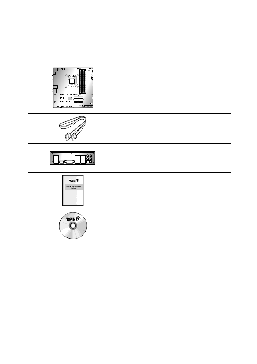
Check the box contents!
The retail motherboard package should contain the following:
1 x S5545 Motherboard
2 x SATA Cable
1 x Rear IO Shield
1 x S5545 Quick reference guide
1 x TYAN
®
Driver’s and Utilities DVD
IMPORTANT NOTE:
Sales sample may not come with the accessory listed above.
Please contact your sales representative to help order accessory for your
evaluation.
4
http://www.tyan.com

Chapter 1: Instruction
1.1 Congratulations
You have purchased the powerful TYAN® S5545 motherboard, based on the
®
Q170 and Nuvoton NCT6683D-T chipsets. The S5545 is designed to
Intel
support single Intel
un-buffered non-ECC UDIMM DDR4 2133MHz memory. Leveraging advance d
technology from Intel®, the S5545 is capable of offering scalable 32 and 64-bit
computing, high-bandwidth memory design, and lightning-fast PCI-E bus
implementation.
The S5545 not only empowers you in today’s demanding IT environment but also
offers a smooth path for future application upgradeability. All of these rich feature
sets provides the S5545 with the power and flexibility to meet demanding
requirements for today’s IT environments.
Remember to visit the TYAN® website at http://www.tyan.com. There you can
find all the information on all TYAN® products as well as all the supporting
documentation, FAQs, Drivers and BIOS upgrades.
1.2 Hardware Specifications
TYAN S5545 (S5545AG2NR)
Processor
Chipset PCH Intel Q170
Memory
Expansion Slots PCI-E
LAN
Storage SATA
®
6th Gen. Core i7/i5/i3 series processor, and up to 64GB of
Supported CPU Series Intel 6th Gen. Core i7/i5/i3 series
Socket Type / Q'ty LGA1151 / (1)
Thermal Design Power
(TDP) wattage
Supported DIMM Qty (4) DIMM slots
DIMM Type / Speed Unbuffered non-ECC UDIMM DDR4 2133
Capacity Up to 64GB
Memory channel 2 Channels
Memory voltage 1.2V
Port Q'ty (2) GbE ports (Intel AMT support)
Controller Intel I210 / Intel I219-LM
Connector (6) SATA
Controller Intel Q170
Speed 6.0 Gb/s
RAID RAID 0/1/10/5 (Intel RST)
Max up to 95W
(1) PCI-E Gen3 x16 slot / (1) PCI-E Gen3 x8 slot
( w/ x4 link) / (1) PCI-E Gen.3 x1 slot
5
http://www.tyan.com
Graphic
Audio
Connector type (1) DVI-D / (2) Display port 1.2
Chipset Intel Processor Graphics(pGFX)
Chipset Realtek ALC892-GR
Feature 5.1 ch
USB
(4) USB 2.0 ports (2 at rear, 2 via cable) / (7)
USB3.0 ports (4 at rear, 2 via cable, 1 TYPE-A)
COM (1) header
Input /Output
Display port (2) Display Port 1.2
DVI (1) DVI-D connector
Audio (1) 5 holes Audio Jack+SPDIF fiber connector
RJ-45 (2) GbE ports
SATA (6) SATA-III connectors
Chipset NCT6683D-T
Fan Total (3) 4-pin headers
System
Monitoring
Temperature
Others Watchdog timer support
AMT Feature
Monitors temperature for CPU & system
environment
Support Power on/ Power off/ Restart at remote
side
Brand / ROM size 16MB
BIOS
Feature
Hardware Monitor / PXE boot support / ACPI 5.0 /
SMBIOS 3.0/PnP/Wake on LAN / ACPI sleeping
states S3,S4,S5
Physical
Dimension
Operating
System
Regulation
Form Factor Micro ATX
Board Dimension 9.6"x9.6" (243.8x243.8mm)
OS supported list Please refer to our Intel OS supported list.
FCC (DoC) Class B
CE (DoC) Yes
Operating Temp. 10° C ~ 35° C (50° F~ 95° F)
Operating
Environment
Non-operating Temp. - 40° C ~ 70° C (-40° F ~ 158° F)
In/Non-operating
Humidity
90%, non-condensing at 35° C
RoHS RoHS 6/6 Compliant Yes
Motherboard (1) S5545 Motherboard
Package
Contains
Manual
Installation CD (1) TYAN installation CD
(1) Web User's manual / (1) Quick Installation
Guide
TYAN S5545-HE (S5545AG2NR-HE)
Supported CPU Series Intel Xeon E3-1200 v5 series processors
Processor
Socket Type / Q'ty LGA1151 / (1)
Thermal Design Power Max up to 80W
6
http://www.tyan.com

(TDP) wattage
Chipset PCH Intel C236
Supported DIMM Qty (4) DIMM slots
DIMM Type / Speed Unbuffered ECC UDIMM DDR4 2133
Memory
Expansion Slots PCI-E
LAN
Storage SATA
Graphic
Audio
Input /Output
System
Monitoring
BIOS
Physical
Dimension
Operating
System
Regulation
Operating Operating Temp. 10° C ~ 35° C (50° F~ 95° F)
Capacity Up to 64GB
Memory channel 2 Channels
Memory voltage 1.2V
(1) PCI-E Gen3 x16 slot / (1) PCI-E Gen3 x8 slot
( w/ x4 link) / (1) PCI-E Gen.3 x1 slot
Port Q'ty (2) GbE ports
Controller Intel I210 / Intel I219-LM
Connector (6) SATA
Controller Intel C236
Speed 6.0 Gb/s
RAID RAID 0/1/10/5 (Intel RST)
Connector type (1) DVI-D / (2) Display port 1.2
Chipset Intel Processor Graphics(pGFX)
Chipset Realtek ALC892-GR
Feature 5.1 ch
USB
COM (1) header
Display port (2) Display Port 1.2
DVI (1) DVI-D connector
Audio (1) 5 holes Audio Jack+SPDIF fiber connector
RJ-45 (2) GbE ports
SATA (6) SATA-III connectors
Chipset NCT6683D-T
Fan Total (3) 4-pin headers
Temperature
Others Watchdog timer support
Brand / ROM size 16MB
Feature
Form Factor Micro ATX
Board Dimension 9.6"x9.6" (243.8x243.8mm)
OS supported list Please refer to our Intel OS supported list.
FCC (DoC) Class B
CE (DoC) Yes
(4) USB 2.0 ports (2 at rear, 2 via cable) / (7)
USB3.0 ports (4 at rear, 2 via cable, 1 TYPE-A)
Monitors temperature for CPU & system
environment
Hardware Monitor / PXE boot support / ACPI 5.0 /
SMBIOS 3.0/PnP/Wake on LAN / ACPI sleeping
states S3,S4,S5
7
http://www.tyan.com

Environment Non-operating Temp. - 40° C ~ 70° C (-40° F ~ 158° F)
In/Non-operating
Humidity
RoHS RoHS 6/6 Compliant Yes
Motherboard (1) S5545 Motherboard
Package
Contains
Manual
Installation CD (1) TYAN installation CD
90%, non-condensing at 35° C
(1) Web User's manual / (1) Quick Installation
Guide
1.3 Software Specifications
For OS (operation system) support, please check with TYAN® support for latest
information.
8
http://www.tyan.com

Chapter 2: Board Installation
You are now ready to install your motherboard.
How to install our products right… the first time
The first thing you should do is reading this user’s manual. It contains important
information that will make configuration and setup much easier. Here are some
precautions you should take when installing your motherboard:
(1) Ground yourself properly before removing your motherboard from the
antistatic bag. Unplug the power from your computer power supply and
then touch a safely grounded object to release static charge (i.e. power
supply case). For the safest conditions, MiTAC recommends wearing a
static safety wrist strap.
(2) Hold the motherboard by its edges and do not touch the bottom of the
board, or flex the board in any way.
(3) Avoid touching the motherboard components, IC chips, connectors,
memory modules, and leads.
(4) Place the motherboard on a grounded antistatic surface or on the antist ati c
bag that the board was shipped in.
(5) Inspect the board for damage.
The following pages include details on how to install your motherboard into your
chassis, as well as installing the processor, memory, disk drives and cables.
NOTE: Do not apply power to the board if it has been damaged.
http://www.tyan.com
9
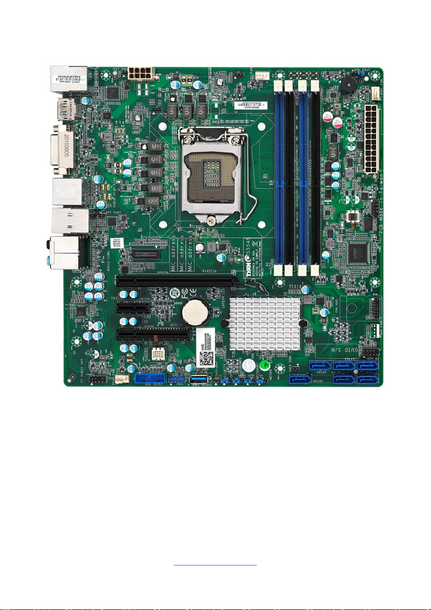
2.1 Board Image
S5545
This picture is representative of the latest board revision available at the time of
publishing. The board you receive may not look exactly like the above picture.
http://www.tyan.com
10

2.2 Block Diagram
S5545 Block Diagram
http://www.tyan.com
11
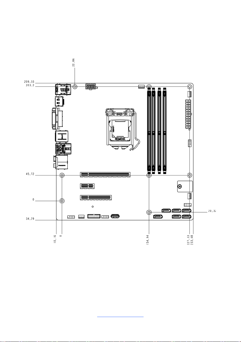
2.3 Mainboard Mechanical Drawing
http://www.tyan.com
12
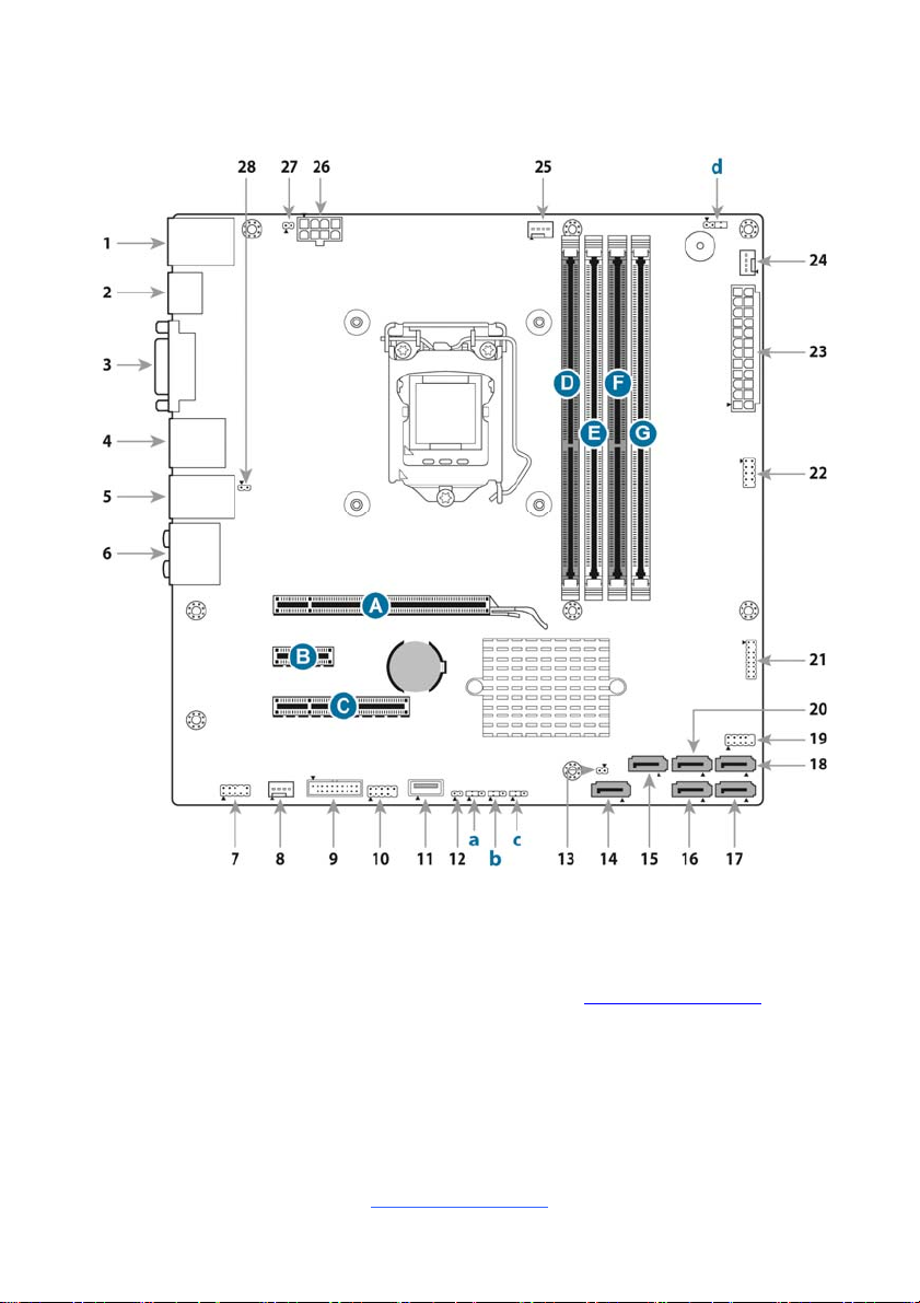
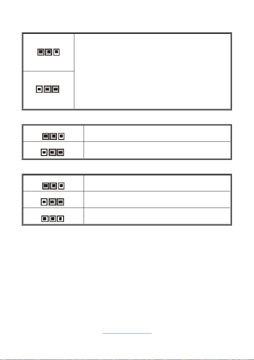
2.4 Board Parts, Jumpers and Connectors
This diagram is representative of the latest board revision available at the time of
publishing. The board you receive may not look exactly like the above diagram. But
for the DIMM number please refer to the above placement for memory installation.
For the latest board revision, please visit our web site at http://www.tyan.com.
http://www.tyan.com
13
Jumpers & Connectors
Connector/Jumper
1 RJ45 LAN Port #1 (LAN1) + USB
2.0 Ports (J42)
2 DP1 (J10) 16 SATA 3 (J39)
3 DVI-D Connector (DVI-D) 17 SATA 1 (J41)
4 DP2/USB 3.0 High Rise (J8/J13) 18 SATA 0 (J50)
5 RJ45 LAN Port #2 (LAN2) + USB
3.0 Ports (J9)
6 Audio Jack (J102) 20 SATA 2 (J47)
7 Audio Front Header (FP_AUDIO_1) 21 TPM Header (DBG_HD1)
8 Rear FAN (J17) 22 COM Header (J77)
9 USB3.0 Header (J26) 23 24-pin Power Connector (J18)
10 USB2.0 Header (FP_USB_3) 24 Front FAN (J20)
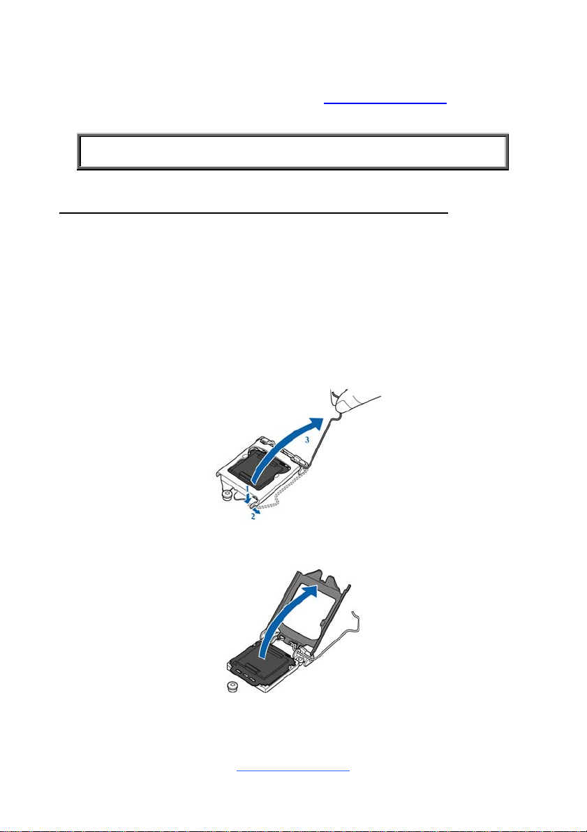
11 USB3.0 Type A (J193) 25 CPU FAN (J16)
12 Intruder (INTRD1)
13 SATA DOM Power Connector
(J83)
14 SATA 5 (J40) 28 LAN2 LED (J82)
Jumpers Slots
a Security Override (J90) A PCIE X16 Slot (PCIE_X16_SLOT1)
b Clear CMOS (J101) B PCIE X1 Slot (PCIE_X1_SLOT1)
c Recovery (J96) C PCIE X8 Slot (PCIE_X8_SLOT1)
d Speaker Header (J85) D DIMM_A0 (J8C1)
Jumper Legend
15 SATA 4 (J48)
19 FP Header (J15)
26 8-pin Power Connector
(PWRCONN1)
27 LAN1 LED (J76)
E DIMM_A1 (J8C2)
F DIMM_B0 (J8C3)
G DIMM_B1 (J8C4)
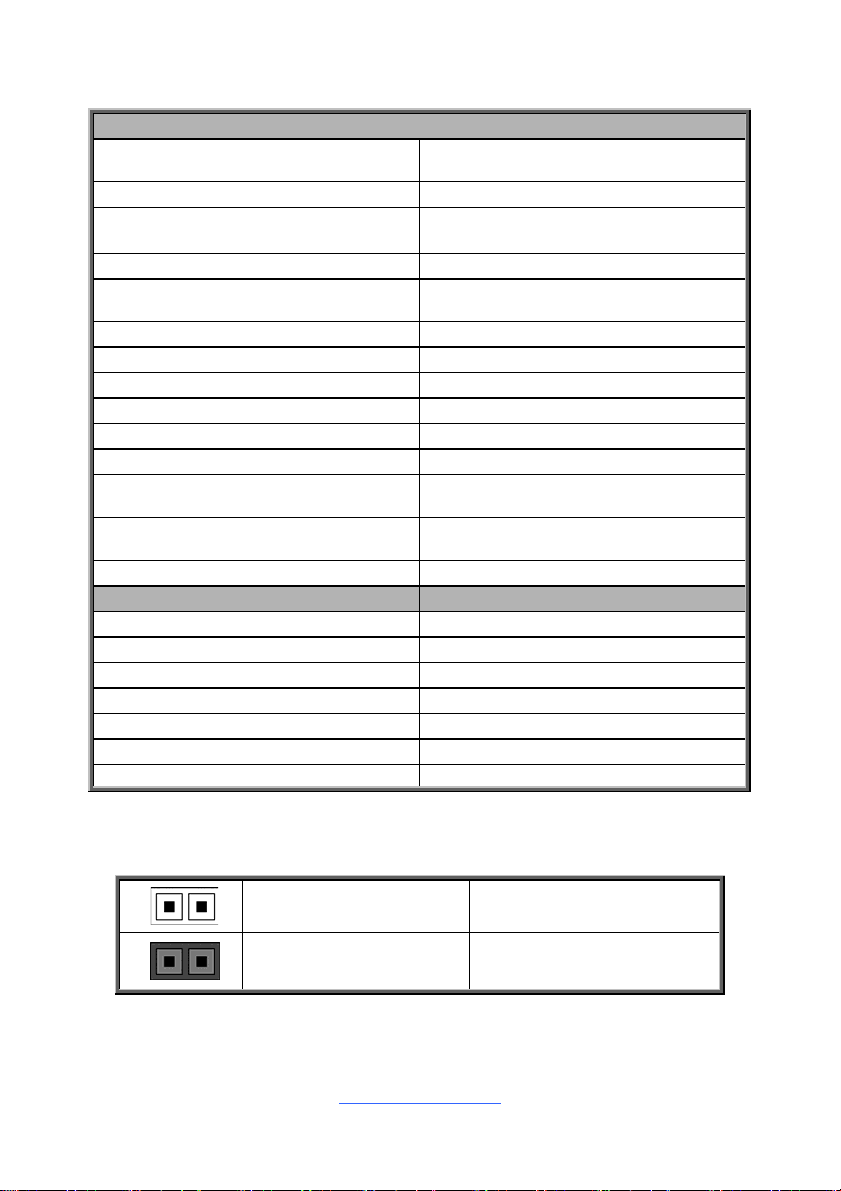
OPEN - Jumper OFF
CLOSED - Jumper ON
14
Without jumper cover
With jumper cover
http://www.tyan.com
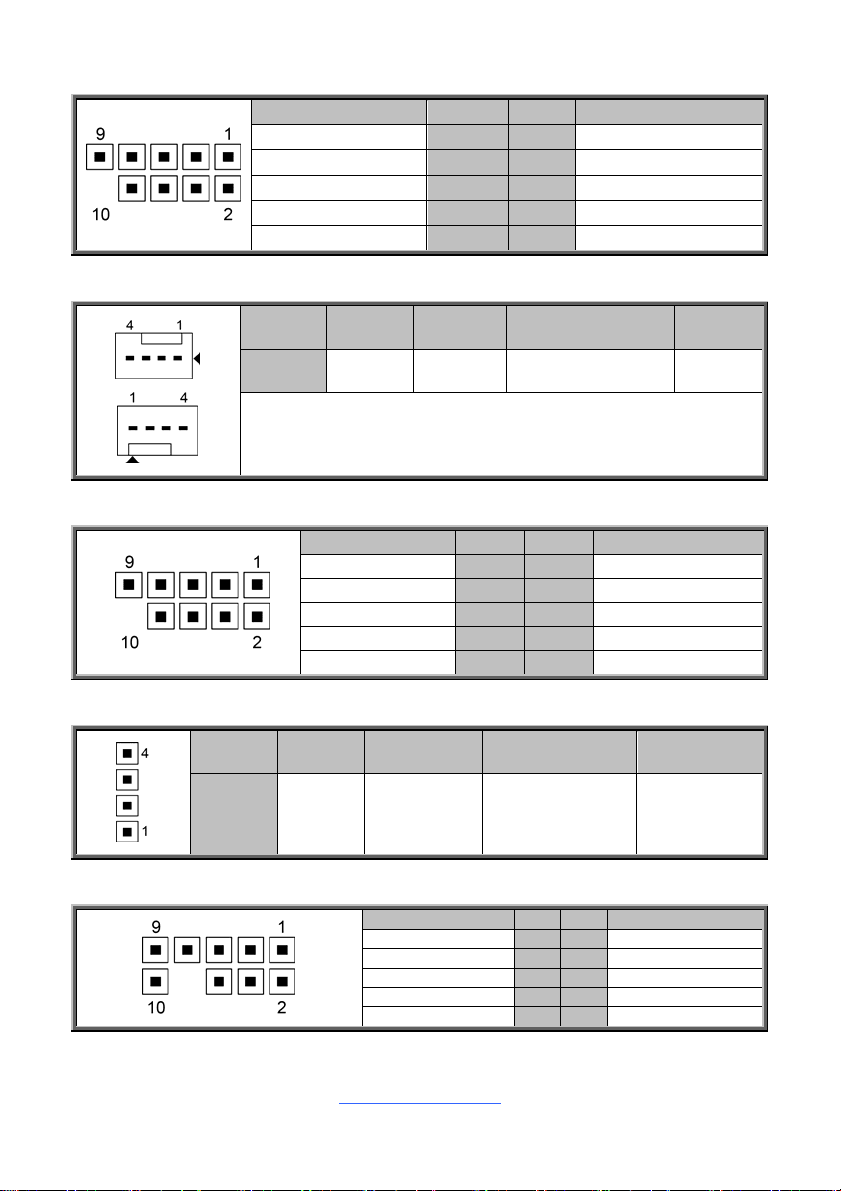
J77: COM Port Header
Signal Pin Pin Signal
DCD 1 2 DSR
RXD 3 4 RTS
TXD 5 6 CTS
DTR 7 8 RI
GND 9 10 KEY-Pin
J16 (CPU FAN) / J20 (Front FAN) / J17 (Rear FAN): 4-pin FAN Connector
Pin 1 2 3 4
Signal GND VCC12 TACHOMETER PWM
Use this header to connect the cooling fan to your motherboard to
keep the system stable and reliable.
J15: Front Panel Header
Signal Pin Pin Signal
VCC5 1 2 GRN BLNK HRD
SATA LED 3 4 YLW BLNK HRD
GND 5 6 PWRBTN
FP RST 7 8 GND
VCC 9 10 NA
J85: Speaker Header
Pin 1 2 3 4
Signal VCC5 FLOATING SPKR_BUZZ_IN SPKR_BUZZ
FP_AUDIO_1: Front Audio Header
http://www.tyan.com
Signal Pin Pin Signal
FP_MIC_L 1 2 AGND
FP_MIC_R 3 4 AUDIO_Detect
AUO_HPOUT_R 5 6 AUO_SENSE_MIC
FIO_SENSE 5 6 NC
AUO_HPOUT_L 7 8 AUO_SENSE_HP
15
J83: SATA DOM Power Connector
Signal Pin Pin Signal
VCC5 1 2 GND
J76: LAN1 LED
Signal Pin Pin Signal
Power 3.3V 1 2 LED Activity
J82: LAN2 LED
Signal Pin Pin Signal
Power 3.3V 1 2 LED Activity
INTRD1: Intruder Header
Signal Pin Pin Signal
GND 1 2 INTRUDER
FP_USB_3: Front USB2.0 Header (blue)
Signal Pin Pin Signal
VCCUSB_13 1 2 VCCUSB_13
USB_PCH_DN1_R 3 4 USB_PCH_DN3_R
USB_PCH_DP1_R 5 6 USB_PCH_DP3_R
GND 7 8 GND
10 NA
SATA0 (J50) / SATA1 (J41) / SATA2 (J47) / SATA3 (J39) / SATA4 (J48) / SATA5
(J40) : SATA3 6G Connector
PIN Define Pin
1 GND
2 SATA TX DP
3 SATA TX DN
4 GND
5 SATA RX DN
6 SATA RX DP
7 GND
Connects to the Serial
ATA ready drives via
the Serial ATA cable.
NOTE: SATA5 (J40)
supports SATA DOM
Device.
16
http://www.tyan.com
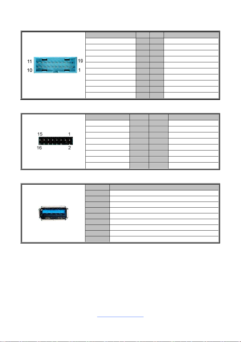
J26: USB3.0 Header
Signal Pin Pin Signal
1 VCCUSB3_FRONT
VCCUSB3_FRONT 19 2 USB30RX_4N_R
USB30RX_3N_R 18 3 USB30RX_4P_R
USB30RX_3P_R 17 4 GND
GND 16 5 USB30TX_4N_R
USB30TX_3N_R 15 6 USB30TX_4P_R
USB30TX_3P_R 14 7 GND
GND 13 8 USB_PCH DN2_R
USB_PCH_DN4_R 12 9 USB_PCH DP2_R
USB_PCH_DP4_R 11 10 USB_PCH_OC24_N_ID
DBG_HD1: TYAN Module Header
Signal Pin Pin Signal
VCC3 1 2 LPC_LFRAME_N
LAD0 3 4 KEY
LAD1 5 6 LPC_RST_N
LAD2 7 8 GND
LAD3 9 10 CLK_24M
SERIRQ 11 12 GND
PRESENT_N 13 14 3V3_VSB
GPIO1 15 16 GPIO2
J193: Vertical Type-A USB3.0 Connector
Pin Signal
1 USB_VCC_TYPE_A
2 USB_PCH_DN8_R
3 USB_PCH_DP8_R
4 GND
5 USB3_PCH_RX5N
6 USB3_PCH_RX5P
7 GND
8 USB3_PCH_TX5N
9 USB3_PCH_TX5P
17
http://www.tyan.com
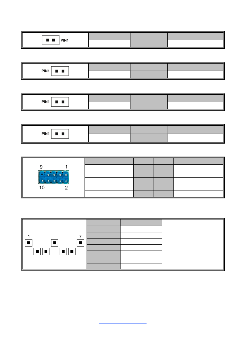
J101: Clear CMOS Jumper
3
3
3
3
3
3
1
Normal (Default)
1
Clear TRC
J90: Security Override Jumper
1
You can reset the CMOS settings by using this jumper. This can be
useful if you have forgotten your system/setup password, or need to
clear the system BIOS setting.
1. Power off system and disconnect power connectors from the
motherboard.
2. Remove the jumper from Pin_2 and Pin_3 (Default setting).
3. Move the jumper cap to close Pin_1 and Pin_2 for several seconds
to Clear CMOS.
4. Put jumper cap back to Pin_2 and Pin_3 (Default setting).
5. Reconnect power connectors to the motherboard and power on
system.
Pin 1-2 Closed: Normal (Default)
1
J96: ME Recovery Jumper
1
Pin 2-3 Closed: Security Override
Pin 1-2 Closed: Normal (Default)
1
31
Pin 2-3 Closed: Configure
Remove Cap: Recovery
http://www.tyan.com
18
2.4 Installing the Processor and Heat sink
The S5545 supported Intel® processors are listed in section 1.2 Hardware
Specifications on page 5. Check our website at http://www.tyan.com for latest
processor support.
NOTE: MiTAC TYAN is not liable for damage as a result of operating an
unsupported configuration.
Processor Installation (SNB_H4 (LGA1151) for Intel Skylake CPU)
Follow the steps below to install the processors and heat sinks.
Please note that the illustrations are based on a SNB_H4 (LGA1151) which may not
look exactly like the motherboard you purchased. Therefore, the illustration s should
be held for your reference only.
NOTE: Please save and replace the CPU protection cap when returning for service.
1. Locate the CPU socket.
2. Pull the CPU lever slightly away from the socket and then push it to a fully
open position.
3. Open the CPU socket cover.
http://www.tyan.com
19
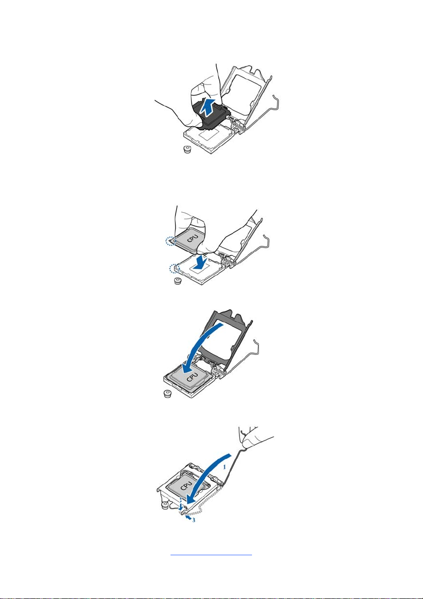
4. Remove the CPU protection cap.
5. Install the processor and make sure the gold arrow is located in the right
direction with two notches properly aligned.
6. Close the CPU socket cover.
7. Press the socket lever down to lock the CPU in place.
http://www.tyan.com
20
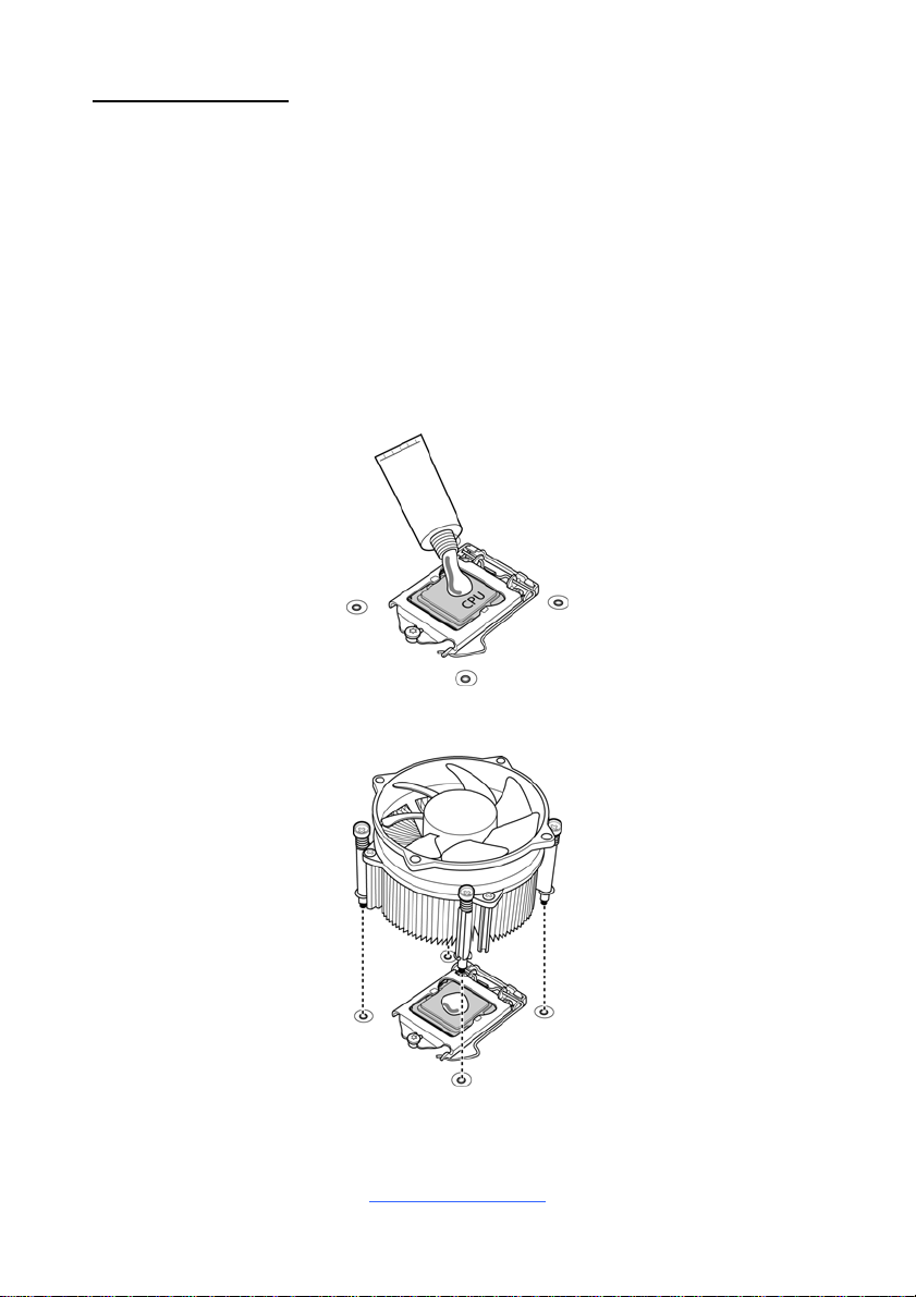
Heat sink Installation
After installing the processor, you should proceed to install the heat sink. The CPU
heat sink will ensure that the processor do not overheat and continue to o perate at
maximum performance for as long as you own them. The overheated processor is
dangerous to the motherboard.
For the safest method of installation and information on c hoosing the appropriate
heat sink, using heat sinks validated by Intel
®
. Please refer to the Intel® website:
http://www.intel.com
The following diagram illustrates how to install the heat sink for the SNB_H3
(LGA1150) socket.
1. Apply the thermal grease.
2. Place the heat sink on top of the CPU and push the 4 latches in a diagonal
pattern to lock it in place.
21
http://www.tyan.com
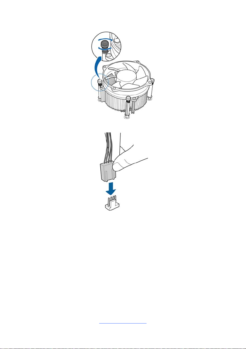
3. Secure the heat sink screws.
4. Connect the fan cable to complete the installation.
http://www.tyan.com
22
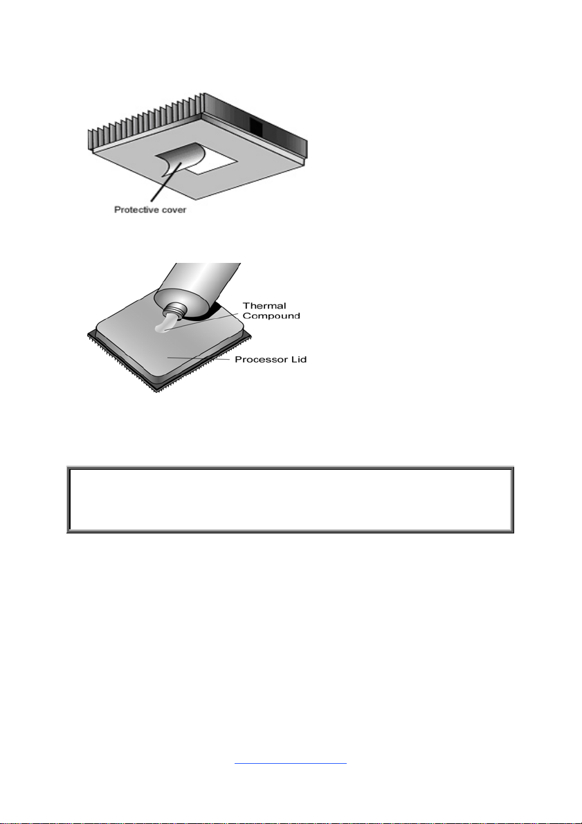
2.5 Thermal Interface Material
There are two types of
thermal interface materials
designed for use with the
processors.
The most common material
comes as a small pad
attached to the heat sink at
the time of purchase. There
should be a protective cover
over the material. Take care
not to touch this material.
Simply remove the protective
cover and place the heat
sink on the processor.
The second type of interface
material is usually packaged
separately. It is commonly
referred to as ‘thermal
compound’. Simply apply a
thin layer on to the CPU lid
(applying too much will
actually reduce the cooling).
NOTE: Always check with the manufacturer of the heat sink & processor to
ensure that the thermal interface material is compatible with the processor
and meets the manufacturer’s warranty requirements.
23
http://www.tyan.com
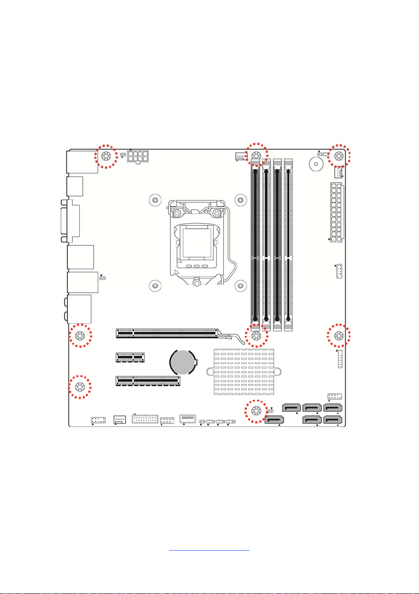
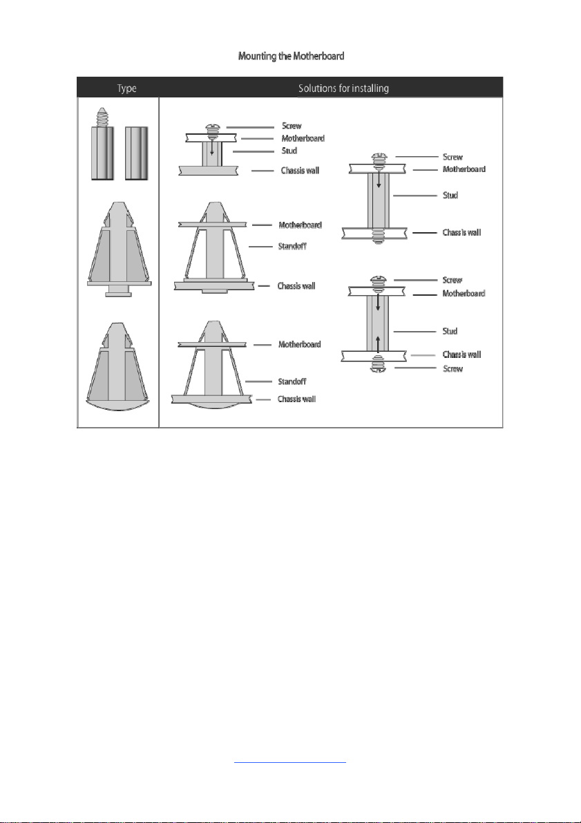
2.6 Tips on Installing Motherboard in Chassis
Before installing your motherboard, make sure your chassis has the necessary
motherboard support studs installed. These studs are usually metal and are gold in
color. Usually, the chassis manufacturer will pre-install the support studs. If you are
unsure of stud placement, simply lay the motherboard inside the ch assis and align
the screw holes of the motherboard to the studs inside the case. If there are a ny
studs missing, you will know right away since the motherboard will not be able to be
securely installed.
Some chassis include plastic studs instead of metal. Although the plastic studs are
usable, MiTAC recommends using metal studs with screws that will fasten the
motherboard more securely in place.
Below is a chart detailing what the most common motherboard studs look like and
how they should be installed.
http://www.tyan.com
24
http://www.tyan.com
25
2.7 Installing the Memory
Before installing memory, ensure that the memory you have is compatible with the
motherboard and processor. Check the TYAN Web site at http://www.tyan.com for
details of the type of memory recommended for your motherboard.
Supports up to 64GB of un-buffered non-ECC UDIMM DDR4 2133MHz
memory
Supports single/dual rank memory
All installed memory will automatically be detected and no jumpers or settings
need changing
All memory must be of the same type and density
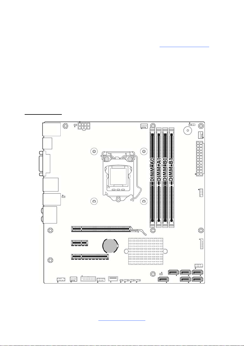
DIMM Location
http://www.tyan.com
26
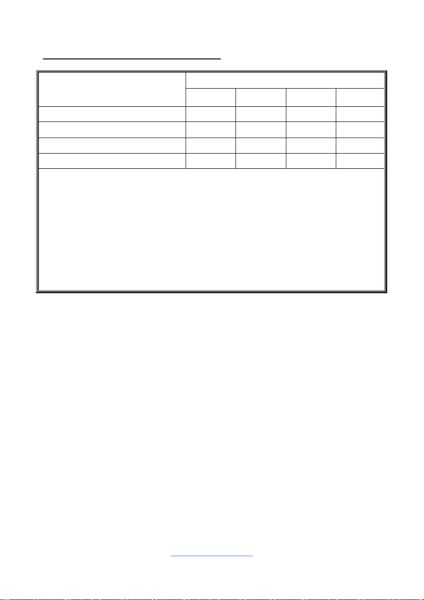
Recommended Memory Population Table
Quantity of memory
installed
DIMM_A0 √ √ √ √
DIMM_A1 √ √
DIMM_B0 √ √ √
DIMM_B1 √
NOTE:
1. √ indicates a populated DIMM slot.
2. Use paired memory installation for max performance.
3. Populate the same DIMM type in each channel, specifically
- Use the same DIMM size
- Use the same # of ranks per DIMM
4. Dual-rank DIMMs are recommended over single-rank DIMMs.
5. Un-buffered DIMM can offer slightly better performance than registered DIMM if
populating only a single DIMM per channel.
6. Always install with DIMM_A0 Slot first.
Single CPU Installed
1 2 3 4
27
http://www.tyan.com
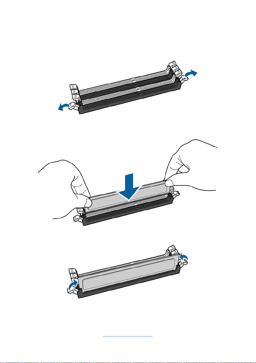
Memory Installation Procedure
Follow these instructions to install memory modules into the S5545.
1. Unlock the clips as shown in the illustration.
2. Insert the memory module firmly into the socket by gently pressing down until
it sits flush with the socket.
3. Lock the clips to secure the memory module into place.
http://www.tyan.com
28
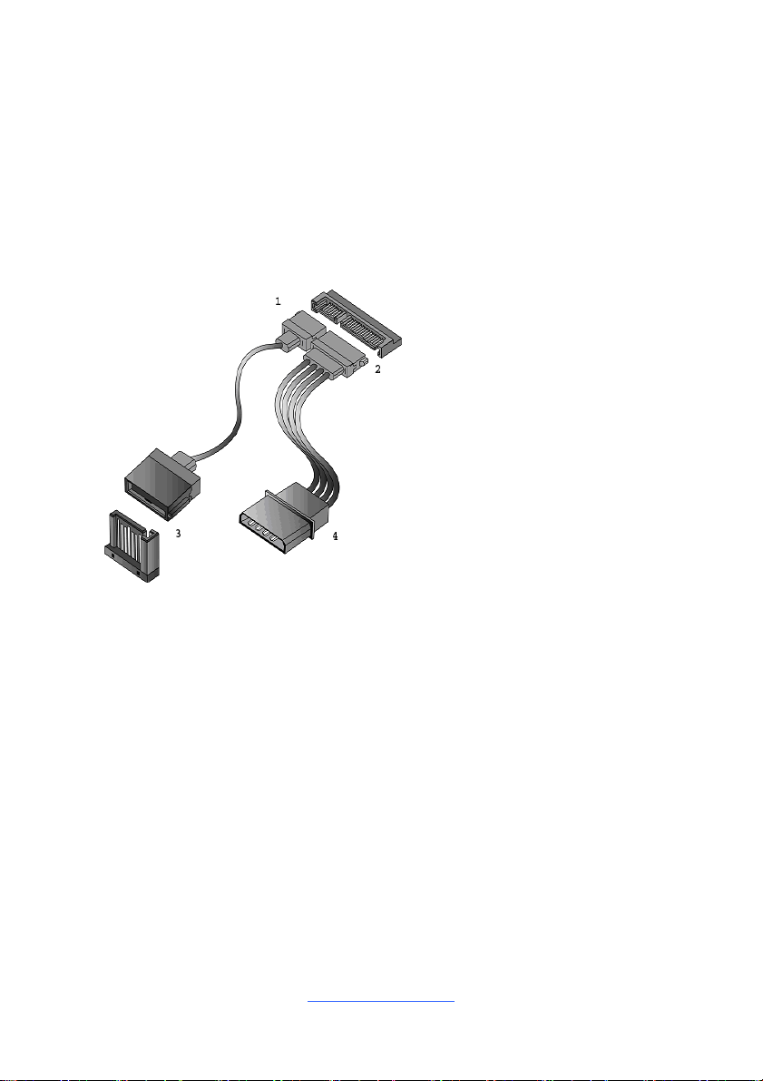
2.8 Attaching Drive Cables
Attaching Serial ATA Cables
S5545 is equipped with six (6) Serial ATA (SATA) channel. Connections for the
drives are very simple.
There is no need to set Master/Slave jumpers on SATA drives.
If you are in need of SATA/SAS cables or power adapters please contact your place
of purchase.
The following pictures illustrate how to connect an SATA drive.
1. SATA drive cable
connection
2. SATA drive power connection
3. SATA cable motherboard
connector
4. SATA drive power adapter
http://www.tyan.com
29
 Loading...