

Page 1
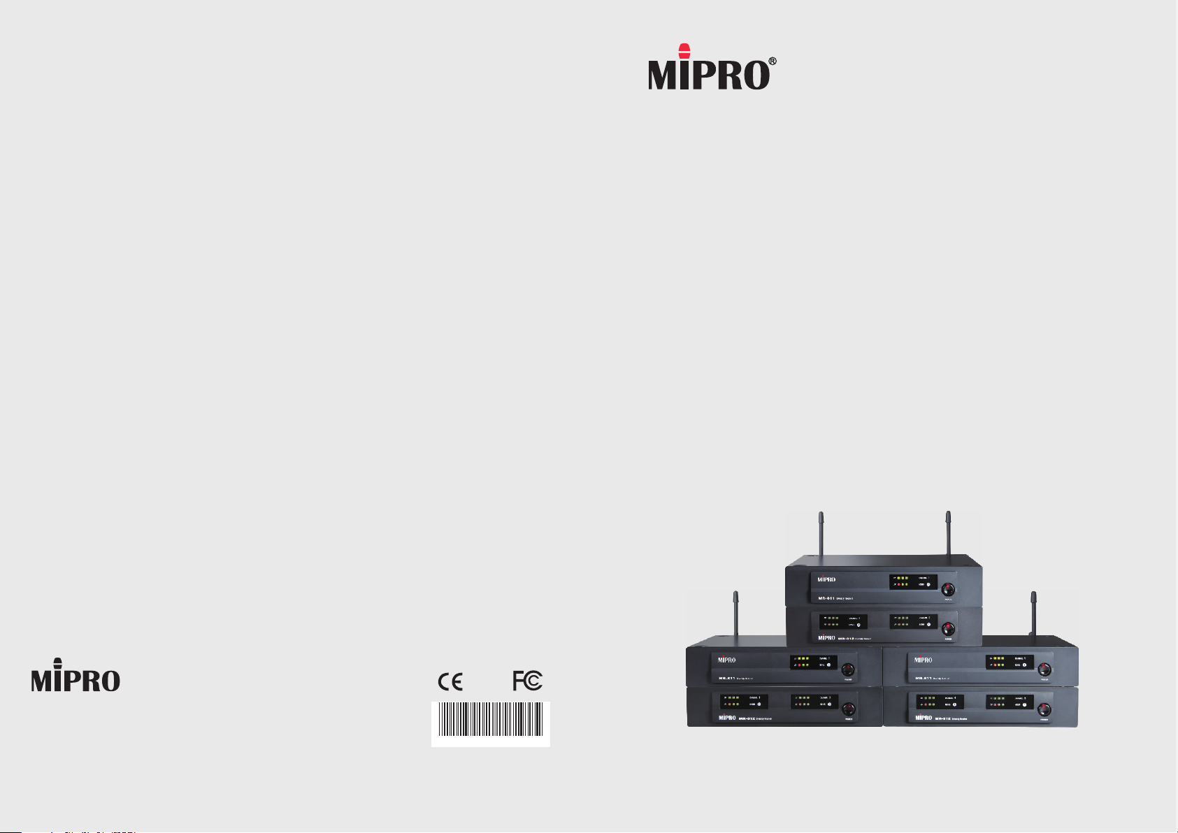
MR-811 / MR-811T
2 CE3 9 7 A
MR-812 / MR-812T
Single/Dual/Quad Channels Diversity Receivers
User Guide
MIPRO Electronics Co., Ltd.
Headquarters: 814 Pei-Kang Road, Chiayi, 60096, Taiwan.
Web: www.mipro.com.tw
E-mail: mipro@mipro.com.tw
Design and specifications are subject to change without prior notice
AS130601
Page 2
! IMPORTANT SAFETY INSTRUCTIONS !
WARNING
1. Read these instructions.
2. Keep these instructions.
3. Heed all warnings.
4. Follow all instructions.
5. Do not use this apparatus near water.
6. Clean only with a dry cloth.
7. Do not block any ventilation openings. Install in accordance with the
manufacturer's instructions.
8. Do not install near any heat sources such as radiators, heat registers,
stoves, or other apparatus (including amplifiers) that produce heat.
9. Do not defeat the safety purpose of the polarised or ground plug: A
polarised plug has two blades with one wider than the other. The wide
blade is provided for your safety. When the provided plug does not fit into
your outlet, consult an electrician for replacement of the obsolete outlet.
10. Protect the power cord from being walked on or pinched particularly at
plug, convenience receptacles, and the point where they exit from the
apparatus.
11. Only use attachments/accessories specified by the manufacturer.
12. Use only with a cart, stand, tripod, bracket, or table specified
by the manufacturer, or sold with the apparatus. When a cart
is used, use caution when moving the cart/apparatus
combination to avoid injury from tip-over.
13. Unplug this apparatus during lightning storms or when unused
for long periods of time.
14. Refer all servicing to qualified service personnel. Servicing is required
when the apparatus has been damaged in any way, such as power-supply
cord or plug is damaged, liquid has been spilled or objects have fallen into
the apparatus, the apparatus has been exposed to rain or moisture, does
not operate normally, or has been dropped.
15. To reduce the risk of fire or electric shock, do not expose this apparatus to
rain or moisture.
16. Apparatus should not be exposed to dripping or splashing and no objects
filled with liquids, should be placed on the apparatus.
17. Use only with the battery which specified by manufacturer.
18. The power supply cord set is to be the main disconnected device.
1. FOR OUTDOOR USE:
To reduce the risk of fire or electric shock, do not expose this apparatus to
rain or moisture.
2. UNDER WET LOCATION:
Apparatus should not be exposed to dripping or splashing and no objects
filled with liquids, such as vases should be placed on the apparatus.
3. SERVICE INSTRUCTIONS:
CAUTION - These servicing instructions are for use by qualified service
personnel only. To reduce the risk of electric shock, do not perform any
servicing other than that contained in the operating instructions unless you
are qualified to do so.
This symbol indicates that dangerous voltage constituting a risk of electric
shock is present within this unit.
This symbol indicates that there are important operating and maintenance
instructions in the literature accompanying this unit.
& IC - ID
THIS DEVICE COMPLIES WITH PART15 OF THE FCC RULES AND RSS-123 ISSUE2 OF
CANADA. OPERATION IS SUBJECT TO THE FOLLOWING TWO CONDITIONS:
(1) This device may not cause interference.
(2) This device must accept any interference, including interference that may cause
undesired operation of the device. This equipment complies with FCC RF radiation
exposure limits set forth for an uncontrolled environment.
Disposal
200 5-08- 13
Dispose of any unusable devices or batteries responsibly and in accordance
with any applicable regulations.
Disposing of used batteries with domestic waste is to be avoided!
Batteries / NiCad cells often contain heavy metals such as cadmium(Cd),
mercury(Hg) and lead(Pb) that makes them unsuitable for disposal with
domestic waste. You may return spent batteries/ accumulators free of
charge to recycling centres or anywhere else batteries/accumulators are
sold.
By doing so, you contribute to the conservation of our environment!
Page 3
Single/Dual/Quad Channels Diversity ReceiversSingle/Dual/Quad Channels Diversity Receivers
Contents
1 Product Overview
3 Receiver Controls and Indicators - Front Panel
5 Receiver Controls and Indicators - Rear Panel
7 Receiver Installation
8 Operation Instructions
9 Rackmount Installation for Receivers
10 Wireless Accessories & Replacement Parts
11 General Tips for Improving System Performance
12 Troubleshooting
Product Overview
For over a decade the MIPRO MR Series systems have been popular in the semiprofessional and karaoke markets. It started with VHF models and then the less
interference, quartz fixed-frequency UHF models quickly replaced the VHF models. MRseries is mass-produced for a period of time. Reliable quality, stable characteristics,
easy to use and affordable price make it ideal choice for entry applications.
MR 8-Series combines the best features of traditional models. It utilizes EIA standard
rack-mountable metal case instead of cheap plastic ones. Innovative modularized design
assembling the PCB, the new clear bright LED control panel and rear panel together
without wiring and adjustment procedures can make several combinations of models to
meet the user's preferences.
This series has advanced RF circuitry and proprietary RF filter to improve antiinterference characteristics and increase more interference-free channels. Advanced
diversity receiving circuit enhances reception distance and eliminates signal drop-out
and interference.
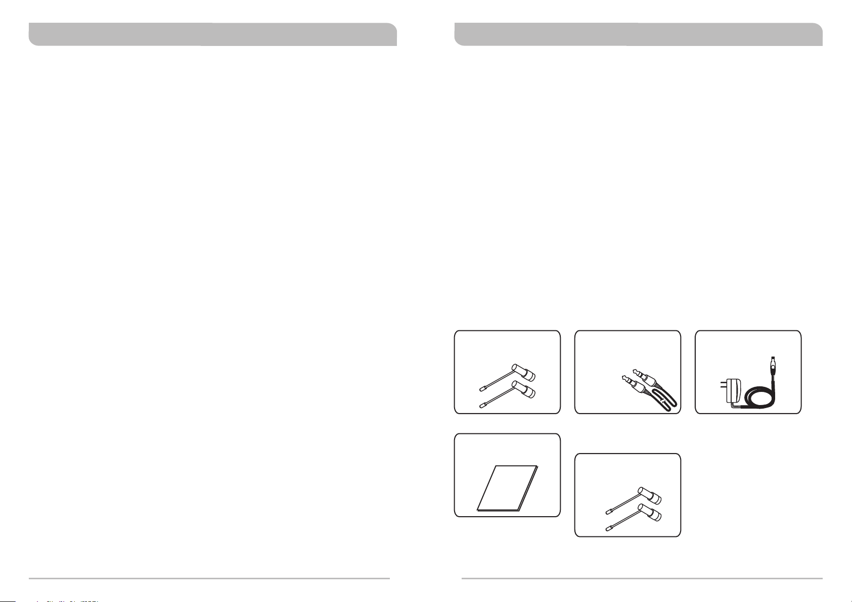
Receiver Accessories Included
Detachable 1/2 Wave
Antenna ×2
Audio Output Cable:
1-pc for MR-811/MR-812
2-pcs for MR-811T/
MR-812T
AC/DC Adapter ×1
User Guide ×1
0
1
Receiver Accessories not Included
Detachable 1/2 Wave
Antenna ×4 (MR-811T/
MR-812T)
Page 4

Single/Dual/Quad Channels Diversity ReceiversSingle/Dual/Quad Channels Diversity Receivers
Receiver Controls and Indicators Receiver Controls and Indicators
Front Panel
MR-811 Single Channel
1
2
MR-812 ual ChannelD
11
22
MR-811T ual Channel (Detachable 1/2 Wave Antenna ×4)D
1
2
MR-812T Quad Channel (Detachable 1/2 Wave Antenna ×4)
43
433
43
Rear Panel
MR-811 Single Channel
MADE IN TAIWAN
DC IN
(12~15V)
5
6
SQ
7 8
0dB
+10dB
-6dB
OUTPUT
LEVEL
9
MR-812 ual ChannelD
MADE IN TAIWAN
DC IN
(12~15V)
5
6
7 8
0dB
+10dB
-6dB
SEPARATE
MIXED
SQ ASQ B
OUTPUT MODE
LEVEL
10
7
9
MR-811T ual Channel (Detachable 1/2 Wave Antenna ×2)D
0dB
-6dB
DC IN
(12~15V)
SQ
OUTPUT
LEVEL
5
6
7 8
9
1
2
43
MR-811T ual Channel (Detachable 1/2 Wave Antenna ×4)D
5
0dB
-6dB
DC IN
(12~15V)
SQ
OUTPUT
LEVEL
6
7 8
9
ANTENNA AANTENNA B
ANTENNA AANTENNA B
11
MADE IN TAIWANMADE IN TAIWAN
MADE IN TAIWANMADE IN TAIWAN
5
ANTENNA AANTENNA B
11
ANTENNA AANTENNA B
OUTPUT AOUTPUT B
8
11
DC IN
(12~15V)
SQ
OUTPUT
6
7 8
DC IN
(12~15V)
SQ
OUTPUT
6
7 8
1212
1212
0dB
+10dB
-6dB+10dB
LEVEL
9
0dB
+10dB
-6dB+10dB
LEVEL
9
ANTENNA AANTENNA B
11
1212
ANTENNA AANTENNA B
11
1212
1111
2222
1
Audio Level Indicators: Indicates transmitted audio signal strength from the
44 3333
transmitters.
2
RF Level Indicators: Indicates received RF (Radio Frequency) signal strength.
3
Noise Warning Indicator: Red light glows denoting the presence of interference.
4
Power On/Off Button: Press and hold button to turn the receiver on and off.
MR-812T Quad Channel (Detachable 1/2 Wave Antenna ×2)
MADE IN TAIWAN
DC IN
(12~15V)
5
6
0dB
+10dB
-6dB
SEPARATE
MIXED
SQ ASQ B
OUTPUT MODE
LEVEL
7 8 8
10
7
9
ANTENNA AANTENNA B
OUTPUT AOUTPUT B
MADE IN TAIWAN
DC IN
(12~15V)
6
7 8 8
0dB
+10dB
-6dB
SEPARATE
MIXED
SQ ASQ B
OUTPUT MODE
LEVEL
10
7
9
ANTENNA AANTENNA B
OUTPUT AOUTPUT B
11
1212
MR-812T Quad Channel (Detachable 1/2 Wave Antenna ×4)
MADE IN TAIWAN
DC IN
(12~15V)
5
6
2
3
0dB
+10dB
-6dB
SEPARATE
MIXED
SQ ASQ B
OUTPUT MODE
LEVEL
7 8 8
10
7
9
ANTENNA AANTENNA B
OUTPUT AOUTPUT B
11
MADE IN TAIWAN
DC IN
(12~15V)
5
6
0dB
+10dB
-6dB
SEPARATE
MIXED
SQ ASQ B
OUTPUT MODE
LEVEL
7 8 8
10
7
9
ANTENNA AANTENNA B
OUTPUT AOUTPUT B
11
1212
Page 5

Single/Dual/Quad Channels Diversity ReceiversSingle/Dual/Quad Channels Diversity Receivers
5
Antenna B Input Connector: To install TNC-type Antenna.
6
DC Input Jack: Accepts +12V DC to +15V DC (center pin is positive and sleeve is
ground).
Squelch Control: This control affects the operating range and signal quality. It is
7
factory pre-set at “+” position and no further adjustment is normally required.
“+”: (Default) High sensitivity and longest operating range.
Adjust counterclockwise (left direction) accordingly to minimize interferences.
However, such action decreases operating range.
8
Unbalanced Audio Output Jack: 6.3mm (1/4”) phone-jack type connector
provides unbalanced audio output signal from this jack to the mixer.
Selectable: “-6dB”、“0dB” or “+10dB”.
9
Unbalanced Level Switch:
0dB - selection is for microphone-level output.
+10dB - selection is for auxiliary level output.
-6dB - selection is for half of cable microphone volume.
10
Unbalanced Mixed Switch:
MIXED - Audio signal from both Channel A & B will be mixed into Output B and no
audio output from Output A.
SEPARATE - Audio signal will be transmitted separately from Output A and Output
B.
11
Antenna A Input Connector: To install TNC-type Antenna.
12
Rack-Mount Brackets (optional): Fits into a standard EIA 19-inch rack case.
Optional MIPRO FBC-71 rear-to-front cables can be installed for front antenna
placement to improve reception quality.
Receiver Installation
MADE IN TAIWAN
DC IN
(12~15V)
5
6
0dB
+10dB
-6dB
SEPARATE
MIXED
SQ ASQ B
OUTPUT MODE
LEVEL
8 8
Antenna Installation:
Install 2 separate antennas on the antenna sockets on the rear panel.
!
Illustrated in Figure 1.
Connecting the power supply:
!
Plug DC plug into the DC-input jack and the power cord, into a power outlet.
6
MR-811T / MR-812T receiver has two DC input jacks. Either is acceptable for
connecting.
Audio output connection:
! Unbalanced Audio Outputs:
! SEPARATE: From output jack B and A.
! MIXED: From output jack B only.
! Electric Guitar/Bass Output:
Switch the Unbalanced Level Switch to "+10dB" position.
! Unbalanced Level Switch :
9
9
! 0dB: Microphone input of a mixer or amplifier.
! +10dB: Electronic guitar/bass.
! -6dB: If audio is distorted due to high vocal or instrument levels.
ANTENNA AANTENNA B
OUTPUT AOUTPUT B
11
(Figure 1)
5
11
4
5
Page 6

Single/Dual/Quad Channels Diversity ReceiversSingle/Dual/Quad Channels Diversity Receivers
Operation Instructions
MADE IN TAIWAN
DC IN
(12~15V)
0dB
+10dB
-6dB
SEPARATE
MIXED
OUTPUT MODE
LEVEL
7 7
SQ ASQ B
1. Turn volume controls of the receiver and mixer in use to a minimum setting before
turn on the microphones or transmitters. After switches on the receiver, the power
switch red indicator illuminates to denote normal power status.
2. If RF LED indicators of the receiver light on before switches on the microphone or
2
transmitter, it indicates the receiver is receiving interference signals. This system
has Pitlotone and NoiseLock dual-squelch features and no noise output will occur. If
multiple channels are used and both RF and AF LEDs glow and interference noise
appear, simply adjust the Squelch controls clockwise until AF signal indicators to
7
extinguish. (Figure 2). However, by adjusting the squelch controls, it affects the
sensitivity level of the receiver, therefore, shorten the operating distance and
decreases the stability.
3. Under normal circumstances, the RF indicator lights up when a microphone or
transmitter is turned on near the receiver to indicate the receiver is ready for
normal operation. Once sounds to the microphone and the AF LED indicators will
glow according to the strength of sound level. If no LED glows or no sound outputs,
the system is not function properly, thus it must be checked.
4. The microphone output level needs to be adjusted at the amplifier or mixer. No need
to adjust at the receiver itself.
ANTENNA AANTENNA B
OUTPUT AOUTPUT B
(Figure 2)
1
Rackmount Installation for Receivers
Half-Rack Unit Receiver
! Install the optional FB-71 rackmount kit & fasten with screws on both sides. (Figure
3)
1-Rack Unit Receiver
! Install the optional FB-72 rackmount kit & fasten with screws on both sides. (Figure
4)
(Figure 3)
(Figure 4)
Receiver Rack-Mount Kits
FB-71 FB-72
Mounts 1 half-rack receiver
into a single rack space
!
The rack mountable kits are pre-drilled with 4 opening holes to be fitted on an EIA
standard 19-inch rack case. (Figure 5)
!
For ideal reception and performance, install the receiver at least 1 meter (3 feet)
above the ground and away from EMI / RFI “noise” sources. In addition, place the
transmitter/microphone at least 1 meter (3 feet) away from the receiving antenna,
as shown. (Figure 6)
Mounts 1 1-rack receiver
into a single rack space
1m
all
W
1m
1m
1m
(Figure 5)
6
7
(Figure 6)
Ground
Page 7

Single/Dual/Quad Channels Diversity ReceiversSingle/Dual/Quad Channels Diversity Receivers
Installation for dual half-rack receivers into a 1-rack unit for
rackmount purpose
! Unfasten screws for each receiver. Push the receivers next to each other.
! Place holding plates on top and bottom of the two receivers first, and following the
directions, slide both plates into position over the screw holes. Then tighten screws.
Place another holding plate on the rear panel and repeat same procedures. (screws
should be used in their original location; i.e., top screws for top holding plate and
bottom screws for bottom holding plate).
! After both receivers are fixed together, fasten the optional rack mount kit on both
sides of the joined receivers as shown in Figure 7.
! Align and install the optional rack mount kit and fasten with screws on both sides.
(Figure 8)
Wireless Accessories & Replacement Parts
FB-71: Rackmount kit fits 1 MR-811 or MR-812 receiver alone.
FB-72: Rackmount kit fits 1 MR-811T or MR-812T receiver alone.
FBC-71: Rear-to-front cables only(1-pair). It allows front mount antenna placement
for improved reception quality.
AT-20: Detachable 1/2 Wave Coaxial Antenna.
AD-707a: UHF 4-channel Wideband Antenna Divider System (480MHz ~ 1GHz).
AD-90W: UHF Wideband Directional Antenna (480MHz ~ 1GHz).
AT-70: UHF Ground Plane Antenna (1-pc, 2-pcs recommended)
AT-70B: UHF Antenna Signal Booster (1-pc, 2-pcs recommended)
AD-90S: UHF 4-Channel Wideband Power Splitter.
AT-90A: UHF 4-Channel Wideband Power Amplifier.
AD-808: UHF 4-Channel Active Antenna Combiner.
(Figure 8)
(Figure 7)
8
9
Page 8

Single/Dual/Quad Channels Diversity ReceiversSingle/Dual/Quad Channels Diversity Receivers
General Tips for Improving System Performance
1. Strive for unobstructed, line-of-sight arrangement between transmitter and receiver
antennas for best operating range. Solid metal objects, electronic equipment &
digital devices in between will usually greatly reduce range.
2. Minimize the distance as much as possible between the transmitter and receiver
antennas for improved reception and system performance.
3. Use supplied antennas and cables to preserve receive sensitivity and minimize signal
loss.
4. Fresh, high-quality alkaline batteries is highly recommended to ensure reliable
transmitter operation as weak or worn-out batteries are common cause of wireless
problems, including failure, poor range, distorted audio and interference.
5. External electrical current should exceed 500mA for MR-811 receiver and 1A for
MR-811T, MR-812 or MR-812T receiver.
6. External DC power supply should not fall under 12V, otherwise it would not work
properly. If it is over 15V, some components of the receiver will be damaged.
7. If extended reception distance is needed, installing a MIPRO AT-90W wideband dual
directional antenna, which includes internal boosters will increase the reception
distance.
8. Proper antenna distribution is vital to achieving ideal performance from multiple
wireless systems operating in the same venue. To greatly reduce antenna clutter in
multi-system installations, a MIPRO AD-707a, UHF antenna divider system is
recommended. Each AD-707a supports up to four UHF diversity receivers to operate
from a single pair of antennas. When combined with an AT-70A omni-directional
extension antenna and an AT-70B antenna booster or an AT-90W wide-band
directional antenna, the AD-707a antenna divider provides optimal signal reception
with minimal dropouts or interference.
9. See “Troubleshooting” section for wireless symptoms and possible solutions.
Troubleshooting
Symptom Solutions
No Sound
Signal Drop-outs
Limited Range
No RF Signal
! Power-on receiver & transmitter.
! Receiver is plugged into a power outlet and cable connected
to mixer/amplifier.
! Fresh batteries in transmitter and inserted with correct
polarity.
! Match receiver & transmitter frequency.
! Close proximity between the transmitter and receiver antenna.
! Line-of-sight path between the transmitter and receiver
antenna.
! Reposition the receiver and/or receiver antennas.
! Receiver antennas are connected.
! Elevate receiver antennas as high as possible.
! Keep hands off of the transmitter antenna.
! Close proximity between the transmitter and receiver antenna.
! Adjust antenna orientation.
! Reposition the receiver and/or receiver antennas.
! Receiver antennas are connected.
! Undamaged antennas.
! Fresh batteries in transmitter.
! Adjust for proper squelch level setting.
! Match receiver & transmitter frequency.
! Adjust for proper squelch level setting.
Notes
! Refer to actual product in the event of product discrepancy.
! Frequency range and maximum deviation comply with the regulations of different
countries.
10
Distortion
11
! Reduce transmitter gain, if set too high.
! Recommendation: set to 0dB (Mic Level).
! Reduce receiver output setting.
! Proper setting on mixer input gain or integrated amplifier mic
level control.
! Fresh batteries in transmitter.
Page 9

Symptom Solutions
Single/Dual/Quad Channels Diversity ReceiversSingle/Dual/Quad Channels Diversity Receivers
RF Interference
Feedback
! Press AutoScan button to locate a clear, interference-free
channel.
! Use preset compatible channels in the same group when
operating multiple systems.
! Place receivers away or remove the sources of RF interference
like solid metal objects, electronic equipment & digital devices,
dimmers, effect equipment, motors.
! Avoid operating a frequency on a local TV channel.
! A higher squelch setting improves protection against
interference. (however, resulting in limited range)
! Turn off one transmitter, if both transmitters are operating on
the same frequency.
! Fresh batteries in transmitter.
! Turn down the sound system volume.
! Move microphone closer to the performer's mouth.
! Reduce transmitter gain if set too high.
! Position microphone further away from the speakers. Do not
point towards speakers.
! Use right type of microphone for the specific applications.
Uni/Omni, Supercardioid / Cardioid.
! Power off all unused microphones.
12
13
 Loading...