

Page 1
MA-708
Portable Wireless PA System
Portability
Simplicity
Flexibility
User Guide
Page 2

Page 3

IMPORTANT SAFETY INSTRUCTION S
1. Read these instructions.
2. Keep these instructions.
3. Heed all warnings.
4. Follow all instructions.
5. Do not use this apparatus near water.
6. Clean only with a dry cloth.
7. Do not block any ventilation openings. Install in accordance with the manufacturer's
instructions.
8. Do not install near any heat sources such as radiators, heat registers, stoves, or other
apparatus (including amplifiers) that produce heat.
9. Do not defeat the safety purpose of the polarised or ground plug: A polarised plug has
two blades with one wider than the other. The wide blade is provided for your safety.
When the provided plug does not fit into your outlet, consult an electrician for
replacement of the obsolete outlet.
10. Protect the power cord from being walked on or pinched particularly at plug,
convenience receptacles, and the point where they exit from the apparatus.
11. Only use attachments/accessories specified by the manufacturer.
12. Use only with a cart, stand, tripod, bracket, or table specified by the
manufacturer, or sold with the apparatus. When a cart is used, use
caution when moving the cart/apparatus combination to avoid injury
from tip-over.
13. Unplug this apparatus during lightning storms or when unused for long periods of time.
14. Refer all servicing to qualified service personnel. Servicing is required when the
apparatus has been damaged in any way, such as power-supply cord or plug is
damaged, liquid has been spilled or objects have fallen into the apparatus, the
apparatus has been exposed to rain or moisture, does not operate normally, or has
been dropped.
15. To reduce the risk of fire or electric shock, do not expose this apparatus to rain or
moisture.
16. Apparatus should not be exposed to dripping or splashing and no objects filled with
liquids, should be placed on the apparatus.
17. Use only with the battery which specified by manufacturer.
18. The power supply cord set is to be the mains disconnected device.
19. Where the MAINS plug or an appliance coupler is used as the disconnect device, the
disconnect device shall remain readily operable.
20. Maximum operating temperature range is 50°C (122°F).
Note: Battery characteristics may limit this range.
Page 4
WARNING
1. FOR OUTDOOR USE:
To reduce the risk of fire or electric shock, do not expose this apparatus to rain or
moisture.
2. UNDER WET LOCATION:
Apparatus should not be exposed to dripping or splashing and no objects filled with
liquids, such as vases should be placed on the apparatus.
3. SERVICE INSTRUCTIONS:
CAUTION - These servicing instructions are for use by qualified service personnel only.
To reduce the risk of electric shock, do not perform any servicing other than that
contained in the operating instructions unless you are qualified to do so.
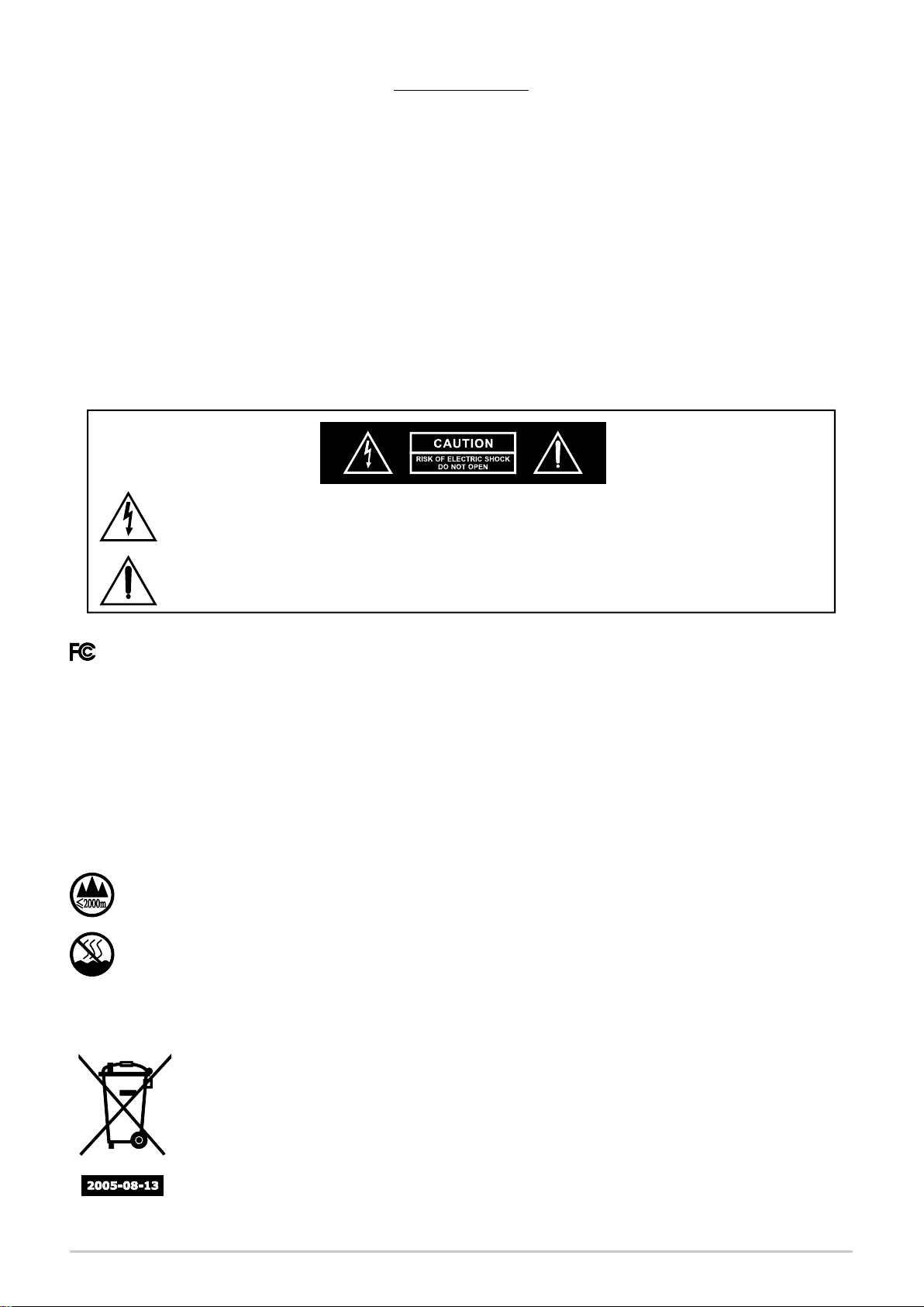
This symbol indicates that dangerous voltage constituting a risk of electric
shock is present within this unit.
This symbol indicates that there are important operating and maintenance
instructions in the literature accompanying this unit.
& IC - ID
THIS DEVICE COMPLIES WITH PART15 OF THE FCC RULES AND RSS-123 ISSUE2 OF
CANADA. OPERATION IS SUBJECT TO THE FOLLOWING TWO CONDITIONS:
(1) This device may not cause interference.
(2) This device must accept any interference, including interference that may cause
undesired operation of the device. This equipment complies with FCC RF radiation exposure
limits set forth for an uncontrolled environment.
“This product can only be used at the area that the altitude is lower than 2000m for
safety purpose.”
“This product can be used in non-tropical locations only for safety purpose.”
Disposal
Dispose of any unusable devices or batteries responsibly and in accordance
with any applicable regulations.
Disposing of used batteries with domestic waste is to be avoided!
Batteries/NiCad cells often contain heavy metals such as cadmium(Cd),
mercury(Hg) and lead(Pb) that makes them unsuitable for disposal with
domestic waste. You may return spent batteries/accumulators free of charge
to recycling centres or anywhere else batteries/accumulators are sold.
By doing so, you contribute to the conservation of our environment!
Page 5
Ⅰ. Part Names
Portable Wireless PA System
COMPACT DISC PLAYER
NOISE
CHANNEL
NOISE
CHANNEL
RF
RF
VOLUME
VOLUME
SCAN
SCAN
SCAN
SENSITIVITYAFACT
SENSITIVITYAFACT
SCAN
NOISE
CHANNEL
NOISE
CHANNEL
RF
RF
VOLUME
VOLUME
SENSITIVITYAFACT
SENSITIVITYAFACT
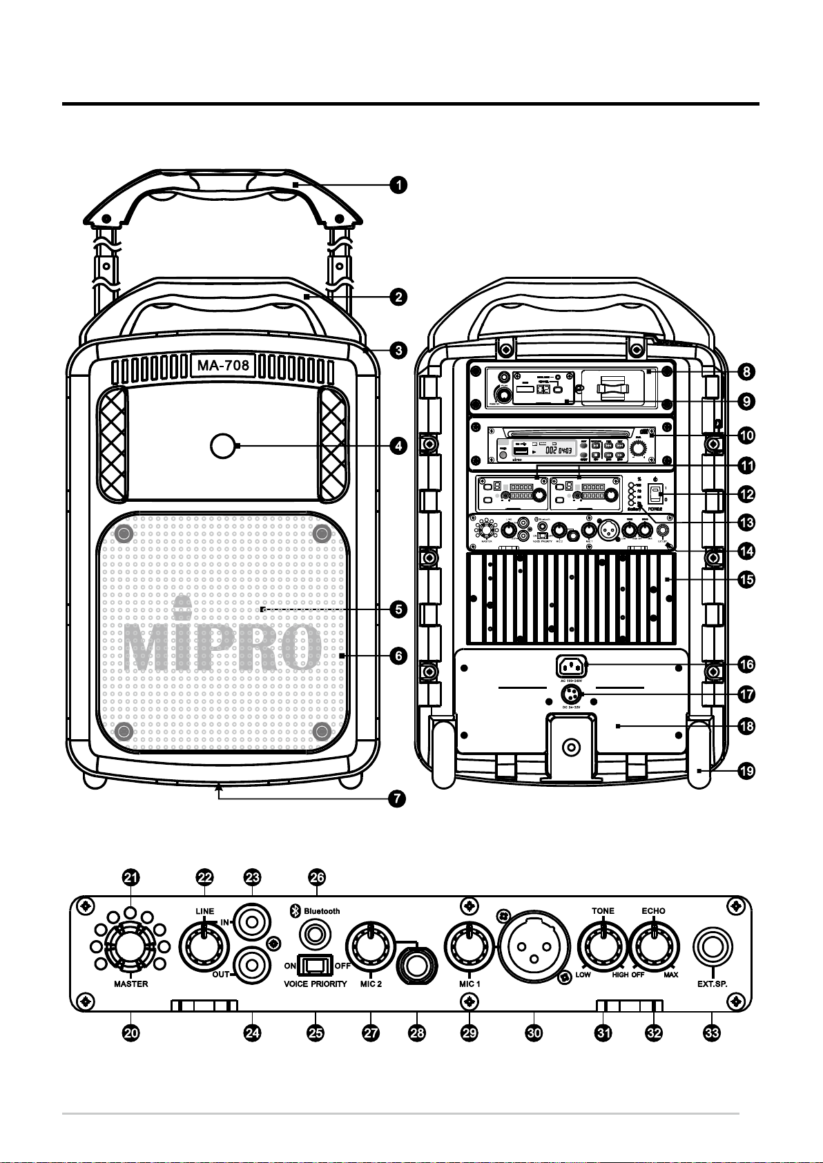
Fig. 1: Front Panel
Fig. 2: Rear Panel
Fig. 3: Control Panel
1
Page 6

Portable Wireless PA System
Front Panel: Fig. 1
Retractable Carry Handle.
Fixed Handle.
Microphone Storage Compartment.
Treble Speaker.
Bass Speaker.
Speaker Grille.
Tripod Stand Mount.
Rear Panel: Fig. 2
Optional Receiver or Interlinking Transmitter Module Frame.
Optional Receiver or Interlinking Transmitter Module.
Optional CD/MP3 Media Player .
Optional Wireless Receiver Module(s).
Master Power Switch.
Battery Status Indicators.
Control Panel.
Heat Sink.
AC Power Cord Socket.
DC Power Connector.
Battery Compartment Cover Plate.
Trolley Wheels.
2
Page 7

Portable Wireless PA System
Control Panel: Fig. 3
Digital Master Volume Control.
Master Volume Indicators.
Line Input Volume Control.
Line Input RCA Jack.
Line Output RCA Jack.
Voice over Music Priority Switch.
Bluetooth Power Button & Indicator.
MIC 2: Unbalanced 6.3 Ø Microphone Input Volume Control.
Unbalanced 6.3 Ø Microphone Input.
MIC 1: Balanced XLR Microphone Input Volume Control.
Balanced XLR Microphone Input.
Tone Control.
Echo Control on Microphones.
Speakon Connector.
3
Page 8

Portable Wireless PA System
Ⅱ. Operating Instructions
1. Power On
. Minimize all volume levels before turning on the Master Power Switch A fully lit
Battery Status Indicators indicates the rechargeable battery is fully charged A single
red color indicator indicates the rechargeable battery is low on power. Simply plug the
supplied power cord into the power socket on the back and the other end into an AC
power outlet to recharge the battery.
.
2. Master Volume Control
(A) Master Volume Control has two switchable modes The standard mode resets to
zero volume level after power is turned off. The memory mode saves and recalls the
last programmed volume level by pressing and holding the specific volume indicator
before power is turned off.
(B) We recommend the master volume control is turned to the maximum level. Next,
adjust volume of other audio input individually to avoid distortion with maximum
dynamic range output. Built-it audio limiter serves automatically to pre
level from exceeding a preset limit and stop sound from distorting.
.
vent the signal
3. Line input and Line output RCA Jacks
(A) Reduce the Line Input volume levels to minimum. Once powered on, adjust
(B) Line Output jack combines all mixed audio Volume levels are individually
- -
master volume levels to maximum, and adjust line input volume to appropriate
level
.
.
adjusted and not related to master volume control.
,
4. Wired Microphone
(A) Reduce microphone volume levels to minimum. Once powered on, adjust master
volume levels to maximum.
(B) Plug an unbalanced 6.3 Ø microphone into Unbalanced 6.3 Ø Microphone Input
and adjust MIC 2: Unbalanced 6.3 Ø Microphone Input Volume Control .
(C) Plug a balanced XLR microphone into Balanced XLR Microphone Input and adjust
MIC 1: Balanced XLR Microphone Volume Control .
(D) Tone Control for high low or Echo Control effect adjustments. /
4
Page 9

Portable Wireless PA System
(E) The Voice over Music Priority feature mutes the volume of the played audio when
it is switched to on and microphone is used Feature is disable it is switched to off
. .
(F) The wired and wired microphones can be used at the same time and sound can be
heard simultaneously.
5. Receiver Module
Part Names, Fig. 4
RF
AF
Fig. 4
Power Volume knob. &
VOLUME
Audio indicators.
Sensitivity level adjustor.
Channel sync ACT window.
Channel sync ACT button .
Channel SCAN button.
Channel LED screen.
Noise interference indicator.
RF indicators.
6. Wireless Microphones
(A) Reduce microphone volume levels to minimum Once powered on adjust master
volume levels to maximum
(B) Power on the receiver module and reduce volume levels to minimum.
. ,
.
(C) Perform the channel synchronization between the receiver and transmitter by
pressing the Channel sync ACT button Once channel is synchronized adjust to
the desired volume levels
.
.
(D) Both wired and wireless microphone has the voice over music priority function .
5
Page 10

Portable Wireless PA System
(E) Operating Instructions:
(1) Scan Automatically for a Non-interference Receiver Channel:
( ) . Press and hold Channel CH button to perform a channel scan Existing channel
blinks to denote it is ready to accept parameter changes During blinking press and
. ,
release Channel button to scan and stop for an open channel This new channel is now
saved If Channel button is not pressed within six blinks, it stops blinking and reverts
back to the existing channel, Fig. .
.
.
5
( ) b existing channel blinks
( ) & c press release
( ) d a new open channel
( ) & a press hold
is saved
Fig. 5
2 :( ) Manually Searching for a Receiver Channel
Press and hold Channel (CH) button to perform a manual channel search. Existing
channel blinks to denote it is ready to accept parameter changes. During blinking, press
and hold Channel button to force the channel to go forward to the next channel in order.
Release Channel button until a desired channel is located. This new channel is now
saved. If Channel button is not pressed within six blinks, it stops blinking and reverts
back to the existing channel, Fig. 6.
( )
( ) & a press hold
( ) b existing channel blinks
( ) & c press hold
d a new forced
channel is saved
Fig. 6
(F)
Reason for Changing a new Channel:
.(1) Noise or interference is heard during a presentation or performance
, , (2) When two or more receiver modules are installed therefore two or more compatible
(G)
Caution
(1) Do not attempt to change a new channel during a performance where two or more
(2) _” “ denotes this channel is currently experiencing interference, therefore, it should be
6
channels are required to be used simultaneously .
:
transmitters microphones are being used simultaneously to avoid interferences with each
other generated by the transmitting microphone signals.
avoided.
/
Page 11

Portable Wireless PA System
(H) ACT Channel Synchronization:
(1) Ascertain both receiver and transmitter are powered on. Press ACT button on receiver
to activate IR (infrared) channel synchronization. Existing channel blinks .
30 (2) Align the ACT sync windows of both transmitter and receiver within cm of each other
for an automated channel synchronization, Fig. 7.
3 ( ) If ACT channel synchronization is performed successfully, the new channel stops
blinking, RF indicators are lit and audio indicators are lit once you speak into the
microphone.
CHANNELAFRFNOISE
SCAN
ACT SENSITIVITY
VOLUME
Fig. 7
or
7. Pairing Bluetooth Receiver
(A) Power on the Bluetooth receiver and bring the mobile device within reception range .
(B) Press & hold the Bluetooth power button & indicator for 3-5 seconds until blue/red
indicator light is flashing intermittently to indicate the receiver is now ready to be
paired.
(C) If indicator is not flashing intermittently or not flashing, repeat by press & hold for
3~5 seconds until blue/red indicator is flashing intermittently.
(D) Search Bluetooth devices and click on “MIPRO MB-xx” for receiver ID. Enter “ ”
when prompted to enter a PIN code. This will cause your device to pair with the
Bluetooth receiver.
(E) Once paired and connection is made, the blue color indicator light on the Bluetooth
receiver will continue to flash intermittently.
& & (F) To cancel Bluetooth function by press hold Bluetooth power button indicator for
0000
3 seconds .
(G) Power off and on the Bluetooth receiver for changing connected device. Repeat the
directions in “Pairing Bluetooth Receiver” to connect a different device.
7
Page 12

Portable Wireless PA System
8Ⅲ. Connection for External Audio Sources, Fig.
MP3 Player
Mixer
CD Player
Amplifier
Mobile Phone
Cassette Player
Wired MIC (Phone Jack)
Part No.: 2FA031
Wired MIC (XLR)
Part No.: 2FA030
Fig. 8
8
Page 13

Portable Wireless PA System
Ⅳ. Operation of Microphone Storage Compartment
1 Two handheld transmitter microphones can be stored in the storage..
2. Storing Transmitters, Fig. 9
(A) Open the lid .
(B) Place the microphone downwards with microphone head pointing up .
(C) Once inserted cover up the lid snugly. ,
Fig. 9
3. Storing Bodypack Transmitters, Fig. 10
(A) Open the lid .
(B) Place the bodypack transmitters downwards with the antenna pointing down.
(C) Once inserted cover up the lid snugly. ,
Fig. 10
9
Page 14

Portable Wireless PA System
Ⅴ. Replace Battery, Fig. 11
1. Remove screws from steel protection cover plate by using a Phillips head
screwdriver not supplied , Fig. 11-1.
2. Tilt slightly gently slowly slide battery away from each battery housing
, &
compartment Remove both color coded wires, Fig. 11-2.
3. Connect red color wire and black color wire (Fig. Ensure the red
-
( )
. -
- - 11-3, 11-4).
color cable is positioned on top, near the “+” terminal. Connect a 3rd cable
(red color) to the terminal socket only for Left Side Compartment when
replacing with MB
4. Insert connected battery into left and right compartment Fasten the screws
once it is covered by steel protection cover plate, Fig. 11-5.
.
-80.
* Note: Each MB-80 battery case holds 4 LFP batteries. 2 MB-80 battery
cases are needed.
Fig. 11-1
Fig. 11-2
Fig. 11-3
Left Side
Compartment
Fig. 11-4
Right Side
Compartment
red
wire
black
wire
no
red
cable
red
cable
black
wire
red
wire
10
Page 15

Portable Wireless PA System
Fig. 11-5
Fig. 11
5. Please only use the following rechargeable internal battery MIPRO MB x ( -70
2 -80 2) , or MB x or an equivalent rechargeable battery of the same type
rating specifications when it is required to be replaced & .
6.
(A) Always change both rechargeable batteries at the same time .
(B) Do not mix battery types and do not mix old and new batteries. Replace both
(C) Replace with the same type and rating rechargeable battery only.
(D) Rechargeable battery can be purchased from authorized MIPRO distributors &
(E) Danger of explosion if battery is incorrectly replaced.
(F) Do not try to heat, ignite, disassemble or throw batteries into a fire.
Manufacturer
Cat No
Rating
C AUTION
batteries at the same time.
dealers.
Kung Long Batteries Industrial Co., Ltd.
WP4.5-12
12 Vdc, 4.5 Ah
11
Page 16

Portable Wireless PA System
Ⅵ. Power Usage Instruction
1. How to use AC power input
(A) After putting the power plug into the AC input socket of the device the battery
(B) AC power provides power to both the unit itself and to the built in lead acid
(C) When using the AC power you can remove or plug the power cord freely with no
, 4
meter indicators will glow immediately no matter if the power switch is on or off
This means that the built in switching power supply is functioning normally and the
built in rechargeable batteries are fully charged If the battery meter indicators are
blinking this means that the built in switching power supply is working normally and
the built in rechargeable batteries are in an under charged condition After a couple
of minutes the battery meter indicators will stop blinking and continue a glowing
condition indicating the batteries are now fully charged
rechargeable batteries
need to turn off the power switch first If or when an unfortunate power cut happens
during usage the MA will activate the DC power automatically to maintain
continuous operation
, .
-
- .
-
- .
,
, .
- -
.
,
.
, -708
.
2. How to use DC power input
(A) Two built in series connection lead-acid batteries with models WP 4.5-12 are used.
-
When the batteries are fully charged, the unit can be operated continuously for
approximately 7 hours in standby mode (CD player and two receivers are turned on);
5~6 hours for audio and 3~5 hours for music The above figures are references for
brand new batteries only
(B) The built in rechargeable batteries can be recharged when the unit is plugged into an
AC or DC power outlet
(C) In the case of no AC power connection if the power switch is not turned on the
battery meter indicators will not be shining When the power switch is turned on
the red LED on it will be shining; meanwhile, if 2 to 4 battery meter indicators are
shining, it means the battery power is enough for normal operation The number of
the shining indicators is in direct proportion of the battery power If only battery
meter indicator is shining or the red LED on the power switch is sparking it means
the battery power is insufficient and immediate charge is necessary If no battery
meter indicators are shining after the power switch is turned on it means the
batteries are completely discharged or possibly faulty
(D) Always store MA system with the batteries fully charged if needing to store the
)
-
.
, ,
. ,
. 1
,
.
,
.
-708
. (
.
12
system for more than months Leave the system plugged into an AC power outlet
when not in use
3 .
.
Page 17

Portable Wireless PA System
(E) The rechargeable batteries will not function properly if not recharged for an extended
(F) If the battery is not used for a long time or not charged properly, even the storage
period of time It is therefore recommended to recharge after every use regardless of
the usage time to preserve battery life
temperature is too high, resulting in excessive discharge and charging failure the first
step is to remove the battery and charge it by V A DC power supply for more
than half an hour and noted the battery surface temperature should not exceed 50
during charging. Then reload it into the machine and turn on the power if the battery
indicator lights a red light connect the AC power for normal charging procedure; if
the battery indicator is completely off which indicates that the battery has failed.
. ,
.
,
18 /2
℃
, ,
,
,
AC power and DC power can not be used at the same time .
A connector is included which allows users to make DC wiring.
See diagram below for illustration.
Connector
DC JACK Diagram
DC V
DC V: 24~32V/10A
Fig. 12
Ⅶ. Selection and Installation of Wireless Receiver Modules
1. Each MA can install two separate wireless receiver modules situated at
the two slots right above the control panel.
2. Installation or replacement of wireless receiver modules, Fig. 13.
(A) Using a Phillips-head screwdriver (not supplied) remove the screws to remove
-708
receiver protection cover panel. (see fig. A & B )
(B) Gently insert the receiver module into the slot Make sure the back edge connector is
aligned and firmly connected see fig. C & D )
(C) Tighten up the screws see fig. E . ( )
.
. (
E
A B
C
D
13
Page 18

Portable Wireless PA System
A
D
B
E
C
Fig. 13
3. Each MA-708 can also install a dual-channel wireless receiver modules
situated at the top slot right above the optional CD/MP3 media player.
MRM /MRM B receiver consists of 2 MRM-70/MRM-70B receiver
-72 -72
modules side-by-side.
4. Installation or replacement of wireless receiver modules, Fig. . 14
(A) Using a Phillips head screwdriver not supplied remove the screws to remove
receiver protection cover panel
(B) Gently insert the receiver module with frame into the slot Make sure the back edge
connector is aligned and firmly connected
(C) Tighten up the screws .
- ( )
.
.
.
MRM-72/MRM-72B
RF
VOLUME
RF
VOLUME
14
AF
AF
MRM-70/MRM-70B MRM-70/MRM-70B
Fig. 14
Page 19

Portable Wireless PA System
Ⅷ. Wireless Interlinking Transmitter and Receiver Modules
1. Users have options to add a single MTM wireless interlinking transmitter
module in this slot The purpose of MTM is to interlink multiple MIPRO
-92
. -92
MA-708 portable PA systems wirelessly to greatly extend the transmission
range and expand coverage.
( ) -92 A MTM Wireless Interlinking Transmitter Part Names, Fig. 15:
Fig. 15
MTM-92 Frame.
Power Switch/Volume Knob.
Channel LED Display.
MT-90/MT-92 transmitter module.
Channel-Selecting Button.
Power Indicator.
Level Limiter Indicator.
Bodypack Transmitter Storage.
(B) Installation of Wireless Interlinking Transmitter:
(1) Using a Phillips head screwdriver not supplied remove the screws to remove protection
(2) Gently insert the transmitter module into the slot Make sure the back edge connector is
(3) Tighten up the screws .
(C) Operating Instructions of MT MT Wireless Interlinking Transmitter: -90/ -92
- ( )
cover panel.
.
aligned and firmly connected
.
(1) Power On Off Turn the transmitter power/volume switch to ON by rotating the knob
clockwise. When ON, the power indicator and Channel LED Display will be lit. Rotate
volume knob clockwise to adjust the desired volume. Rotate same volume knob
counterclockwise to power OFF the transmitter
/ :
.
15
Page 20

Portable Wireless PA System
( ) 2 Select Channels :
( ) a To select a channel one at a time Press and hold the Channel Selecting button for around
( ) b To select channel continuously Press and hold the Channel Selecting button for around
(3) The Level Limiter Indicator will not be lit under normal audio volume. If the audio input
exceeds the set limitations volume restriction control will activate and the indicator will lit
: -
2 seconds and release when channel LED display starts flashing. Press and release button
once to move to the next available channel. If button is not pressed again when Channel LED
flashes 6 times, the channel appearing in Channel Display is automatically saved and set.
: - 2
seconds until channel LED display starts flashing Press and hold same button will
automatically advance channel continuously until stopped There are a total of preset
channels If button is not pressed again when Channel LED flashes times the channel
appearing in Channel Display is automatically saved and set
.
. 16
. 6 ,
.
, .
Adjust volumes to an acceptable level.
(D) MTM Compartment for Bodypack Transmitter:-92
Compartment holds and stores one body pack transmitter, Fig. 16.(1)
Locate and loosen the compartment fastener(2) .
Gently pull the compartment door away from the slot.(3)
Slide the back of the bodypack transmitter into the back of the compartment door in
(4)
position
.
Carefully keep the antenna in horizontal position to prevent from being squeezed(5) .
When secured push in the compartment door back into the slot.(6) ,
Turn fastener counter clockwise to secure the compartment door.(7)
A
D
B
E
C
F
16
Page 21

Portable Wireless PA System
G
Fig. 16
Ⅸ. Installation of MIPRO CD MP Media Player / 3
1. Installation of CD/MP3 Media Player, Fig. 17.
(A) Using a Phillips head screwdriver not supplied remove the screws to remove
protection cover panel
(B) Gently insert the MP3 media player module into the slot. Make sure the back edge
connector is aligned and firmly connected.
(C) Tighten up the screws.
2. Operations of CD MP Media Player See a separate player manual
/ 3 :
- ( )
.
Fig. 17
enclosed in the master carton.
17
Page 22

Portable Wireless PA System
Ⅹ. Helpful Operating Tips
1. We recommend placing sound system between the target audience and the
presenter, facing the audience and raised above their heads using a
speaker stand or tabletop. This set-up helps prevent the annoying feedback
by keeping wireless & wired microphone users behind the sound system.
The internal power supply rechargeable batteries should be kept fully
charged. Always charge the system after use.
2. Minimized the master volume control before powering on. Adjust the
volume controls afterward.
3. Each audio input is accepted through amplifier and its volume can be
controlled separately.
4. Each audio input can be broadcasted and recorded at the same time.
5. NEVER place any wired or wireless microphone in front or close in front of
the speaker otherwise feedback could occur.
6. Do not expose the MA-708 to an environment where there are water
dropping or splashing.
7. This speaker fits into a standard speaker tripod stand.
8. Detached the power cord from AC power outlet once the system is fullyrecharged.
9. Refer to operating instructions for wireless microphone system.
10. Refer to actual product in the event of product description discrepancy.
11. Frequency range, output power and maximum deviation to comply with the
regulations of different countries.
18
Page 23

Page 24

Headquarters: 814 Pei-Kang Road, Chiayi, 60096, Taiwan
MICROPHONE PROFESSIONALS
All rights reserved. MN 019/01
Do not copy or forward without prior approvals MIPRO.
Specifications and design subject to change without notice.
Tel 886.5.238.0809:+
www.m ipro.com . tw
Fax 886.5.238.0803:+
mipro@mipro.com.tw
2 CE5 3 7 D
 Loading...