

Page 1
OPERATINGMANUAL
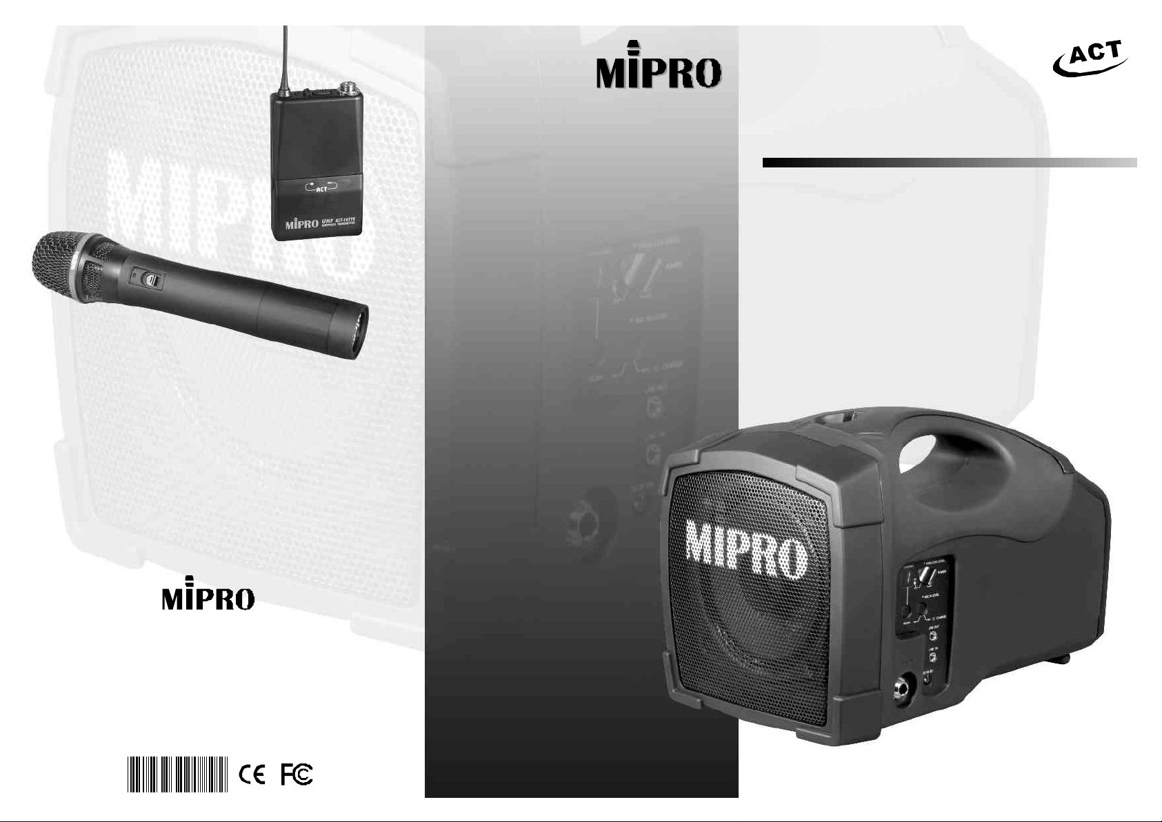
Compact,Mobility,Lightweight,BIGSOUND!
MA-101a
WirelessPortablePAAmplifiers
ElectronicsCo.,Ltd.
Headoffice:814,Pei-KangRoad,Chiayi,60096,Taiwan.
Taipeioffice:5,Lane118,Sung-tehRoad,Taipei,Taiwan.
Web-http://www.mipro.com.twE-mail:@mipro.com.tw
11075,
mipro
Page 2

Contents
WirelessPortablePAAmplifier
WirelessPortablePAAmplifiers
6
INTRODUCTION
6
PARTSNAMEANDFUNCTIONS
6
OPERATINGINSTRUCTIONS
6
CONNECTIONFOREXTERNALAUDIOSOURCES
6
REPLACINGTHEMA-101aBATTERY
6
SWITCHABLECHANNELSFUNCTIONS
6
ACTBUTTON
6
SPECIFICATIONS
--------------------------------------
--------------------------
----------------------------------------
-------------------------------------
HandheldWirelessMicrophone
6
PARTSNAMESANDFUNCTIONS
6
BATTERYINSERTION
6
OPERATINGINSTRUCTIONS
6
CAUTIONS
--------------------------
------------------------------------
BodypacksTransmitter
6
PARTSNAMESANDFUNCTIONS
6
OPERATINGINSTRUCTIONS
6
AF4-PININPUTCONNECTIONMETHODS
6
BATTERYINSTALLATION
6
CAUTIONS
-----
-------------------------------
------------------------
-----------------------
------
------------------
----------------
-----------------
--------------------
-----------------
-----------------
---
----------
1
2,3
3,4
5
6
7
8
8
9
10
10
10
11,12
12
13
14
14
INTRODUCTION
ThankyouforselectingthisMIPROMA-101aWirelessPortablePA
Amplifiersystem.Beforeoperating,pleasereadthisinstructionmanual
carefullyandthoroughlyinordertounderstandthecorrectoperating
procedurestoachievethebestresults.
Don'tbemisledbythecompactsizeofthishighlyefficientportablePA.
Lightweightandpowerful,itcanbehand-carried,shoulder-strapped,setona
flatsurfaceormountedonamicstand.Idealforuseinkindergartensor
primaryschools,placesofworship,presentations,seminars,tradeshows,
auctions,tours,politicaleventsoranyoutdoor/indoorlocationwheregood
qualityspeechannouncementsarearequirement.
Features
■
Workswithonewiredandonewirelessmicrophone.Cable-freeformobility.
■
AvailableinACT-707TE/ACT-707HEtransmitterworkswithoneormoreMA-101a
amplifiers.IdealforsmalleventPA.
■
WorldfirstACTchannelset-uptechnology.16UHFswitchablefrequencies.
■
Lightweightandtrulyportable.
■
Powerfulandclearsoundquality.
■
8hourscontinuousoperationperchargefromitsbuilt-inrechargeablebattery.
■
ConnectstoportableCD/cassette/DVD/MP3playerorotheraudiosourcesto
broadcasthighqualitymusicoverasurprisinglylongdistance.
■
Compatiblewithhandheld,headwornorlavaliermicandguitarinput.
■
Built-instoragecompartments.
■
Reducesvocalfatigue.
■
Amplifiedsoundincreasesattentionspanandimprovescomprehension.
■
Handlescrowdsofupto200people.
Thissystemincludesthefollowingaccessories:
①×AC/DCAdapter1 ②×InstructionManual1
OptionalSC-10carryingbagforMA-101a
0 1
Page 3
WirelessPortablePAAmplifier WirelessPortablePAAmplifier
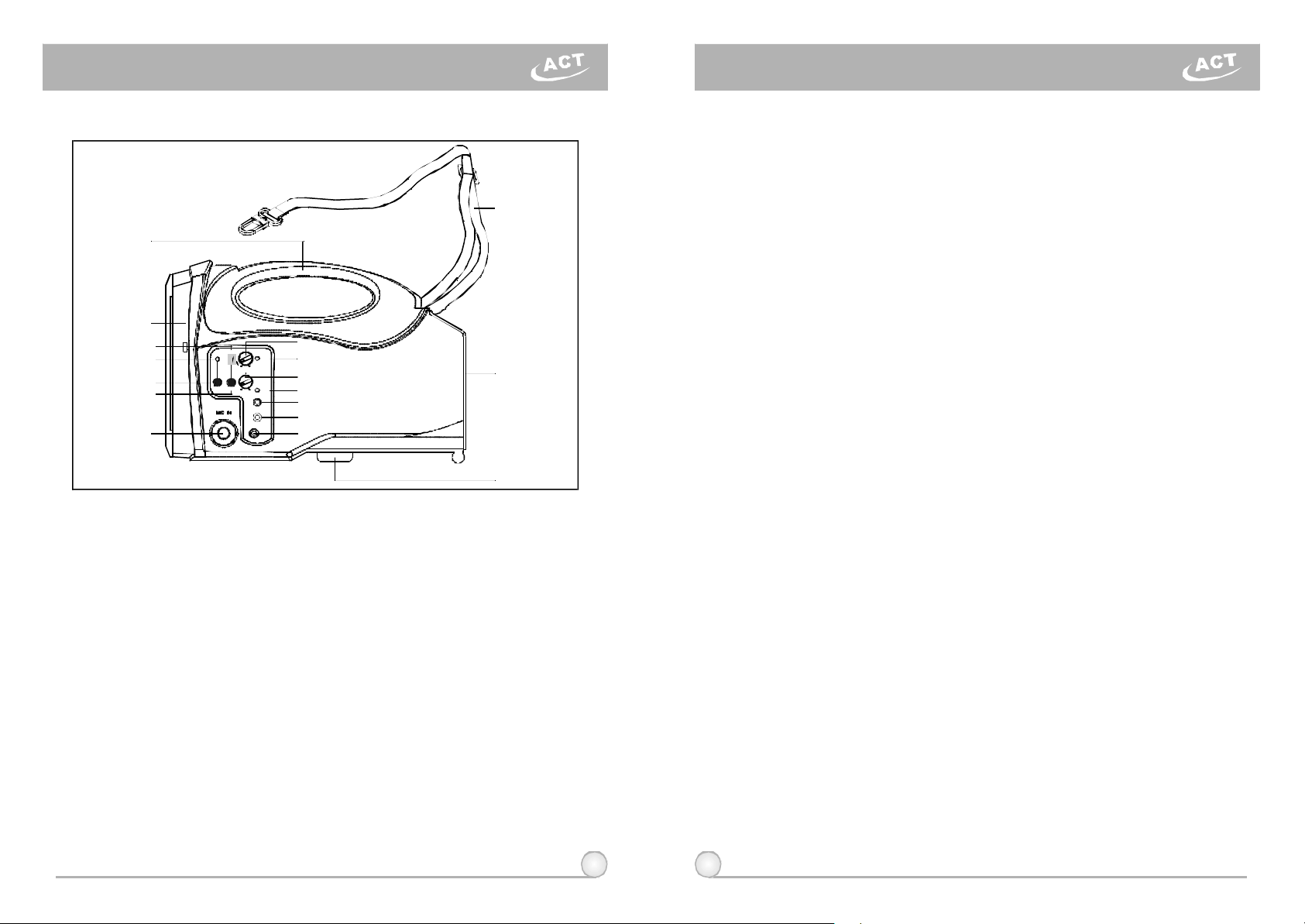
1.PARTSNAMEANDFUNCTIONS
(16)
(1)
(2)
(4)
(5)
(6)
CHARGE
(7)
LINEOUT
(8)
LINEIN
(9)
(10)
(15)
(17)
(18)
(3)
(11)
(12)
(13)
(14)
CHANNEL
ON POWER
OFF MAX
MIN MAX
SCANACT
WIRELESSLEVEL
MICINLEVEL
DCIN18V
(1)FixedHandle:Forconvenientcarryingbyhand.
(2)Speaker:Soundprojectsinthedirectionitispointed.
(3)Mic-InJack:Acceptsa6.3mm(1/4"plugwiredmicrophone.
(4)PowerSwitch/VolumeControl:Turnclockwisepasttheclickforpower-onand
volumecontrolforthewirelessmicrophone.
(5)PowerIndicator:Redlightilluminateswhenpoweristurnedontodenotenormal
powerstatus.GreenlightindicatesaRFlink(itisreceivingsignalfromthe
wirelessmicrophone).
(6)MicrophoneVolumeControl:Volumecontrolforthewiredmicrophone.
(7)ChargingIndicator:
a)Redlightindicatesthebatteryisweakandneedscharging.Chargingtakesaminimum
of4hours.
b)Greenblinkinglightindicateschargingisinprogress.
c)Solidgreenlightindicatesthebatteryisfullycharged.
d)Thissystemisequippedwithanautocut-offcharger.Whenthebatteryisweak(red
light),powerwillcutoffautomaticallytoavoidanydamagethatcouldbecausedbya
powerover-drain.
(8)LineOut:Allowsyoutosendaudiosignal(AF)toanexternalamplifier.
(9)AuxiliaryInputJack:Usesa3.5mm(1/8""minijack"plug.Acceptsexternalaudio
inputs,suchasportablecassette/CD/MP3player.
(10)DCPowerInputJack:PlugintoDCcharger(supplied)forbatterycharging.The
innerconductorispositiveandshouldbeconnectedto18VDC10%,+2.5A.
(11)LEDChannelScreen:Displayscurrentchannel.
(12)ACTPort
(13)ACTButton:Tolockreceiverchannelautomaticallytothetransmitterchannel.
(14)ScanButton:Toautoscanforaclearandinterference-freereceiverchannel.
(15)Body:Housesallelectroniccomponents.
(16)ShoulderCarryBelt:MaybestoredinsidetheBatteryCompartment.
(17)BatteryCompartment:Therechargeablebatteryislocatedbehindthebattery
(18)MicrophoneStandMount:Forconvenientmountingonastandard35mmthreaded
2.OPERATINGINSTRUCTIONS
(1)PersonalWirelessPASystem
(2)BatteryChargingProcedures:
2 3
compartmentdoor.
microphonestand.
a)TurnonPowerSwitch/VolumeControl(4).Redlight(5)shouldilluminate.
b)Turnonwirelesstransmitter.Greenlight(5)shouldilluminate.
c)Adjustvolumelevel(4)clockwisetodesiredloudness.
d)OnewirelessmicrophonecansimultaneouslytransmittomultipleMA-101aunits
receivingonthesamefrequency.However,multiplewirelessmicrophonesofthe
samefrequencycannottransmittoanMA-101areceiveronthatsamefrequency.For
example,ifyouhavebothahand-heldwirelessmicrophoneandabody-pack
transmitteronthesamefrequency,besuretoswitchoffoneofthetwotoavoid
severeinterferencebetweenthem!
a)Pleasemakesurethebuilt-inrechargeablebatteriesarefullychargedbefore
andafteruse.Thebatteryitselfwillgraduallyself-dischargeoveralong
periodoftime.Therefore,ifthesystemwillnotbeusedforalongperiodof
time,pleasemakesurethebatteriesarefullychargedbeforestoringthem
properly.TheCompanywarrantyDOESNOTapplytoover-discharged
batteries;hence,pleaseensurethebatteriesarerechargedevery3months.
b)SimplyplugtheconnectorofthesuppliedDCadaptertotheDC18VPower
InputJack(10)andplugtheotherendintoanyavailableACsocket.
c)Chargingbeginsimmediately,andwillbeindicatedbyaflashinggreenLED.
IfthegreenLEDisnotflashing,itmayduetoexcessivepowerover-drain
anditmaytakelongerforthegreenLEDtoflash.Thisisnormalandnot
faulty.If,afterawhile,thereisstillnoflashinggreenLED,therechargeable
batterymaybefaulty.
d)Ifabatteryreplacementisneeded,openthebatterycompartmentand
exchangethefaultybatteryforanewone.Besuretoinsertthebatterywith
therightpolarityconnection.
e)Thebatteryisanexpendableitem.Undernormaloperation,MIPROoffersa
one-yearlimitedwarranty.
f)Ifyouexperienceashortoperatingtimeafterthebatteriesarefullycharged,
itisoftenanindicationofagingbatteries.Therefore,therechargeable
batteryshouldbereplacedassoonaspossibleatyourearliestconvenience.
Page 4

WirelessPortablePAAmplifier WirelessPortablePAAmplifier
(3)AuxiliaryIn
a)Connectaline-levelsource,suchasportablecassette/CD/MP3playerintothe
Auxinputjack(9).
b)TurnonthePAsystem(4)andadjustvolumeasdesired.
(4)Installation
a)HandCarrying:Removetheshoulderbelt(16)andstoreintheBattery
Compartment(17)directlyabovethebattery.UsetheFixedHandlefor
transport.
b)ShoulderCarrying:Removetheshoulderbelt(16)fromtheBattery
Compartment(17)andhooktheconnectoraroundtherodontopoftheunit,
betweentheFixedHandleandtheSpeaker.
c)MicStandMounting:TheMA-101awillfitdirectlyontopofamicstand
usingthethreadedmount(18)withnoadditionalhardware.Simplyalignthe
holewiththeprotrudingendofthemicstandandthreaditonthestand.
(5)WiredMicrophoneInstructions
a)TurnonPowerSwitch/VolumeControl(4).Redlight(5)shouldilluminate.
b)PlugawiredmicrophoneintotheMicInJack(3).TurnontheWired
MicrophoneVolumeControl(6).
c)Turnclockwisefordesiredloudness(6).
d)TheMA-101aallowssimultaneoususageofbothwiredandwireless
microphones.
(6)AFOutput
AllowstheusertoconnecttheMA-101atoanexternalamplifierwithhigh
poweroutput.ConnecttotheMicInputorLineInputontheamplifier.Usethe
PowerSwitch/VolumeControl(4)tocontrolthevolumelevel.
3. CONNECTIONTOEXTERNALAUDIOSOURCES:
AmplifierMixer
LINEOUT
CableMic.(6.3Connector)φ
Cableno:2FA031
AVAILABLECABLEFROMMIPRO:
MIPRONO:2FA071
3.5φ 3.5φ
LINEINMICIN
MIPRONO:2FA072 MIPRONO:2FA073
6.3φ3.5φ
3.5φ
RCA
CassetteRecorder
I-PODCDPLAYERMP3PLAYER
4 5
Page 5

WirelessPortablePAAmplifier WirelessPortablePAAmplifier
4.REPLACINGTHEMA-101aBATTERY
Withpropercareandcharging,itisunlikelythatitwillbenecessaryto
replacetheMA-101abatteryforsometime.However,thereisanaccesspanel
providedforthispurpose.Ifextendedperiodsofusearerequiredwithouttimeto
rechargethebattery,youmaywishtohaveasecondbatteryfullychargedand
readytoinstallanduseoncetheexistingoneisdrained.Thebatteryisa
standard12V/2.7AgelcellandisavailablefromMIPRO.
1.LaythePAsystemonaflatsurface.
2.Pressdownonthetwofastenersatthetopofbatterycompartment.The
compartmentdoorwillnowswingdownonitshinge.
3.Removetheinteriorrearpanelofthebatterycompartmentbyslidingitup.Use
caution,asthebatterymay"spring"forwardwhenyoureleasethispanel.
Carefullyremovethebattery.
4.Insertafullychargedbattery,observingthecorrectpolarity.Thetwoterminalson
thebatteryshouldbenearthetopofthebatterywiththeprintedsideup.This
alignmentcorrespondswiththespringsandterminalsinsidetheunit.
5.Pressthebatteryintotheunit,holdingitfirmlyagainstthesprings,whilesliding
therearpanelbackintospace.Thismayrequiretwohands.
6.Closethebatterycompartmentdoor.Liftuponthetwofastenersuntilthey"click"
intoplace.
5. SWITCHABLECHANNELFUNCTIONS
1.Functions:
2.HowToSelectaFrequency
3.ChangeChannelWhen:
4.CautionsWhileChangingChannels:
6 7
(a)ThissystemincorporatesadvancedPLLsynthesizedoscillatordesign.Itallows
theusertofreelyselectanyofthe16preprogrammedswitchablefrequencies.
(a)Auto-ScanningFrequencySet-up:PressandholdtheSCANbutton(14)for1
second.ReleasethebuttonwhennumericLED(11)flashes.Thenumeric
numberwillflashatotalof6times.ToactivatetheAutoScanfunction,pressthe
SCANbuttononcewithinthese6times.Aclearfrequencywillautomaticallybe
scannedandsaved/locked.*NotethattheAutoScanfunctionworksonlyduring
thenumericLEDflashing.
Pressandhold"SCAN"button
a)
for1second.
CHANNEL
ON
SCANACT
OFF MAX
MIN MAX
WIRELESSLEVEL
MICINLEVEL
DCIN18V
POWER
CHARGE
LINEOUT
LINEIN
LEDdisplayflashes.
b)
CHANNEL
Press"SCAN"buttonagainandrelease
c)
WIRELESSLEVEL
POWER
ON
OFF MAX
MICINLEVEL
MIN MAX
CHARGE
SCANACT
LINEOUT
LINEIN
DCIN18V
willautoscanforanopenfrequency.
WIRELESSLEVEL
CHANNEL
POWER
ON
OFF MAX
MICINLEVEL
MIN MAX
CHARGE
SCANACT
LINEOUT
LINEIN
DCIN18V
Whendoneitwillautosaved/locked.
d)
WIRELESSLEVEL
CHANNEL
ON
OFF MAX
MICINLEVEL
MIN MAX
SCANACT
DCIN18V
(b)ManualFrequencySet-up:PressandholdtheSCANbutton(14)for1second.
ReleasethebuttonwhenthenumericLED(11)flashes.Thenumericnumber
willflashatotalof6times.Toselectanyofthe16frequenciesintheprogram,
pressandholdtheSCANbuttonuntilthedesiredfrequencyisdisplayed.This
frequencywillautomaticallybesaved/locked.
a)
Pressandhold"SCAN"button
for1second.
CHANNEL
ON
SCANACT
OFF MAX
MIN MAX
WIRELESSLEVEL
MICINLEVEL
DCIN18V
POWER
CHARGE
LINEOUT
LINEIN
b)
LEDdisplayflashes.
CHANNEL
c)
Press"SCAN"buttonandhold,
WIRELESSLEVEL
frequencywillchangeeverytwoflashes.
POWER
ON
OFF MAX
MICINLEVEL
MIN MAX
CHARGE
SCANACT
LINEOUT
LINEIN
DCIN18V
WIRELESSLEVEL
CHANNEL
POWER
ON
OFF MAX
MICINLEVEL
MIN MAX
CHARGE
SCANACT
LINEOUT
LINEIN
DCIN18V
d)
Whendoneitwillautosaved/locked.
WIRELESSLEVEL
CHANNEL
ON
OFF MAX
MICINLEVEL
MIN MAX
SCANACT
DCIN18V
(a)Theexistingchannelisexperiencinginterferenceorisotherwise
malfunctioning.
(b)Selectinganotherchannelformultiplesystemsetup.
(a)WhenmultipleMA-101asystemsareneededtobeusedatthesame
installationascertaintoset-upchanneloneunitatatimebeforeproceed
withthesecondunit.Donotset-upchannelsonallunitssimultaneouslyto
avoidexistingchannelinterference.
(b)WhennumericLEDreaches"_",itindicatesanemptychannelhere.
Proceeduntilanumericnumberappears.
POWER
CHARGE
LINEOUT
LINEIN
POWER
CHARGE
LINEOUT
LINEIN
Page 6

WirelessPortablePAAmplifier
HandheldWirelessMicrophone
6.ACTBUTTON:
Oncethechannelhasbeenselectedonthereceiver,followthesestepsto
programthetransmittertothesamefrequency:
(1)Pressthe"ACT"button(13)onthecontrolpaneloftheMA-101aonceandthe
numericLEDwillflash.Now"ACT"functionisactivatedandreadytoprogramthe
transmitter.
(2)Positionthe"ACT"markingofthetransmitterwithin30cm(12"oftheACTport(12)
facingtowardsthe"ACT"button(13)onthereceiverasillustratedinthefigurebelow.
(3)TheACTfunctionwillbedeactivatedautomaticallyoncethetransmitterfrequencyis
lockedonandnumericLEDstopsflashing.
7.SPECIFICATIONS:
Spec
CarrierFrequencyRange
RX
PowerOutput
FrequencyResponse
OperationMode Directoperationonspeakerunit
PowerSupply
ChargingTime
OperatingTime
Dimensions(m/m)
ExteriorColors
Approvals&Patents
Model
OscillationMode
Max.Deviation
Antenna
Sensitivity
T.H.D.
AudioInput
Speaker
Weight
Note
Built-inwirelessreceiver,1/4"micandline-injacks
Built-in5inchhighsensitivityfullrangespeaker
12/2.7AHrechargeablebatteryandintelligentcharger
4hoursAutomaticrechargeablebatterymanagement()
Newstylepatents;Telecomandsafetyregulationsapproved
Variousspecificationsoncarrierfrequencyranges,maximum
deviationsandRFoutputpowercomplywiththeregulationsof
differentcountries.
MA-101a
UHF600~950MHz
PLL
40KHz
BuiltIn
6dBmVatS/N>70dB
27W(RMS)/4Ω (load)
<1%
50Hz-15KHz3dB±
with90~260VACadapter
8hourstalktime
285(L)x160(W)178(H)x
3Kgs(withbattery)
Black
1.PARTSNAMESANDFUNCTIONS
1 2 3 4 5 6 7 98
(Fig.1)
1.Grille:Protectscartridge,prevents"POP"noiseandpreventsmicrophone
fromrollingwithpolygonalshape.
2.ColorRing:Forfrequencydifferentiation.
3.BatteryStatusIndicator:Indicatespoweron/offandthebatterystatus.
WhenthepowerswitchisturnedON,theredLEDsindicatorflashes
briefly,indicatingnormalbatterystatus.Ifnoflashoccurs,ithaseitherno
batteryorthebatteryisdischargedorinstalledincorrectly.Ifafterpower
ontheindicatorstayslighted,itwarnsthatthebatteryisweakandshould
bereplaced.
4.PowerOn-offSwitch:Slidetheswitchfor power"ON"or"OFF".
5.Housing:Upperportiontobeconnectedtocapsulemoduleandbattery.
Internally,itholdstransmitterPCB.
6.BatteryCompartment:Designedtoaccommodateone9Voltbattery.
7.BatteryCap:Coversbatteryinthebatterycompartment.
8.Anti-rollRing:Forfrequencydifferentiation.
9.ACTSignalReceptor:ReceivingACTsignalandadjustingfrequency
automatically.
8 9
Page 7

HandheldWirelessMicrophone
BodypacksTransmitter
2.BATTERYINSERTION
(Fig.2)
1.Unscrewbatterycapinacounter-clockwisedirection(7).
2.Inserta9Vbatteryintothebatterycompartmentaccordingtothecorrect
polarityasshowninFig.2.Themomentthebatterytouchestheterminals,
theindicatorwillflashbriefly(7).Thismeansthepolarityiscorrect.
However,ifnoflashoccurs,thisindicateswronginsertionorthatthe
batteryisdead.Pleasere-insertthebatteryaccordingtoitscorrect
polarityorexchangeitforafreshbattery.
3.OPERATINGINSTRUCTIONS
1.Whenmicrophoneisswitchedon:
Whenthepowerisswitchedon,theindicatorwillflashbrieflyindicating
normaloperation.
2.DuringUsage:
TheAFLEDindicatoronthereceiverwillilluminateaccordingtothe
audiosignalstrengthfromthemicrophone.
3.Whenthemicrophoneisnotinuse:
Makesurethatyouturnoffthemicrophoneafterusetoextendthe
batterylife.Removethebatteryfromthebatterycompartmentif
microphoneisnottobeusedagainforsometime.Ifarechargeable
batterywasused,takeitoutandrechargeit.
4.CAUTIONS
Undernormaloperation,whenreceiverandtransmitterarepairedtogether
tosetfrequency,microphoneindicator(3)willremainoffafterACTsetupthe
frequency.However,ifindicator(3)isflashing,itmeansreceiverand
transmitterarenotinthesamefrequencyband.Pleasecheckthestickerson
transmitterandreceivertoobserveiftheyaresharingthesamefrequency
bands.
10 11
1.PARTSNAMESANDFUNCTIONS
1
2
3
4
5
10
1.AFInputJack:Connectstoeitherlavaliereorheadsetmicrophone.(See
5waysofconnectiononAFInputConnections)
2.PowerSwitch:SwitchtoONpositionforoperation.SwitchtoOFFposition
whennotinuse.
3.BatteryStatusIndicator:Indicatesthepoweron/offandbatterystatus.
(a)Whenpowerswitchisturnedon:TheLEDindicatorflashesbriefly,
indicatingnormalbatterystatus.
(b)WhenREDlightilluminatesateitherpoweronorduringusage:The
batterylevelislow,therefore,anewbatteryreplacementisthus
necessary.
4.TransmittingAntenna:1/4transmittingantenna.
λ
5.TransmitterHousing:PackagesthePCBandbattery.
6.ACTSignalReceptor:ReceivingACTsignalandadjustingfrequency
automatically.
7.GainControl:Adjuststhedesirousinputgain.
8.GT/MTLevelSelectSwitch:SwitchGTpositionforelectricguitarusage
and"LineIn".GainControlisirrelevantfor"GT".Switchto"MT"for
condensermicrophoneorwiredmicrophone.GainControlworksin"MT"
forinputsensitivityadjusting.
6
7
8
9
(Fig.1)
Page 8

BodypacksTransmitterBodypacksTransmitter
9.BatteryCompartmentandCover:
Accommodatesone9Voltbattery.
10.DetachableBeltClip:Allows360
degreesrotatingtosuittransmitting
angles.Todetachsimplyusea
screwdriverata45degreeangleto
unfasten.seediagram.
(Fig.2)
2.OPERATINGINSTRUCTIONS
1.ToadjustGT/MTSwitch(8),andGainControl(7),simplypushdownboth
snaplocksonthesidesofbatterycoverandflipitbackwardstoexpose
theadjustmentpanel.
2.Beforepoweron,ascertainifsamechannelwassetupforbothreceiver
andmicrophone.Ifnotadjusttosamechannelaccordingly.
3.TheLEDindicatorflashesbrieflywhenpoweronindicatingnormalbattery
status.Ifnoflashoccursithaseithernobattery,thebatteryisdrainedor
installedincorrectly.Changeaccordingly.
4.Plugthemicrophoneconnectorintotheinputjack(1)andtightenthe
connectorscrewbyclockwisedirectionasshownin(Fig.3).
CapsuleConnector
Headset
Lavalier
Theridgeonthe
connectormustmatchthe
indentationonthesocket
wheninserting.”
3.AF4-PININPUTCONNECTIONMETHODS
(1)2-WireElectretCondenserMicrophoneCapsule
PIN
SHIELD
AUDIO
(2)3-WireElectretCondenserMicrophoneCapsule
SHIELD
AUDIO
BIAS
(3)DynamicMicrophone
2 1
3
SHIELD
AUDIO
(4)ElectricGuitar
SHIELD
AUDIO
PIN
PIN
1
4
2
1 3
2
3
4
PIN
1
2
3
4
1
2
3
4
1
2
3
4
1
1
1 3
4
3
2
4
3
2
4
2
4
3
LOW
1
2
OFF ON BATT.
(Fig.3)
12 13
(5)Line-in(Impedance8KATT.10dB)Ω
SHIELD
AUDIO
PIN
1
2
3
4
1 3
4
2
)
(??
Page 9

BodypacksTransmitter
4.BATTERYINSTALLATION
1.Pushingdownbothsnaplocksonthesidesofbatterycovertoopen
batterycover.Takeoutthebatteries.Fig.5).
2.Inserta9Vbatteryintothebatterycompartmentaccordingtothecorrect
polarityasshownin(Fig.6).Thenpushuptoclosethebattery
compartmentasshownin(Fig.6).
(Fig.6)(Fig.5)
PS:Whenthemicrophoneisnotinuse:
Makesurethepowerofthemicrophoneisoff.Ifthemicrophonewillnot
beusedforsometime,pleaseremovethebatteriesfromthebattery
compartmenttoavoidbatteryleakageandresultindamagedbattery
springsandcircuit.
Disposal
Disposetheunusabledeviceaccordingtovalidregulations.
Disposalofspentbatteries/accumulators
Youarerequiredbylawtoreturnallspentbatteries. Disposingofused
batterieswithdomesticwasteisprohibited!
Batteries/NiCadcellscontainingtoxinsaremarkedby
accompanyingsymbolsthatrefertotheprohibitionof
disposalwithdomesticwaste.Thedesignationsforthe
decisiveheavymetalsare:=cadmium,=mercury,
=lead.Youmayreturnspentbatteries/accumulatorsfree
Pb
2005-08-13
ofchargetotherecyclingcentres,ouroutletsoranywhere
elsewherebatteries/accumulatorsaresold.
Bydoingso,youfulfilthelegalrequirementsandcontributetothe
conservationofourenvironment!
CdHg
5.CAUTIONS
Undernormaloperation,whenreceiverandtransmitterarepairedtogether
tosetfrequency,microphoneindicator(3)willremainoffafterACTsetupthe
frequency.However,ifindicator(3)isflashing,itmeansreceiverand
transmitterarenotinthesamefrequencyband.Pleasecheckthestickerson
transmitterandreceivertoobserveiftheyaresharingthesamefrequency
bands.
14 15
 Loading...