

Page 1
Instruction Manual
MA-101
PERSONAL WIRELESS PA SYSTEM
ELECTRONICS CO., LTD.
Page 2

Electronics Co., Ltd.
Head office: 814, Pei-Kang Road, Chiayi, 600, Taiwan.
Taipei office: 5, Lane 118, Sung-teh Road, 100, Taipei, Taiwan.
Web-http: //www.mipro.com.tw
E-mail: mipro@mipro.com.tw
2CE068
Page 3

CONTENTS
PERSONAL WIRELESS PA SYSTEM
6 PART NAMES AND FUNCTIONS----------------- 1,2
6 OPERATING INSTRUCTIONS-------------------- 2,3
6 REPLACING THE MA-101 BATTERY------------ 4
6 SYSTEMS AND SPECIFICATIONS-------------- 5
HANDHELD WIRELESS MICROPHONE
6 PART NAMES AND FUNCTIONS------------------7
6 BATTERY INSTALLATION------------------------- 8
6 OPERATION------------------------------------------ 8
BODY PACK TRANSMITTER
6 PART NAMES AND FUNCTIONS------------------9,10
6 OPERATING INSTRUCTIONS--------------------10,11
6 AUDIO INPUT CONNECTION WIRING DETAIL---12
Page 4
Personal Wireless PA System
Many thanks for your purchasing the MIPRO's wireless
multi-purpose PA system. Before using, carefully read this
manual in order to understand the correct operating methods
and achieve the best result.
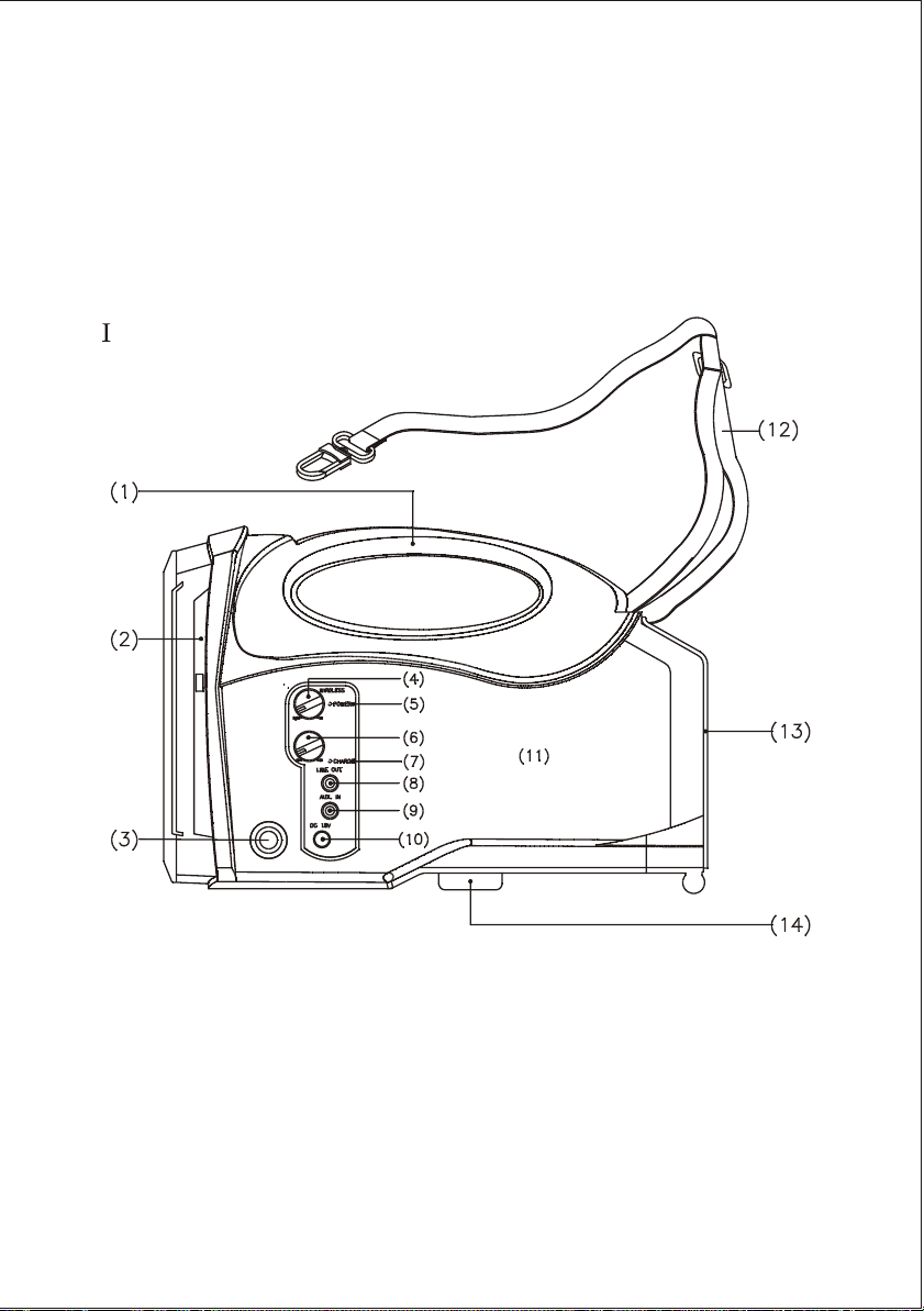
. PART NAMES AND FUNCTIONS
(Fig.1)
(1) Fixed Handle: For convenient carrying by hand.
(2) Speaker: Sound projects in the direction it is pointed.
(3) Mic In Jack: Accepts a 6.3mm plug wired microphone.
(4) Power Switch/Volume Control: Turn clockwise past the
click for power on and volume control for the wireless
microphone.
- 1 -
Page 5

(5) Power Indicator: Red light illuminates when power is
turned on to denote normal power status. Green light
indicates a RF link (it is receiving signal).
(6) Microphone Volume Control: Volume control for the
wired microphone.
(7) Charging Indicator:
Red light indicates the battery is weak and needs
charging. Charging takes minimum 4 hours.
Green blinking light indicates charging is in progress.
Solid green light indicates the battery is fully charged.
This system is equipped with auto cut-off charger.
When battery is weak (red light), power will cut-off
automatically to avoid any damages that could cause by
power over-drain.
(8) Line Out: Allows you to send audio signal (AF) to an
external amplifier.
(9) Auxiliary Input Jack: Uses 3.5mm "minijack" plug.
Accepts external audio inputs, such as portable cassette
and CD players.
(10) DC Power Input Jack: Plug into DC charger (supplied) for
battery charging. The inner conductor is positive and
should be connected to 18VDC 10%, +2.5A.
(11) Body: Houses all electronic components.
(12) Shoulder Carry Belt: May be stored inside the Battery
Compartment.
(13) Battery Compartment: The rechargeable battery is located
behind the battery compartment door.
(14) Microphone Stand Mount: For convenient mounting on a
standard 35mm threaded microphone stand.
- 2 -
Page 6

II. OPERATING INSTRUCTIONS
(1) Personal Wireless PA System
a) Power on Power Switch / Volume Control (4). Red light (5) should
illuminate.
b) Power on wireless transmitter. Greed light (5) should illuminate.
c) Adjust volume level (4) clockwise to desired loudness.
d) One wireless microphone can simultaneously transmit to multiple MA-
101s receiving on the same frequency. However, multiple wireless
microphones of the same frequency cannot transmit to an MA-101
Receiver on that same frequency. For example, if you have both a
hand-held wireless microphone and a body pack transmitter on the same
frequency, be sure to switch off the unused transmitter to avoid severe
interference between the two!
(2) Battery Charging Procedures:
a) Please make sure the inbuilt rechargeable batteries are fully charged
before and after use. Battery itself has such a special characteristic of
self-discharging gradually over a long period of time. Therefore, if the
system will not be used for a long period of time, please make sure the
batteries are fully charged before storing them properly. Company
Warranty DOES NOT apply to over-discharged batteries, hence, please
ensure the batteries are recharged every 3 months.
b) Simply plug the connector of the supplied DC adapter to the DC 18V
Power Input Jack (10) and plug the other end into an available AC
socket.
c) Charging begins immediately, and will be indicated by a flashing green
LED. If the green LED is not flashing, it may due to excessive power
over-drain and it takes longer for the greed LED to flash. This is
normal and not faulty. If after a while and still no flashing green LED,
the battery may be faulty.
d) If a battery replacement is needed, open the battery compartment and
exchange with a new battery. Insert the battery with the right polarity.
e) Battery is an expendable item. Under normal operation, MIPRO offers
one year limited warranty.
f) When experiencing short operating time after batteries are fully charged,
it is often a sign with aging batteries. Both rechargeable batteries must
be replaced at your earliest convenience.
(3) Auxiliary In
a) Connect a line-level source, such as portable cassette or CD player into
the Aux input jack(9).
b) Power on PA system (4) and adjust for volume loudness.
- 3 -
Page 7

(4) INSTALLATION
a) Hand Carrying: Remove the shoulder belt (12) and store in the
Battery Compartment (13) directly above the battery. Use the
Fixed Handle for transport.
b) Shoulder Carrying: Remove shoulder belt (12) from the Battery
Compartment (13) and hook the connector around the rod on top of
the unit, between the Fixed Handle and the Speaker.
c) Mic Stand Mounting: The MA-101 will fit directly on top of a mic
stand using the threaded mount(14) with no additional hardware.
Simply align the hold with the protruding end of the mic stand and
thread it on the stand.
(5) WIRED MICROPHONE INSTRUCTION METHODS
a) Power on Power Switch / Volume Control (4). Red light (5) should
illuminate.
b) Plug a wired microphone into the Mic In Jack (3). Power on Wired
Microphone Volume Control (6).
c) Turn clockwise for desired loudness (6).
d) Allow simultaneous usage of both wired and wireless
microphones.
(6) AF Output
Allows one connecting to an external amplifier with high power
output. Connect to the Mic Input or Line Input on the amplifier. Use Power
Switch / Volume Control (4) for desired loudness.
- 4 -
Page 8

III. REPLACING THE MA-101 BATTERY
With proper care and charging, it is unlikely that it will be necessary to
replace the MA-101 battery. However, there is an access panel provided for
this purpose. If extended periods of use are required without time to
recharge the battery, you may wish to have a second battery fully charged
and ready to install and use once the existing on is drained. The battery is a
standard 12V/2.7A gel cell and is available from MIPRO.
1. Lay the PA system on a flat surface.
2. Press down on the two fasteners at the top of battery compartment. The
compartment door will now swing down on its hinge.
3. Remove the interior rear panel of the battery compartment by sliding it up.
Use caution, as the battery may "spring" forward when you release this
panel. Carefully remove the battery.
4. Insert a fully charged battery, observed the correct polarity. The two
terminals on the battery should be near the top of the battery with the
printed side up. This alignment corresponds with the springs and
terminals inside the unit.
5. Press the battery into the unit, holding it firmly against the springs, while
sliding the rear panel back into space. This may require two hands.
6. Close the battery compartment door. Lift up on the two fasteners until
they "click" into place.
- 5 -
Page 9

. Systems and Specifications:
A. MA-101 Personal Wireless PA Systems:
1. MA-101 Wireless PA System matching with handheld wireless microphone
2. MA-101 Wireless PA System matching with lavaliere wireless microphone
3. MA-101 Wireless PA System matching with headworn wireless microphone
B. MA-101 Primary Specifications:
Spec
TX
&
RX
Frequency Response
Charging Time
Operating Time
Dimension(m/m)
(inch)
Exterior Colors
Model
Carrier
Oscillation Mode
Max. Deviation
Antenna
Sensitivity
Power Output
T.H.D.
Audio Input
Speaker
Power Supply
Weight
Patent
MA-101 UHF Wireless SystemMA-101 VHF Wireless System
VHF 160~250MHz
Quartz-Controlled
15KHz
Built In
12dBmV at S/N > 80dB
27 W RMS / 4 W (load)
<1 %
50Hz-15KHz 3dB
Built-in wireless receiver and
Line-in socket
Built-in 5 inch high sensitivity
Full range speaker
12/2.7AH rechargeable battery
and intelligent charger
with 90~260V AC adapter
4 hours Automatic rechargeable
battery management
8 hours talk time 8 hours talk time
285(L) x 160(W), 178(H)
11.2(L) x 6.3(W) x 7.0(H)
2.95 Kgs / 6.5 lbs. (with battery) 2.95 Kgs (with battery)
Black
Patented
UHF 782~960MHz
Quartz-Controlled
40KHz
Built In
6dBmV at S/N > 70dB
27 W RMS / 4 W (load)
<1 %
50Hz-15KHz 3dB
Built-in wireless receiver and
Line-in socket
Built-in 5 inch high sensitivity
Full range speaker
12/2.7AH rechargeable battery
and intelligent charger
with 90~260V AC adapter
4 hours Automatic rechargeable
battery management
285(L) x 160(W), 178(H)
11.2(L) x 6.3(W) x 7.0(H)
Black
Patented
- 6 -
Page 10

HANDHELD WIRELESS MICROPHONE
PART NAMES AND FUNCTIONS
ON
OFF
3
1
2
4
ON
5
6
5
OFF
7
6
7
8 9
98
(Fig.1)
1. Grille & Screen Assembly: Protects the mic capsule from structural
damage as well as "POP" noise.
2. Capsule Module: It is mainly for protecting the capsule and eliminating
the "POP" sound. This is the main component to transform sound into AF.
3. Anti-Roll Color Ring: Molded polygon shape prevents rolling on flat
surfaces. A variety of colors are available to make Transmitter
identification easy, even at a distance.
4. Microphone Cartridge: Transforms the acoustic signal into an electric
signal.
5. Housing: Durable rubber velvet finish for handling comfort. Upper
portion to be connected to capsule module. Internally, it holds transmitter
PCB and battery compartment.
6. Battery Status Indicator: A brief flash at turn-on indicates that the battery
is OK. No flash at turn-on indicates that the battery is either drained or
not installed correctly. After power-on, a constant glow indicates a weak
battery that should be replaced.
7. Power On-off Switch: Slide up to turn the Transmitter on and slide down
to turn the Transmitter off.
8. Battery Compartment: Accepts a standard/universal 9-volt any type of
battery.
9. Battery Cap: Unscrew battery cap in a counter clockwise direction to
provide access to the Battery Compartment.
- 7 -
Page 11

BATTERY INSTALLATION
++
ONON
OFFOFF
--
(Fig.2)
1. Carefully unscrew, in a counter-clockwise motion, the Battery Cap
(9) from the Housing to export the Battery Compartment.
2. Insert a 9-volt battery, taking care to observe the correct polarity.
3. Screw the Battery Cap back into place turning clockwise, taking
care not to force the turns or cross-tread.
4. If polarity is inserted correctly, the battery status indicator lamp(6)
will flash briefly when the mic is turned on. If no flash is observed,
then it is likely the polarity is incorrect or the battery is dead.
OPERATION
1.Battery Status Indicator: will flash briefly when the microphone is
turned on to denote normal status.
2.The Power Indicator on the PA system will turn from red to green
after the microphone is turned on to denote normal status.
3. Power off the microphone when not in used to extend the life span
of the battery. Take out the 9-volt battery when certain it will not
be use for an extended period of time to avoid leaking of conducive
battery liquid and damage the battery spring and its internal PCB.
- 8 -
Page 12

Body Pack Transmitter
PARTS NAMES AND FUNCTIONS
(UHF TRANSMITTER)
2
MICANT.
(PHONE JCAK)
MIC
1
LOCK
4
VOLUME
5
12
8
9
ON
OFF
10
BATT.LOW
6
7
12
11
(4 PIN JACK)
2
GAINMTGT
8
9
10
MIC
OFF ON
BATT.LOW
3
6
GAINMTGT
7
12
11
8
9
OFF ON
10
BATT.LOW
(Fig.2)
1. Audio Input Connector: Phone-jack connector accepts lavalier and
head worn microphones.
2. Audio Input Connector: 4-pin MIPRO connector accepts a variety of
input levels (consult the 5 audio input connection wiring detail.
Diagram 3).
3. Transmitter Antenna: 1/4 transmitting antenna.
4. Fixed Volume Switch: When slide up, it will lock the volume at fixed
level.
5. Volume Control: Adjusts the volume level.
6. GT/MT Level Selector Switch: Set this switch to GT (Guitar) position
if you are connecting to the output of an electric guitar. Set the switch
to the MT (microphone) position for al other connections.
7. Input Gain Control: Works only in the MT (microphone) position,
giving the user input level control.
8. Transmitter Housing: Lightweight, compact, durable high-impact
plastic for maximum comfort. Contains the PCB and other components.
9. Battery Status indicator: Glows briefly at turn-on to indicate that the
battery is OK. No flash at turn-on indicates that the battery is either
drained or not installed properly. A constant glow indicates a weak
battery that should be replaced.
11
- 9 -
Page 13

10. Power Switch: Turns power to the Transmitter "on" and "off".
11. Battery Compartment and Cover: Accept a 9-volt alkaline battery.
12. Detachable Belt Clip: To detach for pocket use, push in the
direction of the arrow while lifting up on the tab. To install:
Align the flanges on the clip with the tracks on the Transmitter.
Slide the clip upward the connector until it snaps into place.
Operating Instructions
1. Push down and in the direction of the arrow on the battery cover
to open the compartment, as shown in Fig. 1.
2. Insert one piece 9-volt alkaline battery according to its correct
polarity. (Fig 2). Then close the battery compartment cover. (Fig
3).
OFFOFF ONON
(Fig.1) (Fig.2) (Fig.3)
BATT.LOWBATT.LOW
--
++
3. Glows briefly at turn-on to indicate that the battery is OK. No flash at
turn-on indicates that the battery is either drained or not installed
properly. A constant glow indicates a weak battery that should be
replaced.
4. If with "Phone-jack" connector adjust Volume Control (5) for desired
loudness.
5. If with "4-pin" connector adjusts the Input Gain Control(7) for desired
loudness. Switch to GT for guitar connection. Use MT for all other
inputs.
6. Connect an input cable (4-pin), ensuring the connection matches up as
in figure 4 and tighten it with a clockwise turn until secure.
- 10 -
Page 14

7. Connect an input cable (phone-jack), ensuring the connection matches
up and tighten it with a clockwise turn until secure.
Capsule Connectort
Headset
Lavalier
Please aim of the fillister
and insert the connector
MICMIC
(Fig.4)
- 11 -
Page 15

AF 4-Pin Input Connection Method
(1) 2-Wire Electret condenser microphone Capsule
PIN
PIN
1
2
4
1
3
2
3
4PIN
4
PLUG
PIN
1
2
4
1
3
2
3
4PIN
4
PLUG
1
2
4
1
3
2
3
4PIN
4
PLUG
SHIELD
AUDIO
(2) 3-Wire Electret condenser microphone Capsule
SHIELD
AUDIO
BIAS
(3) Dynamic Microphone
2
1
3
SHIELD
AUDIO
(4) Electric Guitar
SHIELD
AUDIO
PIN
1
2
3
4
(5) Line-in (Impedance 8K ATT. 10dB)
SHIELD
AUDIO
PIN
1
2
3
4
- 12 -
4
1
3
2
4PIN
PLUG
4
1
3
2
4PIN
PLUG
 Loading...